APPLICATION 1: MURS SÉPARATEURS DANS DES HABITATIONS MULTIFAMILIALES DALLES DE SOL INTERROMPUES, CONFORT ACOUSTIQUE SUPÉRIEUR, DnT,w > 58 dB
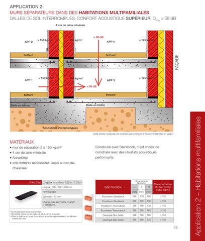
APPLICATION 2: MURS SÉPARATEURS DANS DES HABITATIONS MULTIFAMILIALES DALLES DE SOL INTERROMPUES, CONFORT ACOUSTIQUE SUPÉRIEUR, DnT,w > 58 dB
6 cm de laine minérale
4 cm de laine minérale
> 58 dB
> 58 dB > 125 kg/m2
APP 4
APP 2
flottant
flottant
Poids total de la dalle >500 kg/m2
APP 1
> 125 kg/m2
> 125 kg/m2
> 125 kg/m2
APP 3
> 150 kg/m2
> 150 kg/m2
flottant
APP 1
flottant
> 150 kg/m2
> 150 kg/m2
flottant
Meersgezinswoning - Toepassing 1 Application 1 – Habitations multifamiliales
flottant
flottant
flottant
Dalle en béton
Dalle en béton
Dalle en béton
Fondations ininterrompues
Fondations ininterrompues Cette solution proposée est soumise aux conditions annexes mentionnées en page 7.
Cette solution proposée est soumise aux conditions annexes mentionnées en page 7.
MATÉRIAUX
MATÉRIAUX
• mur de séparation 2 x 125 kg/m² • 6 cm de laine minérale • SonicStrip • sols flottants nécessaires, aussi au rez-dechaussée
• mur de séparation 2 x 150 kg/m² • 4 cm de laine minérale • SonicStrip • sols flottants nécessaires, aussi au rez-dechaussée Dimensions de fabrication
Type de brique SonicStrip Longueur du rouleau: 6,25 m / 12,5 m Largeur: 100 / 150 / 200 mm Forme Forme: plane
12
L
E
H
(mm) (mm) (mm) Porotherm Thermobrick
288
138
188
Masse surfacique du mur, mortier inclus (kg/m²)
Construire avec Silentbrick, c’est choisir de construire avec des résultats acoustiques performants.
Dimensions de fabrication
SonicStrip Longueur du rouleau: 6,25 m / 12,5 m
> 125
Largeur: 100 / 150 / 200 mm
Porotherm Thermobrick
288
138
138
> 125
Form Forme: plane
Epaiss Epaisseur: 10 mm
Porotherm Rendement Plus
300
138
234
> 125
Epaisseur: 10 mm Epa
Charg Charge max. par mètre courant: < 160 kN/m
Porotherm Rendement Plus
300
138
188
> 125
Desimpel Bloc treillis
288
138
188
> 125
Charge max. par mètre courant: Cha 160 kN/m < 16
Desimpel Bloc treillis
288
138
138
> 125
Desimpel Bloc treillis dent et rainure
300
138
238
> 125
Desimpel Bloc treillis dent et rainure
300
138
188
> 125
• SonicStrip placé sous tous les murs murs. • SonicStrip repose sur les dalles de sol du rez-de-chaussée. • Dans la dalle de sol: pose d’une double armature supplémentaire d’un diamètre minimal de 8 mm.
> 125 kg/m2
APP 3 > 58 dB
> 58 dB
Dalle en béton
> 125 kg/m2
APP 4
•S SonicStrip i S i placé l é sous tous lles murs. • SonicStrip repose sur les dalles de sol du rez-de-chaussée. • Dans la dalle de sol: pose d’une double armature supplémentaire d’un diamètre minimal de 8 mm.
Type de brique
L
E
H
(mm) (mm) (mm)
Masse surfacique du mur, mortier inclus (kg/m²)
Porotherm Silentbrick
288
138
188
> 150
Porotherm Silentbrick
288
138
138
> 150
Porotherm Thermobrick
288
188
138
> 150
Porotherm Thermobrick
288
188
188
> 150
Desimpel Bloc treillis
288
188
188
> 150
Desimpel Bloc treillis
288
188
138
> 150
13
Application 2 – Habitations multifamiliales
> 125 kg/m
FAÇADE
> 125 kg/m
2
FAÇADE
APP 2
2
WIENERBERGER RAPPORTS D’ESSAI ACOUSTIQUE Kij réductions de nœuds des Appartements application 2. Dans ce cas les coefficients de réduction pour l’émulsion de la double paroi + l’étage sur un socle de fondation avec une dalle de sol continue sont donnés. Pour la dalle de sol continue, un test spécifique n’a pas été fait. Mais par contre un test d’une dalle de béton a été pris dans les simulations d’appartements. (test 09) Il peut être considéré que ce test sera certainement l’approche la plus contraignante à cause d’un effet complémentaire de la dissipation qui émergera en cas des dalles de sol en pleine terre. Pour les étages, plus hauts des tests 05 & 06 ont été faits pour réductions des nœuds (sous charge) avec des strips acoustiques WB 160 (Sonic Strip) de Wienerberger. Pour arriver à la détermination DntW ceux-ci doivent être combinés avec les valeurs Rw des parois constructives. Un test cellulaire complémentaire a été fait de l’entière disposition avec les blocs treillis collés en combinaison avec les strips acoustiques (150kg/m² + Sonic Strips).
CSTC
BELGIAN BUILDING RESEARCH INSTITUTE INSTITUTION RECOGNIZED BY APPLICATION OF THE DECREE-LAW OF THE 30th OF JANUARY 1947
WTCB Tel : (32) 2 7164211
Offices : B-1932 Sint-Stevens-Woluwe, Lozenberg 7
Page 1/11
www.bbri.be
Measurement of the vibration reduction index Kij TEST CASE : Requested by : Wienerberger NV ipv Terca Beerse Test adress :
CASE 09 Contact company : Luc Vasseur
BBRI :
B. Ingelaere
Wienerberger NV Steenbakkersdam 10 in Beerse
General informations Test name : Applied standard: Date test : Date report : Responsable test : Collaboration : Excitation source : Excitation type :
K13, K12, K14, K15, K26 Pr EN 10848-1 and 4 26/09/2007 27/09/2007 Charlotte Crispin Debby Wuyts Hammer Stationary structure-borne
Junction informations Junction description : A cross junction composed of a continuous concrete floor and a double brick wall. A resilient joint is inserted between the brick walls and the floor.
Junction lenght [m] :
4.2
Wall informations
Designation ρ [kg/m³] Width [m] Length [m] Thickness d [m] Edyn [N/m²] μ
Junction diagram
Wall 1
Floor 2
Wall 3
Wall 4
Bricks 1108 4.2 3.1 0.14 5.60E+09 0.15
Concrete 2300 4.6 2.5 0.19 2.60E+10 0.2
Bricks 1108 4.4 2.3 0.14 5.60E+09 0.15
Bricks 1108 4.2 2.1 0.14 5.60E+09 0.15
Wall 5
Floor 6
X Precast Bricks Concrete concrete 1108 2300 2300 4.2 4.6 4.35 3.1 2.5 4.16 0.14 0.19 0.2 5.60E+09 2.60E+10 2.60E+10 0.15 0.2 0.2
BELGIAN BUILDING RESEARCH INSTITUTE INSTITUTION RECOGNIZED BY APPLICATION OF THE DECREE-LAW OF THE 30th OF JANUARY 1947
Page 2/11
Measurement apparatus and tests cells TEST CASE :
CASE 09
Test equipment Accelerometers : A real time analyser : Accelerometer calibrator : Excitation source : Computer + software :
Dytran (sensitivity : 1000mV/g) 01dB Orchestra (8 channels), 01dB Symphonie (2 channels) B&K Type 4294 Hammer dBFA32 v4.8, dBBATI32 v4.8
Test cells and mounting description Test adress : Wienerberger NV Steenbakkersdam 10 in Beerse Mounting description : A cross junction composed of a continuous concrete floor and a double brick wall. A resilient joint is inserted between the brick walls and the floor. The resilient joint is a resinbonded rubber with a thickness of 0.01 m and a width of 0.14 m. The brick walls are not plastered. The cavity between the brick walls is filled with mineral wool and measures Âą 0.03 m.
BELGIAN BUILDING RESEARCH INSTITUTE INSTITUTION RECOGNIZED BY APPLICATION OF THE DECREE-LAW OF THE 30th OF JANUARY 1947
Page 3/11
The structural reverberation time
Ts
TEST CASE :
CASE 09
Wall 1
Floor 2
Wall 3
Wall 4
Wall 5
Floor 6
X
X
100
0.82
0.85
0.78
0.78
0.82
0.85
0.79
0.91
125 160 200 250 315
0.48 0.4 0.4 0.47 0.36 0.37 0.3 0.29 0.25 0.2 0.19 0.15 0.12 0.09 0.08 0.07 0.05
0.87 0.56 0.8 0.47 0.71 0.44 0.35 0.3 0.23 0.19 0.15 0.13 0.1 0.09 0.09 0.07 0.06
0.72 0.72 0.72 0.72 0.73 0.6 0.44 0.53 0.44 0.35 0.28 0.19 0.13 0.15 0.13 0.11 0.07
0.72 0.72 0.72 0.72 0.73 0.6 0.44 0.53 0.44 0.35 0.28 0.19 0.13 0.15 0.13 0.11 0.07
0.48 0.4 0.4 0.47 0.36 0.37 0.3 0.29 0.25 0.2 0.19 0.15 0.12 0.09 0.08 0.07 0.05
0.87 0.56 0.8 0.47 0.71 0.44 0.35 0.3 0.23 0.19 0.15 0.13 0.1 0.09 0.09 0.07 0.06
0.63 0.57 0.56 0.34 0.29 0.23 0.24 0.18 0.13 0.11 0.09 0.13 0.08 0.07 0.09 0.07 0.06
0.72 0.46 0.5 0.61 0.32 0.39 0.45 0.36 0.29 0.23 0.23 0.19 0.18 0.17 0.14 0.12 0.1
400 500 630 800 1000 1250
1600 2000 2500 3150 4000 5000
ηtot
The total loss factor
Wall 1 Floor 2 Wall 3 Wall 4 Wall 5 Floor 6 X 100 125 160 200 250 315
400 500 630 800 1000 1250
1600 2000 2500 3150 4000 5000
0.027 0.037 0.034 0.028 0.019 0.019 0.015 0.015 0.012 0.011 0.011 0.009 0.009 0.009 0.010 0.009 0.008 0.009
0.026 0.020 0.025 0.014 0.019 0.010 0.013 0.013 0.012 0.012 0.012 0.012 0.011 0.011 0.010 0.008 0.008 0.007
0.028 0.024 0.019 0.015 0.012 0.010 0.009 0.010 0.007 0.006 0.006 0.006 0.007 0.008 0.006 0.005 0.005 0.006
0.028 0.024 0.019 0.015 0.012 0.010 0.009 0.010 0.007 0.006 0.006 0.006 0.007 0.008 0.006 0.005 0.005 0.006
0.027 0.037 0.034 0.028 0.019 0.019 0.015 0.015 0.012 0.011 0.011 0.009 0.009 0.009 0.010 0.009 0.008 0.009
0.026 0.020 0.025 0.014 0.019 0.010 0.013 0.013 0.012 0.012 0.012 0.012 0.011 0.011 0.010 0.008 0.008 0.007
0.028 0.028 0.024 0.020 0.026 0.024 0.024 0.018 0.019 0.021 0.020 0.020 0.011 0.014 0.013 0.008 0.008 0.007
X 0.024 0.024 0.030 0.022 0.014 0.022 0.014 0.010 0.010 0.009 0.010 0.008 0.007 0.006 0.005 0.005 0.005 0.004
BELGIAN BUILDING RESEARCH INSTITUTE INSTITUTION RECOGNIZED BY APPLICATION OF THE DECREE-LAW OF THE 30th OF JANUARY 1947
Page 4/11
Kij for the transmission path 1- 3 : Result
Kij
CASE 09
TEST CASE :
Direction averaged velocity level difference : Dvij,bid
Test name : Test date :
K13
Direction averaged velocity level difference
26/09/2007
70
60
Dvij [dB]
50
20
155.1
155.1
B [Nm]:
1.28E+06
1.28E+06
fci [Hz] :
202.5
202.5
n [1/Hz]:
0.07
0.06
Dv13
10
Dv31 Dv13 bid
2500
3150
4000
5000
2500
3150
4000
5000
2000
1600
1250
1000
800
630
500
400
315
250
200
100
0 160
10.1
125
Wall 3
13.2
Frequency [Hz]
The vibration reduction index : Kij The vibration reduction index, Kij
40
30
20
10
Frequency [Hz]
2000
1600
1250
1000
800
630
500
400
315
0 250
49.3
50
200
Single value [dB] :
60
160
K13 37.1 34.6 43.3 43.0 40.4 46.1 43.8 51.5 50.9 54.7 56.3 57.4 56.4 58.4 58.5 56.7 59.9 56.3
125
Frequency [Hz] 100 125 160 200 250 315 400 500 630 800 1000 1250 1600 2000 2500 3150 4000 5000
70
100
ρ' [kg/m²] :
Wall 1
30
Kij [dB]
S [m²] :
40
BELGIAN BUILDING RESEARCH INSTITUTE INSTITUTION RECOGNIZED BY APPLICATION OF THE DECREE-LAW OF THE 30th OF JANUARY 1947
Page 5/11
Kij for the transmission path 1- 2 : Result
Kij
CASE 09
TEST CASE :
Direction averaged velocity level difference : Dvij,bid
Test name : Test date :
K12
Direction averaged velocity level difference
26/09/2007
50 45 40 35
Dvij [dB]
30 25 20 15
155.1
437.0
B [Nm]:
1.28E+06
1.49E+07
fci [Hz] :
202.5
99.8
n [1/Hz]:
0.07
0.03
10
Dv12 Dv21
5
Dv12 bid
2500
3150
4000
5000
2500
3150
4000
5000
2000
1600
1250
1000
800
630
500
400
315
250
200
100
0 160
11.3
125
Floor 2
13.2
Frequency [Hz]
The vibration reduction index : Kij The vibration reduction index, Kij
25
20
15
10
5
Frequency [Hz]
2000
1600
1250
1000
800
630
500
400
315
0 250
30.5
30
200
Single value [dB] :
35
160
K12 27.6 25.6 29.8 30.6 25.1 27.8 27.7 31.1 31.6 32.5 34.1 34.0 34.3 34.8 35.5 33.6 34.9 35.5
125
Frequency [Hz] 100 125 160 200 250 315 400 500 630 800 1000 1250 1600 2000 2500 3150 4000 5000
40
100
ρ' [kg/m²] :
Wall 1
Kij [dB]
S [m²] :
BELGIAN BUILDING RESEARCH INSTITUTE INSTITUTION RECOGNIZED BY APPLICATION OF THE DECREE-LAW OF THE 30th OF JANUARY 1947
Page 6/11
Kij for the transmission path 1- 4 : Result
Kij
CASE 09
TEST CASE :
Direction averaged velocity level difference : Dvij,bid
Test name : Test date :
K14
Direction averaged velocity level difference
26/09/2007
80
70
60
Dvij [dB]
50
40
30
Wall 1
Wall 4
S [m²] :
13.2
9.0
ρ' [kg/m²] :
155.1
155.1
B [Nm]:
1.28E+06
1.28E+06
fci [Hz] :
202.5
202.5
n [1/Hz]:
0.07
0.05
20 Dv14
10
Dv41 Dv14 bid
2500
3150
4000
5000
2500
3150
4000
5000
2000
1600
1250
1000
800
630
500
400
315
250
200
160
125
100
0 Frequency [Hz]
The vibration reduction index : Kij The vibration reduction index, Kij
50
40
30
20
10
Frequency [Hz]
2000
1600
1250
1000
800
630
500
400
315
250
200
0 160
49.4
60
125
Single value [dB] :
70
100
K14 40.2 34.9 42.5 38.5 45.8 39.4 44.1 52.0 55.6 52.0 56.0 61.5 62.7 66.7 63.9 63.3 63.0 61.2
Kij [dB]
Frequency [Hz] 100 125 160 200 250 315 400 500 630 800 1000 1250 1600 2000 2500 3150 4000 5000
80
BELGIAN BUILDING RESEARCH INSTITUTE INSTITUTION RECOGNIZED BY APPLICATION OF THE DECREE-LAW OF THE 30th OF JANUARY 1947
Page 7/11
Kij for the transmission path 1- 5 : Result
Kij
CASE 09
TEST CASE :
Direction averaged velocity level difference : Dvij,bid
Test name : Test date :
K15
Direction averaged velocity level difference
26/09/2007
60
50
Dvij [dB]
40
155.1
155.1
B [Nm]:
1.28E+06
1.28E+06
fci [Hz] :
202.5
202.5
n [1/Hz]:
0.07
0.07
Dv15
10
Dv51 Dv15 bid
2500
3150
4000
5000
2500
3150
4000
5000
2000
1600
1250
1000
800
630
500
400
315
250
200
100
0 160
13.2
125
13.2
20
Frequency [Hz]
The vibration reduction index : Kij The vibration reduction index, Kij
30
20
10
Frequency [Hz]
2000
1600
1250
1000
800
630
500
400
315
0 250
31.9
40
200
Single value [dB] :
50
160
K15 15.7 15.9 17.1 21.4 24.2 25.8 29.4 32.2 37.8 38.5 37.4 40.2 43.5 46.6 48.2 48.8 49.3 49.3
125
Frequency [Hz] 100 125 160 200 250 315 400 500 630 800 1000 1250 1600 2000 2500 3150 4000 5000
60
100
ρ' [kg/m²] :
Wall 5
Kij [dB]
S [m²] :
Wall 1
30
BELGIAN BUILDING RESEARCH INSTITUTE INSTITUTION RECOGNIZED BY APPLICATION OF THE DECREE-LAW OF THE 30th OF JANUARY 1947
Page 8/11
Kij for the transmission path 2- 6 : Result
Kij
CASE 09
TEST CASE :
Direction averaged velocity level difference : Dvij,bid
Test name : Test date :
K26
Direction averaged velocity level difference
26/09/2007
8 7 6 5
Dvij [dB]
4 3 2 1
437.0
437.0
B [Nm]:
1.49E+07
1.49E+07
fci [Hz] :
99.8
99.8
n [1/Hz]:
0.03
0.03
0
Dv26 Dv62
-1
Dv26 bid
2500
3150
4000
5000
2500
3150
4000
5000
2000
1600
1250
800
1000
630
500
400
315
250
200
100
-2 160
11.3
125
Floor 6
11.3
Frequency [Hz]
The vibration reduction index : Kij The vibration reduction index, Kij
4
3
2
1
Frequency [Hz]
2000
1600
1250
1000
800
630
500
400
315
0 250
2.5
5
200
Single value [dB] :
6
160
K26 3.6 3.7 3.1 4.6 2.6 6.3 1.0 0.9 2.9 1.7 1.8 1.0 0.5 0.8 0.9 1.0 2.6 4.4
125
Frequency [Hz] 100 125 160 200 250 315 400 500 630 800 1000 1250 1600 2000 2500 3150 4000 5000
7
100
ρ' [kg/m²] :
Floor 2
Kij [dB]
S [m²] :
BELGIAN BUILDING RESEARCH INSTITUTE INSTITUTION RECOGNIZED BY APPLICATION OF THE DECREE-LAW OF THE 30th OF JANUARY 1947
Page 9/11
Annex 1 : MEASUREMENT METHODS Measurement method to determine the vibration reduction index, Kij General The vibration reduction index Kij expresses, in a way, the attenuation of the power flow through a junction. The draft prEN ISO 10848-1 to 4 gives a measurement method to obtain this index in laboratory. The principle of measurement for Kij is based on tis formula :
The required quantities are the length of the junction lij [m], the direction averaged level difference [dB] and the equivalent absorption lengths ai [m] and aj [m]. All these quantities are obtained by vibration measurements with structure-borne excitation. is obtained from the mean value of the velocity level differences Dv,ij and Dv,ij. Dv,ij (Dv,ji) is the difference between the surface average velocity level of the wall i (j) and the wall j (i) when the wall i (j) is excited at several points. ai and ai are determined according to the measurement of the structural reverberation times Ts,i and Ts,j :
Sj is the surface area of the wall j [m²]; Tsj is the structural reverberation time of the wall i [s]; c0 is the speed of sound in air [m/s]; f is the current frequency [Hz]; fref is the reference frequency [fref = 1000 Hz]. Generation of vibration on the source element Multiple hammer hits with approximately the same strength are given over an area of 1 m2 –2 m2 during a time period of 30 s. Performance of the measurement On each element (source and receiving plate) three (3) excitation positions and a twelve (12) transducer positions are be used. For each excitation position four (4) different pairs of transducer positions is used on each element. All positions are randomly distributed over the surface of the element, bu not symmetrical. The transducer positions and excitation points shall be arranged using the following minimum distances: · 0,5 m between excitation points and the test element boundaries; · 1,0 m between excitation points and the junction under test; · 1,0 m between excitation points and the associated transducer positions; · 0,25 m between transducer positions and the test element boundaries; · 0,5 m between the individual transducer positions. The maximum distance between transducer positions and the junction under test is 3,5 m. In each frequency band the measured velocity level shall be at least 10 dB higher than the background noise level. in any frequency band. If this is not fulfilled, corrections shall be applied as shown in EN ISO 140-3. The correction value must not exceed 1,3 dB.
Measurement method to determine the structural reverberation time, Ts Ts is the structural reverberation time of a wall [s]. It represents the time that would be required for the velocity or acceleration level in a structure to decrease by 60 dB after the structure-borne sound source has stopped.
The hammer excitation method is used. Different masses and materials are used for an impact hammer because different material leads to different excitations in frequency bands. Measurement and excitation points At least three excitation points shall be used on the test element. At least three transducer positions shall be used for each excitation point. The transducer positions and the excitation points shall be arranged using the following minimum distances: · 0,5 m between transducer positions and the test element boundaries; · 1 m between the excitation point and the associated transducer positions; · 0,5 m between the individual transducer positions. The measurement points shall be randomly distributed over the test element.
BELGIAN BUILDING RESEARCH INSTITUTE INSTITUTION RECOGNIZED BY APPLICATION OF THE DECREE-LAW OF THE 30th OF JANUARY 1947
Page 10/11
Annex 2 : Checking the measurement conditions TEST CASE :
CASE 09
1. Weak coupling : the measured Kij may not be relevant due to strong coupling f(Hz)
Path 1-3
Path 1-2
Path 1-4
Path 1-5
Path 2-6
100 125 160 200 250 315 400 500 630 800 1000 1250 1600 2000 2500 3150 4000 5000
OK OK OK OK OK OK OK OK OK OK OK OK OK OK OK OK OK OK
OK OK OK OK OK OK OK OK OK OK OK OK OK OK OK OK OK OK
OK OK OK OK OK OK OK OK OK OK OK OK OK OK OK OK OK OK
OK OK OK OK OK OK OK OK OK OK OK OK OK OK OK OK OK OK
OK OK OK OK OK OK OK OK OK OK OK OK OK OK OK OK OK OK
2. Diffuse vibration fields : if the measured velocity level decreases by more than 6 dB over the allowed measurement area for any elemen of the tested junction, when the accelerometer is moved away from a stationary vibration source, then the measured Kij may not be relevant. f(Hz) 100 125 160 200 250 315 400 500 630 800 1000 1250 1600 2000 2500 3150 4000 5000
K13 Wall 1 Wall 3 NOK NOK NOK NOK NOK NOK NOK OK NOK NOK NOK NOK NOK OK NOK NOK OK NOK OK NOK OK OK OK OK OK OK OK OK OK OK OK OK OK OK OK OK
K12 Wall 1 Floor 2 NOK NOK NOK NOK NOK NOK NOK OK NOK NOK NOK NOK NOK NOK NOK NOK OK NOK OK OK NOK NOK OK NOK NOK OK OK NOK OK OK OK OK NOK OK OK OK
K14 Wall 1 Wall 4 NOK NOK NOK NOK NOK NOK NOK NOK NOK NOK OK NOK NOK NOK NOK NOK OK NOK OK OK NOK OK NOK OK OK OK OK OK OK OK OK OK OK OK NOK OK
K15 Wall 1 Wall 5 NOK OK OK OK NOK OK NOK OK NOK OK NOK OK OK OK NOK OK OK OK OK OK OK OK OK OK OK OK OK OK OK OK OK OK OK OK OK OK
K26 Floor 2 OK OK OK OK OK OK OK OK OK OK OK OK OK OK OK OK OK OK
Floor 6 OK OK OK OK OK OK OK OK OK OK OK OK OK OK OK OK OK OK
3. Background noise : in each frequency band the measured velocity level shall be at least 10 dB higher than the background noise level.
f(Hz) 100 125 160 200 250 315 400 500 630 800 1000 1250 1600 2000 2500 3150 4000 5000
K13 Wall 1 Wall 1 NOK OK OK OK OK OK OK OK OK OK OK OK OK OK OK OK OK OK OK OK OK OK OK OK OK OK OK OK OK NOK OK NOK NOK NOK NOK NOK
K12 Wall 1 Floor 2 OK OK OK OK OK OK OK OK OK OK OK OK OK OK OK OK OK OK OK OK OK OK OK OK OK OK OK OK OK OK OK OK OK OK OK OK
K14 Wall 1 Wall 4 NOK OK OK OK NOK NOK OK OK NOK OK OK OK OK OK OK OK OK OK OK OK OK NOK NOK NOK NOK NOK NOK NOK NOK NOK NOK NOK NOK NOK NOK NOK
K15 Wall 1 Wall 5 OK NOK OK NOK NOK NOK OK NOK OK NOK OK NOK OK NOK OK NOK OK NOK OK NOK NOK NOK NOK NOK NOK NOK NOK NOK NOK NOK NOK NOK NOK NOK NOK NOK
K26 Floor 2 NOK NOK NOK NOK NOK NOK NOK NOK NOK NOK NOK NOK NOK NOK NOK NOK NOK NOK
Floor 6 NOK NOK NOK NOK NOK NOK NOK NOK NOK NOK NOK NOK NOK NOK NOK NOK NOK NOK
BELGIAN BUILDING RESEARCH INSTITUTE INSTITUTION RECOGNIZED BY APPLICATION OF THE DECREE-LAW OF THE 30th OF JANUARY 1947
Page 11/11
Annex 2 : Checking the measurement conditions CASE 09
TEST CASE :
4. Number of modes in the 1/3 octave band, N : the mode count in 1/3 octave should be higher than 5 modes f(Hz) 100 125 160 200 250 315 400 500 630 800 1000 1250 1600 2000 2500 3150 4000 5000
Wall 1 1.7 2.1 2.7 3.3 4.2 5.3 6.7 8.3 10.5 13.4 16.7 20.9 26.7 33.4 41.7 52.6 66.8 83.5
Floor 2 0.7 0.9 1.1 1.4 1.8 2.2 2.8 3.5 4.4 5.6 7.1 8.8 11.3 14.1 17.6 22.2 28.2 35.3
Wall 3 1.3 1.6 2.1 2.6 3.2 4.0 5.1 6.4 8.1 10.3 12.8 16.0 20.5 25.7 32.1 40.4 51.3 64.2
Wall 4 1.1 1.4 1.8 2.3 2.8 3.6 4.6 5.7 7.2 9.1 11.4 14.2 18.2 22.8 28.4 35.8 45.5 56.9
Wall 5 1.7 2.1 2.7 3.3 4.2 5.3 6.7 8.3 10.5 13.4 16.7 20.9 26.7 33.4 41.7 52.6 66.8 83.5
Floor 6 0.7 0.9 1.1 1.4 1.8 2.2 2.8 3.5 4.4 5.6 7.1 8.8 11.3 14.1 17.6 22.2 28.2 35.3
5. Modal overlap factor, M : for heavy element, it must be checked whether the modal overlap factor is at least unity at 250 Hz and higher f(Hz) 100 125 160 200 250 315 400 500 630 800 1000 1250 1600 2000 2500 3150 4000 5000
Wall 1 0.19 0.33 0.40 0.40 0.34 0.44 0.43 0.53 0.55 0.64 0.80 0.84 1.06 1.33 1.77 2.00 2.28 3.19
Floor 2 0.08 0.08 0.12 0.08 0.14 0.10 0.15 0.19 0.22 0.29 0.36 0.45 0.52 0.67 0.75 0.75 0.96 1.12
Wall 3 0.16 0.17 0.17 0.17 0.17 0.17 0.20 0.28 0.23 0.28 0.35 0.44 0.65 0.94 0.82 0.94 1.12 1.75
Wall 4 0.14 0.15 0.15 0.15 0.15 0.15 0.18 0.25 0.21 0.25 0.31 0.39 0.57 0.84 0.73 0.84 0.99 1.55
Wall 5 0.19 0.33 0.40 0.40 0.34 0.44 0.43 0.53 0.55 0.64 0.80 0.84 1.06 1.33 1.77 2.00 2.28 3.19
Floor 6 0.08 0.08 0.12 0.08 0.14 0.10 0.15 0.19 0.22 0.29 0.36 0.45 0.52 0.67 0.75 0.75 0.96 1.12
TEST 09 : 26/09/2007 f
K13_09
K12_09
K14_09
K15_09
K26_09
[Hz] 50 63 80 100 125 160 200 250 315 400 500 630 800 1000 1250 1600 2000 2500 3150 4000 5000
[dB]
[dB]
[dB]
[dB]
[dB]
37,07301 27,59504 40,23715 15,66228 3,63145 34,63781 25,57177 34,85277 15,85486 3,688323 43,33232 29,79628 42,48431 17,05049 3,141527 42,99943 30,59027 38,54479 21,36238 4,574679 40,37715 25,11671 45,82327 24,15823 2,577123 46,05698 27,76468 39,36828 25,77364 6,26612 43,81147 27,7277 44,07769 29,44517 0,964651 51,4876 31,10385 51,99778 32,183 0,880538 50,85915 31,55191 55,62978 37,75474 2,928505 54,68621 32,53344 51,98667 38,48636 1,745038 56,27582 34,11644 55,9818 37,4406 1,785687 57,41255 33,97576 61,47023 40,19474 1,012255 56,35073 34,25283 62,70044 43,45698 0,509778 58,35451 34,7603 66,72415 46,56027 0,849353 58,53526 35,49304 63,85168 48,20786 0,915132 56,6816 33,55357 63,30938 48,84429 1,023038 59,90688 34,88012 63,03273 49,29765 2,602179 56,29162 35,48977 61,16124 49,26447 4,414387
Single valu49,3296 30,4979 49,4311 31,8665 2,52607
CSTC
BELGIAN BUILDING RESEARCH INSTITUTE INSTITUTION RECOGNIZED BY APPLICATION OF THE DECREE-LAW OF THE 30th OF JANUARY 1947
WTCB Tel : (32) 2 7164211
Offices : B-1932 Sint-Stevens-Woluwe, Lozenberg 7
Page 1/9
www.bbri.be
Measurement of the vibration reduction index Kij TEST CASE : Requested by : Wienerberger NV Test adress :
CASE 05
Contact company : Luc Vasseur
BBRI :
B. Ingelaere
Wienerberger NV Steenbakkersdam 10 in Beerse
General informations Test name : Applied standard: Date test : Date report : Responsable test : Collaboration : Excitation source : Excitation type :
K12, K13, K23 Pr EN 10848-1 and 4 02/02/2007 05/02/2007 Charlotte Crispin Lieven De Geetere Hammer Stationary structure-borne
Junction informations Junction description : A T-junction with flexible interlayer: the vertical walls are made of bricks (type : Silentbrick, thickness : 0.14m) and interrupted by horizontal hollowcore slabs (floor 2). The resilient joint is placed between the slabs and wall 1. Junction lenght [m] :
4.17
Wall informations Wall 1 Designation ρ [kg/m³] Width [m] Length [m] Thickness d [m] Edyn [N/m²] μ
Junction diagram
Bricks 1108 4.2 2.8 0.14 5.60E+09 0.15
Floor 2 Hollow slabs 1575 4.4 4.2 0.20 2.60E+10 0.2
Wall 3
X
Bricks 1108 4.4 2.6 0.14 5.60E+09 0.15
Sol béton 1000 3.0 2.1 0.14 1.10E+10 0.01
X
X
X Precast Bricks Bricks concrete 1108 1108 2300 4.4 4.2 4.35 2.6 2.8 4.16 0.14 0.14 0.2 5.60E+09 5.60E+09 2.60E+10 0.15 0.15 0.2
BELGIAN BUILDING RESEARCH INSTITUTE INSTITUTION RECOGNIZED BY APPLICATION OF THE DECREE-LAW OF THE 30th OF JANUARY 1947
Page 2/9
Measurement apparatus and tests cells TEST CASE :
CASE 05
Test equipment Accelerometers : A real time analyser : Accelerometer calibrator : Excitation source : Computer + software :
Dytran (sensitivity : 1000mV/g) 01dB Orchestra (8 channels), 01dB Symphonie (2 channels) B&K Type 4294 Hammer dBFA32 v4.8, dBBATI32 v4.8
Test cells and mounting description Test adress : Wienerberger NV Steenbakkersdam 10 in Beerse Mounting description : A T-junction with flexible interlayer: the vertical walls are made of bricks (type : Silentbrick, thickness : 0.14m) and interrupted by 4 horizontal hollowcore slabs. The resilient joint is placed between the slabs and wall 1. The resilient joint is a resinbonded rubber with a thickness of 0.01 m and a width of 0.14 m. Wall n째1 is plastered on the CEL1 side.
BELGIAN BUILDING RESEARCH INSTITUTE INSTITUTION RECOGNIZED BY APPLICATION OF THE DECREE-LAW OF THE 30th OF JANUARY 1947
Page 3/9
The structural reverberation time
Ts
TEST CASE :
CASE 05
Wall 1
Floor 2
Wall 3
X
X
X
X
X
100
0.88
0.91
1.42
0.91
0.76
0.5
0.79
0.91
125 160 200 250 315
0.57 0.47 0.36 0.49 0.32 0.29 0.26 0.23 0.18 0.18 0.15 0.13 0.11 0.08 0.07 0.06 0.06
0.66 0.44 0.45 0.26 0.23 0.22 0.14 0.14 0.15 0.11 0.1 0.11 0.07 0.06 0.09 0.06 0.05
1.24 1.37 0.71 0.55 0.41 0.41 0.29 0.2 0.17 0.14 0.11 0.1 0.09 0.09 0.07 0.05 0.05
0.72 0.46 0.5 0.61 0.32 0.39 0.45 0.36 0.29 0.23 0.23 0.19 0.18 0.17 0.14 0.12 0.1
1.23 1.6 0.84 0.79 0.82 0.68 0.77 0.82 0.73 0.49 0.46 0.36 0.23 0.15 0.13 0.1 0.09
0.54 0.41 0.31 0.43 0.31 0.26 0.26 0.23 0.2 0.18 0.16 0.14 0.1 0.08 0.08 0.07 0.06
0.63 0.57 0.56 0.34 0.29 0.23 0.24 0.18 0.13 0.11 0.09 0.13 0.08 0.07 0.09 0.07 0.06
0.72 0.46 0.5 0.61 0.32 0.39 0.45 0.36 0.29 0.23 0.23 0.19 0.18 0.17 0.14 0.12 0.1
400 500 630 800 1000 1250
1600 2000 2500 3150 4000 5000
ηtot
The total loss factor
Wall 1 Floor 2 Wall 3 X 100 125 160 200 250 315
400 500 630 800 1000 1250
1600 2000 2500 3150 4000 5000
0.025 0.031 0.029 0.031 0.018 0.022 0.019 0.017 0.015 0.015 0.012 0.012 0.011 0.010 0.011 0.010 0.009 0.007
0.024 0.027 0.031 0.024 0.034 0.030 0.025 0.031 0.025 0.018 0.020 0.018 0.013 0.016 0.015 0.008 0.009 0.009
0.015 0.014 0.010 0.015 0.016 0.017 0.013 0.015 0.017 0.016 0.016 0.016 0.014 0.012 0.010 0.010 0.011 0.009
0.024 0.024 0.030 0.022 0.014 0.022 0.014 0.010 0.010 0.009 0.010 0.008 0.007 0.006 0.005 0.005 0.005 0.004
X 0.029 0.014 0.009 0.013 0.011 0.009 0.008 0.006 0.004 0.004 0.004 0.004 0.004 0.005 0.006 0.005 0.006 0.005
X 0.044 0.033 0.034 0.035 0.020 0.023 0.021 0.017 0.015 0.014 0.012 0.011 0.010 0.011 0.011 0.009 0.008 0.007
X 0.028 0.028 0.024 0.020 0.026 0.024 0.024 0.018 0.019 0.021 0.020 0.020 0.011 0.014 0.013 0.008 0.008 0.007
X 0.024 0.024 0.030 0.022 0.014 0.022 0.014 0.010 0.010 0.009 0.010 0.008 0.007 0.006 0.005 0.005 0.005 0.004
BELGIAN BUILDING RESEARCH INSTITUTE INSTITUTION RECOGNIZED BY APPLICATION OF THE DECREE-LAW OF THE 30th OF JANUARY 1947
Page 4/9
Kij for the transmission path 1- 2 : Result
Kij
CASE 05
TEST CASE :
Direction averaged velocity level difference : Dvij,bid
Test name : Test date :
K12
Direction averaged velocity level difference
02/02/2007
60
50
Dvij [dB]
40
155.1
315.0
B [Nm]:
1.28E+06
1.73E+07
fci [Hz] :
202.5
78.4
n [1/Hz]:
0.07
0.04
10
Dv12 Dv21 Dv12 bid
2500
3150
4000
5000
2500
3150
4000
5000
2000
1600
1250
1000
800
630
500
400
315
250
200
100
0 160
18.1
125
11.8
20
Frequency [Hz]
The vibration reduction index : Kij The vibration reduction index, Kij
30 25 20 15 10 5
Frequency [Hz]
2000
1600
1250
1000
800
630
500
400
315
0 250
24.2
35
200
Single value [dB] :
40
160
K12 21.3 18.3 21.9 19.7 20.7 19.9 21.1 22.6 25.2 27.4 29.0 32.3 34.2 35.8 37.1 37.9 38.3 39.8
125
Frequency [Hz] 100 125 160 200 250 315 400 500 630 800 1000 1250 1600 2000 2500 3150 4000 5000
45
100
ρ' [kg/m²] :
Floor 2
Kij [dB]
S [m²] :
Wall 1
30
BELGIAN BUILDING RESEARCH INSTITUTE INSTITUTION RECOGNIZED BY APPLICATION OF THE DECREE-LAW OF THE 30th OF JANUARY 1947
Page 5/9
Kij for the transmission path 1- 3 : Result
Kij
CASE 05
TEST CASE :
Direction averaged velocity level difference : Dvij,bid
Test name : Test date :
K13
Direction averaged velocity level difference
02/02/2007
60
50
Dvij [dB]
40
155.1
155.1
B [Nm]:
1.28E+06
1.28E+06
fci [Hz] :
202.5
202.5
n [1/Hz]:
0.07
0.06
10
Dv13 Dv31 Dv13 bid
2500
3150
4000
5000
2500
3150
4000
5000
2000
1600
1250
1000
800
630
500
400
315
250
200
100
0 160
11.2
125
11.8
20
Frequency [Hz]
The vibration reduction index : Kij The vibration reduction index, Kij
35 30 25 20 15 10 5
Frequency [Hz]
2000
1600
1250
1000
800
630
500
400
315
0 250
30.3
40
200
Single value [dB] :
45
160
K13 23.9 29.4 26.2 27.4 32.3 28.8 27.2 28.0 30.6 31.4 32.4 35.0 37.2 37.9 38.4 39.4 42.4 45.4
125
Frequency [Hz] 100 125 160 200 250 315 400 500 630 800 1000 1250 1600 2000 2500 3150 4000 5000
50
100
ρ' [kg/m²] :
Wall 3
Kij [dB]
S [m²] :
Wall 1
30
BELGIAN BUILDING RESEARCH INSTITUTE INSTITUTION RECOGNIZED BY APPLICATION OF THE DECREE-LAW OF THE 30th OF JANUARY 1947
Page 6/9
Kij for the transmission path 2- 3 : Result
Kij
CASE 05
TEST CASE :
Direction averaged velocity level difference : Dvij,bid
Test name : Test date :
K23
Direction averaged velocity level difference
02/02/2007
30
25
Dvij [dB]
20
315.0
155.1
B [Nm]:
1.73E+07
1.28E+06
fci [Hz] :
78.4
202.5
n [1/Hz]:
0.04
0.06
5
Dv23 Dv32 Dv23 bid
2500
3150
4000
5000
2500
3150
4000
5000
2000
1600
1250
1000
800
630
500
400
315
250
200
100
0 160
11.2
125
18.1
10
Frequency [Hz]
The vibration reduction index : Kij The vibration reduction index, Kij
14 12 10 8 6 4 2
Frequency [Hz]
2000
1600
1250
1000
800
630
500
400
315
0 250
11.5
16
200
Single value [dB] :
18
160
K23 16.4 17.7 15.9 16.5 15.5 12.2 12.6 12.1 8.3 8.8 9.2 8.1 9.9 8.0 8.5 9.6 13.9 11.3
125
Frequency [Hz] 100 125 160 200 250 315 400 500 630 800 1000 1250 1600 2000 2500 3150 4000 5000
20
100
ρ' [kg/m²] :
Wall 3
Kij [dB]
S [m²] :
Floor 2
15
BELGIAN BUILDING RESEARCH INSTITUTE INSTITUTION RECOGNIZED BY APPLICATION OF THE DECREE-LAW OF THE 30th OF JANUARY 1947
Page 7/9
Annex 1 : MEASUREMENT METHODS Measurement method to determine the vibration reduction index, Kij General The vibration reduction index Kij expresses, in a way, the attenuation of the power flow through a junction. The draft prEN ISO 10848-1 to 4 gives a measurement method to obtain this index in laboratory. The principle of measurement for Kij is based on tis formula :
The required quantities are the length of the junction lij [m], the direction averaged level difference [dB] and the equivalent absorption lengths ai [m] and aj [m]. All these quantities are obtained by vibration measurements with structure-borne excitation. is obtained from the mean value of the velocity level differences Dv,ij and Dv,ij. Dv,ij (Dv,ji) is the difference between the surface average velocity level of the wall i (j) and the wall j (i) when the wall i (j) is excited at several points. ai and ai are determined according to the measurement of the structural reverberation times Ts,i and Ts,j :
Sj is the surface area of the wall j [m²]; Tsj is the structural reverberation time of the wall i [s]; c0 is the speed of sound in air [m/s]; f is the current frequency [Hz]; fref is the reference frequency [fref = 1000 Hz]. Generation of vibration on the source element Multiple hammer hits with approximately the same strength are given over an area of 1 m2 –2 m2 during a time period of 30 s. Performance of the measurement On each element (source and receiving plate) three (3) excitation positions and a twelve (12) transducer positions are be used. For each excitation position four (4) different pairs of transducer positions is used on each element. All positions are randomly distributed over the surface of the element, bu not symmetrical. The transducer positions and excitation points shall be arranged using the following minimum distances: · 0,5 m between excitation points and the test element boundaries; · 1,0 m between excitation points and the junction under test; · 1,0 m between excitation points and the associated transducer positions; · 0,25 m between transducer positions and the test element boundaries; · 0,5 m between the individual transducer positions. The maximum distance between transducer positions and the junction under test is 3,5 m. In each frequency band the measured velocity level shall be at least 10 dB higher than the background noise level. in any frequency band. If this is not fulfilled, corrections shall be applied as shown in EN ISO 140-3. The correction value must not exceed 1,3 dB.
Measurement method to determine the structural reverberation time, Ts Ts is the structural reverberation time of a wall [s]. It represents the time that would be required for the velocity or acceleration level in a structure to decrease by 60 dB after the structure-borne sound source has stopped.
The hammer excitation method is used. Different masses and materials are used for an impact hammer because different material leads to different excitations in frequency bands. Measurement and excitation points At least three excitation points shall be used on the test element. At least three transducer positions shall be used for each excitation point. The transducer positions and the excitation points shall be arranged using the following minimum distances: · 0,5 m between transducer positions and the test element boundaries; · 1 m between the excitation point and the associated transducer positions; · 0,5 m between the individual transducer positions. The measurement points shall be randomly distributed over the test element.
BELGIAN BUILDING RESEARCH INSTITUTE INSTITUTION RECOGNIZED BY APPLICATION OF THE DECREE-LAW OF THE 30th OF JANUARY 1947
Page 8/9
Annex 2 : Checking the measurement conditions TEST CASE :
CASE 05
1. Weak coupling : the measured Kij may not be relevant due to strong coupling f(Hz)
Path 1-2
Path 1-3
Path 2-3
100 125 160 200 250 315 400 500 630 800 1000 1250 1600 2000 2500 3150 4000 5000
OK OK OK OK OK OK OK OK OK OK OK OK OK OK OK OK OK OK
OK OK OK OK OK OK OK OK OK OK OK OK OK OK OK OK OK OK
OK OK OK OK OK OK OK OK OK OK OK OK OK OK OK OK OK OK
2. Diffuse vibration fields : if the measured velocity level decreases by more than 6 dB over the allowed measurement area for any elemen of the tested junction, when the accelerometer is moved away from a stationary vibration source, then the measured Kij may not be relevant. f(Hz) 100 125 160 200 250 315 400 500 630 800 1000 1250 1600 2000 2500 3150 4000 5000
K12 Wall 1 Floor 2 NOK NOK OK NOK NOK NOK NOK NOK NOK NOK NOK NOK NOK NOK OK NOK NOK NOK NOK NOK NOK OK NOK NOK NOK OK NOK NOK NOK NOK NOK NOK OK NOK NOK OK
K13 Wall 1 Wall 3 OK NOK NOK NOK NOK NOK OK NOK NOK NOK NOK NOK NOK NOK NOK NOK OK NOK NOK NOK NOK NOK OK NOK NOK OK NOK OK NOK OK NOK OK NOK OK NOK OK
K23 Floor 2 Wall 3 OK NOK NOK NOK NOK NOK NOK NOK NOK NOK OK OK NOK OK NOK NOK NOK NOK NOK NOK NOK OK NOK NOK NOK OK OK NOK NOK NOK NOK OK OK NOK OK NOK
3. Background noise : in each frequency band the measured velocity level shall be at least 10 dB higher than the background noise level.
f(Hz) 100 125 160 200 250 315 400 500 630 800 1000 1250 1600 2000 2500 3150 4000 5000
K12 Wall 1 Wall 1 OK OK OK OK OK OK OK OK OK OK OK OK OK OK OK OK OK OK OK OK OK OK OK OK OK OK OK OK OK OK OK OK OK NOK OK NOK
K13 Wall 1 Wall 3 OK OK OK OK OK OK OK OK OK OK OK OK OK OK OK OK OK OK OK OK OK OK OK OK OK OK OK OK OK NOK OK NOK OK NOK OK NOK
K23 Floor 2 Wall 3 OK OK OK OK OK OK OK OK OK OK OK OK OK OK OK OK OK OK OK OK OK OK OK OK OK OK OK OK OK OK OK OK OK OK OK OK
BELGIAN BUILDING RESEARCH INSTITUTE INSTITUTION RECOGNIZED BY APPLICATION OF THE DECREE-LAW OF THE 30th OF JANUARY 1947
Page 9/9
Annex 2 : Checking the measurement conditions CASE 05
TEST CASE :
4. Number of modes in the 1/3 octave band, N : the mode count in 1/3 octave should be higher than 5 modes f(Hz) 100 125 160 200 250 315 400 500 630 800 1000 1250 1600 2000 2500 3150 4000 5000
Wall 1 1.5 1.9 2.4 3.0 3.7 4.7 6.0 7.5 9.4 12.0 15.0 18.7 23.9 29.9 37.4 47.1 59.8 74.8
Floor 2 0.9 1.1 1.4 1.8 2.2 2.8 3.5 4.4 5.6 7.1 8.9 11.1 14.2 17.7 22.2 27.9 35.5 44.4
Wall 3 1.4 1.8 2.3 2.8 3.6 4.5 5.7 7.1 9.0 11.4 14.2 17.8 22.8 28.4 35.6 44.8 56.9 71.1
X 0.5 0.7 0.9 1.1 1.4 1.7 2.2 2.7 3.4 4.3 5.4 6.8 8.6 10.8 13.5 17.0 21.6 27.0
X 1.4 1.8 2.3 2.8 3.6 4.5 5.7 7.1 9.0 11.4 14.2 17.8 22.8 28.4 35.6 44.8 56.9 71.1
X 1.5 1.9 2.4 3.0 3.7 4.7 6.0 7.5 9.4 12.0 15.0 18.7 23.9 29.9 37.4 47.1 59.8 74.8
5. Modal overlap factor, M : for heavy element, it must be checked whether the modal overlap factor is at least unity at 250 Hz and higher f(Hz) 100 125 160 200 250 315 400 500 630 800 1000 1250 1600 2000 2500 3150 4000 5000
Wall 1 0.16 0.25 0.30 0.40 0.29 0.45 0.49 0.55 0.62 0.80 0.80 0.95 1.10 1.30 1.79 2.04 2.39 2.39
Floor 2 0.09 0.13 0.19 0.19 0.33 0.37 0.39 0.61 0.61 0.57 0.77 0.85 0.77 1.21 1.41 0.94 1.41 1.70
Wall 3 0.10 0.11 0.10 0.19 0.25 0.33 0.33 0.47 0.68 0.80 0.97 1.24 1.36 1.51 1.51 1.94 2.72 2.72
X 0.06 0.07 0.11 0.10 0.08 0.16 0.13 0.11 0.14 0.18 0.22 0.22 0.27 0.29 0.30 0.37 0.43 0.52
X 0.18 0.11 0.09 0.16 0.17 0.17 0.20 0.18 0.17 0.19 0.28 0.30 0.38 0.59 0.91 1.05 1.36 1.51
X 0.29 0.27 0.35 0.46 0.33 0.46 0.55 0.55 0.62 0.72 0.80 0.89 1.02 1.43 1.79 1.79 2.04 2.39
TEST 05 : 02/02/2007 f
K13_05
K32_05
K12_05
[Hz] 50 63 80 100 125 160 200 250 315 400 500 630 800 1000 1250 1600 2000 2500 3150 4000 5000
[dB]
[dB]
[dB]
23,93754 16,38587 21,18282 29,41427 17,71427 18,23542 26,21946 15,85124 21,817 27,42195 16,51752 19,63195 32,31476 15,47308 20,64306 28,81169 12,17389 19,8123 27,17327 12,56521 21,076 27,9754 12,12886 22,54192 30,59347 8,304231 25,12265 31,37481 8,812806 27,37508 32,37581 9,211284 28,96226 35,01986 8,134929 32,23731 37,20003 9,930635 34,08314 37,9423 7,959277 35,72431 38,44117 8,521378 37,02642 39,4284 9,594514 37,81028 42,41976 13,87973 38,24224 45,35106 11,32873 39,77611
ingle valu30,3401 11,4802 24,1558
CSTC
BELGIAN BUILDING RESEARCH INSTITUTE INSTITUTION RECOGNIZED BY APPLICATION OF THE DECREE-LAW OF THE 30th OF JANUARY 1947
WTCB Tel : (32) 2 7164211
Offices : B-1932 Sint-Stevens-Woluwe, Lozenberg 7
Page 1/8
www.bbri.be
Measurement of the vibration reduction index Kij TEST CASE : CASE 06 (150 bars in the jacks and period of load of 1 week) Requested by : Wienerberger NV Test adress :
Contact company : Luc Vasseur
BBRI :
B. Ingelaere
Wienerberger NV Steenbakkersdam 10 in Beerse
General informations Test name : Applied standard: Date test : Date report : Responsable test : Collaboration : Excitation source : Excitation type :
K12, K13 Pr EN 10848-1 and 4 27/04/2007 03/05/2007 Charlotte Crispin Lieven De Geetere/ Nicolas Duprez Hammer Stationary structure-borne
Junction informations Junction description : A T-junction with flexible interlayers: the vertical walls are made of bricks (type : Silentbrick, thickness : 0.14m) and interrupted by horizontal hollowcore slabs. A resilient joint is placed between the slabs and wall 1. Junction lenght [m] :
4.17
Wall informations Wall 1 Designation ρ [kg/m³] Width [m] Length [m] Thickness d [m] Edyn [N/m²] μ
Junction diagram
Bricks 1108 4.2 2.8 0.14 5.60E+09 0.15
Floor 2 Hollow slabs 1575 4.5 4.2 0.20 2.60E+10 0.2
Wall 3
X
Bricks 1108 4.4 2.6 0.14 5.60E+09 0.15
Sol béton 1000 3.0 2.1 0.14 1.10E+10 0.01
X
X
X Precast Bricks Bricks concrete 1108 1108 2300 4.4 4.2 4.35 2.6 2.8 4.16 0.14 0.14 0.2 5.60E+09 5.60E+09 2.60E+10 0.15 0.15 0.2
BELGIAN BUILDING RESEARCH INSTITUTE INSTITUTION RECOGNIZED BY APPLICATION OF THE DECREE-LAW OF THE 30th OF JANUARY 1947
Page 2/8
Measurement apparatus and tests cells TEST CASE : CASE 06 (150 bars in the jacks and period of load of 1 week)
Test equipment Accelerometers : A real time analyser : Accelerometer calibrator : Excitation source : Computer + software :
Dytran (sensitivity : 1000mV/g) 01dB Orchestra (8 channels), 01dB Symphonie (2 channels) B&K Type 4294 Hammer dBFA32 v4.8, dBBATI32 v4.8
Test cells and mounting description Test adress : Wienerberger NV Steenbakkersdam 10 in Beerse Mounting description : A T-junction with flexible interlayers: the vertical walls are made of Silentbrick (thickness : 0.14m) and interrupted by 4 perpendicular hollowcore slabs. Wall n째1 is plastered on the CEL1 side. The resilient joint is placed between the slabs and wall 1. The resilient joint is a resinbonded rubber from CDM with a thickness of 0.01 m and a width of 0.14 m. A system of steel beams and pneumatic jacks loads the vertical walls with a pressure of 150 bars in the pneumatic jacks after a period of load (190 bars) of 1 week.
BELGIAN BUILDING RESEARCH INSTITUTE INSTITUTION RECOGNIZED BY APPLICATION OF THE DECREE-LAW OF THE 30th OF JANUARY 1947
Page 3/8
The structural reverberation time
Ts
TEST CASE :
CASE 06 (150 bars in the jacks and period of load of 1 week)
Wall 1
Floor 2
Wall 3
X
X
X
X
X
100
0.93
1.32
2.34
0.91
0.76
0.5
0.79
0.91
125 160 200 250 315
0.38 0.45 0.49 0.31 0.38 0.28 0.25 0.24 0.22 0.18 0.17 0.14 0.11 0.08 0.07 0.06 0.06
1.16 1.17 0.78 0.51 0.52 0.48 0.32 0.32 0.53 0.26 0.24 0.15 0.12 0.07 0.07 0.08 0.05
2.75 1.64 1.22 1.21 1.17 0.75 0.54 0.76 0.69 0.5 0.45 0.25 0.17 0.13 0.14 0.1 0.1
0.72 0.46 0.5 0.61 0.32 0.39 0.45 0.36 0.29 0.23 0.23 0.19 0.18 0.17 0.14 0.12 0.1
1.23 1.6 0.84 0.79 0.82 0.68 0.77 0.82 0.73 0.49 0.46 0.36 0.23 0.15 0.13 0.1 0.09
0.54 0.41 0.31 0.43 0.31 0.26 0.26 0.23 0.2 0.18 0.16 0.14 0.1 0.08 0.08 0.07 0.06
0.63 0.57 0.56 0.34 0.29 0.23 0.24 0.18 0.13 0.11 0.09 0.13 0.08 0.07 0.09 0.07 0.06
0.72 0.46 0.5 0.61 0.32 0.39 0.45 0.36 0.29 0.23 0.23 0.19 0.18 0.17 0.14 0.12 0.1
400 500 630 800 1000 1250
1600 2000 2500 3150 4000 5000
ηtot
The total loss factor
Wall 1 Floor 2 Wall 3 X 100 125 160 200 250 315
400 500 630 800 1000 1250
1600 2000 2500 3150 4000 5000
0.024 0.046 0.031 0.022 0.028 0.018 0.020 0.018 0.015 0.013 0.012 0.010 0.010 0.010 0.011 0.010 0.009 0.007
0.017 0.015 0.012 0.014 0.017 0.013 0.011 0.014 0.011 0.005 0.008 0.007 0.009 0.009 0.013 0.010 0.007 0.009
0.009 0.006 0.008 0.009 0.007 0.006 0.007 0.008 0.005 0.004 0.004 0.004 0.006 0.006 0.007 0.005 0.006 0.004
0.024 0.024 0.030 0.022 0.014 0.022 0.014 0.010 0.010 0.009 0.010 0.008 0.007 0.006 0.005 0.005 0.005 0.004
X 0.029 0.014 0.009 0.013 0.011 0.009 0.008 0.006 0.004 0.004 0.004 0.004 0.004 0.005 0.006 0.005 0.006 0.005
X 0.044 0.033 0.034 0.035 0.020 0.023 0.021 0.017 0.015 0.014 0.012 0.011 0.010 0.011 0.011 0.009 0.008 0.007
X 0.028 0.028 0.024 0.020 0.026 0.024 0.024 0.018 0.019 0.021 0.020 0.020 0.011 0.014 0.013 0.008 0.008 0.007
X 0.024 0.024 0.030 0.022 0.014 0.022 0.014 0.010 0.010 0.009 0.010 0.008 0.007 0.006 0.005 0.005 0.005 0.004
BELGIAN BUILDING RESEARCH INSTITUTE INSTITUTION RECOGNIZED BY APPLICATION OF THE DECREE-LAW OF THE 30th OF JANUARY 1947
Page 4/8
Kij for the transmission path 1- 2 : Result
Kij
TEST CASE : CASE 06 (150 bars in the jacks and period of load of 1 week) Direction averaged velocity level difference : Dvij,bid
Test name : Test date :
K12
Direction averaged velocity level difference
27/04/2007
50 45 40 35
Dvij [dB]
30 25 20 15
155.1
315.0
B [Nm]:
1.28E+06
1.73E+07
fci [Hz] :
202.5
78.4
n [1/Hz]:
0.07
0.04
10 Dv12 Dv21
5
Dv12 bid
2500
3150
4000
5000
2500
3150
4000
5000
2000
1600
1250
1000
800
630
500
400
315
250
200
100
0 160
18.7
125
Floor 2
11.8
Frequency [Hz]
The vibration reduction index : Kij The vibration reduction index, Kij
20
15
10
5
Frequency [Hz]
2000
1600
1250
1000
800
630
500
400
315
0 250
21.3
25
200
Single value [dB] :
30
160
K12 16.3 16.9 19.1 20.2 17.6 21.5 21.2 21.0 21.2 23.6 22.3 23.1 27.9 28.0 27.6 28.3 31.2 31.7
125
Frequency [Hz] 100 125 160 200 250 315 400 500 630 800 1000 1250 1600 2000 2500 3150 4000 5000
35
100
ρ' [kg/m²] :
Wall 1
Kij [dB]
S [m²] :
BELGIAN BUILDING RESEARCH INSTITUTE INSTITUTION RECOGNIZED BY APPLICATION OF THE DECREE-LAW OF THE 30th OF JANUARY 1947
Page 5/8
Kij for the transmission path 1- 3 : Result
Kij
TEST CASE : CASE 06 (150 bars in the jacks and period of load of 1 week) Direction averaged velocity level difference : Dvij,bid
Test name : Test date :
K13
Direction averaged velocity level difference
27/04/2007
50 45 40 35
Dvij [dB]
30 25 20 15
155.1
155.1
B [Nm]:
1.28E+06
1.28E+06
fci [Hz] :
202.5
202.5
n [1/Hz]:
0.07
0.06
10 Dv13 Dv31
5
Dv13 bid
2500
3150
4000
5000
2500
3150
4000
5000
2000
1600
1250
1000
800
630
500
400
315
250
200
100
0 160
11.2
125
Wall 3
11.8
Frequency [Hz]
The vibration reduction index : Kij The vibration reduction index, Kij
30 25 20 15 10 5
Frequency [Hz]
2000
1600
1250
1000
800
630
500
400
315
0 250
26.2
35
200
Single value [dB] :
40
160
K13 18.3 22.6 24.4 25.0 26.1 26.5 22.2 23.8 29.5 28.0 28.0 26.2 28.5 29.5 31.2 33.9 36.9 39.7
125
Frequency [Hz] 100 125 160 200 250 315 400 500 630 800 1000 1250 1600 2000 2500 3150 4000 5000
45
100
ρ' [kg/m²] :
Wall 1
Kij [dB]
S [m²] :
BELGIAN BUILDING RESEARCH INSTITUTE INSTITUTION RECOGNIZED BY APPLICATION OF THE DECREE-LAW OF THE 30th OF JANUARY 1947
Page 6/8
Annex 1 : MEASUREMENT METHODS Measurement method to determine the vibration reduction index, Kij General The vibration reduction index Kij expresses, in a way, the attenuation of the power flow through a junction. The draft prEN ISO 10848-1 to 4 gives a measurement method to obtain this index in laboratory. The principle of measurement for Kij is based on tis formula :
The required quantities are the length of the junction lij [m], the direction averaged level difference [dB] and the equivalent absorption lengths ai [m] and aj [m]. All these quantities are obtained by vibration measurements with structure-borne excitation. is obtained from the mean value of the velocity level differences Dv,ij and Dv,ij. Dv,ij (Dv,ji) is the difference between the surface average velocity level of the wall i (j) and the wall j (i) when the wall i (j) is excited at several points. ai and ai are determined according to the measurement of the structural reverberation times Ts,i and Ts,j :
Sj is the surface area of the wall j [m²]; Tsj is the structural reverberation time of the wall i [s]; c0 is the speed of sound in air [m/s]; f is the current frequency [Hz]; fref is the reference frequency [fref = 1000 Hz]. Generation of vibration on the source element Multiple hammer hits with approximately the same strength are given over an area of 1 m2 –2 m2 during a time period of 30 s. Performance of the measurement On each element (source and receiving plate) three (3) excitation positions and a twelve (12) transducer positions are be used. For each excitation position four (4) different pairs of transducer positions is used on each element. All positions are randomly distributed over the surface of the element, bu not symmetrical. The transducer positions and excitation points shall be arranged using the following minimum distances: · 0,5 m between excitation points and the test element boundaries; · 1,0 m between excitation points and the junction under test; · 1,0 m between excitation points and the associated transducer positions; · 0,25 m between transducer positions and the test element boundaries; · 0,5 m between the individual transducer positions. The maximum distance between transducer positions and the junction under test is 3,5 m. In each frequency band the measured velocity level shall be at least 10 dB higher than the background noise level. in any frequency band. If this is not fulfilled, corrections shall be applied as shown in EN ISO 140-3. The correction value must not exceed 1,3 dB.
Measurement method to determine the structural reverberation time, Ts Ts is the structural reverberation time of a wall [s]. It represents the time that would be required for the velocity or acceleration level in a structure to decrease by 60 dB after the structure-borne sound source has stopped.
The hammer excitation method is used. Different masses and materials are used for an impact hammer because different material leads to different excitations in frequency bands. Measurement and excitation points At least three excitation points shall be used on the test element. At least three transducer positions shall be used for each excitation point. The transducer positions and the excitation points shall be arranged using the following minimum distances: · 0,5 m between transducer positions and the test element boundaries; · 1 m between the excitation point and the associated transducer positions; · 0,5 m between the individual transducer positions. The measurement points shall be randomly distributed over the test element.
BELGIAN BUILDING RESEARCH INSTITUTE INSTITUTION RECOGNIZED BY APPLICATION OF THE DECREE-LAW OF THE 30th OF JANUARY 1947
Page 7/8
Annex 2 : Checking the measurement conditions TEST CASE :
CASE 06 (150 bars in the jacks and period of load of 1 week)
1. Weak coupling : the measured Kij may not be relevant due to strong coupling f(Hz)
Path 1-2
Path 1-3
Path 2-3
100 125 160 200 250 315 400 500 630 800 1000 1250 1600 2000 2500 3150 4000 5000
OK OK OK OK OK OK OK OK OK OK OK OK OK OK OK OK OK OK
OK OK OK OK OK OK OK OK OK OK OK OK OK OK OK OK OK OK
OK OK OK OK OK OK OK OK OK OK OK OK OK OK OK OK OK OK
2. Diffuse vibration fields : if the measured velocity level decreases by more than 6 dB over the allowed measurement area for any elemen of the tested junction, when the accelerometer is moved away from a stationary vibration source, then the measured Kij may not be relevant. f(Hz) 100 125 160 200 250 315 400 500 630 800 1000 1250 1600 2000 2500 3150 4000 5000
K12 Wall 1 Floor 2 NOK OK NOK OK NOK NOK NOK NOK NOK NOK NOK NOK NOK NOK NOK NOK NOK NOK NOK NOK OK NOK NOK NOK OK OK OK NOK NOK NOK NOK NOK NOK OK OK OK
K13 Wall 1 Wall 3 NOK NOK NOK OK NOK OK NOK NOK NOK OK NOK OK OK NOK NOK NOK NOK OK NOK OK OK OK OK OK OK NOK NOK OK OK OK OK OK OK OK NOK OK
K23 Floor 2 Wall 3 OK NOK NOK NOK NOK NOK NOK NOK NOK NOK OK OK NOK OK NOK NOK NOK NOK NOK NOK NOK OK NOK NOK NOK OK OK NOK NOK NOK NOK OK OK NOK OK NOK
3. Background noise : in each frequency band the measured velocity level shall be at least 10 dB higher than the background noise level.
f(Hz) 100 125 160 200 250 315 400 500 630 800 1000 1250 1600 2000 2500 3150 4000 5000
K12 Wall 1 Wall 1 OK OK OK OK OK OK OK OK OK OK OK OK OK OK OK OK OK OK OK OK OK OK OK OK OK OK OK OK OK OK OK OK OK OK OK OK
K13 Wall 1 Wall 3 OK OK OK OK OK OK OK OK OK OK OK OK OK OK OK OK OK OK OK OK OK OK OK OK OK OK OK OK OK OK OK OK OK OK OK OK
K23 Floor 2 Wall 3 OK OK OK OK OK OK OK OK OK OK OK OK OK OK OK OK OK OK OK OK OK OK OK OK OK OK OK OK OK OK OK OK OK OK OK OK
BELGIAN BUILDING RESEARCH INSTITUTE INSTITUTION RECOGNIZED BY APPLICATION OF THE DECREE-LAW OF THE 30th OF JANUARY 1947
Page 8/8
Annex 2 : Checking the measurement conditions TEST CASE :
CASE 06 (150 bars in the jacks and period of load of 1 week)
4. Number of modes in the 1/3 octave band, N : the mode count in 1/3 octave should be higher than 5 modes f(Hz) 100 125 160 200 250 315 400 500 630 800 1000 1250 1600 2000 2500 3150 4000 5000
Wall 1 1.5 1.9 2.4 3.0 3.7 4.7 6.0 7.5 9.4 12.0 15.0 18.7 23.9 29.9 37.4 47.1 59.8 74.8
Floor 2 0.9 1.1 1.5 1.8 2.3 2.9 3.7 4.6 5.8 7.3 9.2 11.4 14.7 18.3 22.9 28.8 36.6 45.8
Wall 3 1.4 1.8 2.3 2.8 3.6 4.5 5.7 7.1 9.0 11.4 14.2 17.8 22.8 28.4 35.6 44.8 56.9 71.1
X 0.5 0.7 0.9 1.1 1.4 1.7 2.2 2.7 3.4 4.3 5.4 6.8 8.6 10.8 13.5 17.0 21.6 27.0
X 1.4 1.8 2.3 2.8 3.6 4.5 5.7 7.1 9.0 11.4 14.2 17.8 22.8 28.4 35.6 44.8 56.9 71.1
X 1.5 1.9 2.4 3.0 3.7 4.7 6.0 7.5 9.4 12.0 15.0 18.7 23.9 29.9 37.4 47.1 59.8 74.8
5. Modal overlap factor, M : for heavy element, it must be checked whether the modal overlap factor is at least unity at 250 Hz and higher f(Hz) 100 125 160 200 250 315 400 500 630 800 1000 1250 1600 2000 2500 3150 4000 5000
Wall 1 0.15 0.38 0.32 0.29 0.46 0.38 0.51 0.57 0.60 0.65 0.80 0.84 1.02 1.30 1.79 2.04 2.39 2.39
Floor 2 0.07 0.08 0.07 0.11 0.17 0.17 0.18 0.27 0.27 0.17 0.34 0.36 0.58 0.73 1.25 1.25 1.09 1.75
Wall 3 0.06 0.05 0.08 0.11 0.11 0.12 0.18 0.25 0.18 0.20 0.27 0.30 0.54 0.80 1.05 0.97 1.36 1.36
X 0.06 0.07 0.11 0.10 0.08 0.16 0.13 0.11 0.14 0.18 0.22 0.22 0.27 0.29 0.30 0.37 0.43 0.52
X 0.18 0.11 0.09 0.16 0.17 0.17 0.20 0.18 0.17 0.19 0.28 0.30 0.38 0.59 0.91 1.05 1.36 1.51
X 0.29 0.27 0.35 0.46 0.33 0.46 0.55 0.55 0.62 0.72 0.80 0.89 1.02 1.43 1.79 1.79 2.04 2.39
TEST 06 : 08/03/2007
10 bars
50 bars
f
K13_06_10
K32_06_10
K12_06_10
f
K13_06_50
K32_06_50
K12_06_50
f
[Hz] 50 63 80 100 125 160 200 250 315 400 500 630 800 1000 1250 1600 2000 2500 3150 4000 5000
[dB]
[dB]
[dB]
[dB]
[dB]
[dB]
Single value
43,63787665
37,53735565
[Hz] 50 63 80 100 125 160 200 250 315 400 500 630 800 1000 1250 1600 2000 2500 3150 4000 5000
30,4276243
25,20794193
Single value
25,95138063 26,43858274
15,23138681 18,76163778
24,95679548 28,75703244 34,4290867
19,41559968 19,14567372 23,02730115
32,15057456 22,37309799 27,02585543
24,00769171 25,33265951 23,96444331
33,85881067 30,71836739 31,48897027
27,09497638 26,94171619 28,18050262
33,04682325 33,01263857 33,13431208
29,1765128 33,2577886 33,26809798
35,16410614 38,49293772 40,90081643
33,35594303 36,48712837 37,46781893
TEST 06 : 16/04/2007
100 bars
41,4458919
37,3436919
[Hz] 50 63 80 100 125 160 200 250 315 400 500 630 800 1000 1250 1600 2000 2500 3150 4000 5000
28,11484912
23,90951351
Single value
19,99751053 22,90849157
14,29938899 17,72792351
27,04749375 26,30376141 32,2113551
19,10622981 20,58401837 19,34078325
28,37164241 21,64718529 23,49794114
22,0431645 24,18120308 24,96981634
30,64989582 30,52304374 30,0406514
25,60709743 24,55397153 26,52037692
29,78816582 30,52264462 31,05854059
27,38519015 30,70828021 30,41492683
33,2484406 36,58925092 40,4744266
31,99609979 34,43043275 36,82204866
K13_06_100 K32_06_100 [dB]
[dB]
150 bars
225 bars
K12_06_100
f
K13_06_150
K32_06_150
K12_06_150
f
K13_06_225
K32_06_225
K12_06_225
[dB]
[dB]
[dB]
[dB]
[dB]
[dB]
[dB]
18,0678502 21,57215574
14,41147 14,56919243
15,4165184 16,13233762
20,06351906 24,05586984 27,12238121
12,7601982 12,14626188 13,49250335
17,39005544 18,45095963 19,85494274
27,64826115 22,44848611 23,64518619
14,23055138 13,96726271 13,31281309
21,68692157 21,38060289 22,33831111
27,88232113 28,53509051 27,36337753
13,08305714 14,40586772 13,44926102
22,7763608 24,14373936 25,95409928
28,00527259 29,23650918 29,91108591
12,4973033 10,96523498 8,457059133
25,83584569 26,77394765 25,82299123
31,34520608 36,19867271 38,55556515
7,833592228 11,30053005 17,55617321
26,63540294 29,44269101 30,78044515
40,11509227
34,00950785
[Hz] 50 63 80 100 125 160 200 250 315 400 500 630 800 1000 1250 1600 2000 2500 3150 4000 5000
26,010168
21,80679647
Single value
14,50854351 21,47307794
14,28594303 17,00562229
24,4672568 24,86838879 26,06227433
15,23149985 18,4823345 18,03226548
27,37999246 20,72672219 20,5190646
20,01336529 20,77064745 21,57867838
28,4460562 29,49137367 28,37564044
24,00004879 23,43383518 25,06193629
28,22199932 29,84149861 29,56287674
24,88805689 28,47245001 29,15670902
30,57206389 35,00953423 38,48010488
28,21560001 31,37451998 33,69674668
Avec charge appliquĂŠe sur la paroi 3
33,4023898
32,76974317
[Hz] 50 63 80 100 125 160 200 250 315 400 500 630 800 1000 1250 1600 2000 2500 3150 4000 5000
25,39478238
21,60552775
Single value
16,74088123 22,97875737
13,08551839 16,76461484
22,65173466 23,75733238 25,67292355
16,72066067 20,38354355 16,21841454
25,44971906 20,19098953 22,36418465
19,0608328 22,86769565 21,34297059
28,25948888 28,34710485 27,18858097
24,0657782 22,69974306 23,22188473
27,32271752 27,44083993 27,31423547
24,58888666 28,14063819 28,05340484
29,3315068 33,08568585 35,34237621
27,49715447 31,09388546 32,57769395
38,85454548
15,11880732
30,76397111
26,30069403
13,39832018
22,49130923
BELGlAM BUILDING WESEARCH INSTBThllTE INSTITUTION RECOGNIZED BY APPLICATION OF THE DECREE-LAW OF THE 30th OF JANUARY 1947
Pape 619
Kij for the transmission path 2- 3 : Result TEST REPORT Nr : AC 4627 Direction averaged velocity level difference : IIvij,bid
Test name : Test date :
ยง
lm2] :
p' [kglm2] :
B [Nm]: fci [Hz] : n [I/IFHz]:
K23
Direction averaged velocity level difference
21/05/2008
18.1 315.0 1.73E+07 78.4 0.04
60
10.4 174.3 3.38E+06 132.2 0.04
10 -~v23
bid
/
O Frequency [Hz]
The vibration reduction index : Kij The vibration reduction index, Kij
Single value [dB] : 0
~
~N
N 0
~m
*
-V
> 0
0
BELGIAN BUILDING RESEARCH INSTlWaJTE INSTITUTION RECOGNIZED BY APPLICATION OF THE DECREE-LAW OF THE 30th OF JANUARY 1947 Page 719
Annex 11 : MEASUREMENT METHOBS Measurement rnethod to determine the vibration reduction index, Kij General The vibration reduction index K,, expresses, in a way, the attenuation of the power flow through a junction. The standards EN ISO 10848-1 to 4 give a measurement method to obtain this index in laboratory. The principle of measurement for Kij is based on this formula :
The required quantities are the length of the junction lij [ml, the direction averaged level difference E,,,, [dB] and the equivalent absorption lengths ai [ml and aj [ml. All these quantities are obtained by vibration measurements with structure-borne excitation. D, is obtained from the mean value of the velocity level differences Dv,ij and Dv,ij. Dv,ij (Dvji) is the difference between the surface average velocity level of the wall i (i) and the wall j (i) when the wall i (i) is excited at several points. ai and ai are determined according to the measurement of the structural reverberation times Ts,i and Tsj :
S, is the surface area of the wall j [m2]; T , is the structural reverberation time of the wall i [s]; c, is the speed of sound in air [mls]; f i s the current frequency [Hz]; fief is the reference frequency [Cef = 1000 Hz]. Generation of vibration on the source element Multiple hammer hits with approximately the same strength are given over an area of 1 m2 -2 m2 during a time period of 30 S. Performance of the measurement On each element (source and receiving plate) three (3) excitation positions and twelve (12) transducer positions are be used. For each excitation position four (4) different pairs of transducer positions is used on each element. All positions are randomly distributed over the surface of the element, but not symmetricai. The transducer positions and excitation points shall be arranged using the following minimum distances: 0,5 m between excitation points and the test element boundaries; 1,O m between excitation points and the junction under test; 1,O m between excitation points and the associated transducer positions; 0,25 m between transducer positions and the test element boundaries; 0,5 m between the individual transducer positions. The maximum distance between transducer positions and the junction under test is 3,5 m. In each frequency band the measured velocity level shall be at least 10 dB higher than the background noise level. lf this is not fulfilled, corrections shall bc applied as shown in EN ISO 140-3. The correction value must not exceed 1,3 dB.
Measurement niethad to determine the structural reverberation time, Ts T, is the structural reverberation time of a wall [s]. It represents the tiiile that would be required for the velocity or acceleration level in a structure to decrease by 60 dB afier the structure-borne sound source has stopped. The hammer excitation method is used. Different masses and materials are used for an impact hammer because different material leads to different excitations in frequency bands. Measurement and excitation points At least three excitation points shall be used on the test element. At least thre The transducer positions and the excitation points shall be arranged using the 0,5 m between transducer positions and the test element boundaries; 1 m between the excitation point and the associated transducer positions; 0,5 m between the individual transducer positions.
BELGlAN BUlbBING RESEARCH INSTITUTE INSTITUTION RECOGNIZED BY APPLICATION OF THE DECREE-LAW OF THE 30th OF JANUARY 1947
Paee 819
Annex 2 : Checking the measurement conditions TEST REPORT Nr :
AC 4627
1. Weak couoling : the measured Kij may not be relevant due to strong coupling
2. Diffuse vibration fields : if the measured velocity level decreases by more than 6 dB over the allowed measurement area for any elemen of the tested junction, when the accelerometer is moved away from a stationary vibration source, then the measured KIJ may not be relevant.
3. Background noise : in each frequency band the measured velocity level shall be at least 10 dB higher than the background noise level
TESTREPORT Nr. AC 4630 Page 216
MEAWUREMENT APPAMTUS AND TE" Test equipment
Sonometer Bruël & Kjaer - 2260 Bruël & Kjaer - 4220: Calibration source
Volume of the emission room: 69.27 m3 Volume of the reception rooin: 59.35 m3 Total surface of the separating wall: 11.82 m2 Surface of the test opening: 1 1.82 inZ
TELLS
BBM - WTCB - CSTC - WTB TESTREPORT Nr. AC 4630 Page 5 16
ANNE>(.2: MEASUREMENT METHOD AND SINGLE VALUE RATlNGS
1. MEASUNMENT METHOD TO DETERNBINE W
A detailed description of the measurement method to determine the spectrum of the sound reduction indices R, can be found in the EN ISO 140-3:1995 standard (see references on the title page). In a limited and thus incomplete way, the test method can be described as follows: The measurements happen in a special laboratory construction composed of a source and a receiving room. In the source room a steady pink noise is emitted. It is generated by sound sources so as to obtain an as good as possible diffuse sound field. The average sound pressure level spectrum is measured per 1/3d octave bands in the source and receiving room using a continuous rotating microphone. Measurements are carried out during at least a full rotation in 3 different planes. In that way, an integration in time and space of the sound pressure level is obtained, resulting in an average sound pressure level spectrum for the source and receiving room. The reverberation time T is equally measured in the receiving room which allows to calculate the correction term in the formula for the sound reduction index R (via the equation of Sabine: A=O.I6V/T, V = volume of the receiving room). The sound reduction index R is calculated with the formula:
I
R = Lpml-Lpm2+101~g(SIA) [dB]
Lpml = the average (space 1time) sound pressure level per 113d octave bands in the source room [dB] (ref. 20 micro Pa) Lpm2 = the average (space 1 time) sound pressure level per 113d octave bands in the receiving room [dB] (ref. 20 micro Pa) S = the surface of the test element in m2; A = the equivalent absorption-surfaceof the receiving room in m2(obtained by Sabine's equation)
Temperature (OC) and relative humidity (%) of the air are measured in the receiving room and mentioned between brackets in the graphics on page 3 and 4 (next to the volume of the receiving room). More information about the measurement equipment, the setup and the testcells can be found in annex 3
2. R, (C;C,,) : M T I N G OF THE SOUND INSULATHON &+CI,: B,+C:
Characterizes the sound insulation against dominantly low frequency noise of a test element in a single value. Characterizes the sound insulation against NON-dominantly low frequency noise of an element in a single value.
Calculations are carried out as to EN ISO 717-1 :1996 (see references title page) and cannot be explained in a few lines. On page 4, additional sound ratings are given as to old national standards in different countries (B, NL, FR). Calculation modules and supplementary ite of information about the rating of sound insulation (and about standards related t the laboratory of acoustics at the following address: http.l/www.normes.be
-
-
-
BBWI WPCB CSTC WTB TESTREPORT Nr. AC 4630 Page 616
ANNEX 3: DETAIELEB DESCRIPTION OF THE BUILDING ELEMENT This description is given by the producer of the test element and is not guaranteed by the laboratoiy. The equivalence between the tested product in this repolt and the commercialised product is the sole responsability of the producer.
A double brick wall (2*150 mm) plastered on the 2 outer sides. The cavity between the 2 walls is filled with mineral wool (h= 30 mm). Brick type : PWS 1200, surface mass = 174.3 kg/m2.
I
thickness [mm]
p [kglmq
m" [kglmq
description
1
9.48 mm
600 kglm3
5.688 kg/m2
1 Plaster layer (Knauf Goldband)
2
150 mm
3
30 mm
I
1161.7 kg/m3 174.255 kglm2 Brick 1 PWS 1200 33 kglm3
I
0.99 kglmZ
I
I
I
CALCULATED TOTAL THICKNESS = MEASURED TOTAL THlCKNESS =
Absorption 1 Mineral wool
-
347 mm mm
CALCULATED TOTAL OF THE SURFACE MASS =
-
MEASURED TOTAL OF THE SURFACE MASS =
.............., ........
.
:
360 kglm2 kglm2
Coat of plaster Resinbonded rubber from CDM Concrete hollowcore slabs PWS 1200 brick walls
Concrete lab walls
CEL 1
BELGIAN BUILDING RESEARCH BNSTBTUTE INSTITUTION RECOGNIZED BY APPLICATION OF THE DECREE-LAW OF THE 30th OF JANUARY 1947
-Test centre : B-1342 Limelette, Avenue P. Holoffe 21 - Offices : B-1932 Sint-Stevens-Woluwe, Lozenberg 7 - Head office : B-1000 Brussels, Rue du Lombard 42
Fax : (32) 2 653 07 29 Fax : (32) 2 725 32 12 Fax : (32) 2 502 81 80
Tel : (32) 2 655 77 11 Tel : (32) 2 716 42 11 Tel : (32) 2 502 66 90
VAT no: BE 407.695.057
Page 1 1 6
www.bbri.be
Measurement of the sound reduction index R TEST REPORT Mr : AC 4648
Requested by :
Wienerberger NV ipv Terca Beerse Steenbakkersdam 10 Beerse
Contacts:
Test carried out: Product tested : Test adress :
Company: Luc Vasseur
BBRB - WTCB - CSTC - WTB B. Ingelaere
Measurement of the sound reduction index R of a building element A double brick wall made of PWS 1200 and plastered on the 2 outer sides. Steenbakkersdam 10, Beerse
Weferences: EN ISO 140-3: 1995 Acoustics - Measurement of sound insulation in buildings and of building elements - Part 3: Laboratory measurements of airborne sound insulation of building elements (ISO 140-3:1995) EN ISO 7 17-1 : 1996 Acoustics-Rating of sound insulation in buildings and of building elements - Part 1 : Airborne sound insulation (ISO 7 17- 1 :1996) Date and reference of the order: Receipt of the test element: Date of the test: Drafting date of the report:
11-09-08
DE 63 1 x A662
09-06-08 09-06-08
This report contains (al1 annexes included) 6 pages. It may only be reproduced in its entirety. Each page of the original report has been stamped (in red) by the laboratory and initialised by the head of laboratory. The results and findings are only valid for the tested sarnples. [II] No sainple Sample(s) submitted to a destructive test Sample(s) to be removed from Our laboratories 10 calendar days after sending of the report, unless a written request is received by the demander of the test Responsable engineer in charge of the test,
Technical assistant : /
TESTRJZPORT Nr. AC 4648 Page 216
MEASUREMEN"PAPPAMTaJA AND TEST CEhLS
Test eqaaipment Brüel & Kjaer -4224: loudspeaker + noise generator Soraometeer Bruël & Kjaer - 2260 Bruël & Kjaer - 4220: Calibration source
Volume of the emission room: 69.27 m3 Volume of the reception room: 59.35 m3 Total surface of the separating wall: 11.82 m2 Surface of the test opening: 11.82 m2
BBRH - WTCB - CSTC - WTB TESTREPORT Nr. AC 4648 Page 5 16
ANNEX 2: MEASUREMENT METMOD AND SINGLE VALUE MTINGS 1. MEASUIPEMENT METHOD TO DETERMINE W
A detailed description of the measurement method to determine the spectrum of the sound reduction indices R, can be found in the EN ISO 140-3:1995 standard (see references on the title page). ln a limited and thus incomplete way, the test method can be described as follows: The measurements happen in a special laboratory construction composed of a source and a receiving room. In the source room a steady pink noise is emitted. It is generated by sound sources so as to obtain an as good as possible diffuse sound field. The average sound pressure level spectrum is measured per 113d octave bands in the source and receiving room using a continuous rotating microphone. Measurements are carried out during at least a full rotation in 3 different planes. In that way, an integration in time and space of the sound pressure level is obtained, resulting in an average sound pressure level spectrum for the source and receiving room. The reverberation time T is equally measured in the receiving room which allows to calculate the correction term in the formula for the sound reduction index R (via the equation of Sabine: A=O.IGV/T, V = volume of the receiving room). The sound reduction index R is calculated with the formula: R = Lpml-LPm2+l Oiog(S1A) [dB]
Lpml = the average (space / time) sound pressure level per 1/3d octave bands in the source room [dB] (ref. 20 micro Pa) Lpm2 = the average (space / time) sound pressure level per 113d octave bands in the receiving room [dB] (ref. 20 micro Pa) S = the surface of the test element in m2; A = the equivalent absorption-surface of the receiving room in m2(obtained by Sabine's equation) Temperature (OC) and relative humidity (%) of the air are measured in the receiving room and mentioned between brackets in the graphics on page 3 and 4 (next to the volume of the receiving room). More information about the measurement equipment, the setup and the testcells can be found in annex 3
2. IF%, (C;C,,) : WATHNG OF THE SOUND BNSULATION Rw+6,,: R,+C:
Characterizes the sound insulation against dominantly low frequency noise of a test element in a single value. Characterizes the sound insulation against NON-dominantly low frequency noise of an element in a single value.
Calculations are carried out as to EN ISO 717-1:1996 (see references title page) and cannot be explained in a few lines. On page 4, lation modules and supplementary information about the rating of sound insulation (and about standards related t 1) are given on the website of
TESTREPORT Nr. AC 4648 Page 616
ANNEX 3: DETAlbbEB DESCRIPTION OF THE BUILDING ELLEMENT This description is given by the producer of the test element and is not guaranteed by the laboratory. The equivalence between the tested product in this report and the commercialised product is the sole responsabilityof the producer.
A double brick wall (2*150 mm) plastered on the 2 outer sides. The cavity (60 mm) between the 2 walls is empty. Brick type : PWS 1200, surface mass = 174.3 kglm2.The lower borders of wall are disconnected from the lab floor by resilient joints from CDM.
thickness [mm]
p [kglm5]
m" [kglm2] description
1
9.48 mm
600 kglm3
5.688 kg/m2 1 Plaster layer (Knauf Goldband)
2
150 mm
3
60 mm
4
150 mm
5
7.45 mm
1161.7 kglm3 174.255 kg/m2 Brick1 PWS 1200 O kglmZ
1Cavity
1161.7 kglm3 174.255 kglmz Brick 1 PWS 1200 600 kglm3
4.47 kglm2
1 Plaster layer (Knauf Goldband)
6
7 8
9 10 11 12
CALCULATED TOTAL THICKNESS = MEASURED TOTAL THICKNESS =
-
377 mm mm
CALCULATED TOTAL OF THE SURFACE MASS = MEASURED TOTAL OF THE SURFACE MASS =
-
359 kglm2 kglm2
Resinbonded rubber from CDM Concrete hollowcore slabs
PWS 1200 brick walls Concrete lab walls Mineral wool
BELAIAN BUILDING RESEARCH INSTITUTE INSTITUTION RECOGNIZED BY APPLICATION OF THE DECREE-LAW OF THE 30th OF JANUARY 1947
- Test centre : B-1342 Limelette, Avenue P. Holoffe 21
Tel : (32) 2 655 77 11 Tel : (32) 2 716 42 11 Tel : (32) 2 502 66 90
- Offices : B-1932 Sint-Stevens-Woluwe, Lozenberg 7 - Head office : B-1000 Brussels, Rue du Lombard 42 VAT no: BE 407.695.057
Fax : (32) 2 653 07 29 Fax : (32) 2 725 32 12 Fax : (32) 2 502 81 80
www.bbri.be
Page l / 7
Meaisurement of the sound reduction index R TEST REPORT Nr : AC 4626
Requested by:
Wienerberger NV ipv Terca Beerse Steenbakkersdam 10 Beerse
Contacts:
Test carried out: Product tested : Test adsess :
Company: Luc Vasseur
-
BBRI - WTCB - CSTC WTB B. Ingelaere
Measurement of the sound reduction index R of a building element A simple PWS 1200 brick wall plastered on one side by a coat of Knauf goldband Steenbakkersdam 10, Beerse
References: EN ISO 140-3: 1995 Acoustics - Measurement of sound insulation in buildings and of building elements - Part 3: Laboratory measurements of airborne sound insulation of building elements (ISO 140-3:1995) EN ISO 7 17-1: 1996 Acoustics-Rating of sound insulation in buildings and of building elements - Part 1: Airborne sound insulation (ISO 7 17- 1:1996) Date and reference of the order: Receipt of the test element: Date of the test: Drafting date of the report:
1 1-09-08
DE 63 1 x A662
2 1-05-08 23-05-08
This report contains (al1 annexes included) 7 pages. It may only be reproduced in its entirety. Each page of the original report has been stamped (in red) by the laboratory and initialised by the head of laboratory. The results and findings are only valid for the tested samples. Id NO sample C] Sample(s) subinitted to a destructive test • Sample(s) to be removed from Our laboratories 10 calendar days after sending of the report, unless a written request is received by the demander of the test Responsable enginee
Technical assistant : /
TESTREPORT Nr. AC 4626 Page 219
MEASUREMENT ABPAMTUA AND TE"
Test eqnipment
Sonometer Bruël & Kjaer - 2260 Bruël & Kjaer - 4220: Calibration source
*
Volume of the emission room: 69.27 m3 Volume of the reception room: 62.46 m3 Total surface of the separating wall: 11.82 m2 Surface of the test opening: 11.82 m2
TELLS
BBM - WTCB - CSTC - WTB TESTREPORT Nr. AC 4626 Page 6 17
ANNEX 2: MEASUREMENT METHOD AND SINGLE V A L I J W T I N G S 11. MEASUNMENT METHOD TO DETERNIHNE R
A detailed description of the measurement method to determine the spectrum of the sound reduction indices R, can be found in the EN ISO 140-3:1995 standard (see references on the title page). In a limited and thus incomplete way, the test method can be described as follows: The measurements happen in a special laboratory construction composed of a source and a receiving room. In the source room a steady pink noise is emitted. It is generated by sound sources so as to obtain an as good as possible diffuse sound field. The average sound pressure level spectrum is measured per 113d octave bands in the source and receiving room using a continuous rotating microphone. Measurements are carried out during at least a full rotation in 3 different planes. In that way, an integration in time and space of the sound pressure level is obtained, resulting in an average sound pressure level spectrum for the source and receiving room. The reverberation time T is equally measured in the receiving room which allows to calculate the correction term in the formula for the sound reduction index R (via the equation of Sabine: A=O.IGVIT, V = volume of the receiving room). The sound reduction index R is calculated with the formula: R = Lpml-Lpm2*101~g(SIA) [dB] Lpml = the average (space 1time) sound pressure level per 113d octave bands in the source room [dB] (ref. 20 micro Pa) Lpm2= the average (space 1time) sound pressure level per 113d octave bands in the receiving room [dB] (ref. 20 micro Pa) S = the surface of the test element in m2; A = the equivalent absorption-surface of the receiving room in m2(obtained by Sabine's equation) Temperature (OC) and relative humidity (%) of the air are measured in the receiving room and mentioned between brackets in the graphics on page 3 and 4 (next to the volume of the receiving room). More information about the measurement equipment, the setup and the testcells can be found in annex 3
2. R, (C;C,,) : IPATBNG OF THE SOUND INSULATION R,+C,,: R,+C:
Characterizes the sound insulation against dominantly low frequency noise of a test element in a single value. Characterizes the sound insulation against NON-dominantly low frequency noise of an element in a single value.
Calculations are carried out as to EN ISO 717-1:1996 (see references title page) and cannot be explained in a few lines. On page 4, additional sound ratings are given as to old national standards in different countries (B, NL, FR). Calculation modules and supplementary information about the rating of sound insulation (and about standards related to building acoustics in general) are given on the website of the laboratory of acoustics at the following address:
I
http:I~.normes.be
-
-
-
BBWI WTCB CSTC W B TESTREPORT Nr. AC 4626
Page 717
ANNEX 3: DETAILLED DESCRIPTION OF THE BUILDING ELEMENT This description is given by the producer of the test element and is not guaranteed by the laboratory.The equivalence beiweenthe tested product in this report and the commercialised product is the sole responsabilityof the producer.
A simple bricks wall (type = PWS 1200, thickness = 150 mm, surface mass = 174.3 kglm2) plastered on one side by a coat of Knauf goldband. The lower border of the wall is disconnected from the lab floor by a resilient joint from CDM.
thickness [mm]
p [kglml]
m" [kglm?]
description
1
9.48 mm
650 kglm3
6.162 kglm2
1 Plaster layer (Knauf goldband)
2
150 mm
1161.7 kglm3 174.255 kg/m2 Brick 1 Bricks PWS 1200
3 4
5
6 7
8
I
CALCULATED TOTAL THICKNESS = MEASURED TOTAL THICKNESS =
I
I
I
-
159 mm mm
CALCULATED TOTAL OF THE SURFACE MASS = MEASURED TOTAL OF THE SURFACE MASS =
,.*-,------
Cnetdplnstir
Resenbonded iubber Corn CDM
Consrele ho1lan;oie slabs
PWS 1ZW brick ralls Mineml wool
-
180 kg/m2 kg/m2