





Our File: 2451-0625-122
May26,2026
CityofWestKelowna 3731OldOkanaganHighway WestKelowna,BC,V4T0G7
Attention:BrentMorrison|CivilTechnologistII
McElhanneyLtd.(McElhanney)ispleasedtosubmittheCityofWestKelownaFinalSanitaryMasterPlan (SMP)totheCityofWestKelowna(City).
TheFinalSMPhasbeenupdatedbasedoncommentsreceivedtodate.TheFinalSMPaimstoprovidea comprehensive evaluation of the City’s sanitary collection system under both existing and future growth conditions. The outcome of this work is a series of recommended system improvements developed to maintain reliable service, address aging infrastructure, and support anticipated development within key growthareasoftheCity.
We appreciate the opportunity to support the planning and continued development of the City’s sanitary infrastructure.Shouldyourequirefurtherinformationorhaveanyquestionsregardingthisfinalsubmission, pleasedonothesitatetocontactus.
Sincerely, McElhanney Ltd.
Sincerely,
Glen McCrae, P.L.Eng. CivilEngineeringDivisionManager McElhanney
C 778-363-6625
McElhanney
2281 Hunter Road, Kelowna, BC Canada V1X 7C5
Tel. 250-861-8783 | Fax. 1-855-407-3895 | www.mcelhanney.com
This report has been prepared for the City of West Kelowna and may be updated by the Design Team according to the progress of the work. All changes are to be recorded below with updated documents distributedasshown.
Final February 18, 2026
- R1 May 26, 2026

File: 2451-2048-031 | May 26, 2026 2025 Sanitary Sewer Master Plan– Final –R1 Prepared for City of West Kelowna
This report is prepared exclusively for the City of West Kelowna. No duplicates or replications of any kind havebeenmadebyMcElhanneyoritsemployeestoanypartynotaffiliatedwithCityofWestKelowna.The information provided in this report represents McElhanney’s best professional judgment based on the knowledgeavailabletoMcElhanneyduringthetimeofitspreparation.Furtherstatementoflimitationofthis report are provided under Appendix A
Please direct any questions and / or concerns regarding the contents of this report to the team members listed below who prepared this report.
Asset Management & Costing Prepared by: Sanitary Modeling Prepared by:
Stacey Lick, ProfCertAM, CAMA Asset Management Specialist slick@mcelhanney.com
Brenden Vissers, EIT Water Resources Engineer-in-Training bvissers@mcelhanney.com
Lift StationAssessment Prepared by: Reviewed by:

Robert Boger, P.Eng., CCA, PACP Water and Wastewater Engineer rboger@mcelhanney.com

Jack McKee, P.Eng Water Resources Engineer jmckee@mcelhanney.com
Figures
Figure1WestKelownaSanitaryNetwork....................................................................................................4
Figure2WestKelownaMajorDevelopmentAreas....................................................................................15
Figure3:Percentagelengthofsanitarysewerpipes..................................................................................19
Figure4:Installyearofpipe........................................................................................................................19
Figure5:QualityofCCTVinspectedgravitymains....................................................................................20
Figure6:ProbabilityofFailureProfileforSanitaryMains...........................................................................21
Figure7:ConsequenceofFailureProfileforSanitaryMains.....................................................................22
Figure8:RiskProfileforSanitaryMains.....................................................................................................22
Figure9UpdatedSanitaryModelExtents..................................................................................................26
Figure102025SanitaryFlowVelocity-PDWF..........................................................................................33
Figure112035SanitaryFlowVelocity-PDWF..........................................................................................36
Figure122045SanitaryFlowVelocity-PDWF..........................................................................................39
Figure132025SanitaryCapacity-PWWF................................................................................................44
Figure142035SanitaryCapacity-PWWF................................................................................................47 Figure152045SanitaryCapacity-PWWF................................................................................................50
Figure16:QuantityofShort,Medium,andLong-termLinearAssetInspectionbyRiskRating................54
Figure17:LayoutandprofileofHorizonDrivenearFaulknerLiftStationduringthe2045PWWF...........60
Figure18:LayoutandprofileofHighway97nearPonderosaCrtduringthe2045PWWF.......................61
Figure19:LayoutandprofileofEastBoundaryRoadatEastBoundaryLiftStationduringthe2045 PWWF.........................................................................................................................................................62
Figure20:KelokaLiftStationBypass.........................................................................................................63
Figure21:WittRoadBellyBypass.............................................................................................................64
Figure22:InvernessLiftStationBypass....................................................................................................65
Figure23:ForecastedPipeReplacementbyInstallYearandEstimatedUsefulLife................................66
Figure24:ConditionandCapacity-based LinearAssetRenewalsbyRiskRating...................................69
Figure25:ProposedCapacityBasedUpgrades.........................................................................................71 Tables
Table1:SanitarySewersDesignCriteria.....................................................................................................5
Table2:LinearpipePoFscoringcriteria......................................................................................................7
Table3Pipematerialusefullife....................................................................................................................7
Table4:LinearpipeCoFscoringcriteria......................................................................................................8
Table5:LiftstationPoFscoringcriteria........................................................................................................9
Table6:LiftstationCoFscoringcriteria.....................................................................................................10
Table7:Liftstationoperationalchallengesscoringcriteria........................................................................11
Table8:Liftstationcapacityscoringcriteria...............................................................................................12
Table9:PopulationProjectionsbasedonprojects.....................................................................................13
Table10:ProposeddevelopmentpopulationsbasedonOCPestimates..................................................13
Table11:FutureneighbourhoodinfillingbasedontheInfillHousingStrategy..........................................14
Table12:LiftStationUpgradePriority........................................................................................................17
Table13:ExistingSanitarySewerMaterial................................................................................................18
Table14:LinearAssetRiskAssessment...................................................................................................23
Table15:NetworkAlterationsSummary....................................................................................................25
Table16:Dailysanitaryvolumesatmonitoringlocationsduringthedryweatherperiod...........................29
Table17:PDWFcalibrationdata................................................................................................................30
Table18:Summaryofvelocityissueswithinthesanitarysystem..............................................................32
Table19:SummaryofcapacityissuesingravitysewersduringPWWF....................................................42
Table20:RecommendedsanitarysystemO&Mtasksandfrequencies....................................................53
Table21:SRWGroupswithrecommendationsonhowtoremovecrossingthroughprivateparcels........55
Table22:Proposedcapacityprojectsandperformanceduringthe2045PWWFscenario.......................59
Table23:Piperenewalforecastbasedonprobabilityandconsequenceoffailureprofiles.......................67
Table24:CapacityBasedUpgrades..........................................................................................................70
Table25:Fundingfornon-capacitybasedprojects....................................................................................72
AppendixA–StatementofLimitations
AppendixB–LiftStationDataSheets
AppendixC–LiftStationRiskScoring
AppendixD–ProbabilityofFailureforSanitaryMains
AppendixE–ConsequenceofFailureforSanitaryMains
AppendixF–TotalRiskforSanitaryMains
AppendixG–LinearSanitaryMainUnitRates
AppendixH–LinearSanitaryMainAssetInventory
AppendixI–StatutoryRight-of-WayGroups

McElhanneyLtd.(McElhanney)wasretainedbytheCityofWestKelowna(theCity)toprepareanupdate totheSanitaryMasterPlan(SMP).TheSMPwillguidetheCityinplanningforfuturedevelopmentgrowth, addressing existing system deficiencies, and confirming that the sanitary collection system continues to operatereliablyunderbothcurrentandfutureconditions.
TheSMPprovidesacomprehensiveevaluationoftheCity’ssanitarysewercollectionsystembyanalyzing the systems hydraulic performance (capacity) and identifying localized service gaps. The study outlines currentdeficienciesandrecommendstargetedupgradestosupportlong-termgrowth.Theprimaryfocusof the SMP is on capacity-related concerns, including infrastructure sizing for existing development, future development,andthemanagementofinflowandinfiltration(I&I).
TheSMPaddressesthefollowingobjectives:
Hydraulic Model: Development of an updated hydraulic model to support system performance assessments,developmentreview,andfuturecapacityplanning.Themodelincorporatesupdated GISdata,infrastructureconstructedsincethepreviousmodelbuild(2014),proposeddevelopment areas,andflowmonitoringdataprovidedbytheCity.
System Performance Assessment: Evaluate the existing and future sanitary collection system performance against desired service levels, including minimum velocity requirements, capacity thresholds,andoperationalconsiderations,withinputfromtheCity.
Project Prioritization: Identify and prioritize system upgrades to address system deficiencies, futurecapacityconstraints,andaginginfrastructure.
Evaluation Result: Dueto the presenceof shallow slopes inseveralareas of thesystem,low velocities arecommonthroughoutthenetworkunderPeakDryWeatherFlow(PDWF)conditions.Manypipesoperate below the minimum recommended self-cleansing velocity, reflecting both system grade and smaller upstreamcatchmentareas.
Several capacity issues have been identified in the system depending on the future developments undertaken.
Basedonthefindingsofthisstudy,thefollowingrecommendationsareprovided.
The City’s sanitary network consists of several independent branches that connect to the regional trunk main owned and operated by the Regional District of Central Okanagan (RDCO). Therefore, system performancewillvarydependingonwherepopulationgrowthoccurswithintheCity.Therecommendations
in this SMP are based on the project-based growth scenarios outlined in the City’s OCP. Population increasesthatdeviatefromtheseassumptionsshouldbereviewedtoensurethatcapacityconstraintsdo notemergeunexpectedly.
Threecapacity-relatedcapitalprojectshavebeenidentified.Ofthese,theHorizonDriveupgradenearthe Faulkner LiftStation is the only improvementrequired under currentconditionsandshouldbeprioritized. TheremainingupgradesalongHighway97andEastBoundaryRoadrelatetofuturegrowthconditionsand canbeimplementedasdevelopmentincreasessanitaryflowsinthecontributingareas.Ongoingmonitoring ofupstreampopulationgrowthandinfrastructuredemandswillhelpdeterminetheoptimaltimingforthese improvements.
Low velocities are common throughout the system due to shallow slopes, increasing the potential for sedimentation. The City’s existing flushing program is an important tool in managing these issues. The velocityresultspresentedinthisSMPshouldbeusedtorefineflushingroutesandfrequenciestoconfirm thatallkeylow-velocityareasareincorporatedintoroutinemaintenance.
SeveralinconsistencieswereidentifiedintheCity’ssanitaryGISdata,includingmissingorconflictingpipe and invert information.Acoordinated update of the GIS data is recommended to improve accuracy and reliability. Where discrepancies exist between multiple as-built sources, targeted field surveys may be requiredtoconfirm elevations or pipe attributes. Maintaining accurateGIS informationwillsupport future modeling,designwork,andongoingassetmanagement.
Lift stations were evaluated through a standardized risk assessment using probability of failure, consequence of failure, pumping capacity, and O&M considerations.The City should review the findings and recommended actions contained in the lift station data sheets and establish a structured plan to address deficiencies, particularly those that could affect operational reliability or staff safety. Regular reviewsofliftstationperformancewillhelpensurethatupgradesarealignedwithsystemneeds.
The lift station data sheets are located in Appendix B.
Future demands for the replacement of ageing infrastructure will increase over time. Priority levels have been assigned tothenetwork,andcost estimates for their replacement havebeen included in this SMP. TheserenewalsshouldbeintegratedintotheCity’slong-termcapitalplantoconfirmthatfundingisavailable fortimelyreplacementandthatsystemreliabilityismaintainedasassetsage.

McElhanneyLtd.(McElhanney)hasbeenretainedbytheCityofWestKelowna(theCity)toundertakean updateoftheSanitaryMaster Plan(SMP).Theprevious Sanitary Sewer Utility Master Plan,preparedby Stantec,wascompletedin2014.
TheSMPestablishesacomprehensive,long-term(20year)strategyforthemanagement,operation,and enhancementoftheCity’ssanitarysewercollectionsystem.Itprovidesastructuredplanningframeworkto inform future decision-making and capital investment, thereby maintainingthe reliability and resilience of thesanitarynetworkandpositioningittomeetanticipatedfuturedemandsandregulatoryobligations.
Thestudyareaencompassesapproximately3,000hectares(ha)andsupportsa2025populationofroughly 40,900residents.TheCityincludesadiversemixofsingle-familyandmulti-familyresidential,commercial, institutional, and industrial land uses. The City’s existing sanitary sewer hydraulic model was updated to evaluatethesystemunderexistingandfutureconditionsbasedontheOfficialCommunityPlan(OCP).The previousmodelwasdevelopedin2014fortheprevious Sanitary Sewer Utility Master Plan (Stantec,2014). Themodelloadingwasderivedfromlandusedataandfuturelanduseprojections.Themodelwasused to complete a capacity assessment of sanitary infrastructure components, including lift stations, gravity mains,andforcemains.
The principal goal is to provide an updated SMP that assists the City to accommodate projected growth whileconfirmingthereliabilityoftheexistingsystem.TheobjectivesoftheSMPareto:
Complete data gap analysis,toaddressmissingandincorrectdatawithinthemodel.
Evaluate the current sanitary system,includingitsconditionandcapacity.
Project future system needs basedonanticipatedgrowthanddevelopmentoverthenext10to 20years.
Identify and prioritize necessary upgrades to maintain the system's performance and meet futureregulatoryrequirements.
Propose a phased implementation plan fortheseupgrades,confirmingalignmentwithavailable fundingandfutureneeds.
Provide financial recommendations, including assessing Development Cost Charges (DCCs) anduserfeestosupportlong-termsystemsustainability.
The City’s sanitary sewer system consists of approximately 190 km of sanitary sewer mains, 3,200 manholes, and 32 City-operated lift stations. Three lift stations were excluded from the modeling and assessmentwhichincludetheChamberofCommerce,Museum,andPowersCreekWaterTreatmentPlant leavingatotalof29stationswhichwereassessed.Thesanitarycollectionsystemisprimarilyconstructed ofpolyvinylchloride(PVC)piping,whichoffersgoodresistancetocorrosionandminimizesinfiltrationand inflow (I&I). The use of PVC often contributes to improved overall system performance and reduced maintenancerequirements.However,portions ofthenetwork,particularlywithintheDowntownCoreand Pritchardareasstillcontainasbestoscement(AC)pipesthatareapproachingtheendoftheirservicelife. TheseoldersectionsaremoresusceptibletoI&Iandwillrequireprogressiverehabilitationorreplacement tomaintainlong-termsystemreliabilityandhydraulicefficiency.
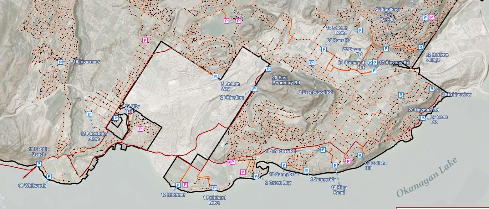
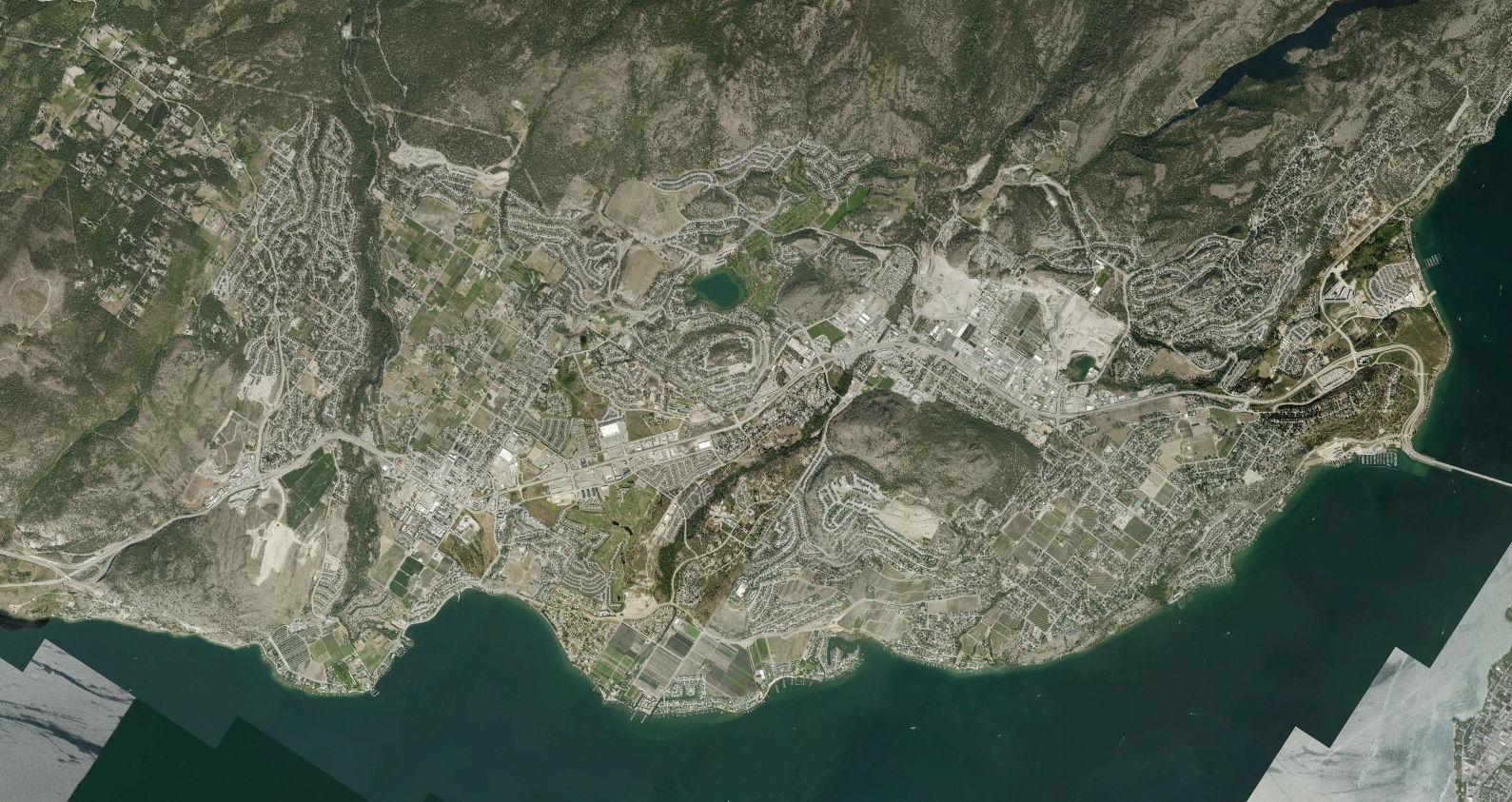
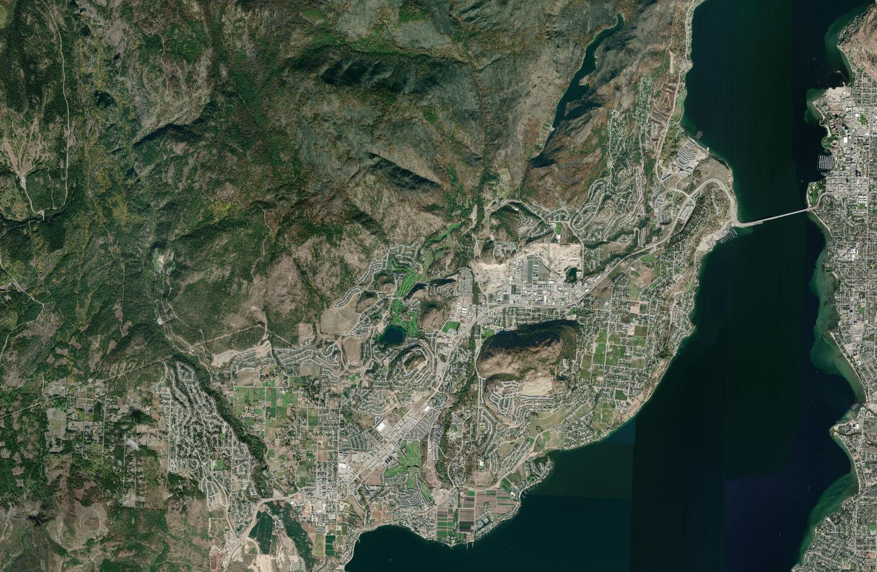
All sanitary flows collected within the City’s system is conveyed to the Westside Regional Wastewater Treatment Plant (WWTP), operated by the Regional District of Central Okanagan (RDCO). The City is responsible for the operation and maintenance of the local collection system, which includes smallerdiametergravitymainsandliftstationsthatfeedintotheregionalnetworkoperatedbytheRDCO.Several keytrunksewers,includingtheShannonLake,FirstAvenue,Westbank,GellatlyEast,andEastBoundary trunks form the backbone of the City’s collection system, conveying flows from various neighborhoods towardtheregionalinfrastructure.Thesanitarynetworklayoutcanbeseenin Figure 1.
ThesanitarycollectionsystemgenerallybenefitsfromtheCity’sfavorabletopography,whichallowsgravity flowthroughmuchofthenetwork.Liftstationsarestrategicallylocatedinlow-lyingareastoconveysanitary flowsto higher elevations, where itcanagainflow bygravity towardthe WWTP. AstheCitycontinues to experience growth, system improvements and capacity upgrades, particularly within older service areas, will be required to accommodate additional flows, maintain service levels, and ensure compliance with regulatorystandards.
SomeofthekeybackgrounddocumentsthatMcElhanneyhasreceivedinclude:
CityofWestKelownaWorksandServicesBylawNo.0249,2018;
CityofWestKelownaOfficialCommunityOfficialCommunityPlan(2020)
CityofWestKelownaInfillHousingStrategy(2024)
MasterMunicipalConstructionDocuments(MMCD)DesignGuidelineManual(2022);
CityofWestKelownaSanitarySewerUtilityMasterPlan(Stantec,2014)
NodocumentationfromtheRDCOwasfoundtoberelevantorapplytotheassessmentoftheCity’ssanitary collectionsystem.
McElhanneyalsoreviewedtheCity’s2020EmergencyResponseManual–CollectionSystemsdocument. Feedbackonupdatestothedocumenthasbeenprovidedseparatelyfromthisdocument.






The evaluation completed and recommendations made are in accordance with the requirements of City BYLAW No. 0249 and the Master Municipal Construction Documents (MMCD) Design Guideline Manual (2022).TherelevantsanitarydesigncriteriausedfortheevaluationoftheCitysanitarycollectionsystemis presentedin Table 1
Table 1: Sanitary Sewers Design Criteria
ResidentialPopulationDensity
Single-Family
Multi-FamilyLow
Multi-FamilyMedium(3storey)
Multi-FamilyHigh(4-12storey)
MobileHome
Non-ResidentialPopulationDensity
Industrial
Institutional
3persons/unit 2persons/unit 2persons/unit 2persons/unit 2persons/unit
Commercial 50persons/ha 50persons/ha 75persons/ha
PeakingFactor(PF)1
InflowandInfiltration(I&I)
PipesNotinWaterTable
PipesinWaterTable
OldPipes
GravitySewerRoughnessCoefficient(n) (Manning’sFormula)
5,000litres/hectare/day
8,000litres/hectare/day 10,000litres/hectare/day
0.011PVC 0.013Concrete
ForceMainFrictionCoefficient(C) (Hazen-WilliamsFormula) 120forPVC 145(forrecalculations)
MinimumPipeDiameter
Residential
CommercialandIndustrial 200mm 250mm
PipeCapacity(d/D) 80%(MMCD)
FlowVelocities2
Min0.60m/s;Max3.0m/s
Min1.0m/s;Max3.5m/s
MinimumGrade3 1.0%
SewerCoverDepth
Notes:
Min1.2m;Max5.0m
1). Where P is population, rounded to the nearest thousand and f isresidential factor. This is appliedto the average flow based on typeof residential.
2). There is nomaximum velocity for gravity sewer main, however, consideration must begiventoscour problems and the dynamic loading on manholes where the flow exceeds 3.0 m/s.
3). The minimum gradefor allpipes must be 1.0%, unless restrictedby surfaceconditions, the grade of any sewer is governed by the minimumvelocity requiredof 0.60m/s.
TheriskassessmentcompletedfollowedtheCity’s Risk Framework: Asset Level (Citywide,August2024) guidelinesforsanitaryinfrastructurebyevaluatingtheprobabilityoffailure(PoF)andtheconsequenceof failure(CoF).However,somerevisionsweremadetotheconsequenceoffailurecriteriaforbothlinearand lift station assets, and the operation & maintenance (O&M) and capacity criteria were added to better distinguishandprioritizeupgraderankingsbetweenbothlinearpipesandliftstations.
Astandardized riskmanagementapproachwasused toevaluatetheoverallrisk ofeachsanitarysewer. TheriskscoreforeachpipesegmentiscalculatedbycombiningthePoF,CoF,andacapacityscorederived fromthehydraulicmodeling.Thecapacityscorerangesfrom 1 (adequate)to 3 (undersizedunderexisting conditions),asinformedbythemodelresultspresentedin Sections 4 and 5
Risk = PoF x CoF + Capacity
The PoF for the sanitary sewer assets is calculated using a combination of weighted lifecycle (age and material)andconditionscoresbasedontheavailableCCTVinspections.Eachpipesegmentisassigned a PoF score from 1 (very low) to 5 (very high). The PoF for each pipe segment is calculated using the followingformula:
PoF = (Age and Material Score x 40%) + (Structural Condition Score x 60%)
Table 2 summarizes the scoringcriteriaandweightingschemaused todetermine the PoF for each pipe segment.
RemainingLife
≥80%remaininglife–1–VeryGood
≥60%remaininglife–2–Good
≥40%remaininglife–3–Fair
≥20%remaininglife–4–Poor
<20%remaininglife–5–VeryPoor
TheusefullivesforthedifferentpipematerialsusedinthePoFevaluationarelisted Table 3
Table 3 Pipe material useful life
TheCoFforsanitarysewerassetswasbasedonthe Risk Framework: Asset Level (Citywide, August 2024) guidelines for linear wastewater assets. However,somechanges to thescoring criteria around pipe size were made to provide a more accurate representation of pipe criticality based on flow (noted as level of service) as opposed to relying solely on pipe diameter for several of the criteria categories (economic, healthandsafety,andenvironmental).Eachcriteriawasscoredonthesame 1 (verylowimpact)to 5 (very highimpact)scale,weighted,andsummedtogethertodetermineanaggregatedCoFscoreoutof 5 Table 4 lists the scoring criteriaand weighting schema used in this assessment to determine the CoF for each pipesegment.
Table 4: Linear pipe CoF scoring criteria
DirectFinancial (ClassDreplacementcost; incl.material, 15%construction, 10%engineering, 30%contingency)
≤$20,000–1–VeryLow
≤$50,000–2–Low
≤$100,000–3–Moderate
≤$250,000–4–High
>$500,000–5–VeryHigh
≤1L/s–1–VeryLow ≤10L/s–3–VeryLow >10L/s–5–VeryHigh
ThefollowingformulaisthenusedforcalculatingtheCoFforlinearassets:
CoF = Sum(Criteria Score x Weighting)
2.2.2.Lift
Liftstationswereevaluatedusingariskassessmentapproachsimilartothatappliedtothelinearsanitary system,with additional consideration for operations and maintenance (O&M) factors and pump capacity. Theoverallriskscoreforeachliftstationwascalculatedusingthefollowingformula:
Thefollowingkeyelementswereconsideredwhenassessingtheoverallconditionandperformanceofeach liftstation:
Equipmentconditionandremainingservicelife,includingmechanical,structural,electrical,control, andinstrumentationcomponents.
Pumpingcapacityisevaluatedrelativetoexistingandprojectedflowconditions.
O&Mrequirements,includingtheeaseofaccessandsafetyconsiderationsforoperators.
Financial,economic,environmental,emergencyprovisions,andlevelofserviceimpactsassociated withapotentialfailure.
The PoF assessment evaluates the probability that a lift station or its components will fail. This score is basedontwoprimaryfactors:conditionindexandusefullifeconsumed.
The condition index, weighted at 60%, rates each asset and component (suchas pumps, piping, valves, andelectricalcontrols)onascalefrom1(verygood)to5(verypoor),basedonobservedphysicalcondition andperformance.Theseratingsarenormalizedtoavaluebetween 0 and 100
Theremainingservicelife,weightedat40%,calculatesthepercentageofexpectedservicelifeconsumed foreachcomponent,withhigherpercentagesindicatingincreasedriskoffailure.ThePoFscoringisoutlined in Table 5
UsefulLifeConsumed
≤20%lifeconsumed–1–VeryGood
>20%lifeconsumed–2–Good
>40%lifeconsumed–3–Fair
>60%lifeconsumed–4–Poor
>80%lifeconsumed–5–VeryPoor
TheCoFassessmentevaluatesthepotentialimpactresultingfromaliftstationfailure.Eachliftstationwas evaluated as awholefor its consequence of failure from a community perspective, incorporating several criteria each assigned a specific weight, as summarized in Table 6. The CoF weighting schema was developedthroughdiscussionwithCitystaffwithanelevatedweightingassignedtoEmergenceProvisions toreflectOperations’preparednessduringemergencies,suchasoverflowspillstotheenvironment.
Table 6: Lift station CoF scoring criteria
DirectFinancial (Replacement Cost)
Economic (LandUse)
Environmental (Proximityto WaterBody/ESA, FloodRisk)
Assessesthefinancial impactbasedon replacementcost
Evaluatestheproportionof residential,commercial,and industriallanduseinthe catchmentarea,withhigher populationdensities increasingtheconsequence score
Ratesthesensitivityofthe locationtowaterbodiesand floodrisk
Emergency Provisions
Considerstheavailabilityof backupgenerators, emergencystorage,site access,etc.forresponse effectivenessinan emergency
ProximitytoWaterbody 500+m 1 150-500m 2 75-150m 3 30-75m 4 0-30m 5
FloodRisk
LS>1maboveFCL 1 LS<1maboveFCL 2 LSbelowFCL 5
1
5
EmergencyStorage 60+minutes 1 45-59minutes 2 30-44minutes 3 15-29minutes 4 0-14minutes 5
SiteAccess Siteisfenced 1 Nofencing,lowtrafficarea 3 Nofencing,highusepublicarea 5
The CoF score for each lift station is calculated as a weighted sum of these criteria, with higher scores indicatingmoresevereconsequencesandhighercriticality.
Operations & Maintenance assessment evaluates operational safety and maintenance requirements for eachliftstation.TheO&Mscoreisbasedonratingsfor:
Confinedspaceentryrequirements
Functioningaccessequipment
Safetygratesonhatches
Sitelightingandsecurity
Each factor is rated from 1 (low risk) to 5 (high risk), with higher scores indicating greater operational challenges,aslistedin Table 7.TheO&Mscoreistheaverageoftheevaluatedcriteriaandnormalizedon ascaleof0-2.
Capacityassessmentevaluates whether eachliftstationcan adequatelyhandlecurrentandfutureflows. Thepercentageofdesigncapacitycurrentlyandprojectedtobeusedisscoredonascalefrom0to5,as listedin Table 8,withstationsoperatingnearorabovetheirdesigncapacityreceivinghigherscores.This approachhighlightsstationsatgreaterriskduetolimitedsparecapacity.
Thecapacityscoreistheaverageofthetwocapacityscenarioscores(existingandfuture)andnormalized onascaleof0(highavailablecapacity)to3(noavailablecapacity).
Sanitaryloadingwascalculatedforparcelwithinthemodelbasedonthefollowinginputsandassumptions.
Unitpopulationestimateswerederivedbasedonthenumberofresidentialunitsandtheaverage populationperunit.
The number of residential units per parcel was determined using the City’s address database in conjunctionwithparcelmappingdata.
Industrial, Commercial, and Institutional (ICI) loading densities were estimated using building footprintareascombinedwithpopulationequivalentsperhectare.
Population sanitary loading rates and diurnal flow curves were applied to generate Peak Dry WeatherFlow(PDWF).
Infiltration and Inflow (I&I) rates were then applied to the PDWF to estimate Peak Wet Weather Flow(PWWF).
The calculated flows for each parcel were assigned to the nearest upstream junctions in the modelednetwork.
PopulationprojectionsforthefuturescenarioswerebasedontheCity’sOCP,releasedin2020.TheOCP outlinestwoapproachestogrowthforecasting.
1. Anaturalgrowthrateof1.5%peryear,representingsteadypopulationincreaseacrossestablished neighborhoods.
2. Aproject-basedgrowthscenario,wheredevelopmentareasareidentifiedforhigh-densityorlargescaleresidentialexpansion.
Theproposeddevelopmentareasareprimarilysituatedwithindistinctsub-basinsofthesanitarynetwork, with only two developments sharing overlapping sanitary catchments. Incorporating all proposed developmentsintothemodelenablesassessmentofthesystem’sultimatebuildoutcapacity,evenifonlya portionoftheseprojectsarerealized.Giventhatthedevelopmentsarelargelyindependent,thisapproach isnotexpectedtoresultinexcessiveloadingatanysinglepointwithinthesystem.Whilethismethodology produces a modeled population that exceeds projections based on the natural growth rate of 1.5%, it providesamorecomprehensiveunderstandingofthesystem’slong-termperformanceunderpotentialfullbuildoutconditions.Thefollowingscenarioswereanalysed.
The2045scenariorepresentsfullbuildoutofallplanneddevelopments.
The2035scenariorepresentspartialbuildout,oramid-termdevelopmenthorizon.
The2025scenarioreflectsexistingconditions,calibratedtocurrentpopulationestimates.
The2024populationwasobtainedfromBCStats(40,093residents).Usingahistoricalannualgrowthrate of 2%, the 2025population was estimated at 40,900. Futurepopulationprojections were then developed basedonbothnaturalgrowthandproject-baseddevelopmentassummarizedin Table 9.
Table 10 and Table 11 outline both the proposed OCP development areas and the anticipated neighborhoodinfillasoutlineinthe2024InfillHousingStrategyunderfuturegrowthscenarios.
Table 11: Future neighbourhood infilling based on the Infill Housing Strategy
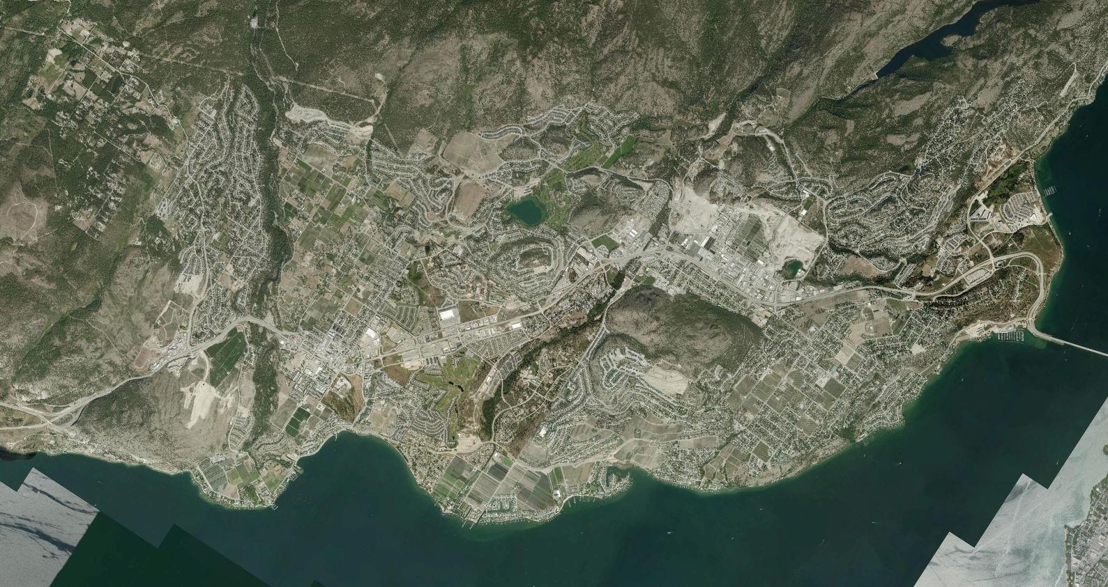
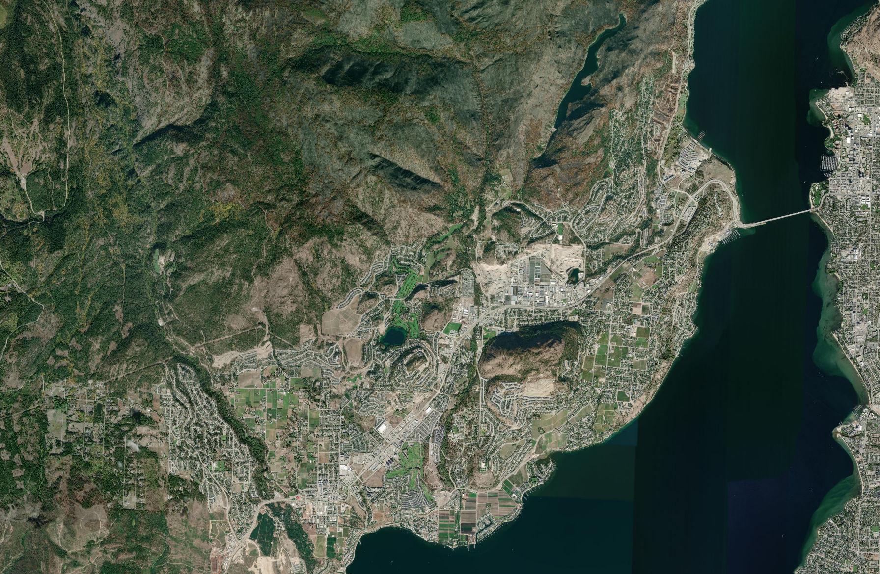
Populationestimates were based on anaverageoccupancy rateof 2.6 persons per dwelling unit. Within themodel, project-based populationswereappliedat onlya select numberofnodes torepresent higherdensity developments, while infill populations were distributed evenly throughout each neighborhood to lowerdensitygrowthprojectsgrowth.Thelocationofthemajordevelopmentscanbeseenin Figure 2

3.1.
The condition and performance of the City’s lift stations were evaluated to identify infrastructure deficiencies,capacityconstraints,andoperationalrisks.Eachliftstationwasreviewedbasedonavailable record drawings, recent inspection or maintenance records, discussions with Operations staff, and hydraulicmodelsimulationswhereapplicable.Fieldassessments ofeachliftstationwerenotcompleted, butratheradesktopassessmentofexistinginformationwascompleted.
Thelocationofallliftstationscanbeseenin Figure 1
3.1.1.Data Sheets
Datasheetswerepreparedforeachliftstationtosummarizekeyinformationobtainedduringthedesktop investigation.EachdatasheetconsolidatesallrelevantdetailsextractedfromCity-provideddocumentsand includesthefollowingelements.
Generalidentificationandconfigurationoftheliftstation.
Hydraulicstoragecapacityandpumpmechanics,includingforcemaincapacity.
Flowrecords/hydraulicmodellingsimulationestimatesandpumpcapacity.
Electricalandcontrols.
Floodrisk.
Replacementvalue.
Catchmentareamap,recorddrawing(s)ifavailable,andpumpperformancecurveifavailable.
Reviewcommentsandrecommendedactions/upgrades.
Riskandupgradepriorityrating.
Theliftstationdatasheetscanbefoundin Appendix B
3.1.2.Risk
Allliftstationswereevaluatedusingtheriskmodeloutlinedin Section 2.Basedoneachliftstation’sfinal risk score, the upgrade priority was determined, the result are summarized in Table 12. A detailed breakdownofeachliftstation’sriskscoringcanbefoundin Appendix C. Recommendedupgradesforeach liftstationareidentifiedinthedatasheetslocatedin Appendix B.
Upgradeprioritiesaresubjecttochangebasedonoperationalneedsidentifiedwithineachcorresponding datasheet.
The City’s linear sanitary sewer network is comprised of approximately 224,600 m of gravity mains and 14,902mofforcemainsinavarietyofpipematerialstotallingapproximately239,561m,assummarizedin
Table 13 and Figure 3. Most of the City’s sanitary sewer network is comprised of PVC, with smaller amountsofAC,concrete,HDPE,andunknownmaterials.
Table 13: Existing Sanitary Sewer Material
PercentageofSanitarySewerPipesbyMaterial
The GIS data provided by the City indicates that the majority ofthe linear sanitary network was installed between the late 1980s and early 2000s, as illustrated in Figure 4. Additionally, 3,216 m of pipe are documentedwithunknowninstallyears.
QuantityofPipeInstalledperYearbyMaterial
The City provided PDF and video CCTV inspection information for 30 pipe segments, totalling approximately2,669m(justover1%oftheCity’sgravitysewernetwork),whichallindicatedthepipeswere inverygoodcondition,asshownin Figure 5
InadditiontotheCCTVinspectiondata,Citystaffindicatedthatseveralsectionsofgravitymainareknown tohaveoperatingdeficiencies.
WittRoadBelly
RossRoad
RidgeBoulevard
GlenwayRoad
HorizonDrive
ReeseRoad
Amongtheareaswithidentifieddeficiencies,about410mofRossRdhasundergoneCCTVinspectionand hadonerecordedmediumjointseparationwithalowseverityscoreonpipesegment3003547at77.25m downstreamofmanholeIP15.AdditionalCCTVinspectionsarerequiredfortheremainingsanitarymains alongRossRdandotherlocationstodetermineifthereareanystructuraloroperationalissuesthatrequire rehabilitationormaintenance.
Wherestructuralconditioninformationwasn’tavailable,thePoFwascalculatedentirelybasedonageand material. Figure 6 illustratesthePoFprofilefortheCity’slinearsanitaryassets,withlengthandpercentage oftheCity’slinearsanitarynetworkforeachPoFscorecategory.
AmapshowingthePoFscoresforeachsanitarymaincanbefoundin Appendix D
Figure 7 illustratestheCoFprofilefor theCity’slinearsanitaryassets,withlengthandpercentageofthe City’slinearsanitarynetworkforeachCoFscorecategory.
AcompletelistingofCoFscoresforeachsanitarymaincanbefoundin Appendix E.
Figure 8 illustratestheriskprofilefortheCity’slinearsanitaryassets,withtotalestimatedreplacementcost andpercentageoftheCity’slinearsanitarynetworkforeachriskcategory.
Acompletelistingofriskscoresforeachsanitarymaincanbefoundin Appendix F.
Table 14 identifiesthelinearsanitaryassetswiththehighestrisk,asdeterminedbytheassessment framework.
Table 14: Linear Asset Risk Assessment
Unitratestodeterminethereplacementcostforlinearsanitaryassetsarelistedin Appendix G.
ThecompletelinearsanitarysewerassetinventorywithPoF,CoF,capacity,andriskassessmentresults canbefoundin Appendix H.

4.1.
The model for the proposed sanitary sewer system was originally developed in 2014 using InfoSWMM software.However,asInfoSWMMisnolongeractivelymaintained,thedecisionwasmadetotransitionthe existing model data to PCSWMM version 7.7 to avoid potential compatibility or functionality issues. This program is an adaptation and enhancement of the United States Environmental Protection Agency’s (USEPA) Stormwater Management Model (SWMM) version 5.2. PCSWMM was developed by Computational Hydraulics International (CHI) as a combination hydrology-hydraulic model and is well known and widely used by civil engineering practitioners. The transition allows the model to remain functionalandalignswithcurrentindustrystandards.
Themodelwasrunfora48-hourperiodtoensurethesystemwasrunningatfulldemandandevaluatethe operation during peak demands. The Dynamic Wave methodology was selected for this assignment to effectively account for backwater effects. The model was set up to simulate the natural sanitary diurnal curvesbasedonobserveddata.Theobserveddatawasalsousedinthecalibrationprocess.
Theoriginalmodel includedapproximately 190 km of sanitarysewersbutexcluded liftstations andforce mains.Adetailedreviewoftheconvertedmodelwasconductedtoidentifyareasrequiringupdatestoreflect currentnetworkconfigurations,recentdevelopments,andmissinginfrastructure.Bulksanitaryloadinghad beenimplementedpreviously,meaningthatanunknownnumberofhomeswereloadingtoasinglenode. Thisapproachmakestheprocessofupdatingandalteringloadingrateswithinthemodelchallenging. To confirm sanitary loading reflects current conditions, a parcel-based loading approach was implemented. This method establishes a direct link between parcels and sanitary loading at nodes, simplifying future updates.
Bill44(2023)implementedbytheprovinceallowsforsmall-scales,multi-unithousingonparcelsthatwere previouslymarkedfor duplexes orsingledetachedhomes.Thiscouldleadtoarapidlychanginghousing landscape that falls outside of the anticipated development plans that the CIty has put forth. The parcel based loading method will allow for quick updates and additional transparency of the sanitary loading comingfromeachparcelwithintheCity.
Toupdatetheoriginalsanitarymodel,itwasnecessarytoincorporatenewinfrastructureconstructedsince 2014 into the current working model. To address data gaps within the system, the following hierarchy of logicwasapplied.
Ifamissinginvertelevationwasassociatedwithapipeconnectedtoanotherwithaknowninvert, itwasassumedthatbothsharedthesameelevation.
If the pipe slope was available, invert elevations were estimated relative to the nearest known elevationusingtherecordedslope.
Ifneitherconditionwasmet,recorddrawingsandinformationavailablethroughtheCity’sGISportal werereviewedtodetermineappropriateelevations.
Wherediscrepanciesoccurredbetweendifferentrecordeddatasets,pipesegmentsweremanually adjustedtoallowforcontinuousandrealisticflowconveyancethroughoutthenetwork.
Wherealloftheabovestepsfailed,sectionsweremarkedasinactive,andwerebypassedwithin themodel
Table 15: Network Alterations Summary
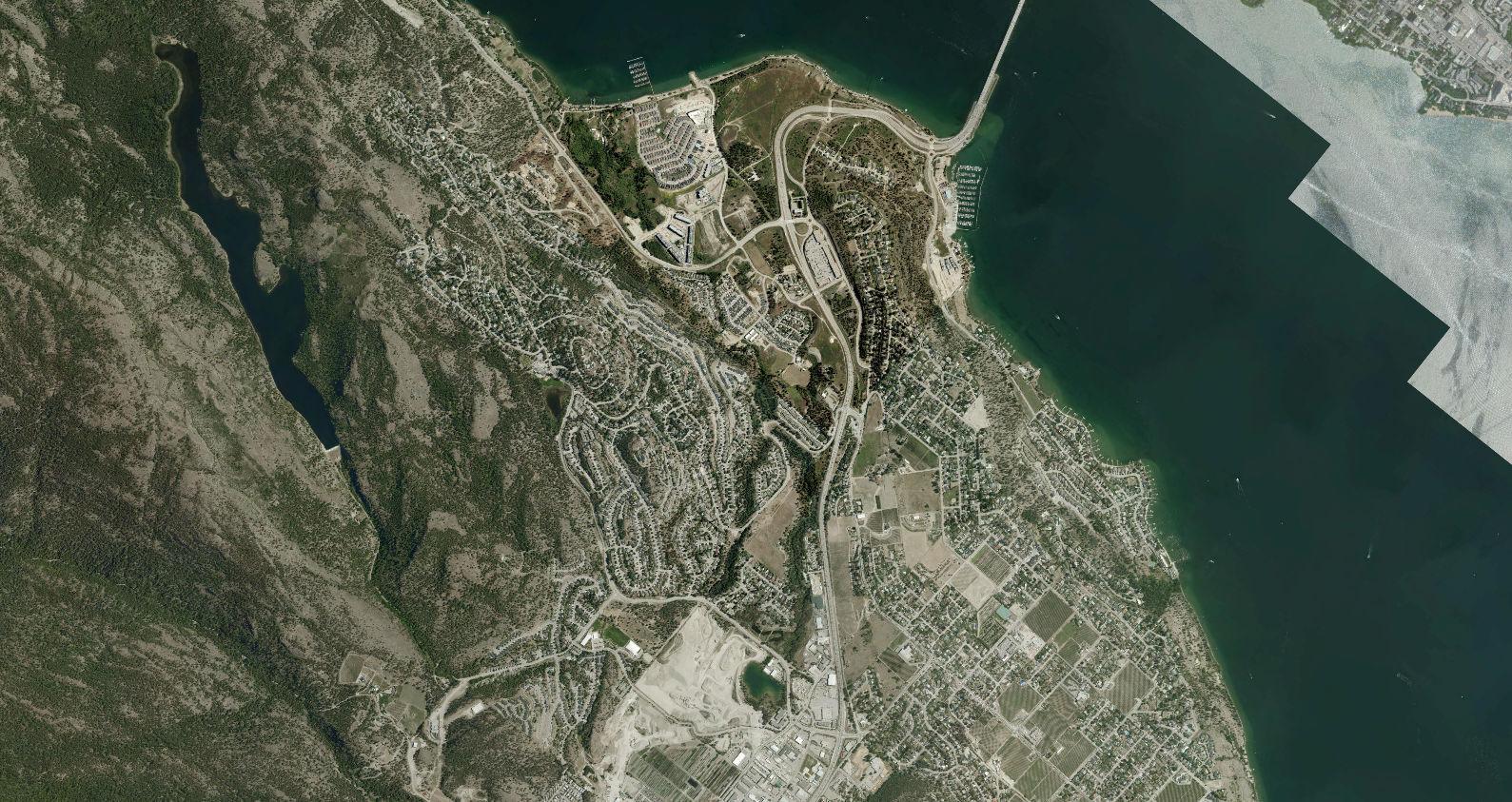
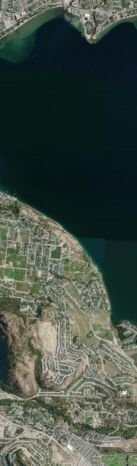
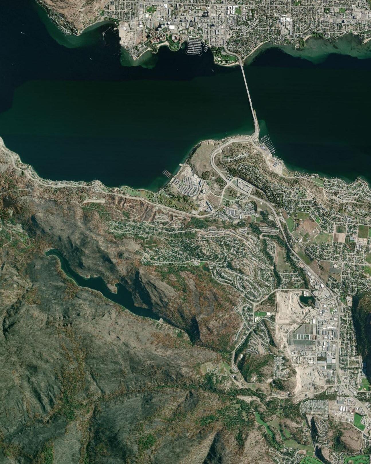
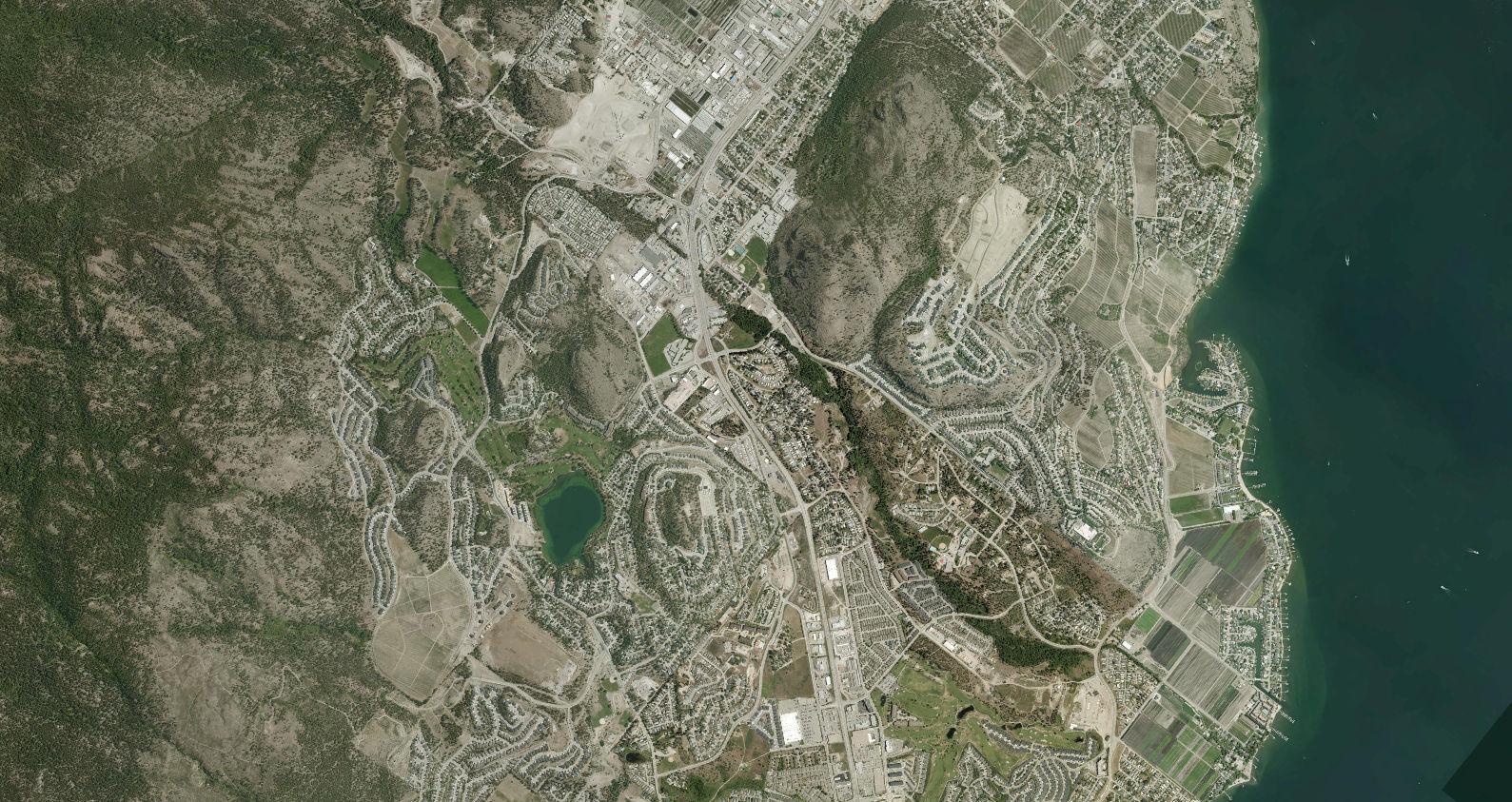
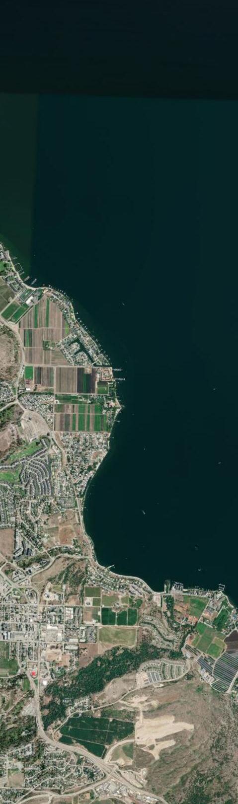
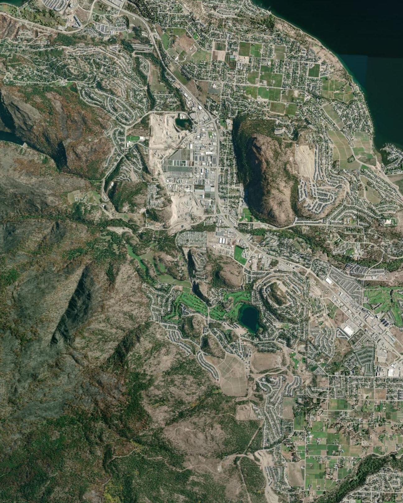
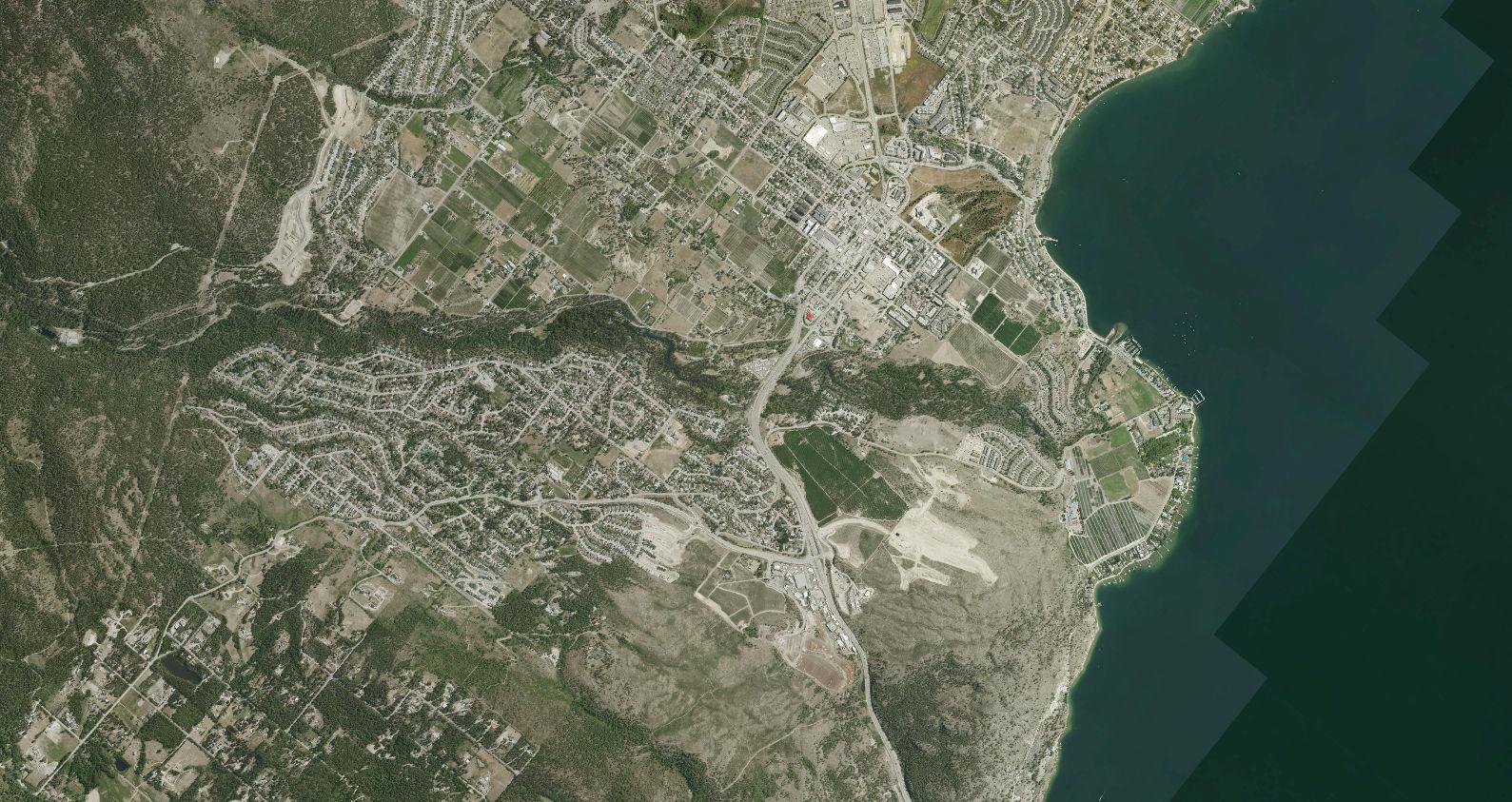
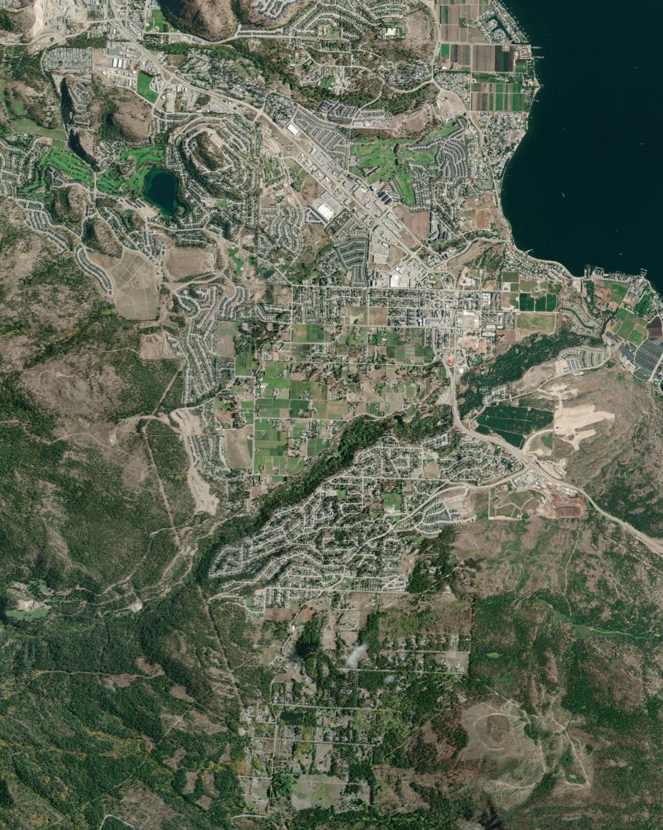
The model updates completed allow for consistent hydraulic connectivity and eliminated previous issues where gravity mains were positioned below their downstream connections. These improvements were achievedthrough acombinationof availabledata,andmanualadjustments.The new areasincorporated intothesanitarysewermodelcanbefoundin Figure 9



Flow monitoring was conducted at five locations across the City. Monitoring points were selected by the CitywithinputfromMcElhanneyandwereequippedwiththeSmartCovermonitoringSystem.
ThePeakDryWeatherFlow(PDWF)calibrationperiodwasdefinedasSeptember2–8,2025,representing adryperiodwithnorecordedrainfallfollowingastretchofminimalprecipitation.Thistimeframewaschosen becauseobservedflowsreflectedtypicalsanitaryloadingconditionswithoutrainfallinfluence.
Theresultsofflowmonitoringduringthedryweatherperiodcanbeseenin Table 16
Table 16: Daily sanitary volumes at monitoring locations during the dry weather period
Witt Road MonitoringMultiunit apartmentbuildings
Tocompletecalibrationofthemodelunder dryweatherflow(DWF)conditions,thefollowingadjustments weremadetothestandardinputparameters.
ICI(Industrial,Commercial,Institutional)loadingratesweremaintainedatstandardvalues.
The population ratios between single-family homes (SFH) and multi-family homes (MFH) were adjustedslightlytobetterreflectobserveddata—3.1personsperSFHand1.86personsperMFH.
Theaverage dailysanitary loadingrateacrossmost of the modelwas 230 L/person/day.For the Shannon Lakearea,theratewas increasedto 305L/person/dayto accountfor larger residential homesandhigherwaterusagepatterns.
This represents a minor increase from the previous model’s 220 L/person/day. The results of the PDWF calibrationaresummarizedin Table 17.
A well-calibrated hydraulic model is generally expected to achieve agreement within ±10% between observedandsimulatedflows.Thesystem-wideaveragedeviationof5%indicatesthatthemodelprovides aslightlyconservativerepresentationofsystemperformance.
TocalibratethePWWF,flows at eachstation were analyzed inconjunction with recorded rainfall data to identifypotentialrainfallresponses.Overall,thesystemdemonstratedminimalrainfallsensitivity,withonly theEastBoundaryLiftStationshowingaminorincreaseduringwetweatherevents.Thiswasduringa16 mmrainfall event onJune 20, 2025, lasting approximately 12 hours, which is equivalent to a 1-in-2-year returnperiodstorm.Otherstationshadaveryminorresponseduringthisevent.
AlthoughRTKrainfallcalibrationwasperformed,theresultingI&Iresponsewasnotclearlyevidentatmost monitoringlocationsexceptforEastBoundary.Basedontheobserveddata,I&Iinfluenceatthemonitored locations was found to be minimal. The RTK-derived response was lower than the standard design I&I parameters.Thereforetomaintaindesignconditions,thestandardI&Irateof5,000L/day/hawasadopted formodelingthePWWFscenario.Thisallowsthesystemtobetestedinamoreconservativemanorand willtakeintoaccountanyfuturedeteriorationinthesystemthatmayincreaseI&I.Thesestandardratesare expectedtobeaboveI&Iratesexperiencedinthesystemandthusaclimatechangecorrectionforfuture eventswasnotconsideredwithinthemodelingprocess.
If excessive I&I is noted at any lift stations during periods of high rainfall or elevated lake levels, then additional investigation can be performed by undertaking smoke tests or CCTV inspections within the upstreamgravitymainsorinvestigatingtheliftstationwetwellstructurestohelpidentifythesourceofthe I&I.
ThreemodelingscenariosweredevelopedtorepresentdifferentstagesofprojectedgrowthwithintheCity.
2025Model(CurrentConditions)
2035Model
2045Model
ThesescenariosweredevelopedtosupporttheCityinstrategicinfrastructureplanningaspopulationand developmentcontinuetoexpand.The2025modelrepresentsthecurrentstateofthesanitarysystem,while the 2035 and 2045 models simulate system performance under the anticipated project-based growth scenario.

ThesanitarymodelwasanalyzedunderbothPDWFandPWWFconditionstoassesssystemperformance withrespecttominimumscourvelocities,maximumallowablevelocities,andoverallconveyancecapacity. Theseevaluationswereconductedforthecurrent(2025),2035,and2045scenarios.Forallmodelruns,it wasassumedthattheconnectiontotheRDCOsanitarytrunkmainoperatedatfullcapacity(100%)atthe downstreamboundarytorepresentaworst-casetailwaterHGLcondition.
5.1.1.System Velocity
Figure 10, Figure 11, and Figure 12 illustrate the modeled velocity distribution within the gravity sewer networkforthethreeplanninghorizonsunderPDWF.Themaximumvelocitythresholdwasassessedunder PWWFconditions,whiletheminimumvelocitythresholdwasevaluatedunderPDWFconditions.
Table 18 summarizes the number ofpipesthat do notmeetvelocity-relatedperformancetargets ineach scenario.
Table 18: Summary of velocity issues within the sanitary system
ThePDWFconditionwasusedtosimulateminimumpipevelocitiesduringextendeddryweather,whenI&I contributionsareminimal.Thisanalysisidentifiessegmentsthatdonotachievetheminimumself-cleansing velocityof0.6m/s.
Results indicate that a majority of (>50%) the network does not meet cleansing velocities under PDWF conditions. This is primarily attributed to flat grades (slopes below 0.6%) and low upstream contributing areas, which reduce flow depth and velocity. A small number of pipe segments experience excessive velocitiesduringPWWFevents,exceedingrecommendedlimits.
Infuturescenarios,increasedsanitaryloadingfrompopulationgrowthisexpectedtoreducetheextentof low-velocity segments, while slightly increasing the frequency of high-velocity occurrences. This shift reflectsthesystem’sresponsetohighersanitaryflowsoverall.





The model was analyzed under PWWF conditions to assess system capacity and potential surcharge conditions throughout the gravity network. The capacity constraints withinthe sanitary network can been seen in Figure 13, Figure 14, and Figure 15. This analysis identifies pipe segments that approach or exceedthetargethydrauliccapacity(d/D<80%)underthethreemodelingscenarios.
Threeareaswithinthesanitarynetworkwereidentifiedashavingcapacityconstraintsunderoneormore modelscenarios.Thesearesummarizedin Table 19 below.
forcemainsareundersized
Threelargeconsecutivebendscausethe systemtobackupbeforeenteringthelift station
TheHorizonDrivesectionrepresentsthe onlyareaofimmediateconcernundercurrent2025conditions, primarilyduetoinsufficientpipesloperesultinginreducedconveyancecapacity.TheEastBoundaryRoad andHighway97areasexhibitpotentialcapacitylimitationsunderfuturegrowthscenarios(2035and2045). These conditions are largely influenced by projected increases in sanitary flow from upstream developments, particularly within the Boucherie and Rose Valley growth areas which drain to the East Boundaryliftstation.The2045modelingscenarioassumesfullbuildoutofthesedevelopments,inaddition to infill growth within existing service areas. Given these future development assumptions, capacity improvements in these areas should be monitored and timed in accordance with actual development progression.Upgradesshouldbeconsideredwhenlocalpopulationsandassociatedsanitaryflowsbegin toapproachlevelsrepresentedinthe2035and2045scenariosfortheseneighborhoods.
The 2014 Sanitary Master Plan identified several capacity concerns not reflected in the current model, including Gorman Road, Horizon Village Lift Station, West Kelowna Estates, Gregory Road, and the Highway 97 crossing. These discrepancies are primarily due to differences in capacity threshold criteria and updated population forecasts. In 2014, a 60% capacity threshold was used to identify potential
upgrades,whereasthecurrentanalysisfollowstheMMCD-recommended80%threshold.ThecurrentOCP doesnotshowanymajordevelopmentsplannedupstreamofthesepreviouslyoutlinedareas.Theupdated model therefore indicates sufficient capacity under current and future conditions; however, should significantnewdevelopmentsbeproposedupstreamoftheseconnections,re-evaluationofcapacitywillbe necessarytoconfirmadequacyunderrevisedflowprojections.
Preventivemaintenanceforsanitaryliftstationsandsanitarysewermainsiscriticaltomaintainingsystem reliability and protecting public health and the environment. These assets operate continuously under demanding conditions, and failure can result in prolonged service disruptions, costly emergency repairs, andenvironmentalcontamination.
Regularinspectionsandproactiveservicing,suchaspumpperformancechecks,electricalsystemtesting, andcorrosioncontrol,helpidentifyearlysignsofdeteriorationbeforetheyescalateintomajorfailures.By intervening at optimal points in the asset lifecycle, the City can extend equipment longevity, maintain operationalefficiency,and reducelifecyclecosts.Preventive maintenancealsosupportscompliancewith regulatorystandardsandmitigatesrisksassociatedwithhealth,safety,andenvironmentalimpacts,making itanecessityofsustainablewastewatermanagementstrategies. Table 20 providesalistofrecommended preventivemaintenancetasksandfrequenciestoensuretheCity’swastewaterassetsreachtheiroptimal lifecycle.
Table 20: Recommended sanitary system O&M tasks and frequencies
As noted in Section 3.2, the following areas are known to have operating deficiencies and should have CCTVinspectionscompletedtounderstandanystructuraloroperatingissues.
WittRoadBelly
GlenwayRoad
RossRoad
HorizonDrive
RidgeBoulevard
ReeseRoad
Areaswithlowslopeandvelocityshouldalsobeprioritizedformainflushingandcleaningprogrammesas theseareasareatahigherriskforsedimentationissues.Theseareasarehighlightedin Figure 10
A sound asset management approach for inspection planning includes aligning condition inspection programs with risk profiles. Figure 16 illustrates the total quantity of linear gravity and forcemains recommendedfor inspectionovertheshort(1-2years),medium(3-5years),andlongterm(5-10+years) basedonrisk.
ForcemainGravityForcemainGravityForcemainGravityForcemain InspectionInspectionInspectionInspection 1-2years3-5years5-10years10+years
High2,2673082,826
Moderate 8,9226,02760,4342,602
Low 1,45397,57755,8821,180
Rear yard easements are difficult to maintain and replace due to access issues. Residents often don’t understandthere is an existing easementandbuildover top.TheCity sanitarynetwork makesextensive useof statutory rights-of-way (SRWs). SRW often are establishedtoreduce the totalnumber of sanitary lines, to reduce length of runs, or provide collection points where topography does not allow for simple gravityconveyancethroughroadwayrights-of-way’s(ROW)
Atotalof373sanitaryconnectionstraversingresidential,commercial,industrial,andagriculturallandswere identified.Connectionslocatedentirelywithinpubliclands,suchasparksandschools,wereexcludedfrom thisassessment,asaccessintheseareasisgenerallylessconstrained.Theremainingconnectionswere classified as either service lines, where the primary function is to provide gravity collection for nearby properties, or cross-through connections, where the primary purpose is to convey sanitary flows through anSRWtoanotherestablishedROW.
The sanitary network was reviewed to identify SRW crossings that could potentially be eliminated with minimaleffort.Assummarizedinthefollowingtable,47SRWgroupingswereidentifiedascandidatesfor relativelystraightforwardprojectsthatcouldremoverelianceonSRWs.EliminationoftheremainingSRWs wouldbeconsiderablymorecomplex.
AlistofallSRWscanbefoundin Appendix H andamapoftheirlocationscanbefoundin Appendix I
ReroutesouthtoMorningsideDrandGlenAbbeyPlintersection.
29 Service AppearstobeaccessforGlenrosaelementary.Alternativeaccess alongMcNamaraSt.
33 Cross-through ReroutetopassthroughROWconnectingInvernessRd,andWebber Rd.
43
Cross-through PossibilitytoregrademaintodrainnortheastonCopperRidgeDrive.
44 Service OpportunitytoestablishROWbetweenWebberRoadElementaryand GlenwayPark.
47 Cross-through RealigntopassthroughGlenwayRd.
49 Cross-through OpportunitytoestablishtoeliminateParcelpassthrough.
57
63
Cross-through OpportunitytoestablishaROW.
Cross-through ConnecttoexistingROWtothesouthwest.Upstreammayneedtobe regraded.
64 Cross-through RealignwithinHebertRdROW.
65
Cross-through EstablishanROWforlineoranewlinethroughPineridgePl.
153
154
CouldeliminateCross-throughrequirementbyregradingupstreamto drainwestonWildHorseDrtoexistingconnection.Backyard connectionsmaystillberequired.
Cross-through RegradeIronridgePltodraintoIronridgeRd,ortheROWonIronridge PL.
RegradetothenorthandconnecttothesanitarytrunkmainatVillage GreenWayintersection.
ReroutesoutheasttoParamountDraroundexitinghomeparcels
ReroutesoutheasttoCynCrestDraroundexitinghomeparcels
NewmainsalongPetersRdandMajorosRdcouldreplacecentral main.
Cross-through ReroutenortheastthroughexistingROW.Needanadditionalmain alongSandstoneDrfornewserviceconnections.
Cross-through NewMaindownUpperSundanceDrtoeliminateCross-through dependency.
Cross-through RerouteeastalongShamrockDr,andsouthwestalongOldOkanagan Hwy.
161 Service RealignwithinEnsignWayROW.
165 Service Industrialconnectionsmaybeabletoconnectintoexistingparallel sanitaryline.
167
173
175
Cross-through Relinetoeliminateminorparcelcross-through
Cross-through ReroutewestthroughexistingROWbetweenEastBoundaryRdand ChiefTomatElementary
Cross-through ReroutesouthwestonPritchardDr,andnorthonPritchardDrN.Would requirelinetobesecuredtobridge.Alternatively,reroutethrough NewportRdROW.
181 Cross-through PossibletoestablishROWonundevelopedproperty.
195 Service RealigntoVineyardDrROW.
197 Cross-through Reroutesouththroughroadwaytobypasshomes.
203 Cross-through EstablishROWifpossible.
218
Cross-through ReroutesouthwestdownRosealeeLn.
226 Cross-through RerouteeastdownRoseridgeCrt.
229 Cross-through ReroutesouthonRossRd,oreastthroughStevensRdROW.
237 Cross-through CrossHwy97atWestlakeRdandroutewestonHudsonRd
238 Cross-through ReroutewesttoconnecttoRosealeeLnmain.
245 Cross-through ReroutesoutheasttoSunviewDrmain.
266 Cross-through RegradeKellyDrsouthwesttoopenROW.
270 Cross-through ReroutethroughexistingROW.
290 Cross-through ReroutesouthonBoucherieRdtoSkylinerd
313 Cross-through ReroutewestthroughROWtoTealRd.
315 Cross-through RerouteeastdownHorizonDrtoexistingconnection.
Many of the service SRWs would require conversion to a low-pressure sewer system in order to be eliminated.Thiswouldrequireeachhometohaveanindividualgrinderpumpthatmovessanitaryflowinto themainsewerlineunderlowpressure,therebyroutingthesanitaryflowtosanitarymainslocatedwithin roadwaysratherthanbackyardSRWs.Theconstructioncostofthenewsystemwouldbetakenonbythe City before ownership of each pump would be passed onto the property owner who would handle maintenanceof thesystem.Thecostof implementing suchsystemswouldneedtobeevaluated against thecostofreplacingtheexistinggravityinfrastructurewithintheSRW.
Replacement and maintenance of the existing systems is complicated by surface works such as pools, sheds,patios,andhigh-finishlandscapingareclosetoorwithintheSRWs.Theseobstructionscomplicate access and increase the expense and difficulty of replacing or repairing the infrastructure. Access conditions are highly variable between individual SRW’s, and are likely to change over time, making it difficulttoreliablypredictfutureaccessibility.
ItisrecommendedthatSRWsapproachingtheendoftheirservicelifebeinspectedtoconfirminfrastructure condition and determine whether replacement is required. These SRWs along with nearby sanitary infrastructure should also be re-surveyed to ensure accurate and up-to-date records are available for planning and design purposes. Following these steps, a cost-benefit analysis should be undertaken to identifythemostappropriatecourseofaction.
A holistic assessment of the sanitary network should be completed prior to implementing any major changes, particularly in the southern Shannon Lake area and the West Kelowna Estates / Rose Valley neighbourhoods. This approachwould allow opportunities to address multiple SRWs simultaneously and betterunderstandhowproposedmodificationsmayimpactotherportionsofthenetwork.
Future development within the City presents opportunities to reduce reliance on SRWs by incorporating additionalroadwayrights-of-way.TheneedforSRWsisparticularlyprevalentincul-de-sacsanddead-end roads. Development planning should consider the inclusion of ROWs between residential parcels to improve utility access. Where feasible, these corridors could also function as pedestrian and cycling pathways,providingtheaddedbenefitofenhancedconnectivity.
Odouratsanitaryliftstationsisprimarilycausedbythebreakdownoforganicmatterinwastewaterunder anaerobic condition, which produces hydrogen sulphide (H2S), and other gases. The occurrence and intensity of odour depend on several factors, including wastewater temperature, retention time, flow patterns, and the presence of easily degradable organic material. Cycling of wet well levels can release trappedgasesresultinginnoticeableodours.Odourissuescanbeexacerbatedduringwarmermonthsas bacterialgrowthisencouragedbywarmertemperatures.
Tominimizetheproductionofgases,retentiontimeofsewageshouldbeminimized.Theoperatinglevels of the pumps in the wet well can be adjusted to reduce the resonance time of the system where odour issues are present. This should be assessed under thestations PWWF,so the system does not exceed the recommended pumping cycles during PWWF. Existing SCADA data can be referenced to determine performanceatstations.
15ofthe29liftstationsassedhadnoodourcontrolsystemsinplace.Ventscanbeinstalledtoallowfora controlledreleasedofgasesandcanbefittedwithfilterstoreduceodourfromtheventingprocess.Insome cases, improved ventilation, regular cleaning, and maintenance of the wet wells can also help minimize odourissues.ThreestationswerenotedasusingCalciumnitratechemicalinjectionstohelpreduceodour issues. This targeted intervention can be implemented for lift stations that are slated for replacement or upgrade, or during warm weather conditions. Detailed data sheets for each station are provided in Appendix B andprovidedetailsontheodourcontrolsystemsandfuturerecommendation.
Floodriskwasassessedbyproximitytoawaterbodyorifitwasbelowthefloodconstructionlevel.Eight liftstationareatelevationsclosetothelakefloodconstructionlevel,thoughonlytheWhitworthLiftStation islocatedbelowthefloodconstructionlevel.Beinglocatedclosetothelake,theseliftstationshaveahigh likelihood of being affected by the influence of the lake water levels. As the lake level increases, the groundwaterlevelwillbecomeelevatedwithinanareaofinfluenceadjacenttothelakeshore.Additionally, ithasbeennotedthatseveralliftstationshaveseenelevatedlevelsofI&Iwhenlakelevelsarehigherthan average.
Impacts to nearby bodies of water from a severe sanitary system failure were not assessed. A detailed investigation of the surrounding topography would be required to determine flow paths of any sanitary overflow. Timely maintenance and targeted upgrades, such as installing standby generators, paired with anup-to-datespillresponseplancanhelpmitigatethepossibilityofsanitaryfailureandresultingpotential environmentalimpacts.

7.1. IMPLEMENTATION STRATEGY
There are three proposed projects identified for the City to address the capacity concerns identified in Section 5.Asummaryoftheperformanceofthesanitarynetworkduringthe2045PWWF,andproposed upgradescanbeseenin Table 22.
Table 22: Proposed capacity projects and performance during the 2045 PWWF scenario.
AdditionalprojectswereproposedthroughdiscussionswithCitystaffandexaminingthesanitarynetwork.
Abriefdescriptionofeachprojectionisprovidedinthissection.
7.1.1.Horizon Drive near Faulkner Lift Station
TheproposedupsizingneartheFaulknerLiftStationwillmatchthediameterofthedownstreamconnection andprovideadditionalconveyancecapacityfortheresidentialareaservicedbythissection.Thelayoutand profileoftheproposedupgradeunderthe2045PWWFscenarioisshownin Figure 17
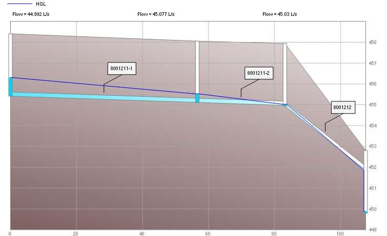
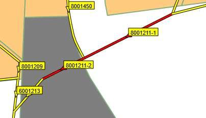
Figure 17: Layout and profile of Horizon Drive near Faulkner Lift Station during the 2045 PWWF.
Replacingthesetwopipesegmentsalsopresentsanopportunitytoestablishamoreuniformslopealong the profile. A steeper, more consistent grade will improve conveyance capacity, reduce the potential for sedimentdeposition,andhelpmaintainself-cleansingvelocitiesunderdry-weatherconditions.
The proposed upsizing along Highway 97 will match these gravity mains with the downstream diameter, improvingperformanceinanareathatconveysflowsfromboththe industrialdistrictandmanyupstream residential neighbourhoods draining toward the East Boundary Lift Station. The layout and profile are illustratedin Figure 18
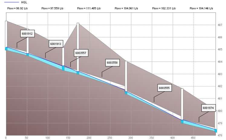
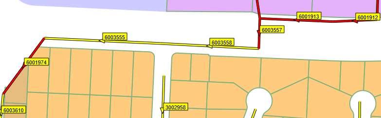
Increasingthepipesizesinthisareaallowsforlong-termperformanceasupstreamdevelopmentcontinues. Replacing all segments within this profile provides an opportunity to correct low-slope sections, thereby improving hydraulic grade, and lessening the risk of sedimentation. Realignment may also allow for the removalofexisting90°bends,furtherenhancinghydraulicefficiency.
The recommended upgrades at East Boundary Road involve upsizing the pipe segments immediately upstreamoftheEastBoundaryLiftStationtomatchthediameterofthedownstreamconnection.Thelayout andprofileareshownin Figure 19.
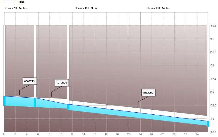
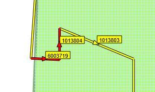
Streamlining the alignment to reduce the number of bends would further improve hydraulic performance andreduceturbulenceandminorlossesattheentrancetothismajorliftstation.
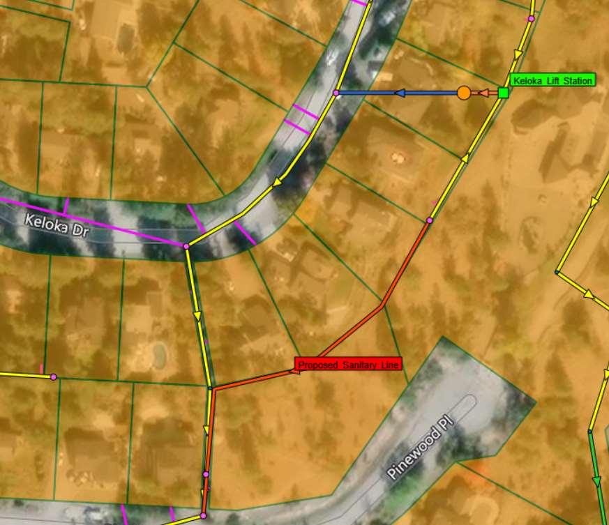
There is potential for the elimination of the Keloak Lift Station which would help reduce operation and maintenance expenses. The existing sanitary connection services 10 lots which produces relatively low flow.TheexistingsanitarysystemwouldberegradedtothesouthwesttomeetupwiththeROWbetween Keloka Dr and Pinewood Pl. This new line would likely require trenchless methods to install as the topography is not favorable for an open trench through this area. The proposed layout can be seen in Figure 20
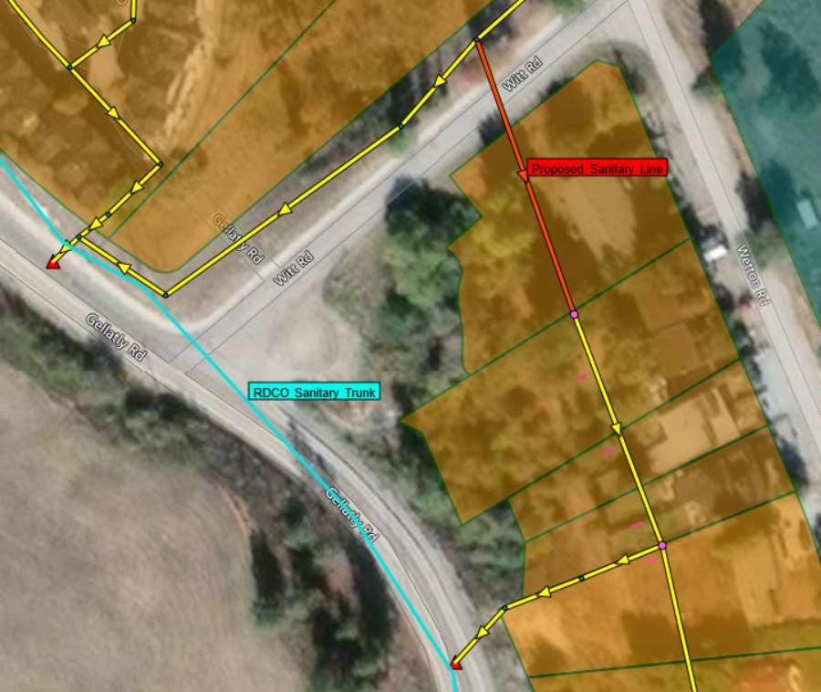
The Witt Road sanitary sewer currently connects to the private sanitary system serving the Providence Vista Housing developmentbefore discharging tothe RDCO trunk main. Performance issues have been observed at this location, attributed in part to the configuration of the existing connection. To address ongoing maintenance concerns, it is recommended that a new sanitary connection be constructed to conveyflowsfromtheWittRoadlinesoutheasttoanexistingCitysanitarymain.Theproposedlayoutcan beseenin Figure 21
7.1.6.Ensign Way Lift Station Bypass
EnsignWayliftstationservicesapproximately35homeswithinthesoutheastcorneroftheShannonLake neighbourhood.ThereislittleabilitytoregradethesanitarylinesintootherCItysanitarygravitymains.The liftstationwouldhavetobereplacewithalowpressuressystemorbyenteringanagreementtoconnect intothesanitarylinesofWTF.Acostbenefitanalysisshouldbeconductedtodeterminewhichoptionwould bemostviable.
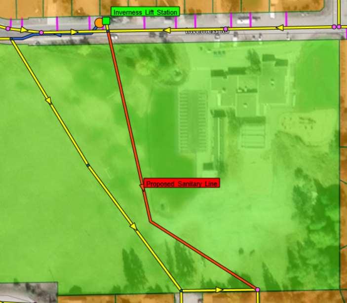
ThereisanopportunitytoeliminatethisliftstationbyinstallinganewsanitarylinethroughWebberRoad Elementary.Thiscouldreplaceorrunparalleltotheexistingsanitarymainbutwouldconnecttomanhole 2GT22insteadofLG20.Thisshouldallowforthesanitarylinetohaveasufficientgradewithoutachieving unreasonabledepths.Theproposedlayoutcanbeseenin Figure 22
Condition, capacity, and age and material influence when an asset if forecast to be replaced. Figure 23 illustrates the estimated renewal timeframe for each linear sanitary asset based on the probability and consequence of failure profile, totalled by length per year and replacement cost. One pipe segment (8001211 on Horizon Drive) is undersized in existing conditions and therefore recommended for replacementinthenext3-5yearsbasedonitsmoderateconsequenceoffailure.MostoftheCity’slinear sanitarysewermainsarelacking physicalconditiondataandthosethat havebeen inspected are in very goodcondition;therefore,themajorityofthelinearsanitarysewerassetsarerecommendedforinspection and forecasted for replacement based on their material-based estimated useful lives, including approximately1,629mofgravitymainthatisbeyonditsestimatedusefullife.Furtherrefinementof linear assetrenewalprioritizationwilloccurasfutureCCTVinspectionsarecarriedout.
$18,000,000
$16,000,000
$14,000,000
$12,000,000
$10,000,000
$8,000,000
$6,000,000
$4,000,000
$2,000,000
Figure 23: Forecasted Pipe Replacement by Install Year and Estimated Useful Life
Table 23 summarizestheestimatedreplacementcostperestimatedreplacementyearoftheCity’slinear sanitarysewerassetsbasedontheirprobabilityandconsequenceoffailureprofiles. $0
Table 23: Pipe renewal forecast based on probability and consequence of failure profiles.
Figure 24 illustratesthetotalestimatedreplacementvalueoflinearassetsrecommendedforrenewalbased on condition and capacity over the short (1-2 years), medium (3-5 years), and long term (5-10+ years) basedonrisk.
$80,000
$70,000
$60,000
$50,000
$40,000
$30,000
$20,000
$10,000
Moderate-TotalReplacementCost
Gravity Renewal-Capacity 3-5years
24: Condition and Capacity-based Linear Asset Renewals by Risk Rating
Table 24 provides a list of linear sanitary asset upgrades based on their capacity results from the assessment, their estimated replacement year based on age and material, their risk score, and whether theyareeligibleforDCCfunding.AnassetreplacementisdeemedeligibleforDCCfundingifthedeficiency isaresultofdevelopmentorifdevelopmentresultsinanincreaseintherequiredpipesize.Thelocationof theseupgradescanbeseenin Figure 25
Fundingrequirementsfornon-capacitybasedprojectshavebeenincludedin Table 25

Table 25: Funding for non-capacity based projects
The updated Sanitary Master Plan (SMP) provides the City of West Kelowna with a clearer and more accurate understanding of the sanitary collection system’s performance under existing and future conditions. The updated hydraulic model reflects recent development, infrastructure improvements, and enhanced GIS information, while the lift station data sheets and asset management framework offer accessible tools to support capital planning and operational decision-making. The following recommendationssummarizekeyactionstoensurethenetworkcontinuestofunctionreliablyastheCity grows.
TheCity’ssanitarynetworkconsistsofseveralindependentdrainagebranchesthatconnecttotheregional trunk main. System performance will vary depending on where population growth occurs within the City. TherecommendationsinthisSMParebasedontheprojectbasedgrowthscenariosoutlinedintheCity’s OCP.Populationincreasesthatdeviatefromtheseassumptionsshouldbereviewedtoensurethatcapacity constraintsdonotemergeunexpectedly.
Threecapacity-relatedcapitalprojectshavebeenidentified.Ofthese,theHorizonDriveupgradenearthe FaulknerLiftStationistheonlyimprovementrequiredunderexistingconditionsandshouldbeprioritized. TheremainingupgradesalongHighway97andEastBoundaryRoadrelatetofuturegrowthconditionsand canbeimplementedasdevelopmentincreasessanitaryflowsinthecontributingareas.Ongoingmonitoring ofupstreampopulationgrowthandinfrastructuredemandswillhelpdeterminetheoptimaltimingforthese improvements.
Low velocities are common throughout the system due to shallow slopes, increasing the potential for sedimentation. The City’s existing flushing program is an important tool in managing these issues. The velocityresultspresentedinthisSMPshouldbeusedtorefineflushingroutesandfrequenciestoensure thatallkeylow-velocityareasareincorporatedintoroutinemaintenance.
SeveralinconsistencieswereidentifiedintheCity’ssanitaryGISdata,includingmissingorconflictingpipe and invert information.Acoordinated update of the GIS data is recommended to improve accuracy and reliability. Where discrepancies exist between multiple as-built sources, targeted field surveys may be
requiredtoconfirm elevations or pipe attributes. Maintaining accurateGIS informationwillsupport future modeling,designwork,andongoingassetmanagement.
Lift stations were evaluated through a standardized risk assessment using probability of failure, consequence of failure, pumping capacity, and O&M considerations.The City should review the findings and recommended actions contained in the lift station data sheets and establish a structured plan or upgrade program within the City’s long-term capital plan to address deficiencies, particularly those that couldaffectoperationalreliabilityorstaffsafety.Regularreviewsofliftstationperformancewillhelpensure thatupgradesarealignedwithsystemneeds.
Theliftstationdatasheetsarelocatedin Appendix B.Upgradeprioritiesaregivenin Section 3.1.2.
Future demands on aging infrastructure will increase over time, and replacement funding should be adequately planned for based on asset risk levels. Risk scores and recommendedrenewal or inspection timings havebeenassignedtothenetwork,andcostestimatesfortheirreplacementhavebeenincluded inthisSMP.TheserenewalsshouldbeintegratedintotheCity’slong-termcapitalplantoensurethatfunding isavailablefortimelyreplacementandthatsystemreliabilityismaintainedasassetsage.
AsignificantportionoftheCity’sgravitysanitarycollectionsystemcurrentlypossessessufficientcapacity tomanageadditional,unforeseendevelopmentthatmayariseasaconsequenceofBill44.Toconfirmthat system capacity and performance are accurately assessed as development proceeds, it is essential to maintainrecordsofallhousingdevelopmentsapprovedbytheCityandthoseassociatedwithBill44.These recordsshouldbesystematicallyupdatedtoreflectongoingandfuturechanges.
Maintaining up-to-date development records will enable the City to efficiently update the existing 2025 sanitary model. This will allow for the City to evaluate the impacts of new developments andunderstand howthecurrentdevelopmentpathwayaffectssystemcapacityandperformance.





Use of this Report. ThisreportwaspreparedbyMcElhanneyLtd.("McElhanney")fortheparticularsite, designobjective,developmentandpurpose(the“Project”)describedinthisreportandfortheexclusive useoftheclientidentifiedinthisreport(the“Client”).Thedata,interpretationsandrecommendations pertaintotheProjectandarenotapplicabletoanyotherprojectorsitelocationandthisreportmaynot bereproduced,usedorreliedupon,inwholeorinpart,byapartyotherthantheClient,withouttheprior writtenconsentofMcElhanney.TheClientmayprovidecopiesofthisreporttoitsaffiliates,contractors, subcontractorsandregulatoryauthoritiesforuseinrelationtoandinconnectionwiththeProjectprovided thatanyreliance,unauthorizeduse,and/ordecisionsmadebasedontheinformationcontainedwithinthis reportareatthesoleriskofsuchparties.McElhanneywillnotberesponsiblefortheuseofthisreporton projectsotherthantheProject,wherethisreportorthecontentshereofhavebeenmodifiedwithout McElhanney’sconsent,totheextentthatthecontentisinthenatureofanopinion,andifthereportis preliminaryordraft.Thisisatechnicalreportandisnotalegalrepresentationorinterpretationoflaws, rules,regulations,orpoliciesofgovernmentalagencies.
of Care and Disclaimer of Warranties. Thisreportwaspreparedwiththedegreeofcare,skill, anddiligenceaswouldreasonablybeexpectedfromaqualifiedmemberofthesameprofession, providingasimilarreportforsimilarprojects,andundersimilarcircumstances,andinaccordancewith generallyacceptedengineering,planningandscientificjudgments,principlesandpractices.McElhanney expresslydisclaimsanyandallwarrantiesinconnectionwiththisreport.
Information from Client and Third Parties. McElhanneyhasreliedingoodfaithoninformationprovided bytheClientandthirdpartiesnotedinthisreportandhasassumedsuchinformationtobeaccurate, complete,reliable,non-fringing,andfitfortheintendedpurposewithoutindependentverification. McElhanneyacceptsnoresponsibilityforanydeficiency,misstatementsorinaccuracycontainedinthis reportasaresultofomissionsorerrorsininformationprovidedbythirdpartiesorforomissions, misstatementsorfraudulentactsofpersonsinterviewed.
Effect of Changes. Allevaluationsandconclusionsstatedinthisreportarebasedonfacts,observations, site-specificdetails,legislationandregulationsastheyexistedatthetimeofthereportpreparation.Some conditionsaresubjecttochangeovertimeandtheClientrecognizesthatthepassageoftime,natural occurrences,anddirectorindirecthumaninterventionatornearthesitemaysubstantiallyaltersuch evaluationsandconclusions.Constructionactivitiescansignificantlyaltersoil,rockandothergeologic conditionsonthesite.McElhanneyshouldberequestedtore-evaluatetheconclusionsofthisreportand toprovideamendmentsasrequiredpriortoanyrelianceupontheinformationpresentedhereinuponany ofthefollowingevents: a)anychanges(orpossiblechanges)astothesite,purpose,ordevelopment plansuponwhichthisreportwasbased,b)anychangestoapplicablelawssubsequenttotheissuanceof thereport,c)newinformationisdiscoveredinthefutureduringsiteexcavations,construction,building demolitionorotheractivities,ord)additionalsubsurfaceassessmentsortestingconductedbyothers.
Independent Judgments. McElhanneywillnotberesponsiblefortheindependentconclusions, interpretations,interpolationsand/ordecisionsoftheClient,orothers,whomaycomeintopossessionof
thisreport,oranypartthereof.Thisrestrictionofliabilityincludesdecisionsmadetopurchase,financeor selllandorwithrespecttopublicofferingsforthesaleofsecurities.
Construction Cost Estimates. Thisconstructioncostestimatehasbeenpreparedusingthedesignand technicalinformationcurrentlyavailable,andwithoutthebenefitofSurvey,Geotechnical,and Environmentalinformation.Furthermore,McElhanneycannotpredictthecompetitiveenvironment, weatherorotherunforeseenconditionsthatwillprevailatthetimethatcontractorswillpreparetheirbids. ThecostestimateisthereforesubjecttofactorsoverwhichMcElhanneyhasnocontrol,andMcElhanney doesnotguaranteeorwarrantytheaccuracyofsuchestimate.


Lift Station Data Sheets




Year Installed: 1993
Municipal Address: 1599 Pritchard Drive
Asset Number: LS #1
Catchment Area (ha): 22.3
IDENTIFICATION
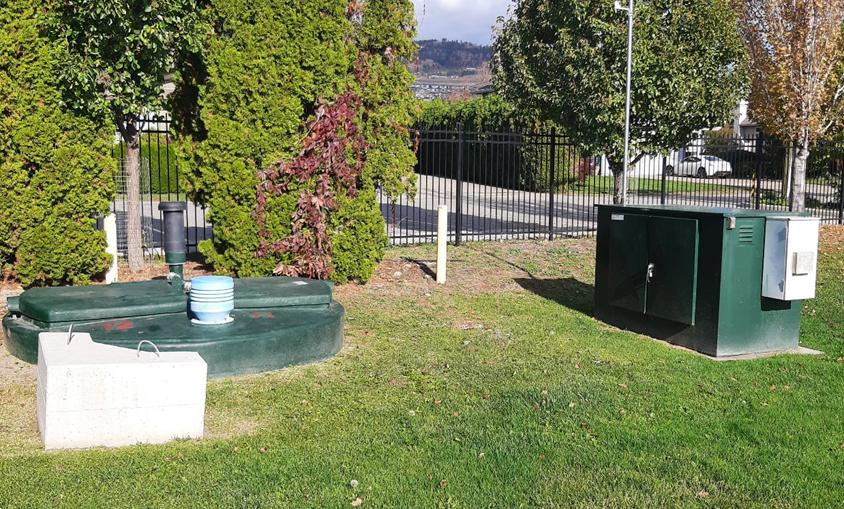
Site Photo:
Service Population: 418 (current) 458 (20 Year Horizon Estimate)
Discharge Manhole: MH ET35 (RDCO)
Last upgrade: Unknown
Other Info:
CONFIGURATION
General Configuration: Below ground wet well and valves with duplex submersible pumps
Wet Well Material: FRP
Wet Well Diameter (m): 2.4
Wet Well Height (m): 6.1
Wet Well Condition: Unknown
Inlet Pipe Material PVC
Inlet Pipe Size (mm): 200
Components:
VFDs: No
Check Valve: Yes (100mm HDL Ball Check Valve)
Isolation Valve: Yes (100mm Dezurik Plug Valve)
Access Hatches: Yes (Aluminum)
Emergency Response Items:
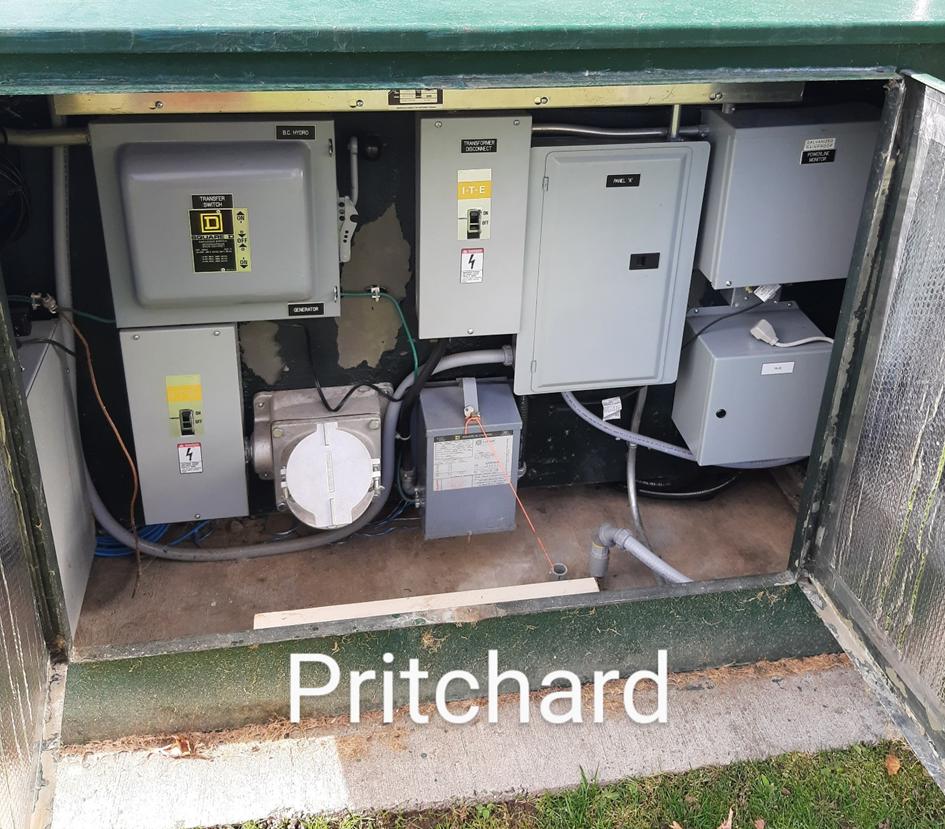
Standby Generator: No
Pump Bypass Connections: No
Portable Generator Connection: Yes (600V)
Emergency Suction: No Critical Spare Pump: Yes
Ladder: Yes (Aluminum)
Platform: Yes (FRP)
Odour Control:Yes (on Exhaust Vent Pipe)
Ventilation: Yes (mounted on top of wet well lid)
Wet Well Photo:Piping and Valving Photo:
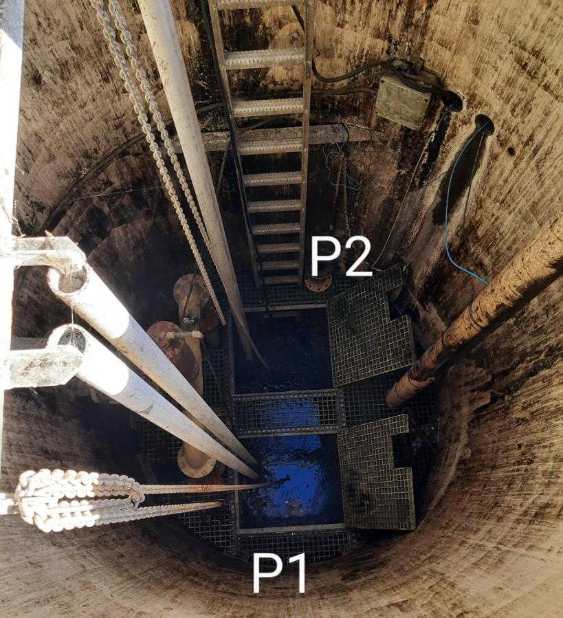
Pump #1Pump #2
600V600V
33
Power: 10 hp10 hp
Rotational Speed (rpm): 1740 rpm1740 rpm
Make: FlygtFlygt
Model No.: CP3127 HTCP3127 HT
Impeller Number: 483483
Serial Number: CP3127.180HTCP3127.180HT
Install Year: 19931993
Rate (L/s): 1515
Head (m):
Flow Records Information (2022-2024 Data) Pump Capacity (Max. Day Flow):
Domestic Flow Rate (DFR) (L/cap/day): 319 Average Day Flow (L/s): 1.54 Maximum Day Flow (L/s) (Existing): 2.61 (Estimated from Modelling) Maximum Day Flow (L/s) (20 Year): 3.33 (Estimated from Modelling)
Bylaw Flow Estimates
Average Dry Weather Flow - Current (L/s): 1.69 at 350 L/cap/day
Average Dry Weather Flow - Future (L/s): 1.86 at 350 L/cap/day
Pump Cycle Time - Current (2022-2024 Data) at Average Day Flow (min): 22.48
per Hour (per Pump)*: 1.3 at Maximum Day Flow (min): 14.44
per Hour (per Pump)*: 2.1 *Bylaw maximum pump starts - 4 times per hour per pump
STATION ELECTRICAL AND CONTROL
Station Supply: 600V
Instrumentation & Controls Phase: 3
Direct Logic 405 D4-450
Transformer Size (kVA): 3 Flow Meter: Yes (Fisher & Porter, non-functioning)
Main Breaker (A): 60
UPS Power Capacity (VA): 1000
Generator
Model: n/a
Power Rating (kW): n/a
Fuel Source: n/a
Level Control: Yes (Vega Pulse C21)
Pressure Transmitter: n/a
Pressure Gauge: n/a
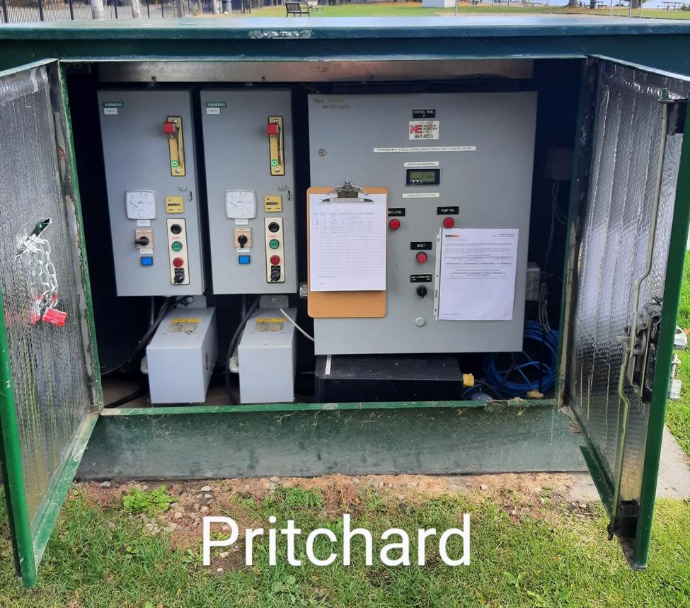
SCADA Integration: Yes
Alarms Functioning: No
Measured Current Pulled by Pump Motor
Proximity to Watercourses:
Description of Nearby Watercourse: Okanagan Lake
Flood of Record Elevation: 343.25m (Okanagan Basin Water Board)
Flood Construction Level: 343.66m (CoWK Bylaw No. 265)
Lift Station Site Elevation: 343.81m
Lift Station Flood Protection Measures: Above Flood Construction Level
Spill Protection Measures: Each pump provides adequate capacity for peak day
1. Lift station located in Marjorie Pritchard Memorial Park near Okanagan Lake. Site is behind park fence and surrounded by vegetation.
2. Valves (plug and check) are located in wet well. Confined space entry required to operate.
3. No primary fall protection at the hatch.
4. Lift station does not have a standby generator. Also no emergency storage as HWL alarm is above inlet pipe.
5. Flow meter is non-functioning (at least since 2010), and lift station has no SCADA alarms or trending. Pumps are pumping equally on SCADA.
6. Lift station aged (31 years old - 1993) with no major renewal. Pumps were rebuilt in 2018. Equipment at end of life, failures have started to occur (check valve ~1.5 years ago). Lift station recently received a Vega transmitter.
7. Forcemain velocity is only 0.85 m/s and does not meet the City bylaw minimum (1.0 m/s)
8. Pump curve shows overall efficiency is approx. 47%.
8. Site access is challenging as lawn around lift station is often saturated from sprinklers and there is no driveway for heavy equipment, such as vac-truck.
9. No recorded odour complaints near lift station or forcemain discharge. Lift station has odour control on exhaust vent.
10. Higher priority for operators due to lift station's proximity to Okanagan Lake. Operator identified as second highest priority for upgrade.
11. Upgrade for Pritchard Lift Station is currently under design.
1. Replace aged process mechanical equipment (pumps, piping, and valves). Valves to be in above ground valve chamber (Barski).
2. Review pump selection at time of renewal to select a pump that is better suited for the system and operates near its BEP to increase pump efficiency.
3. Add flow meter to lift station with process mechanical upgrade. Flow meter to be located in above ground valve chamber.
4. Upgrade aged electrical and controls equipment in conjunction with process mechanical upgrade. Include SCADA alarms.
5. Add standby generator to lift station with electrical equipment upgrades.
6. Complete testing of existing wet well to confirm condition (can be provided by Barski). If found in acceptable condition, wet well can remain.
7. Review additional safety considerations at time of renewal, such as new hatches with safety grates.
8. Existing odour control may need to be upgraded with above ground valve chamber upgrade. To be confirmed at renewal.
9. Install emergency suction line in wet well and bypass connection on forcemain for emergencies.
10. Civil piping can be maintained. Consider isolation of wet well inflows with knife gate valve in wet well or upstream of lift station.
11. Improve site access to lift station for heavier equipment. Hard surface (asphalt or gravel) or subsurface grass reinforcement as lift station is within a public park. Or improve access from parking lot with fence openings / gate and surface improvements for large equiprment.
12. Consider increasing pump flow rate on next upgrade to increase forcemain velocities, so that minimum scouring velocity is met.
(b) Civil (Piping, Surface Works, Manhole)
(c) Structural (Building, Wet Well³, Valve Chamber)
(d) Process Mechanical (Pumps, Process Piping, Valves, Odour Control)
(e) Building Mechanical (HVAC, Blower, Hoists, Plumbing, Emergency Eyewash & Shower) n/a (f) Electrical & Controls (Starts / VFDs / Service, Cables and Wiring, Controls, Instrumentation, Lighting, Standby Generator)
Notes:
1. Estimated costs are a preliminary Class D estimate in 2025 dollars.
2. Replacement value also includes replacement value of above stated recommendations, assuming those have been or will be implemented at the next lift station upgrade / replacement.
3. For purpose of estimating the lift station's full replacement value, the wet well is included in the replacement value, regardless if it will or will not be replaced at the next upgrade / replacement.
Consequence of Failure
Note: The condition assessment findings are based on background information, documentation, photos, and record drawings provided by the City, and discussions with City operators. No site visits were completed to physically assess the condition of the lift stations. As such, the quality of condition assessment findings is dependent on the quality of data provided to McElhanney, and may not fully represent site conditions.
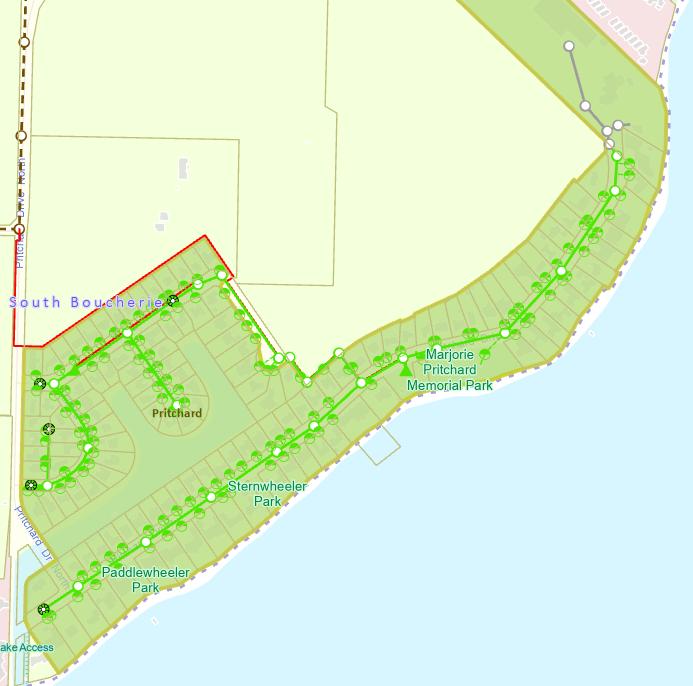
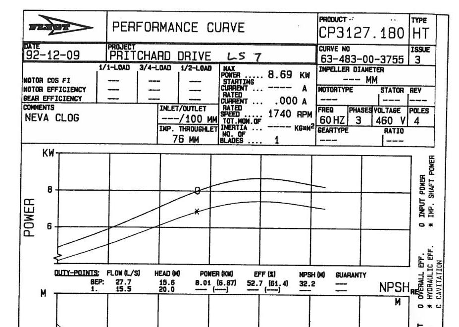


Year Installed: 1992
Municipal Address: 1361 Green Bay Road
Asset Number: LS#2
Catchment Area (ha): 17.8
Service Population: 352 (current)
Site Photo:
387 (20 Year Horizon Estimate)
Discharge Manhole: ET47
Last upgrade: Unknown
Other Info:
Located adjacent to Green Bay Road. Catchment area has no contributing lift stations.
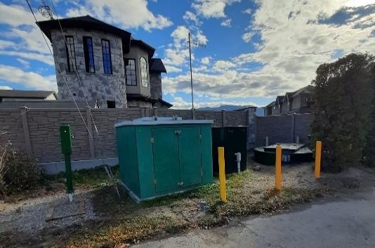
General Configuration: Below ground wet well and valves with duplex submersible pumps
Wet Well Material: FRP
Wet Well Diameter (m): 2.4
Wet Well Height (m): 5.3
Wet Well Condition: Unknown
Inlet Pipe Material PVC
Inlet Pipe Size (mm): 200
Components:
VFDs: Unknown
Check Valve: Yes (150 mm Outside Lever & Weight Check Valve)
Isolation Valve: Yes (150mm Dezurik Plug Valve)
Access Hatches: Yes (Fibreglass)
Emergency Response Items:
Standby Generator: No
Pump Bypass Connections: No
Portable Generator Connection: Yes (600V)
Emergency Suction: No Critical Spare Pump: Yes
Ladder: Yes (Aluminum)
Platform: Yes (Fibreglass)
Odour Control: Yes (On Exhaust Vent Pipe)
Ventilation: Yes (Goose neck only)
Wet Well Photo:Piping and Valving Photo:
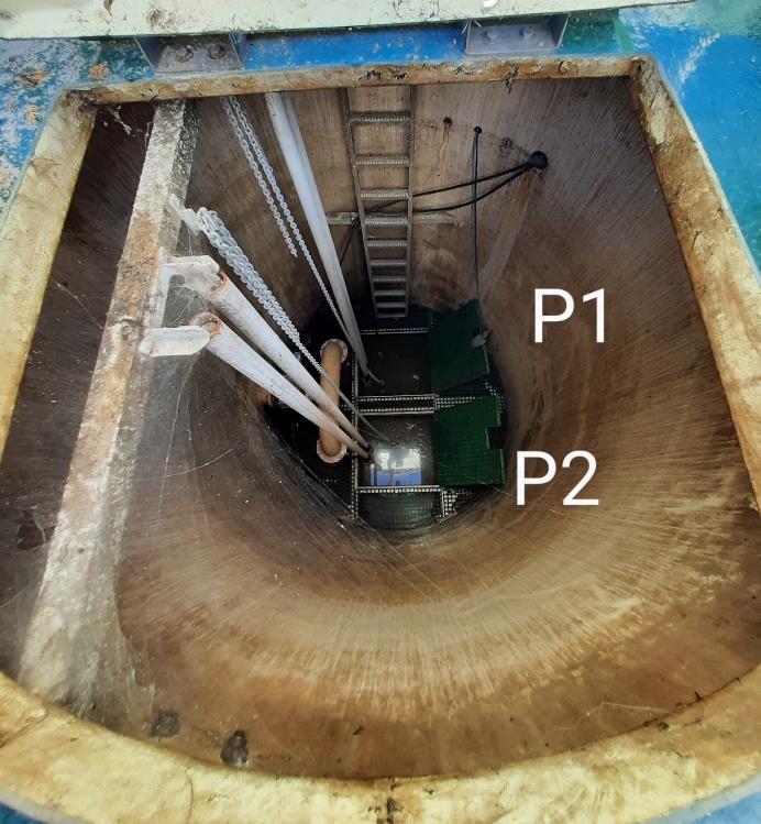
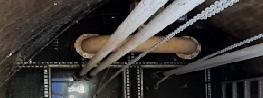
HYDRAULIC STORAGE CAPACITY
Actual Operating Storage (L): Undetermined
Emergency Storage Volume (L)*: Undetermined LeadLagPumps OffHWL AlarmLWL Alarm
Emergency Storage Time - Current (mins)**: Undetermined Setpoints (%) UnknownUnknownUnknown100Unknown
Emergency Storage Time - Future (mins)**: Undetermined Setpoint Depth (m) UndeterminedUndeterminedUndeterminedUndeterminedUndetermined *High Water Alarm to sewer inlet pipe Volume (litres) UndeterminedUndetermined-Undetermined**at Maximum Day Flow
Pump #1Pump #2
600V600V
33
Power: 20 hp20 hp
Rotational Speed (rpm): 17551755
Make: FlygtFlygt
Model No.: CP3152CP3152
Impeller Number: 275275
Serial Number: CP3152.181HTCP3152.181HT
Install Year: 19921992
(L/s): 5050 Design
Head (m): 20.120.1 Design *Bylaw velocities: min. 1 m/s, max. 3.5m/s
Flow Records Information (2022-2024 Data) Pump Capacity (Max. Day Flow):
Domestic Flow Rate (DFR) (L/cap/day): 1222
Average Day Flow (L/s): 4.98
Maximum Day Flow (L/s) (Existing): 3.13 (Estimated from Modelling)
Maximum Day Flow (L/s) (20 Year): 3.35 (Estimated from Modelling)
Bylaw Flow Estimates
Average Dry Weather Flow - Current (L/s): 1.43 at 350 L/cap/day
Average Dry Weather Flow - Future (L/s): 1.57 at 350 L/cap/day
Pump Cycle Time - Current (2022-2024 Data) at Average Day Flow (min): Undetermined
Starts per Hour (per Pump)*: Undetermined at Maximum Day Flow (min): Undetermined Starts per Hour (per Pump)*: Undetermined *Bylaw maximum pump starts - 4 times per hour per pump
Station Supply: 600V
Instrumentation & Controls Phase: 3 PLC: Direct Logic 405 D4-450
Transformer Size (kVA): 5 Flow Meter: Yes (Fisher & Porter, non-functioning)
Main Breaker (A): 100 Level Control: Yes (Vega Pulse C21)
UPS Power Capacity (VA): 1000
Generator
Model: n/a
Power Rating (kW): n/a
Fuel Source: n/a
Pressure Transmitter: Yes (model unknown)
Pressure Gauge: Yes (model unknown)
SCADA Integration: Yes
Alarms Functioning: No
Measured Current Pulled by Pump Motor
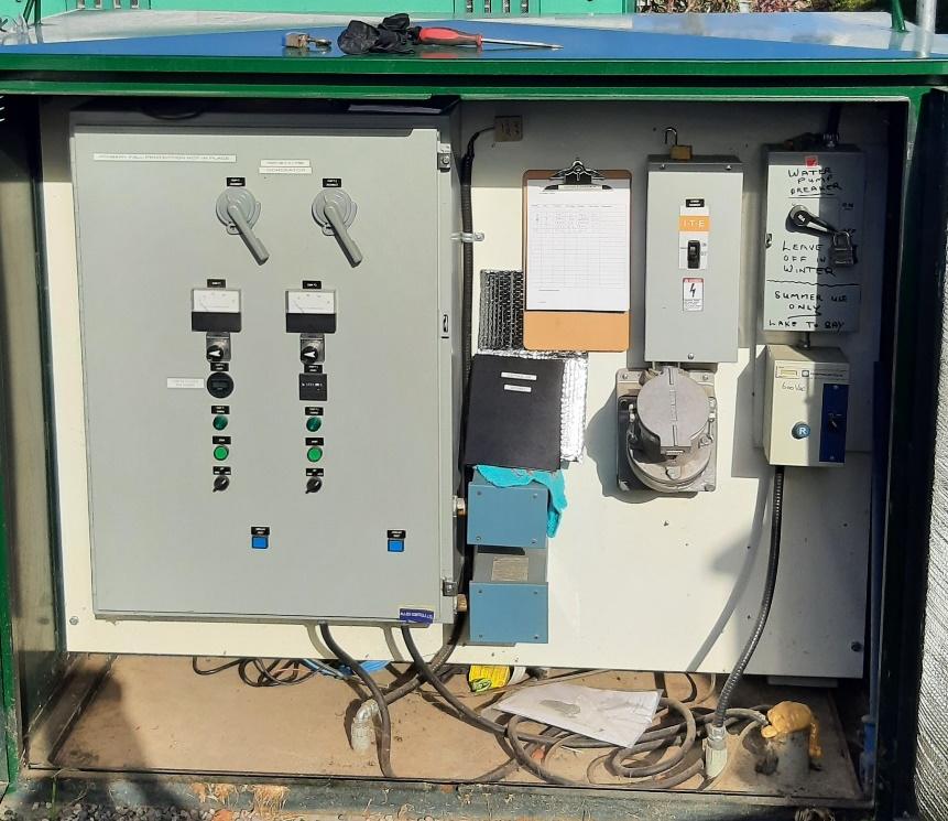
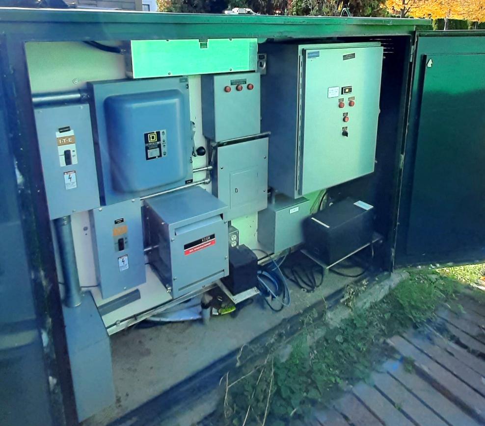
Proximity to Watercourses:
Description of Nearby Watercourse: Okanagan Lake
Flood of Record Elevation: 343.25m (Okanagan Basin Water Board)
Flood Construction Level (FCL): 343.66m (CoWK Bylaw No. 265)
Lift Station Site Elevation: 343.7m
Lift Station Flood Protection Measures: Above Flood Construction Level
Spill Protection Measures: Each pump provides adequate capacity for peak day
1. Lift station located on the shoulder of Green Bay Road, adjacent to Okanagan Lake. Site is protected by bollards and surrounded by vegetation.
2. Valves (plug and check) are located in wet well. Confined space entry required to operate.
3. No primary fall protection at the hatch.
4. Lift station does not have a standby generator.
5. Flow meter is non-functioning (at least since 2010), and lift station has no SCADA alarms or trending.
6. Lift station aged (33 years old - 1992) with no major renewal and equipment is at the end of life. Pumps were rebuilt in 2018. Lift station recently received a Vega transmitter.
7. The calculated domestic flow rate of 1,222 L/cap/day is significant (four times the bylaw value of 350 L/cap/day). Pump flow rate may be incorrect as Average Day Flow is higher than modelled Maximum Day Flow.
8. Setpoints are unknown/not provided and therefore, emergency storage capacity could not be determined.
9. Pump curve shows overall efficiency is approx. 58%, operating very close to the best efficiency point.
10. Site access is good with road access on Green Bay Road.
11. Lift station rim is located 0.04m above flood construction level of Okanagan Lake.
12. Lift station has odour control on exhaust vent and receieves calcium nitrate (BioMaxx) injections.
13. Higher priority for operators due to lift station's proximity to Okanagan Lake. Green Bay identified as third highest priority lift station for upgrade.
14. Upgrade for Green Bay lift station is currently under design.
1. Replace aged process mechanical equipment (pumps, piping, and valves). Valves to be in above ground valve chamber (Barski).
2. Review pump selection at time of renewal to select a pump with improved efficiency.
3. Add flow meter to lift station with process mechanical upgrade. Flow meter to be located in above ground valve chamber.
4. Upgrade aged electrical and controls equipment in conjunction with process mechanical upgrade. Include SCADA alarms.
5. Add standby generator to lift station with electrical equipment upgrades.
6. Complete testing of existing wet well to confirm condition (can be provided by Barski). If found in acceptable condition, wet well can remain.
7. Review additional safety considerations at time of renewal, such as new hatches with safety grates.
8. Existing odour control may need to be upgraded with above ground valve chamber upgrade. To be confirmed at renewal.
9. Install emergency suction line in wet well and bypass connection on forcemain for emergencies.
10. Civil piping can be maintained. Consider isolation of wet well inflows with knife gate valve in wet well or upstream of lift station.
11. Investigate high domestic flow rate. Review data to eliminate potential errors or instrumentation in need of calibration. Complete wet well drawing test to confirm pump flow rate. Also look into potential infiltration from high ground water.
(a)
(b) Civil (Piping, Surface Works, Manhole)
(c) Structural (Building, Wet Well³, Valve Chamber)
(d) Process Mechanical (Pumps, Process Piping, Valves, Odour Control)
(e) Building Mechanical (HVAC, Blower, Hoists, Plumbing, Emergency Eyewash & Shower) n/a (f) Electrical & Controls (Starts / VFDs / Service, Cables and Wiring, Controls, Instrumentation, Lighting, Standby Generator)
Notes:
1. Estimated costs are a preliminary Class D estimate in 2025 dollars.
2. Replacement value also includes replacement value of above stated recommendations, assuming those have been or will be implemented at the next lift station upgrade / replacement.
3. For purpose of estimating the lift station's full replacement value, the wet well is included in the replacement value, regardless if it will or will not be replaced at the next upgrade / replacement.
Note:
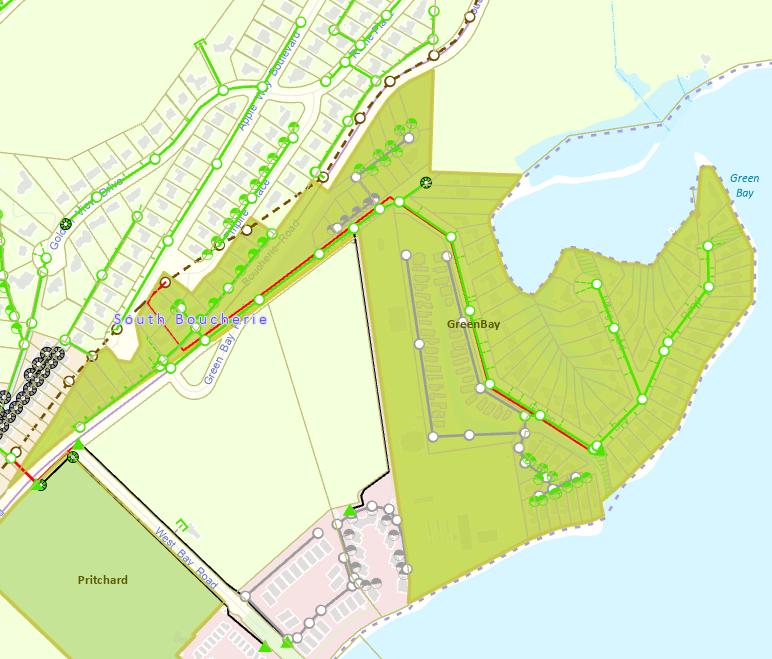
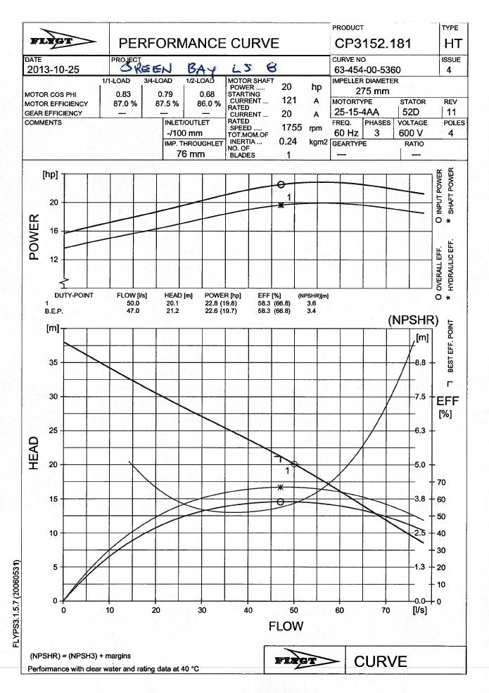

Year Installed: 1997
Municipal Address: 1500 Westgate Road
Asset Number: LS#3
Catchment Area (ha): 3.3
Service Population: 74 (2015) 88 (20 Year Horizon Estimate)
Discharge Manhole: 3EBT6
Last upgrade: n/a
Other Info:
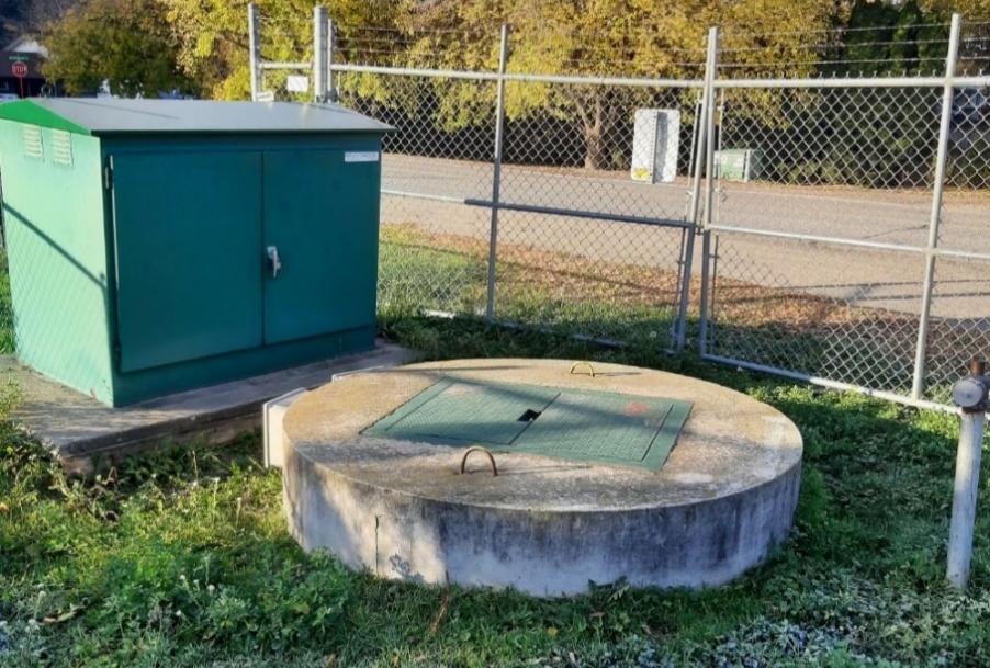
General Configuration: Below ground wet well and valves with duplex submersible pumps
Components:
VFDs: No
Check Valve: Yes (75mm HDL Ball Check Valve)
Isolation Valve: Yes (75mm Plug Valve)
Ladder: No
Platform: No
Odour Control: No
Access Hatches: Yes (Aluminum Checker Plate) Ventilation: No Wet Well Photo:Piping and Valving Photo:
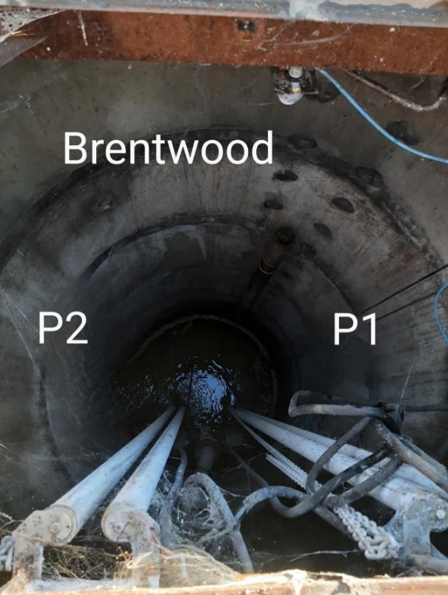
Pump #1Pump #2 Pump Discharge Material:
Voltage: 230V230V
11
Power: 3.9 hp3.9 hp
Rotational Speed (rpm): 17301730
Make: FlygtFlygt
Model No.: CP3102-MTCP3102-MT
Impeller Number: UnknownUnknown
Serial Number: 3102.180.618540158
Install Year: 19971997
(L/s):
Discharge Size (mm):
(m): 10.110.1 Design *Bylaw
Flow Records Information (2022-2024 Data)
Domestic Flow Rate (DFR) (L/cap/day): Undetermined
Average Day Flow (L/s): Undetermined
Pump Capacity (Max. Day Flow):
Maximum Day Flow (L/s) (Existing): 0.67 (Estimated from Modelling)
Maximum Day Flow (L/s) (20 Year): 0.74 (Estimated from Modelling)
Bylaw Flow Estimates
Average Dry Weather Flow - Current (L/s): 0.30 at 350 L/cap/day
Average Dry Weather Flow - Future (L/s): 0.36 at 350 L/cap/day
Pump Cycle Time - Current (2022-2024 Data)
at Average Day Flow (min): Undetermined Starts per Hour (per Pump)*: Undetermined at Maximum Day Flow (min): 37.08 Starts per Hour (per Pump)*: 0.8
*Bylaw maximum pump starts - 4 times per hour per pump
Station Supply: 230V Instrumentation & Controls
Transformer Size (kVA): Unknown Flow Meter: Non-functioning
Main Breaker (A): 100 Level Control: Yes (Bulbs Militronics)
UPS Power Capacity (VA): 1000
Generator
Pressure Transmitter: Yes (model unknown)
Pressure Gauge: No
SCADA Integration: Yes
Model: n/a Alarms Functioning: Yes
Power Rating (kW): n/a
Fuel Source: n/a
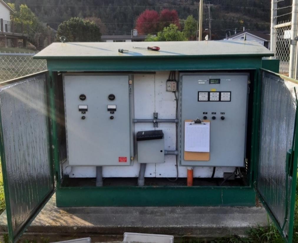
Measured Current Pulled by Pump Motor
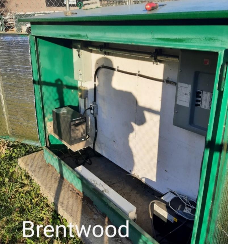
Proximity to Watercourses:
Description of Nearby Watercourse: None Flood of Record Elevation: n/a
Flood Construction Level (FCL): n/a
Lift Station Site Elevation:
Lift Station Flood Protection Measures: n/a
Spill Protection Measures: Each pump provides adequate capacity for peak day
1. Lift station located off of the gravel shoulder on Westgate Road. Site is fenced in a commercial area with good access.
2. Valves (plug and check) are located in concrete wet well. Confined space entry required to operate.
3. No primary fall protection at the hatch.
4. Lift station does not have a standby generator or transfer switch. There is no emergency storage as HWL alarm is above inlet pipe.
5. Flow meter has failed. Recent flow data (pump run times) were not provided so remaining pump capacity cannot be determined.
6. Lift station is aging (28 years old - 1997) with no major renewal. Equipment at end of life, operators noted capacitors (starters) can be an issue. Lift station recently received a Vega transmitter.
7. Lift station has no odour control.
8. Pump curve shows overall efficiency is approx. 36%, operating far from its' best efficiency point.
9. Operators would like above ground valving and a new flow meter. Noted concrete wet well will need to be addressed.
10. Lift station has no critical spare pump.
1. Replace aged process mechanical equipment (pumps, piping, and valves). Valves to be in above ground valve kiosk adjacent to wet well.
2. Review pump selection at time of renewal to select a pump that is better suited for the system and operates near its BEP to increase pump efficiency.
3. Add flow meter to lift station with process mechanical upgrade. Flow meter to be located in above ground valve chamber.
4. Upgrade aged electrical and controls equipment in conjunction with process mechanical upgrade. Include SCADA alarms.
5. Review need for standby generator and add if needed. Consider installing a transfer switch.
6. Review condition of existing concrete wet well to confirm condition. If found in unacceptable condition, replace, or an FRP slip lining upgrade could be installed if feasible.
7. Review additional safety considerations at time of renewal, such as new hatches with safety grates.
8. Complete odour control review at time of renewal.
9. Install emergency suction line in wet well and bypass connection on forcemain for emergencies.
10. Civil piping can be maintained. Consider isolation of wet well inflows with knife gate valve in wet well or upstream of lift station.
11. Procure critical spare pump when pumps are replaced.
Asset Type
(a) General Requirements
(b) Civil (Piping, Surface Works, Manhole)
(c) Structural (Building, Wet Well³, Valve Chamber)
(d) Process Mechanical (Pumps, Process Piping, Valves, Odour Control)
(e) Building Mechanical (HVAC, Blower, Hoists, Plumbing, Emergency Eyewash & Shower) n/a (f) Electrical & Controls (Starts / VFDs / Service, Cables and Wiring, Controls, Instrumentation, Lighting, Standby Generator)
Notes:
1. Estimated costs are a preliminary Class D estimate in 2025 dollars.
2. Replacement value also includes replacement value of above stated recommendations, assuming those have been or will be implemented at the next lift station upgrade / replacement.
3. For purpose of estimating the lift station's full replacement value, the wet well is included in the replacement value, regardless if it will or will not be replaced at the next upgrade / replacement.
4. Standby generator not included in replacement cost.
Note:
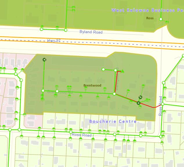
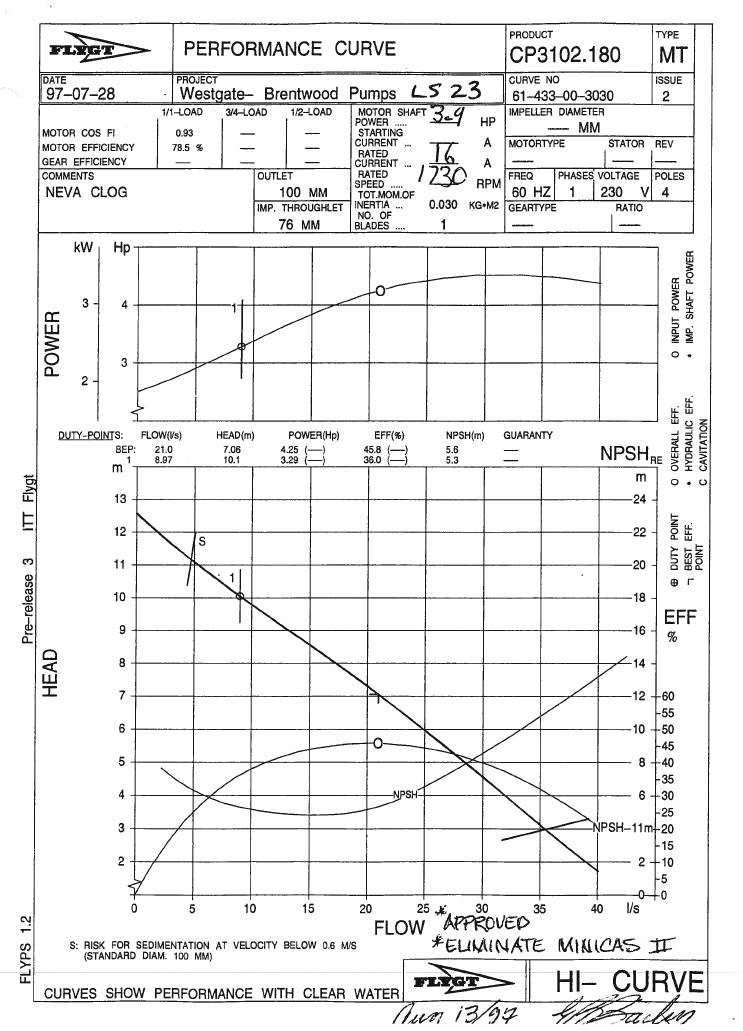

Year Installed: 2001
Municipal Address: 1021 Sunnyside Road
Asset Number: LS#4
Catchment Area (ha): 29.9
IDENTIFICATION
Service Population: 427 (current) 469 (20 Year Horizon Estimate)
Discharge Manhole: LVT11
Last upgrade: 2024
Other Info:
Located adjacent to Sunnyside Road. Contributing lift station is Sunnybrae Lift Station Total catchment area with contributing catchments = 32.1 ha.
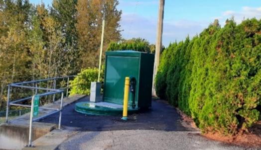
CONFIGURATION
General Configuration: Wet well with above ground valves and duplex submersible pumps
Wet Well Material: FRP
Wet Well Diameter (m): 2.4
Emergency Response Items:
Wet Well Height (m): 4.5 Standby Generator: Yes
Wet Well Condition: Unknown
Pump Bypass Connections: No
Inlet Pipe Material HDPE Portable Generator Connection: No
Inlet Pipe Size (mm): 200 Emergency Suction: Yes Critical Spare Pump: Yes
Components:
VFDs: No (Soft Start)
Check Valve: Yes (100mm HDL Ball Check Valve)
Isolation Valve: Yes (100mm Valmatic Plug Valve)
Access Hatches: Yes (Aluminum/Steel)
Ladder: No
Platform: No
Odour Control: Yes (Sweetvent)
Ventilation: Yes (Gooseneck)
Wet Well Photo:Piping and Valving Photo:
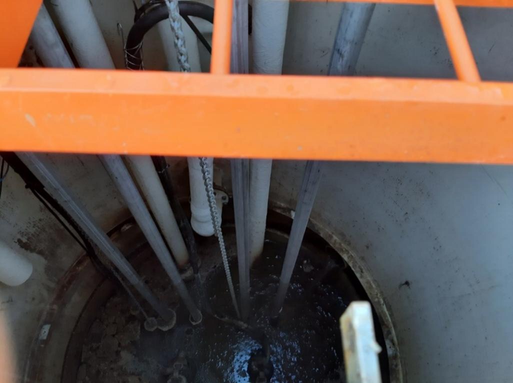
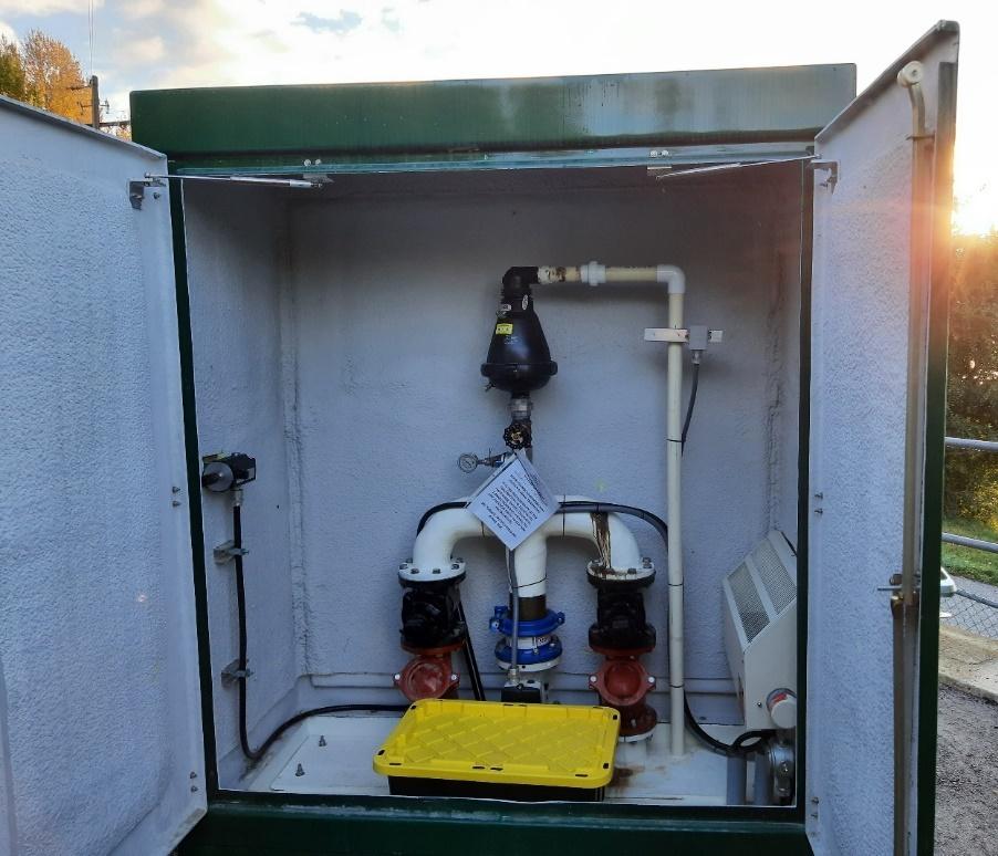
Pump #1Pump #2
575V575V
33
Power: 40 hp40 hp
Rotational Speed (rpm): 34503450
Make: MyersMyers
Model No.: 4RCX400Ms-534RCX400Ms-53
Impeller Number: 26605C51626605C516
Install Year: 20242024
Flow Rate (L/s): 1818 Design
Dynamic Head (m): 6262
Flow Records Information (2022-2024 Data) Pump Capacity (Max. Day Flow): Domestic Flow Rate (DFR) (L/cap/day): 65 Average Day Flow (L/s): 0.32 Maximum Day Flow (L/s) (Existing): 4.08 (Estimated from Modelling) Maximum Day Flow (L/s) (20 Year): 4.32 (Estimated from Modelling)
Bylaw Flow Estimates
Average Dry Weather Flow - Current (L/s): 1.73 at 350 L/cap/day
Average Dry Weather Flow - Future (L/s): 1.90 at 350 L/cap/day
Pump Cycle Time - Current (2022-2024 Data) at Average Day Flow (min): 237.61 Starts per Hour (per Pump)*:
at Maximum Day Flow (min): 23.90 Starts per Hour (per Pump)*:
*Bylaw maximum pump starts - 4 times per hour per pump
Station Supply: 575V Instrumentation & Controls
Logic 205 D2-06B-1 Transformer Size (kVA): 10
Meter: Yes (Siemens) Main Breaker (A): 125
Control: Yes UPS Power Capacity (VA): 1000 Pressure Transmitter: No
Pressure Gauge: Yes (Winters) Generator
SCADA Integration: Yes
Model: SD0150LG176.7D18HPLY3 Alarms Functioning: Yes
Power Rating (kW): 150
Fuel Source: Diesel
Measured Current Pulled by Pump Motor
Kiosk - Electrical and Controls Photo:Control Panel:
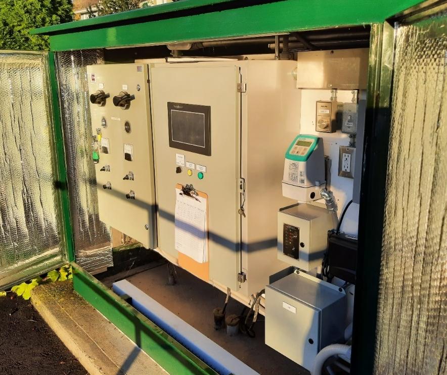
Note: Measured current from Sunnyside Lift Station Commissioning Checklist by Align Engineering (Oct. 11, 2023)
Proximity to Watercourses:
Description of Nearby Watercourse: Bowen Creek
Flood of Record Elevation: Unknown
Flood Construction Level (FCL): Unknown
Lift Station Site Elevation: 365.15m
Lift Station Flood Protection Measures: Unknown if lift station is above flood construction level.
Spill Protection Measures: Each pump provides adequate capacity for peak day
1. Lift station is located off of Sunnyside Road, adjacent to a private park on Okanagan Lake. Site is located between a lockblock retaining wall and a row of vegetation.
2. Lift station is located approx. 27m from Bowen Creek. Creek flood elevations are unknown, but City GIS shows the lift station and creek within 2m elevation difference.
3. One other lift station (Sunnybrae) contributes to this catchment. Failure of this lift station would impact a larger area.
4. Lift station underwent a major upgrade in 2024 to replace process mechanical equipment (incl. new pumps, piping and valves). Valves (plug and check) are now located in an above ground kiosk.
5. Existing FRP wet well (24 years old - 2001) was not replaced during recent upgrade.
6. A standby generator was installed in 2025.
7. Lift station has 223L of emergency storage (approx. 1 minutes) at maximum day flow. Inadequate for response.
9. Lift station has odour control on exhaust vent.
1. Review flood risk of lift station due to potential high flows from Bowen Creek. Review emergency procedures for high creek levels and ensure there is a plan to prevent flooding of the lift station (i.e. sandbagging, tiger dam, etc.) if at risk.
Asset Type
(a) General Requirements
(b) Civil (Piping, Surface Works, Manhole)
(c) Structural (Building, Wet Well³, Valve Chamber)
(d) Process Mechanical (Pumps, Process Piping, Valves, Odour Control)
(e) Building Mechanical (HVAC, Blower, Hoists, Plumbing, Emergency Eyewash & Shower) n/a (f) Electrical & Controls (Starts / VFDs / Service, Cables and Wiring, Controls, Instrumentation, Lighting, Standby Generator)
Notes:
1. Estimated costs are a preliminary Class D estimate in 2025 dollars.
2. Replacement value also includes replacement value of above stated recommendations, assuming those have been or will be implemented at the next lift station upgrade / replacement.
3. For purpose of estimating the lift station's full replacement value, the wet well is included in the replacement value, regardless if it will or will not be replaced at the next upgrade / replacement.
Note:
The condition assessment findings are based on background information, documentation, photos, and record drawings provided by the City, and discussions with City operators. No site visits were completed to physically assess the condition of the lift stations. As such, the quality of condition assessment findings is dependent on
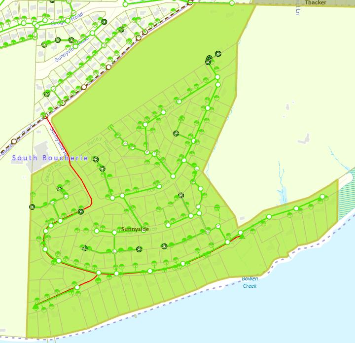
2001 IFT DRAWING (SEE 2024 UPGRADE)
Note: Original 2001 record drawing not provided. Issued for Tender drawing shown below (may not match with installed).
RECORD DRAWING - 2024 UPGRADE









Year Installed: 1990
Municipal Address: 2100 Old Okanagan Hwy
Asset Number: LS#5
Catchment Area (ha): 11.9
Service Population: 396 (current) 406 (20 Year Horizon Estimate)
Discharge Manhole: WB18
Last upgrade: 2015
Other Info:
Located on private property off Old Okanagan Highway. Catchment area has no contributing lift stations.
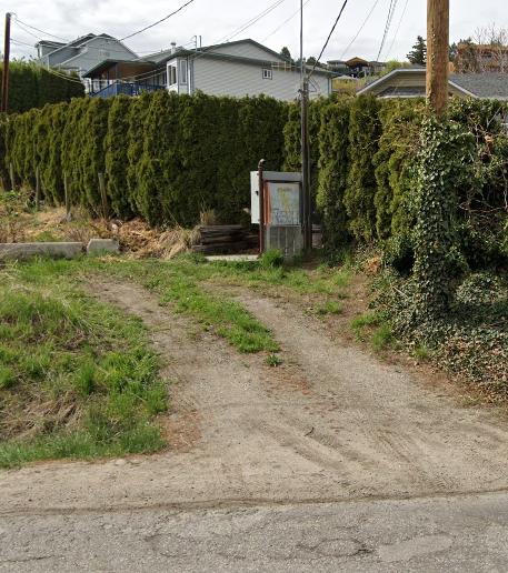
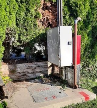
CONFIGURATION
General Configuration: Below ground wet well and valves with duplex submersible pumps
Wet Well Material: Concrete
Wet Well Diameter (m): Unknown
Emergency Response Items:
Wet Well Height (m): Unknown Standby Generator: No
Wet Well Condition: Unknown Pump Bypass Connections: No
Inlet Pipe Material Unknown Portable Generator Connection: Yes (600V)
Inlet Pipe Size (mm): Unknown
Components:
VFDs: No
Check Valve: No
Isolation Valve: No
Access Hatches: Yes (Aluminum)
Emergency Suction: No Critical Spare Pump: Yes
Ladder: Yes
Platform: No
Odour Control: No
Ventilation: Yes
Wet Well Photo (View from P1 Hatch):Wet Well Photo (View from P2 Hatch):
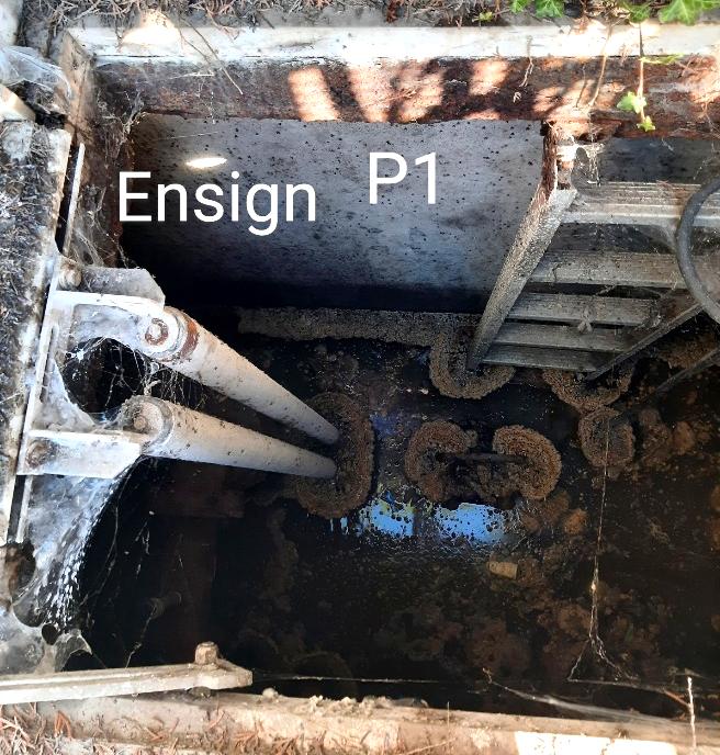
Actual Operating Storage (L): Undetermined
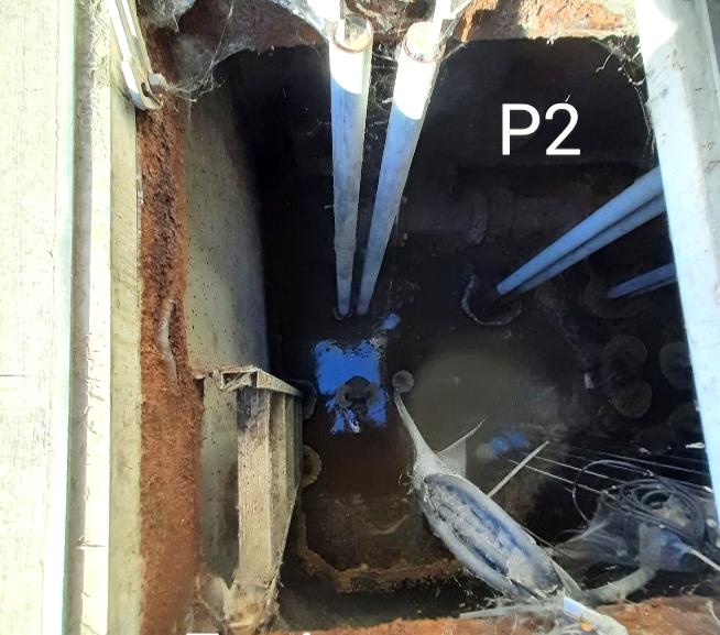
HYDRAULIC STORAGE CAPACITY
Emergency Storage Volume (L)*: Undetermined LeadLagPumps OffHWL AlarmLWL Alarm
Emergency Storage Time - Current (mins)**: Undetermined Setpoints (%) 404515/169010
Emergency Storage Time - Future (mins)**: Undetermined Setpoint Depth (m) UndeterminedUndeterminedUndeterminedUndeterminedUndetermined
*High Water Alarm to sewer inlet pipe Volume (litres) UndeterminedUndetermined-Undetermined**at Maximum Day Flow
#1Pump #2
600V600V
33
Power: 20 hp20 hp
Rotational Speed (rpm): 35203520
Make: FlygtFlygt
Model No.: 31523152
Impeller Number: 320320
Serial Number: 3152.181-88601163152.181-8860117
Head (m):
Flow Records Information (2022-2024 Data) Pump Capacity (Max. Day Flow):
Domestic Flow Rate (DFR) (L/cap/day): 265
Average Day Flow (L/s): 1.22
Maximum Day Flow (L/s) (Existing): 3.07 (Estimated from Modelling) Maximum Day Flow (L/s) (20 Year): 3.07 (Estimated from Modelling)
Bylaw Flow Estimates
Average Dry Weather Flow - Current (L/s): 1.60 at 350 L/cap/day
Average Dry Weather Flow - Future (L/s): 1.64 at 350 L/cap/day
Pump Cycle Time - Current (2022-2024 Data) at Average Day Flow (min): Undetermined Starts per Hour (per Pump)*: Undetermined at Maximum Day Flow (min): Undetermined Starts per Hour (per Pump)*: Undetermined
*Bylaw maximum pump starts - 4 times per hour per pump
Station Supply: 600V
ELECTRICAL AND CONTROL
Instrumentation & Controls
Phase: 3 PLC: Direct Logic 06 D0-06DD1-D
Transformer Size (kVA): Unknown
Main Breaker (A): 100
UPS Power Capacity (VA): 1000
Generator
Model: n/a
Power Rating (kW): n/a
Fuel Source: n/a
Flow Meter: No
Level Control: Yes (Model Unknown)
Pressure Transmitter: No
Pressure Gauge: No
SCADA Integration: Yes
Alarms Functioning: Yes
Measured Current Pulled by Pump Motor
No.1No.2
17.6A20.1A Left leg (T1)
17.8A20.5A Middle leg (T2)
17.9A19.8A Right leg (T3)
Kiosk - Electrical Side Photo:Kiosk - Control Side Photo:
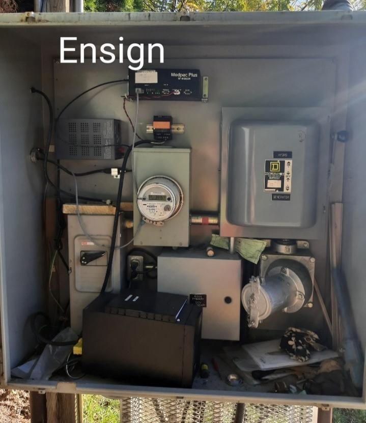
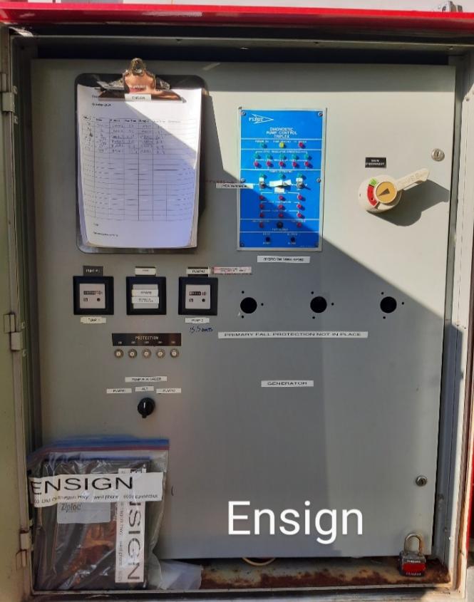
Proximity to Watercourses:
Description of Nearby Watercourse: None
Flood of Record Elevation: n/a
Flood Construction Level (FCL): n/a
Lift Station Site Elevation: ~453 m
Lift Station Flood Protection Measures: n/a
Spill Protection Measures: Each pump provides adequate capacity for peak day
1. Record drawings and setpoint depths were not provided for this lift station and as such, assessment of items such as emergency storage volumes could not be determined.
2. Lift station located on private property on a slope with a short gravel driveway off of Old Okanagan Highway. Operators noted that the LS is adjacent to the Westbank First Nation IR9 property line and there is an opportunity to connect to the IR9 gravity system to eliminate this lift station. Existing latecomers agreement set to expire.
3. City staff noted there are no check or isolation valves for this lift station.
4. Lift station does not have a standby generator or flow meter.
5. Lift station is one of the oldest in the City (35 years old - 1990). Staff noted an upgrade in 2015 but did not provide any details of the renewal. Equipment is at its end of life. Pumps were rebuilt in 2018. Photos show a new kiosk installed in 2024 but the extend of the upgrade is unknown.
6. Site access is challenging and operators have noted it is near impossible to service.
7. Lift station has no odour control.
1. A more thorough lift station assessment is recommended as records and data are incomplete or not available.
2. Investigate the feasibility of eliminating this lift station by tying into Westbank First Nation IR#9 gravity system.
3. If eliminating this lift station is not feasible, a full replacement of the lift station is recommended, relocating the works into the public right-of-way or obtaining an SRW with better access off of Old Okanagan Highway. Replacement to include a new FRP wet well and above ground valve chamber, including a new flow meter.
4. Upgrade aged electrical and controls equipment in conjunction with wet well replacement. Include SCADA alarms.
5. Add standby generator to lift station with electrical equipment upgrades, including automatic transfer switch.
6. Review additional safety considerations at time of replacement, such as new hatches with safety grates.
7. Add odour control at time of replacement.
8. Install emergency suction line in wet well and bypass connection on forcemain for emergencies.
9. Civil piping will need to be rerouted to the new lift station location. Consider isolation of wet well inflows with knife gate valve in wet well or upstream of lift station.
Asset Type
(a) General Requirements
(b) Civil (Piping, Surface Works, Manhole)
(c) Structural (Building, Wet Well³, Valve Chamber)
(d) Process Mechanical (Pumps, Process Piping, Valves, Odour Control)
(e) Building Mechanical (HVAC, Blower, Hoists, Plumbing, Emergency Eyewash & Shower) n/a (f) Electrical & Controls (Starts / VFDs / Service, Cables and Wiring, Controls, Instrumentation, Lighting, Standby Generator)
3. For purpose of estimating the
2. Replacement value also includes replacement value of above stated recommendations, assuming those have been or will be implemented at the next lift station upgrade / replacement. Probability of Failure
value, regardless if it will or will not be replaced at the next upgrade / replacement.
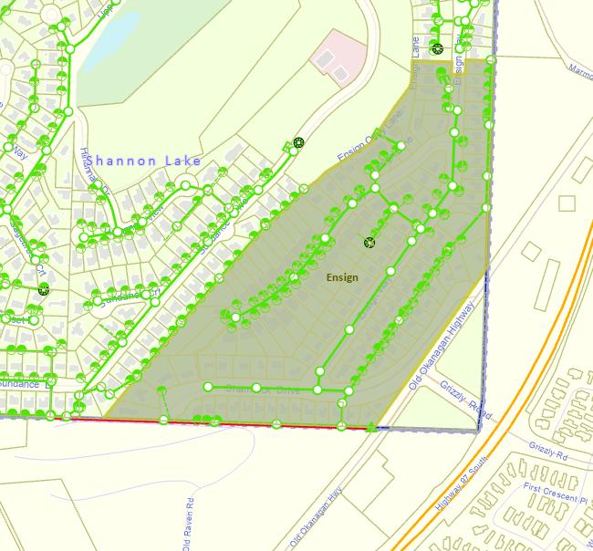
Record drawing not provided.
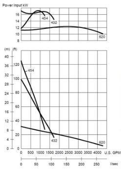
Year Installed: 1997
Municipal Address: 2480 Ross Road
Asset Number: LS#6
Catchment Area (ha): 78.2
Service Population: 366 (current)
IDENTIFICATION
Site Photo:
366 (20 Year Horizon Estimate)
Discharge Manhole: 3EB12
Last upgrade: Unknown
Other Info:
General Configuration:
Located at the corner of Ross Road and Stevens Road in an industrial area. Also known as Westside Industrial Park 2. Catchment area has no contributing lift stations.
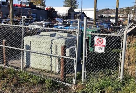
CONFIGURATION
Wet well with above ground duplex self-priming pumps and valves
Wet Well Material: Precast Concrete Box Culvert
Wet Well Diameter (m): 2.4m x 2.4m
Emergency Response Items:
Wet Well Height (m): 4.4 Standby Generator: No
Wet Well Condition: Unknown
Inlet Pipe Material PVC
Inlet Pipe Size (mm): 200
Components:
VFDs: No
Check Valve: Yes (100mm Cast Iron Check Valve)
Isolation Valve: Yes (100mm Cast Iron Plug Valve)
Access Hatches: Yes (Manhole Frame and Covers)
Pump Bypass Connections: No
Portable Generator Connection: Yes (600V)
Emergency Suction: No Critical Spare Pump: Yes
Ladder: Yes
Platform: No
Odour Control: No
Ventilation: Yes
Wet Well Photo:Piping and Valving Photo:
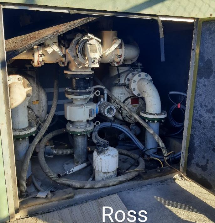
Actual Operating Storage (L): Undetermined
Emergency Storage Volume (L)*: Undetermined
Emergency Storage Time - Current (mins)**: Undetermined Setpoints (%)
Emergency Storage Time - Future (mins)**: Undetermined Setpoint Depth (m)
*High Water Alarm to sewer inlet pipe Volume (litres) UndeterminedUndetermined-Undetermined**at Maximum Day Flow
Pump #1Pump #2
575V575V
33
Power: 20 hp20 hp
Rotational Speed (rpm): 15501550
Make: Gorman RuppGorman Rupp
Model No.: T-4T-4
Impeller Number: 35615-0871095835615-08710958
Serial Number: 17552631755263
Flow Records Information (2022-2024 Data)
Domestic Flow Rate (DFR) (L/cap/day): 258
Average Day Flow (L/s): 1.09
Maximum Day Flow (L/s) (Existing): 9.13 (Estimated from Modelling) Maximum Day Flow (L/s) (20 Year): 15.52 (Estimated from Modelling)
Bylaw Flow Estimates
Average Dry Weather Flow - Current (L/s): 1.48 at 350 L/cap/day
Average Dry Weather Flow - Future (L/s): 1.48 at 350 L/cap/day
Pump Cycle Time - Current (2022-2024 Data) at Average Day Flow (min): Undetermined Starts per Hour (per Pump)*: Undetermined at Maximum Day Flow (min): Undetermined Starts per Hour (per Pump)*: Undetermined *Bylaw maximum pump starts - 4 times per hour per pump
Station Supply: 575V
Phase: 3
Pump Capacity (Max. Day Flow):
STATION ELECTRICAL AND CONTROL
Instrumentation & Controls
Direct Logic 205 D2-04B
Transformer Size (kVA): 5 Flow Meter: No Main Breaker (A): 125 Level Control: No
UPS Power Capacity (VA): 1000
Generator
Model: n/a
Power Rating (kW): n/a
Fuel Source: n/a
Pressure Transmitter: Yes (Militronics)
Pressure Gauge: No
SCADA Integration: Yes
Alarms Functioning: Yes
Measured Current Pulled by Pump Motor
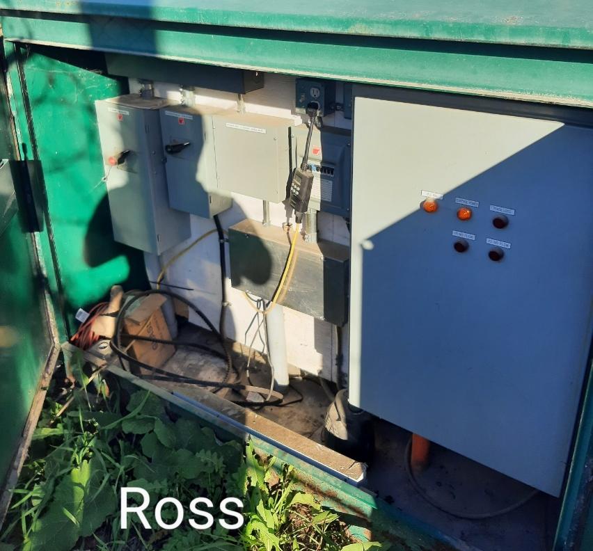
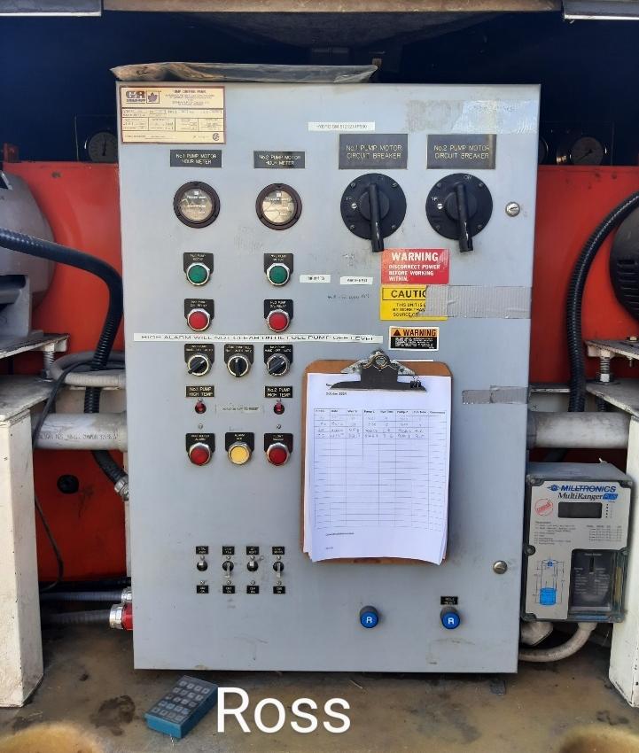
Proximity to Watercourses:
Description of Nearby Watercourse: None
Flood of Record Elevation: n/a
Flood Construction Level (FCL): n/a
Lift Station Site Elevation: 474.56m
Lift Station Flood Protection Measures: n/a
Spill Protection Measures: Each pump provides adequate capacity for peak day
1. Lift station located in an industrial area on the corner of Ross and Industrial Roads. Site is fully fenced.
2. Lift station uses self-priming pumps instead of the typical submersible pumps.
3. Other lift stations contribute to this catchment. Failure of this lift station would impact a much larger area.
4. Pumps and valves (plug and check) are located in a removable FRP enclosure above ground. Wet well is a precast concrete box culvert.
6. Setpoints are unknown/not provided and therefore, emergency storage capacity could not be determined.
7. Lift station aged (28 years old - 1997) with no major renewal. Equipment at end of life.
8. Operators noted site footprint is very small and any upgrades may be challenging without obtaining additional land.
9. No recorded public odour complaints but operators noted this station is the worst for odour when being cleaned out.
10. Operators noted this station is in need of renewal and additional lift stations have been added to the catchment area . Operator identified as fourth highest priority for upgrade.
1. A full replacement of this lift station is recommended, complete with a new FRP wet well and above ground valve chamber, including a new flow meter.
2. Investigate the footprint requirements for a new lift station. Consult with adjacent land owners to discuss opportunity for land purchase.
3. Upgrade aged electrical and controls equipment in conjunction with wet well replacement. Include SCADA alarms.
4. Add standby generator to lift station with electrical equipment upgrades.
5. Review additional safety considerations at time of replacement, such as new hatches with safety grates.
6. Add odour control at time of replacement.
7. Install emergency suction line in wet well and bypass connection on forcemain for emergencies.
8. Civil piping can be maintained. Consider isolation of wet well inflows with knife gate valve in wet well or upstream of lift station.
Asset Type
(a) General Requirements
(b) Civil (Piping, Surface Works, Manhole)
(c) Structural (Building, Wet Well³, Valve Chamber)
(d) Process Mechanical (Pumps, Process Piping, Valves, Odour Control)
(e) Building Mechanical (HVAC, Blower, Hoists, Plumbing, Emergency Eyewash & Shower) n/a (f) Electrical & Controls (Starts / VFDs / Service, Cables and Wiring, Controls, Instrumentation, Lighting, Standby Generator)
Notes:
1. Estimated costs are a preliminary Class D estimate in 2025 dollars.
2. Replacement value also includes replacement value of above stated recommendations, assuming those have been or will be implemented at the next lift station upgrade / replacement.
3. For purpose of estimating the lift station's full replacement value, the wet well is included in the replacement value, regardless if it will or will not be replaced at the next upgrade / replacement.
of Failure
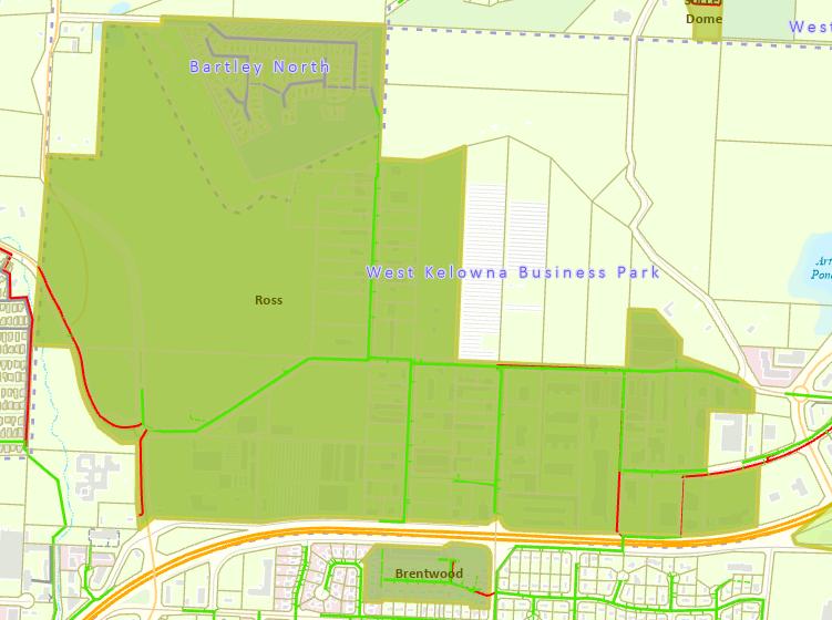
Pump performance curve not provided.
Year Installed: 2006
Municipal Address: 3041 Collens Hill Road
Asset Number: LS#7
Catchment Area (ha): 32.8
Service Population: 400 (current) 647 (20 Year Horizon Estimate)
Discharge Manhole: LV11
Last upgrade: Unknown
Other Info:
Site Photo:
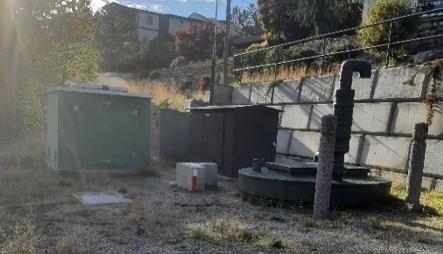
General Configuration: Below ground wet well and valves with duplex submersible pumps
Wet Well Material: FRP
Wet Well Diameter (m): 2.44
Emergency Response Items:
Wet Well Height (m): 6.9 Standby Generator: No
Wet Well Condition: Very good
Inlet Pipe Material PVC
Pump Bypass Connections: No
Portable Generator Connection: Yes (600V)
Inlet Pipe Size (mm): 200 Emergency Suction: Yes (100mm) Critical Spare Pump: Yes
Components:
VFDs: No (Soft Start)
Ladder: Yes
Check Valve: Yes (100mm HDL 5087 Ball Check Valve) Platform: Yes
Isolation Valve: Yes (100mm Cast Iron Plug Valve)
Access Hatches: Yes (Aluminum)
Odour Control: Yes (Carbon Filter)
Ventilation: Yes
Wet Well Photo:Piping and Valving Photo:
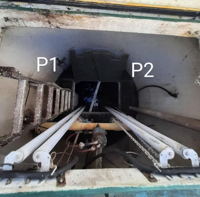
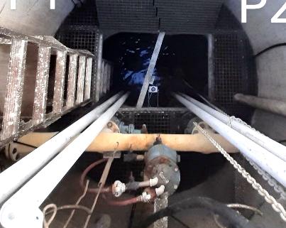
Bylaw
Estimates
Pump Cycle Time - Current (2022-2024 Data) at Average Day Flow (min):
*Bylaw maximum pump starts - 4 times per hour per pump
Station Supply:
(VA):
(kW): n/a Fuel Source: n/a
per
(per
STATION ELECTRICAL AND CONTROL
Proximity to Watercourses:
Description of Nearby Watercourse: None
Flood of Record Elevation: n/a
Flood Construction Level (FCL): n/a
Lift Station Site Elevation: 421.75m
Lift Station Flood Protection Measures: n/a
Spill Protection Measures: Each pump does not provide adequate capacity for peak day
Lift station was assessed on October 15, 2025 as part of another project. Field observations noted here.
1. Lift station down a gravel access road off of Collens Hill Road in a residential neighbourhood. Lift station is adjacent to a retaining wall.
2. Valves (plug and check) are located in wet well. Confined space entry required to operate.
3. Lift station does not have a standby generator. Emergency storage is calculated to be 331L (approx. 1 minute) at maximum day flow. Inadequate for response. 4. Lift station does have a flow meter that is reporting on SCADA. Pump drawdown test completed to determine pumping rates for each pump and cross-check the flow meter. Flow meter showing correctly.
5. Pump #2 has inadequate capacity for future peak flows. Firm capacity requirements not met.
6. Forcemain velocity is only 0.45 m/s based on drawdown test and does not meet the City bylaw minimum (1.0 m/s)
7. Lift station is approx. 19 years old (installed in 2006) with no major renewal. Generally in good condition.
8. Flows are far left on pump curve (near pump shutoff head) and far from best efficiency point. Pump curve may be incorrect. Operators noted that flows were 7 L/s in March 2021 (significant drop in puming rate for 4 years of use).
9. Starts per hour are low. Increased retention time.
10. Site access is good. Site is not fenced but operators have not had any challenges.
11. Lift station has carbon filter odour control on vent. No odour issues noted.
12. Operators noted there has been a lot of population growth / development in this area, increasing flows.
1. Add valves to above ground valve chamber to eliminate confined space entry at next upgrade. Mechanical process equipment (pumps, piping, and valves) generally in good condition, so an immediate upgrade not requied.
2. Upgrade pumps once future peak flows are reached.
3. Upgrade flow meter with next process mechanical upgrade. Flow meter to be located in above ground valve chamber.
4. Upgrade electrical and controls equipment in conjunction with process mechanical upgrade. PLC may require an earlier upgrade as becoming outdated.
5. Add standby generator to lift station with electrical equipment upgrades.
6. Complete testing of existing wet well at next upgrade to confirm condition (can be provided by Barski). Currently in good condition. If no significant deterioration in condition found, wet well can remain.
7. New hatches with safety grates required. Review additional safety considerations at time of renewal.
8. Existing odour control may need to be upgraded with above ground valve chamber upgrade. To be confirmed at renewal.
9. Install bypass connection on forcemain for emergencies.
10. Civil piping can be maintained. Consider isolation of wet well inflows with knife gate valve in wet well or upstream of lift station.
11. Review deterioration of pump flow, could be excessive pump wear or issues with forcemain (wear or plugging). If no issues found, consider increasing pump flow rate on next upgrade to increase forcemain velocities, so that minimum scouring velocity is met.
12. Calibrate level control settings, so percentages are representative of wet well depth.
Asset Type
(a) General Requirements
(b) Civil (Piping, Surface Works, Manhole)
(c) Structural (Building, Wet Well³, Valve Chamber)
(d) Process Mechanical (Pumps, Process Piping, Valves, Odour Control)
(e) Building Mechanical (HVAC, Blower, Hoists, Plumbing, Emergency Eyewash & Shower) n/a (f) Electrical & Controls (Starts / VFDs / Service, Cables and Wiring, Controls, Instrumentation, Lighting, Standby Generator)
Notes:
1. Estimated costs are a preliminary Class D estimate in 2025 dollars.
2. Replacement value also includes replacement value of above stated recommendations, assuming those have been or will be implemented at the next lift station upgrade / replacement.
3. For purpose of estimating the lift station's full replacement value, the wet well is included in the replacement value, regardless if it will or will not be replaced at the next upgrade / replacement.
Note:
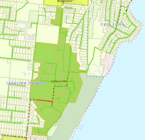
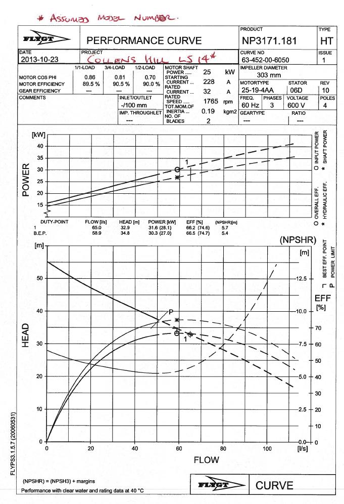

IDENTIFICATION
Year Installed: 2000 Site Photo:
Municipal Address: 2505 Whitworth Road
Asset Number: LS#8
Catchment Area (ha): 9.3
Service Population: 124 (current) 144 (20 Year Horizon Estimate)
Discharge Manhole: 332
Last upgrade: Unknown
Other Info:
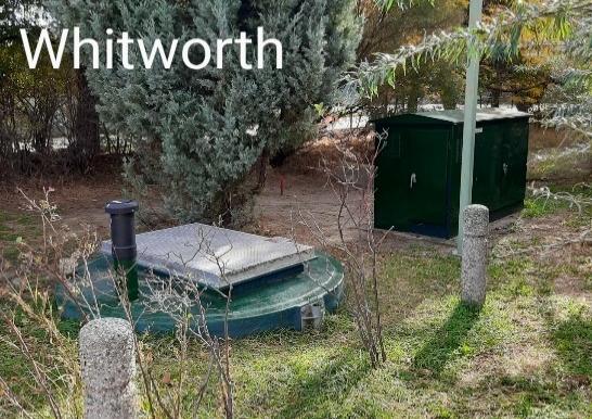
CONFIGURATION
General Configuration: Below ground wet well and valves with duplex submersible pumps
Wet Well Material: FRP
Wet Well Diameter (m): 2.4
Emergency Response Items:
Wet Well Height (m): 6.5 Standby Generator: Yes
Wet Well Condition: Unknown Pump Bypass Connections: No
Inlet Pipe Material PVC Portable Generator Connection: Yes (240V)
Inlet Pipe Size (mm): 200 Emergency Suction: Yes Critical Spare Pump: Yes
Components:
VFDs: No
Check Valve: Yes (75mm HDL Ball Check Valve)
Isolation Valve: Yes (75mm Cast Iron Plug Valve)
Access Hatches: Yes
Ladder: Yes
Platform: Yes (FRP Grating)
Odour Control: No
Ventilation: Yes
Wet Well Photo:Piping and Valving Photo:
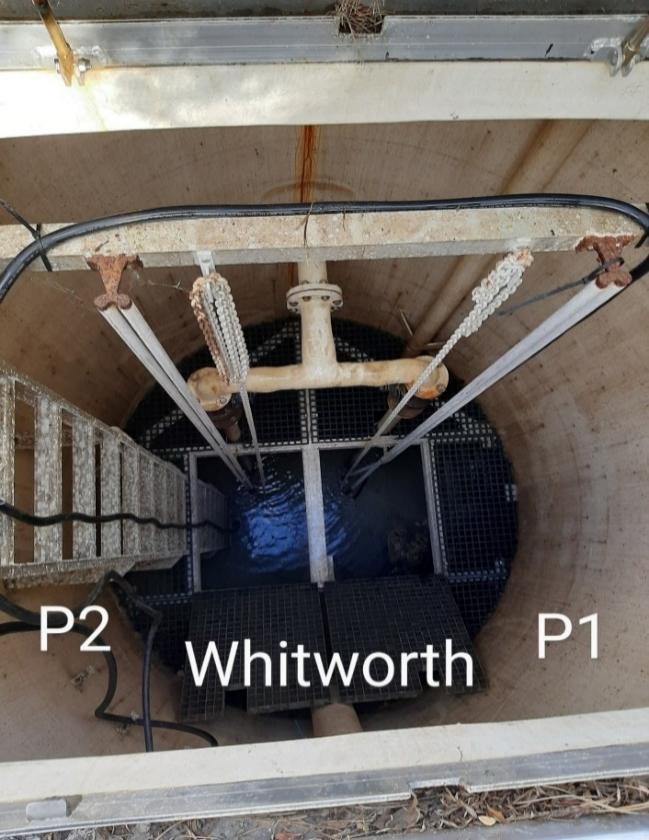
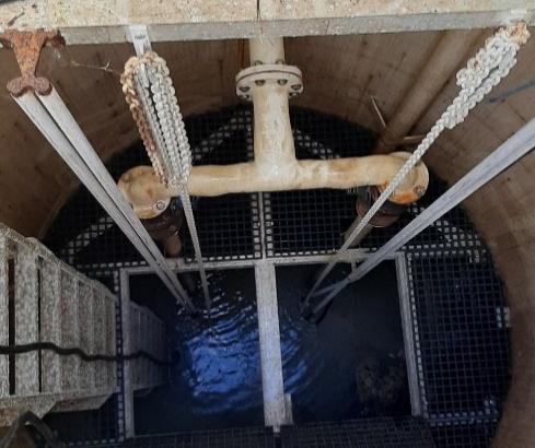
#1Pump #2
230V230V
33
FRP Power: 6 hp6 hp
Rotational Speed (rpm): 34903490
Make: FlygtFlygt
Model No.: MP3102HTMP3102HT
Impeller Number: 155155
Serial Number: MP3102.170MP3102.170
Install Year: 20002000
Flow Rate (L/s): 44 Design
Head (m): 4545
Flow Records Information (2022-2024 Data)
Capacity (Max. Day Flow): Domestic Flow Rate (DFR) (L/cap/day): 108
Average Day Flow (L/s): 0.15 Maximum Day Flow (L/s) (Existing): 1.16 (Estimated from Modelling)
Day Flow (L/s) (20 Year): 1.31 (Estimated from Modelling)
Bylaw Flow Estimates
Average Dry Weather Flow - Current (L/s): 0.50 at 350 L/cap/day
Average Dry Weather Flow - Future (L/s): 0.58 at 350 L/cap/day
Pump Cycle Time - Current (2022-2024 Data) at Average Day Flow (min): 607.78 Starts per Hour (per Pump)*:
*Bylaw maximum pump starts - 4 times per hour per pump
Station Supply: 240V
ELECTRICAL AND CONTROL
Instrumentation & Controls Phase: 3 PLC: Direct Logic 205 D2-06B
Transformer Size (kVA): Unknown Flow Meter: No
Main Breaker (A): 100 Level Control: Yes (Flygt Bulbs Militronics)
UPS Power Capacity (VA): 1000
Generator
Pressure Transmitter: No
Pressure Gauge: No
SCADA Integration: Yes
Model:Alarms Functioning: Yes
Power Rating (kW): 40
Measured Current Pulled by Pump Motor
Fuel Source: Diesel No.1No.2 T1 24.0A20.1A Left leg (T1) T2 7.46A7.8A Middle leg (T2) T3 20.3A16.85A Right leg (T3)
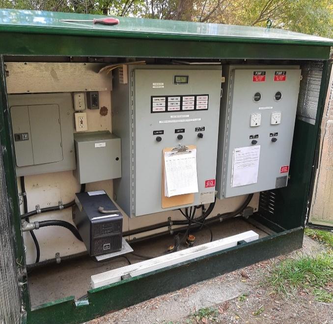
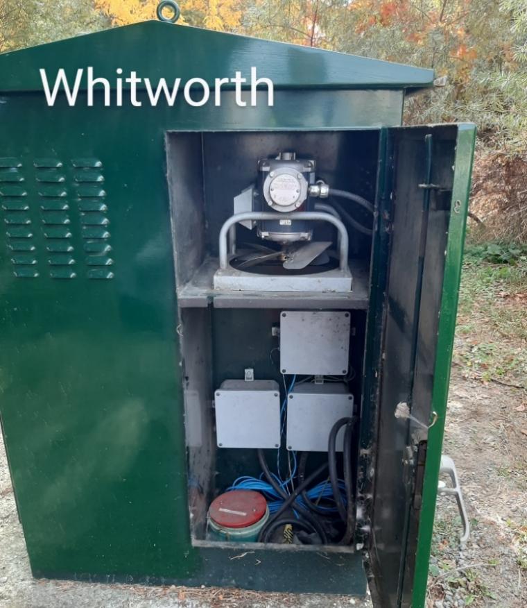
Proximity to Watercourses:
Description of Nearby Watercourse: Okanagan Lake
Flood of Record Elevation: 343.25m (Okanagan Basin Water Board)
Flood Construction Level (FCL):
Lift Station Site Elevation: 343.5m
(CoWK Bylaw No. 265)
Lift Station Flood Protection Measures: Below Flood Construction Level
Spill Protection Measures: Each pump provides adequate capacity for peak day
1. Lift station located at the entrance to Hazelnut Park beach access, just off of Whitworth Road. Site is surrounded by vegetation and bollards.
2. One other lift station (Pebble Beach) contributes to this catchment. Failure of this lift station would impact a larger area.
3. Lift station rim is located 0.16m below the Okanagan Lake flood construction level. At flood risk.
4. Valves (plug and check) are located in wet well. Confined space entry required to operate.
5. A standby generator was installed at this lift station in 2024. There is no emergency storage as HWL alarm is above inlet pipe.
6. Lift station does not have a flow meter.
7. Lift station aged (25 years old - 2000) with no major renewal. Equipment at end of life. Lift station recently received a Vega transmitter.
8. Forcemain velocity is only 0.51 m/s and does not meet the City bylaw minimum (1.0 m/s)
9. Pump curve shows overall efficiency is approx. 30%, operating very close to the best efficiency point.
10. Site access is good with vehicle access and parking on Whitworth Road.
11. Odour complaints have been received in the area (these may be related to the nearby WWTP). Operators are not injecting calcium nitrate (BioMaxx) at Whitworth lift station, but upstream at Pebble Beach lift station.
12. Higher priority for operators due to lift station's proximity to Okanagan Lake. Operators would like to see valves moved into an above ground chamber and a flow meter added.
1. Replace aged process mechanical equipment (pumps, piping, and valves). Valves to be in above ground valve chamber (Barski).
2. Review pump selection at time of renewal to select a pump with improved efficiency.
3. Add flow meter to lift station with process mechanical upgrade. Flow meter to be located in above ground valve chamber.
4. Upgrade aged electrical and controls equipment in conjunction with process mechanical upgrade. Include SCADA alarms.
5. Complete testing of existing wet well to confirm condition (can be provided by Barski). If found in acceptable condition, wet well can remain, but consider raising the wet well with new valve chamber upgrade. If wet well is to be replaced, ensure new wet well elevation is above Okanagan Lake flood construction level.
6. Review additional safety considerations at time of renewal, such as new hatches with safety grates.
7. Add odour control at the time of above ground valve chamber upgrade.
8. Install bypass connection on forcemain for emergencies.
9. Civil piping can be maintained. Consider isolation of wet well inflows with knife gate valve in wet well or upstream of lift station.
10. Review emergency procedures for high lake levels and ensure there is a plan to prevent inflows to the lift station (i.e. sandbagging, tiger dam, etc.).
11. Consider increasing pump flow rate on next upgrade to increase forcemain velocities, so that minimum scouring velocity is met.
(a) General Requirements
(b) Civil (Piping, Surface Works, Manhole)
(c) Structural (Building, Wet Well³, Valve Chamber)
(d) Process Mechanical (Pumps, Process Piping, Valves, Odour Control)
(e) Building Mechanical (HVAC, Blower, Hoists, Plumbing, Emergency Eyewash & Shower)
(f) Electrical & Controls (Starts / VFDs / Service, Cables and Wiring, Controls, Instrumentation, Lighting, Standby Generator)
&
Notes:
1. Estimated costs are a preliminary Class D estimate in 2025 dollars.
2. Replacement value also includes replacement value of above stated recommendations, assuming those have been or will be implemented at the next lift station upgrade / replacement.
3. For purpose of estimating the lift station's full replacement value, the wet well is included in the replacement value, regardless if it will or will not be replaced at the next upgrade / replacement.
Note:
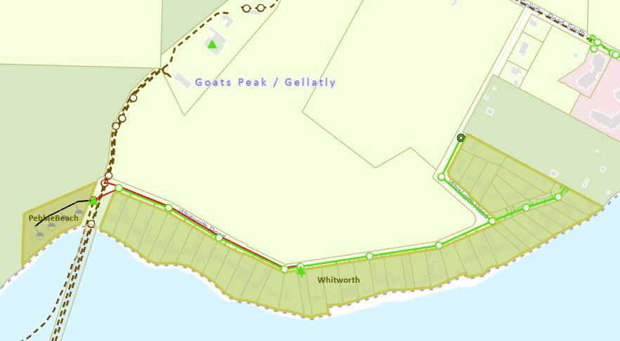
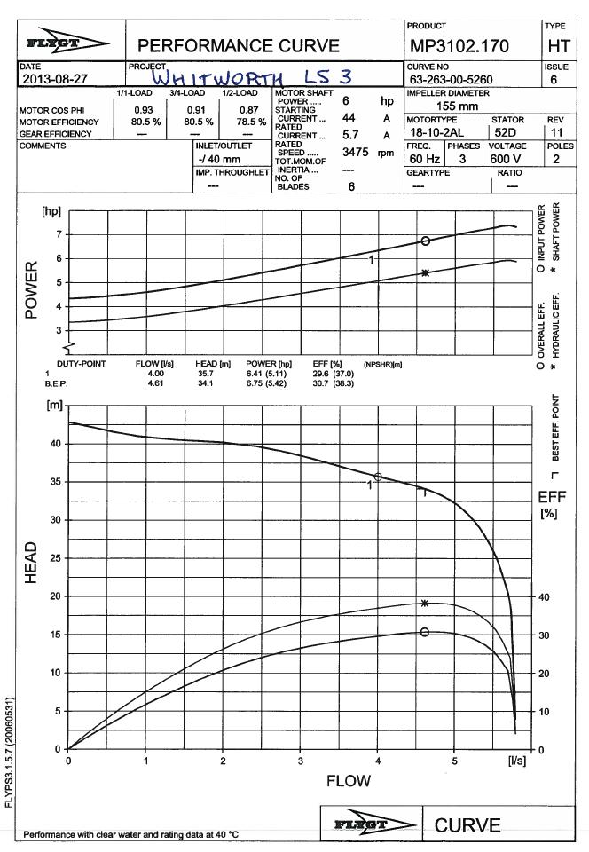
Year Installed: Unknown
Municipal Address: 2200 Westlake Road
Asset Number: LS#9
Catchment Area (ha): Unknown
Site Photo:
Service Population: Unknown (current) Unknown (20 Year Horizon Estimate)
Discharge Manhole: 3EB14
Last upgrade: Unknown
Other Info: Start of the siphon, not a lift station.

General Configuration: Grinder Station
Wet Well Material: Concrete
Wet Well Diameter (m): Unknown
CONFIGURATION
Emergency Response Items:
Wet Well Height (m): Unknown Standby Generator: No
Wet Well Condition: Unknown Pump Bypass Connections: No
Inlet Pipe Material Unknown
Inlet Pipe Size (mm): 100mm & 200mm
Components:
VFDs: No
Check Valve: No
Isolation Valve: No
Access Hatches: Manhole
Portable Generator Connection: Yes (240V)
Emergency Suction: No Critical Spare Pump: N/A
Ladder: Yes
Platform: No
Odour Control: No
Ventilation: No
Inlet Manhole Photo:Grinder Chamber Photo:
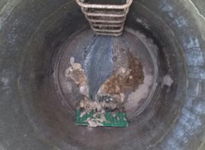
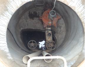
HYDRAULIC STORAGE CAPACITY
Actual Operating Storage (L): Undetermined
Emergency Storage Volume (L)*: Undetermined
Emergency Storage Time - Current (mins)**: Undetermined Setpoints (%)
Emergency Storage Time - Future (mins)**: Undetermined Setpoint Depth (m) UndeterminedUndeterminedUndeterminedUndeterminedUndetermined *High Water Alarm to sewer inlet pipe Volume (litres) UndeterminedUndetermined-Undetermined**at Maximum Day Flow
Pump #1Pump #2
Voltage: 230Vn/a
Phase: 1n/a
Power: Unknownn/a
Rotational Speed (rpm): Unknownn/a
Make: Unknownn/a
Header
Pump Discharge Material: Unknown
Pump Discharge Size (mm): 250
Header Material: n/a
Header Size (mm): n/a
Forcemain (discharges to Siphon)
Model No.: Unknownn/a Material: PVC
Impeller Number: Unknownn/a
Serial Number: Unknownn/a
Install Year: Unknownn/a
Diameter (mm): 250
Length (m): Unknown
Forcemain Velocity (m/s)*: Undetermined
Flow Rate (L/s): Unknownn/a Design Retention Prior to Gravity (mins): Undetermined
Total Dynamic Head (m): Unknownn/a Design *Bylaw velocities: min. 1 m/s, max. 3.5m/s
Flow Records Information (2022-2024 Data)
Domestic Flow Rate (DFR) (L/cap/day): Undetermined
Pump Capacity (Max. Day Flow):
Average Day Flow (L/s): Undetermined
Maximum Day Flow (L/s) (Existing): Undetermined
Maximum Day Flow (L/s) (20 Year): Undetermined
Bylaw Flow Estimates
Average Dry Weather Flow - Current (L/s): Undetermined at 350 L/cap/day
Average Dry Weather Flow - Future (L/s): Undetermined at 350 L/cap/day
Pump Cycle Time - Current (2022-2024 Data) at Average Day Flow (min): Undetermined Starts per Hour (per Pump)*: Undetermined at Maximum Day Flow (min): Undetermined Starts per Hour (per Pump)*: Undetermined *Bylaw maximum pump starts - 4 times per hour per pump
Flow, 0%
Station Supply: 120V
Instrumentation & Controls Phase: 1 PLC: No
Transformer Size (kVA): Unknown Flow Meter: No Main Breaker (A): 100 Level Control: No UPS Power Capacity (VA): 1000
Pressure Transmitter: No
Pressure Gauge: No Generator
Model: n/a
SCADA Integration: No
Alarms Functioning: No
Power Rating (kW): n/a Fuel Source: n/a No.1No.2
Measured Current Pulled by Pump Motor
4.9An/a Left leg (T1)
4.9An/a Middle leg (T2)
n/an/a Right leg (T3)
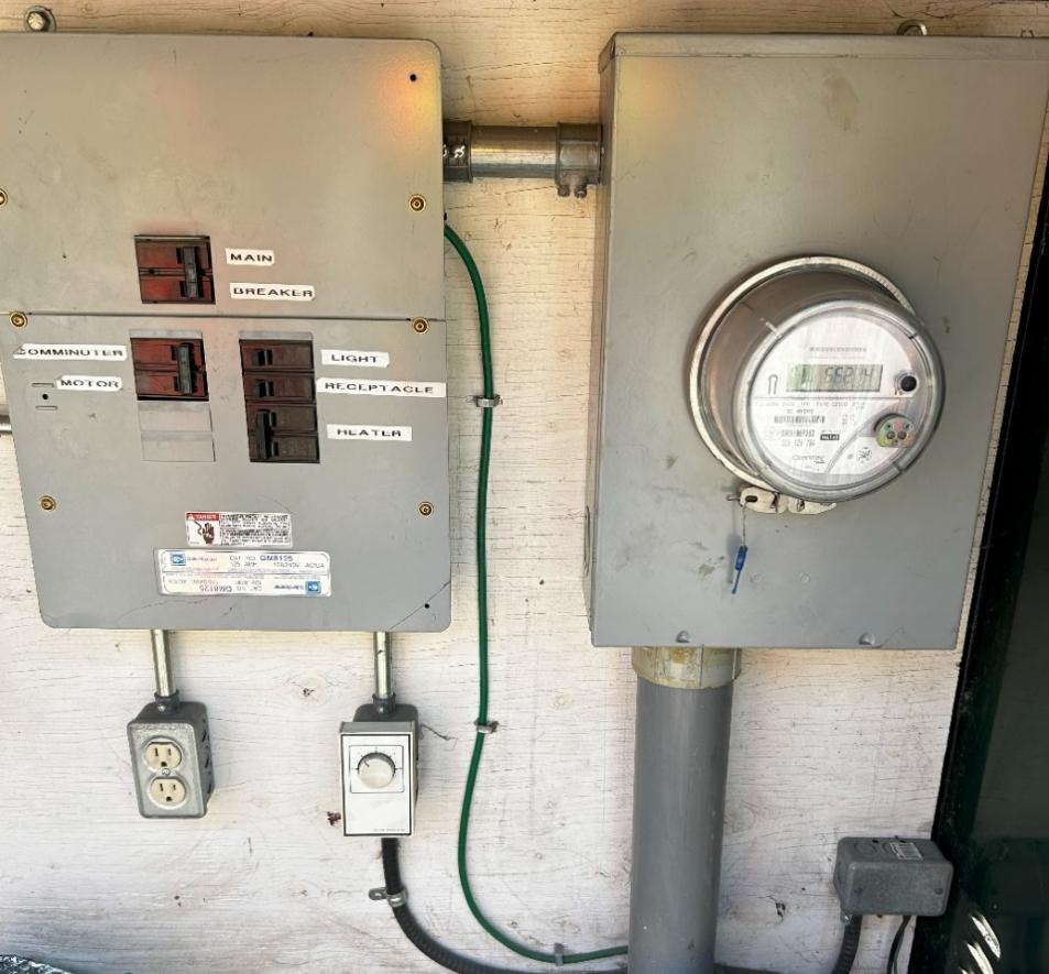
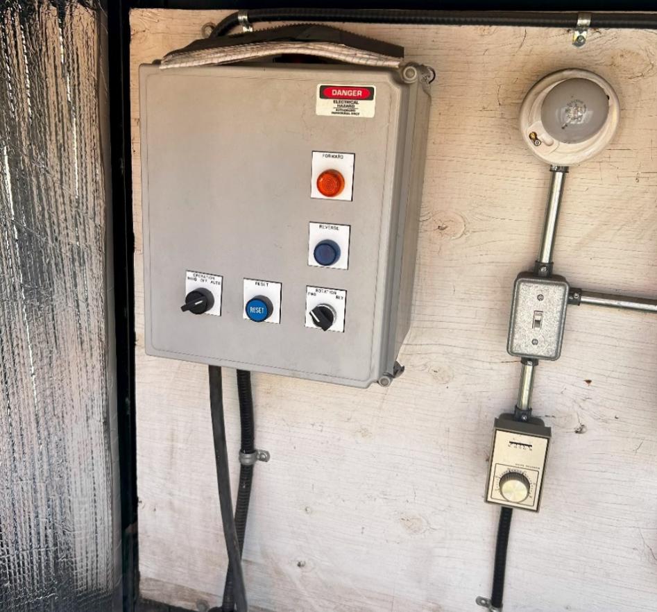
Proximity to Watercourses:
Description of Nearby Watercourse: Unknown
Flood of Record Elevation: Unknown
Flood Construction Level (FCL): Unknown
Lift Station Site Elevation: ~511.75m
Lift Station Flood Protection Measures: Unknown
Spill Protection Measures: Unknown
1. Record drawings and documents were not provided for this station and as such, assessment could not be completed. A schematic diagram was provided to show flow and station layout.
2. Precise location of station is unknown.
3. Grinder station does not have a standby generator, but transfer switch has been installed.
4. Grinder station does not have a flow meter or any communications or alarms. Operator would like a flow meter and alarms added, and emphasized the need for high water level alarm as the vault has flooded previously.
5. Grinder station installation date/age is unknown.
6. Site access is good according to operators.
7. Grinder station does not have any odour control.
1. A more thorough lift station assessment is recommended as records and data are incomplete and full recommended actions cannot be determined.
3. Add flow meter and alarms (especially high water alarm), and integrate with SCADA. Exlore oppurtunities to add flow meter so no confined space entry is required.
4. Review electrical and controls equipment, and if needed, upgrade in conjunction with instrumentation.
5. Add standby generator to lift station.
6. Investigate the cause or source of previous flooding to determine further recommendations for prevention.
Asset Type
(a) General Requirements
(b) Civil (Piping, Surface Works, Manhole)
(c) Structural (Building, Wet Well³, Valve Chamber)
(d) Process Mechanical (Pumps, Process Piping, Valves, Odour Control)
(e) Building Mechanical (HVAC, Blower, Hoists, Plumbing, Emergency Eyewash & Shower)
(f) Electrical & Controls (Starts / VFDs / Service, Cables and Wiring, Controls, Instrumentation, Lighting, Standby Generator)
Notes:
1. Estimated costs are a preliminary Class D estimate in 2025 dollars.
2. Replacement value also includes replacement value of above stated recommendations, assuming those have been or will be implemented at the next lift station upgrade / replacement.
3. For purpose of estimating the lift station's full replacement value, the wet well is included in the replacement value, regardless if it will or will not be replaced at the next upgrade / replacement.
Catchment area map not available.
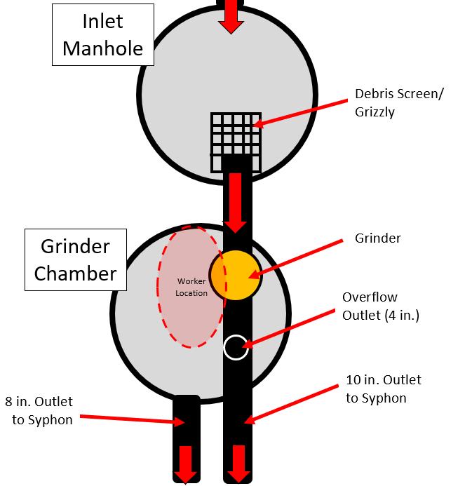
Pump performance curve not provided.
Year Installed: 2007
Municipal Address: 3271 King Road
Asset Number: LS#10
Catchment Area (ha): 14.8
Site Photo:
Service Population: 133 (current) 220 (20 Year Horizon Estimate)
Discharge Manhole: LV524
Last upgrade: 2021
Other Info:
Located in a cul-de-sac at the end of King Road in a residential area. Also known as Lakeview Phase 5-2. Catchment area has no contributing lift stations.
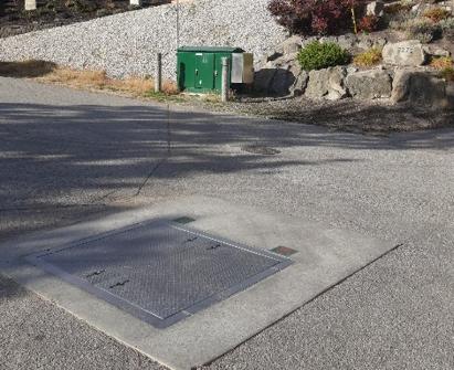
General Configuration: Below ground wet well and valves with duplex submersible pumps
Wet Well Material: Concrete
Wet Well Diameter (m): 1.8
Wet Well Height (m): 3.95
Wet Well Condition: Unknown
Inlet Pipe Material PVC
Inlet Pipe Size (mm): 200
Components:
VFDs: Unknown
Check Valve: Yes (50mm)
Isolation Valve: SS (50mm Stainless Steel Ball Valve)
Access Hatches: Yes
Emergency Response Items:
Standby Generator: No
Pump Bypass Connections: No
Portable Generator Connection: Yes (240V)
Emergency Suction: No Critical Spare Pump: Yes
Ladder: Yes
Platform: No
Odour Control: No
Ventilation: Yes (Goose Neck)
Wet Well Photo:Piping and Valving Photo:
HYDRAULIC STORAGE CAPACITY
Actual Operating Storage (L): Undetermined
Emergency Storage Volume (L)*: Undetermined LeadLagPumps OffHWL AlarmLWL Alarm
Emergency Storage Time - Current (mins)**: Undetermined Setpoints (%) 5060309525
Emergency Storage Time - Future (mins)**: Undetermined Setpoint Depth (m) UndeterminedUndeterminedUndeterminedUndeterminedUndetermined *High Water Alarm to sewer inlet pipe Volume (litres) UndeterminedUndetermined-Undetermined**at Maximum Day Flow
Pump #1Pump #2
230V230V
11
5.4 hp5.4 hp
Rotational Speed (rpm): 35003500
Make: FlygtFlygt
Model No.: MF3102HTMF3102HT
Impeller Number: 142142
Serial Number: 3102.170-06500613102.170-0650062
Install Year: 20212021
Flow Rate (L/s): 5.55.5 Design
Total Dynamic Head (m): 1616 Design
Flow Records Information (2022-2024 Data)
Domestic Flow Rate (DFR) (L/cap/day): Undetermined
FLOW RECORD INFORMATION
Pump Capacity (Max. Day Flow):
Average Day Flow (L/s): Undetermined
Maximum Day Flow (L/s) (Existing): 1.32 (Estimated from Modelling)
Maximum Day Flow (L/s) (20 Year): 1.83 (Estimated from Modelling)
Bylaw Flow Estimates
Average Dry Weather Flow - Current (L/s): 0.54 at 350 L/cap/day
Average Dry Weather Flow - Future (L/s): 0.89 at 350 L/cap/day
Pump Cycle Time - Current (2022-2024 Data) at Average Day Flow (min): Undetermined Starts per Hour (per Pump)*: Undetermined at Maximum Day Flow (min): Undetermined Starts per Hour (per Pump)*: Undetermined *Bylaw maximum pump starts - 4 times per hour per pump
Station Supply: 230V
STATION ELECTRICAL AND CONTROL
Instrumentation & Controls
Phase: 1 PLC: Direct Logic 205 D2-09B-1
Transformer Size (kVA): Unknown Flow Meter: No
Main Breaker (A): 100 Level Control: Yes (Militronics Bulbs)
UPS Power Capacity (VA): 1000
Generator
Pressure Transmitter: No
Pressure Gauge: No
SCADA Integration: Yes
Model: n/a Alarms Functioning: Yes
Power Rating (kW): n/a
Fuel Source: n/a
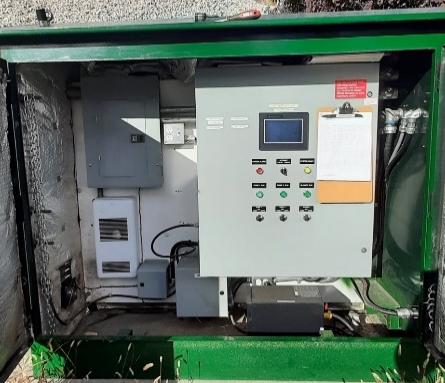
Measured Current Pulled by Pump Motor
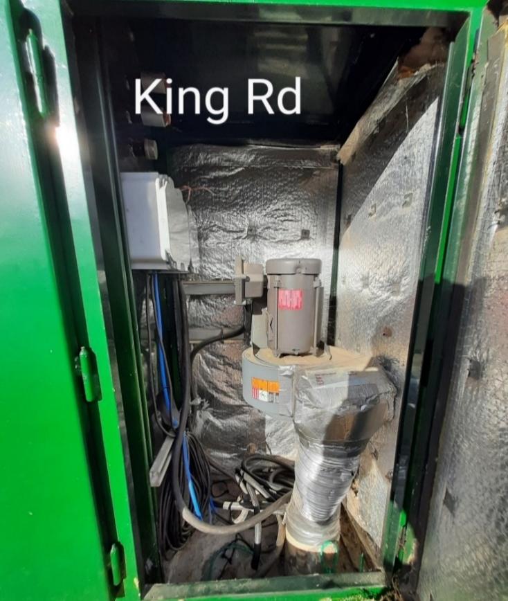
Proximity to Watercourses:
Description of Nearby Watercourse: None
Flood of Record Elevation: n/a
Flood Construction Level (FCL): n/a
Lift Station Site Elevation: 414.34m
Lift Station Flood Protection Measures: n/a
Spill Protection Measures: Each pump provides adequate capacity for peak day
1. Record drawings and pump curve from 2021 upgrade, as well as recent flow data and wet well photos, were not provided. As such, assessment of items such as emergency storage volumes, domestic flow rates, and pump capacities could not be determined.
2. Upgrade drawing from 2016 shows installation of large diameter pipe for additional emergency storage capacity and a Flygt pump replacement.
2. Lift station located in a cul-de-sac at the end of King Road in a residential area.
3. Valves (ball and check) are located in concrete wet well. Confined space entry required to operate.
4. Lift station does not have a standby generator but does have transfer switch and receptacle.
5. Lift station does not have a flow meter.
6. Lift station installed in 2007 (18 years old) with major renewal in 2021. Operators noted renewal included new pumps, pump rails, overflow tank, hatch lid, Miltronics and HMI screen.
7. Site access is good with no issues.
8. Lift station has no odour control.
1. Gather missing data to provide a more comprehensive assessment.
2. Although this station recently underwent renewal, piping and valves were not replaced. Consider moving valves to an above ground kiosk to eliminate confined space entry requirements.
3. Add flow meter to lift station with a future process mechanical upgrade. Flow meter to be located in above ground valve kiosk.
4. Assess electrical and controls equipment for remaining life expectancy and upgrade if needed.
5. Add standby generator to lift station with electrical equipment upgrades.
6. Review condition of existing concrete wet well to confirm condition. If found in unacceptable condition, replace, or an FRP slip lining upgrade could be installed if feasible.
7. Review additional safety considerations at time of renewal.
8. Odour control may need to be added with above ground valve chamber upgrade. To be confirmed at renewal.
9. Install emergency suction line in wet well and bypass connection on forcemain for emergencies.
10. Civil piping can be maintained. Consider isolation of wet well inflows with knife gate valve in wet well or upstream of lift station.
Asset Type
(a) General Requirements
(b) Civil (Piping, Surface Works, Manhole)
(c) Structural (Building, Wet Well³, Valve Chamber)
(d) Process Mechanical (Pumps, Process Piping, Valves, Odour Control)
(e) Building Mechanical (HVAC, Blower, Hoists, Plumbing, Emergency Eyewash & Shower) n/a (f) Electrical & Controls (Starts / VFDs / Service, Cables and Wiring, Controls, Instrumentation, Lighting)⁴
Notes:
1. Estimated costs are a preliminary Class D estimate in 2025 dollars.
2. Replacement value also includes replacement value of above stated recommendations, assuming those have been or will be implemented at the next lift station upgrade / replacement.
3. For purpose of estimating the lift station's full replacement value, the wet well is included in the replacement value, regardless if it will or will not be replaced at the next upgrade / replacement.
Consequence
Note:
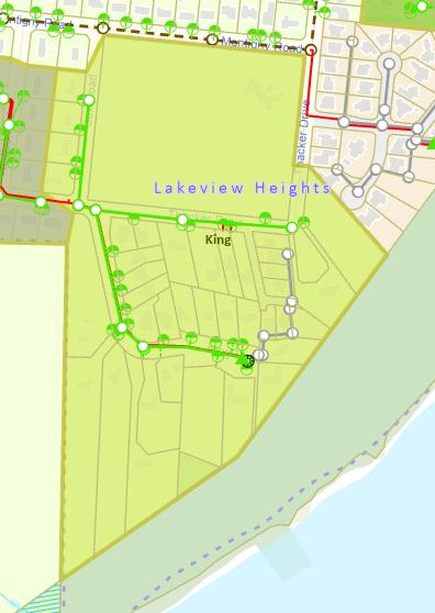
Note: 2021 upgrade record drawing not provided.
UPGRADE RECORD DRAWING (2016)
Pump performance curve for new pumps not provided (replaced in 2021).
IDENTIFICATION
Year Installed: 2002 (assumed) Site Photo:
Municipal Address: 2583 Whitworth Road
Asset Number: LS#11
Catchment Area (ha): 0.9
Service Population: 17 (current) 20 (20 Year Horizon Estimate)
Discharge Manhole: WR6
Last upgrade: Unknown
Other Info:
Located in Pebble Beach park. Catchment area has no contributing lift stations.
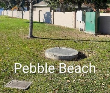
CONFIGURATION
General Configuration: Below ground wet well and valves with single submersible pump
Wet Well Material: Concrete
Wet Well Diameter (m): 1.2
Wet Well Height (m): 3.4
Emergency Response Items:
Standby Generator: No
Wet Well Condition: Unknown Pump Bypass Connections: No
Inlet Pipe Material PVC
Inlet Pipe Size (mm): 150
Components:
VFDs: No
Check Valve: No
Isolation Valve: No
Access Hatches: Yes
Portable Generator Connection: Yes
Emergency Suction: No Critical Spare Pump: No
Ladder: Yes
Platform: No
Odour Control: Yes (Injections)
Ventilation: No
Wet Well Photo:Piping and Valving Photo:
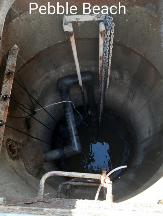
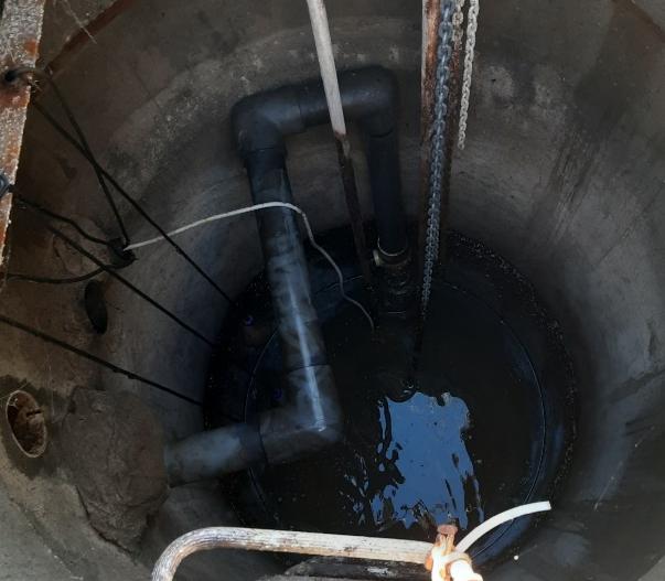
Actual Operating Storage (L): Undetermined
Emergency Storage Volume (L)*: Undetermined LeadLagPumps OffHWL AlarmLWL Alarm
Emergency Storage Time - Current (mins)**: Undetermined Setpoints (%) UnknownUnknownUnknownUnknownUnknown
Emergency Storage Time - Future (mins)**: Undetermined Setpoint Depth (m) UndeterminedUndeterminedUndeterminedUndeterminedUndetermined *High Water Alarm to sewer inlet pipe Volume (litres) UndeterminedUndetermined-Undetermined**at Maximum Day Flow
Pump #1Pump #2
Voltage: 230V
Phase: 3
Power: 3 hp
Rotational Speed (rpm): 3450
Make: Flygt
PUMP
Header
Pump Discharge Material: Unknown
Pump Discharge Size (mm): 75
Header Material: PVC
Header Size (mm): 75
Forcemain*
Model No.: MP3127HT Material: n/a
Impeller Number: 4.4"
Serial Number: 3102.170-9960069
Install Year: Unknown
Flow Rate (L/s): 13.7
Total Dynamic Head (m): 22.9
Flow Records Information (2022-2024 Data)
N/A
Domestic Flow Rate (DFR) (L/cap/day): Undetermined
Average Day Flow (L/s): Undetermined
Maximum Day Flow (L/s) (Existing): 0.13
Maximum Day Flow (L/s) (20 Year): 0.14
Bylaw Flow Estimates
Diameter (mm): n/a
Length (m): n/a
Forcemain Velocity (m/s): n/a
Design Retention Prior to Gravity (mins): n/a
Design *Note: Lift station discharges directly into 200mm PVC gravity main.
Pump Capacity (Max. Day Flow):
(Estimated from Modelling)
(Estimated from Modelling)
Average Dry Weather Flow - Current (L/s): 0.07 at 350 L/cap/day
Average Dry Weather Flow - Future (L/s): 0.08 at 350 L/cap/day
Pump Cycle Time - Current (2022-2024 Data)
at Average Day Flow (min): Undetermined Starts per Hour (per Pump)*: Undetermined at Maximum Day Flow (min): Undetermined
Starts per Hour (per Pump)*: Undetermined *Bylaw maximum pump starts - 4 times per hour per pump
Station Supply: 240V
Instrumentation & Controls
Phase: 1 PLC: Direct Logic 06 D0-06DR
Transformer Size (kVA): Unknown
Main Breaker (A): 10
UPS Power Capacity (VA): 1000
Generator
Model: n/a
Power Rating (kW): n/a
Fuel Source: n/a
Flow Meter: No
Level Control: Yes (Vega Pulse C21)
Pressure Transmitter: No
Pressure Gauge: No
SCADA Integration: No
Alarms Functioning: Yes
Measured Current Pulled by Pump Motor
9.93An/a Left leg (T1)
9.7An/a Middle leg (T2)
Unknownn/a Right leg (T3)
Controller Photo:Injection
Dosing Photo:
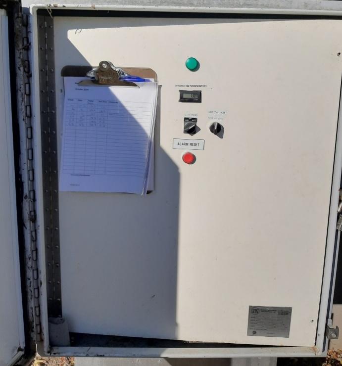
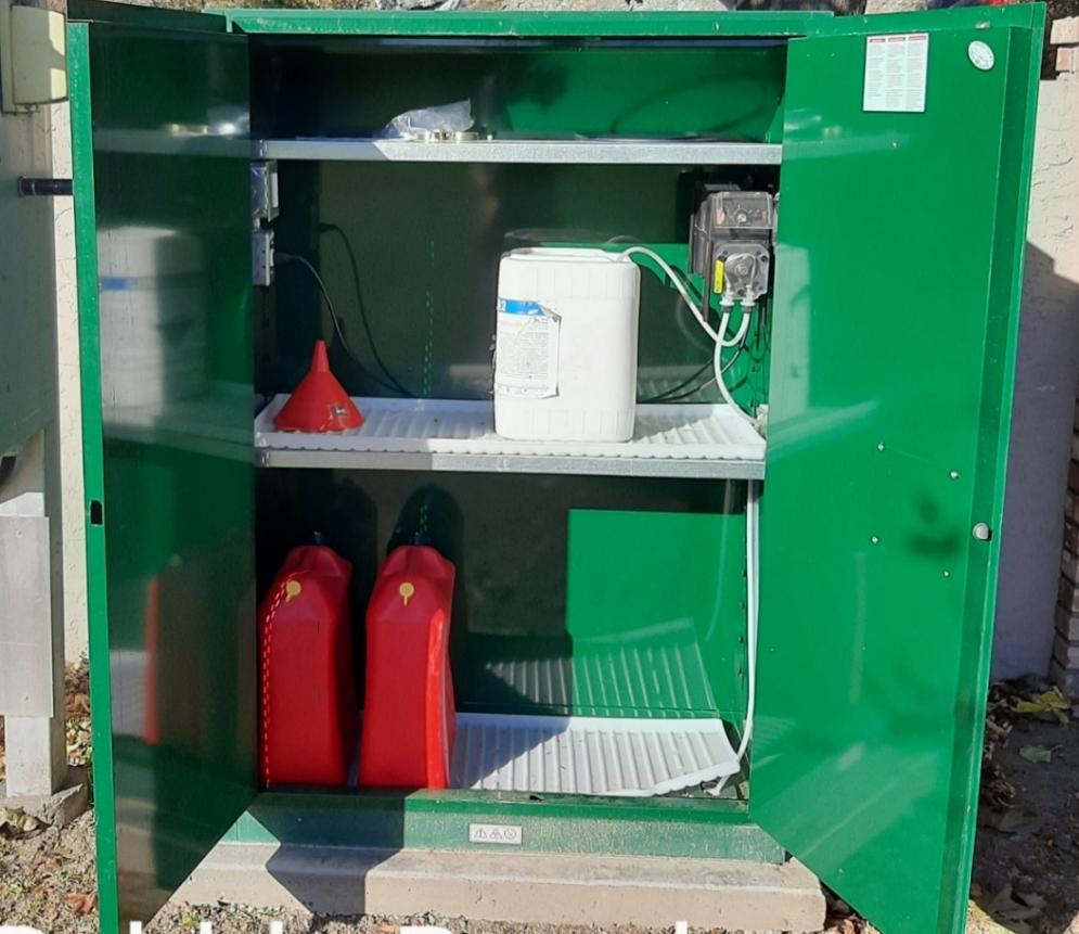
Proximity to Watercourses:
Spill
1. Record drawings and pump curves were not provided for this lift station. Assessment of items such as emergency storage volumes and domestic flow rates could not be determined.
2. Small lift station for a few condos, located in Pebble Beach Park near Okanagan Lake. Site is behind park fence and surrounded by lawn.
3. There no plug or check valves according to the operators.
4. Lift station only operates with one pump and there is no critical spare. There is also no standby generator or transfer switch.
5. Lift station does not have a flow meter.
6. Lift station assumed to be installed in 2002. Currently going through a minor upgrade to add odour control, communication, level transmitter and connecting to SCADA.
7. Lift station receives calcium nitrate injections (BioMaxx) for odour control.
8. Site access is challenging as lawn around lift station is often saturated from sprinklers and there is no driveway for heavy equipment, such as vac-truck.
9. Higher priority for operators due to lift station's proximity to Okanagan Lake.
1. A more thorough lift station assessment is recommended as records and data are incomplete, and full recommended actions could not be completed.
2. Add valves to an above ground valve kiosk to eliminate confined space entry requirements. Procure critical spare pump at this time.
3. Add flow meter to lift station with a future process mechanical upgrade. Flow meter to be located in above ground valve kiosk.
4. Consider upgrading electrical and controls equipment in conjunction with future process mechanical upgrade.
5. Review need for standby generator and add if needed. Consider installing a transfer switch.
6. Review condition of existing concrete wet well to confirm condition. If found in unacceptable condition, replace, or an FRP slip lining upgrade could be installed if feasible.
7. Review additional safety considerations at time of renewal, such as new hatches with safety grates.
8. Install emergency suction line in wet well and bypass connection on forcemain for emergencies.
9. Civil piping can be maintained. Consider isolation of wet well inflows with knife gate valve in wet well or upstream of lift station.
10. Improve site access to lift station for heavier equipment. Hard surface (asphalt or gravel) or subsurface grass reinforcement as lift station is within a public park. Or improve access from parking lot with fence openings / gate and surface improvements for large equiprment.
Notes:
1. Estimated costs are a preliminary Class D estimate in 2025 dollars.
2. Replacement value also includes replacement value of above stated recommendations, assuming those have been or will be implemented at the next lift station upgrade / replacement.
3. For purpose of estimating the lift station's full replacement value, the wet well is included in the replacement value, regardless if it will or will not be replaced at the next upgrade / replacement.
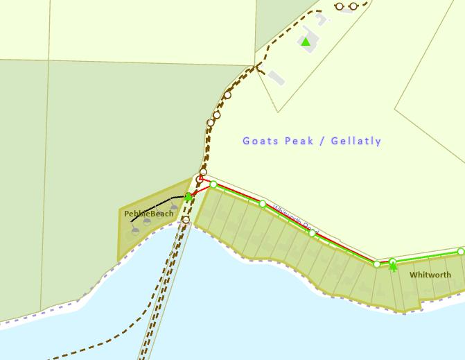
Record drawing not provided.
Pump performance curve not provided.
IDENTIFICATION
Year Installed: 2000 Site Photo:
Municipal Address: 4081 Hitchner Road
Asset Number: LS#12
Catchment Area (ha): 6.9
Service Population: 67 (current) 73 (20 Year Horizon Estimate)
Discharge Manhole: ET32
Last upgrade: Unknown
Other Info:
at the entrance to Hitchner Park beach access at the corner of Hitchner Road and Jennens Road. Also known as Hitchner-Jennens. Catchment area has no contributing lift stations.
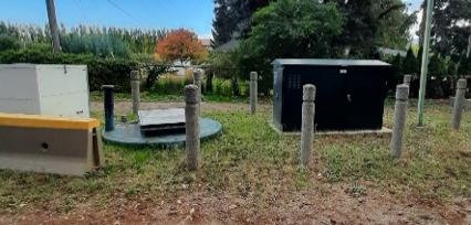
CONFIGURATION
General Configuration: Below ground wet well and valves with duplex submersible pumps
Wet Well Material: FRP
Wet Well Diameter (m): 2.4
Wet Well Height (m): 7.2
Emergency Response Items:
Wet Well Condition: Unknown Pump Bypass Connections: No
Inlet Pipe Material PVC
Inlet Pipe Size (mm): 200
Components:
VFDs: No
Generator Connection: Yes (600V)
Suction: Yes
Spare Pump: Yes
Ladder: Yes
Check Valve: Yes (75mm HDL Check Valve) Platform: Yes
Isolation Valve: Yes (75mm Cast Iron Plug Valve)
Access Hatches: Yes (Aluminum)
Odour Control: Yes (on Exhaust Vent Pipe)
Ventilation: Yes
Wet Well Photo:Piping and Valving Photo:
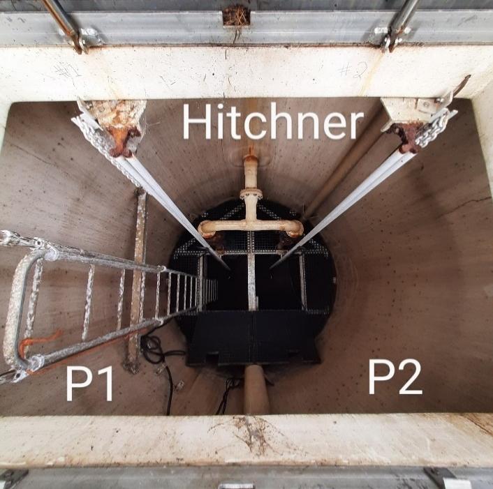
#1Pump #2
33
FRP Power: 6 hp6 hp
Rotational Speed (rpm): 35003500
Make: FlygtFlygt
Model No.: MP3127HTMP3127HT
Impeller Number: UnknownUnknown
Serial Number:
(63-212-005200)
(63-21200-5200)
Flow Rate (L/s): 6.36.3 Design
Flow Records Information (2022-2024 Data)
Domestic Flow Rate (DFR) (L/cap/day): 171
Average Day Flow (L/s): 0.13
Maximum Day Flow (L/s) (Existing): 0.93 (Estimated from Modelling)
Maximum Day Flow (L/s) (20 Year): 0.97 (Estimated from Modelling)
Bylaw Flow Estimates
Average Dry Weather Flow - Current (L/s): 0.27 at 350 L/cap/day
Average Dry Weather Flow - Future (L/s): 0.30 at 350 L/cap/day
Pump Cycle Time - Current (2022-2024 Data) at Average Day Flow (min): 580.06 Starts per Hour (per Pump)*: 0.05 at Maximum Day Flow (min): 95.11 Starts per Hour (per Pump)*: 0.3 *Bylaw maximum pump starts - 4 times per hour per pump
Pump Capacity (Max. Day Flow):
Station Supply: 600V Instrumentation & Controls
Transformer Size (kVA): 5
Breaker (A): 100
Control:
(Militronic Bulb) UPS Power Capacity (VA): 1000 Pressure Transmitter: No
Pressure Gauge: No Generator SCADA Integration: Yes Model: n/a Alarms Functioning: Yes
Power Rating (kW): n/a Fuel Source: n/a
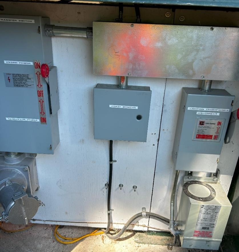
Measured Current Pulled by Pump Motor
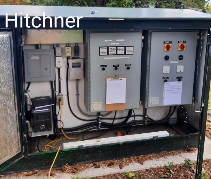
Proximity to Watercourses:
Description of Nearby Watercourse: Okanagan Lake
Flood of Record Elevation: 343.25m (Okanagan Basin Water Board)
Flood Construction Level (FCL): 343.66m (CoWK Bylaw No. 265)
Lift Station Site Elevation: 346.46m
Lift Station Flood Protection Measures: Above Flood Construction Level
Spill Protection Measures: Each pump provides adequate capacity for peak day
1. Lift station located at the entrance to Hitchner Park beach access at the corner of Hitchner and Jennens Roads. Site is protected by bollards.
2. Valves (plug and check) are located in wet well. Confined space entry required to operate.
3. Lift station does not have a standby generator. Emergency storage for this lift station is 995 L (approx. 17 minutes) at maximum day flow. Inadequate for response.
4. Lift station does not have a flow meter.
5. Lift station is aging (25 years old - 2000) with no major renewal.
6. Forcemain velocity is only 0.8 m/s and does not meet the City bylaw minimum (1.0 m/s)
7. Pump curve shows overall efficiency is approx. 21% operating at the best efficiency point.
8. A high water table event occurred in 2017 or 2018 created a forcemain break. Forcemain was repaired with a robar coupling.
9. Operators reported that site access is good and lift station appears to be working well.
10. Lift station has odour control on exhaust vent.
11. Higher priority for operators due to lift station's proximity to Okanagan Lake.
1. Replace aged process mechanical equipment (pumps, piping, and valves). Valves to be in above ground valve chamber (Barski).
2. Review pump selection at time of renewal to select a pump with improved efficiency.
3. Add flow meter to lift station with process mechanical upgrade. Flow meter to be located in above ground valve chamber.
4. Upgrade aged electrical and controls equipment in conjunction with process mechanical upgrade. Include SCADA alarms.
5. Review need for standby generator and add if needed.
6. Complete testing of existing wet well to confirm condition (can be provided by Barski). If found in acceptable condition, wet well can remain.
7. Review additional safety considerations at time of renewal, such as new hatches with safety grates.
8. Existing odour control may need to be upgraded with above ground valve chamber upgrade. To be confirmed at renewal.
9. Install bypass connection on forcemain for emergencies.
10. Civil piping can be maintained. Consider isolation of wet well inflows with knife gate valve in wet well or upstream of lift station.
11. Consider increasing pump flow rate on next upgrade to increase forcemain velocities, so that minimum scouring velocity is met.
(a) General Requirements
(b) Civil (Piping, Surface Works, Manhole)
(c) Structural (Building, Wet Well³, Valve Chamber)
(d) Process Mechanical (Pumps, Process Piping, Valves, Odour Control)
(e) Building Mechanical (HVAC, Blower, Hoists, Plumbing, Emergency Eyewash & Shower) n/a (f) Electrical & Controls (Starts / VFDs / Service, Cables and Wiring, Controls, Instrumentation, Lighting)⁴
Notes:
1. Estimated costs are a preliminary Class D estimate in 2025 dollars.
2. Replacement value also includes replacement value of above stated recommendations, assuming those have been or will be implemented at the next lift station upgrade / replacement.
3. For purpose of estimating the lift station's full replacement value, the wet well is included in the replacement value, regardless if it will or will not be replaced at the next upgrade / replacement.
4. Standby generator not included in replacement cost.
Note:
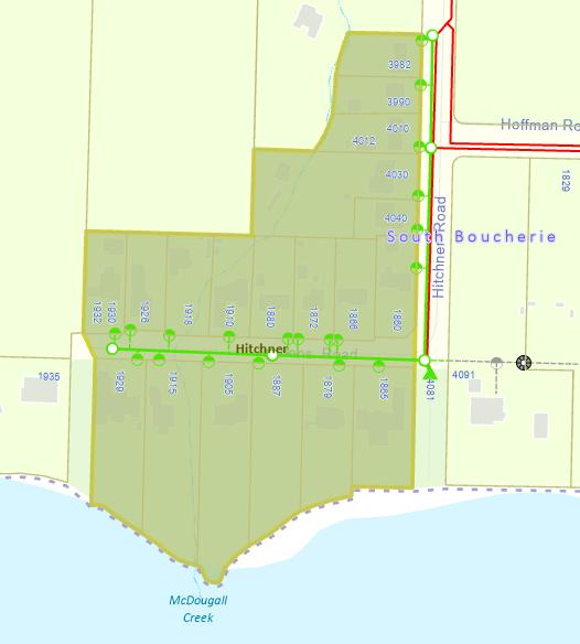
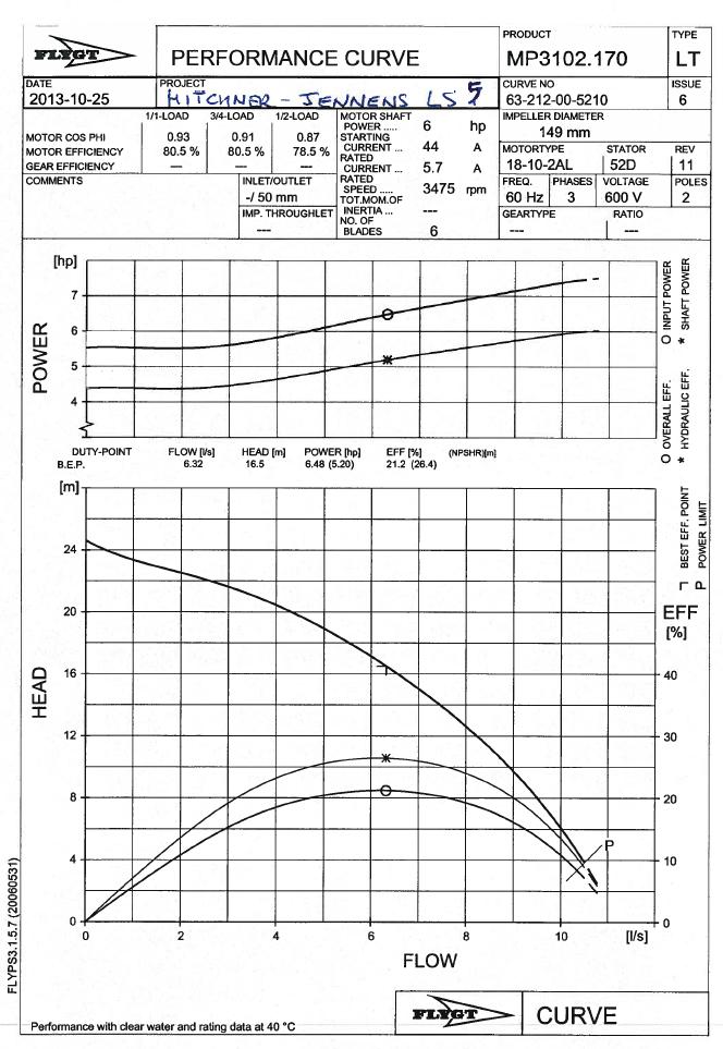

Year Installed: 2007
Municipal Address: 1210 Sunnybrae Road
Asset Number: LS#13
Catchment Area (ha): 2.2
IDENTIFICATION
Site Photo:
Service Population: 28 (current) 31 (20 Year Horizon Estimate)
Discharge Manhole: SS212
Last upgrade: Unknown
Other Info:
Located in the cul-de-sac of Sunnybrae Road. Catchment area has no contributing lift stations.
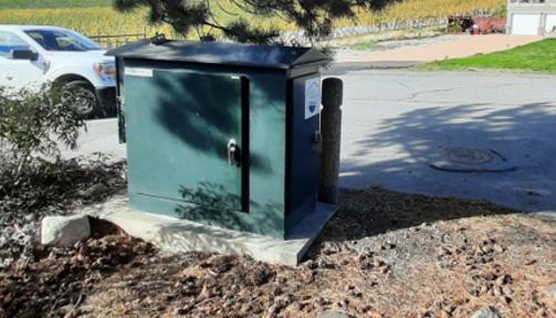
General Configuration: Below ground wet well and valves with duplex submersible pumps
Wet Well Material: Concrete
Wet Well Diameter (m): 1.8
Wet Well Height (m): 4.06
Wet Well Condition: Unknown
Inlet Pipe Material Unknown
Inlet Pipe Size (mm): 200
Components:
VFDs: No
Check Valve: Yes
Isolation Valve: No
Access Hatches: Manhole
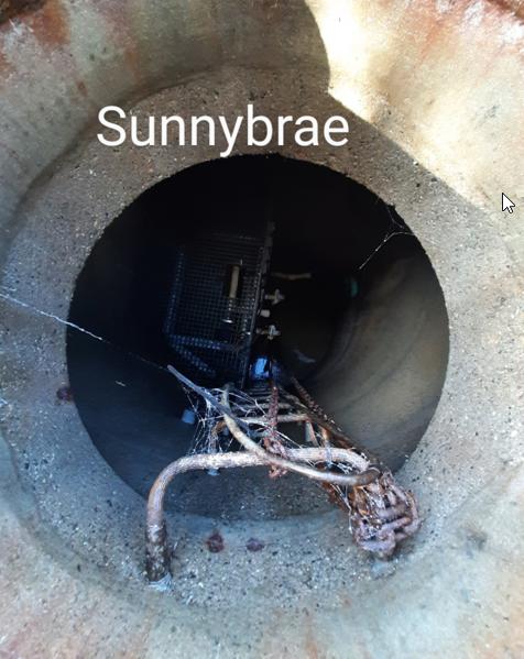
Actual Operating Storage (L): Undetermined
Emergency Response Items:
Standby Generator: No
Pump Bypass Connections: No
Portable Generator Connection: Yes (600V)
Emergency Suction: No Critical Spare Pump: Yes
Ladder: Yes
Platform: Yes
Odour Control: No
Ventilation: No
Wet Well Photo:Piping and Valving Photo:
CONFIGURATION HYDRAULIC STORAGE CAPACITY
Emergency Storage Volume (L)*: Undetermined LeadLagPumps OffHWL AlarmLWL Alarm
Emergency Storage Time - Current (mins)**: Undetermined Setpoints (%) UnknownUnknownUnknownUnknownUnknown
Emergency Storage Time - Future (mins)**: Undetermined Setpoint Depth (m) UndeterminedUndeterminedUndeterminedUndeterminedUndetermined *High Water Alarm to sewer inlet pipe Volume (litres) UndeterminedUndetermined-Undetermined**at Maximum Day Flow
Pump #1Pump #2
Voltage: 575V575V
Phase: 33
Power: 3 hp3 hp
Rotational Speed (rpm): 34503450
Make: GouldsGoulds
Model No.:
4RCX400M2-534RCX400M2-53
Impeller Number: 26605C51626605C516
Serial Number: UnknownUnknown
Install Year: UnknownUnknown
Header
Pump Discharge Material: Unknown
Pump Discharge Size (mm): Unknown
Header Material: Unknown
Header Size (mm): Unknown
Forcemain
Material:
Diameter (mm): 50
Length (m): 191
Forcemain Velocity (m/s)*: Undetermined
Flow Rate (L/s): UnknownUnknown Design Retention Prior to Gravity (mins): Undetermined
Total Dynamic Head (m): UnknownUnknown Design
Flow Records Information (2022-2024 Data)
Domestic Flow Rate (DFR) (L/cap/day): Undetermined
Average Day Flow (L/s): Undetermined
*Bylaw velocities: min. 1 m/s, max. 3.5m/s
Pump Capacity (Max. Day Flow):
Maximum Day Flow (L/s) (Existing): 0.25 (Estimated from Modelling)
Maximum Day Flow (L/s) (20 Year): 0.26 (Estimated from Modelling)
Bylaw Flow Estimates
Average Dry Weather Flow - Current (L/s): 0.11 at 350 L/cap/day
Average Dry Weather Flow - Future (L/s): 0.13 at 350 L/cap/day
Pump Cycle Time - Current (2022-2024 Data) at Average Day Flow (min): Undetermined
Starts per Hour (per Pump)*: Undetermined at Maximum Day Flow (min): Undetermined
*Bylaw maximum pump starts - 4 times per hour per pump
Starts per Hour (per Pump)*: Undetermined
Station Supply: 575V
Instrumentation & Controls Phase: 3 PLC:
Direct Logic 05 D0-05DR
Transformer Size (kVA): Unknown Flow Meter: No
Main Breaker (A): 100
UPS Power Capacity (VA): 1000
Generator
Model: n/a
Power Rating (kW): n/a
Fuel Source: n/a
Level Control: Yes (Floats)
Pressure Transmitter: No
Pressure Gauge: No
SCADA Integration: No
Alarms Functioning: No
Measured Current Pulled by Pump Motor
No.1No.2
T1 6.28A7.53A Left leg (T1) T2 6.3A6.64A Middle leg (T2) T3 6.15A7.32A Right leg (T3)
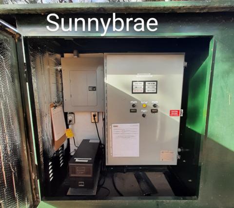
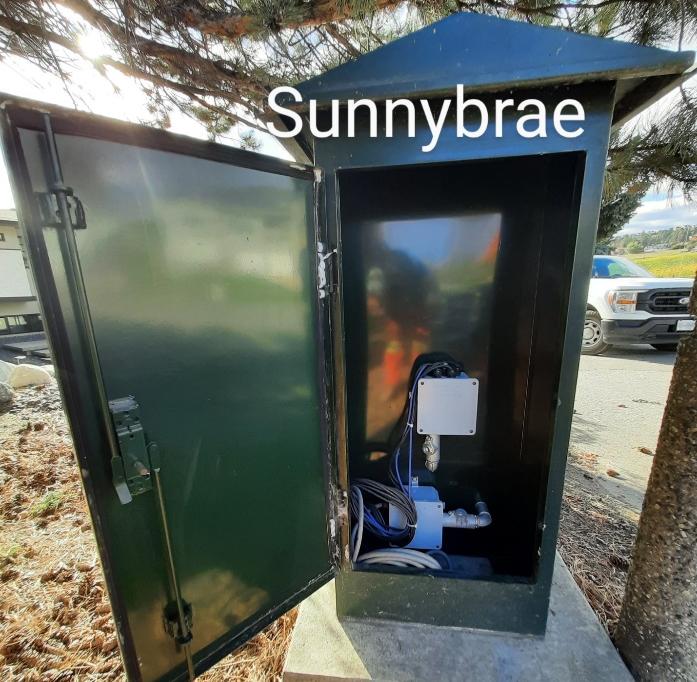
Proximity to Watercourses:
Description of Nearby Watercourse: None Flood of Record Elevation: n/a Flood Construction Level (FCL): n/a
Lift Station Site Elevation: ~362.45m
Lift Station Flood Protection Measures: n/a
Spill Protection Measures: Not enough information to determine if each pump provides adequate capacity for peak day
1. Record drawings, pump curves and setpoints were not provided for this lift station. Assessment of items such as emergency storage volumes, domestic flow rates, and pump capacities could not be determined.
2. Lift station located in the middle of the cul-de-sac of Sunnybrae Road. Operators noted it is a small simple system, but has limited acces under the manhole lid.
3. Valves (assumed) are located in concrete wet well. Confined space entry required to operate.
4. Lift station does not have a standby generator.
5. Lift station does not have a flow meter and no SCADA alarms.
6. Lift station is aging (18 years old - 2007) with no major renewal.
7. Site access is good.
8. Lift station does not have odour control.
9. Operators noted this lift station will need attention in the future but it is a low priority.
1. A more thorough lift station assessment is recommended as records and data are incomplete.
2. Assess condition of mechanical process equipment (pumps, piping, and valves), as they are nearing their end of life, and determine remaining life expectancy. If replacement is required, valves to be in above ground valve kiosk and add pump guide rails and stainless steel header.
3. Add flow meter to lift station with process mechanical upgrade. Flow meter to be located in above ground valve kiosk.
4. Upgrade aging electrical and controls equipment in conjunction with process mechanical upgrade. Include SCADA alarms.
5. Review need for standby generator and add if needed.
6. Review condition of existing concrete wet well to confirm condition. If found in unacceptable condition, replace, or an FRP slip lining upgrade could be installed if feasible.
7. Review additional safety considerations at time of renewal, such as manhole lid replacement with a double-winged road rated hatch.
8. Odour control may need to be added with above ground valve chamber upgrade. To be confirmed at renewal.
9. Install emergency suction line in wet well and bypass connection on forcemain for emergencies.
10. Civil piping can be maintained. Consider isolation of wet well inflows with knife gate valve in wet well or upstream of lift station.
(b) Civil (Piping, Surface Works, Manhole)
(c) Structural (Building, Wet Well³, Valve Chamber)
(d) Process Mechanical (Pumps, Process Piping, Valves, Odour Control)
(e) Building Mechanical (HVAC, Blower, Hoists, Plumbing, Emergency Eyewash & Shower) n/a (f) Electrical & Controls (Starts / VFDs / Service, Cables and Wiring, Controls, Instrumentation, Lighting)⁴
Notes:
1. Estimated costs are a preliminary Class D estimate in 2025 dollars.
2. Replacement value also includes replacement value of above stated recommendations, assuming those have been or will be implemented at the next lift station upgrade / replacement.
3. For purpose of estimating the lift station's full replacement value, the wet well is included in the replacement value, regardless if it will or will not be replaced at the next upgrade / replacement.
4. Standby generator not included in replacement cost.
Note: The condition assessment findings are based on background information, documentation, photos, and record drawings provided by the City, and discussions with City operators. No site visits were completed to physically assess the condition of the lift stations. As such, the quality of condition assessment findings is dependent on the quality of data provided to McElhanney, and may not fully represent site conditions.
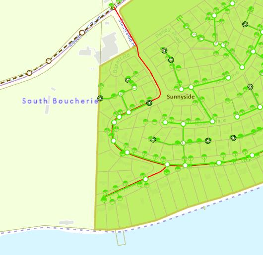
Record drawing not provided.
Pump performance curve not provided.
Year Installed: 2007
Municipal Address: 3192 Thacker Drive
Asset Number: LS#14
Catchment Area (ha): 3.2
IDENTIFICATION
Service Population: 66 (current) 109 (20 Year Horizon Estimate)
Discharge Manhole: LV524
Last upgrade: Unknown
Other Info:
in a cul-de-sac at the end of Thacker Drive. Also known as Lakeview Phase 5-1. Catchment area has no contributing lift stations.
CONFIGURATION
General Configuration: Below ground wet well and valves with duplex submersible pumps
Wet Well Material: Concrete
Wet Well Diameter (m): 1.8
Wet Well Height (m): 6.1
Emergency Response Items:
Standby Generator: No
Wet Well Condition: Good Pump Bypass Connections: No
Inlet Pipe Material PVC Portable Generator Connection: Yes (240V)
Inlet Pipe Size (mm): 200 Emergency Suction: No Critical Spare Pump: Yes
Components:
VFDs: No
Check Valve: Yes (50mm Model Unknown)
Isolation Valve: Yes (SS Ball)
Access Hatches: Yes (MH Frame and Cover)
Ladder: Yes
Platform: No
Odour Control: No
Ventilation: Yes Wet Well Photo:Piping and Valving Photo:
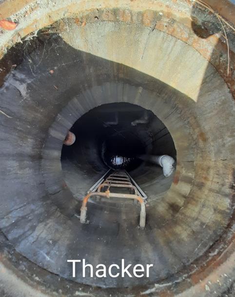
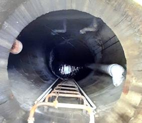
3 hp3 hp
Speed (rpm): 34503450 Make: FlygtFlygt
Model No.: MF3085MF3085
Flow Records Information (2022-2024 Data) Pump Capacity (Max. Day Flow):
Domestic Flow Rate (DFR) (L/cap/day): Undetermined
Average Day Flow (L/s): Undetermined Maximum Day Flow (L/s) (Existing): 0.47 (Estimated from Modelling) Maximum Day Flow (L/s) (20 Year): 0.69 (Estimated from Modelling)
Bylaw Flow Estimates
Average Dry Weather Flow - Current (L/s): 0.27 at 350 L/cap/day
Average Dry Weather Flow - Future (L/s): 0.44 at 350 L/cap/day
Pump Cycle Time - Current (2022-2024 Data) at Average Day Flow (min): Undetermined Starts per Hour (per Pump)*: Undetermined at Maximum Day Flow (min): 52.79 Starts per Hour (per Pump)*: 0.6
*Bylaw maximum pump starts - 4 times per hour per pump
Station Supply: 240V
Phase: 1
AND CONTROL
Instrumentation & Controls
Transformer Size (kVA): Unknown Flow Meter: No
Main Breaker (A): 100 Level Control: Yes (Flygt Bulb Level)
UPS Power Capacity (VA): 1000 (not working)
Generator
Pressure Transmitter: No
Pressure Gauge: No
SCADA Integration: Yes
Model: n/a Alarms Functioning: Yes
Power Rating (kW): n/a
Fuel Source: n/a
Kiosk - Electrical & Control
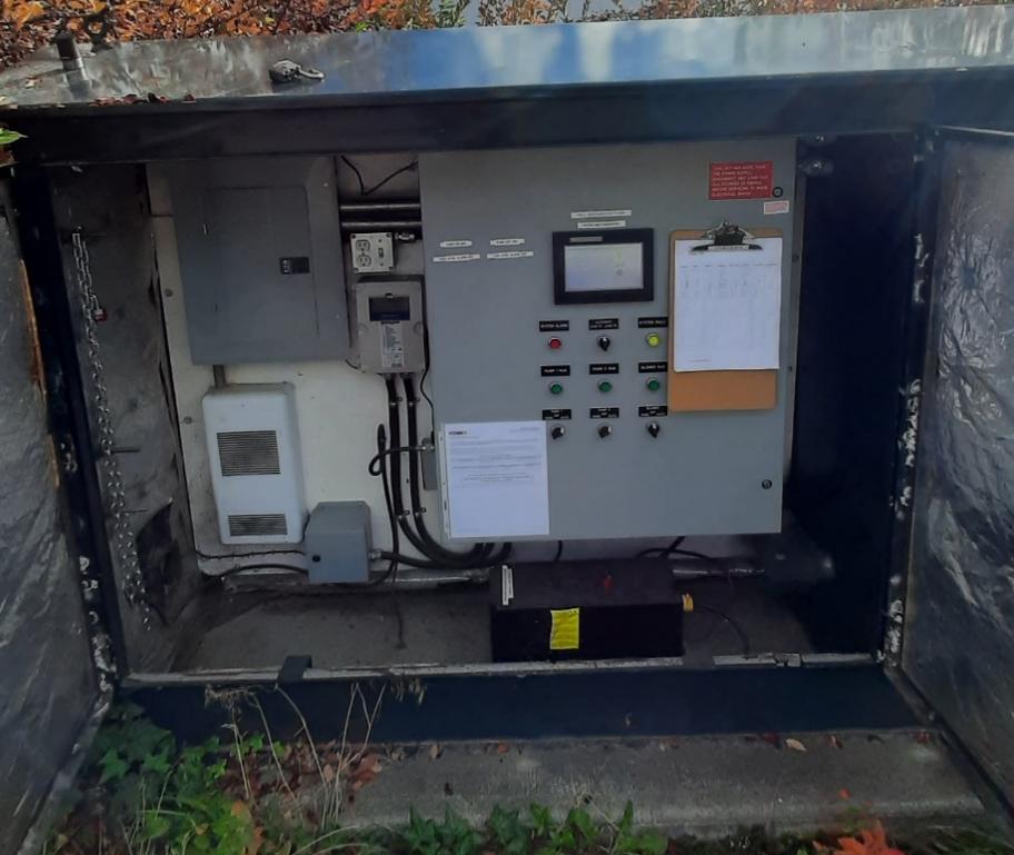
Measured Current Pulled by Pump Motor
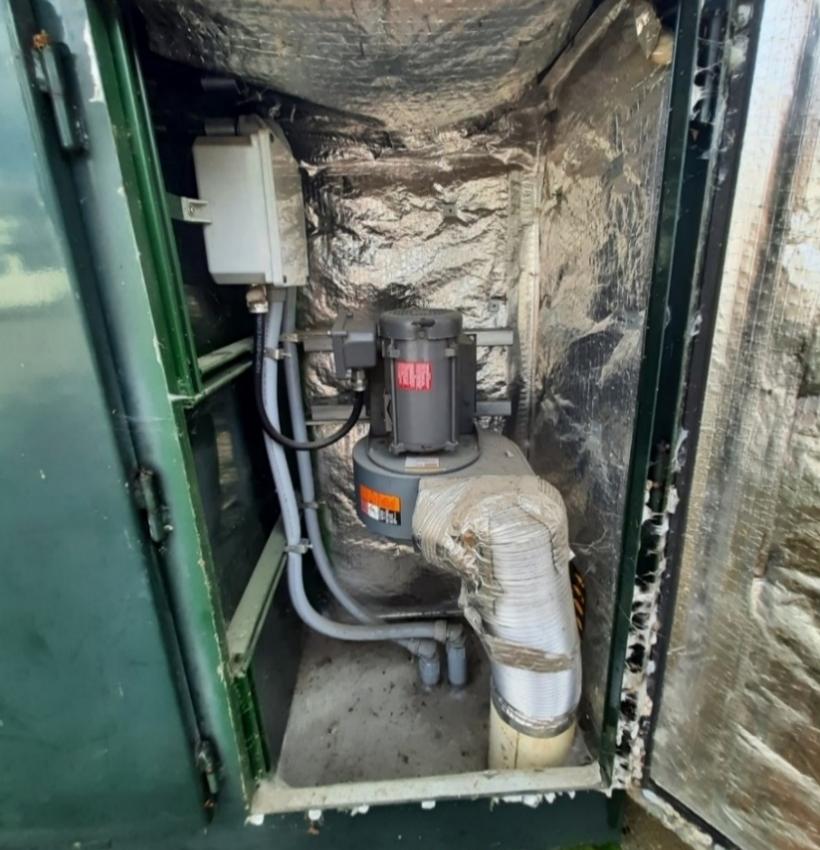
Proximity to Watercourses:
Description of Nearby Watercourse: None
Flood of Record Elevation: n/a
Flood Construction Level (FCL): n/a
Lift Station Site Elevation: 426.43m
Lift Station Flood Protection Measures: n/a
Lift station was assessed on October 15, 2025 as part of another project. Field observations noted here.
1. Lift station located in a concrete manhole in the middle of a cul-de-sac at the end of Thacker Drive with good access.
2. Valves (ball and check) are located in concrete wet well. Confined space entry required to operate.
3. Lift station does not have a standby generator. There is no emergency storage as HWL alarm is above inlet pipe.
4. Lift station aged (18 years old - 2007) with no major renewal. Generally in good condition.
5. Lift station does not have a flow meter. Pump drawdown test completed to determine pumping rates for each pump.
6. Pump curve shows overall efficiency at approx. 17%, close to its best efficiency point.
7. Lift station has no odour control. No odour issues noted.
8. Lift station has soft discharge tubes coming up to a header with cam lock, which Operators have noted they would like replaced.
9. Pumps have no guide rail system, so confined space entry is required to change out pumps. Due to the confined nature of this lift station, operators require entry on a swing chair, which is difficult.
10. Operators would like the manhole lid replaced with a double-winged road rated hatch to provide better access to the wet well.
1. Upgrade pumps with guide rail system and add double-winged road rated hatch with safety grates, so operators can complete maintenance and change out pumps without having to access the wet well with a swing chair. Addresses immediate confined space entry concerns.
2. Review pump selection at time of renewal to select a pump with improved efficiency.
3. Add valves to above ground valve chamber to eliminate confined space entry at next upgrade. Mechanical process equipment (pumps, piping, and valves) generally in good condition, so an immediate upgrade not requied.
4. Add flow meter to lift station with process mechanical upgrade. Flow meter to be located in above ground valve kiosk.
5. Upgrade electrical and controls equipment in conjunction with process mechanical upgrade. PLC may require an earlier upgrade as becoming outdated.
6. Add standby generator to lift station with electrical equipment upgrades.
7. Review condition of existing concrete wet well at next upgrade. Currently in good condition. If significant deterioration in condition found at next upgrade, replace, or an FRP slip lining upgrade could be installed if feasible.
8. Review additional safety considerations at time of renewal.
9. Odour control may need to be added with above ground valve chamber upgrade. To be confirmed at renewal.
10. Install emergency suction line in wet well and bypass connection on forcemain for emergencies.
11. Civil piping can be maintained, but additional forcemain piping will be required once an above ground valve kiosk is added.
12. Consider isolation of wet well inflows with knife gate valve in wet well or upstream of lift station.
13. Calibrate level control settings, so percentages are representative of wet well depth.
Spill Protection Measures: Each pump provides adequate capacity for peak day Asset Type
(a) General Requirements
(b) Civil (Piping, Surface Works, Manhole)
(c) Structural (Building, Wet Well³, Valve Chamber)
(d) Process Mechanical (Pumps, Process Piping, Valves, Odour Control)
(e) Building Mechanical (HVAC, Blower, Hoists, Plumbing, Emergency Eyewash & Shower) n/a (f) Electrical & Controls (Starts / VFDs / Service, Cables and Wiring, Controls, Instrumentation, Lighting)⁴
Notes:
1. Estimated costs are a preliminary Class D estimate in 2025 dollars.
2. Replacement value also includes replacement value of above stated recommendations, assuming those have been or will be implemented at the next lift station upgrade / replacement.
3. For purpose of estimating the lift station's full replacement value, the wet well is included in the replacement value, regardless if it will or will not be replaced at the next upgrade / replacement.
Note:
The condition assessment findings are based on a field site assessment, background information, documentation, photos, and record drawings provided by the City, and discussions with City operators. The quality of condition assessment findings is dependent on the quality of data provided to McElhanney, and may not fully represent site conditions.
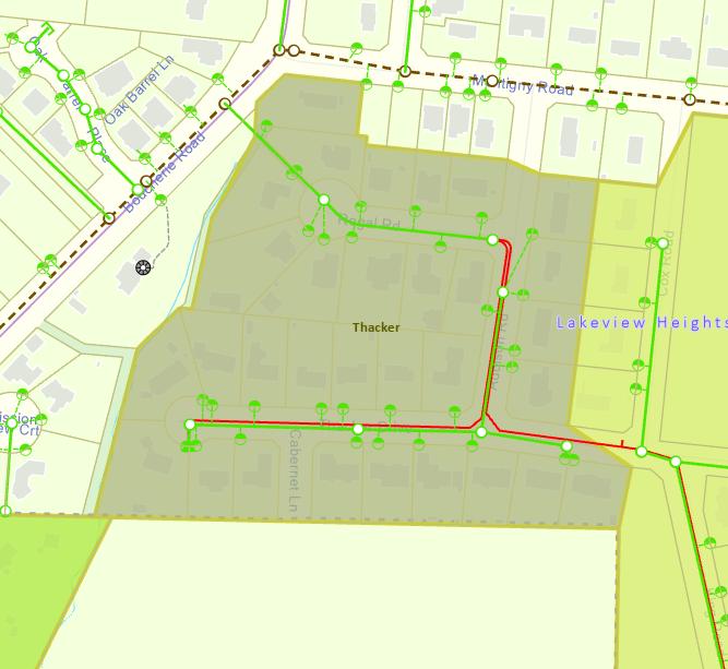
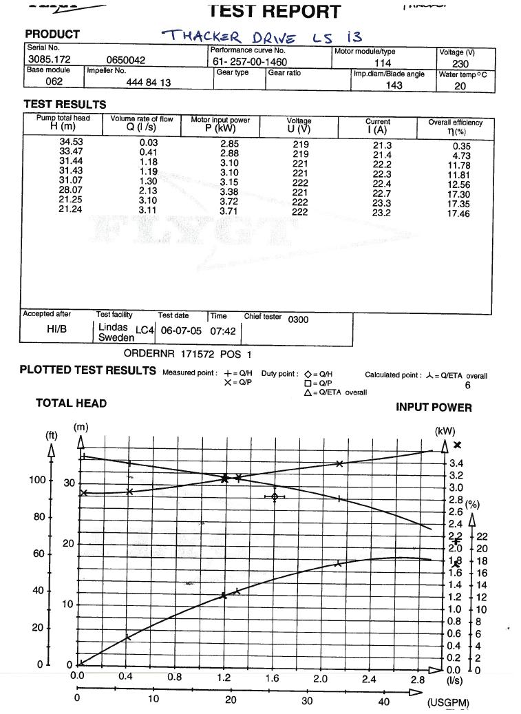
Year Installed: 2000
Municipal Address: 1750 Keloka Drive
Asset Number: LS#15
Catchment Area (ha): 1.7
Service Population: 31 (current) 33 (20 Year Horizon Estimate)
Discharge Manhole: WKCO
Last upgrade: 2015
Other Info:
Located on private property (921 Pinewood Place) in a residential area. Also known as Keloka Drive Prefab. Catchment area has no contributing lift stations.
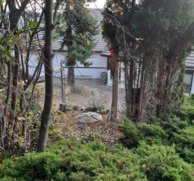
CONFIGURATION
General Configuration: Below ground wet well and valves with duplex submersible pumps
Wet Well Material: Unknown
Wet Well Diameter (m): Unknown
Emergency Response Items:
Wet Well Height (m): Unknown Standby Generator: No
Wet Well Condition: Unknown
Inlet Pipe Material Unknown
Inlet Pipe Size (mm): Unknown
Components:
VFDs: No
Check Valve: No
Isolation Valve: Yes (38mm Stainless Steel Ball Valve)
Access Hatches: Yes (FRP)
Pump Bypass Connections: No
Portable Generator Connection: No
Emergency Suction: No Critical Spare Pump: Yes
Ladder: No
Platform: No
Odour Control: No
Ventilation: No
Wet Well Lid:Piping and Valving Photo:
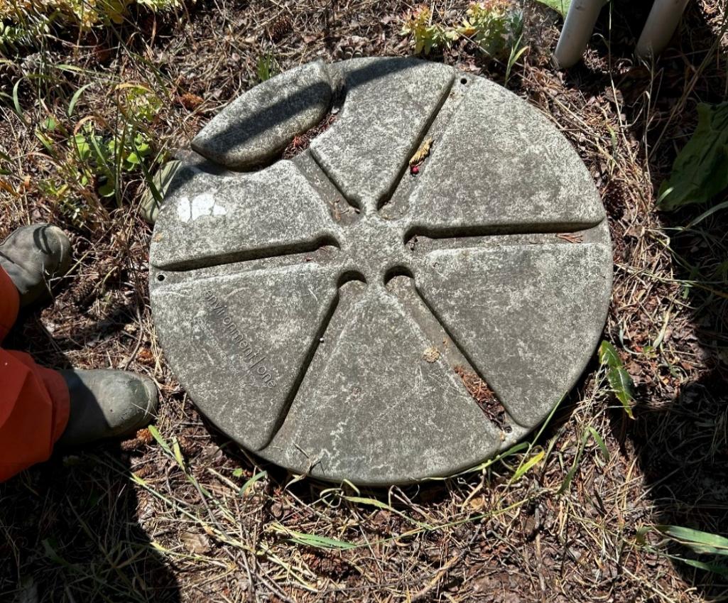
Actual Operating Storage (L): Undetermined Emergency Storage Volume (L)*: Undetermined
*High Water Alarm to sewer inlet pipe Volume (litres) UndeterminedUndetermined-Undetermined**at Maximum Day Flow
Pump #1Pump #2
Pump Discharge Material: Unknown
Voltage: 240V240V Pump Discharge Size (mm): Unknown
11
Power: 1 hp1 hp
Rotational Speed (rpm): 17251725
Make: E-One E-One
Model No.: 2000 Series2000 Series
Impeller Number: UnknownUnknown
Serial Number: E-One DH408298E-One DH408298
Install Year: 20002000
Flow Rate (L/s): 0.70.7 Design
Total Dynamic Head (m): 2828 Design *Bylaw velocities: min. 1 m/s, max. 3.5m/s
Flow Records Information (2022-2024 Data)
Domestic Flow Rate (DFR) (L/cap/day): Undetermined
Pump Capacity (Max. Day Flow):
Average Day Flow (L/s): Undetermined
Maximum Day Flow (L/s) (Existing): 0.23 (Estimated from Modelling)
Maximum Day Flow (L/s) (20 Year): 0.25 (Estimated from Modelling)
Bylaw Flow Estimates
Average Dry Weather Flow - Current (L/s): 0.13 at 350 L/cap/day
Average Dry Weather Flow - Future (L/s): 0.13 at 350 L/cap/day
Pump Cycle Time - Current (2022-2024 Data) at Average Day Flow (min): Undetermined Starts per Hour (per Pump)*: Undetermined at Maximum Day Flow (min): Undetermined Starts per Hour (per Pump)*: Undetermined *Bylaw maximum pump starts - 4 times per hour per pump
Station Supply: 240V
CONTROL
Instrumentation & Controls Phase: 1 PLC: Make and Model Unknown
Transformer Size (kVA): Unknown
Flow Meter: No Main Breaker (A): 16
UPS Power Capacity (VA): 1000
Generator
Model: n/a
Power Rating (kW): n/a
Fuel Source: n/a
Level Control: Unknown
Pressure Transmitter: No
Pressure Gauge: No
SCADA Integration: No
Alarms Functioning: Yes
Measured Current Pulled by Pump Motor
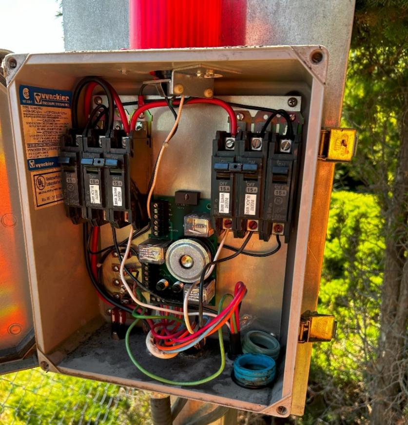
Proximity to Watercourses:
Description of Nearby Watercourse:
Flood of Record Elevation: n/a
Flood Construction Level (FCL): n/a
Lift Station Site Elevation: 559.3
Lift Station Flood Protection Measures: n/a
1. Record drawings, pump curves, photos and flow data were not provided for this lift station. Assessment of items such as emergency storage volumes, domestic flow rates, and pump capacities could not be determined.
2. Lift station located on private property (921 Pinewood Place). City access is from property below (1750 Keloka Drive). Site is behind private fence and surrounded by vegetation.
3. Isolation valves (ball) are located in wet well. Station does not have check valves according to operators. Confined space entry required to operate.
4. Lift station does not have a flow meter and there are no SCADA alarms or trending.
5. Lift station aged (25 years old - 2000) with no major renewal. Operators noted there was an upgrade done in 2015 but details of the upgrade are unknown.
6. Forcemain velocity is only 0.87 m/s and does not meet the City bylaw minimum (1.0 m/s)
7. Site access is very poor, on a slope behind a private fence/gate. Operators can't clean lift station as they can't lift effluent that high with their vac truck.
8. Operators noted there is an opportunity to tie-into the gravity system and decomission this lift station.
9. Lift station has no odour control.
10. Operator identified this lift station as the highest priority for upgrade.
1. A more thorough lift station assessment is recommended as records and data are incomplete.
2. Investigate the feasibility of eliminating this lift station by tying into the gravity system.
3. If eliminating this lift station is not a possibility, a full replacement of the lift station is recommended, relocating the works to a location with better access for operations and maintenance. Replacement to include a new FRP wet well and above ground valve chamber, including a new flow meter.
4. Upgrade aged electrical and controls equipment in conjunction with process mechanical upgrade. Include SCADA alarms.
5. Review additional safety considerations at time of replacement.
6. Odour control may need to be added, to be reviewed at lift station replacement.
7. Install emergency suction line in wet well with lift station replacement.
8. Civil piping will need to be rerouted to the new lift station location. Consider isolation of wet well inflows with knife gate valve in wet well or upstream of lift station.
9. Review need for standby generator and add if needed.
10. Consider increasing pump flow rate on replacement to increase forcemain velocities, so that minimum scouring velocity is met.
Spill Protection Measures: Each pump provides adequate capacity for peak day Asset Type
(a) General Requirements
(b) Civil (Piping, Surface Works, Manhole)
(c) Structural (Building, Wet Well³, Valve Chamber)
(d) Process Mechanical (Pumps, Process Piping, Valves, Odour Control)
(e) Building Mechanical (HVAC, Blower, Hoists, Plumbing, Emergency Eyewash & Shower) n/a (f) Electrical & Controls (Starts / VFDs / Service, Cables and Wiring, Controls, Instrumentation, Lighting)⁴
Notes:
1. Estimated costs are a preliminary Class D estimate in 2025 dollars.
2. Replacement value also includes replacement value of above stated recommendations, assuming those have been or will be implemented at the next lift station upgrade / replacement.
3. For purpose of estimating the lift station's full replacement value, the wet well is included in the replacement value, regardless if it will or will not be replaced at the next upgrade / replacement.
4. Standby generator not included in replacement cost.
Note:
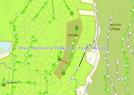
Record drawing not provided.
Pump performance curve not provided.
Year Installed: 2019 (assumed) Site Photo:
Municipal Address: 2139 McDougall Road
Asset Number: LS#16
Catchment Area (ha): 1.5
Service Population: 0 (current) 0 (20 Year Horizon Estimate)
Discharge Manhole: SDM1
Last upgrade: n/a
Other Info:
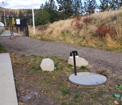
CONFIGURATION
General Configuration: Below ground wet well and valves with duplex submersible pumps
Wet Well Material: Polyethelene
Wet Well Diameter (m): 1.3
Emergency Response Items:
Wet Well Height (m): 2.4 Standby Generator: No
Wet Well Condition: Unknown Pump Bypass Connections: No
Inlet Pipe Material PVC
Components:
VFDs: No
Check Valve: Yes
Isolation Valve: Yes (outside wet well)
Access Hatches: Yes
Generator Connection: Yes
Inlet Pipe Size (mm): 100 Emergency Suction: No Critical Spare Pump: Yes
Ladder: No
Platform: No
Odour Control: No
Ventilation: Yes
Wet Well Photo:Piping and Valving Photo:
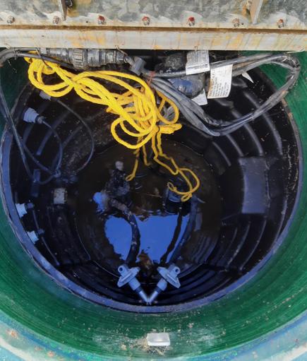
STORAGE CAPACITY Located behind the West Kelowna Multi-Sport Centre. Catchment area has no contributing lift stations.
Pump #1Pump #2
Voltage: 120/240120/240
Phase: 11
Power: 1 hp1 hp
Rotational Speed (rpm): 17251725
Make: EoneEone
Model No.: Extreme Series Grinder Extreme Series Grinder
Header
Pump Discharge Material: HDPE
Pump Discharge Size (mm): 25
Header Material: Stainless Steel
Header Size (mm): 25
Forcemain
Impeller Number: UnknownUnknown Diameter (mm):
Serial Number: S235378S235378 Length (m): 213
Install Year: UnknownUnknown Forcemain Velocity (m/s)*: 0.45
Flow Rate (L/s): 0.880.88 Design Retention Prior to Gravity (mins): 7.9
Total Dynamic Head (m): UnknownUnknown Design *Bylaw velocities: min. 1 m/s, max. 3.5m/s
Flow Records Information (2022-2024 Data)
Domestic Flow Rate (DFR) (L/cap/day): Undetermined
Pump Capacity (Max. Day Flow):
Average Day Flow (L/s): Undetermined
Maximum Day Flow (L/s) (Existing): 0.43 (Estimated from Modelling)
Maximum Day Flow (L/s) (20 Year): 0.43 (Estimated from Modelling)
Bylaw Flow Estimates
Average Dry Weather Flow - Current (L/s): 0.00 at 350 L/cap/day
Average Dry Weather Flow - Future (L/s): 0.00 at 350 L/cap/day
Pump Cycle Time - Current (2022-2024 Data) at Average Day Flow (min): Undetermined Starts per Hour (per Pump)*: Undetermined at Maximum Day Flow (min): Undetermined Starts per Hour (per Pump)*: Undetermined *Bylaw maximum pump starts - 4 times per hour per pump
STATION ELECTRICAL AND CONTROL
Station Supply: 240V
Instrumentation & Controls Phase: 1 PLC: E One Sewer Systems
Transformer Size (kVA): Unknown Flow Meter: No
Main Breaker (A): 50 Level Control: Yes
UPS Power Capacity (VA): 1000
Generator
Pressure Transmitter: No
Pressure Gauge: No
SCADA Integration: No
Model: n/a Alarms Functioning: Yes
Power Rating (kW): n/a
Fuel Source: n/a
No.1No.2
T1 6.15A6.14A Left leg (T1) T2 6.02A6.13A Middle leg (T2) T3 UnknownUnknown Right leg (T3)
Kiosk - Electrical Side Photo:Kiosk - Control Side Photo:
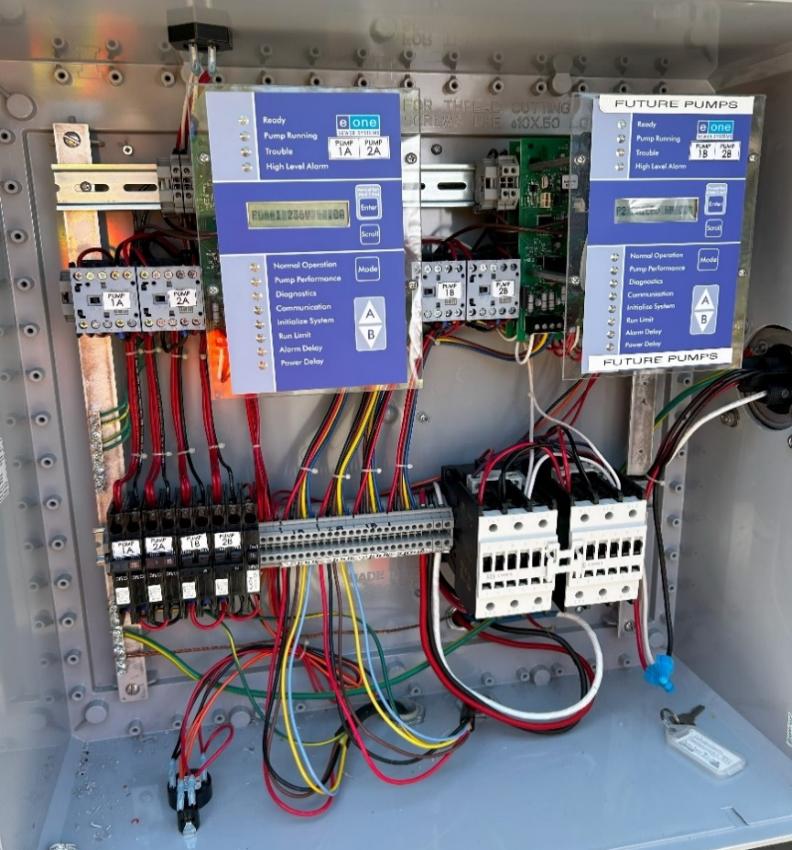
Measured Current Pulled by Pump Motor No photo available
Proximity to Watercourses:
Description of Nearby Watercourse: None
Flood of Record Elevation: n/a
Flood Construction Level (FCL): n/a
Lift Station Site Elevation: 513.48m
Lift Station Flood Protection Measures: n/a
Spill Protection Measures: Each pump provides adequate capacity for peak day
1. Record drawings, pump curves, kiosk photos and flow data were not provided for this lift station. Assessment of items such as emergency storage volumes, domestic flow rates, and pump capacities could not be determined.
2. Lift station located behind the West Kelowna Multi-Sport Centre.
3. According to operators, this station has check valves but no isolation valves. Confined space entry required to enter wet well. 4. Lift station does not have a standby generator and no backup power from Soccer Dome. Operators noted washrooms are closed during power outages.
5. Lift station does not have a flow meter and has no SCADA alarms or trending.
6. Operators noted the lift station was installed approximately 6 years ago (2019).
2. Add flow meter to lift station and connect to SCADA, including alarms.
3. Investigate the need for back-up power and add if needed. Most likely not needed, if washrooms are closed during power outages.
4. As this lift station is fairly new, there are no other upgrades required at this time. However, consider eliminating confined space entry requirements and other potential safety improvements once renewal is due or earlier.
5. Consider installing communcations as other lift stations within the City.
Asset Type
(a) General Requirements
(b) Civil (Piping, Surface Works, Manhole)
(c) Structural (Building, Wet Well³, Valve Chamber)
(d) Process Mechanical (Pumps, Process Piping, Valves, Odour Control)
(e) Building Mechanical (HVAC, Blower, Hoists, Plumbing, Emergency Eyewash & Shower) n/a
(f) Electrical & Controls (Starts / VFDs / Service, Cables and Wiring, Controls, Instrumentation, Lighting)⁴
Notes:
1. Estimated costs are a preliminary Class D estimate in 2025 dollars.
2. Replacement value also includes replacement value of above stated recommendations, assuming those have been or will be implemented at the next lift station upgrade / replacement.
3. For purpose of estimating the lift station's full replacement value, the wet well is included in the replacement value, regardless if it will or will not be replaced at the next upgrade / replacement.
1. A more thorough lift station assessment is recommended as records and data are incomplete. Probability of
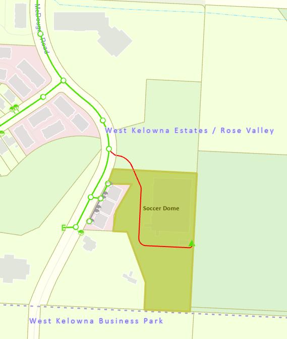
Record drawing not provided.
Pump performance curve not provided.

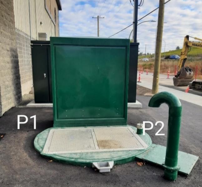
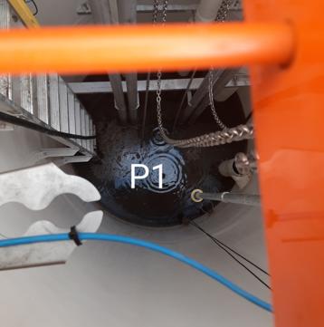
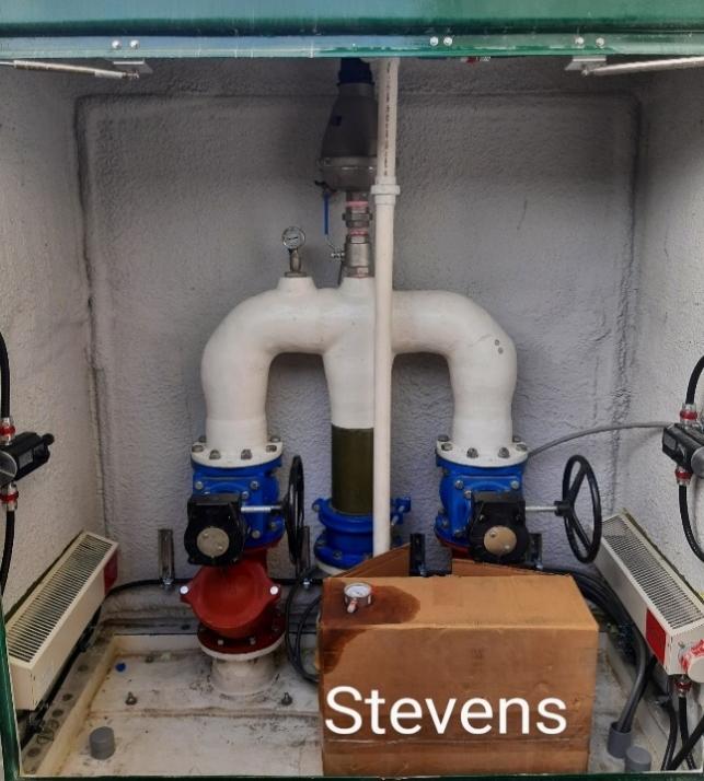
Model No.: N3202HT 466N3202HT 466
Flow Records Information (2022-2024 Data)
Estimates
Pump Cycle Time - Current (2022-2024 Data) at Average Day Flow (min): Undetermined
*Bylaw maximum pump starts - 4 times per hour per pump
Station Supply: 600V Instrumentation & Controls Phase: 3 PLC: Direct Logic 205 D2-09BDC1-1
Transformer Size (kVA): 10
Main Breaker (A): 200 Level Control: Yes (Militronics)
UPS Power Capacity (VA): 700
Pressure Transmitter: Yes (Vegaplus)
Pressure Gauge: Yes Generator
SCADA Integration: Yes
Model: Kohler 150RE0ZJF Alarms Functioning: Yes
Power Rating (kW): 154
Fuel Source: Diesel
Measured Current Pulled by Pump Motor
Right leg (T3) Kiosk - Electrical Side Photo:Kiosk - Control Side Photo:
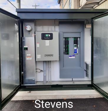
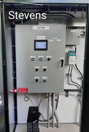
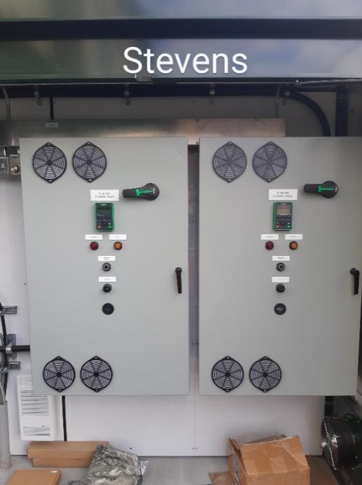
Proximity to Watercourses:
Description of Nearby Watercourse: None
Flood of Record Elevation: n/a
Flood Construction Level (FCL): n/a
Lift Station Site Elevation: 463.55m
Lift Station Flood Protection Measures: n/a
Spill Protection Measures: Each pump provides adequate capacity for peak day
1. Lift station located in an industrial area adjacent to the Tow & Stow Dry Marina building on Stevens Road. Site is fully fenced.
2. Lift station recently upgraded in 2024 with a new FRP wet well, above ground valve and flow meter chamber, and backup generator.
3. The emergency storage is calculated to be 748 L (approx. 1 minute) at maximum day flow. Inadequate for response.
4. The calculated domestic flow rate is unable to be calculated as there is no flow data from after the pumps were replaced (2024).
5. Site access is good with no noted concerns.
1. A more thorough analysis of flows is recommended to determine if the pumps can provide adequate capacity for peak day.
Asset Type
(a) General Requirements
(b) Civil (Piping, Surface Works, Manhole)
(c) Structural (Building, Wet Well³, Valve Chamber)
(d) Process Mechanical (Pumps, Process Piping, Valves, Odour Control)
(e) Building Mechanical (HVAC, Blower, Hoists, Plumbing, Emergency Eyewash & Shower) n/a
(f) Electrical & Controls (Starts / VFDs / Service, Cables and Wiring, Controls, Instrumentation, Lighting, Standby Generator)
Notes:
1. Estimated costs are a preliminary Class D estimate in 2025 dollars.
2. Replacement value also includes replacement value of above stated recommendations, assuming those have been or will be implemented at the next lift station upgrade / replacement.
3. For purpose of estimating the lift station's full replacement value, the wet well is included in the replacement value, regardless if it will or will not be replaced at the next upgrade / replacement.
Note:
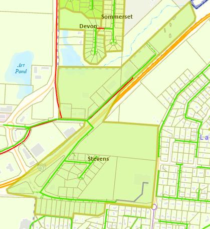
Note: Record drawings for 2023 upgrade were not provided. Issued for Construction drawing shown below (may not match with installed).
Pump performance curve not provided.
Year Installed: 2010
Municipal Address: 2527 Pineridge Place
Asset Number: LS#18
Catchment Area (ha): 3.5
IDENTIFICATION
Site Photo:
Service Population: 298 (current) 340 (20 Year Horizon Estimate)
Discharge Manhole: PRP5
Last upgrade: Unknown
Other Info:
station located in boulevard in Pineridge Place. Catchment area has no contributing lift stations.
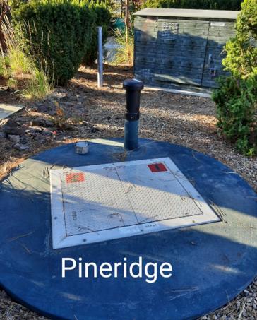
CONFIGURATION
General Configuration: Below ground wet well and valves with duplex submersible pumps
Wet Well Material: FRP
Wet Well Diameter (m): 2.44
Emergency Response Items:
Wet Well Height (m): 6.4 Standby Generator: No
Wet Well Condition: Unknown
Inlet Pipe Material Fiberglass
Pump Bypass Connections: No
Portable Generator Connection: Yes
Inlet Pipe Size (mm): 200 Emergency Suction: Yes Critical Spare Pump: No
Components:
VFDs: No
Check Valve: Yes (75mm Flomatic Swing Check Valve)
Isolation Valve: Yes (75mm Homestead Plug Valve)
Access Hatches: Yes (Aluminum)
Ladder: Yes
Platform: Yes
Odour Control: No
Ventilation: Yes (Gooseneck)
Wet Well Photo:Piping and Valving Photo:
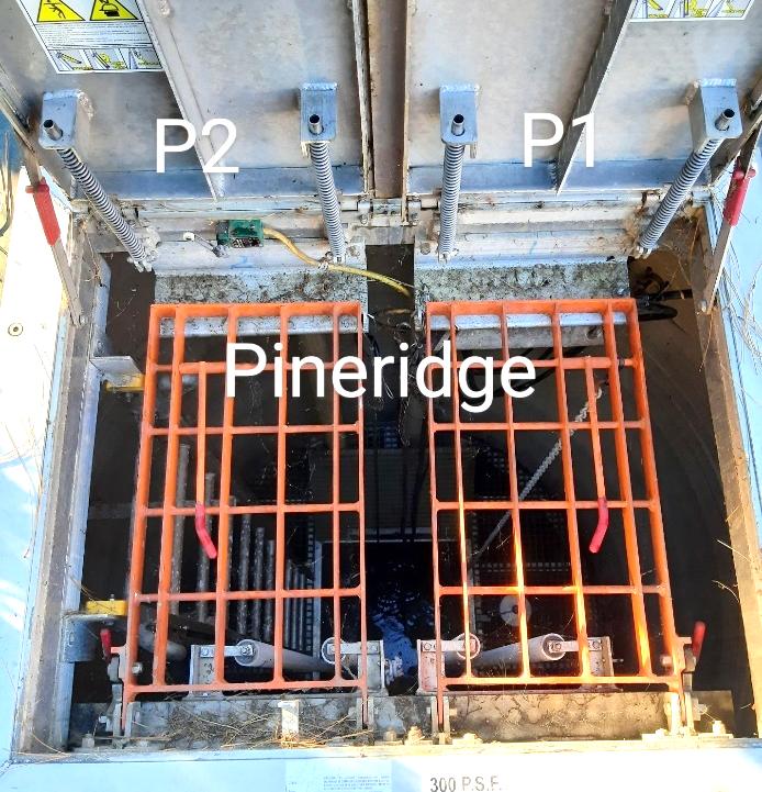
#1Pump #2
240V240V
11
2 hp2 hp
Rotational Speed (rpm): UnknownUnknown
Make: MyersMyers
Model No.: 3VX20M4-21-503VX20M4-21-50
Impeller Number: 9090
Serial Number: 3VX20M4-21-503VX20M4-21-50
Install Year: 20102010
Flow Records Information (2022-2024 Data)
Domestic Flow Rate (DFR) (L/cap/day): Undetermined
Pump Capacity (Max. Day Flow):
Average Day Flow (L/s): Undetermined
Maximum Day Flow (L/s) (Existing): 0.49 (Estimated from Modelling)
Maximum Day Flow (L/s) (20 Year): 0.54 (Estimated from Modelling)
Bylaw Flow Estimates
Average Dry Weather Flow - Current (L/s): 1.21 at 350 L/cap/day
Average Dry Weather Flow - Future (L/s): 1.38 at 350 L/cap/day
Pump Cycle Time - Current (2022-2024 Data)
at Average Day Flow (min): Undetermined Starts per Hour (per Pump)*: Undetermined at Maximum Day Flow (min): 53.27 Starts per Hour (per Pump)*: 0.6 *Bylaw maximum pump starts - 4 times per hour per pump
Station Supply: 240V
ELECTRICAL AND CONTROL
Instrumentation & Controls Phase: 1
Direct Logic 06 D0-06DR
Transformer Size (kVA): Unknown Flow Meter: Yes (75mm Siemens Flow Meter)
Main Breaker (A): 100 Level Control: Yes (Float Switch)
UPS Power Capacity (VA): 1000
Generator
Model: n/a
Power Rating (kW): n/a
Fuel Source: n/a
Pressure Transmitter: Unknown
Pressure Gauge: Yes
SCADA Integration: Yes
Alarms Functioning: Yes
Measured Current Pulled by Pump Motor
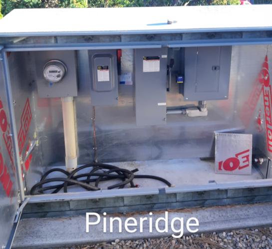
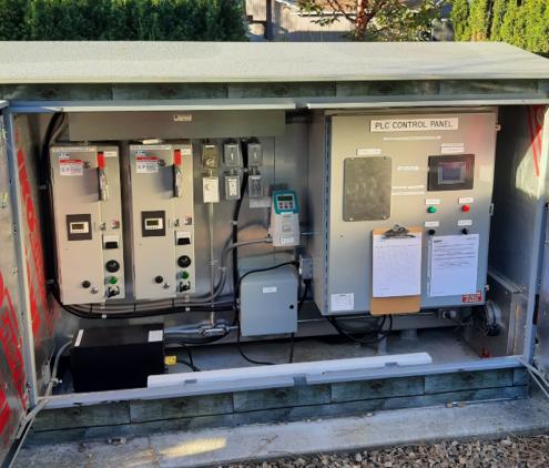
Proximity to Watercourses:
Description of Nearby Watercourse: None
Flood of Record Elevation: n/a
Flood Construction Level (FCL): n/a
Lift Station Site Elevation: 429.4m
Lift Station Flood Protection Measures: n/a
Spill Protection Measures: Each pump provides adequate capacity for peak day
1. Recent flow data for this lift station was not provided. The design flow provided by the City is 4.7 L/s but an HMI image shows the flow meter reading 6.1 L/s.
2. Lift station located in landscaped boulevard in the middle of Pineridge Place. Site is surrounded by vegetation.
3. Valves (plug and check) are located in wet well. Confined space entry required to operate.
4. Lift station does not have a standby generator, but has a manual transfer switch. Emergency storage is calculated to be 140L (approx. 4 minutes) at maximum day flow. Inadequate for response.
5. Lift station is 15 years old (2010) with no major renewal. Operators noted this is a good station with no concerns.
6. Pump curve shows overall efficiency is approx. 27%, operating very close to the best efficiency point.
7. Site access is good with adjacent parking/access for operations and maintenance.
8. Lift station has no odour control.
9. Lift station has no critical spare pump.
10. Operators noted that work for a generator transfer switch has started.
1. A more thorough review of lift station flows is recommended as data is incomplete.
2. Assess condition of mechanical process equipment (pumps, piping, and valves) in about 5 years and determine remaining life expectancy. If replacement is required, valves to be added to above ground chamber (Barski). An earlier upgrade could be explored to eliminate the confined space entry requirements.
3. Review pump selection at time of renewal to select a pump with improved efficiency.
4. Upgrade electrical and controls equipment in conjunction with process mechanical upgrade.
5. Add standby generator to lift station with electrical equipment upgrades, including automatic transfer switch. Procure critical spare pump.
6. Complete testing of existing wet well at time of process mechanical equipment assessment to confirm condition (can be provided by Barski). If found in acceptable condition, wet well can remain.
7. Review additional safety considerations at time of replacement.
8. Review odour control requirements at time of above ground valve chamber upgrade.
9. Install bypass connection on forcemain for emergencies.
10. Civil piping can be maintained. Consider isolation of wet well inflows with knife gate valve in wet well or upstream of lift station.
Asset Type
(a) General Requirements
(b) Civil (Piping, Surface Works, Manhole)
(c) Structural (Building, Wet Well³, Valve Chamber)
(d) Process Mechanical (Pumps, Process Piping, Valves, Odour Control)
(e) Building Mechanical (HVAC, Blower, Hoists, Plumbing, Emergency Eyewash & Shower) n/a (f) Electrical & Controls (Starts / VFDs / Service, Cables and Wiring, Controls, Instrumentation, Lighting)⁴
Notes:
1. Estimated costs are a preliminary Class D estimate in 2025 dollars.
2. Replacement value also includes replacement value of above stated recommendations, assuming those have been or will be implemented at the next lift station upgrade / replacement.
3. For purpose of estimating the lift station's full replacement value, the wet well is included in the replacement value, regardless if it will or will not be replaced at the next upgrade / replacement.
Note:
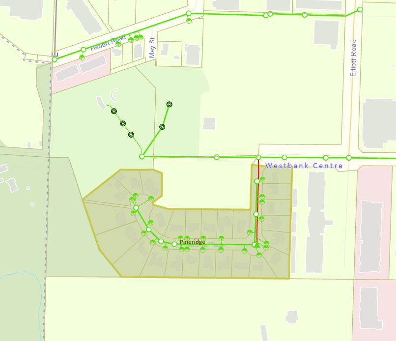
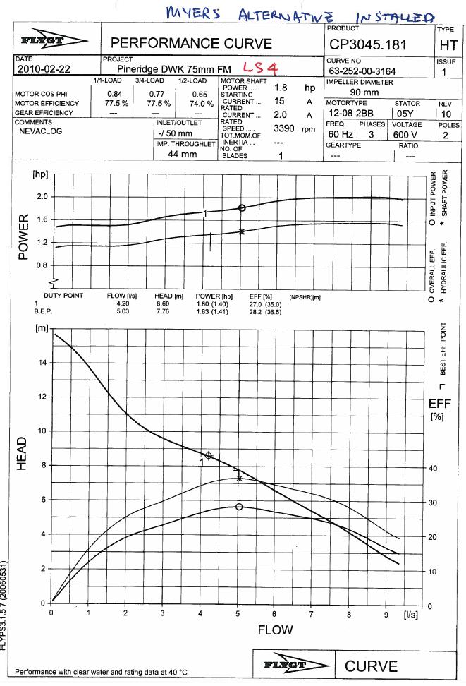
Year Installed: 2011
Municipal Address: 2856 Inverness Road
Asset Number: LS#19
Catchment Area (ha): 6.1
Service Population: 162 (current)
Site Photo:
232 (20 Year Horizon Estimate)
Discharge Manhole: 2GT25
Last upgrade: 2021
Other Info:
Located in a landscaped boulevard beside Inverness Road. Catchment area has no contributing lift stations.
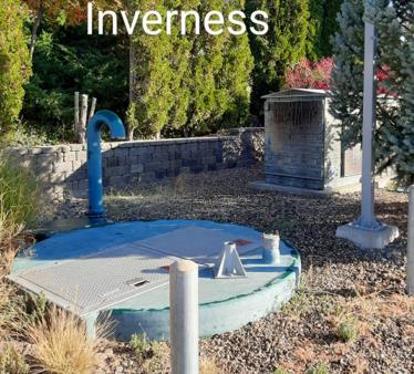
General Configuration: Below ground wet well and valves with duplex submersible pumps
Wet Well Material: FRP
Wet Well Diameter (m): 2.44
Wet Well Height (m): 5.69
Wet Well Condition: Unknown
Inlet Pipe Material PVC
Inlet Pipe Size (mm): 200
Components:
VFDs: No
Check Valve: Yes (100mm HDL Ball Check Valve)
Isolation Valve: Yes (100mm Valmatic Plug Valve)
Access Hatches: Yes (MSU)
Emergency Response Items:
Standby Generator: No
Pump Bypass Connections: No
Portable Generator Connection: Yes (600V)
Emergency Suction: Yes Critical Spare Pump: No
Ladder: Yes (Aluminum)
Platform: Yes (Aluminum/FRP)
Odour Control: Yes (Carbon)
Ventilation: Yes (Gooseneck)
Wet Well Photo:Piping and Valving Photo:
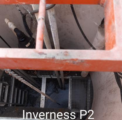
HYDRAULIC STORAGE CAPACITY
Actual Operating Storage (L): Undetermined
Emergency Storage Volume (L)*: Undetermined LeadLagPumps OffHWL AlarmLWL Alarm
Emergency Storage Time - Current (mins)**: Undetermined Setpoints (%) 6070356515
Emergency Storage Time - Future (mins)**: Undetermined Setpoint Depth (m) UndeterminedUndeterminedUndeterminedUndeterminedUndetermined *High Water Alarm to sewer inlet pipe Volume (litres) UndeterminedUndetermined-Undetermined**at Maximum Day Flow
Pump #1Pump #2
600V600V
33
Power: 3 hp3 hp
Rotational Speed (rpm): 16951695
Make: FlygtFlygt
Model No.: NP3085MTNP3085MT
Impeller Number: 135135
Serial Number: 3085.160-11508993085.160.1150898
Install Year: 20112011
(m): 5.95.9
Flow Records Information (2022-2024 Data)
Domestic Flow Rate (DFR) (L/cap/day): Undetermined
Pump Capacity (Max. Day Flow):
Average Day Flow (L/s): Undetermined
Maximum Day Flow (L/s) (Existing): 1.15 (Estimated from Modelling)
Maximum Day Flow (L/s) (20 Year): 1.48 (Estimated from Modelling)
Bylaw Flow Estimates
Average Dry Weather Flow - Current (L/s): 0.66 at 350 L/cap/day
Average Dry Weather Flow - Future (L/s): 0.94 at 350 L/cap/day
Pump Cycle Time - Current (2022-2024 Data)
at Average Day Flow (min): Undetermined Starts per Hour (per Pump)*: Undetermined at Maximum Day Flow (min): Undetermined Starts per Hour (per Pump)*: Undetermined *Bylaw maximum pump starts - 4 times per hour per pump
Station Supply: 600V
STATION ELECTRICAL AND CONTROL
Instrumentation & Controls
Phase: 3 PLC:
Direct Logic 06 D0-06DR
Transformer Size (kVA): 10 Flow Meter: Yes (100 mm Siemens Flow Meter)
Main Breaker (A): 100
Level Control: Yes (Bulbs) UPS Power Capacity (VA): 1000
Generator
Model: n/a
Power Rating (kW): n/a
Fuel Source: n/a
Pressure Transmitter: No
Pressure Gauge: Yes
SCADA Integration: Yes
Alarms Functioning: Yes
Measured Current Pulled by Pump Motor
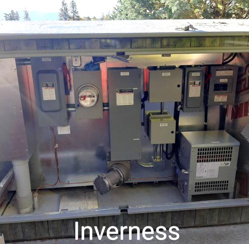
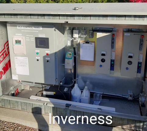
Proximity to Watercourses:
Description of Nearby Watercourse:
Tributary to Powers Creek
Flood of Record Elevation: Unknown
Flood Construction Level (FCL): Unknown
Lift Station Site Elevation: 488.85m
Lift Station Flood Protection Measures: Unknown
Spill Protection Measures: Each pump provides adequate capacity for peak day
1. Flow data and setpoints were not provided for this lift station. Assessment of items such as emergency storage volumes, domestic flow rates, and pump capacities could not be determined.
2. Lift station located in landscaped boulevard beside Inverness Road. Site is adjacent to low landscape retaining wall.
3. Lift station is located approx. 20m from a tributary stream to Powers Creek. Creek flood elevations are unknown, but City GIS shows the lift station and creek within 2m elevation difference.
4. Valves (plug and check) are located in wet well. Confined space entry required to operate.
5. Lift station does not have a standby generator or odour control.
6. Lift station has a flow meter.
7. Lift station is 14 years old (2011) with no major renewal. Pumps were rebuilt in 2018. Operators noted this is a good station.
8. Pump curve shows overall efficiency is approx. 33%, operating far from its' efficiency point.
9. Site access is good with no issues noted.
10. System improvements in 2021 greatly reduced the catchment area and inflows to the Inverness lift station. This work included decomissioning Glengary lift station (which previously flowed into Inverness) and redirecting these flows, as well as a large portion of the Inverness catchment, into a newly constructed gravity sewer nearby.
11. Lift station has no critical spare pump.
1. A more thorough review of lift station flows is recommended as data is incomplete.
2. Assess condition of mechanical process equipment (pumps, piping, and valves) in about 6 years and determine remaining life expectancy. If replacement is required, valves to be added to above ground chamber (Barski). An earlier upgrade could be explored to eliminate the confined space entry requirements.
3. Review pump selection at time of renewal to select a pump that is better suited for the system and operates near its BEP to increase pump efficiency.
4. Upgrade electrical and controls equipment in conjunction with process mechanical upgrade.
5. Add standby generator to lift station with electrical equipment upgrades, including automatic transfer switch. Procure critical spare pump.
6. Complete testing of existing wet well at time of mechanical process equipment assessment to confirm condition (can be provided by Barski). If found in acceptable condition, wet well can remain.
7. Review additional safety considerations at time of replacement.
8. Review odour control requirements at time of above ground valve chamber upgrade.
9. Install bypass connection on forcemain for emergencies.
10. Civil piping can be maintained. Consider isolation of wet well inflows with knife gate valve in wet well or upstream of lift station.
11. Review flood risk of lift station due to potential high flows from tributary to Powers Creek. Review emergency procedures for high creek levels and ensure there is a plan to prevent flooding of the lift station (i.e. sandbagging, tiger dam, etc.) if at risk.
Asset Type
(a) General Requirements
(b) Civil (Piping, Surface Works, Manhole)
(c) Structural (Building, Wet Well³, Valve Chamber)
(d) Process Mechanical (Pumps, Process Piping, Valves, Odour Control)
(e) Building Mechanical (HVAC, Blower, Hoists, Plumbing, Emergency Eyewash & Shower) n/a (f) Electrical & Controls (Starts / VFDs / Service, Cables and Wiring, Controls, Instrumentation, Lighting, Standby Generator)
Notes:
1. Estimated costs are a preliminary Class D estimate in 2025 dollars.
2. Replacement value also includes replacement value of above stated recommendations, assuming those have been or will be implemented at the next lift station upgrade / replacement.
3. For purpose of estimating the lift station's full replacement value, the wet well is included in the replacement value, regardless if it will or will not be replaced at the next upgrade / replacement.
Note:
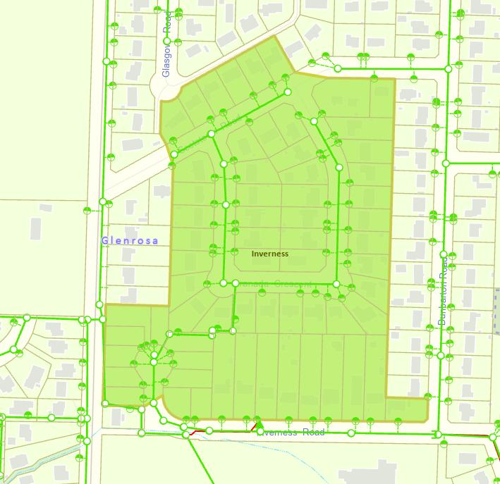
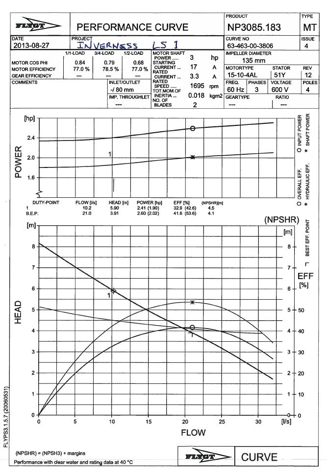
Year Installed: 2012
Municipal Address: 2415 Hayman Road
Asset Number: LS#20
Catchment Area (ha): 18.0
IDENTIFICATION
Site Photo:
Service Population: 45 (current) 69 (20 Year Horizon Estimate)
Discharge Manhole: LV283
Last upgrade: Unknown
Other Info:
Located adjacent to Issler Park on Hayman Road. Catchment area has no contributing lift stations.
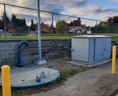
CONFIGURATION
General Configuration: Below ground wet well and valves with duplex submersible pumps
Wet Well Material: FRP
Wet Well Diameter (m): Unknown
Emergency Response Items:
Wet Well Height (m): Unknown Standby Generator: No
Wet Well Condition: Unknown Pump Bypass Connections: No
Inlet Pipe Material PVC
Inlet Pipe Size (mm): 200
Components:
VFDs: No
Check Valve: Yes (80mm HDL Ball Check Valve)
Isolation Valve: Yes (80mm Keystone Plug Valve)
Access Hatches: Yes
Portable Generator Connection: Yes (240V)
Emergency Suction: Yes Critical Spare Pump: Yes
Ladder: Yes
Platform: Yes
Odour Control: No
Ventilation: Yes
Wet Well Photo:Piping and Valving Photo:
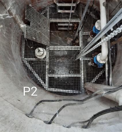
HYDRAULIC STORAGE CAPACITY
Actual Operating Storage (L): Undetermined
Emergency Storage Volume (L)*: Undetermined LeadLagPumps OffHWL AlarmLWL Alarm
Emergency Storage Time - Current (mins)**: Undetermined Setpoints (%) 7080408510
Emergency Storage Time - Future (mins)**: Undetermined Setpoint Depth (m) UndeterminedUndeterminedUndeterminedUndeterminedUndetermined *High Water Alarm to sewer inlet pipe Volume (litres) UndeterminedUndetermined-Undetermined**at Maximum Day Flow
Speed (rpm): 33253325
Make: FlygtFlygt
Model No.: CP3057.181CP3057.181
Impeller Number:
Flow Records Information (2022-2024 Data) Pump Capacity (Max. Day Flow):
Domestic Flow Rate (DFR) (L/cap/day): Undetermined
Average Day Flow (L/s): Undetermined Maximum Day Flow (L/s) (Existing): 1.20 (Estimated from Modelling) Maximum Day Flow (L/s) (20 Year): 1.34 (Estimated from Modelling)
Bylaw Flow Estimates
Average Dry Weather Flow - Current (L/s): 0.18 at 350 L/cap/day
Average Dry Weather Flow - Future (L/s): 0.28 at 350 L/cap/day
Pump Cycle Time - Current (2022-2024 Data)
at Average Day Flow (min): Undetermined Starts per Hour (per Pump)*: Undetermined at Maximum Day Flow (min): Undetermined Starts per Hour (per Pump)*: Undetermined *Bylaw maximum pump starts - 4 times per hour per pump
Station Supply: 230V
Instrumentation & Controls Phase: 1 PLC: Direct Logic 06 D0-06DR
Transformer Size (kVA): Unknown Flow Meter: Yes (Siemens Flow Meter) Main Breaker (A): 100 Level Control: Yes (Milltronics/Bulb Backup)
UPS Power Capacity (VA): 1000
Generator
Model: n/a
Power Rating (kW): n/a
Fuel Source: n/a
Pressure Transmitter: No
Pressure Gauge: Yes
SCADA Integration: Yes
Alarms Functioning: Yes
Measured Current Pulled by Pump Motor
Left leg (T1)
Middle leg (T2)
Right leg (T3)
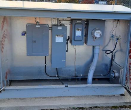
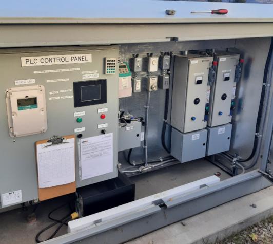
Proximity to Watercourses:
Description of Nearby Watercourse: None
Flood of Record Elevation: n/a
Flood Construction Level (FCL): n/a
Lift Station Site Elevation: ~488 m
Lift Station Flood Protection Measures: n/a
Spill Protection Measures: Each pump provides adequate capacity for peak day
1. Recent flow data, setpoints and record drawings were not provided for this lift station. Assessment of items such as emergency storage volumes, domestic flow rates, and pump capacities could not be determined.
2. Lift station located adjacent to Issler Park off of Hayman Road. Site is beside retaining wall on the gravel shoulder.
3. Valves (plug and check) are located in wet well. Confined space entry required to operate.
4. Lift station does not have a standby generator or odour control.
5. Lift station has a flow meter.
6. Lift station is 13 years old (2012) with no major renewal. Pumps were replaced in 2018. Operators did not note any requested upgrades.
7. Pump curve shows overall efficiency is approx. 48%, operating close to the best efficiency point.
8. Site access is good.
1. A more thorough review of lift station records and data is recommended as records and data are incomplete.
2. Assess condition of mechanical process equipment (pumps, piping, and valves) in about 7 years and determine remaining life expectancy. If replacement is required, valves to be added to above ground chamber (Barski). An earlier upgrade could be explored to eliminate the confined space entry requirements.
3. Review pump selection at time of renewal to select a pump that is better suited for the system and operates near its BEP to increase pump efficiency.
4. Upgrade electrical and controls equipment in conjunction with process mechanical upgrade.
5. Complete testing of existing wet well at time of mechanical process equipment assessment to confirm condition (can be provided by Barski). If found in acceptable condition, wet well can remain.
6. Review odour control requirements at time of above ground valve chamber upgrade.
7. Review additional safety considerations at time of replacement.
8. Install bypass connection on forcemain for emergencies.
9. Civil piping can be maintained. Consider isolation of wet well inflows with knife gate valve in wet well or upstream of lift station.
10. Review need for standby generator and add if needed with a transfer switch.
Asset Type
(a) General Requirements
(b) Civil (Piping, Surface Works, Manhole)
(c) Structural (Building, Wet Well³, Valve Chamber)
(d) Process Mechanical (Pumps, Process Piping, Valves, Odour Control)
(e) Building Mechanical (HVAC, Blower, Hoists, Plumbing, Emergency Eyewash & Shower) n/a (f) Electrical & Controls (Starts / VFDs / Service, Cables and Wiring, Controls, Instrumentation, Lighting)⁴
Notes:
1. Estimated costs are a preliminary Class D estimate in 2025 dollars.
2. Replacement value also includes replacement value of above stated recommendations, assuming those have been or will be implemented at the next lift station upgrade / replacement.
3. For purpose of estimating the lift station's full replacement value, the wet well is included in the replacement value, regardless if it will or will not be replaced at the next upgrade / replacement.
4. Standby generator not included in replacement cost.
Note:
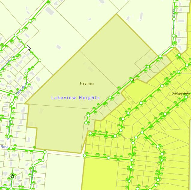
Record drawing not provided.
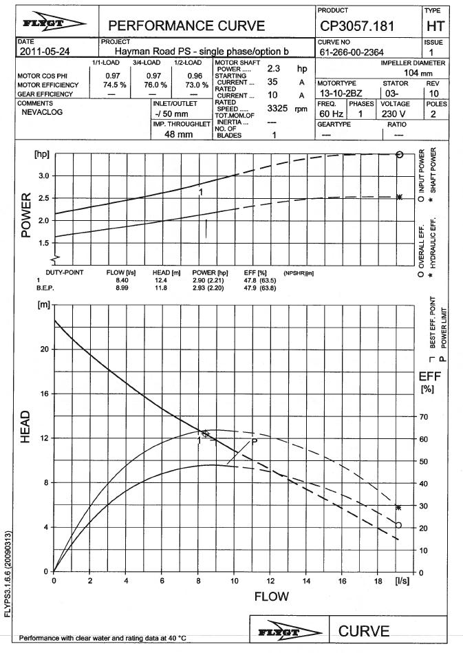
Year Installed: 2012
Municipal Address: 2252 Bridgeview Road
Asset Number: LS#21
Catchment Area (ha): 46.6
Service Population: 665 (current) 1,166 (20 Year Horizon Estimate)
Discharge Manhole: LV277B
Last upgrade: Unknown
Other Info:
adjacent to Bridgeview Road. Catchment area has no contributing lift stations.
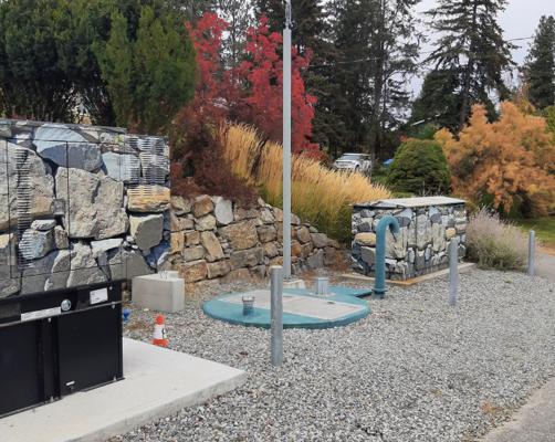
CONFIGURATION
General Configuration: Below ground wet well and valves with duplex submersible pumps
Components:
VFDs: No Ladder: Yes
Check Valve: Yes (100mm HDL Ball Check Valve)
Isolation Valve: Yes (100mm Keystone Plug)
Odour Control: Yes
Access Hatches: Yes Ventilation: Yes Wet Well Photo:Piping and Valving Photo:
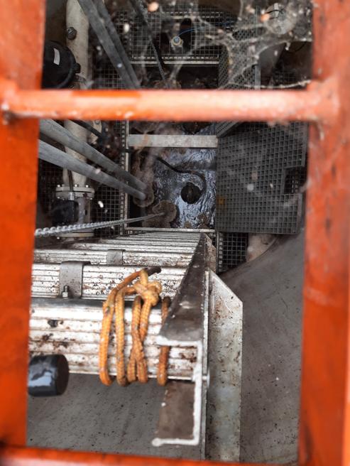
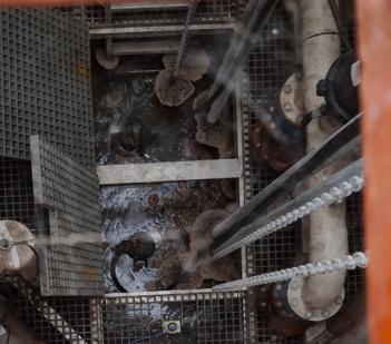
Flow Records Information (2022-2024 Data) Pump Capacity (Max. Day Flow):
Domestic Flow Rate (DFR) (L/cap/day): Undetermined Average Day Flow (L/s): Undetermined Maximum Day Flow (L/s) (Existing):
Bylaw Flow Estimates
Average Dry Weather Flow - Current (L/s): 2.69 at 350 L/cap/day
Modelling)
Average Dry Weather Flow - Future (L/s): 4.72 at 350 L/cap/day
Pump Cycle Time - Current (2022-2024 Data)
at Average Day Flow (min): Undetermined Starts per Hour (per Pump)*: Undetermined at Maximum Day Flow (min): Undetermined Starts per Hour (per Pump)*: Undetermined *Bylaw maximum pump starts - 4 times per hour per pump
Station Supply: 230V
Instrumentation & Controls Phase: 3 PLC: Direct Logic 06 D0-06DR
Transformer Size (kVA): Unknown
Meter: Yes Main Breaker (A): 200 Level Control: Yes
UPS Power Capacity (VA): 1000
Generator
Model: Generac SD80
Power Rating (kW): 80
Fuel Source: Diesel
Pressure Transmitter: No
Pressure Gauge: Yes
SCADA Integration: Yes
Alarms Functioning: Yes
AND CONTROL Measured Current Pulled by Pump Motor
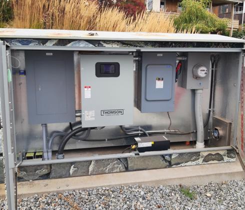
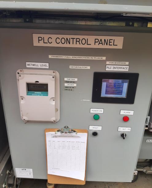
Proximity to Watercourses:
Description of Nearby Watercourse: None
Flood of Record Elevation: n/a
Flood Construction Level (FCL): n/a
Lift Station Site Elevation: ~471.80
Lift Station Flood Protection Measures: n/a
Spill Protection Measures: Each pump provides adequate capacity for peak day
1. Recent flow data, setpoints and record drawings were not provided for this lift station. Assessment of items such as emergency storage volumes, domestic flow rates, and pump capacities could not be determined.
2. Lift station located adjacent to Bridgeview Road in a residential area. Site is adjacent to a landscape retaining wall on the gravel shoulder.
3. Valves (plug and check) are located in wet well. Confined space entry required to operate.
4. Lift station has a standby generator, installed about two years ago according to operators.
5. Lift station has a flow meter.
6. Lift station is 13 years old (2012) with no major renewal.
7. Pump curve shows overall efficiency is approx. 39%, operating far from its' the best efficiency point.
8. Operator noted that lift station needs above ground valving (within 10 years).
9. Site access is good.
1. A more thorough review of lift station flow records, drawings and data is recommended as assessment is incomplete.
2. Assess condition of mechanical process equipment (pumps, piping, and valves) in about 7 years and determine remaining life expectancy. If replacement is required, valves to be added to above ground chamber (Barski). An earlier upgrade could be explored to eliminate the confined space entry requirements.
3. Review pump selection at time of renewal to select a pump that is better suited for the system and operates near its BEP to increase pump efficiency.
4. Upgrade aged electrical and controls equipment in conjunction with process mechanical upgrade.
5. Complete testing of existing wet well at time of mechanical process equipment assessment to confirm condition (can be provided by Barski). If found in acceptable condition, wet well can remain.
6. Review additional safety considerations at time of replacement.
7. Install bypass connection on forcemain for emergencies.
8. Civil piping can be maintained. Consider isolation of wet well inflows with knife gate valve in wet well or upstream of lift station.
Asset Type
(a) General Requirements
(b) Civil (Piping, Surface Works, Manhole)
(c) Structural (Building, Wet Well³, Valve Chamber)
(d) Process Mechanical (Pumps, Process Piping, Valves, Odour Control)
(e) Building Mechanical (HVAC, Blower, Hoists, Plumbing, Emergency Eyewash & Shower) n/a (f) Electrical & Controls (Starts / VFDs / Service, Cables and Wiring, Controls, Instrumentation, Lighting, Standby Generator)
Notes:
1. Estimated costs are a preliminary Class D estimate in 2025 dollars.
2. Replacement value also includes replacement value of above stated recommendations, assuming those have been or will be implemented at the next lift station upgrade / replacement.
3. For purpose of estimating the lift station's full replacement value, the wet well is included in the replacement value, regardless if it will or will not be replaced at the next upgrade / replacement.
Note:
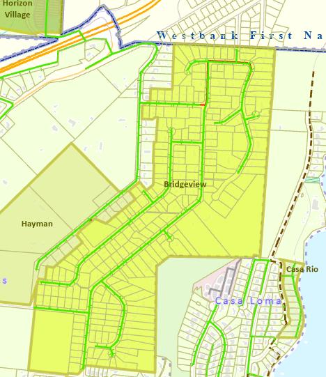
Record drawing not provided.
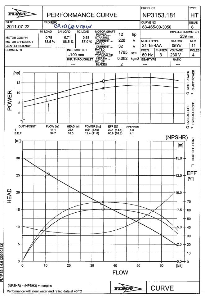

Year Installed: 1999
Municipal Address: 2210 Horizon Drive
Asset Number: LS#22
Catchment Area (ha): 143.0
Photo:
Service Population: 2,154 (current) 2,508 (20 Year Horizon Estimate)
Discharge Manhole: WH29
Last upgrade: 2015
Other Info:
General Configuration:
Wet Well Material: FRP
Wet Well Diameter (m): 3.05
Components:
VFDs: Yes
Check Valve: Yes (150mm Ball Check Valve)
Isolation Valve: Yes (150mm Eccentric Plug Valve)
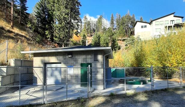
Emergency Response Items:
Ladder: Yes (Aluminum)
Platform: Yes (FRP Grating)
Odour Control: Yes (Carbon Filter)
Access Hatches: Yes Ventilation: Yes Wet Well Photo:Piping and Valving Photo:
#1Pump #2
600600
33
72 hp72 hp
Rotational Speed (rpm): 35553555
Make: FlygtFlygt
Model No.: FP3202SHFP3202SH
Impeller Number: 273273
Serial Number: 3202.095-16500053202.095-1650006
Total Dynamic Head (m): UnknownUnknown
Flow Records Information (2022-2024 Data)
Domestic Flow Rate (DFR) (L/cap/day): Undetermined
Average Day Flow (L/s): Undetermined Maximum Day Flow (L/s) (Existing): 23.88 (Estimated from Modelling) Maximum Day Flow (L/s) (20 Year): 28.73 (Estimated from Modelling)
Bylaw Flow Estimates
Average Dry Weather Flow - Current (L/s): 8.73 at 350 L/cap/day
Average Dry Weather Flow - Future (L/s): 10.16 at 350 L/cap/day
Pump Cycle Time - Current (2022-2024 Data) at Average Day Flow (min): Undetermined
*Bylaw maximum pump starts - 4 times per hour per pump
Station Supply: 600V
Instrumentation & Controls Phase: 3 PLC: HF040432
Transformer Size (kVA): 30 Flow Meter: Yes
Main Breaker (A): 200 Level Control: Yes
UPS Power Capacity (VA): 1500 Pressure Transmitter: No Pressure Gauge: No
Generator
SCADA Integration: Yes
Model: Kohler 200REOZJF Alarms Functioning: Yes
Power Rating (kW): 200
Fuel Source: Diesel
ELECTRICAL AND CONTROL Measured Current Pulled by Pump Motor
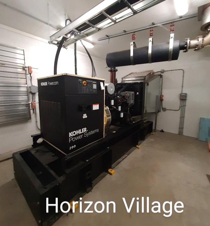
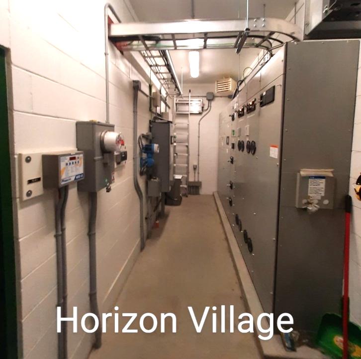
Proximity to Watercourses:
Description of Nearby Watercourse: None
Flood of Record Elevation: n/a
Flood Construction Level (FCL): n/a
Lift Station Site Elevation: 412.7m
Lift Station Flood Protection Measures: n/a
Spill Protection Measures: Each pump does not provide adequate capacity for peak day
Data was taken from tender drawings as no record drawings were available. Actual conditions may differ.
1. Data for setpoints and flow data was not provided for this lift station. Data taken from HMI image.
and controls
3. Other lift stations contribute to this catchment. Failure of this lift station would impact a much larger area.
4. Pump flow rate is unknown as no pump curve was provided. Flow rate was assumed based on historical max flow rate given on HMI image. Actual pump capacity may differ as the pumps are controlled by VFDs (may be more if max flow rate not achieved on VFD or could be less if max flow rate is with 2 pump operating simultaneously). Firm capacity is met based on assumption, but actual could differ.
5. Isolation and check valves are located in wet well, confined space entry required to access/maintain. 6. Lift station has a standby generator, located in the utility building.
7. Additional storage is provided by the old concrete wet well and additional storage chamber adjacent to old wet well.
8. Lift station has 9,644L of emergency storage (approx. 6 minute) at maximum day flow (assuming old wet well is being utilized as emergency storage and old pumps have been removed from old wet well). Inadequate for response.
9. Lift station has flow meter, located in a manhole chamber. Confined space entry required to access/maintain. 10. Operators noted site access is good.
1. Obtain pump curve. Confirm firm pump capacity via wet well drawdown test. Update findings in this data sheet and upgrade pumps / add third pump as needed to meet current and future peak flows.
2. Add valves to above ground valve chamber at next upgrade to eliminate confined space entry. Process mechanical equipment (pumps, piping, and valves) are 11 years old and expected to be in good condition, so an immediate upgrade not required.
3. Add flow meter to above ground valve chamber at next process mechanical upgrade to eliminate confined space entry.
4. Upgrade electrical and controls equipment in conjunction with process mechanical upgrade.
5. Complete testing of wet well at next upgrade to confirm condition (can be provided by Barski). Currently expected to be in good condition. If found in acceptable condition, wet well can remain.
6. Review additional safety considerations at time of replacement.
7. Confirm if wye with gate valves were installed on forcemain and if it can be used as a bypass connection for the forcemain during emergencies.
8. Civil piping can be maintained. Consider isolation of wet well inflows with knife gate valve in wet well or upstream of lift station.
Asset Type
(a) General Requirements
(b) Civil (Piping, Surface Works, Manhole)
(c) Structural (Building, Wet Well ³, Valve Chamber)
(d) Process Mechanical (Pumps, Process Piping, Valves, Odour Control)
(e) Building Mechanical (HVAC, Blower, Hoists, Plumbing, Emergency Eyewash & Shower)
(f) Electrical & Controls (Starts / VFDs / Service, Cables and Wiring, Controls, Instrumentation, Lighting, Standby Generator)
Notes:
1. Estimated costs are a preliminary Class D estimate in 2025 dollars.
2. Replacement value also includes replacement value of above stated recommendations, assuming those have been or will be implemented at the next lift station upgrade / replacement.
3. For purpose of estimating the lift station's full replacement value, the wet well is included in the replacement value, regardless if it will or will not be replaced at the next upgrade / replacement.
Note:
The condition assessment findings are based on background information, documentation, photos, and record drawings provided by the City, and discussions with City operators. No site visits were completed to physically assess the condition of the lift stations. As such, the quality of condition assessment findings is dependent on the quality of data provided to McElhanney, and may not fully represent site conditions.
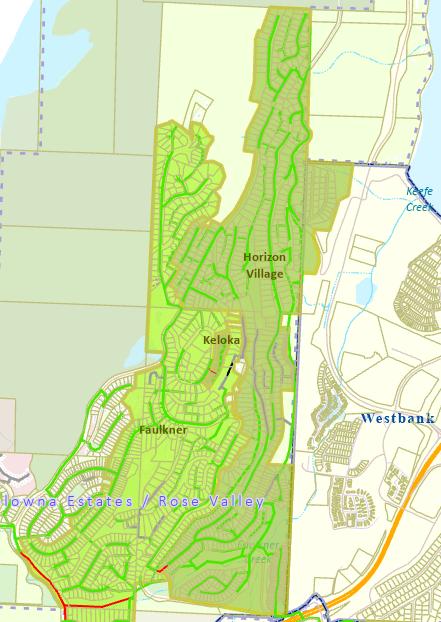
Pump performance curve not provided.
Year Installed: 1997
Municipal Address: Closest to 2160 Horizon Drive
Asset Number: LS#23
Catchment Area (ha): 97.6
Service Population: 2,077 (current) 2,175 (20 Year Horizon Estimate)
Discharge Manhole: 3EBCONN3EB14
Last upgrade: 2013
Other Info:
General Configuration:
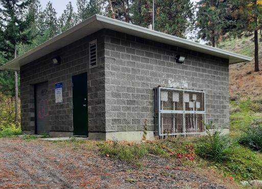
CONFIGURATION
Below ground wet well and valves with duplex submersible pumps (with space for a third pump). Controls and generator located inside building. Located down a gravel access driveway from Horizon Drive. Contributing lift stations include Horizon Village, Hayman, Bridgeview, Somerset, Devon Court, and Keloka Lift Stations. Total catchment area with contributing catchments = 312.7 ha.
Components:
VFDs: Yes
Check Valve: Yes (200mm Ball Check Valve)
Isolation Valve: Yes (200mm Eccentric Plug Valve)
Ladder: Yes (Aluminum)
Platform: Yes (FRP Grating)
Odour Control: Yes (Carbon Filter)
Access Hatches: Yes Ventilation: Yes Wet Well Photo:Piping and Valving Photo:
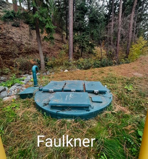
photo
Speed (rpm): 36003600
Make: FlygtFlygt
Model No.: FP3202SHFP3202SH
Impeller Number: 273273
Serial Number: 3202.095-13800113202.095-1380012
(m): 112112
Flow Records Information (2022-2024 Data) Pump Capacity (Max. Day Flow):
Domestic Flow Rate (DFR) (L/cap/day): Undetermined Average Day Flow (L/s): Undetermined Maximum Day Flow (L/s) (Existing): 43.97 (Estimated from Modelling) Maximum Day Flow (L/s) (20 Year): 52.39 (Estimated from Modelling)
Bylaw Flow Estimates
Average Dry Weather Flow - Current (L/s): 8.41 at 350 L/cap/day
Average Dry Weather Flow - Future (L/s): 8.81 at 350 L/cap/day
Pump Cycle Time - Current (2022-2024 Data)
at Average Day Flow (min): Undetermined Starts per Hour (per Pump)*: Undetermined at Maximum Day Flow (min): Undetermined Starts per Hour (per Pump)*: Undetermined *Bylaw maximum pump starts - 4 times per hour per pump
Station Supply: 600V
Instrumentation & Controls
Phase: 3 PLC: Koyo 205
Transformer Size (kVA): 30 Flow Meter: Yes
Main Breaker (A): 400 Level Control: Yes UPS Power Capacity (VA): 1500
Generator
Pressure Transmitter: Yes
Pressure Gauge: Yes
SCADA Integration: Yes
Model: Kohler 200REOZJF Alarms Functioning: Yes
Power Rating (kW): 200
Fuel Source: Diesel
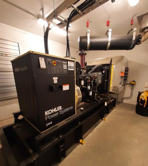
Measured Current Pulled by Pump Motor
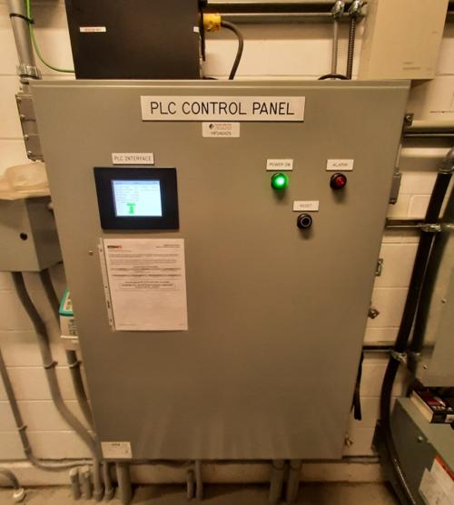
Proximity to Watercourses:
Description of Nearby Watercourse: Faulkner Creek
Flood of Record Elevation: Unknown
Flood Construction Level (FCL): Unknown
Lift Station Site Elevation: 450.4 m
Lift Station Flood Protection Measures: Unknown if lift station is above flood construction level.
Spill Protection Measures: Each pump provides adequate capacity for peak day
Data was taken from construction drawings as no record drawings were available. Actual conditions may differ.
1. Lift station located adjacent to Faulkner Creek, down a gravel access road from Horizon Drive. Lift station electrical and controls located in utility building.
2. Other lift stations contribute to this catchment. Failure of this lift station would impact a much larger area.
3. Isolation and check valves are located in wet well, confined space entry required to access/maintain.
4. Lift station has a standby generator, located in the utility building.
5. Lift station has flow meter, located in a manhole chamber. Confined space entry required to access/maintain.
6. Additional storage is provided by the old concrete wet well. Storage volume could not be determined as details for old wet well not provided.
7. No emergency storage as HWL alarm is above inlet pipe.
8. Operators noted site access is good.
9. Lift station is located approx. 12m from Faulkner Creek. Emergency discharge from Rose Valley dam flows into Faulkner Creek. Flood elevations are unknown, but City GIS shows the lift station and creek within 2m elevation difference.
1. Add valves to above ground valve chamber at next upgrade to eliminate confined space entry. Process mechanical equipment (pumps, piping, and valves) are 13 years old and expected to be in good condition, so an immediate upgrade not required.
2. Add flow meter to above ground valve chamber at next process mechanical upgrade to eliminate confined space entry.
3. Upgrade electrical and controls equipment in conjunction with process mechanical upgrade.
4. Complete testing of wet well at next upgrade to confirm condition (can be provided by Barski). Currently expected to be in good condition. If found in acceptable condition, wet well can remain.
5. Review additional safety considerations at time of replacement.
6. Civil piping can be maintained. Consider isolation of wet well inflows with knife gate valve in wet well or upstream of lift station.
7. Install bypass connection on forcemain for emergencies.
8. Review flood risk of lift station due to potential high flows from Faulkner Creek. Review emergency procedures for high creek levels and ensure there is a plan to prevent flooding of the lift station (i.e. sandbagging, tiger dam, etc.) if at risk.
Asset Type
(a) General Requirements
(b) Civil (Piping, Surface Works, Manhole)
(c) Structural (Building, Wet Well ³, Valve Chamber)
(d) Process Mechanical (Pumps, Process Piping, Valves, Odour Control)
(e) Building Mechanical (HVAC, Blower, Hoists, Plumbing, Emergency Eyewash & Shower) $100,000 (f) Electrical & Controls (Starts / VFDs / Service, Cables and Wiring, Controls, Instrumentation, Lighting, Standby Generator)
Notes:
1. Estimated costs are a preliminary Class D estimate in 2025 dollars.
2. Replacement value also includes replacement value of above stated recommendations, assuming those have been or will be implemented at the next lift station upgrade / replacement.
3. For purpose of estimating the lift station's full replacement value, the wet well is included in the replacement value, regardless if it will or will not be replaced at the next upgrade / replacement.
ATTRIBUTE
Note:
The condition assessment findings are based on background information, documentation, photos, and record drawings provided by the City, and discussions with City operators. No site visits were completed to physically assess the condition of the lift stations. As such, the quality of condition assessment findings is dependent on the quality of data provided to McElhanney, and may not fully represent site conditions.
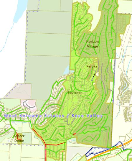
Record drawing not provided.
Pump performance curve not provided.
Year Installed: 2006
Municipal Address: 2325 Somerset Crt
Asset Number: LS#24
Catchment Area (ha): 2.6
IDENTIFICATION
Site Photo:
Service Population: 78 (current) 82 (20 Year Horizon Estimate)
Discharge Manhole: LV47
Last upgrade: Unknown
Other Info:
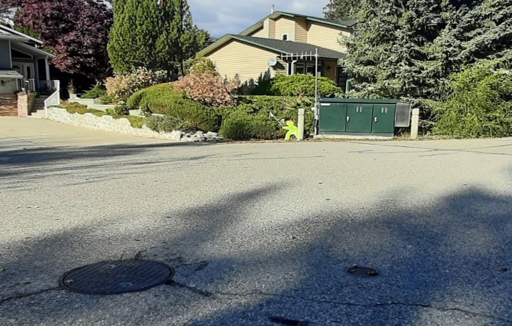
CONFIGURATION
General Configuration: Below ground wet well and valves with duplex submersible pumps
Wet Well Material: Concrete
Wet Well Diameter (m): 1.8
Wet Well Height (m): 5.02
Wet Well Condition: Good
Inlet Pipe Material PVC
Inlet Pipe Size (mm): 200
Components:
VFDs: No
Check Valve: Yes (50mm HDL Check Valve)
Isolation Valve: Yes (50mm Stainless Steel Ball Valve)
Access Hatches: Yes (MH Frame and Cover)
Emergency Response Items:
Standby Generator: No
Pump Bypass Connections: No
Portable Generator Connection: Yes (240V)
Emergency Suction: No Critical Spare Pump: Yes
Ladder: Yes (Rungs)
Platform: No
Odour Control: No
Ventilation: No
Wet Well Photo:Piping and Valving Photo:
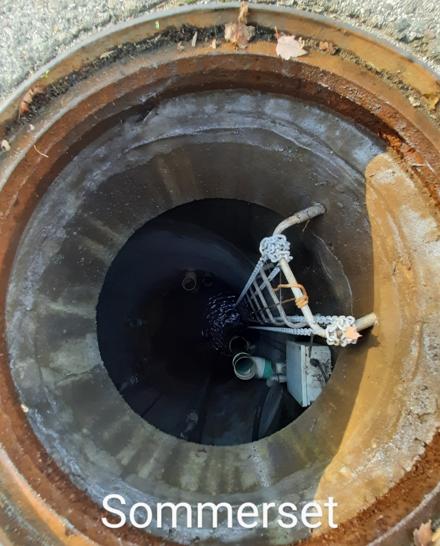
Pump #1Pump #2
Voltage: 230V230V Pump Discharge Size (mm): 50
Phase: 33 Header Material: Stainless Steel
Pump #2 nonoperational during site assessment
Power: 3 hp3 hp Header Size (mm): 75
Rotational Speed (rpm): 35203520
Make: FlygtFlygt
Model No.: MF3085MF3085
Impeller Number: 143143
Serial Number: 172-0650390172-0650391
Install Year: UnknownUnknown
Flow Rate (L/s): 2.6n/a Drawdown Test
Total Dynamic Head (m): 19n/a Design *Bylaw velocities: min. 1 m/s, max. 3.5m/s
Flow Records Information (2022-2024 Data)
Domestic Flow Rate (DFR) (L/cap/day): Undetermined
Pump Capacity (Max. Day Flow):
Average Day Flow (L/s): Undetermined
Maximum Day Flow (L/s) (Existing): 0.49 (Estimated from Modelling)
Maximum Day Flow (L/s) (20 Year): 0.53 (Estimated from Modelling)
Bylaw Flow Estimates
Average Dry Weather Flow - Current (L/s): 0.32 at 350 L/cap/day
Average Dry Weather Flow - Future (L/s): 0.33 at 350 L/cap/day
Pump Cycle Time - Current (2022-2024 Data) at Average Day Flow (min): Undetermined Starts per Hour (per Pump)*: Undetermined at Maximum Day Flow (min): 42.60 Starts per Hour (per Pump)*: 0.7
*Bylaw maximum pump starts - 4 times per hour per pump
Station Supply: 240V
STATION ELECTRICAL AND CONTROL
Instrumentation & Controls Phase: 1 PLC: Direct Logic 205 D2-09B-1
Transformer Size (kVA): Unknown Flow Meter: No Main Breaker (A): 50 Level Control: Yes UPS Power Capacity (VA): 1000
Generator
Model: n/a
Power Rating (kW): n/a
Fuel Source: n/a
Pressure Transmitter: No
Pressure Gauge: No
SCADA Integration: Yes
Alarms Functioning: Yes
Measured Current Pulled by Pump Motor
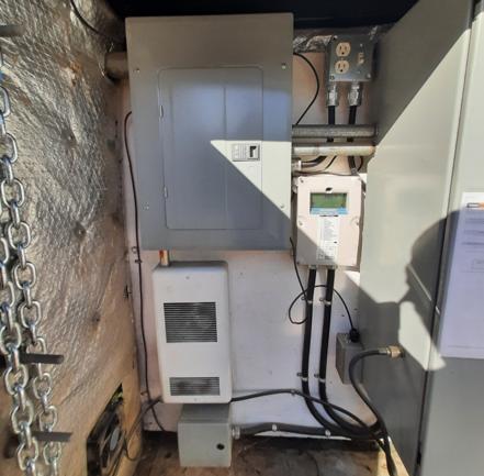
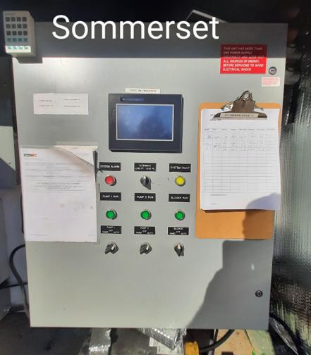
Proximity to Watercourses:
Description of Nearby Watercourse: None
Flood of Record Elevation: n/a
Flood Construction Level (FCL): n/a
Lift Station Site Elevation: 460.84
Lift Station Flood Protection Measures: n/a
Spill Protection Measures: Each pump provides adequate capacity for peak day
Lift station was assessed on October 15, 2025 as part of another project. Field observations noted here.
1. Lift station located in a concrete manhole in the middle of a cul-de-sac at the end of Somerset Court with good access.
2. Valves (ball and check) are located in concrete wet well. Confined space entry required to operate.
3. Lift station does not have a standby generator. Emergency storage is calculated to be 1,019L (approx. 32 minute) at maximum day flow. Inadequate for response during high traffice events, but acceptable during night.
4. Lift station aged (19 years old - 2006) with no major renewal. Generally in good condition.
5. Pump 2 was non-operational during site assessment. Operator noted that electrical team will replace.
6. Lift station does not have a flow meter. Pump drawdown test completed to determine pumping rate for operational pump.
7. Pump curve shows overall efficiency at approx. 19%, operating far right on the pump curve.
8. Lift station has no odour control. No odour issues noted.
9. Lift station has soft discharge tubes coming up to a header with cam lock, which Operators have noted they would like replaced.
10. Pumps have no guide rail system, so confined space entry is required to change out pumps. Due to the confined nature of this lift station, operators require entry on a swing chair, which is difficult.
11. Operators would like the manhole lid replaced with a double-winged road rated hatch to provide better access to the wet well.
1. Upgrade pumps with guide rail system and add double-winged road rated hatch with safety grates, so operators can complete maintenance and change out pumps without having to access the wet well with a swing chair. Addresses immediate confined space entry concerns.
2. Review pump selection at time of renewal to select a pump with improved efficiency.
3. Add valves to above ground valve chamber to eliminate confined space entry at next upgrade. Mechanical process equipment (pumps, piping, and valves) generally in good condition, so an immediate upgrade not requied.
4. Add flow meter to lift station with process mechanical upgrade. Flow meter to be located in above ground valve kiosk.
5. Upgrade electrical and controls equipment in conjunction with process mechanical upgrade. PLC may require an earlier upgrade as becoming outdated.
6. Review condition of existing concrete wet well at next upgrade. Currently in good condition. If significant deterioration in condition found at next upgrade, replace, or an FRP slip lining upgrade could be installed if feasible.
7. Review additional safety considerations at time of renewal.
8. Odour control may need to be added with above ground valve chamber upgrade. To be confirmed at renewal.
9. Install emergency suction line in wet well and bypass connection on forcemain for emergencies.
10. Civil piping can be maintained, but additional forcemain piping will be required once an above ground valve kiosk is added.
11. Consider isolation of wet well inflows with knife gate valve in wet well or upstream of lift station.
12. Review need for standby generator and add if needed.
13. Calibrate level control settings, so percentages are representative of wet well depth.
Asset Type
(a) General Requirements
(b) Civil (Piping, Surface Works, Manhole)
(c) Structural (Building, Wet Well³, Valve Chamber)
(d) Process Mechanical (Pumps, Process Piping, Valves, Odour Control)
(e) Building Mechanical (HVAC, Blower, Hoists, Plumbing, Emergency Eyewash & Shower) n/a (f) Electrical & Controls (Starts / VFDs / Service, Cables and Wiring, Controls, Instrumentation, Lighting)⁴
Notes:
1. Estimated costs are a preliminary Class D estimate in 2025 dollars.
2. Replacement value also includes replacement value of above stated recommendations, assuming those have been or will be implemented at the next lift station upgrade / replacement.
3. For purpose of estimating the lift station's full replacement value, the wet well is included in the replacement value, regardless if it will or will not be replaced at the next upgrade / replacement.
4. Standby generator not included in replacement cost.
Note:
The condition assessment findings are based on a field site assessment, background information, documentation, photos, and record drawings provided by the City, and discussions with City operators. The quality of condition assessment findings is dependent on the quality of data provided to McElhanney, and may not fully represent site conditions.
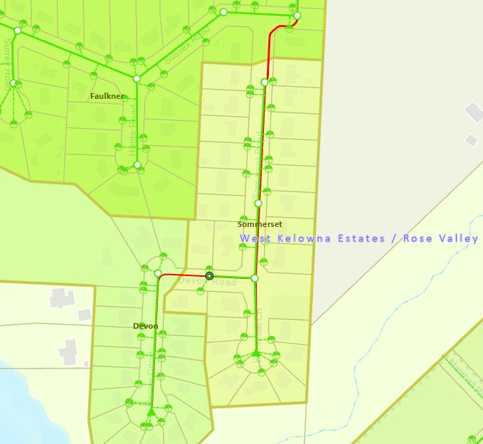
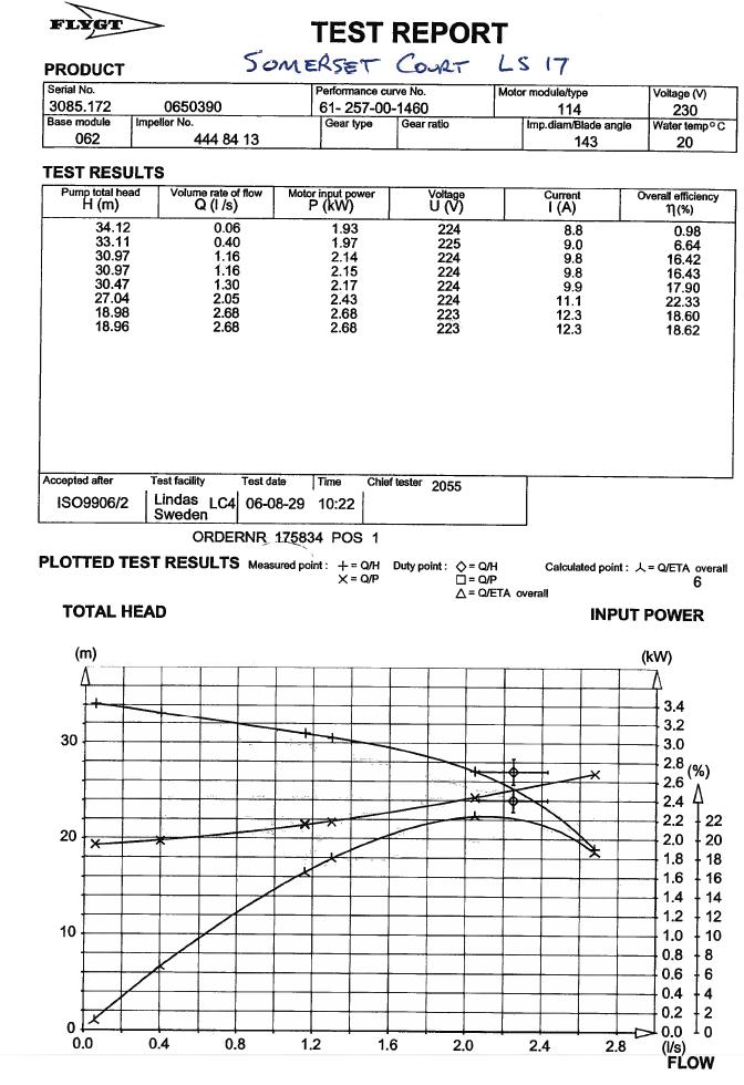
Year Installed: 2007
Municipal Address: 2329 Devon Crt
Asset Number: LS#25
Catchment Area (ha): 3.2
Site Photo:
Service Population: 54 (current) 59 (20 Year Horizon Estimate)
Discharge Manhole: LV47
Last upgrade: Unknown
Other Info:
Located in the cul-de-sac of Devon Court. Also known as Lakeview Phase 4. Catchment area has no contributing lift stations.
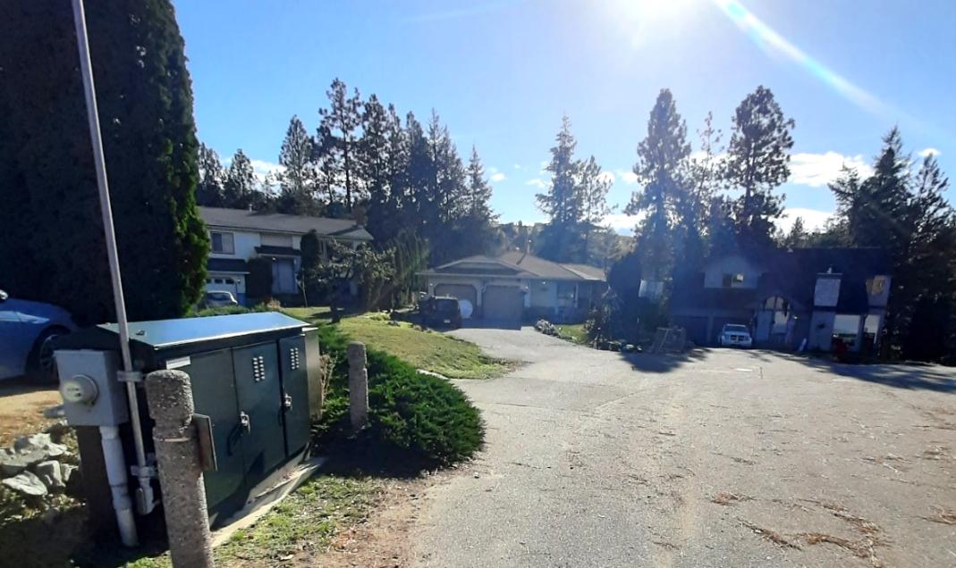
CONFIGURATION
General Configuration: Below ground wet well and valves with duplex submersible pumps
Wet Well Material: Concrete
Wet Well Diameter (m): 1.8
Wet Well Height (m): 4.25
Emergency Response Items:
Standby Generator: No
Wet Well Condition: Unknown Pump Bypass Connections: No
Inlet Pipe Material PVC
Inlet Pipe Size (mm): 200
Components:
VFDs: No
Check Valve: 50mm (Ball Valve)
Isolation Valve: Yes (50mm Stainless Steel Ball Valve)
Access Hatches: Yes (MH Frame and Cover)
Portable Generator Connection: Yes (240V)
Emergency Suction: No Critical Spare Pump: Yes
Ladder: Yes (Rungs)
Platform: No
Odour Control: No
Ventilation: Yes
Wet Well Photo:Piping and Valving Photo:
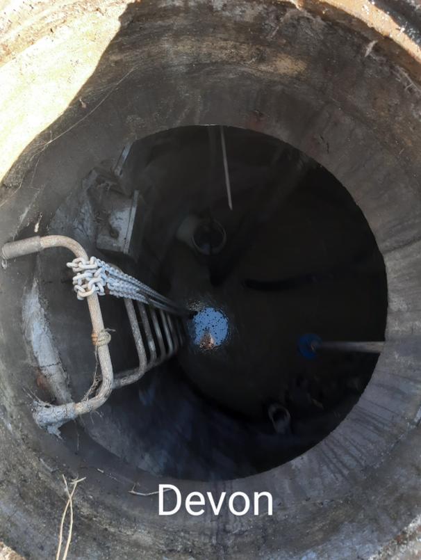
HYDRAULIC STORAGE CAPACITY
Actual Operating Storage (L): Undetermined
Emergency Storage Volume (L)*: Undetermined LeadLagPumps OffHWL AlarmLWL Alarm
Emergency Storage Time - Current (mins)**: Undetermined Setpoints (%) 5565357020
Emergency Storage Time - Future (mins)**: Undetermined Setpoint Depth (m) UndeterminedUndeterminedUndeterminedUndeterminedUndetermined
*High Water Alarm to sewer inlet pipe Volume (litres) UndeterminedUndetermined-Undetermined**at Maximum Day Flow
Pump #1Pump #2
230V230V
11
Power: 3 hp3 hp
Rotational Speed (rpm): 35203520
Make: FlygtFlygt
Model No.: MF3085MF3085
Impeller Number: 143143
Serial Number: 172-0650392172-0650393
Rate (L/s): 2.72.7
Total Dynamic Head (m): 19.319.3
Flow Records Information (2022-2024 Data) Pump Capacity (Max. Day Flow):
Domestic Flow Rate (DFR) (L/cap/day): Undetermined
Average Day Flow (L/s): Undetermined
Maximum Day Flow (L/s) (Existing): 0.44 (Estimated from Modelling)
Maximum Day Flow (L/s) (20 Year): 0.47 (Estimated from Modelling)
Bylaw Flow Estimates
Average Dry Weather Flow - Current (L/s): 0.22 at 350 L/cap/day
Average Dry Weather Flow - Future (L/s): 0.24 at 350 L/cap/day
Pump Cycle Time - Current (2022-2024 Data) at Average Day Flow (min): Undetermined
Starts per Hour (per Pump)*: Undetermined at Maximum Day Flow (min): Undetermined Starts per Hour (per Pump)*: Undetermined
*Bylaw maximum pump starts - 4 times per hour per pump
Station Supply: 230V
STATION ELECTRICAL AND CONTROL
Instrumentation & Controls
Phase: 1 PLC: Direct Logic 205 D2-09B-1
Transformer Size (kVA): Unknown
Main Breaker (A): Unknown
Flow Meter: No
Level Control: Yes UPS Power Capacity (VA): 1000
Generator
Model: n/a
Power Rating (kW): n/a
Fuel Source: n/a
Pressure Transmitter: No
Pressure Gauge: No
SCADA Integration: Yes
Alarms Functioning: Yes
Measured Current Pulled by Pump Motor FLOW RECORD INFORMATION
Kiosk - Electrical & Controls
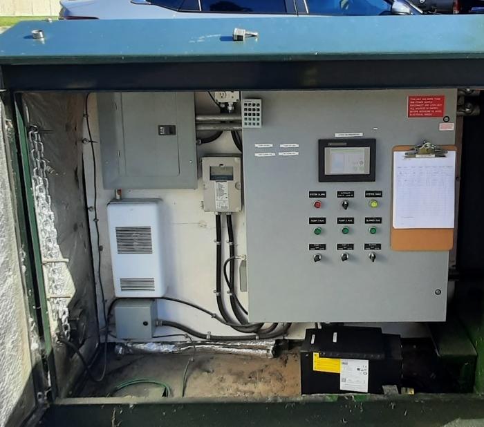
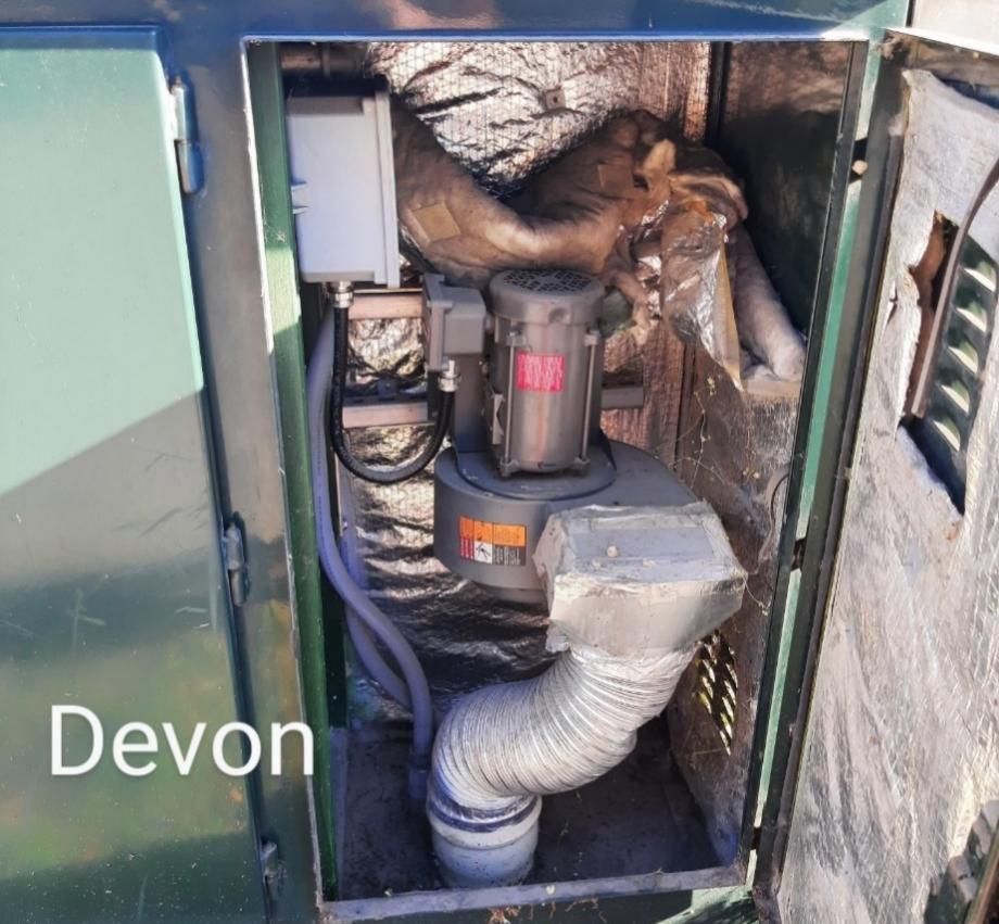
Proximity to Watercourses:
Description of Nearby Watercourse: None
Flood of Record Elevation: n/a
Flood Construction Level (FCL): n/a
Lift Station Site Elevation: 460.42
Lift Station Flood Protection Measures: n/a
Spill Protection Measures: Each pump provides adequate capacity for peak day
1. Recent flow data and setpoints were not provided. Assessment of items such as emergency storage volumes, domestic flow rates, and pump capacities could not be determined.
2. Lift station located in a concrete manhole in the middle of a cul-de-sac at the end of Devon Court with good access.
3. Valves (ball and check) are located in concrete wet well. Confined space entry required to operate.
4. Lift station does not have a standby generator or flow meter.
5. Lift station aged (18 years old - 2007) with no major renewal.
6. Pump test results shows overall efficiency is calculated to be approx. 15% at design flow.
7. Lift station has no odour control.
8. Operator noted the lift station has soft discharge tubes coming up to a header with cam lock that they would like replaced.
9. Operator also noted that it's almost impossible to pull pumps out and operators require entry on a swing chair.
10. Operators would like to see an upgrade to the pumps, piping and rail system as well as replacing the manhole lid with a double-winged road rated hatch.
1. A more thorough lift station assessment is recommended as records, flow data and setpoints are incomplete.
2. Assess condition of mechanical process equipment (pumps, piping, and valves), as they are nearing their end of life, and determine remaining life expectancy. If replacement is required, valves to be in above ground valve kiosk and add pump guide rails and stainless steel header.
3. Review pump selection at time of renewal to select a pump that is better suited for the system and operates near its BEP to increase pump efficiency.
4. Add flow meter to lift station with process mechanical upgrade. Flow meter to be located in above ground valve kiosk.
5. Upgrade aged electrical and controls equipment in conjunction with process mechanical upgrade. Include SCADA alarms.
6. Review condition of existing concrete wet well to confirm condition. If found in unacceptable condition, replace, or an FRP slip lining upgrade could be installed if feasible.
7. Review additional safety considerations at time of renewal, such as manhole lid replacement with a double-winged road rated hatch.
8. Review odour control at the time of above ground valve kiosk upgrade.
9. Install emergency suction line in wet well and bypass connection on forcemain for emergencies.
10. Civil piping can be maintained. Consider isolation of wet well inflows with knife gate valve in wet well or upstream of lift station.
11. Review need for standby generator and add if needed.
Asset Type
(a) General Requirements
(b) Civil (Piping, Surface Works, Manhole)
(c) Structural (Building, Wet Well³, Valve Chamber)
(d) Process Mechanical (Pumps, Process Piping, Valves, Odour Control)
(e) Building Mechanical (HVAC, Blower, Hoists, Plumbing, Emergency Eyewash & Shower) n/a (f) Electrical & Controls (Starts / VFDs / Service, Cables and Wiring, Controls, Instrumentation, Lighting)⁴
Notes:
1. Estimated costs are a preliminary Class D estimate in 2025 dollars.
2. Replacement value also includes replacement value of above stated recommendations, assuming those have been or will be implemented at the next lift station upgrade / replacement.
3. For purpose of estimating the lift station's full replacement value, the wet well is included in the replacement value, regardless if it will or will not be replaced at the next upgrade / replacement.
4. Standby generator not included in replacement cost.
Consequence of Failure
Note: The condition assessment findings are based on background information, documentation, photos, and record drawings provided by the City, and discussions with City operators. No site visits were completed to physically assess the condition of the lift stations. As such, the quality of condition assessment findings is dependent on the quality of data provided to McElhanney, and may not fully represent site conditions.
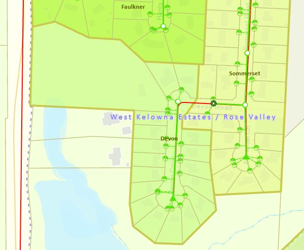
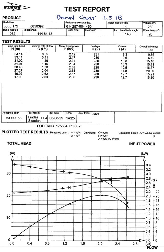
IDENTIFICATION
Year Installed: 2018 (assumed) Site Photo:
Municipal Address: 3001 Riesling Place
Asset Number: LS#26
Catchment Area (ha): 1.4
Service Population: 92 (current) 100 (20 Year Horizon Estimate)
Discharge Manhole: EB1-8
Last upgrade: Unknown
Other Info:
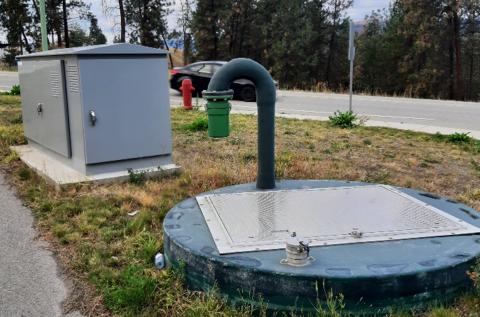
CONFIGURATION
General Configuration: Below ground wet well and valves with duplex submersible pumps
Wet Well Material: FRP
Wet Well Diameter (m): 2.44
Emergency Response Items:
Wet Well Height (m): 6.1 Standby Generator: No
Wet Well Condition: Unknown
Inlet Pipe Material PVC
Inlet Pipe Size (mm): 200
Components:
VFDs: Penair Myers 4VX50M423
Check Valve: Yes
Isolation Valve: Yes
Access Hatches: Yes (Aluminum)
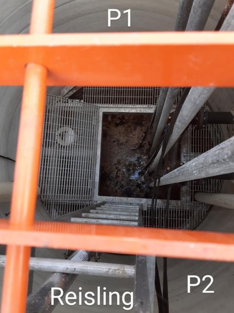
Pump Bypass Connections: No
Portable Generator Connection: Yes
Emergency Suction: Yes Critical Spare Pump: No
Ladder: Yes
Platform: Yes
Odour Control: Yes (Odour Control Valve)
Ventilation: Yes (Gooseneck)
Wet Well Photo:Piping and Valving Photo:
Located at the corner of Riesling Place and East Boundary Road. Catchment area has no contributing lift stations. No photo available
Actual Operating Storage (L): Undetermined
Emergency Storage Volume (L)*: Undetermined LeadLagPumps OffHWL AlarmLWL Alarm
Emergency Storage Time - Current (mins)**: Undetermined Setpoints (%) 7075508045
Emergency Storage Time - Future (mins)**: Undetermined Setpoint Depth (m) UndeterminedUndeterminedUndeterminedUndeterminedUndetermined *High Water Alarm to sewer inlet pipe Volume (litres) UndeterminedUndetermined-Undetermined**at Maximum Day Flow
Header Pump #1Pump #2 Pump
Power: 5 hp5 hp
Rotational Speed (rpm): 17501750
Make: MyersMyers
Model No.: 4VX4VX
Impeller Number: UnknownUnknown
Serial Number: 4VX50M4-23 (15-2661) 4VX50M4-23 (15266-2)
Install Year: UnknownUnknown
Flow Records Information (2022-2024 Data)
Domestic Flow Rate (DFR) (L/cap/day): Undetermined
Average Day Flow (L/s): Undetermined
Maximum Day Flow (L/s) (Existing): 0.48 (Estimated from Modelling)
Maximum Day Flow (L/s) (20 Year): 0.53 (Estimated from Modelling)
Bylaw Flow Estimates
Average Dry Weather Flow - Current (L/s): 0.37 at 350 L/cap/day
Average Dry Weather Flow - Future (L/s): 0.41 at 350 L/cap/day
Pump Cycle Time - Current (2022-2024 Data)
at Average Day Flow (min): Undetermined Starts per Hour (per Pump)*: Undetermined at Maximum Day Flow (min): Undetermined Starts per Hour (per Pump)*: Undetermined *Bylaw maximum pump starts - 4 times per hour per pump
Station Supply: 600V
Pump Capacity (Max. Day Flow):
Instrumentation & Controls
Phase: 3 PLC: Direct Logic 06 D0-06DR
Transformer Size (kVA): Unknown
Main Breaker (A): 100
UPS Power Capacity (VA): 1000
Generator
Model: n/a
Power Rating (kW): n/a
Fuel Source: n/a
Flow Meter: Yes
Level Control: Unknown
Pressure Transmitter: No
Pressure Gauge: No
SCADA Integration: Yes
Alarms Functioning: Yes
STATION ELECTRICAL AND CONTROL Measured Current Pulled by Pump Motor
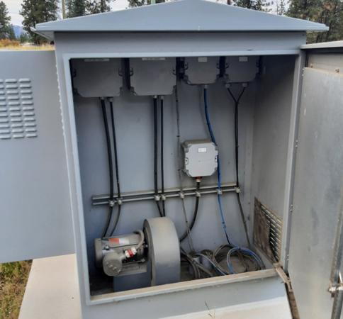
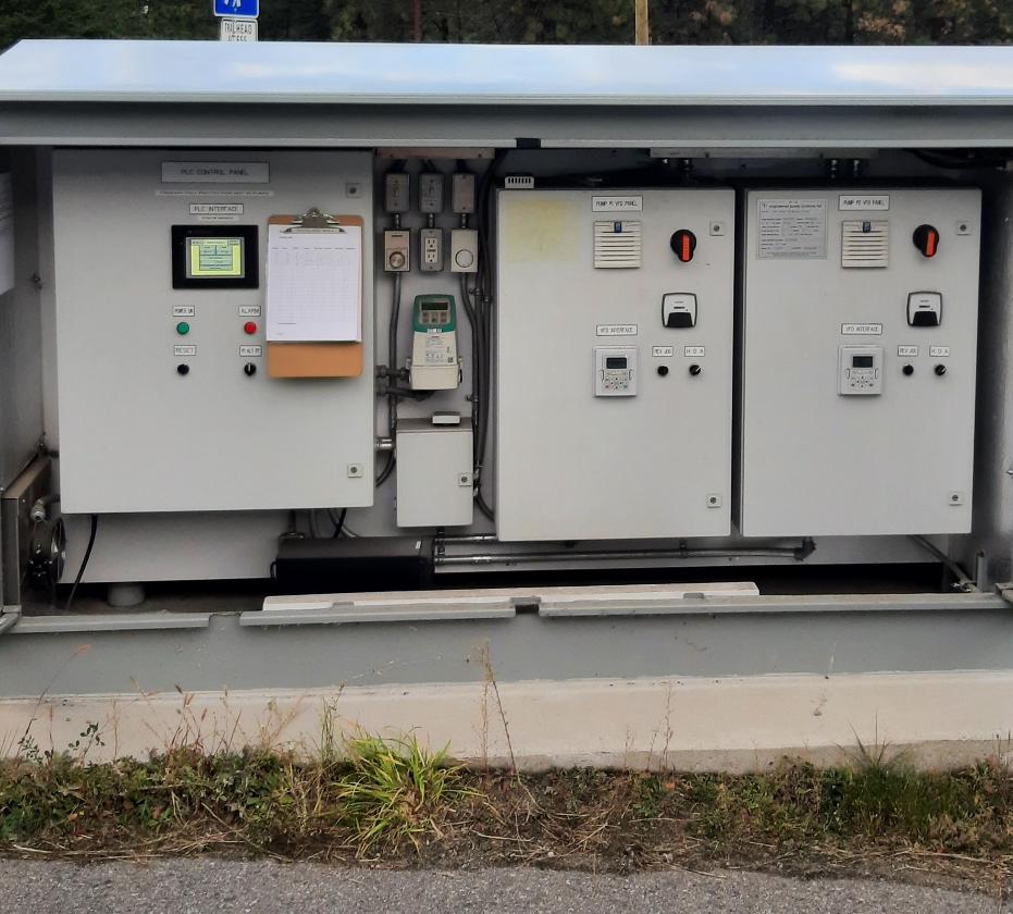
Proximity to Watercourses:
Description of Nearby Watercourse: None
Flood of Record Elevation: n/a
Flood Construction Level (FCL): n/a
Lift Station Site Elevation: 463.0 m
Lift Station Flood Protection Measures: n/a
Spill Protection Measures: Each pump provides adequate capacity for peak day
1. Record drawings, pump curves flow data and setpoints were not provided for this lift station and as such, assessment of items such as emergency storage volumes and domestic flow rates could not be determined.
2. Lift station located on City right-of-way at the corner of Riesling Place and East Boundary Road. Site is not fenced.
3. Forcemain velocity is only 0.9 m/s and does not meet the City bylaw minimum (1.0 m/s)
4. Lift station does not have a standby generator, but has a transfer switch.
5. Lift station does have a flow meter.
6. Lift station is approximately 7 years old according to operators, assumed to be installed in 2018. Was intended to be owned by a private strata; however, ownership was transferred to the City.
7. Operators noted it is an okay station. Electrician is upgrading/adding receptable for future generator. Also noted it is not a priority station for upgrades.
8. Site access is good with parking off of Riesling Way.
9. Lift station has no critical spare pump.
1. A more thorough lift station assessment is recommended as records and data are incomplete.
2. Assess condition of mechanical process equipment (pumps and piping) around 15-20 years from installation and determine remaining life expectancy. When replacement is required, move valves to an above ground valve chamber (Barski). An earlier upgrade could be explored to eliminate the confined space entry requirements.
3. Upgrade electrical and controls equipment in conjunction with process mechanical upgrade.
4. Complete testing of existing wet well at time of mechanical process equipment assessment to confirm condition (can be provided by Barski). If found in acceptable condition, wet well can remain.
5. Review additional safety considerations at time of replacement.
6. Review odour control at the time of above ground valve kiosk upgrade.
7. Install bypass connection on forcemain for emergencies.
8. Civil piping can be maintained. Consider isolation of wet well inflows with knife gate valve in wet well or upstream of lift station.
9. Review need for standby generator and add if needed. Procure critical spare pump.
10. Consider increasing pump flow rate on next upgrade to increase forcemain velocities, so that minimum scouring velocity is met.
Asset Type
(a) General Requirements
(b) Civil (Piping, Surface Works, Manhole)
(c) Structural (Building, Wet Well³, Valve Chamber)
(d) Process Mechanical (Pumps, Process Piping, Valves, Odour Control)
(e) Building Mechanical (HVAC, Blower, Hoists, Plumbing, Emergency Eyewash & Shower) n/a (f) Electrical & Controls (Starts / VFDs / Service, Cables and Wiring, Controls, Instrumentation, Lighting)⁴
Notes:
1. Estimated costs are a preliminary Class D estimate in 2025 dollars.
2. Replacement value also includes replacement value of above stated recommendations, assuming those have been or will be implemented at the next lift station upgrade / replacement.
3. For purpose of estimating the lift station's full replacement value, the wet well is included in the replacement value, regardless if it will or will not be replaced at the next upgrade / replacement.
4. Standby generator not included in replacement cost.
Note:
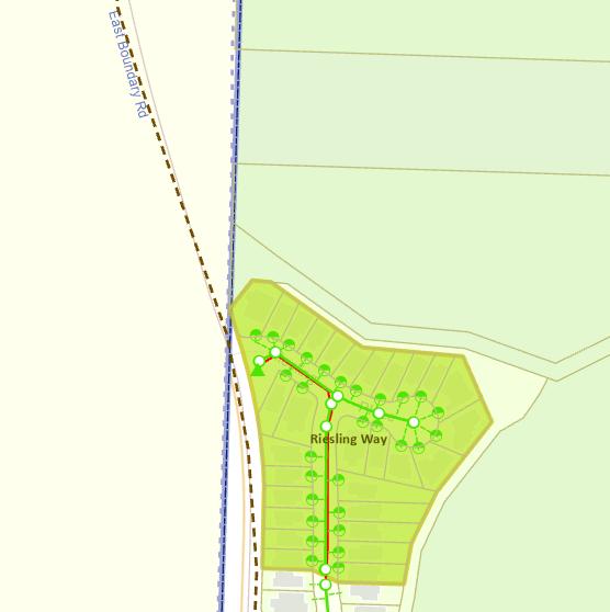
Record drawing not provided.
Pump performance curve not provided.
Year Installed: 1991
Municipal Address: 481 Casa Rio Drive
Asset Number: LS#27
Catchment Area (ha): 1.6
Site Photo:
Service Population: 47 (current) 61 (20 Year Horizon Estimate)
Discharge Manhole: CL14
Last upgrade: 2018
Other Info:
Located within Casa Rio Park near Okanagan Lake. Catchment area has no contributing lift stations.
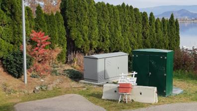
CONFIGURATION
General Configuration: Wet well with above ground valves and duplex submersible pumps
Wet Well Material: FRP
Wet Well Diameter (m): 2.44
Emergency Response Items:
Wet Well Height (m): 7.22 Standby Generator: No
Wet Well Condition: Unknown
Pump Bypass Connections: No
Inlet Pipe Material PVC Portable Generator Connection: Yes
Inlet Pipe Size (mm): 200 Emergency Suction: Yes Critical Spare Pump: Yes
Components:
VFDs: No
Check Valve: Yes (75mm HDL Ball Check Valve)
Isolation Valve: Yes (75mm Val-matic Plug Valve)
Access Hatches: Yes
Ladder: Yes (Aluminum)
Platform: Yes (FRP)
Odour Control: Yes (Injections)
Ventilation: Yes (Gooseneck)
Wet Well Photo:Piping and Valving Photo:
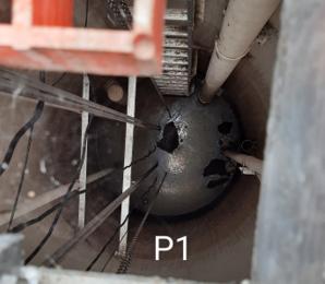
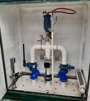
Pump #1Pump #2
220V220V
11
3 hp3 hp
Rotational Speed (rpm): 35103510
Make: FlygtFlygt
Model No.: MP3085HTMP3085HT
Impeller Number: 258258
Serial Number: 3085.172-17401493085.172-170150
Install Year: 20182018
Flow Rate (L/s): 3.73.7
Total Dynamic Head (m): 13.713.7 Design *Small portion of forcemain is 75mm PVC **Bylaw velocities: min. 1 m/s, max. 3.5m/s
Flow Records Information (2022-2024 Data)
Domestic Flow Rate (DFR) (L/cap/day): Undetermined
FLOW RECORD INFORMATION
Pump Capacity (Max. Day Flow):
Average Day Flow (L/s): Undetermined
Maximum Day Flow (L/s) (Existing): 0.32 (Estimated from Modelling)
Maximum Day Flow (L/s) (20 Year): 0.36 (Estimated from Modelling)
Bylaw Flow Estimates
Average Dry Weather Flow - Current (L/s): 0.19 at 350 L/cap/day
Average Dry Weather Flow - Future (L/s): 0.25 at 350 L/cap/day
Pump Cycle Time - Current (2022-2024 Data) at Average Day Flow (min): Undetermined Starts per Hour (per Pump)*: Undetermined at Maximum Day Flow (min): Undetermined Starts per Hour (per Pump)*: Undetermined *Bylaw maximum pump starts - 4 times per hour per pump
STATION ELECTRICAL AND CONTROL
Station Supply: 600V
Instrumentation & Controls Phase: 3
Transformer Size (kVA): Unknown
Main Breaker (A): 100 Level Control: Yes
UPS Power Capacity (VA): 1000
Generator
Model: n/a
Power Rating (kW): n/a
Fuel Source: n/a
Pressure Transmitter: Yes (Ultrasonic)
Pressure Gauge: Yes
SCADA Integration: Yes
Alarms Functioning: Yes
Measured Current Pulled by Pump Motor
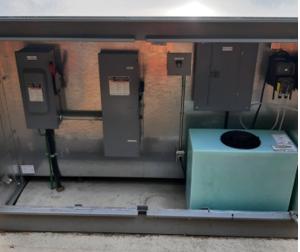
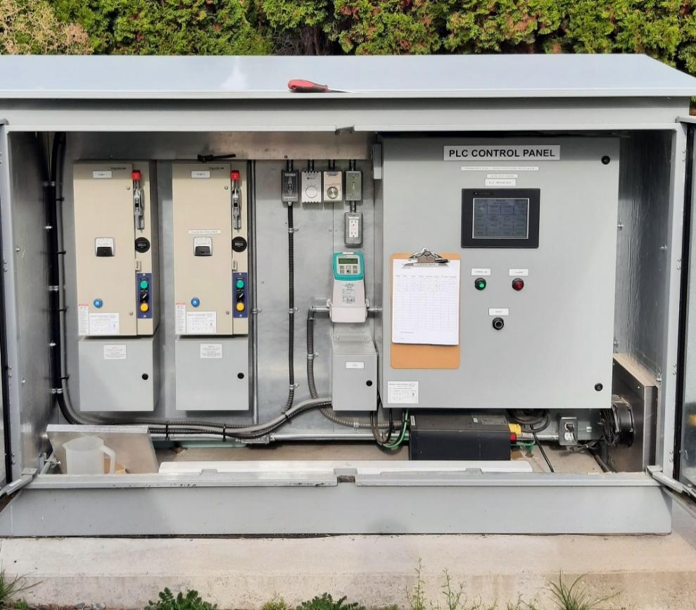
Proximity to Watercourses:
Description of Nearby Watercourse: Okanagan Lake
(Okanagan Basin Water Board)
(CoWK Bylaw No. 265)
Lift Station Flood Protection Measures: Above Flood Construction Level
Spill Protection Measures: Each pump provides adequate capacity for peak day
1. Pump curves, flow data and setpoints were not provided for this lift station and as such, assessment of items such as domestic flow rates, and pump capacities could not be determined.
2. Valves (plug and check) are located in above ground kiosk.
3. Lift station does not have a standby generator or transfer switch. No emergency storage as HWL alarm is above inlet pipe.
4. Lift station has a flow meter.
5. Lift station underwent a major upgrade in 2018 with new wet well, process mechnical, civil works, and electrical and controls.
6. Site is accessed via an asphalt driveway downslope into the Casa Rio Waterfront Park.
7. Lift station receives calcium nitrate injections (BioMaxx) for odour control.
8. Operators noted this is a "beautiful" station. There are no deficiencies noted by the City.
1. A more thorough lift station flow assessment is recommended as records and data are incomplete.
2. Review need for standby generator and add if needed. Consider installing a transfer switch.
Civil (Piping, Surface Works, Manhole)
(c) Structural (Building, Wet Well³, Valve Chamber)
(d) Process Mechanical (Pumps, Process Piping, Valves, Odour Control)
(e) Building Mechanical (HVAC, Blower, Hoists, Plumbing, Emergency Eyewash & Shower)
(f) Electrical & Controls (Starts / VFDs / Service, Cables and Wiring, Controls, Instrumentation,
Notes:
1. Estimated costs are a preliminary Class D estimate in 2025 dollars.
2. Replacement value also includes replacement value of above stated recommendations, assuming those have been or will be implemented at the next lift station upgrade / replacement.
3. For purpose of estimating the lift station's full replacement value, the wet well is included in the replacement value, regardless if it will or will not be replaced at the next upgrade / replacement.
4. Standby generator not included in replacement cost.
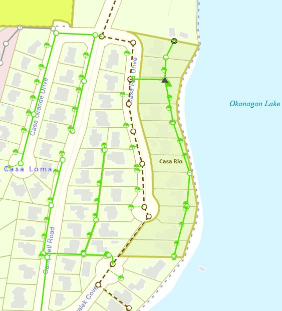
Pump performance curve not provided.
Year Installed: 1993
IDENTIFICATION
Site Photo:
Municipal Address: 2821 East Boundary Road
Asset Number: LS#28
Catchment Area (ha): 234.7
Service Population: 4,276 (current) 11,191 (20 Year Horizon Estimate)
Discharge Manhole: 2EBT6
Last upgrade: 2018
Other Info:
Located in the parking lot for the Mount Boucherie Sports Fields on East Boundary Road. Contributing lift stations include Ross, Brentwood, Stevens, Faulkner Creek, Horizon Village, Hayman, Bridgeview, Somerset, Devon Court, and Keloka Lift Stations. Total catchment area with contributing catchments = 679.6 ha.
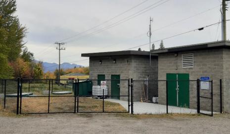
CONFIGURATION
General Configuration: Below ground wet well with duplex submersible pumps (plus space for future third pump). Controls and valves located inside building.
Wet Well Material: FRP
Wet Well Diameter (m): 3.65
Wet Well Height (m): 7.4
Emergency Response Items:
Standby Generator: Yes
Wet Well Condition: Unknown Pump Bypass Connections: No
Inlet Pipe Material PVC
Inlet Pipe Size (mm): 450
Components:
VFDs: Yes
Check Valve: Yes (250mm HDL Ball Check Valve)
Isolation Valve: Yes (250mm Val-Matic Plug Valve)
Access Hatches: Yes (Aluminum)
Portable Generator Connection: No
Emergency Suction: Yes Critical Spare Pump: Yes
Ladder: Yes
Platform: No
Odour Control: Yes (Carbon Filter and Injections)
Ventilation: Yes (Gooseneck)
Wet Well Photo:Piping and Valving Photo:
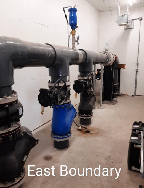
575 V575 V
33
Rotational Speed (rpm): 11851185
Make: FlygtFlygt
Model No.: NP3301.185MTNP3301.185MT
Impeller Number: 638638
FLOW RECORD INFORMATION
Maximum Day Flow (L/s) (20 Year):
Bylaw Flow Estimates
Average Dry Weather Flow - Current (L/s): 17.32 at 350 L/cap/day Average Dry Weather Flow - Future (L/s):
Pump Cycle Time - Current (2022-2024 Data)
Station Supply: 575V
(kVA): 30
(A): 400
& Controls
Control: Yes UPS Power Capacity (VA): 1000 Pressure Transmitter: Yes Pressure Gauge: Yes Generator SCADA Integration: Yes
Model: Kohler 200RE0ZJF Alarms Functioning: Yes Power Rating (kW): 200 Fuel Source: Diesel
STATION ELECTRICAL AND CONTROL Measured Current Pulled by Pump Motor
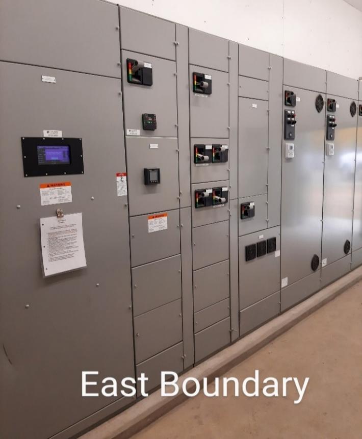
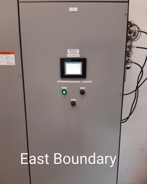
Proximity to Watercourses:
Description of Nearby Watercourse: None Flood of Record Elevation: n/a Flood Construction Level (FCL): n/a
Lift Station Site Elevation: 459.25
Lift Station Flood Protection Measures: n/a
Spill Protection Measures: Each pump provides adequate capacity for peak day
1. The design flow from the record drawing (198.5 L/s) does not match the provided HMI image flows (83 L/s).
2. Lift station located in the parking lot of the Mount Boucherie Sports Fields on East Boundary Road, and is fenced. Valves and electrical and controls are located inside a utility building. Lift station pumps into RDCO East Trunk forcemain.
3. Lift station is 32 years old (1993) with a major upgrade in 2018 (see record drawings). The upgrade included a new wet well, two new submersible pumps with space for a future third pump, a new utility building with a new mechanical and electrical room, and a standby generator. Old utility building converted to storage.
4.The standby generator is located outside the utility building within the fenced site.
5. No emergency storage within the new wet well as HWL alarm is above the inlet pipe. The 2018 upgrade included reconfiguring the piping and installing a bypass around the original 1993 wet well, which could potentially is being or could be used as emergency storage.
6. The calculated domestic flow rate of 1,282 L/cap/day is significant (four times the bylaw value of 350 L/cap/day).
7. Other lift stations contribute to this catchment. Failure of this lift station would impact a much larger area.
8. Lift station has functioning flow meter.
9. Operators note that East Boundary is the City's busiest lift station.
10. Site access is good with vehicle access and parking adjacent to the fenced site.
11. Lift station receives calcium nitrate injections (BioMaxx) for odour control.
12. There are no deficiencies noted by the City.
1. A more thorough review of lift station flows is recommended to investigate the discrepancy between the design flow and actual HMI flow.
2. Operators requested an assessment to determine if additional storage is necessary.
3. Investigate high domestic flow rate. Review data to eliminate potential errors or instrumentation in need of calibration. Complete wet well drawing test to confirm pump flow rate. Also look into potential infiltration from high ground water.
Asset Type
(a) General Requirements
(b) Civil (Piping, Surface Works, Manhole)
(c) Structural (Building, Wet Well³, Valve Chamber)
(d) Process Mechanical (Pumps, Process Piping, Valves, Odour Control)
(e) Building Mechanical (HVAC, Blower, Hoists, Plumbing, Emergency Eyewash & Shower)
(f) Electrical & Controls (Starts / VFDs / Service, Cables and Wiring, Controls, Instrumentation, Lighting, Standby Generator)
Notes:
1. Estimated costs are a preliminary Class D estimate in 2025 dollars.
2. Replacement value also includes replacement value of above stated recommendations, assuming those have been or will be implemented at the next lift station upgrade / replacement.
3. For purpose of estimating the lift station's full replacement value, the wet well is included in the replacement value, regardless if it will or will not be replaced at the next upgrade / replacement.
Consequence of Failure
Catchment area map not available.
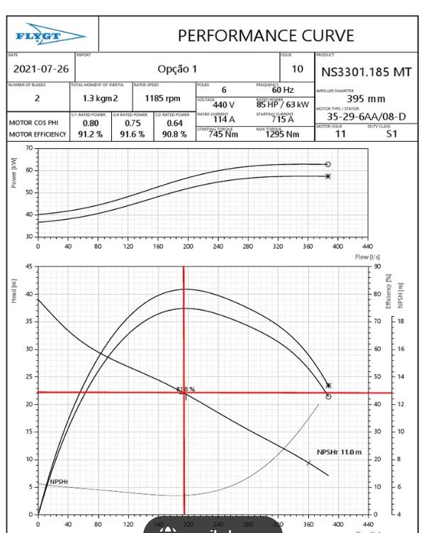
Year Installed: 2024
Municipal Address: 3731 Old Okanagan Highway
Asset Number: LS#29
Catchment Area (ha): Unknown
IDENTIFICATION
Site Photo:
Service Population: 0 (current) 0 (20 Year Horizon Estimate)
Discharge Manhole: Unknown
Last upgrade: N/A
Other Info:
Located adjacent to the new City Hall. Catchment area has no contributing lift stations.
CONFIGURATION
General Configuration: Wet well with above ground valves with duplex submersible pumps
Wet Well Material: Unknown
Wet Well Diameter (m): 1.52
Wet Well Height (m): 4.4
Emergency Response Items:
Standby Generator: No
Wet Well Condition: Unknown Pump Bypass Connections: No
Inlet Pipe Material PVC
Inlet Pipe Size (mm): 150
Components:
VFDs: No
Check Valve: Yes (75mm M.A. Stewart Swing Check Valve)
Isolation Valve: Yes (75mm Homestead Plug Valve)
Access Hatches: Yes (Aluminum)
Portable Generator Connection: No
Emergency Suction: No Critical Spare Pump: No
Ladder: No
Platform: No
Odour Control: Yes (Wagner Sewer Valve)
Ventilation: Yes
Wet Well Photo:Piping and Valving Photo:
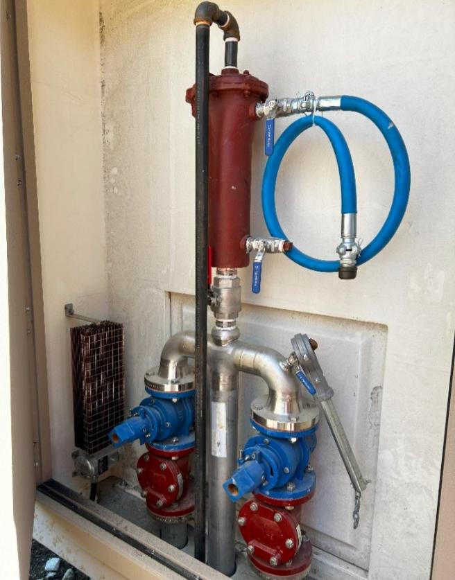
Actual Operating Storage (L): Undetermined
Emergency Storage Volume (L)*: Undetermined LeadLagPumps OffHWL AlarmLWL Alarm
Emergency Storage Time - Current (mins)**: Undetermined Setpoints (%) UnknownUnknownUnknownUnknownUnknown
Emergency Storage Time - Future (mins)**: Undetermined Setpoint Depth (m) UndeterminedUndeterminedUndeterminedUndeterminedUndetermined
*High Water Alarm to sewer inlet pipe Volume (litres) UndeterminedUndetermined-Undetermined**at Maximum Day Flow
Pump #1Pump #2
Voltage: 230V230V
Phase: 33
Power: 5 hp5 hp
Rotational Speed (rpm): 17501750
Make: ZoellerZoeller
Model No.: EX 6124EX 6124
Impeller Number: UnknownUnknown
Serial Number: UnknownUnknown
Flow Rate (L/s): 55
Total Dynamic Head (m): 7.37.3
Flow Records Information (2022-2024 Data)
Domestic Flow Rate (DFR) (L/cap/day): Undetermined
Average Day Flow (L/s): Undetermined
Pump Capacity (Max. Day Flow):
Maximum Day Flow (L/s) (Existing): 0.26 (Estimated from Modelling)
Maximum Day Flow (L/s) (20 Year): 0.26 (Estimated from Modelling)
Bylaw Flow Estimates
Average Dry Weather Flow - Current (L/s): 0.00 at 350 L/cap/day
Average Dry Weather Flow - Future (L/s): 0.00 at 350 L/cap/day
Pump Cycle Time - Current (2022-2024 Data) at Average Day Flow (min): Undetermined Starts per Hour (per Pump)*: Undetermined at Maximum Day Flow (min): Undetermined Starts per Hour (per Pump)*: Undetermined *Bylaw maximum pump starts - 4 times per hour per pump
Station Supply: 600V
STATION ELECTRICAL AND CONTROL
Instrumentation & Controls
Phase: 3 PLC: Schneider Zelio SR3 B101FU
Transformer Size (kVA): Unknown
Main Breaker (A): 25.3
UPS Power Capacity (VA): Unknown
Generator
Model: n/a
Power Rating (kW): n/a
Fuel Source: n/a
Flow Meter: Unknown
Level Control: Yes (Siemens)
Pressure Transmitter: No
Pressure Gauge: No
SCADA Integration: No
Alarms Functioning: Yes
Measured Current Pulled by Pump Motor
Kiosk - Electrical Side
Proximity to Watercourses:
Description of Nearby Watercourse: Unknown
Flood of Record Elevation: Unknown
Flood Construction Level (FCL): Unknown
Lift Station Site Elevation: 398.7m
Lift Station Flood Protection Measures: Unknown
1. Record drawings, pump curves, photos, setpoints and flow data were not provided for this lift station. Assessment of items such as emergency storage volumes, domestic flow rates, and pump capacities could not be determined.
2. Lift station located beside the new West Kelowna City Hall.
3. Valves (plug and check) are located in above ground kiosk.
4. Lift station does not have a standby generator or transfer switch.
5. Operators noted flow meter (if it exists) does not communicate. No SCADA alarms.
6. Lift station is newly constructed in 2024. Operators noted there has been no formal commissioning.
7. Operators noted site access is terrible. No photos showing site were provided.
8. Lift station has no critical spare pump.
1. A more thorough lift station assessment is recommended as records and data are incomplete.
2. Procure critical spare pump.
3. Determine if flow meter exists. Set up with SCADA communications.
4. Review need for standby generator and add if needed. Consider adding a transfer switch.
Spill Protection Measures: Each pump provides adequate capacity for peak day Asset Type
(a) General Requirements
(b) Civil (Piping, Surface Works, Manhole)
(c) Structural (Building, Wet Well³, Valve Chamber)
(d) Process Mechanical (Pumps, Process Piping, Valves, Odour Control)
(e) Building Mechanical (HVAC, Blower, Hoists, Plumbing, Emergency Eyewash & Shower) n/a (f) Electrical & Controls (Starts / VFDs / Service, Cables and Wiring, Controls, Instrumentation, Lighting)⁴
Notes:
1. Estimated costs are a preliminary Class D estimate in 2025 dollars.
2. Replacement value also includes replacement value of above stated recommendations, assuming those have been or will be implemented at the next lift station upgrade / replacement.
3. For purpose of estimating the lift station's full replacement value, the wet well is included in the replacement value, regardless if it will or will not be replaced at the next upgrade / replacement.
Note:
Catchment area map not available (City Hall lift station not yet in City GIS).
Note: Record drawing not provided. Issued for Construction drawing shown below (may not match with installed).
Pump performance curve not provided.