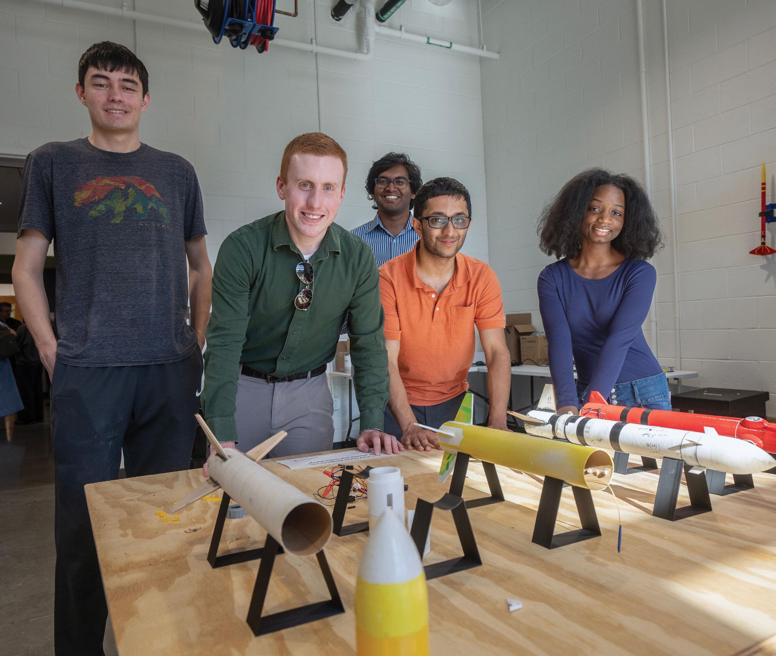
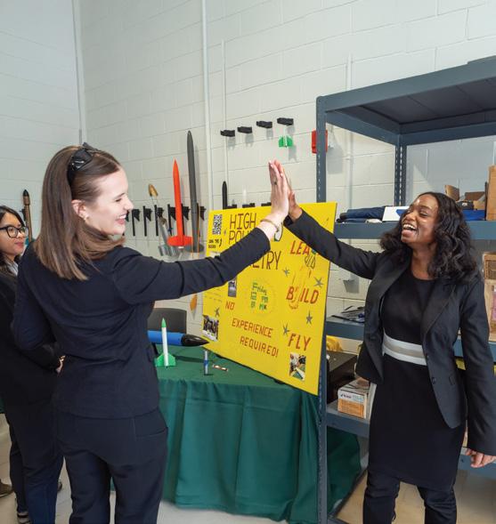
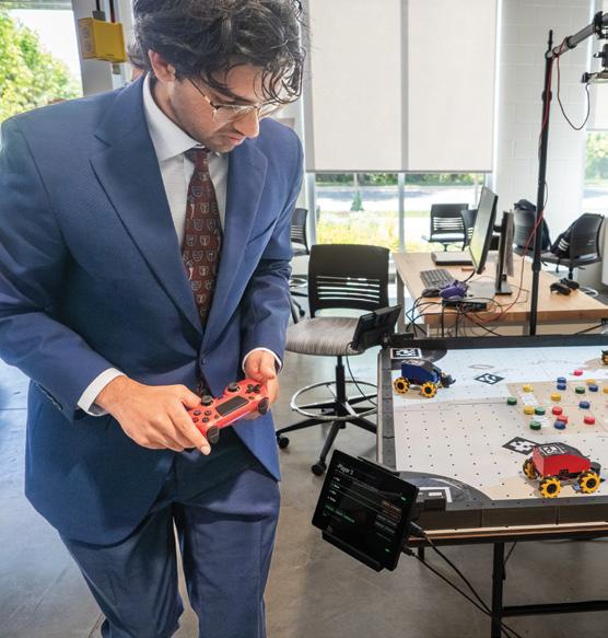
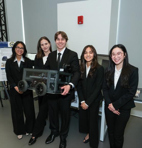
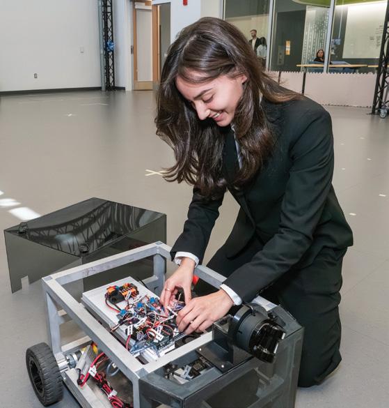
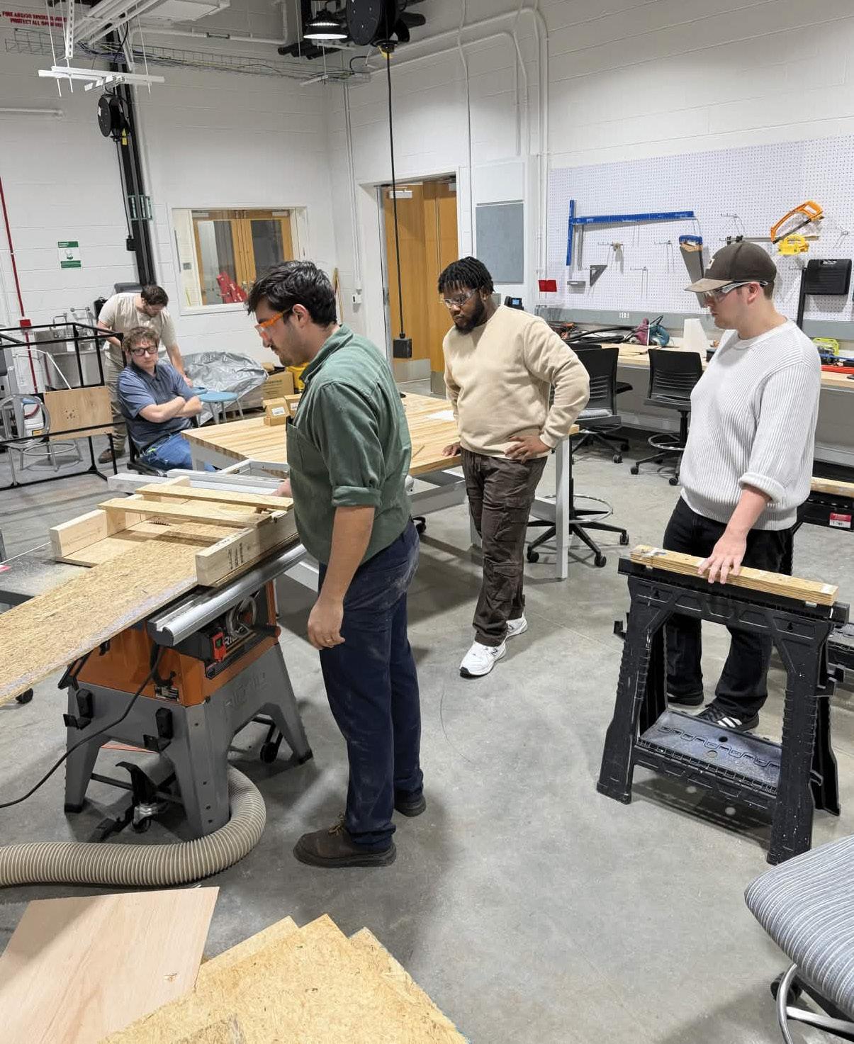
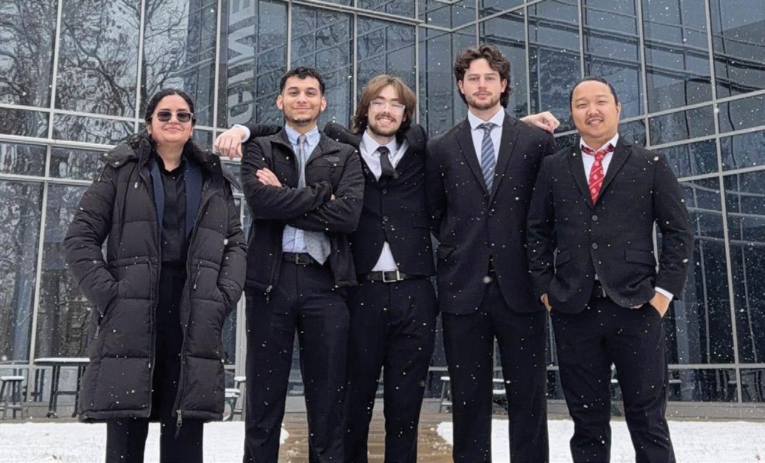
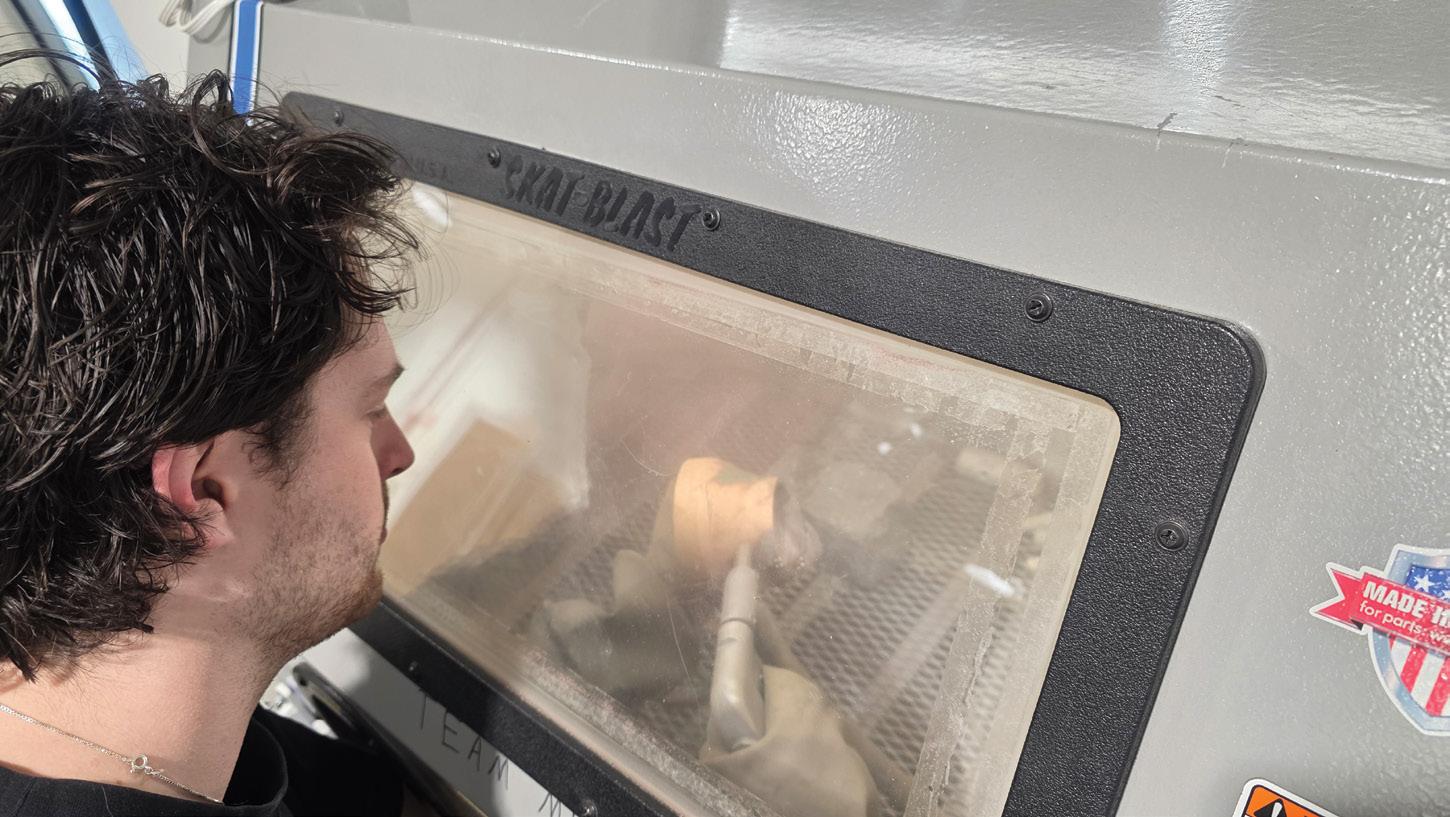
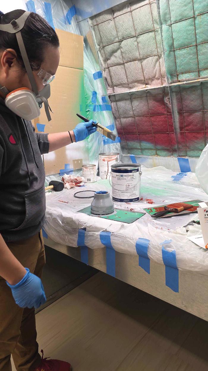
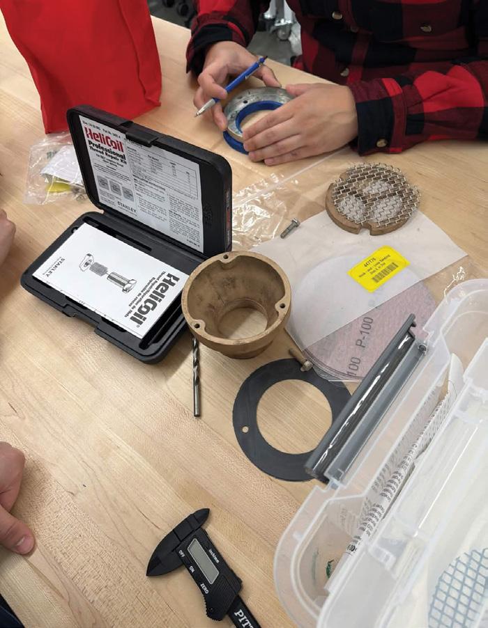
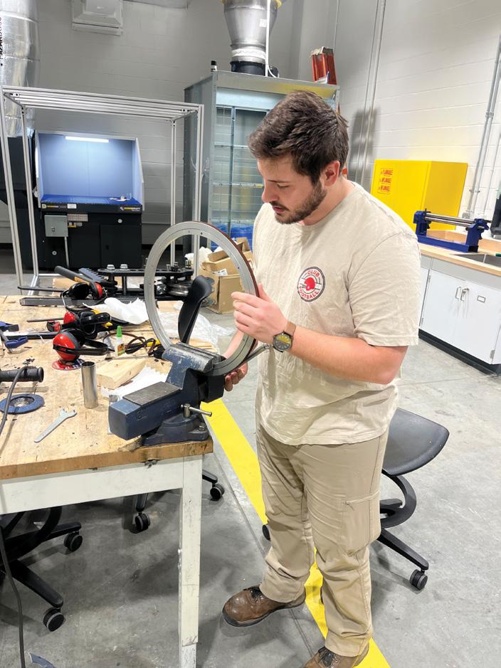
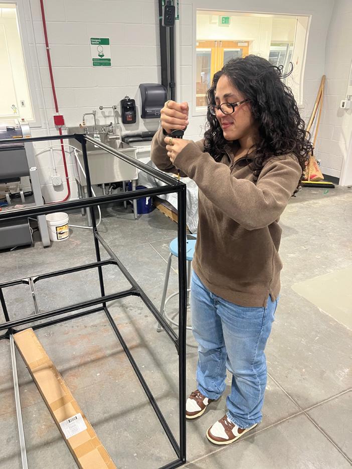
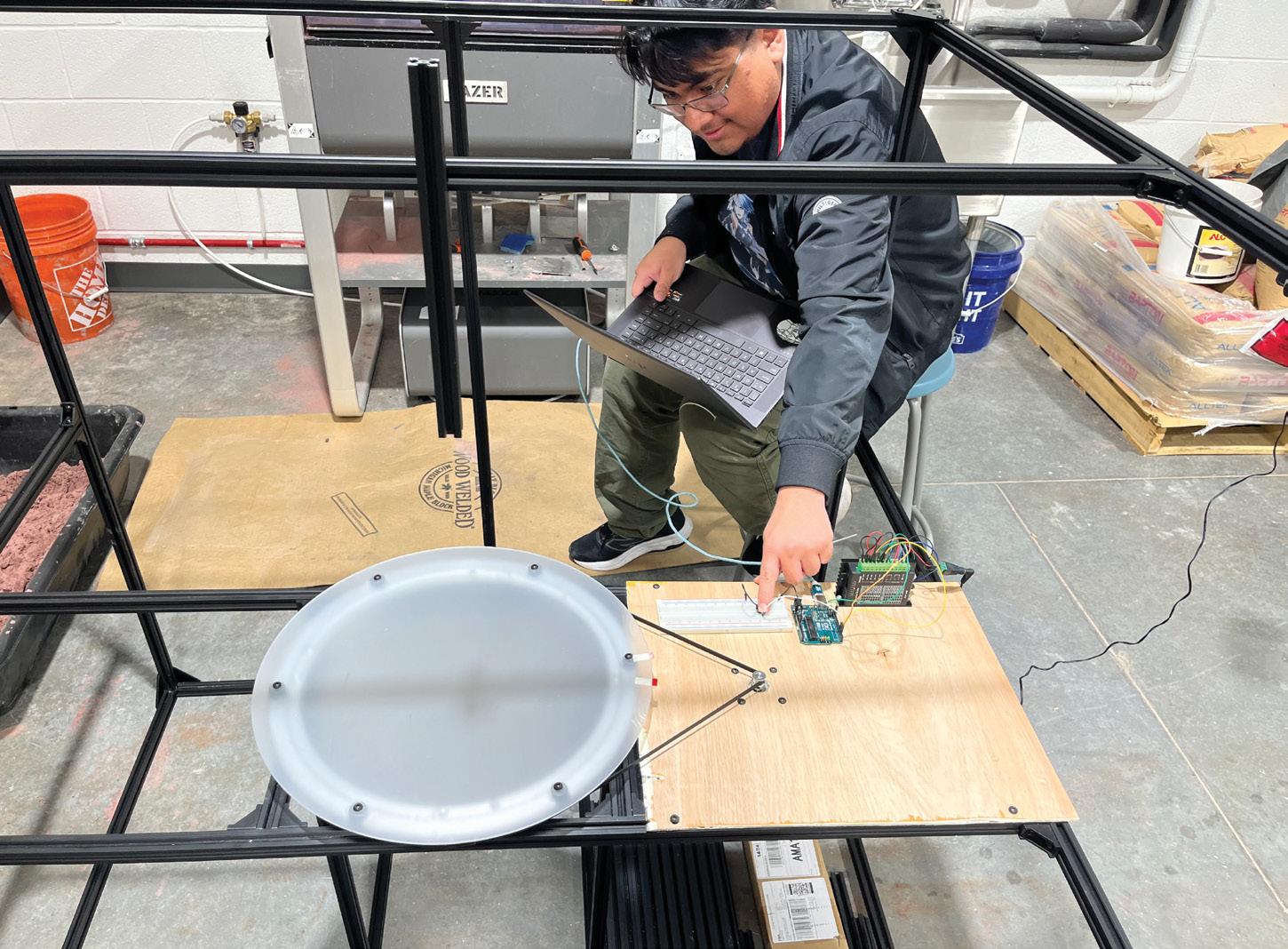
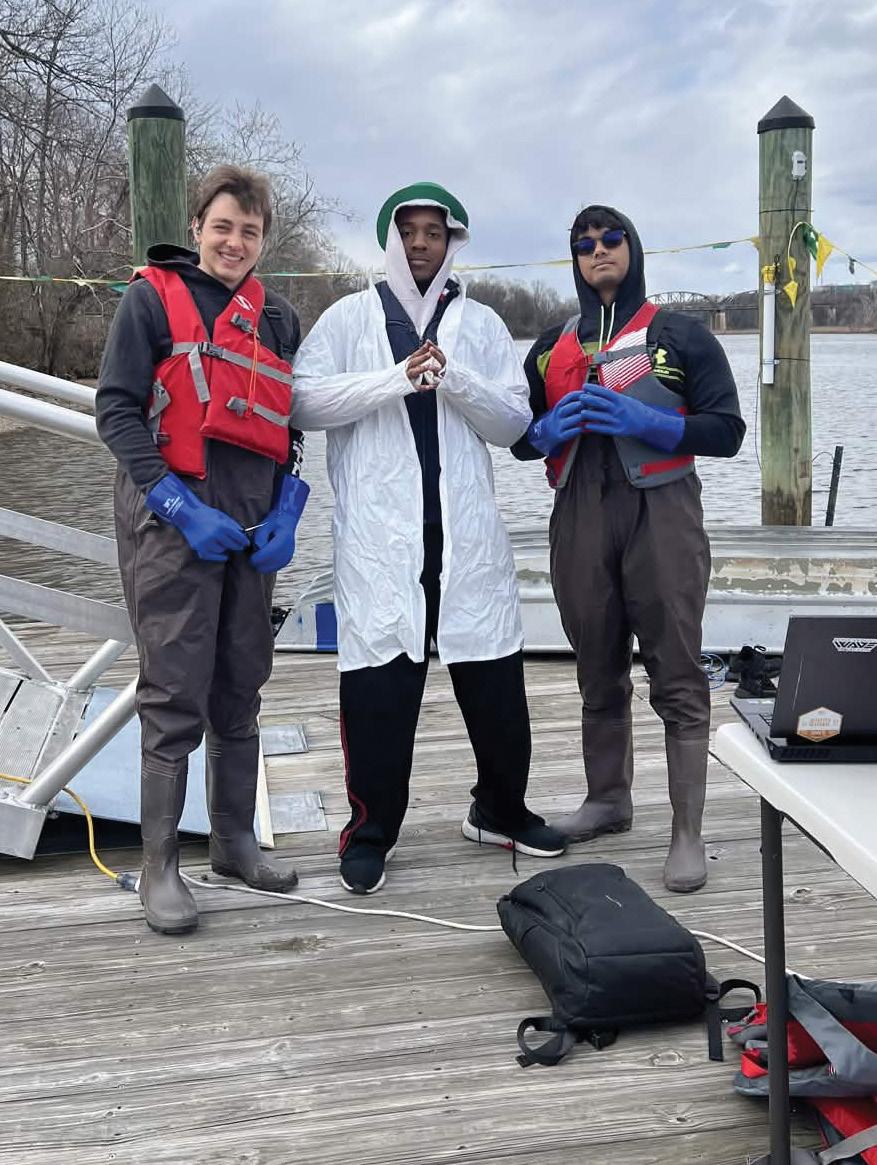
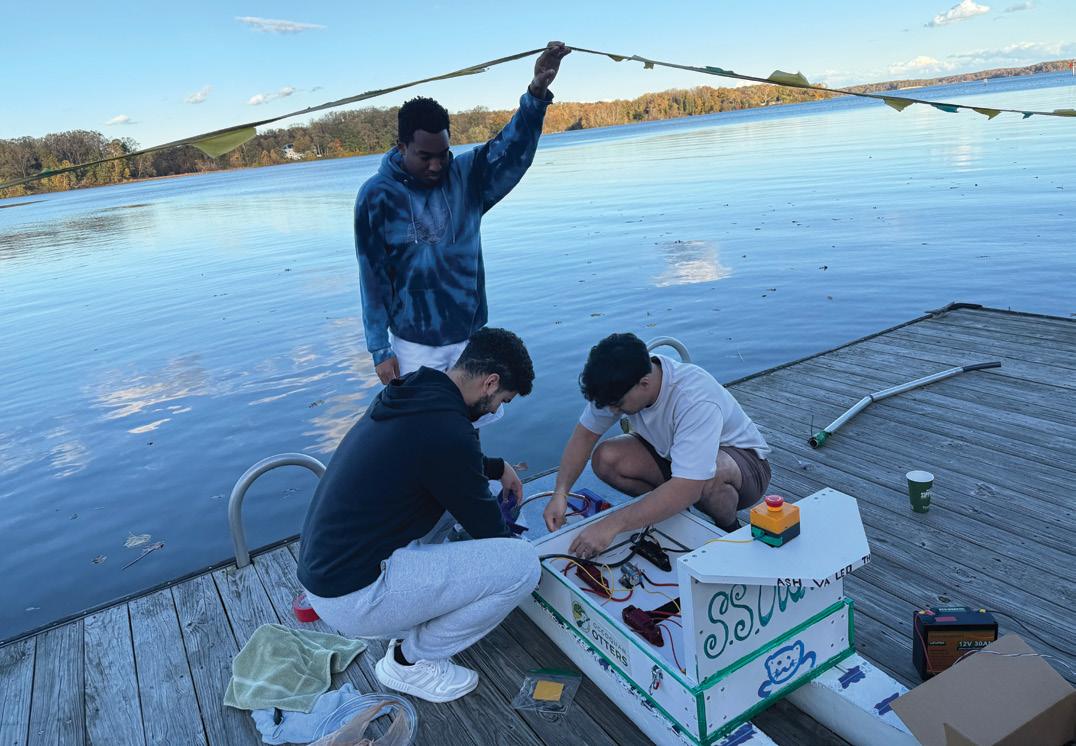
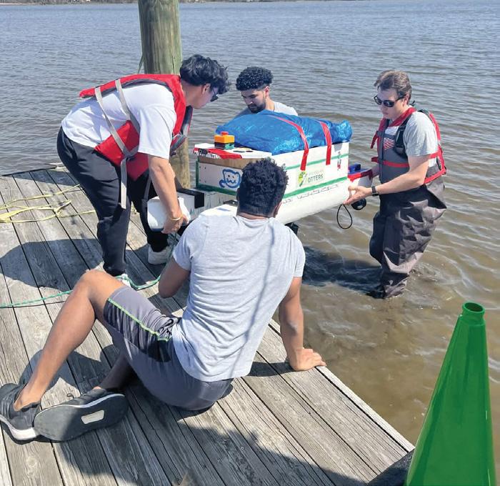
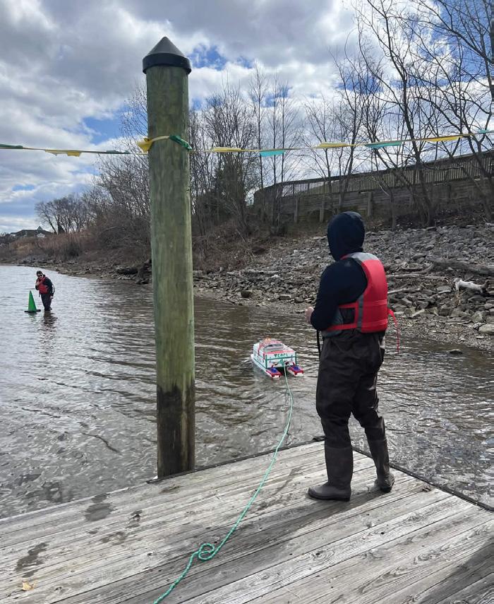
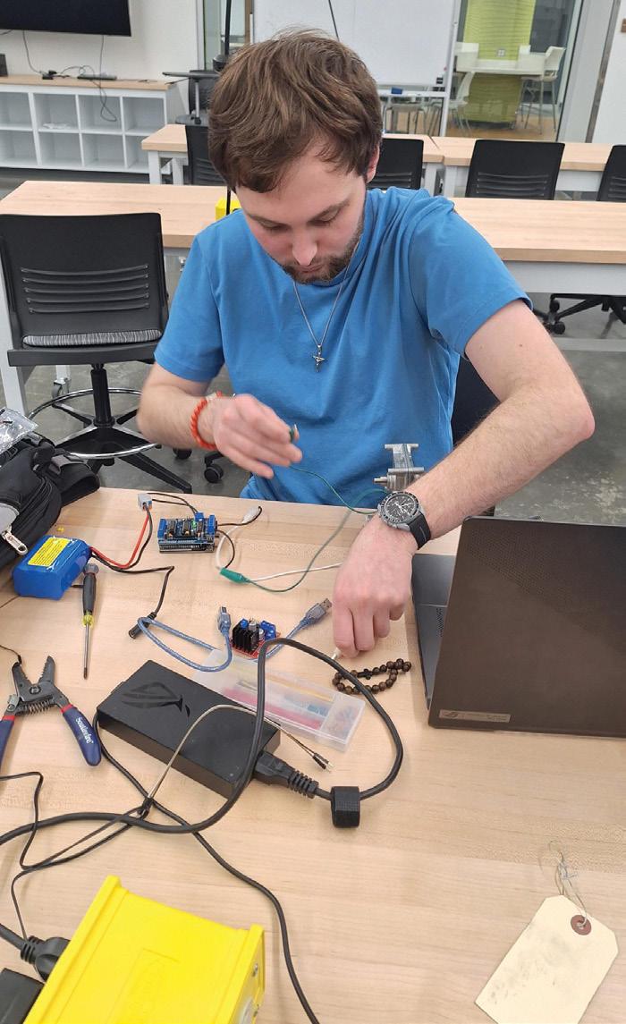
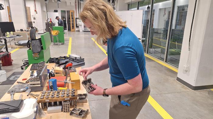
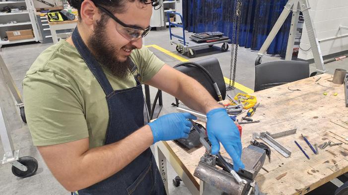
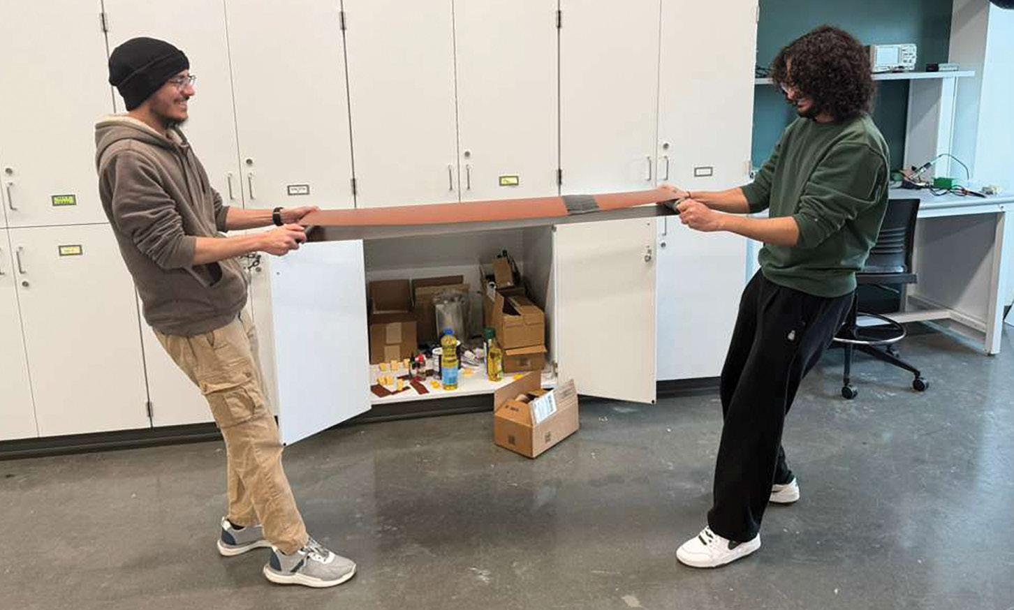
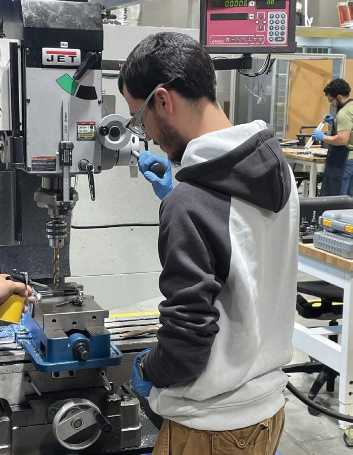
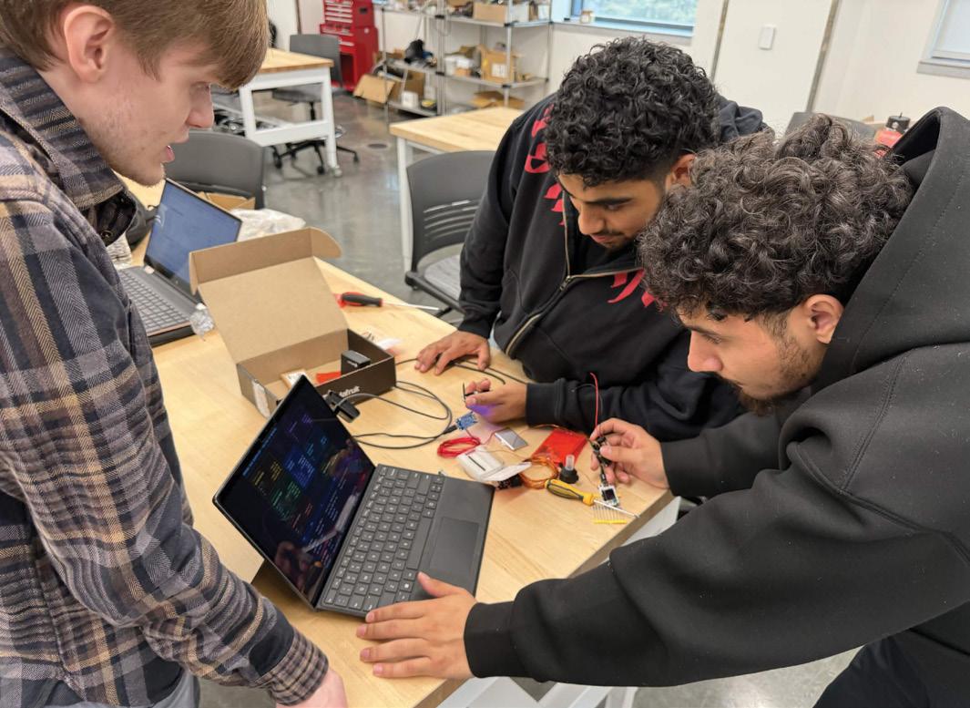
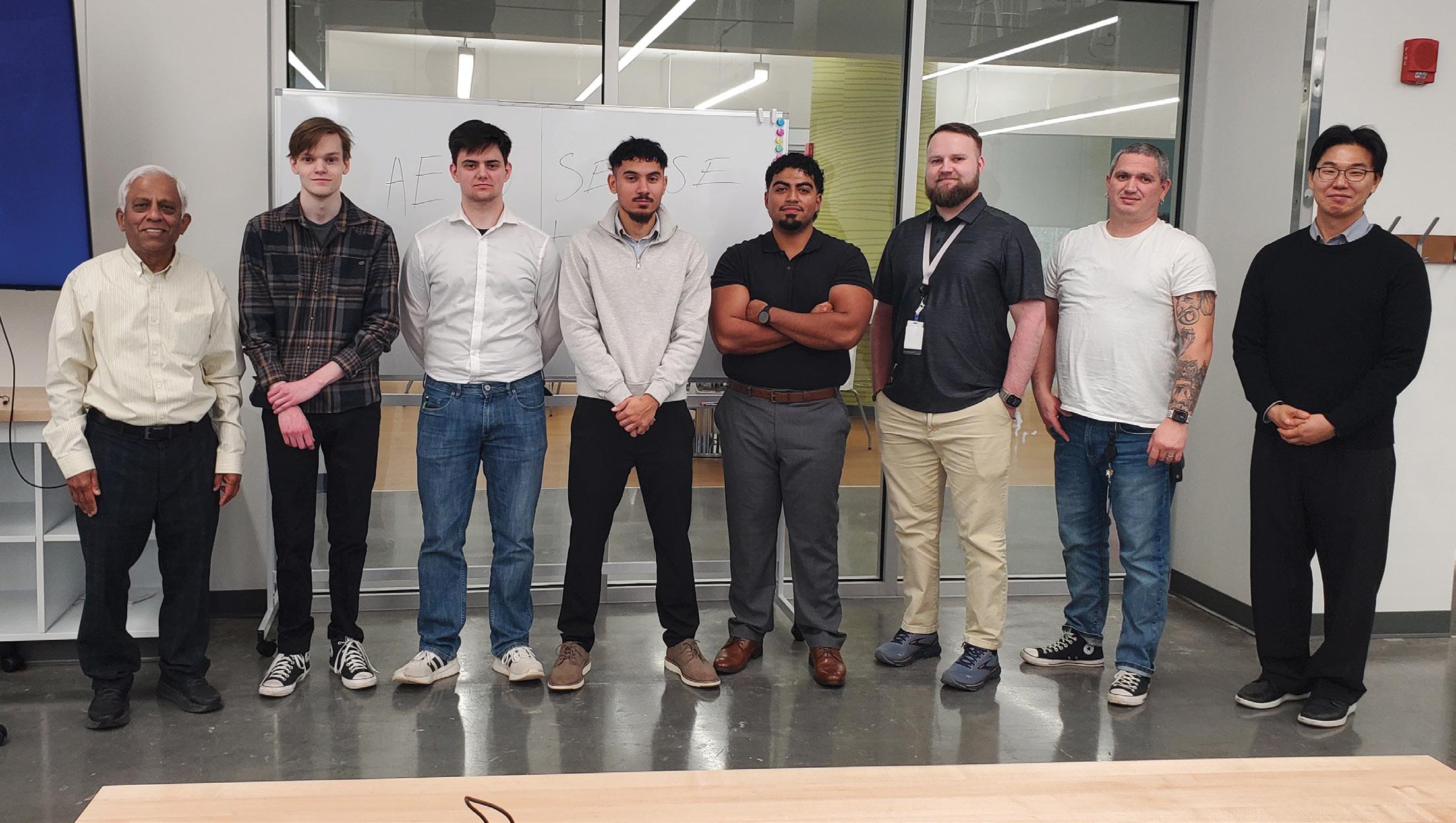
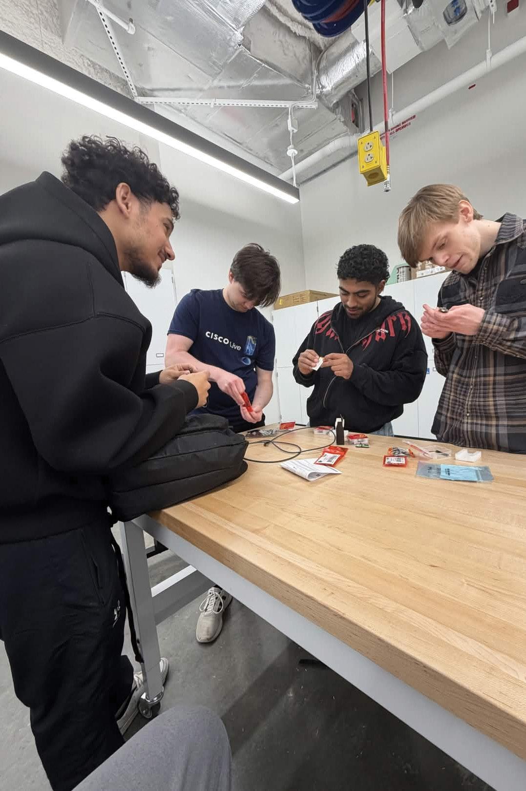
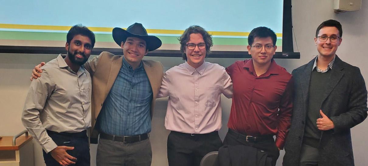
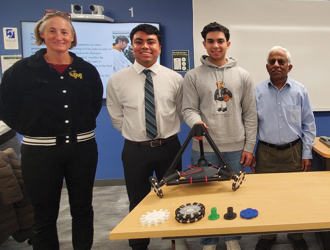
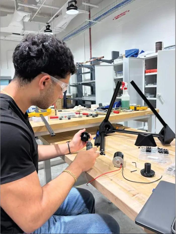
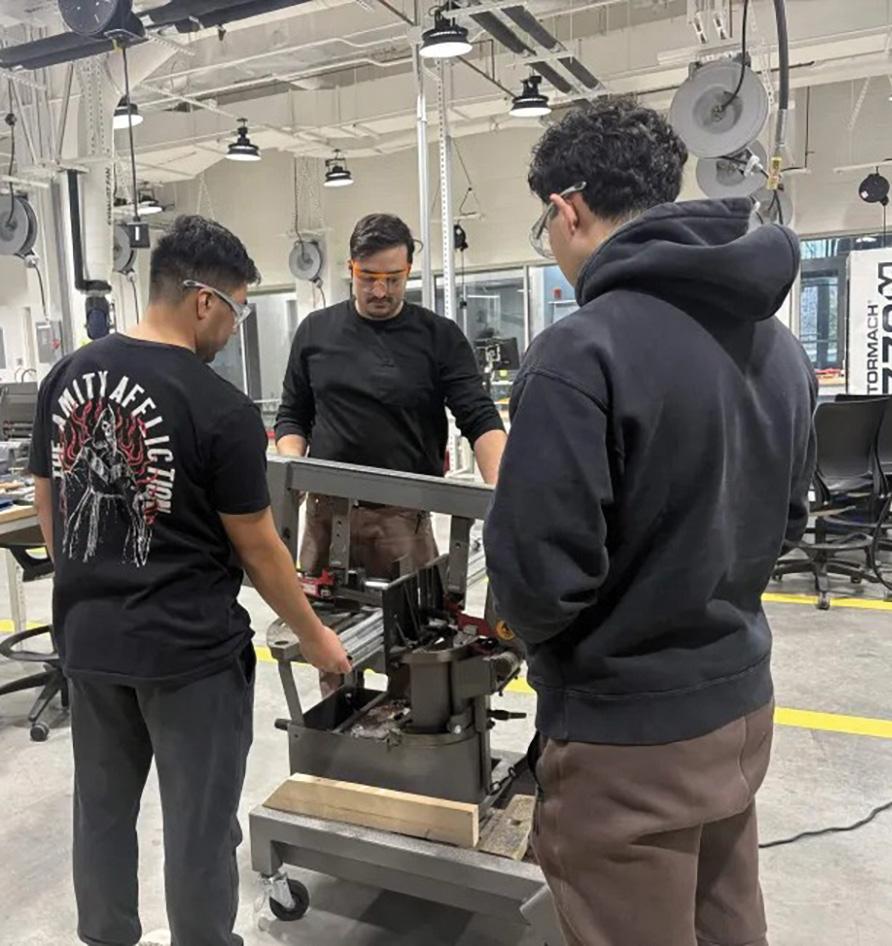
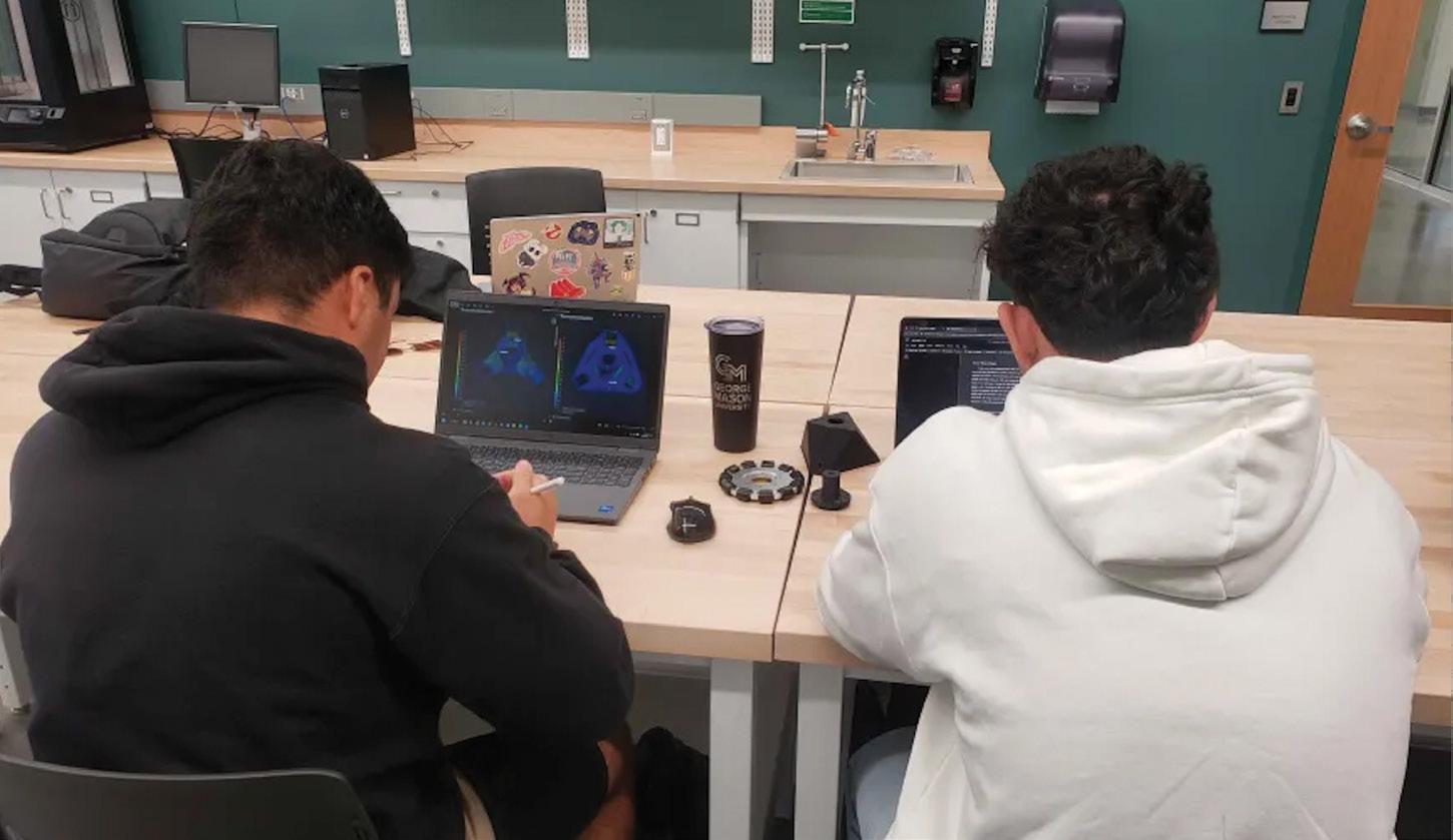
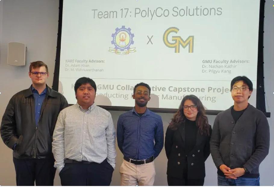
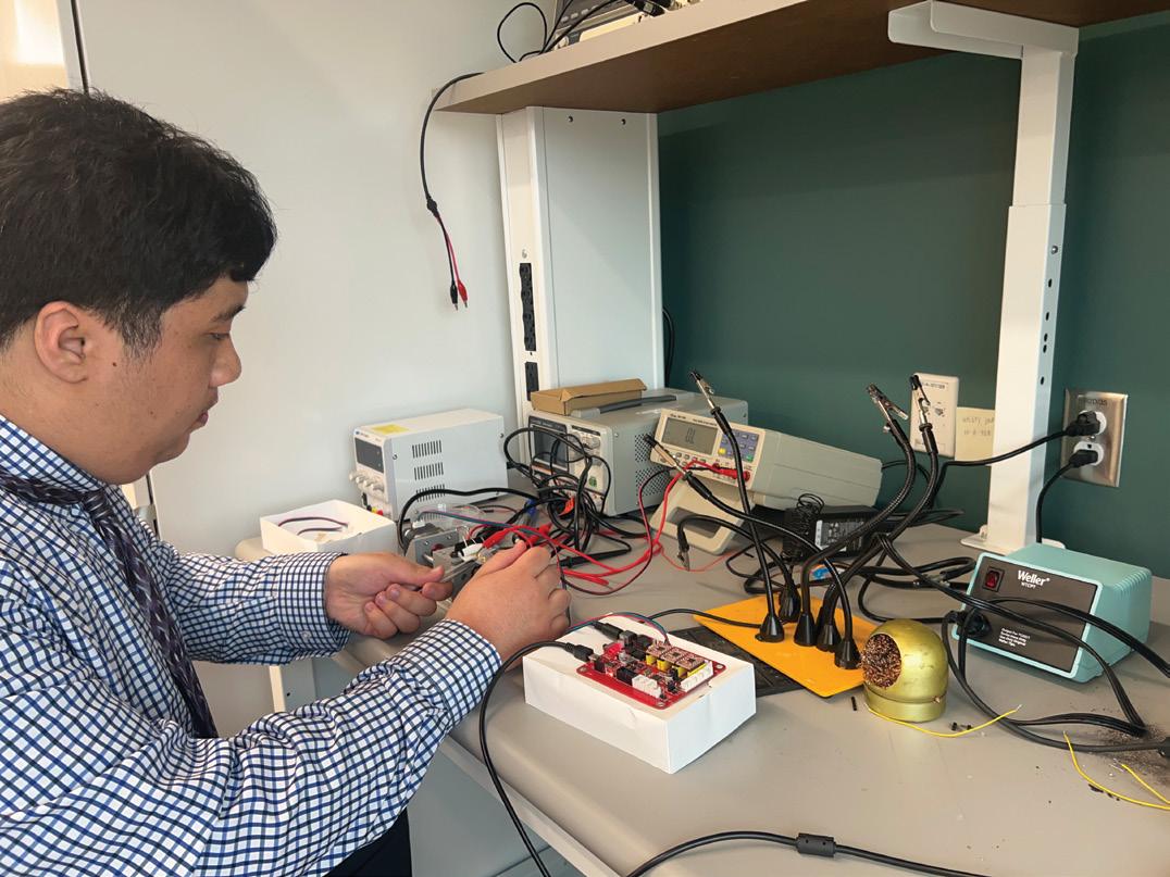
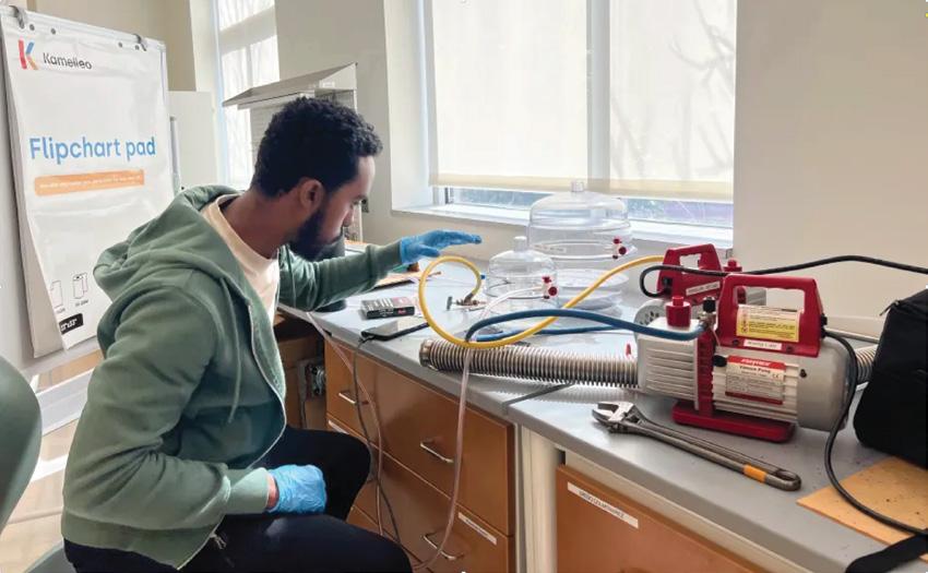
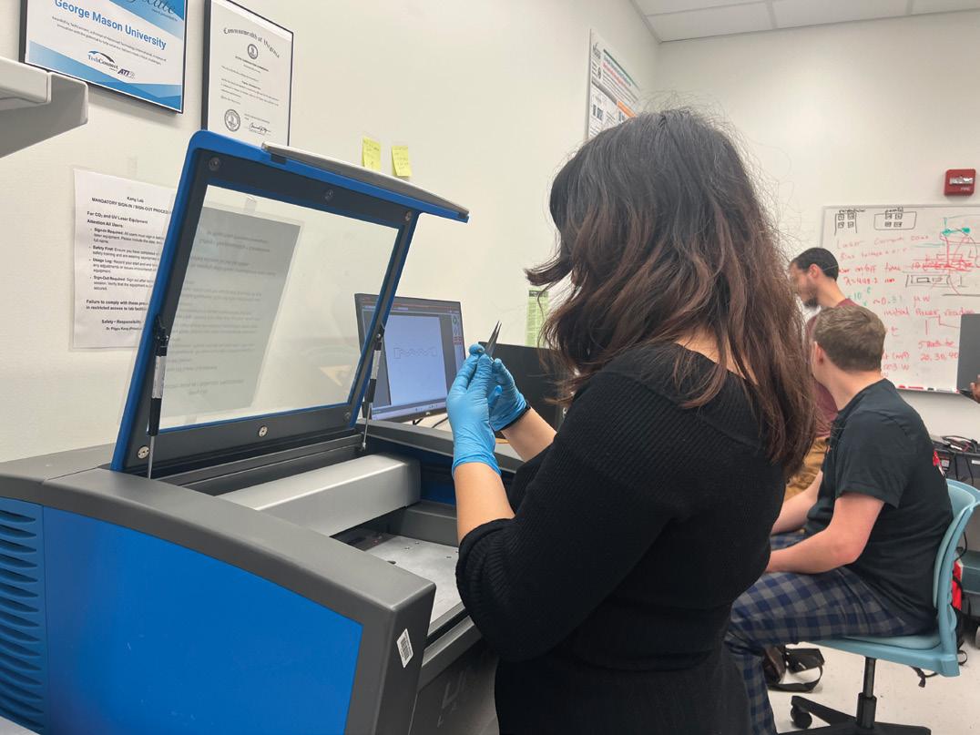
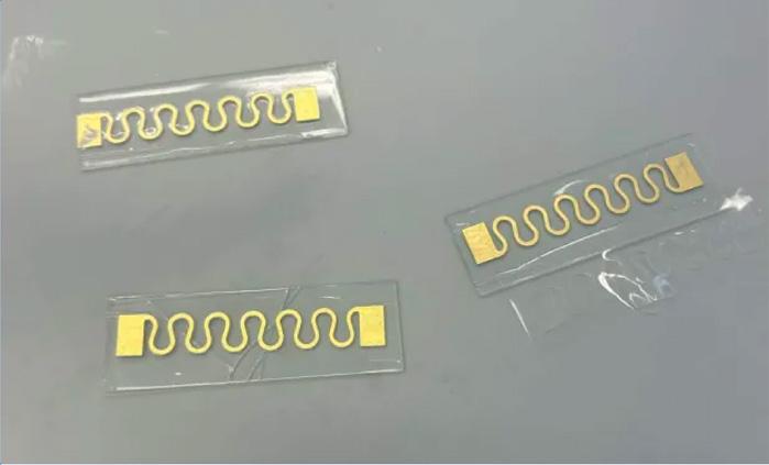
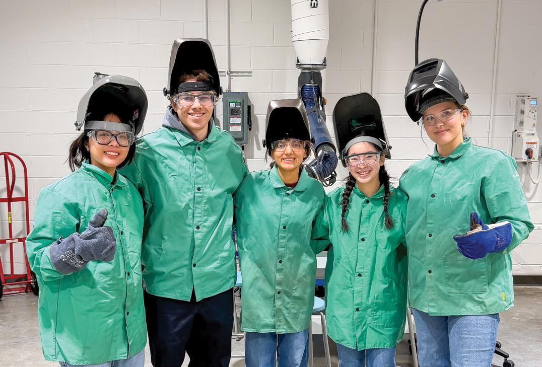
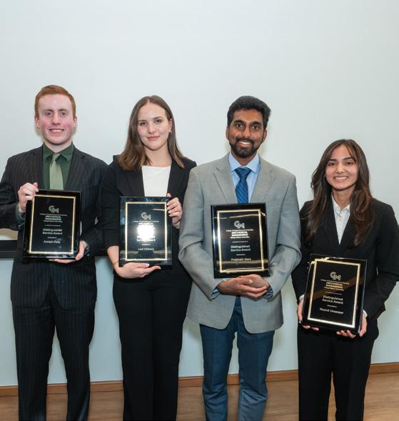
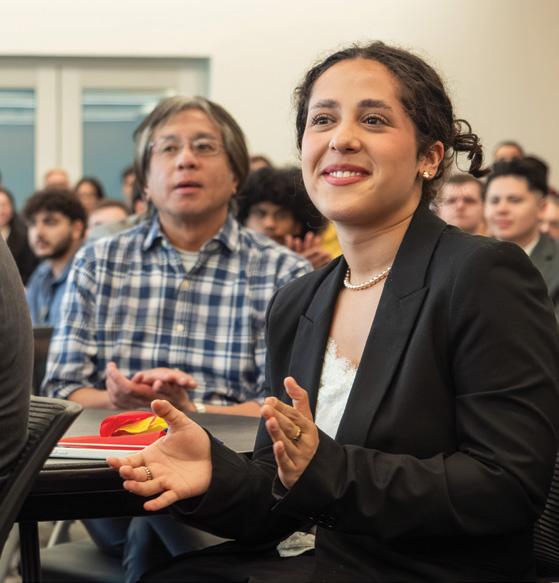
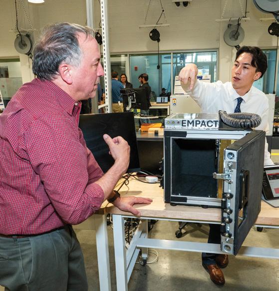
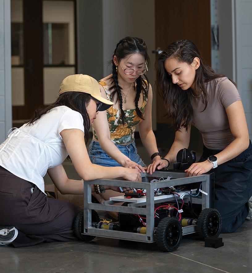
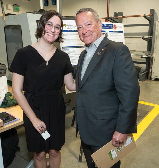
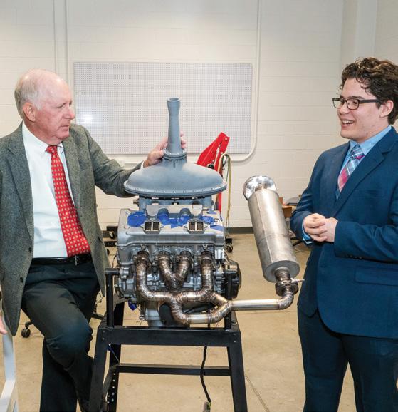
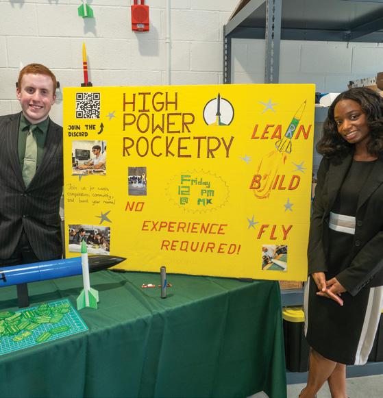
The Capstone program stands as the ultimate showcase of my undergraduate learning. With an emphasis on teamwork, project management, and a hands-on approach, this two-semester project demands that we draw on all aspects of our undergraduate education to succeed. From the beginning of this process, our professors, sponsors, and advisors supported our ambitious goals and prioritized our learning at every step. This project is a great way to leave Mason and this department, as it is a true reflection of the preparation, dedication, and commitment this department invests in students. As a graduating senior, nothing makes me prouder than seeing more than 20 other senior teams successfully complete their project goals.”
—Lexi Chivers
FROM THE ME CLASS OF 2026
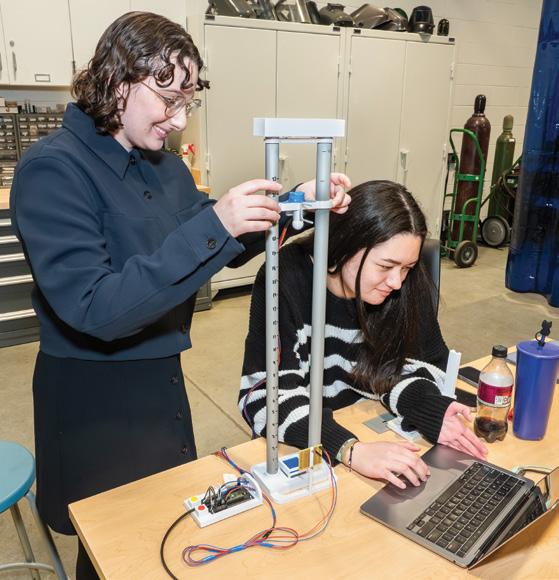
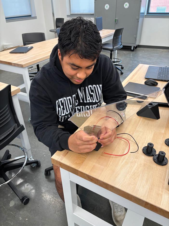
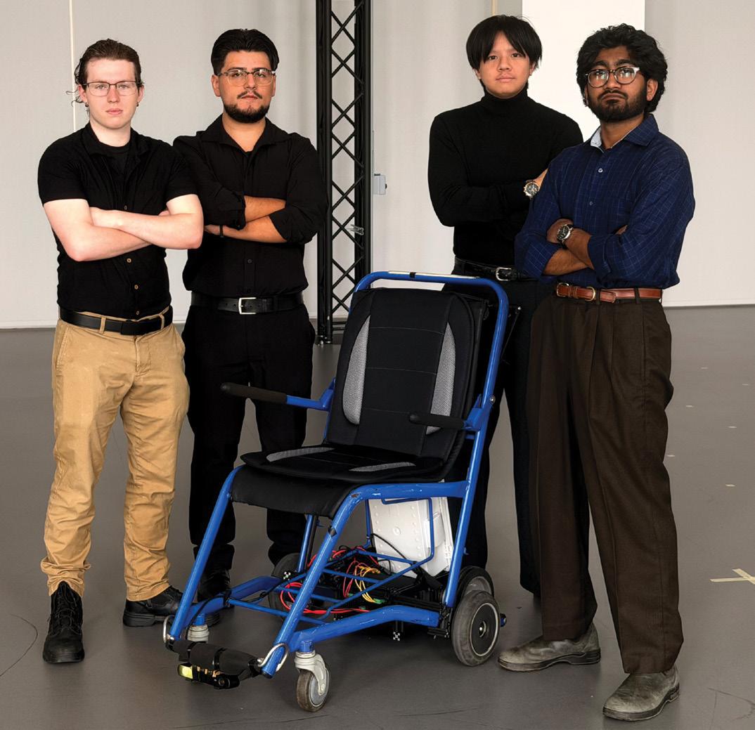
The great thing I learned from the Capstone program is not only the ability to translate core technical skills that we learn in the classroom over our many semesters at Mason into real projects but also translating the soft skills as well. It takes skill to relate Newton’s Laws of Motion and the principles of thermodynamics into a real-life product, but teamwork, communication, and project planning are skills that really make a difference in bringing great ideas to reality, and those can only be sharpened with real experience. The bridge between ideas and reality is what I found to be the true essence of Capstone.”
—Prabhath Gera
Table of Contents
Department of Mechanical Engineering Annual Report
Annual Highlights
George Mason Launches Virginia’s First Robotics PhD
Forged in Passion, Not Just Fire: This Alum Is on a Hot Streak
Printing Play: A Path Forward for Children with Prosthetics
Mechanical Engineering Student Brings World Class Problem Solving to Team USA Cricket
Monitoring Metabolism, Measuring Muscle
9
Cover photo by Evan Cantwell/George Mason University
Leigh McCue
Department of Mechanical Engineering
Professor and Chair
Website
mechanical.gmu.edu
Email
mechengr@gmu.edu
Phone
703-993-5383
Introduction
WELCOME TO OUR 2026 ANNUAL REPORT AND SENIOR DESIGN PROJECT brochure. The 2025-2026 academic year has been another year of growth, with our department’s undergraduate enrollment climbing to 543 students; that’s more than 100 additional students than last year.
Over the summer we received State Council of Higher Education for Virginia (SCHEV) approval to launch the first Robotics PhD program in the Commonwealth of Virginia, and our first students began this year. We welcomed new faculty with Phillip Cunio leading the charge on the expansion of our aerospace programming and Pouya Rezai adding depth of expertise in microfluidics and the intersection of fluids and biological systems. In support of our program growth, we also grew our staff with Josh Dunn joining the machine shop team; Josh has proven to be a great addition with an emphasis on CAD/CAM machining needs. Our academic advisor Sophia Sarver, who has been with us for one year, skillfully took on a larger caseload in support of our increased undergraduate enrollment. This has also been a year for transition as Reem Abdel Khalek, our prior fiscal and budget support specialist, took a growth opportunity elsewhere within Mason and Krista Tran joined us in that fiscal role. As those of you who have been through our capstone program are well aware, the fiscal specialist is a vital team member for the success of that program, and we are fortunate to have Krista on the team.
Through our department’s history, there have been three chairs of the Mechanical Engineering Advisory Board. All three had a noteworthy year with the department. Our first advisory board chair Charles Worrell was recognized by Mason with induction into the College of Engineering and Computing’s Academy of Excellence. Our second advisory board chair Kevin Hicks stepped down from the advisory board for the terrific reason that he joined Mason as a full-time employee. And our third advisory board chair Bruce Andersen stepped up to fill this leadership role in the midst of his own very big year with getting married, moving, and changing jobs!
Nathan Kathir tells me that while last year was our
department’s 10th birthday, this year is our department’s 10th Capstone Day. We have 21 teams this year supported by generous partners at Aeronautical Systems Incorporated (ASI), Amazon Web Services, Chirality Capital Consulting, DidLake, General Dynamics Progeny Systems, Loudoun County Fire and Rescue, Micron Technology, Inc., Naval Surface Warfare Center at Carderock Division (NSWCCD), Nexus234 Innovation District, Office of Naval Research, OmniRide, Patriot Green Fund, Stafford County Fire and Rescue Department, System Innovation, LLC, TTM Technologies, Inc., and Vision Point Systems, Inc., along with registered student organization-led teams for High Power Rocketry, Patriot Motorsports, and RobotX, and teams supported by faculty members Nathan M. Kathir (continuing an international partnership with Kalasalingam Academy of Research and Education), Daigo Shishika, and Tolga Soyata (Department of Electrical and Computer Engineering).
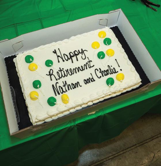
Perhaps the biggest news for the department this year is bittersweet in that Professors Kathir and White are both retiring at the end of the academic year. Both have been tremendous contributors to the department at large and the capstone program in particular. Their vision, leadership, and student-success focused mindset have set a wonderful tone for the department which we will be sure to lean into as they enjoy quality time with family in their well-deserved retirements. To see a bit more about their impact on the program, please flip to page 64.
To those of you who are celebrating your forthcoming graduation this Capstone Day, congratulations! We can’t wait to celebrate your successes as you enter the mechanical engineering workforce. Please consider this a standing invitation to return each Capstone Day, be a guest in our classes, or invite current students to tour where you’ve landed. It is our great joy when we can see you thrive and continue to foster your connections here at your alma mater George Mason University. Cheers!
Department by the Numbers
■ Information Technology—Mechanical Engineering PhD Students
■ Naval Ship Design Graduate Certificate
■ Computer Science PhD Students
■ Electrical and Computer Engineering PhD Students
■ Systems Engineering and Operations Research PhD Students
■ Bioengineering PhD Students
■ College of Science PhD Students
■ Engineering Physics MS/PhD Students
■ Robotics PhD Students
DEPARTMENT OF MECHANICAL
ENGINEERING
Annual Report
Faculty Profiles
FACULTY WITH SENIOR LEADERSHIP ROLES
Kenneth Ball
Dean, College of Engineering and Computing, and Professor Areas of expertise
Thermal and Fluid Science Research interest
Computational Fluid Dynamics and Heat Transfer
Colleen Berg Instructor and Associate Chair for Undergraduate Programs
Areas of expertise
Robotics and Control
Andre W. Marshall
Vice President, Research, Innovation, and Economic Impact and Professor Areas of expertise
Thermal and Fluid Science Research interest
Experimental/Computational Evaluation of Complex Turbulent Reacting Flows and Sprays
TEACHING-FOCUSED FACULTY
Zelalem Eshete Assistant Professor Areas of expertise
Materials, Mechanics, and Manufacturing
Saanyol Ityokumbul Igbax Assistant Professor Areas of expertise
Thermal and Fluid Science; Energy and Power Plant Engineering
Gregory Washington University President and Professor Areas of expertise
Robotics and Control Research interest
Modeling and Control of Smart Material Structures and Systems
Nathan M. Kathir Professor and Director of Senior Projects Areas of expertise
Materials, Mechanics, and Structures; Critical Infrastructure
Charles White
Associate Professor Areas of expertise
Materials, Mechanics, and Manufacturing
Mehdi Amiri
Assistant Professor
Areas of expertise
Mechanics, Materials, and Manufacturing
Research interest
Fatigue/Fracture Mechanics, Corrosion, Experimental and Computational Mechanics
Phillip M. Cunio
Professor of Practice
Areas of expertise
Robotics and Control; Design, Optimization and Entrepreneurship
Research interest
Aerospace, Space Vehicle Design, Space Situational Awareness, Planetary Surface Exploration
Jeffrey L. Moran
Associate Professor and Associate Chair for Graduate Studies
Areas of expertise
Thermal and Fluid Science; Mechanics, Materials, and Manufacturing
Research interest
Active Matter, Fluid Mechanics, Electrokinetics, Heat Transfer, Transport Phenomena
RESEARCH-FOCUSED FACULTY
Shaghayegh “Shay” Bagheri
Assistant Professor
Areas of expertise
Mechanics, Materials, and Manufacturing
Research interest
Additive Manufacturing, Composites, Biomechanical and Biomaterials
Pei Dong
Associate Professor
Areas of expertise
Mechanics, Materials, and Manufacturing
Research interest
Carbon Materials, Polymers, Self-Adaptive Materials, Water Treatment, Batteries, Solar Cells, Biosensors
Pouya Rezai
Associate Professor
Areas of expertise
Thermal and Fluid Science
Research interest
Microfluidics, Lab-on-aChip, Sensors, Point of Need Detection
Ali Beheshti
Assistant Professor and Associate Chair for Research
Areas of expertise
Mechanics, Materials, and Manufacturing; Design, Optimization, Entrepreneurship
Robotics and Control, Autonomous Systems, Multi-agent Systems, Cooperative Control
Mary “Missy”
Cummings Professor
(Joint Appointment with ECE and CS)
Areas of expertise
Robotics and Control
Research interest
Human-unmanned vehicle interaction, Humanautonomous system collaboration, Robotics and artificial intelligence
Leigh McCue
Professor and Department Chair
Areas of expertise
Thermal and Fluid Science; Robotics and Control Research interest
Ship Dynamics, Hydrodynamics, Autonomous Vessels, Occupational Safety and Health
Janis Terpenny
Professor (Joint Appointment with SEOR)
Areas of expertise
Design, Optimization, Entrepreneurship
Research interest
Engineering Design, Systems Engineering, Smart Manufacturing, Engineering Education
TENURE TRACK/TENURED FACULTY RESEARCH FOCUS AREAS
Our research focus areas cover broad applications including:
◆ Aerospace
◆ Advanced and Smart Manufacturing
Design, Optimization, and Entrepreneurship
◆ Automation ◆ Water Treatment ◆ Health Care ◆ Energy
Defense
Naval Engineering
Mechanics, Materials, and Manufacturing
◆ Sustainability and Reliability ◆ and more
Tim Diggins Administrative Specialist
Josh Dunn LSEB Instructional Technician
Johnnie Hall, IV Machine Shop Manager
Philip Payne Machinist
Sophia Sarver Academic Advisor
Krista Tran Fiscal and Budget Support Specialist
George Mason Launches Virginia’s First Robotics PhD
GEORGE MASON UNIVERSITY’S DEPARTMENT OF MECHANICAL ENGINEERING is leading the way in robotics with the approval of Virginia’s first PhD program in robotics. On July 10, the State Council of Higher Education for Virginia (SCHEV) officially approved the trailblazing program that will educate future leaders in the growing field.
Mechanical Engineering Department Chair Leigh McCue and leading robotics faculty across the College of Engineering and Computing combined forces to create the multidisciplinary program that spans mechanical engineering, electrical and computer engineering, computer science, and cybersecurity.
“George Mason is a powerhouse in robotics,” says McCue. With more than 30 faculty members in the field, numerous labs, and research projects, students in the program have access to countless opportunities.
The approval for this program was years in the making and involved many faculty, and it’s coming at the right time to make an impact. “With faculty like Missy
Cummings, who will be the program director, Cameron Nowzari, Quentin Sanders, Daigo Shishika, Ningshi Yao, and many more, plus our centers and labs that span across all of our northern Virginia campuses, it felt like the time was right to put together a multidisciplinary program that brings together many great researchers,” says McCue.
The new labs in the Mason Autonomy and Robotics Center (MARC) in Fairfax, the Life Sciences and Engineering Building on the SciTech Campus, and Fuse at Mason Square in Arlington increase the college’s capabilities by providing state-of-the-art areas for designing and constructing any robotic system students and faculty envision, enhancing research and teaching activities.
MARC, which opened in spring 2024, is already pioneering designing secure and intelligent autonomous systems. “Every robotics PhD student has a home in MARC. Like the program, it spans expertise across the College of Engineering and Computing and other colleges throughout the university,” says Missy Cummings, PhD program director and co-director of MARC.
As the program grows, Cummings, McCue, and Jeffrey Moran, Mechanical Engineering’s associate chair for graduate studies, hope to see more partnerships and opportunities for these students. “I hope to see the types of projects diversify over the next ten years. Robotics is everywhere, and it touches so many industries, so I would like to see us break into new research areas, such as medical robots or micro-robotics,” says Moran.
Cummings adds that they are looking to partner with other universities and colleges across the state to support this growth and access to research in robotics.
The program began accepting transfer students in fall 2025. The department’s decision to fast-track the launch reflects high student interest and strong faculty readiness. “We have the talent, the infrastructure, and a clear vision,” says McCue. “ This program is ready to go.”
Students at work in the new robotics makerspace in Fuse at Mason Square. Photo by Ron Aira/Office of University Branding
Forged in Passion, Not Just Fire: This Alum Is on a Hot Streak
KEEPING HIS NOSE TO THE GRINDSTONE is not just how Andrew Hutsell approaches his academic career in engineering—it’s how he cut a small slice of fame.
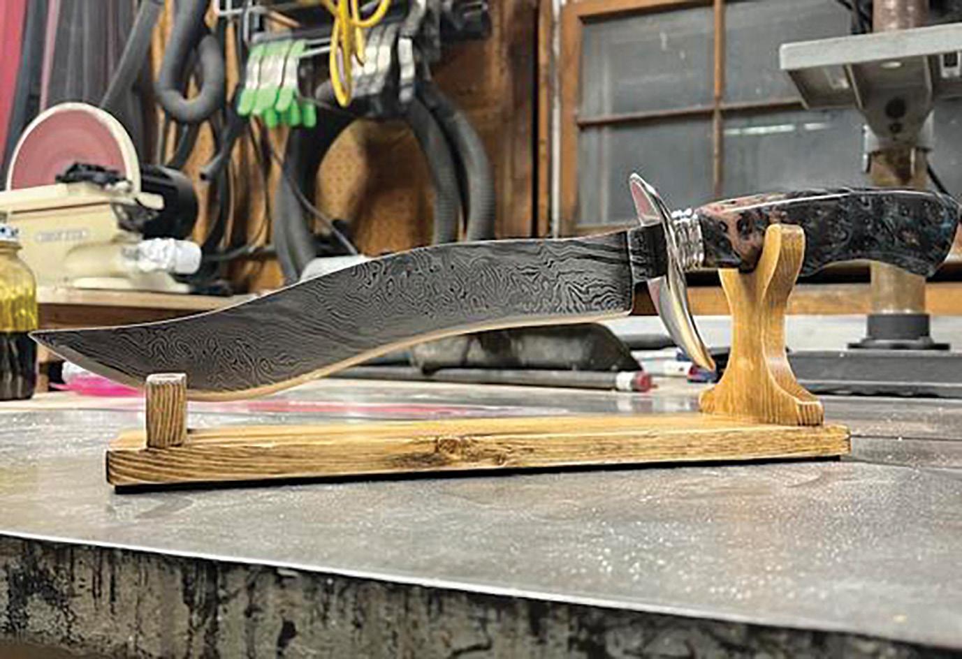
The George Mason University alumnus recently put his engineering skills to the test on national television, competing in an episode of the History Channel’s Forged in Fire, a competition show that challenges bladesmiths to create weapons under tight deadlines. Hutsell has been a fan of the show since 2016 and started bladesmithing in 2019.
Hutsell, BS Mechanical Engineering ’23, appeared on the episode “Junkyard Meltdown” on September 17 (S10E27).
Hutsell’s journey began when one of the show’s judges posted a casting call on Instagram. “I was still a student at the time, so they asked what I do at George Mason, what I do in my free time, and to provide examples of the knives I’ve made,” said Hutsell, who also was president of George Mason’s club baseball.
“Ever since I started making knives, I have only had one goal with each knife I make: learn at least one new skill or method [for the trade]. With this mindset, it is easy to see how my skills have improved over time,” said Hutsell.
After multiple rounds of interviews, he got the call to appear during a midterm exam. Filming took place in March and April 2023. Hutsell described the show’s format as similar to Chopped, but instead of cooking, contestants forge knives through three rounds of competition.
For the last round, judges pick a historical weapon, such as a broad sword or katana, and then contestants go back to their hometown to forge it with their own equipment.
“I traveled back home to Newport News. When I came back, they tested it to determine the winner,” said Hutsell. “They tested the knives by chopping through bone for strength, then slicing sugar cane to see how well the edge held up. It was surreal to compete on a
show I’d watched for years,” said Hutsell, who came in second place.
Hutsell is currently a graduate student at Virginia Commonwealth University working on similar topics such as fluids research. “The research that I’m doing is for thermal hydraulics—the cooling system—of molten salt [nuclear] reactors, researching the gas sparring of fission products of molten salts for molten salt reactors,” said Hutsell.
Hutsell was influenced by Jeffrey Moran, an associate professor in the Department of Mechanical Engineering, who Hutsell describes as a “a big influence on my work with heat and mass transfer,” as well as Juan Cebral, an associate professor in the Department of Bioengineering.
“It is always very rewarding when a student demonstrates this passion for learning and dedicates substantial time and effort to master the material to reach high levels of achievement,” said Cebral. “Andrew was one of those students who is dedicated to solving complex problems. His perseverance and motivation will certainly help him make important contributions in his field.”
One of Andrew Hutsell’s knives.
Printing Play: A Path Forward for Children with Prosthetics
A CHILD WHO USES A LOWER-LIMB PROSTHESIS faces unique challenges when it comes to activities most children take for granted, such as running and being active. Without access to a prosthetic device designed to support these movements, children may miss out not only on the simple joys of play, but also on critical opportunities for physical development during key stages of growth.
George Mason University researcher Quentin Sanders is part of a collaborative research team working to make high-performance prosthetic limbs more affordable, accessible, and better tailored to the needs of active children. Sanders, along with Jonathon Schofield, an associate professor at the University of California, Davis, and Garrett Melenka, an associate professor at York University, received a three-year, $500,000 grant from the National Science Foundation to support the project, which began in September 2025. Most standard foot or leg prostheses are built for basic walking, not for the kind of active movement that helps children develop strength, balance, and coordination, the benefits that come from running and jumping with friends.
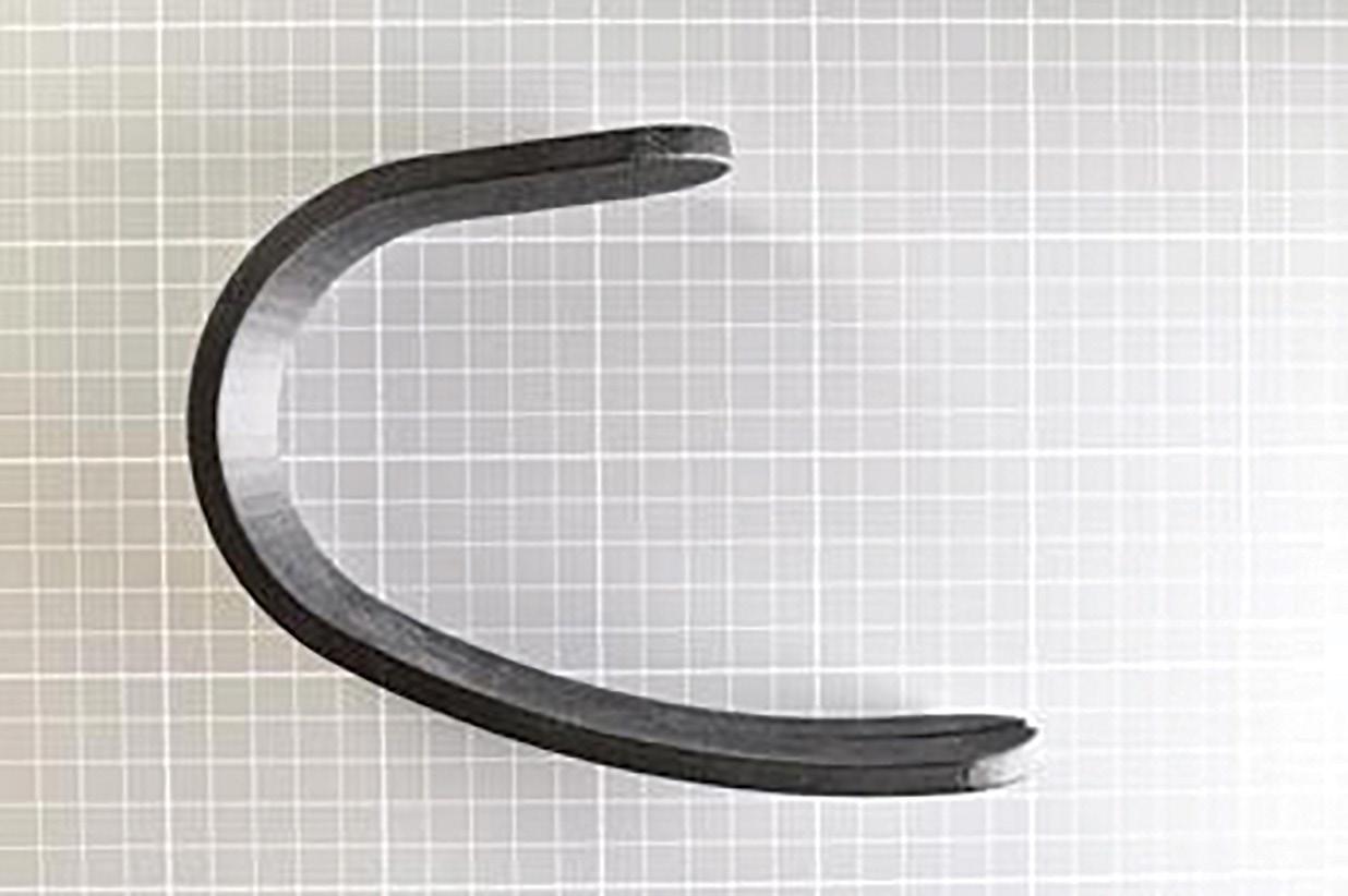
Often seen in competitive events such as the Paralympic Games, running blades are curved, springlike prosthetic feet made from carbon fiber that mimic the energy return of a biological foot. While these devices offer an alternative option to standard leg prostheses and can enable children to run, they are expensive and often inaccessible.
The research team has several goals, starting with identifying what children truly need from an activityenabling prosthesis. The researchers are examining how motivation to be active, physical growth, and different types of movement influence prosthetic performance in everyday settings. “What do you use it for? What don’t you use it for? What do you wish you could do?” said Sanders.
The team is also analyzing how children move while using their current running blades, studying activities such as running, jumping, and changing direction to better understand the biomechanics and physical demands involved.
Finally, the team will take a close look at how today’s running blades perform under real-world demands. “We want to understand how stiff they are, how much load they can handle, and when they might fail,” said Sanders. “We can then combine that information with what kids tell us they want to do and use it to guide our 3D printing process—creating blades that are better suited for active play.”
Sanders and his collaborators are using an advanced additive manufacturing approach known as continuousfiber 3D printing, in which carbon fibers are embedded within the printed plastic to reinforce the prosthetic structure. This method enables the creation of strong, lightweight devices that can be tailored to a child’s size, growth, and activity needs.
The technique is already used to produce strong, lightweight components in the aerospace and automotive industries, but it has seen limited adoption in prosthetic design. This project represents one of the first efforts to apply it systematically to activity-enabling prostheses for children.
A 3D-printed running blade prototype, created using the technique Sanders and his colleagues are developing.
Mechanical Engineering Student Brings World Class Problem
Solving to Team USA Cricket
IN A MUST-WIN MATCH DURING THE T20 WORLD CUP GLOBAL QUALIFIERS , the U.S. Women’s National Cricket Team needed composure, strategy, and execution under pressure. Sophomore mechanical engineering major Lekha Shetty brought all three, drawing on the same problemsolving mindset she uses at George Mason University.
A pace bowler—cricket’s version of baseball’s pitcher—for Team USA, Shetty took three wickets while conceding just 29 runs, a dominant performance that earned her Player of the Match and pushed the United States into the Super Six round, keeping the team’s World Cup hopes alive.
For Shetty, that success reflects the same analytical approach she brings to mechanical engineering coursework in George Mason’s College of Engineering and Computing.
As a bowler, Shetty constantly evaluates conditions, adjusts strategy, and adapts in real time—skills that closely mirror engineering problemsolving. “I’m kind of like the person who figures out what I want to do, or how to solve the problem,” she said. “You’re always trying to figure out how to get the batter out. You can’t just bowl the same ball over and over again. You need to have a little bit of variation.”
Shetty was first introduced to cricket at age 12 after attending a free trial session with a friend. What began as a casual interest quickly turned into a serious commitment, marked by early mornings and disciplined training. Reflecting on her high school years, she recalled, “Waking up at 5 a.m. to go to practice, a lot of those days I did not want to get up, but I’m so happy that I did. Because it’s gotten me to this position.”
That discipline now defines both her athletic and academic life. Shetty is currently pursuing a degree in mechanical engineering while competing internationally with Team USA, a balance that demands careful time management and focus. “I practice at least five times a week,” she said. “That’s like two hours almost every day, and then on top of that, you need to keep in shape. Then the rest of the time it’s college or homework, or I’m eating my lunch or breakfast in the car.”
Shetty’s ability to manage time, think strategically, and perform under pressure underpins her success in both arenas. She was drawn to mechanical engineering through a CAD design class and a love of finding innovative solutions. On the field, she analyzes batters and adapts tactics. In the classroom, she applies that same analytical framework to engineering challenges.
She credits George Mason faculty with helping make that balance possible. “The professors are great,” she said. “They’re thankfully very understanding of my situation.”
With cricket set to appear in the 2028 Olympics, Shetty remains focused on growth in both her athletic and academic pursuits. “It’s a dream of mine to be an Olympic athlete,” she said.
Whether competing internationally or tackling complex coursework, Shetty applies the same focus, discipline, and problemsolving mindset that define her as a George Mason engineer.
Monitoring Metabolism, Measuring Muscle
TWO MULTIDISCIPLINARY SENIOR DESIGN TEAMS
in George Mason University’s College of Engineering and Computing are taking on major healthrelated challenges— one developing a nextgeneration glucose detection device, the other creating a unified tool for early detection of sarcopenia. Together, their work showcases how engineering students are applying research, innovation, and collaboration to improve health outcomes.
Pranav Choori’s family moved from the United States to India—where his parents were born—when he was young, in part so his mom could launch a solar and robotics manufacturing company there. He’s now part of a team creating a glucose detection device for their senior design project with collaboration of electrical and computer engineering, mechanical engineering and bioengineering.
“Once we decide the geometry and the material of nanostructures, we’ll run simulations, and then we’ll fabricate that structure at the GMU Nanofabrication Facility (NFF), integrate micro scale fluidic channel, and then test it,” he said. “There’s two different ways of fabricating those devices. Depending on which way we make it, we’ll have to adjust micro fluidics fabrication.”
The device will involve a micro scale fluid channel system that integrates the sensor chip, which adds a physical layer controlling how a liquid sample moves. When a liquid sample is added, those channels guide the fluid to the appropriate spots on the sensor. The sample ends up exactly where it needs to be, which makes the optical sensing measurements more accurate and reliable.
Choori said that he appreciates that it’s a very research-focused project. He said, “We’re collaborating with mechanical engineering students, and they’ll do the micro fluidics design.” Choori said the project stems from the research of co-advisors Sezin Sayin, NFF leader, Pouya Rezai, associate professor in the Department of Mechanical Engineering, and Remi Veneziano, associate professor in the Department of Bioengineering.
Sayin said, “NFF operates under the Institute for Biohealth Innovation (IBI), which supports the project. The NFF is a core facility in the Nexus234 Innovation District anchored by George Mason’s SciTech campus, which brings together research, industry, education, and government to move ideas from concept to market and create highvalue jobs.”
Justin Caldwell, a Bachelor’s to Accelerated Master’s student in Computer Engineering, is on his own senior design project team. They call the device they are working on, “One-stop shop sarcopenia,” and it will provide early detection of sarcopenia, an age-related, involuntary loss of skeletal muscle mass, strength, and function, typically beginning around age 40.
“In the current market, there are methods to do this detection, but none in a cohesive way,” he said. “You have to use multiple different devices, multiple different tools, and algorithms. Our product simplifies that process, having those features in one device and so that way you can do point A to point B with little-to-some guidance.”
He said the project’s goals were very inspiring, and while he and teammates were somewhat apprehensive at first because it involves elements from medicine, they chose it of its potential to help many people in a new way. He also said it stretches their skill sets.
“In the end it’s electrical signals that we have to measure and that is the simple part. The hard part is the translation— understanding what we are trying to find and how we measure that most accurately.” One tool they’re using is biological impedance analysis, which measures how well a body “resists” a current; high resistance suggests strong muscles. “We have to determine how can we make sure we’re getting the right data, is it true or false, and if it’s wrong, then what can be fixed?”
Caldwell knows the project is the first step in a long process, and he anticipates future teams can carry it forward. “Our responsibility is to make sure we build a very solid product so that if any changes or improvements need to be made, someone can easily can pick it up where we left off and continue to develop it.”
George Mason and UVA Researchers Look into the Future of Hydrogen Sensors
AS THE USE OF UNDERWATER, AERIAL, AND UNMANNED GROUND VEHICLES CONTINUES TO GROW , it is critical that the fuel cells necessary to power these systems operate safely, while providing durable and optimal performance. High-performance hydrogen sensors, which monitor leakage, energy efficiency, and durability under a wide range of operating conditions, are key to this function.
Currently, palladium-based electrochemical hydrogen sensors are primarily used; however, they often exhibit low sensitivity, a slow response rate, and mechanical instability. Hybrid materials are emerging as a better solution, but questions remain regarding their efficacy.
That was the crux of the request for 4-VA funding from George Mason University’s Pilgyu Kang and Stephen Baek of the University of Virginia. Kang saw an opportunity to explore this new avenue in hydrogen sensing, but also saw the need to integrate Baek’s expertise in scientific machine learning to identify optimal design parameters—including nanoparticle size, distribution, surface coverage, and porosity—that govern the sensor’s sensitivity, response time, and long-term stability. 4-VA funding is designed to support these kinds of collaborations.
Kang, an associate professor in the Department of Mechanical Engineering, is pleased with the results. After months of wide-ranging study, the team can now predict with the help of machine learning how changes in material design affect sensor performance. This helps the team quickly test many design possibilities and find the best combinations—something that would take much longer with experiments alone.
“Our research team has made exciting progress in developing advanced materials for next-generation gas sensors,” said Kang, who has a lab on George Mason’s Science and Technology Campus. “We’ve created and tested nanocomposites made from laser-induced graphene and metal nanoparticles to improve how sensors respond to light and detect gases like hydrogen and methane. The materials we’ve developed show promising photo response behavior, which is a key step
toward building compact, highly sensitive sensors for environmental and industrial use.”
Since the initial proposal, Kang has added outside collaborators NASA Goddard Space Flight Center (GSFC) and N5 Sensors, both providing important platforms to explore potential commercialization paths.
NASA GSFC researchers Peter Snapp and Mahmooda Sultana collaborated with the team on the development of a methane gas sensor. They provided expertise in spacerelevant sensing technologies and contributed guidance on performance requirements, testing protocols, and potential integration pathways for aerospace applications.
“This collaboration strengthens the translational potential of the 4-VA-supported laser-induced graphene nanocomposite sensing platform for real-world and extreme environment use cases,” said Kang.
N5 Sensors offered industry insight into the commercialization potential of the laser-induced graphene-based sensor platform. Their involvement included feedback on sensor integration strategies, performance metrics relevant to the market, and potential pathways for transitioning the research from lab-scale prototypes to scalable, deployable systems.
Peter Cho of the Department of Mechanical Engineering also worked with the team, volunteering his time to evaluate the hydrogen sensing performance of the developed materials and providing advice on sensors relevant to fuel cell applications.
The team has already had two published papers on the project in the Journal of Materials Chemistry C and Advanced Science, but Kang sees the 4-VA project as a launching pad for much more.
“The funding provided the essential support needed to launch a high-risk, high-reward interdisciplinary research project that might not have been possible through traditional funding channels alone,” he said. “Beyond advancing the technical goals, the support from 4-VA has helped position our team for larger external funding, fostered long-term partnerships, and demonstrated how collaborative, cross-institutional work can drive real innovation.”
George Mason Hackathon Team Turns Heads Online with Award-Winning Cat Robot
GEORGE MASON UNIVERSITY’S COLLEGE OF ENGINEERING AND COMPUTING (CEC) made a splash on an online stage when students from four different departments joined forces to compete at Saucethon 2025, a hardware-focused hackathon hosted by Open Sauce and the National Havoc Robot League. Their second-place finish didn’t just earn bragging rights—it highlighted the CEC’s breadth of expertise and collaborative spirit for thousands of viewers following the event online.
The challenge began with a $500 combat robot kit and a mission: modify the base design to complete a rescue scenario in an apocalyptic setting. YouTubers Michael Reeves and William Osman participated, filmed, and commentated throughout the event, amplifying the competition to thousands of viewers.
“Usually hackathons are software focused, so building a robot was so much fun,” said computer science major and Honors College student Alexia Marie De Costa. “The challenges were really fun as well.”
Majoring in computer science, electrical engineering,
mechanical engineering, and information technology, respectively, the team joined forces with two other participants, a virtual reality specialist and a programming expert, to develop a cat-themed design.
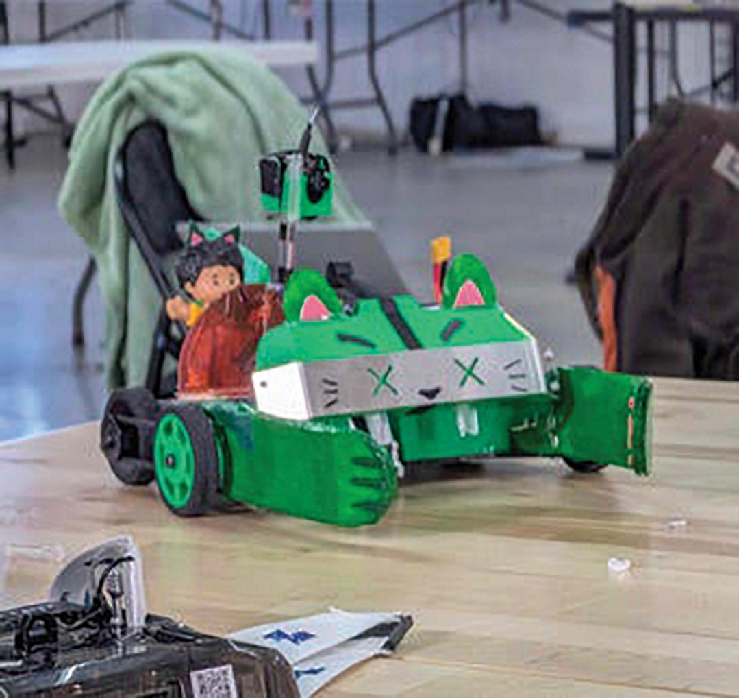
“I decided that I wanted to add cat ears just because I thought it’d be cute,” said information technology major Irene Ashma Hossain. Those playful touches evolved into practical enhancements: static paws for herding, a pan-tilt tail for maneuverability, and modified wheels for stability.
“It ended up being really effective,” said De Costa.
The 24-hour event tested endurance and ingenuity. Against a backdrop of camera crews and livestreams, George Mason’s team stood out for its creativity and adaptability. Even after a late-night power outage forced participants to improvise, the team completed two rescue runs, performing “emergency surgery” with duct tape between rounds. Their determination paid off: second place, ahead of the prominent YouTubers’ team. By blending creativity, technical skill, and resilience, the team demonstrated George Mason’s interdisciplinary strength, innovative mindset, and ambition.
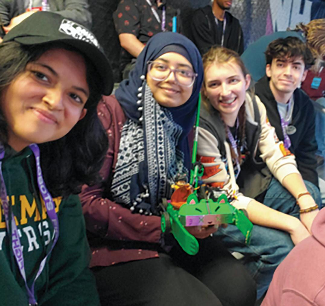
From left to right: Alexia Marie De Costa, Irene Hossain, Meah Chambers, and Luis Anchundia.
George Mason is Launching a Space Forward Frontiers Seminar with Northrop Grumman
GEORGE
MASON UNIVERSITY’S COLLEGE OF SCIENCE is launching the Space Forward Frontiers Seminar Series in spring 2026, in partnership with Northrop Grumman and George Mason’s College of Engineering and Computing.
The one-credit, in-person seminar (PHYS 391/590, cross-listed as ME 500) is open to undergraduate and graduate students of all majors interested in the space industry.
Limited to 50 students, the Thursday afternoon seminar features weekly lectures from George Mason faculty and industry professionals, offering practical
and academic perspectives on today’s space sector. Topics include the space industry’s foundations, enabling technologies, policy considerations, and future directions, with the inaugural offering focusing on crowding and events in the space environment.
With no prerequisites or textbooks, the course is highly accessible and connects students to such emerging opportunities as NASA’s Landolt Mission, led by George Mason faculty. The seminar also supports the university’s Grand Challenge Initiative (GCI), advancing both 21st-century education and pioneering space exploration through industry collaboration.
College of Engineering and Computing Hosts Mechanical Engineering Education Conference
GEORGE MASON’S COLLEGE OF ENGINEERING AND COMPUTING (CEC) hosted the American Society of Mechanical Engineering’s Mechanical Engineering Education Conference (MEEd) from March 29 - 31 on its Mason Square Campus.
Since its inception in 1989, MEEd is the only conference designed for mechanical engineering (ME) and engineering technology educators and leaders from academia, industry, and government. Participants consider current and future challenges and opportunities impacting ME education.
Leigh McCue, chair of CEC’s ME department, served on the organizing committee and said, “Leveraging George Mason’s strong Northern Virginia presence, we are able to offer unique panels drawing from the industry base in our region; for example, I was particularly excited for a defense industry future workforce panel which included John Main of DARPA, Elissa Trueman of the Naval Surface Warfare Center, Carderock Division, and Mat Winter, Vice Admiral, U.S. Navy (ret) and now with Winter Strategic Solutions.”
Other George Mason faculty and staff on the program were Colleen Berg, associate chair for undergraduate programs in Mechanical Engineering; Bonnie Crews, CEC senior director of advancement and alumni relations; Maria Emelianenko, chair of mathematical sciences in the College of Science; Lewis Forrest, assistant vice president for University Life; Nathan Kathir, professor and director of senior projects in Mechanical Engineering; Ariela Sofer, divisional dean for the Volgenau School of Engineering and professor of Systems Engineering and Operations Research; and Janis Terpenny, professor in Systems Engineering and Operations Research and Mechanical Engineering and ASME Fellow. ME student Joseph Daly was a panelist.
Andre Marshall, the university’s vice president for Research, Innovation, and Economic Impact, also gave remarks. He said, “George Mason is honored to host MEEd as educators and leaders explore interdisciplinary, applied, and inclusive pathways in mechanical engineering education—ensuring our programs reflect the realities of today’s workforce and tomorrow’s challenges.”
Topics this year include mathematical foundations, AI, advanced manufacturing, fundraising, and industry engagement. George Mason used the hosting opportunity to showcase novel laboratories such as Liling Huang’s Energy Exploration Center;
Xuesu Xiao’s RobotiXX Laboratory; and Brett Josephson’s (Costello College of Business) AFCENT Futures Lab, which particularly highlights the multidisciplinary, collaborative nature of George Mason’s research and education ecosystem.
Dean Ken Ball opened the event by introducing ASME President Lester Su, who then introduced keynote speaker and President of the National Academy of Engineering (NAE), Tsu-Jae King Liu, who spoke about the importance of communicating the value and benefits of an engineering education to the general public. She cited the NAE’s report, “Changing the Conversation,” and its guidance on talking points for engineering educators trying to reach young people.
The session “Training A Workforce for 21st Century Manufacturing” explored how engineering programs can adapt curricula, integrate hands-on experiences, and strengthen problem-solving skills to align with evolving industry standards and workforce needs. Among the panelists was Shannon O’Donnell, Global Future Workforce Engagement Lead for Siemens Digital Industries Software. “There are many benefits to industry and academia collaborating in and beyond this event. It helps new graduates, in particular, through a stronger lifelong learning ecosystem, supporting learners’ digital mindset and skillset.” said O’Donnell.
At the conclusion of the conference, which included two days in sessions and a pre-conference event day, some attendees boarded a bus and went into the District for a Washington Capitals hockey game. McCue said, “With the cherry blossoms in bloom, this is a wonderful time to show off George Mason and our region, and I’m so honored we were able to host MEEd.”
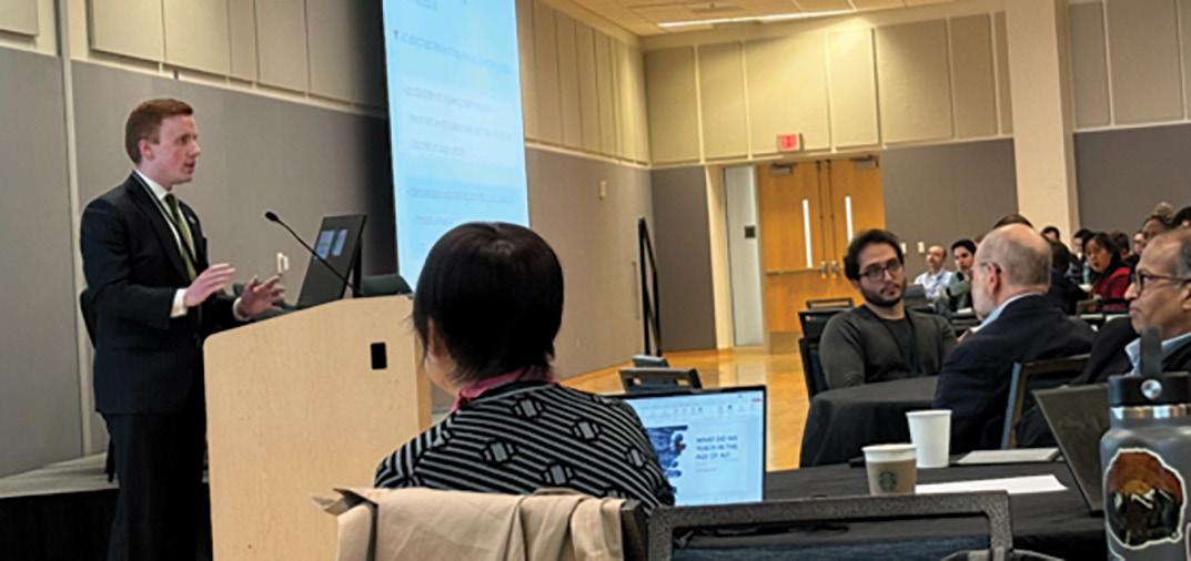
Mechanical engineering student Joseph Daly spoke on a panel titled, “Shaping AI in ME Education.”
George Mason Researcher Receives NSF CAREER Award to Study How Autonomous Systems Communicate
FOR DAIGO SHISHIKA , robots are not just machines that move… they can also be experts at communication of various types. With a new CAREER award from the National Science Foundation (NSF), he is advancing a line of research that asks a deceptively simple question: what if robots could “talk” to each other—and to humans—without ever sending a signal?
Shishika, an assistant professor in George Mason University’s Department of Mechanical Engineering, will lead a five-year, $549,000 award focused on how autonomous systems can signal intent through motion alone. The idea draws from everyday human experience, Shishika said, giving the example of how drivers read each other’s behavior on the road not just through turn signals, but also through speed, positioning, and subtle cues. Pedestrians do the same when navigating crowded sidewalks. The research aims to give robots that same intuitive layer of interaction.
“There’s a lot of information that comes from pure observation of movement. So how can robots take that into account? If I move in this way, how would that be perceived?” he said. Citing the ubiquitous Starship food-delivery robots around campus, he added, “When you walk near one, you kind of have to guess what it’s trying to do based on what you see it doing.”
The project builds on years of research at the intersection of robotics, control systems, and game theory. Shishika’s path to this point has been shaped by a longstanding fascination with motion. As an undergraduate at the University of Tokyo, he studied aerospace engineering, initially drawn to flight systems and small aerial vehicles. That interest led to research on bumblebee flight dynamics. Over time, his focus expanded from how individual systems move to how multiple systems interact. His graduate work at the University of Maryland involved drone swarms inspired by insect behavior.
As a postdoctoral researcher at the University of Pennsylvania, he worked on multi-agent systems in defense-related contexts, where coordination played a critical role. That experience laid the foundation for his current work, examining both cooperative and adversarial interactions among autonomous agents.
A central concept in the project is what Shishika described as the spectrum between transparency and deception. In some cases, robots need to clearly signal their intent to build trust and operate safely alongside humans. In others, such as security or defense applications, limiting the information revealed through motion can be just as important.
“If a system moves in a certain way, it may unintentionally reveal what it’s trying to do,” he said. “So the question becomes, how much information are you giving away through your actions, and can you control that?”
The implications span a range of applications. Delivery robots, for example, could plan routes that make their destinations less predictable, improving security for sensitive shipments. In public spaces, robots that better communicate intent through motion could navigate more smoothly around people, reducing confusion and improving safety. On a larger scale, the work could inform how infrastructure and policies are designed.
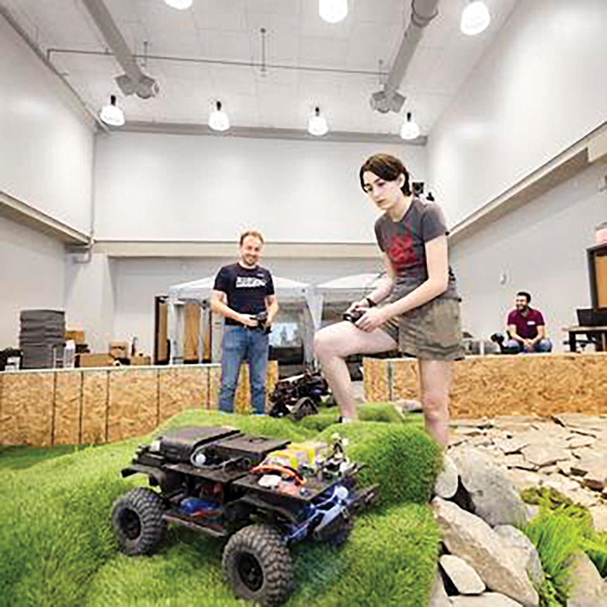
The project will also integrate theoretical and experimental work through Shishika’s Robo Game Arena, a platform combining mathematical modeling with physical robot experiments. By testing how real systems behave and how humans interpret those behaviors, he aims to bridge the gap between theory and practice.
The NSF CAREER award is reserved for the nation’s most talented up-and-coming researchers. From the NSF website: “The Faculty Early Career Development Program offers NSF’s most prestigious award in support of early-career faculty who have the potential to serve as academic role models in research and education and to lead advances in the mission of their department or organization.”
For Shishika, the award represents both recognition and opportunity. It is his first project developed as a full lab effort, bringing together students working across theory, machine learning, and hands-on robotics.
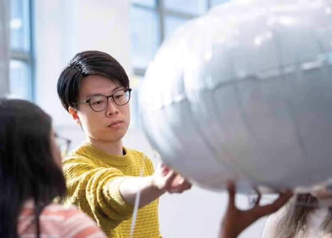
Professor Daigo Shishika working with students on blimps in the MARC aviary. Photo by Evan Cantwell/George Mason University
A Topology Tutorial in Lighter-but-Stronger
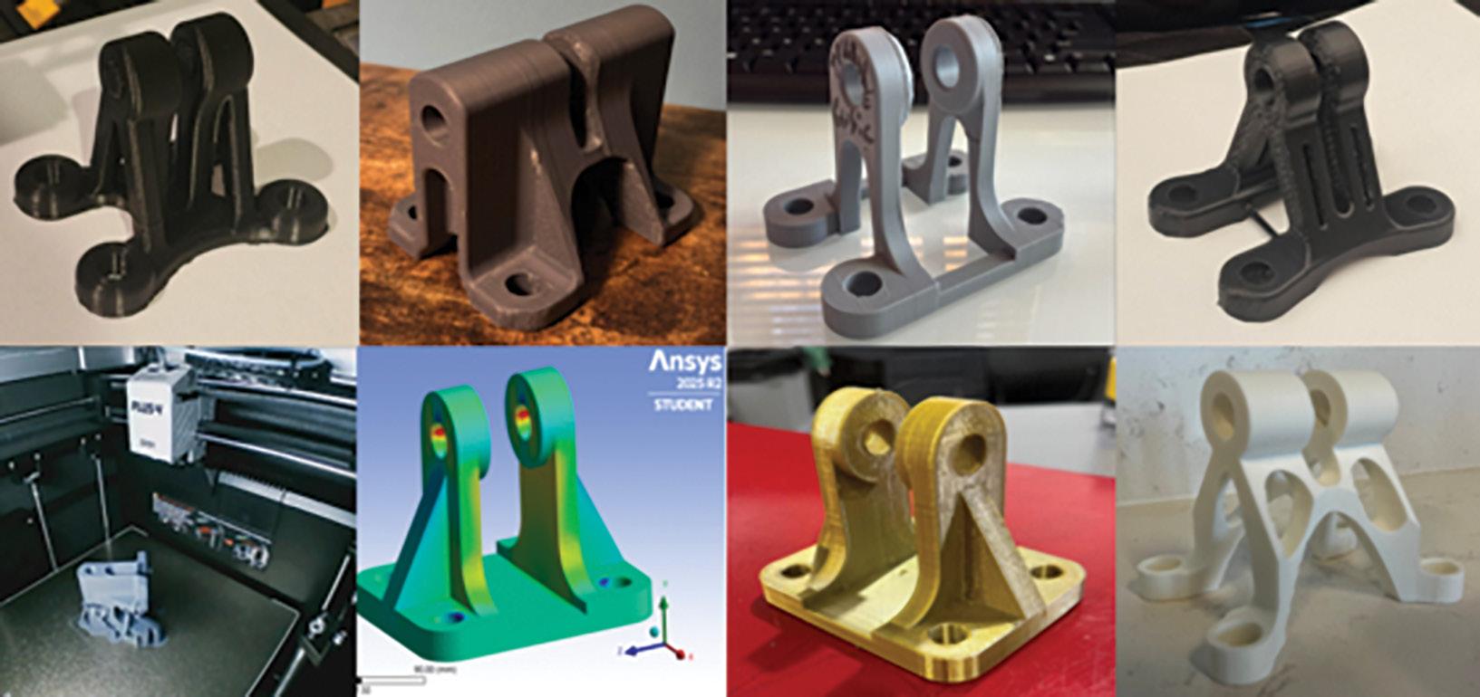
Mehdi Amiri is using hands-on learning, software simulation, and 3D printing to teach students the concept of topology optimization, a design method that reshapes a structure to maximize performance while minimizing material. This helps create lightweight and efficient parts, without sacrificing strength and, consequently, safety.
Amiri, an assistant professor in the Department of Mechanical Engineering, has students in his finite element analysis (FEA) class consider a complex system like an airplane. “It has a lot of components which go under loads, they vibrate, and then eventually the parts will fail,” he said.
He gives students an original bracket component and using technology donated by software company Ansys, “They do computer simulations and then predict when it’s going to fail, where it’s going to fail, and why it is failing in the way that it will fail.” They then 3D print the part and attempt to optimize it so that it will fail after withstanding higher loads or will fail in a way that’s different or not expected.
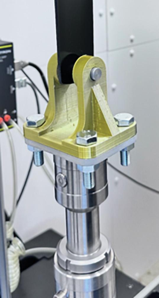
At the end of the semester, students gather to test their new design in a SciTech campus lab in a day of high drama for them. “They don’t see each other’s design until test day and then they get to ask each other a lot of questions about how they came up with different designs,” Amiri said. “They really like testing to see where the part breaks in one location versus another. They compare it with what they did in the simulation, and they are very happy when their predictions were accurate.”
Amiri gives out a first, second, and third place prize to students, based on their part’s strength to weight ratio. Amiri said the relationship with Ansys is beneficial for the students. He received $10,000 from the company last year to develop curriculum for a prior class. The company then proposed free use of their software for the current FEA class. Amiri checks in with an Ansys representative regularly to update them on student progress and give feedback.
The students’ 3D-printed parts.
A sample bracket the students used as a model.
Mechanical Engineering Advisory Board
The Mechanical Engineering Advisory Board (MEAB) plays a vital role in helping George Mason University develop the program by providing direct input on the skills students need to be successful in their careers.
The Mechanical Engineering Student Advisory Board (MESAB) facilitates communication between department leadership and the student body. While any student is welcome to offer opinions and feedback to the department, MESAB meets with department leadership regularly to do so. The department asks members to provide feedback on a wide range of issues and proposals under consideration.
Members
◆ Veronica Sinai Padrino Aguero
◆ Anthony Lizarazu Ampuero
◆ Vanessa M. Barth
◆ Sampada Basnyat
◆ Adam Chiguer
Graduate Student Awards
◆ Shaheen Mahmood, Provost’s Office Summer Graduate Research Assistantship
◆ Lexi Chivers
◆ Morgan R. Coltrain
◆ Meryem El Kasbi
◆ Prabhath K. Gera
◆ Ethan Mingkwan Hebert
◆ Alexia A. Joachim
◆ Kritagya Khadka
◆ Nicholas Thomas Kinnear
◆ Christie Lluis
◆ Kunal Sharma
◆ Aarij Jamil Syed
◆ Owais Yousuf
◆ Shaheen Mahmood, Graduate Student Travel Fund
◆ Sabrina Islam, Graduate Student Travel Fund
Undergraduate Student Awards
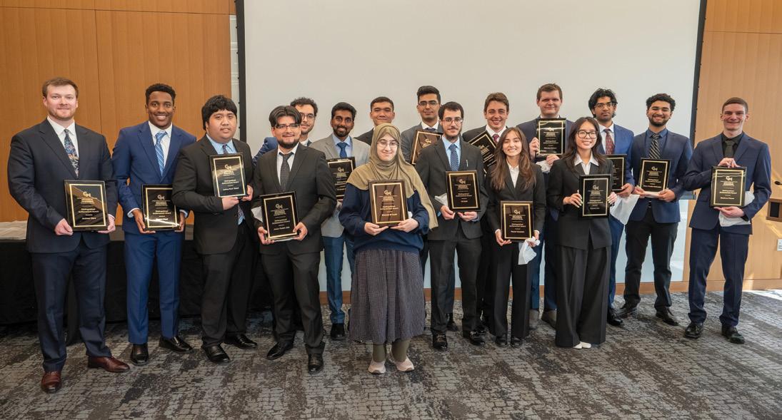
Distinguished Achievement Award
The recipients of the Distinguished Achievement Award have consistently shown exceptional academic ability in the classroom.
While these students have routinely earned university accolades such as placement on the Dean’s List, we want to recognize them in front of their peers on Capstone Day and thank them for rising to the high expectations we place on our students every day.
◆ Rasean Boyd
◆ Javier Carpio Jota
◆ Andres Cruz Guzman
◆ Meryem El Kasbi
◆ Prabhath Gera
◆ Daniel Horvath
◆ Abbas Hussain
◆ Ali Kabli
◆ Nicholas Kinnear
◆ Shreyes Kumar
◆ Connie Lam
◆ David Lancaster
◆ Matthew Pisone
◆ Brian Portillo Melendez
◆ Joshua Kent Siasat
◆ Noemi Umanzor
◆ Jackson Ware
Distinguished Achievement Award—Aerospace
◆ Ethan Hebert
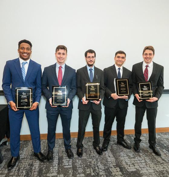
Distinguished Service Award
The Distinguished Service Award was established in 2018 to recognize students who have led a significant student initiative during their time at Mason.
These initiatives carry significant benefit to the Mason student body and often come at the expense of the recipient’s GPA, bank account, and certainly sleep...
◆ Lexi Chivers
◆ Joseph Daly
Chair’s Award
◆ Prabhath Gera
◆ Noemi Umanzor
The recipients of the Chair’s Award represent the department’s guiding principles.
◆ Philip Acatrinei
◆ Rasean Boyd
◆ Danny Castro
◆ Daniel Horvath
◆ Ali Kabli
◆ David Lancaster
OSCAR Student Excellence Award
◆ David Lancaster
Faculty Awards
◆ Ali Beheshti was recognized as a Teacher of Distinction, George Mason University.
◆ Mary “Missy” Cummings received the American Institute of Aeronautics and Astronautics (AIAA) Intelligent Systems Award.
◆ Pei Dong was named a Fellow of the American Society of Mechanical Engineers (ASME).
◆ Pei Dong was awarded the College of Engineering and Computing Faculty Excellence Award – Excellence in Research
2025 Faculty Grants
FACULTY
Mehdi Amiri (PI)
Mehdi Amiri (PI)
Shay Bagheri (PI), Ali Beheshti (Co-PI), Caroline Hoemann (Co-PI)
Shay Bagheri (PI)
Ali Beheshti (PI)
Ali Beheshti (PI)
Mary “Missy” Cummings (PI)
Brett William Josephson (PI), Cameron Nowzari (Co-PI), Ali Khalid Raz (Co-PI), Daigo Shishika (Co-PI), Shima Mohebbi (Co-PI)
◆ Pei Dong was appointed as one of the General Conference Chairs of the 19th International Conference on Energy Sustainability (ASME-ES).
◆ Nathan M. Kathir was appointed as commissioner effective July 2026 for the Engineering Technology Accreditation Commission of ABET.
◆ Daigo Shishika was awarded the National Science Foundation CAREER Award.
◆ Janis Terpenny was named a Fellow of the American Society for Engineering Education (ASEE).
Coupled Corrosion and Fatigue Lifing Tool for Aero-Propulsion Components
Advanced Fretting Fatigue Life Prediction Method for Naval Aerospace Applications
MRI: Track #1 Acquisition of a 3D X-Ray Computer Tomography Scanner for Multidisciplinary Research and Education
Bio-Inspired Cellular Metamaterials: Design for Additive Manufacturing
Finite Element Based Crack Initiation and Propagation Study for Gear Steel Alloy
Tribo-Corrosion Study of Nickel-based Superalloys Subjected to Laser Peening
Autonomy Standards and Ideals with Military Operational Values (ASIMOV)
$105,885
LLC
Advanced
Projects Agency $101,791
Quentin Sanders (PI) Fused Filament Fabrication of Customized Continuous Fiber Physical Activity Enabling Prostheses for Children with Lower Extremity Amputation
Quentin Sanders (PI)
Enhancing Daily Activities of Living in Stroke Survivors Through Semi-Autonomous Hand Exoskeletons with Multi-Modal Sensing
Ningshi Yao (PI), Qi Wei (Co-PI), Quentin Sanders (Co-PI) Study Coordinated Human Eye Movement and Strabismus using a Novel Artificial Muscle-Driven Robotic Eyes
Department of Mechanical Engineering faculty are bolded. Only Mason PIs and Co-PIs are listed. Grants are listed alphabetically by the surnames of the projects’ main PIs.
Welcome to Capstone Day
Nathan M. Kathir Professor and Director of Senior Projects
Website
mechanical.gmu.edu
Email nkathir@gmu.edu
Phone
703-993-5283
IT IS MY GREAT PRIVILEGE TO WELCOME EVERYONE to the 10th Annual Mechanical Engineering Capstone Day in our young Department of Mechanical Engineering’s 11-year history! This is also a very special occasion for me as this will be my final Capstone Day as the director of senior projects before I retire from George Mason University. I will cherish this moment for the rest of my restful life!
Our 94 seniors have undertaken a variety of projects provided by our sponsors, overcome various challenges, and are ready to showcase their creativity, decision-making abilities, and problem-solving skills. Today’s event is made possible by friends, sponsors, supporters, faculty, advisors, and staff.
As the director of senior projects, I have witnessed how our students worked together over two semesters to complete their projects despite numerous challenges and frustrations occurring throughout. They gained experience in teamwork, leadership skills, public speaking, and project management to accomplish various tasks using the skills learned in previous courses while also acquiring new knowledge needed to complete their project. ABET accreditation criteria require that the curriculum includes a culminating major engineering design experience, and our capstone program exceeds that requirement with the additional hands-on experience of having the teams prototype, test, and validate their design.
Starting a project with an approximate and illdefined problem, the students go through project scoping, budgeting, planning, design, project management, and prototyping their design in the machine shop. At the end, they have gained “realworld” type engineering experience and are ready to enter engineering practice or graduate studies. Students also satisfy the university’s requirements for Writing Intensive and Apex by completing the Mechanical Design, i.e., the capstone course.
Every year, I try to add something new to the program to provide additional excitement and experience. This year, our program partnered with Nexus234 Innovation District, which provided funding support and organized industry partners
to offer technical advice to three student teams. Continuing from last year, one team partnered with the engineering college of KARE University in Tamil Nadu, India. This opportunity has given our students experience working with a globalized workforce.
Our students’ success with these projects is in large part due to mentoring by sponsors, faculty advisors, my co-instructors Dr. Charles White and Mr. Colton Talley, and the encouragement provided to students by their family and friends. Acknowledgement is also due to the assistance provided by the department’s critical support staff: Machine Shop Manager Johnnie Hall, IV, and LSEB Instructional Technician Josh Dunn, Administrative Specialist Timothy Diggins, and Financial and Budget Specialist Krista Tran. Finally, I am thankful to the College of Engineering and Computing and Department of Mechanical Engineering leadership for letting me do what I enjoy the most – sharing my engineering and program management experience to nourish the bright minds of future engineers and leaders.
As enrollment in the program continues to grow, the Department of Mechanical Engineering is always looking for new capstone project sponsors to enrich students’ educational experience. Please contact us if you have a challenging capstone idea that our young engineers can help solve. Even if you have an incomplete idea, our students can help you formulate a great challenge and then help you find solutions! The sponsors get a well-engineered and tested product or solution at a low risk. They also have a chance to observe promising engineering talents before they graduate. To the graduating mechanical engineering class of 2026, congratulations – we are very proud of you on this momentous occasion. Welcome back any time and keep in touch as you begin your life-long learning!
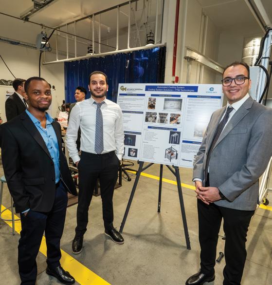
Team Cooling System Solutions
Team Lead
Makary Meseha
Team Members
Armold Poutong
Maitree Rout
George Zaki
Sponsor
TTM Technologies, Inc.
Faculty Advisor
Saanyol Igbax
Acknowledgements
Johnnie Hall, IV
Brian Keefer
Jhonatan Lavayen
Sean Muzzio
Krista Tran
Design of a Cooling System
Problem Definition and Original Deliverables
TTM Technologies, Inc. manufactures printed circuit boards (PCBs) used in the defense industry. As part of the manufacturing process, film lamination requires a copper panel to be preheated, the film to be applied using hot rollers, and then a cooling process to return the panels to ambient temperature. Accelerating the cooling process not only decreases cycle time but also helps prevent defects caused by the film being pulled into holes in the material due to differing cooling rates between the material and the surrounding air. Team Cooling System Solutions was tasked with designing a system to improve the cooling rate of the panel after the film is applied.
Design Requirements
The current cooling system consists of a commercial standing fan. The sponsor asked Cooling System Solutions to design a cooling system capable of reducing the panel temperature from 80°C to ambient temperature within three minutes. The system should include a smart on/off function that detects when a product is approaching the accumulator and automatically activates the cooling process, then shuts off once sufficient cooling has been achieved, as determined by a timer, distance, or temperature sensor. The cooling system must integrate seamlessly with the panel accumulator and be easily movable to allow facility technicians access during preventive and corrective maintenance of the conveyor or lamination machine. Additionally, the system should utilize easily replaceable and widely available commercial off-the-shelf (COTS) components. Finally, the design should enhance operator comfort by directing airflow in a manner that prevents air from being blown directly onto the operator during the cooling cycle.
Final Design Description
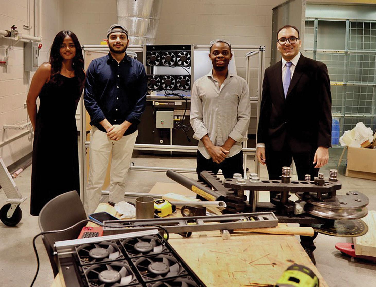
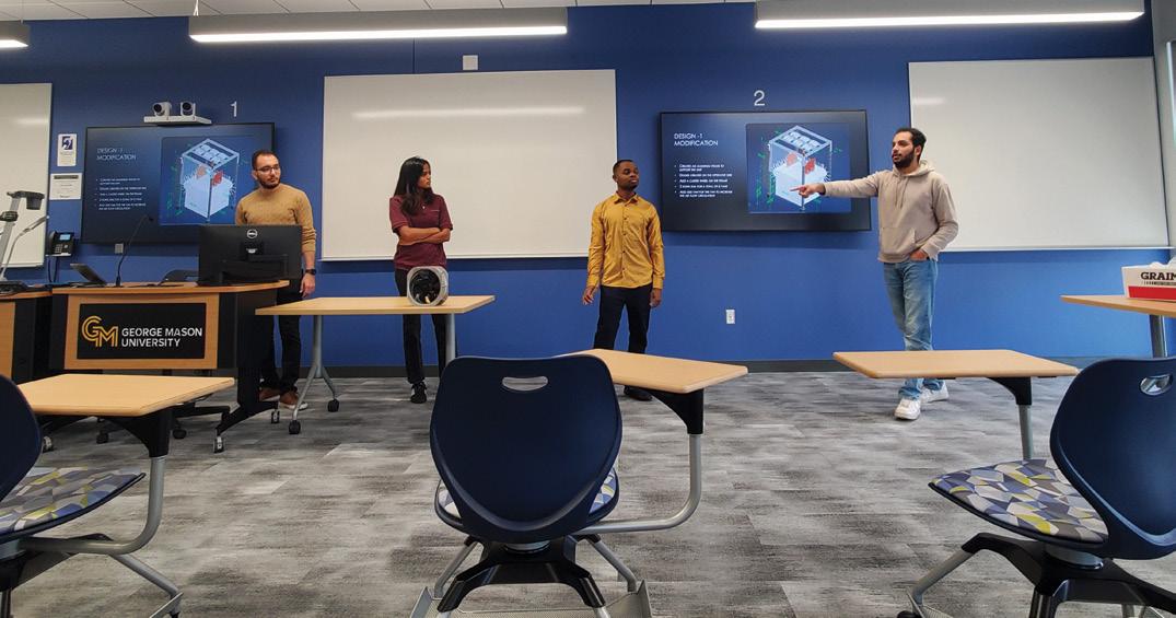
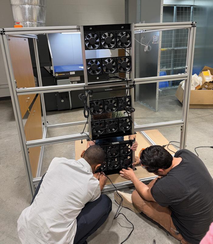
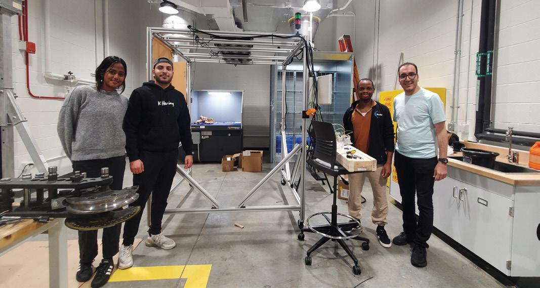
Through a series of preliminary designs and feedback from the sponsor, the team opted for a fan enclosure system. The unit is primarily constructed from a T-slotted aluminum frame, which supports a series of vertically oriented fans that blow air downward onto the panel, along with an additional fan that blows air horizontally to maximize air circulation. The frame is mounted on four rotating caster wheels to facilitate mobility. On the operator side, two plexiglass doors are installed to reduce airflow toward the operator, particularly from the horizontal fan. The fans are controlled by a distance sensor located at the exit of the lamination machine and a PLC system that manages fan operation and a beacon light. The beacon light indicates the operating status of
the fans: green when all fans are running, yellow in the event of a jam, and red when the system is stopped. Emergency stop buttons are located on each side of the unit, allowing operators to shut down the system if necessary. Additionally, a temperature sensor installed at the back of the unit measures the temperature of the most recently processed panel and displays the reading on a screen.
Validation and Testing
The team conducted a series of validation tests to assess and verify the performance of the proposed design. The initial evaluation focused on the structural stability of the frame. A detailed analysis was performed using Autodesk Inventor to simulate the loads generated by the installed fans. The results indicated that the induced stresses including bending, compressive, and torsional stresses were negligible and well within acceptable limits, confirming the structural integrity of the frame under operating conditions.
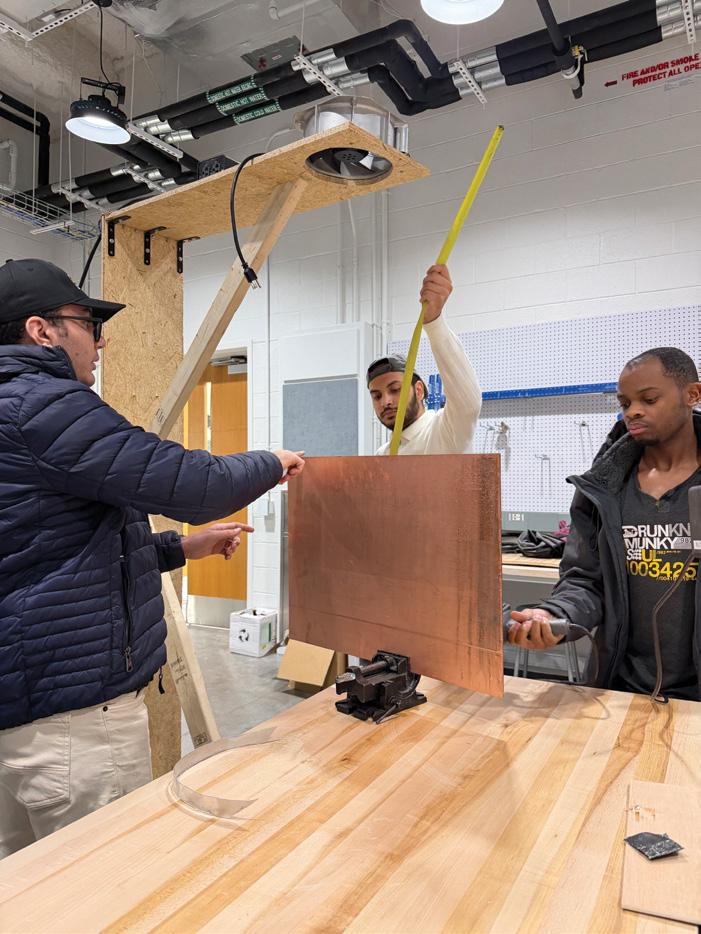
A second phase of testing was conducted to validate the calculated airflow requirements (CFM). In this test, a
panel was heated to the specified operating temperature and subsequently cooled using a preselected fan configuration. The cooling performance was measured and compared against the design expectations. Based on the experimental results, adjustments were made to the fan selection, leading to the replacement of individual fans with tray-mounted fans rated at 835 CFM each. This modification improved airflow consistency and overall cooling efficiency, ensuring the system meets the required cooling performance criteria.
Conclusions and Future Work
The final design for the cooling system successfully meets all the requirements. It ensures a reliable, efficient, and automated
system for the rapid cooling of the PCB panels after lamination and reduces the temperature of the panels from 80°C to ambient temperature within the required time frame while ensuring the structural integrity of the system. The use of sensors, a PLC system, and a proper airflow makes the system efficient and easy to use in an industrial setting. The proposed system also provides a number of benefits. Firstly, it reduces production cycle time, thereby improving manufacturing efficiency. Secondly, it reduces production defects resulting from uneven cooling, thus improving product quality, and minimizing wastage of materials. Thirdly, it is costeffective and easy to maintain and replace parts due to the use of commercial off-theshelf technology. Lastly, smart automation
technology ensures system reliability and safety, owing to sensor-activated operation and a beacon light to show system status. Overall, the proposed system is a practical solution to a real-world problem, and it is likely to be easily implemented in an industrial setting.
Team BOAT
Team Lead
Matthew Pisone
Team Members
Mark Bartolome
Jose F. BerriosRodrigue
Joshua Dehoff
Jon Tran
Sponsor
Vision Point Systems, Inc. (VPS)
Faculty Advisors
Shaghayegh Bagheri
Kunal Gide
Acknowledgements
Dan Coyle
Josh Dunn
Matt Frichtl
Johnnie Hall, IV
Nathan M. Kathir
Philip Payne
Tobie Payot
Krista Tran
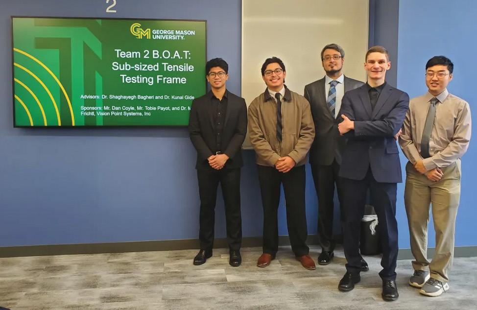
Sub-Sized Tensile Testing Frame
Project Definition and Original Deliverables
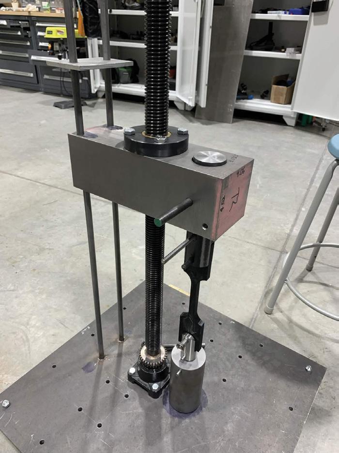
Vision Point Systems, Inc. (VPS) performs material testing on metal specimens using tensile testers. These testers can be large and take up a lot of space. As the capabilities of testers can vary, you may need two machines depending on the tests you need to perform. Purchasing two testers is costly, and making space for both is inconvenient. Team BOAT’s solution is to design a tensile tester with two different testing systems in one machine that has a wider range of capabilities and is small enough to fit on top of a table. One system uses a lead screw and worm gear for tension testing, and the other uses a ball screw and chain for fatigue testing.
Design Requirements
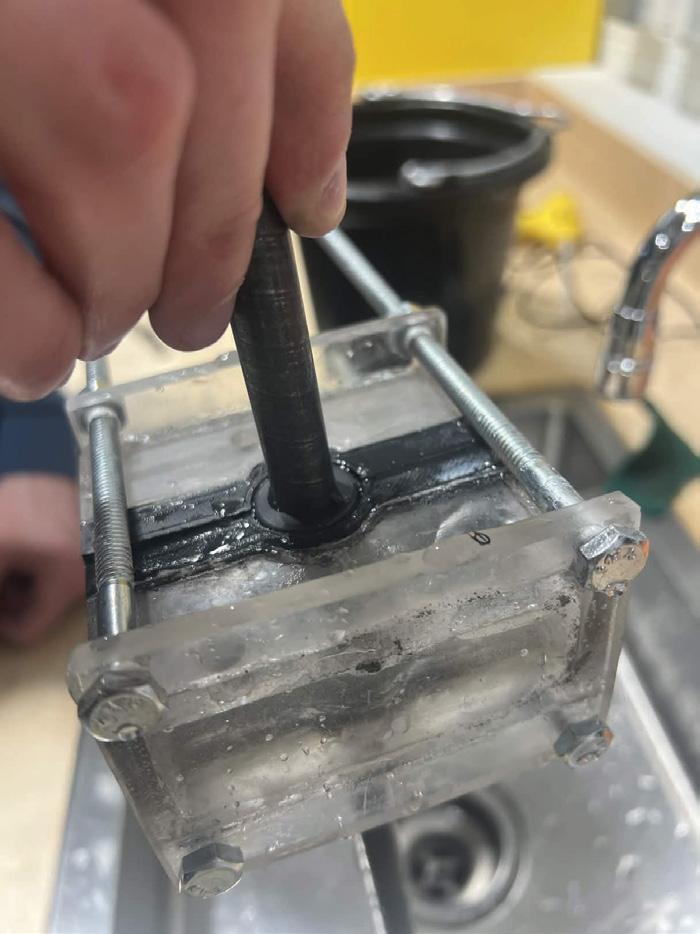
The testing frame needs to safely perform tensile and fatigue tests with loads up to 10 kN while accurately measuring and controlling load and displacement. The design needs to be capable of performing both fatigue testing and tensile testing while still being small enough to fit on a tabletop. The frame needs to perform a stress corrosion cracking test, and VPS requested an inert testing enclosure for containing seawater. The primary requirement for the enclosure is that it cannot use an applied lacquer to seal it.
Final Design
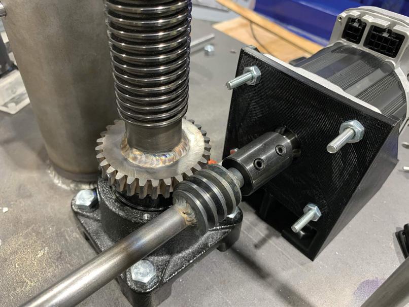
The design is split into two systems, one for tensile and one for fatigue testing. The tensile system uses a lead screw driven by a worm gear system to control load and displacement. The fatigue system applies cyclic loading by using a ball screw driven by a chain. Two servo-motors are used to drive each system because of the large torque output and high precision, ensuring that the required load can be both produced and controlled.
The final design uses a single-lead screw driven by one servo-motor through a worm gear with 30:1 ratio, allowing the motor to generate the required load with a lower torque input. The leadscrew moves the steel crosshead, which holds the upper grip and load cell to apply and measure the tensile force on the specimen.
A fatigue system was designed as a separate unit mounted above the upper grip so cyclic loading can be applied without changing the tensile system. This system uses a ball screw driven by a servo-motor connected through a chain and sprocket to increase torque and produce repeated loading. The fatigue unit can be locked in place when not in use, so the frame stays rigid during tensile tests.
Fabrication and Testing
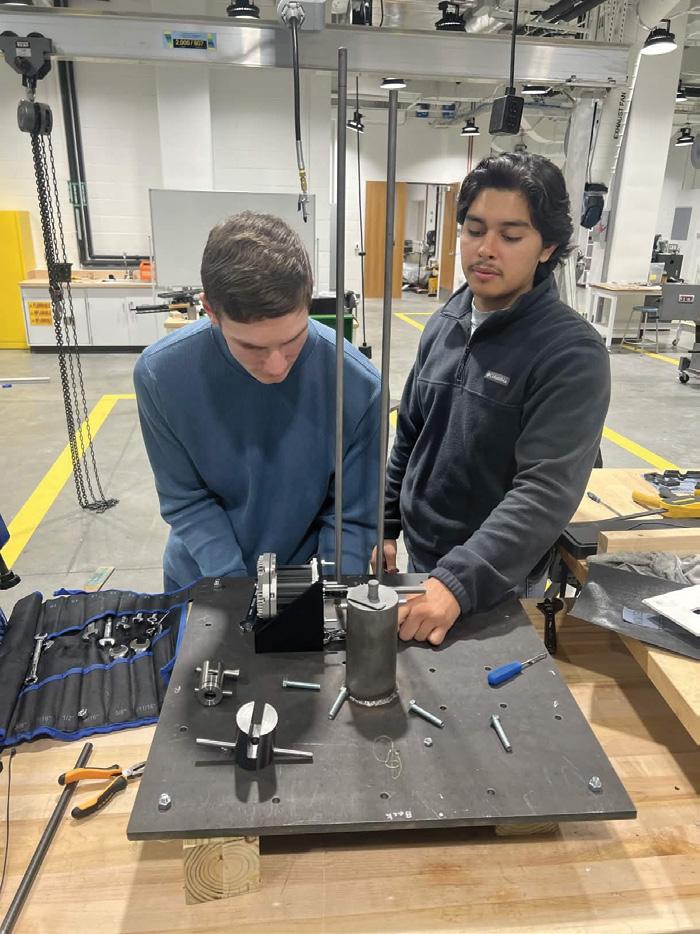
The fabrication process involved machining the main structural components to ensure proper fit and alignment of the system. The baseplate was machined with the required holes for mounting the leadscrew, guide rods, and frame supports. The crosshead was machined to fit the leadscrew nut, guide rods, fatigue mount, and locking pins. The leadscrew was bored to provide space for the worm gear connection, and the bottom grip was machined to properly hold the test specimens. Since only one grip was provided, a second grip was machined to match the original with a spare part.
Aluminum plates were cut and shaped to build around the fatigue system, and acrylic panels were cut to create the environmental chamber around the test area. A motor mount was also 3D printed to hold the servomotor. During fabrication, adjustments were made as needed to improve the design.
The frame design was verified using finite element analysis (FEA) to confirm that it could safely handle the required loads and remain stiff during operations. The crosshead, screw assembly, baseplate, lower grip mount, and fatigue system housing were analyzed under a 10 kN
load. In all cases, the stresses were below the allowable limits and the displacement was much less than 1 mm, showing that the frame will not fail and that the movement will not affect test accuracy. The full frame analysis was done in sections due to software limits, and the highest stresses occurred near the test specimen as expected. A mesh sensitivity analysis was also performed on the crosshead and baseplate to verify the result, confirming that the frame is strong enough and suitable for tensile and fatigue testing.
System Benefits
Modern testing environments do not have the luxury of space; being able to implement multiple test beds within one machine can be considered a quality-of-life improvement for the research field. This design allows tensile and fatigue testing to be done on one machine, saving space and reducing the need for multiple test setups. This simple structure makes the system easier to build, use, and maintain, while still providing accurate load and displacement measurements.
The design is useful for research and lab environments where space, cost, and flexibility are important, and it can also be used with an environmental chamber for testing in a corrosive environment.
Conclusion
Team BOAT designed, built, and tested a tensile and fatigue testing frame that can safely apply the required loads while keeping stress and displacement within acceptable limits. The final design uses a single screw system for tensile testing and a separate system for fatigue loading, allowing multiple tests to be done on one compact machine. Fabrication and FEA testing confirmed that the frame is strong, stable, and accurate, making it suitable for laboratory and research use.
Team Precision Solutions
Team Lead
Jack Lecker
Team Members
Wesam Mashal
Andrew Ngo
Remi Pepelko
Sponsor Vision Point Systems, Inc. (VPS)
Faculty Advisor
Shirin Movaghgharnezhad
Acknowledgments
Stephen August
Nathan M. Kathir
Wayne McGaulley
Consistent Force Burnishing Tool and Soft Close Micrometer
Project Definition and Original Deliverables
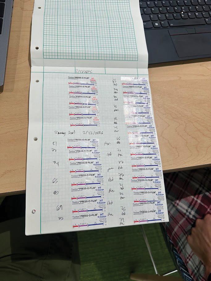
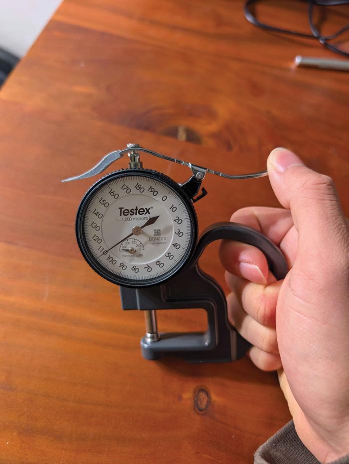
When preparing a surface for painting, workers use Testex tape to measure its surface roughness. Workers must apply the tape with a specific amount of force and gently use a micrometer to measure its resulting thickness. This process is critical in naval work, where poor coating quality can ruin a vessel. Vision Point Systems, Inc. (VPS) needed to improve the consistency and reliability of both parts of this process, so they tasked Team Precision Solutions with developing a pair of tools to solve these challenges. These tools needed to be reliable, relatively affordable, and produce consistent measurements that match the actual surface roughness.
Tool Requirements
The primary objective of the burnishing tool is to ensure that all users are applying Testex tape properly. Users often do not apply the tape evenly or with sufficient force, and both outcomes lead to inaccurate readings. The updated design must ensure that sufficient force is applied while remaining a simple, low-cost solution that is durable for abusive field conditions.
The primary objective of the micrometer is to avoid damage to Testex tape samples during measurement. VPS has observed users allowing the hammer of existing micrometers to slam closed on tape samples, which severely affects the accuracy of measurement.
Design Concepts
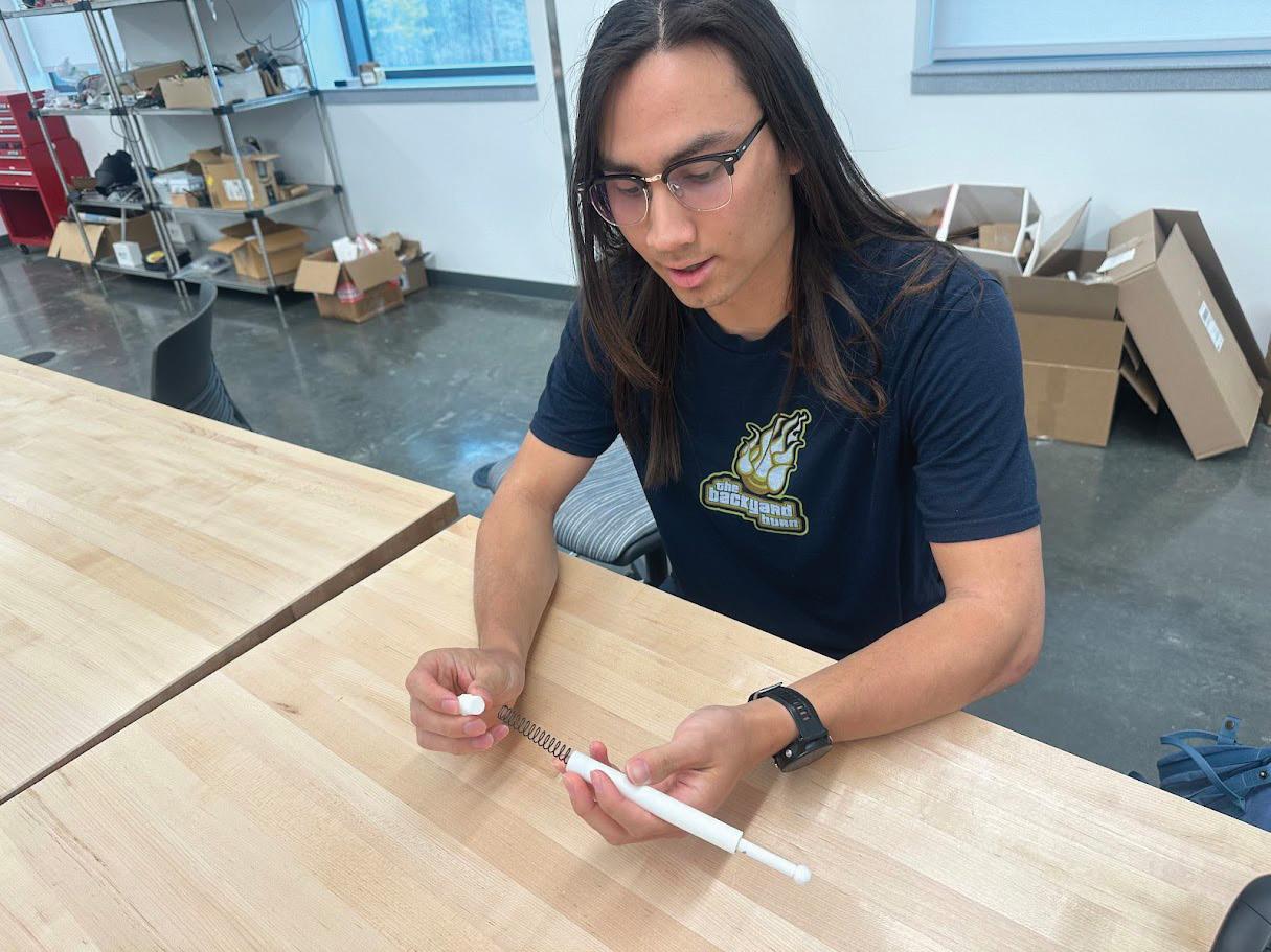
Two concepts for the burnishing tool were initially considered: a pen-style tool and a stamp-style tool. The pen-style tool has an elongated housing with an internal spring and a ballpoint tip to burnish Testex tape. The force of imprinting varied with the displacement of the tool. The stamp-style tool was short and stubby and was designed to imprint with a quick compression of the palm.
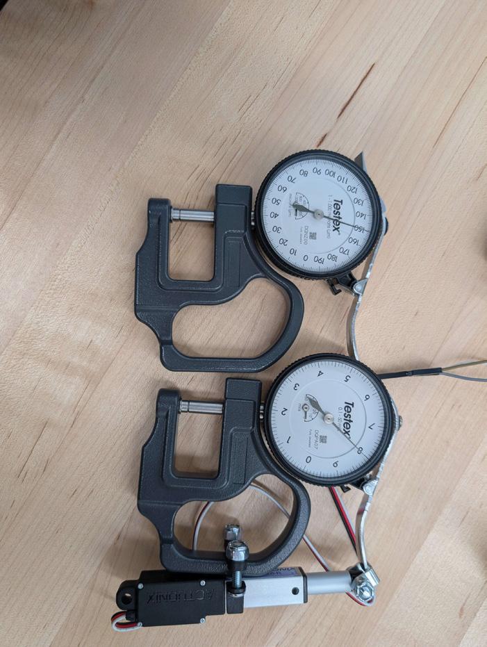
As for the soft-close micrometer, a linear actuator and a gas spring were considered. By using an electronically controlled actuator to control the throw of the lever, user error can be removed from the measuring process. This mechanism will be covered in order to prevent damage or tampering. A gas spring is a common mechanism used in car trunks and storm doors to allow for a softclose function. This design could be a scaled down version to suit our needs.
Final Design and Validation
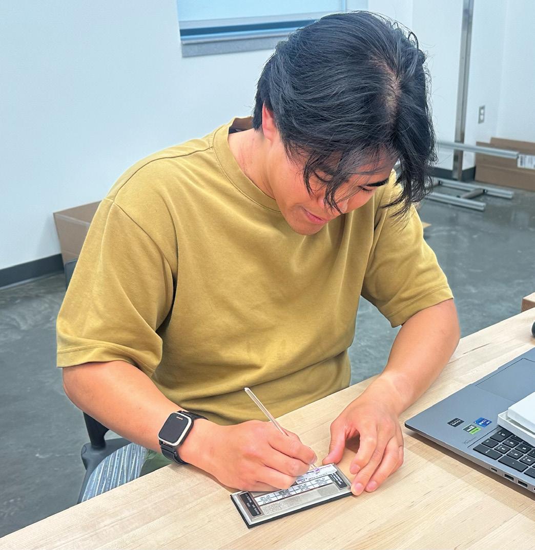
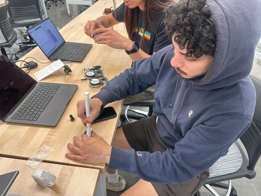
The pen-style tool with a longer spring was chosen for the final design. A longer spring was chosen to increase the travel in the pen mechanism. This increase in travel creates a larger window of appropriate pressure, allowing users to apply force far more consistently. The ball end was also reduced to the standard 8 mm to make burnishing finer surfaces more effective. It also has markings along the shaft to note where 400, 425, and 450 grams of force are being applied. When comparing the pen-style tool to the standard Testex tools, the pen tool is more reliable than the acrylic rod and the highaccuracy burnishing tool.
As for the micrometer, a linear actuator with a microcontroller and battery was decided. A
microcontroller will be used to control the speed and stroke range of the actuator. The micrometer opens and closes at a constant velocity and as there is no physical input by the user no additional force can be added to the lever. Testing resulted in similar measurements as a properly functioning micrometer.
Conclusion
Precision Solutions developed and validated two tools to improve the accuracy and repeatability of surface roughness measurements: a consistent force burnishing tool and a soft-close
micrometer. Both designs directly address common sources of human error in current field practices, including inconsistent tape imprinting and excessive measurement force. Initial testing shows that the penstyle burnishing tool produces clear, repeatable imprints, while the actuatordriven micrometer ensures controlled, consistent measurements without damaging the replica tape.
The burnishing tool achieves reliable force application through a calibrated spring mechanism and increased travel range, making it simple, durable, and effective for field use. The soft-close
micrometer complements this by automating the measurement process, eliminating user-induced variability and preserving tape integrity. Together, these tools create a more standardized and dependable workflow that aligns with the set forth requirements.
While additional refinement and testing are recommended, both solutions meet their primary objectives and demonstrate strong potential for real-world implementation. With further development, these tools can reduce costly errors, improve coating performance, and enhance confidence in surface preparation measurements for VPS and its customers.
Team CoolRoots
Team Lead
Jackson Ware
Team Members
Christopher Barrows
Nicholas Gercken
Chukwuedo Osamgbi
Sponsor Patriot Green Fund (PGF)
Faculty Advisors
Pouya Rezai
Charles White
Acknowledgements
Thomas A. Marino
Donielle Nolan
Greenhouse Water Cooling System
Problem Definition and Original Deliverables
The Presidents Park Greenhouse at George Mason University provides fresh produce year round to the campus community. During the summer months, interior greenhouse temperatures can exceed 100°F, causing the water in hydroponic supply tanks to rise above 90°F. This is well beyond the 75°F threshold at which lettuce begins bolting. Bolting is the premature flowering process that produces smaller, more bitter leaves and significantly reduces yield. Sponsored by the Patriot Green Fund (PGF), Team CoolRoots was tasked with designing a cost-effective, simple to operate, and environmentally responsible solution to maintain water temperatures within a range of 65–70°F for the greenhouse’s 100-gallon Rubbermaid BRUTE stock tanks that supply the hydroponic growing systems.
Design Requirements
The Greenhouse’s main hydroponic system recirculates approximately 80 gallons of water through 25 feet of 1-inch PVC piping across nutrient film technique (NFT) lettuce channels. Without intervention, peak summer conditions drive water temperatures far above the acceptable range. CoolRoots needed to develop a thermal management system capable of maintaining the target water temperature under worst-case conditions. They used the highest recorded outdoor temperature from July 25, 2025, in Fairfax, Virginia, which produced an estimated greenhouse air temperature of 100°F. The solution needed to address heat gain from convection with the warm greenhouse air, conduction through tank surfaces and piping, and the continuous heat input from the 25-watt recirculation pump, while aligning with sustainability goals of Patriot Green Fund.
Final Design
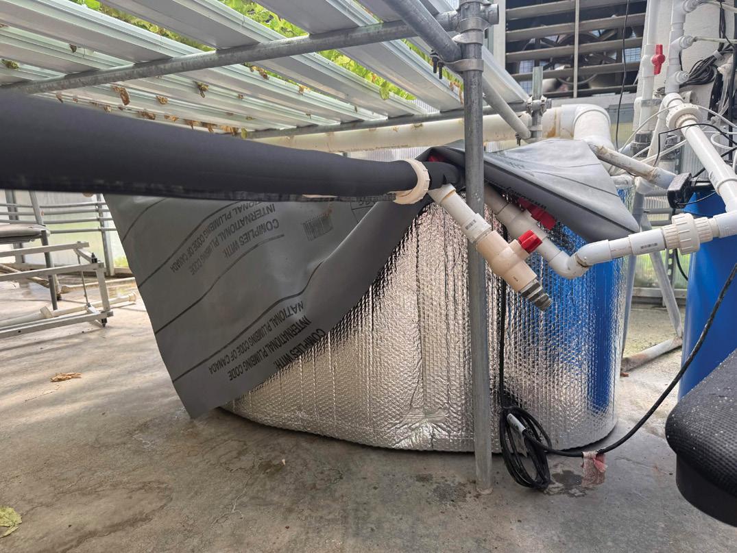
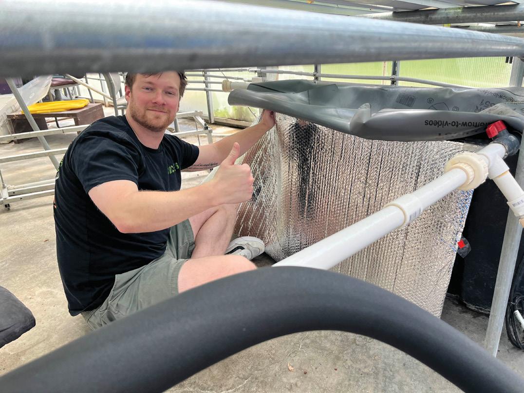
The final design combines passive thermal insulation with an active water chiller. Reflectix BP24025 reflective bubble wrap insulation (R-4.79) is applied to the sidewalls and bottom of each tank, while the existing PVC shower pan liner covers (R-0.85) remain on top to block solar radiation. Foam insulation sleeves (R-2.9) are applied to the 25-foot PVC pipe network to reduce heat gained by the water during recirculation. These passive elements significantly reduce the total cooling load that the active chiller must overcome.
The active cooling component is a Xutumm 1/3 HP water chiller utilizing R-290 refrigerant with a global warming potential of only three and an ozone depletion potential of zero, supporting PGF’s environmental objectives. The chiller recirculates water through a dedicated loop at 250 gallons per hour, returning cooled water to the tank to offset ambient heat gains.
CFD Validation
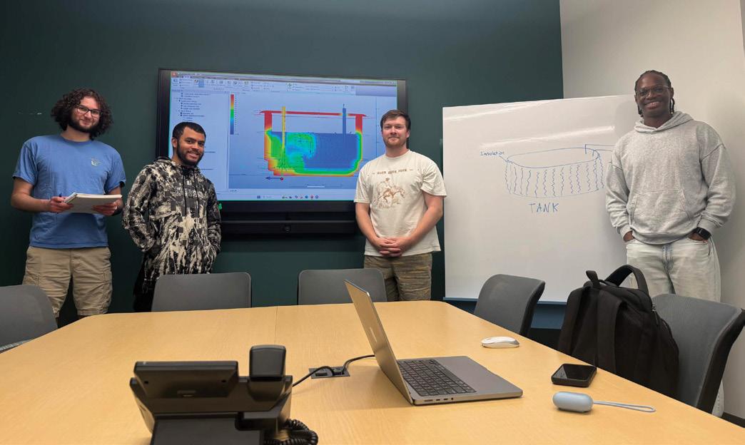
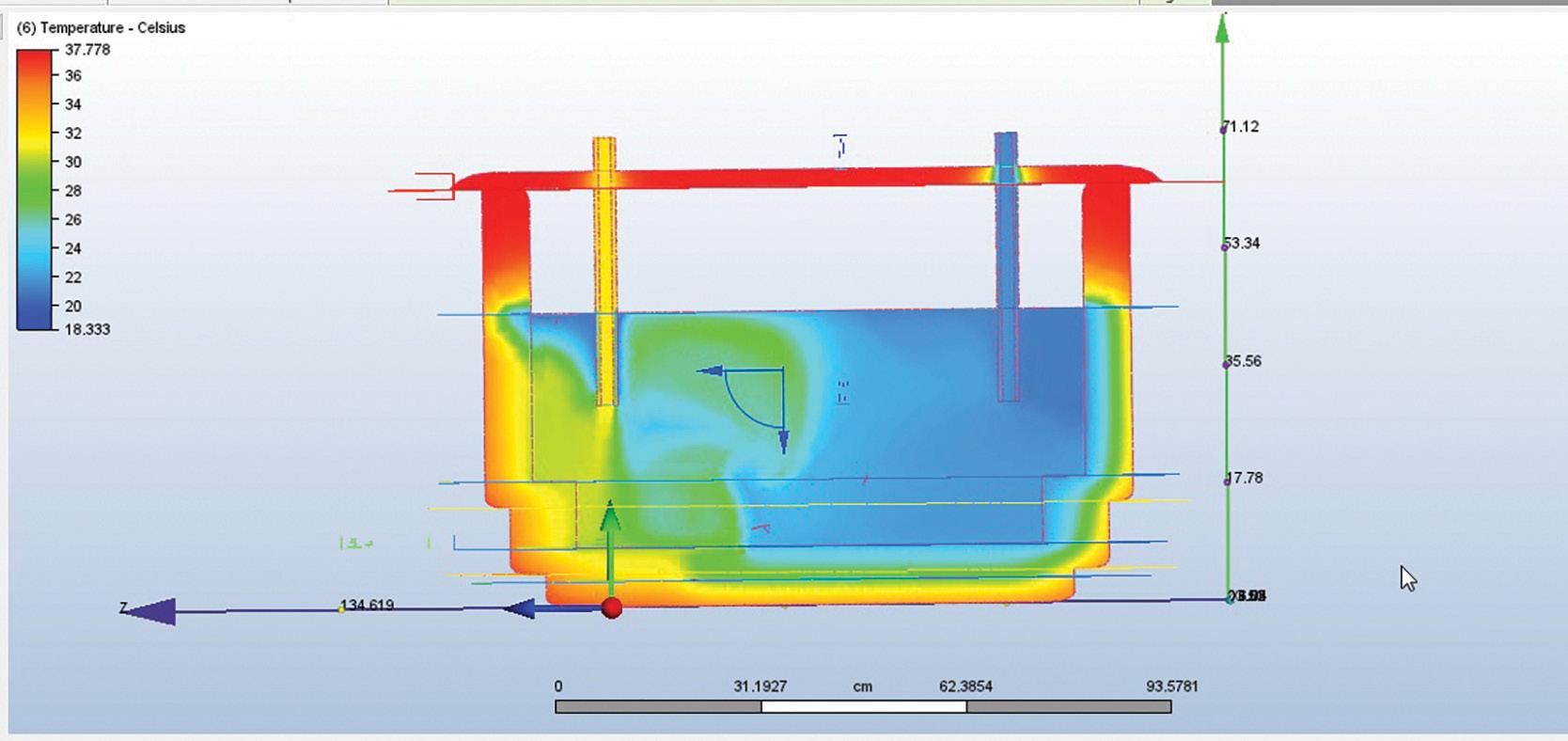
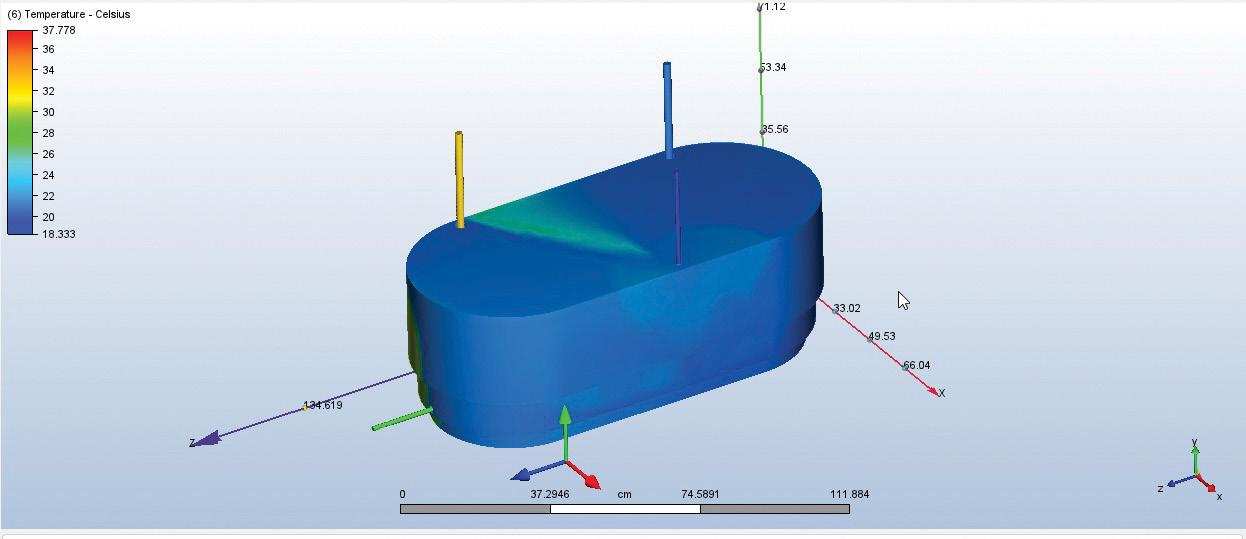
Autodesk CFD was used to simulate the 3D flow and heat transfer within the insulated tank system. The tank geometry, including inlet and outlet pipes for both the chiller recirculation loop and hydroponic supply circuit, was modeled in Autodesk Inventor and imported into CFD environment. A custom material representing Reflectixinsulated HDPE tank walls was created with a thermal conductivity of 0.0038 W/m·K, density of 40 kg/m3, specific heat of 1500 J/kg·K, and emissivity of 0.04. Boundary conditions included a chiller return inlet at 250 gal/h and 65°Fa greenhouse recirculation inlet at 150 gal/h and 90°F representing the worst-case water temperature returning from the hydroponic channels, and a film coefficient of 216 W/m2·K at 100°F on the outer tank wall surfaces. A steady-state simulation was run with flow and heat transfer enabled, with hydrostatic pressure activated and gravity set in the – Y direction (downward).
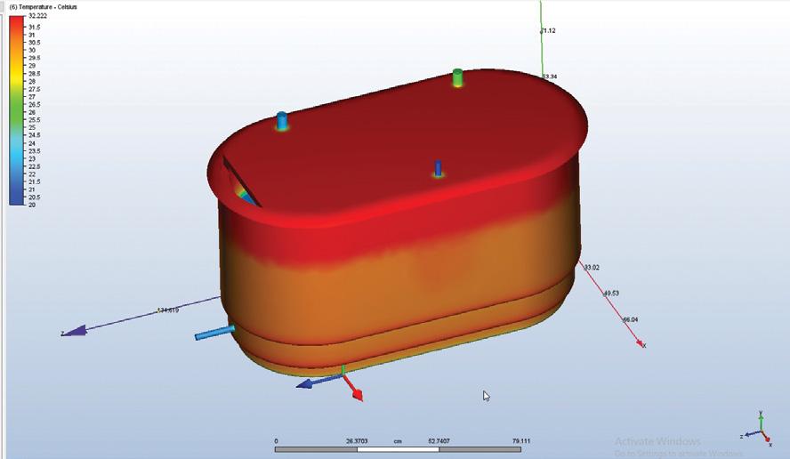
The converged simulation confirmed that the bulk water temperature remains within the 65-70°F target range. Boundary surface data showed the tank exterior at approximately 95°F, and the tank outlet averaging 69.65°F, confirming that the water supplying the hydroponic channels meets the design
target. A cross-sectional plane cut through the tank assembly revealed thermal stratification from the hot exterior through the insulation layer to the cool water interior. The contrast between the hot exterior surface and the cool water interior water volume validates that the Reflectix insulation effectively resists heat transfer while the chiller maintains the target temperature under worst-case summer conditions.
Conclusions
Through analytical modeling in Microsoft Excel and CFD simulation in Autodesk CFD, CoolRoots validated that the proposed insulation and water chiller system maintains the hydroponic tank water within the 65-70°F target range under worst-case summer conditions. The CFD simulation confirmed an outlet temperature of 69.65°F even with the greenhouse return water entering the tank
at 90°F, demonstrating that the system can overcome the most demanding thermal loads. The selected chiller exceeds the calculated sizing requirements with a comfortable margin, and the use of R-290 refrigerant satisfies the project’s sustainability goals. This solution provides the Presidents Park Greenhouse with a practical, cost-effective system to prevent lettuce bolting and improve year-round produce yield.
Figure 1: Cross Section of the Tank in CFD. Outlet on the right and inlet oan the left
Team Patriot Lockers
Team Lead
Chiemerie Udo
Team Members
Ali Aladhab
Joseph Barber
Abdulmajeed Falatah
Sponsor Patriot Green Fund (PGF)
Faculty Advisors
Colleen Berg
Nathan M. Kathir
Acknowledgements
Ben Auger
Johnnie Hall, IV
Colleen Regan
Remote Locker Control
Problem Definition and Original Deliverables
Food insecurity across college campuses is more common than most people assume. National studies indicate that a substantial number of students struggle to consistently meet their basic needs, including access to food and hygiene products. At Mason, this issue exists alongside increasing demand for support services.
Patriot Green Fund (PGF) focuses on improving sustainability and student well-being at George Mason University by funding projects that reduce waste and increase accessibility to resources. This includes the Patriot Pantry. While this resource exists, limited hours, staffing constraints, and a lack of privacy reduce accessibility for students in need.
The goal of the Patriot Lockers system is to provide 24/7 access to essential items through a fully anonymous and self-sustaining distribution system. The system has to function without requiring constant staff presence, avoid collecting personal data, and remain cost-effective for campus-wide implementation. The design must support real-time monitoring, enabling administrators to track inventory levels and usage patterns without the need for manual inspection. This functionality allows for more efficient restocking, improved resource allocation, and reduced operational overhead.
System Requirements
The system requirements were shaped by both technical constraints and the need to preserve user privacy. From the beginning, maintaining full anonymity was non-negotiable. Students should be able to use the lockers without feeling observed or identified in any way, while administrators still receive accurate and timely information about inventory levels.
The system is required to stream a live video feed of each locker’s interior, allowing administrators and users to view inventory levels in real time without requiring manual inspection. It must operate reliably within already assigned lockers, maintain stable wireless communication, and function on low voltage for safety.
Another key requirement was modularity. Each locker operates as an independent unit, allowing the system to scale across multiple campus locations without requiring redesign or additional infrastructure changes. That flexibility is what makes the system practical beyond a single prototype.
Design Selection
Three primary design approaches were evaluated during the development process. The first involved a lock-based system with user authentication, which introduced unnecessary complexity and potential barriers for students. The second relied on RFID tracking, which improved data collection but added cost, maintenance, and dependency on tagged items.
The third approach focused on a camera-based,
open-access system. This direction aligned most closely with the project’s goals. It removed user barriers entirely while still providing a reliable way to monitor locker contents.
The final system uses an integrated camera and embedded controller to stream a continuous live feed
of the locker’s interior. This approach provides immediate and consistent visibility into inventory levels while maintaining a simple and reliable system architecture. The system transmits the live feed to a centralized dashboard, enabling efficient monitoring and restocking.
Testing and Validation
Testing focused on verifying that the system performs reliably under real-world conditions. Multiple scenarios were evaluated to assess responsiveness, communication stability, and overall system consistency.
One of the key metrics evaluated was live stream stability under continuous operation. The system was tested to ensure consistent video output without interruptions or degradation in quality. Additional stress testing of the Raspberry Pi was conducted to assess performance under sustained load. Results showed that the system maintained stable streaming within acceptable performance limits, confirming that reliable real-time monitoring is achievable in practice.
Wireless transmission was also evaluated across repeated trials. The system achieved a success rate above 95 percent, with minor delays observed in cases where signal interference from the metal enclosure affected connectivity. This confirmed that while the system is reliable, environmental factors still play a role in performance.
Additional testing focused on video clarity under varying
lighting conditions. Adjustments to camera positioning and exposure settings were necessary to maintain clear visibility of locker contents. These refinements ensured that the live stream remains useful for monitoring, not just functional.
Conclusions and Future Work
The Patriot Lockers system demonstrates a practical and scalable solution for addressing food insecurity on campus. By combining simple hardware with automated monitoring, the system provides continuous access to essential resources without requiring user identification or constant staff involvement. Its streamlined design eliminates unnecessary complexity while maintaining reliability and ease of use.
The system also supports sustainability goals by repurposing existing lockers and reducing waste associated with inefficient inventory management. Overall, the design meets its intended objectives while remaining cost-effective and adaptable for future expansion.
Future improvements include integrating machine learning and AI to analyze live video streams and automatically identify items within each locker, reducing the need for manual monitoring and enabling automated restock alerts. Additionally, the modular design supports expansion across multiple campus locations, allowing the system to scale into a broader network of lockers serving student needs.
Team Drop Force Dynamics
Team Lead
Edwin Santos
Team Members
Nadia Carr
Jessie Cortez
Jessica Vito
Jared Williams
Sponsors
Office of Naval Research (ONR)
Naval Surface Warfare Center Carderock Division (NSWCCD)
Faculty Advisors
Mehdi Amiri
Colton Talley
Acknowledgments
Maureen Foley
Johnnie Hall, IV
Nathan M. Kathir
William Manning
Brandon Newsome
Instrumented Drop Tower Upgrade
Problem Definition and Deliverables
A drop tower is an essential tool for materials testing that measures impact force and velocity. The Naval Surface Warfare Center Carderock Division’s (NSWCCD) existing drop tower is not ASTM D7136 compliant, limited to testing 4x6-inch samples, and does not measure and record velocity or force during testing. The goal of this project is to meet ASTM D7136 standards by upgrading the tower base to support larger composite samples and integrating sensors capable of recording and storing data. An upgraded drop tower design will enhance NSWCCD’s testing capabilities by allowing more accurate testing of a wider variety of samples, which can later be used in various applications, such as ship hulls and protective panels.
Design Requirements
NSWCCD asked Team Drop Force Dynamics to design and fabricate an upgraded base for their existing drop tower capable of supporting composite samples up to 16x16 inches, with an unsupported 14x14-inch impact zone. The new base must withstand repeated impact loads without failure or deformation from repeated testing over a sustained period. Additionally, the team was tasked with integrating a sensor system to record and store key measurements, including impact force and velocity. The system must be capable of reliably recording and storing data from multiple tests. All design and fabrication are needed to adhere to ASTM D7136 standard for drop weight impact testing.
Final Design Sensor and Software Integration
The Sensor and Software Integration system consists of a Raspberry Pi 5, a Teensy 4.1 microcontroller, a throughbeam slot sensor (EE-SX1070), and two flags on the impactor. When the flags pass through the slot sensor, the Teensy 4.1 will collect the data from the slot sensor, which has an exceptionally high signal-to-noise ratio to ensure reliable object detection, and send the data to the Raspberry Pi 5. The data from each test will be stored within the Raspberry Pi and copied into MATLAB to display the velocity and force graphs. A custom MATLAB application is included to ensure seamless data transmission and display from the Raspberry Pi to a laptop or desktop.
Tower Base Upgrade
The Tower Base Upgrade features a reinforced foundation forming two subsystems: a rigid base frame and the specimen clamping assembly. The frame is constructed from A36 structural steel, providing a robust
vertical base designed to withstand repeated impact loads. This subsystem serves as a critical interface, adapting the existing top plate to the new base. The clamping assembly uses a dual-plate configuration featuring a 0.5 inch and 1-inch thick steel plate, engineered to accommodate specimens in accordance with ASTM D7136 standards. An eight-bolt system is employed to secure the assembly, ensuring consistent conditions and preventing displacement during testing.
Fabrication and Assembly
Due to size constraints, manufacturing the base was a challenge. First, the team had to ensure that all measurements for the holes matched the original drop tower at the NSWCCD lab to allow for a smooth installation of the new rigid base. A step drill bit was used to drill accurate hole diameters and allow for ½” -13 threaded connections to be aligned. This was the optimal way to minimize material deformation and ensure consistency. Our assembly utilizes ½” -13 wing nuts with 2-inch fully threaded screws and 2.5-inch partially threaded hex drive screws. These were selected to ensure sufficient clamping force while being easy to assemble and adjust as needed. The use of uniform threading allows for the installation process to be easier and to disassemble and reassemble using standard tools.
Analysis, Testing, and Validation
Sensor and Software Integration
The initial testing phase started with the fabrication of a circuit by utilizing a breadboard along with all the electronic components, controllers, and sensors. A prototype double-pronged flag system was then 3D printed to simulate the free fall of the impactor on the current, full-scale drop tower system. This prototype was used to develop the code within the Raspberry Pi interface that would calculate the velocity and impact force. The flag system also let us ensure the system’s accuracy was within the required standards and ensured that communication to MATLAB was reliable.
Tower Base Upgrade
To ensure the upgraded rig meets the demands of ASTM D7136, the team performed a multi-stage validation process. Nonlinear Dynamic FEA was used to model the impact of 16.99-lb tup on both A36 Steel and Orthotropic CFRP specimens at velocities up to 13 m/s. Through iterative simulation, the clamping assembly was refined with a 1.0 in. thick base plate, which reduced the stress by 78 percent compared to the first design. Physical testing confirmed the stability of the frame, confirming its ability to deliver 161.4 ft-lbs. of energy while supporting a safety factor of 3.18.
Conclusion and Future Work
Drop Force Dynamics successfully designed and fabricated an upgraded drop tower base capable of supporting composite samples up to 16x16 inches in addition to the previously supported 4x6-inch samples used in impact testing. The new base complies with all ASTM D7136 standards for design and testing. In addition, the team successfully developed a sensor system prototype capable of reliably recording and storing key data, including velocity and impact force, across multiple trials. This prototype is easily scalable to a fully functional model and will be integrated into the fully assembled drop tower system at NSWCCD.
Team VPRT
Team Lead
Efrenn Chavez
Team Members
Aaron Berthiaume
Cooper Ellis
Dillon Harms
Avani Sharma
Sponsors
Office of Naval Research (ONR)
Naval Surface Warfare Center Carderock Division (NSWCCD)
Faculty Advisor
Mehdi Amiri
Acknowledgements
Josh Dunn
Maureen Foley
Johnnie Hall, IV
Nathan M. Kathir
William Manning
Nikki Van Nostrand
Charles White
Vent Pipe Corrosion Upgrade Kit
Problem Definition and Original Deliverables
Aboard U.S. Navy Destroyer-class ships, several small issues compound the difficulty of repairs and maintenance for pipe caps, lengthening repair times and increasing required labor. A new layer of paint is frequently applied across much of the ships’ decks. This is because of the environment the ships are exposed to, the paint fades, chips, and begins to flake because of the sea spray, sun damage, and fumes from the tank vents. This paint can build up in layers up to a quarter-inch thick, making the repair of components located on deck difficult. Corroded and broken fasteners, as well as damaged retainer caps make the removal and replacement of screens difficult.
VPRT was tasked with creating a repair toolkit for a vent pipe assembly installed across several U.S. Navy Destroyer-class ships. The Naval Surface Warfare Center Carderock Division (NSWCCD) also asked the team to conduct material research to determine if there could be a different material with which to replace the current fasteners and create a flow chart to ensure streamlined repairs in the future. VPRT was concerned specifically with flame arrestor assemblies, which help to vent fumes from various sources on the ship.
Requirements
The project requires four objectives to repair the vent cap assembly and improve the maintenance process. First, to address the excessive paint layers, the team was asked to propose a cutting method and tool for slicing coated around the pipe vent cap.
1. First, to address the excessive paint layers, the team was asked to propose a cutting method and tool for slicing coated around the pipe vent cap.
2. Second, for the corroded and broken fasteners, VPRT was asked to propose a streamlined method and create a toolkit made of off-the-shelf tools for fastener removal, as well as a 3D-printed drill guide to enable these repairs to be conducted easily since the pipe vents are upside down.
3. For the third objective, the team was asked to investigate an alternative fastener material with more corrosion resistance than the current stainless-steel fasteners and with the same physical dimensions such that they can be easily replaced.
4. The final objective is to create a 3D-printable retaining cap for the vent in case the permanent stainless-steel retainer is damaged or lost.
VPRT was provided criteria and information from NSWCCD with direct guidance from Dr. Maureen Foley.
Fastener Removal Approach Development
For the second objective concerning removal and repair of damaged fasteners, the team compiled a list of off-the-shelf tools based on research on corroded bolt removal and repair strategies. To assist with future
repairs, VPRT has created a drill guide that fits onto the end of the flame arrestor. This drill guide has multiple holes of different sizes to fit drill bushings that would ensure the best repair angle is met. The point of the drill guide is to make fastener removal and installations easier for the person repairing the flame arrestor, particularly in the upside-down orientation of the vent cap.
Testing Results and Analysis
The team conducted a series of tests that allowed the validation of many project requirements and raised many necessary design changes. The team heat tested both the new fastener materials and the 3D-printed replacement cap to ensure usability in hot climates. The new fastener materials were corrosion tested and examined under a microscope to validate their improved corrosion resistance and were torque tested to see at what torque the fasteners fail. The fastener removal tools were tested to remove damaged and snapped fasteners and to repair the threads inside the cap head. Lastly, the
paint cutting tool was tested to find the best method for cutting paint around the edge of the cap.
Conclusion
This project emphasized real-world application, availability, and practicality over the development of a completely new design. While VPRT initially aimed
to create a more robust and complex solution, the sponsor’s guidance and project requirements directed the team toward improving and adapting an existing design. As a result, the team focused on material strength, rigidity, and performance in realistic operating conditions. Although the project faced budget-related challenges due to government funding
cuts affecting the sponsor early in the process, VPRT demonstrated strong communication, adaptability, and problemsolving throughout the project. These efforts allowed the team to obtain testing materials and continue working toward the original objectives without compromising the project’s intent.
Team VOXEL
Team Lead
Thomas Carnogursky
Team Members
Daniel Hebert
Rebeca Romero
Noe Rubio-Ramirez
Sponsor
Aeronautical Systems Incorporated (ASI)
Faculty Advisor
Charles White
Acknowledgements
Bruce Andersen
Diego Bell
Kevin Casteel
Josh Dunn
Johnnie Hall, IV
John Hoblack
Michael Kamel
Michael McFadden
Kelly Sadel
Photo Booth for Aircraft Parts
Problem Definition and Original Deliverables
Aeronautical Systems Inc. (ASI) works with aircraft parts for the government and needs a new machine to help standardize the process of imaging parts for reference and quality assurance. Currently, ASI’s process involves having whoever is handling the part use their phone to take photos for reference. To standardize the process, ASI wants a machine that can take pictures of the aircraft parts. The machine needs to be able to move the part so every side can be photographed, and it cannot run on cloud services to maintain cybersecurity requirements from the government. Additionally, it should have a scale as part of the image for size reference and lighting. A photobooth solution was proposed that has an operator to place an aircraft part in the booth, run the program that captures a standardized series of images, and saves them to an SD card for their needs.
System Function
The frame would be designed after a cube to make a symmetrical space for clear images while providing convenient access for setup and components to run the machine. To help standardize the process, each aircraft part would be treated as a cube, which requires six images to fully capture a part. A camera would be placed at the top, one side, and the bottom of the cube, all pointed at the center baseplate where the aircraft part would rest. The center baseplate would then be rotated via motor during the imaging process so the side camera can capture all sides of the part. All this would be managed by the control panel, where the images would be saved to an SD card.
Design
The photobooth concept for aircraft parts isn’t commercially available, so designing one for ASI requires fabrication of some custom parts but mostly modifying many commercially available parts. The frame was built from 2020 extruded aluminum, so commonly available extruded aluminum components and attachments could be used for assembly. The baseplate would modify a lazy Susan bearing, so a transparent acrylic plate would attach to the exterior bearing edge while the interior edge attaches to the aluminum frame. A stepper motor with a belt attached to the lazy Susan’s outer bearing edge could then rotate the part with precision for consistent images. The cameras and software are Nvidia Jetson Orin Nano-based and can be modified to meet ASI’s requirements. Lastly, lighting would be on the interior edges pointed, and the center with plastic panels fitted between the frame sections to help with lighting and remove inconsistent backgrounds.
Fabrication
The frame, motor, and lighting required the least number of trials to develop; the initial setup proved capable throughout the fabrication process. The camera and software systems proved to be the most challenging part of the project. Initial attempts to adapt Arduino Uno or Mega to run the prototype kept running into hardware limitations. Solutions to overcome these limitations would be reached but produce an unsatisfactory quality image. Other solution attempts would work, but when made to full scale, they introduced data loss and other hardware limitations of the Arduino. Though a minimum viable product was achieved, it was decided to switch to the Nvidia Jetson Orin Nano and eightmegapixel Arducams as the new software and camera systems for the prototype. Through a touch screen display, the Jetson would use its camera-specialized software to simultaneously run the three cameras and the Arduino Uno that operates the motor. Once the
program was initiated, the motor Arduino would synchronize with the top, bottom, and side camera so that a top, bottom, and one side image would be taken. Then the motor would rotate the baseplate until another side is visible for another picture to be taken from the side camera. This would repeat until the part was fully photographed and saved to an SD card in JPEG format, where the operator can retrieve the SD card for ASI’s needs or repeat the process for another aircraft part.
Conclusion and Future Work
The prototype made by Team VOXEL meets the requirements set by ASI and provides the company with a machine
that standardizes a part of the quality assurance process. Possible improvements in the future are to make the frame more space efficient, as a complete cube is not necessary for functionality. The cameras can be upgraded to a more powerful version from the current eight megapixels to further improve the usefulness of the images. The overall size of the prototype could be modified to make it more space
efficient with further development. Specialized functions could also be implemented in the software so that the user could have more control over the cameras with live monitors of what the camera sees. VOXEL had possible improvements in mind during development and created the prototype such that any changes can easily be implemented into the machine.
Team Thermal Solutions
Team Lead
Andres Cruz Guzman
Team Members
Meryem El Kasbi
Sayed Noormal
Mihiret Tolessa
Nicolo Miguel Ulit
Sponsor Amazon Web Services (AWS)
Faculty Advisor
Jeffrey Moran
Acknowledgements
Johnnie Hall, IV
Saanyol Igbax
Sajad Kargar
Nathan M. Kathir
Ajay Sunkara
Krista Tran
Charles White
Data Center Heat Loss Recovery and Geothermal Cooling Integration
Problem Definition and Original Deliverables
As data centers continue to expand across Northern Virginia, the large amounts of waste heat they generate present both operational challenges and an opportunity for energy reuse. Team Thermal Solutions was tasked with developing a method to capture and repurpose this waste heat in a controlled and efficient manner. The proposed solution is a geothermal cooling system that captures hot exhaust air from a data center’s hot aisle and plenum and rejects the heat into the ground through a closed-loop fluid system, with the cooled air then redistributed to non-critical spaces like break rooms and offices. The system works by passing hot air through a fin heat exchanger where it transfers heat to a waterbased coolant, which then circulates through buried copper ground loops that dissipate the heat into the soil before returning to repeat the cycle. The system is designed with objectives of reducing exhaust air temperature and enabling its reuse in a non-critical space such as offices and break rooms.
The rate of heat transfer in a tube can be described by,
q = mcp (Tout – Tin)
Here, . m is the mass flow rate of the cooling water, cp is its specific heat, and Tout and Tin are the temperatures of the water leaving and entering the tube, respectively. Using this equation, we can determine the rate of heat release by the water into the soil by measuring the temperatures at the entrance and exit.
Prototype Design and Experimental Setup
To evaluate the feasibility of this concept, a physical prototype was constructed. The system consists of a chest freezer filled with soil to simulate subsurface thermal conditions; copper piping arranged as a ground loop, circulation pump, and a finned heat exchanger. The chest freezer serves as a controlled environment to approximate ground thermal mass and insulation effects. Copper was selected for piping due to its high thermal conductivity, which enhances heat transfer between the coolant and surrounding soil. A closed loop configuration was implemented to ensure consistent fluid properties, prevent contamination, and maintain controlled heat transfer conditions. The experiment setup allows for observation of temperature changes in the coolant and surrounding soil, providing insight into the system’s ability to dissipate heat over time.
Fabrication of Deliverable
The fabrication of the geothermal cooling system involved several standard machining and joining processes. Copper pipes were cut to the required dimensions using a machine shop band saw. These pipes were joined to each other by lathering a petroleum-based flux around the outside circumference near connecting pieces and then brazing a piece of steel
solder onto them. Following the fabrication, deburring and cleaning of all pipe ends were performed to reduce flow resistance, improve handling safety, and ensure proper surface condition for brazing. This preparation enhanced joint integrity and minimized the risk of leakage, contributing to overall system reliability. The completed fluid loop assembly was then integrated with the circulation pump and heat exchanger to form a closed loop cooling system.
Key Features of Design
The key performance indicator was the thermal behavior of the coolant as it travels through the geothermal loop. Temperature sensors called K-type thermocouples placed throughout the loop onto the pipe exterior allowed the team to record the changes in temperature
of the coolant as it traveled throughout the loops. Further analysis was done at the plenum, where the team recorded the temperature of the air exiting the heat source, air as it traveled through the heat exchanger, and the inlet/outlet coolant temperatures. The equipment that allowed the experiment to run was the chest freezer and the pump.
Computer Aided Design (CAD) Analysis
The heat exchanger geometry was developed in SolidWorks to support CAD analysis. The model consists of copper coolant tubes, aluminum cooling fins (cooling plates), the U-shaped pipes that join the fluid carrying tubes, supporting rods and plates that provide stability and hold the pipes together, and static. The heat exchanger is known as the finned-tube heat exchanger and is widely considered as an efficient assembly that maximizes heat transfer between the working fluid and surrounding air. Copper was selected due to its high thermal conductivity, while thin aluminum fins were used to increase the rate of convection due to the increased surface area. In preparation for CFD analysis, noncritical components of the assembly such as supporting rods and supporting plates were removed.
The fins were modeled as repeated thin plates to increase convection surface area, and the tubes were designed to maintain a continuous internal flow. For the primary iterations, the geometry was simplified significantly to reduce computational cost while preserving heat transfer surfaces. For instance, only half of the number of fins (reduced from 55 to 26) with increased distance between each successive fin were placed in the assembly to accommodate the limitations in meshes sizes and numbers for a student license in ANSYS.
Computational Fluid Dynamics (CFD) Setup
CFD analysis was performed using ANSYS Fluent to evaluate the thermal performance of the heat exchanger through a conjugate heat transfer simulation. For the simulation, the energy equation along with a pressure-based steady-state solver were enabled to model the heat transfer between the fluid and solid regions. The model was classified into fluid domains for coolant flow and external air, as well as solid regions representing tubes and fins.
Velocity inlet boundary conditions were applied based on expected data center operating conditions, with a inlet air temperature, while pressure outlet conditions were applied at the exists. A tetrahedral mesh was generated with fine mesh at the critical regions (point of contact of fins and tubes), while coarser meshed regions were used away from heat transfer surfaces to reduce computational cost.
The CFD model serves as a validation figure for the
experimental prototype and provides guidance for optimization and future designs. The preliminary results indicate an increase in temperature distribution across the fin surfaces, confirming effective heat transfer from the hot air stream into the coolant loop. Temperature contours demonstrated the change in temperature gradient as the fluid makes it way towards outlet throughout. Future work will focus on mesh refinement and increasing the number of fins to improve and optimize heat transfer performance.
Conclusions and Future Work
Data centers consumed approximately 240-340 terawatt hours of electricity globally in 2022, accounting for roughly 1-1.3 percent of total global electricity demand, with projections suggesting this could reach 800-950 terawatt hours by 2030 due to the growth of artificial intelligence and cloud computing (International Energy Agency, 2023; 2024). Since cooling represents a major portion of this energy use, improvements in cooling efficiency can produce meaningful cost reductions over the life of a facility. Strategies such as waste heat recovery and geothermal cooling have the potential to lower energy consumption, extend equipment lifespan by reducing thermal stress, and decrease operational costs over time. Environmentally, reducing the electricity required for cooling directly lowers indirect carbon emissions, while waste heat recovery reduces the need for traditional heating fuels and geothermal cooling limits reliance on water intensive evaporative systems and high global warming potential refrigerants (ASHRAE, 2021). From a societal standpoint, lower cooling energy demand reduces stress on local power grids, improving reliability for surrounding homes and businesses, while repurposed waste heat can support heating for nearby buildings and communities. Additionally, the adoption of these advanced cooling technologies can create new job opportunities in engineering, construction, and energy systems, ensuring that data center expansion does not come at the cost of local resources or community wellbeing.
Team
SmartLouvers
Team Lead
Charles Go Cabo Chan
Team Members
Kim Bach
Christopher Kaplan
Joshua Nguyen
Sponsor Amazon Web Services (AWS)
Faculty Advisor
Sajad Kargar
Acknowledgements
Josh Dunn
Ming Feng
Johnnie Hall, IV
Ajay Sunkara
Krista Tran
Smart Adaptive Outside Air Intake Louver
Problem Definition and Original Deliverables
Modern data centers face increasing cooling demands, requiring large volumes of outside air while maintaining protection from environmental conditions. In cold climates, snow intrusion poses a major risk, as it can melt, refreeze, clog airflow, and potentially lead to overheating or system shutdowns. Current systems used by Amazon Web Services (AWS) rely on static louvers, such as the Greenheck ESD-435, which are designed to balance airflow and weather protection but cannot adapt to changing conditions. This results in limited airflow during normal weather and insufficient protection during snow events, increasing both energy consumption and operational risk.
To address these limitations, Team SmartLouvers has partnered with AWS to develop an adaptive louver system capable of automatically adjusting blade angles based on real-time weather data. The system must maximize airflow under normal conditions to improve cooling efficiency, while reducing or preventing snow ingress during adverse weather. Additionally, it should operate without manual intervention, enhancing system reliability, and providing consistent environmental protection for data center infrastructure.
Design Requirements and Approach
The team based the adaptive system on the Greenheck ESD-435 louver, which is known for its strong aluminum construction and air-efficient blade shape. Using this existing frame allows the team to focus on adding mechanical motion and weather sensing instead of designing a brand-new louver. Several design requirements shaped the project. The SmartLouver has to maintain at least 250 cubic feet per minute of airflow when open and keep its pressure drop within a 20–50 pascal range. It also needs sensors to detect moisture, air temperature, and pressure so the system can tell when snow or freezing conditions were present. All components are designed to operate safely using 24 VAC power and integrate into AWS’s HVAC systems without major modifications. Mechanically, the system uses a 90 inch-pound damper actuator that is linked to all blades via a vertical linkage bar. The actuator is powered through a 24-volt step-down transformer, ensuring compatibility with the available power supply while maintaining safe operation. This actuator can move the blades smoothly to varying angles and provides enough torque to overcome added resistance from snow or ice. Control signals come from a 0–10 V I2C DAC module connected to an Arduino microcontroller. The Arduino receives data from two sensors: an LM393 precipitation sensor and a waterproof DS18B20 temperature sensor. Together, these components allow the system to detect precipitation and determine whether outdoor conditions are consistent with snowfall.
Final Design
The final SmartLouver design improves both airflow control and protection from weather. A vertical bar connected to each blade ensures that all blades move together through simple linkages, improving reliability while minimizing maintenance. The damper actuator allows partial opening, giving the system flexibility to balance airflow and protection as conditions change. For sensing, the system determines snowfall by combining inputs from both the precipitation sensor and the temperature sensor. Since the precipitation sensor only detects the presence of precipitation and cannot distinguish between rain and snow, temperature data is used as a secondary condition. When precipitation
is detected and the ambient temperature falls below freezing, the system identifies the event as snowfall and responds accordingly. This dual-sensor approach allows the system to close early during snow events while remaining open during safe conditions, improving reliability compared to single-sensor designs. The overall design is modular and easy to scale. All components use standard mounting hardware, common wiring, and widely available electronics, making the system suitable for integration across multiple AWS facilities.
Fabrication
Fabrication begins with disassembling the ESD-435 stationary louver to allow for geometric modifications. Six ½-inch holes, spaced 3 ¼ inches apart, are precisely drilled into the sides of the frame to accommodate the new mechanical components. Blade clamps are then secured to each louver blade using set screws, ensuring stable positioning while allowing controlled movement. These clamps are connected to housed bearings, which are fixed to the side frames by welding them in place, reducing friction
and minimizing wear over the operational lifespan of the system.
A custom-fabricated vertical linkage bar is designed to match the exact dimensions of the louver assembly. Each blade clamp is connected to this bar, enabling synchronized movement of all blades through a single actuation mechanism. Finally, a 90-inch pound actuator is mounted near the bottom side of the louver and linked to one of the blade clamps. This actuator serves as the primary driving force, translating rotational motion into coordinated blade adjustment.
Testing and Implementation
Testing focused on airflow performance, environmental response, and actuator behavior. A large industrial fan provided airflow while pressure, temperature, and air velocity were measured with sealed ducts to prevent leaks. Arduino software recorded data to confirm airflow and pressure requirements were met. Environmental testing used simulated snow placed on the louver. The sensors were monitored to verify that the system detected precipitation and responded by closing the blades. Future tests will include
simulations, snow-intrusion studies, and long-term environmental evaluations.
Conclusions and Future Work
SmartLouvers help data centers cool more efficiently and safely. In clear weather, they open fully to increase natural airflow, reducing reliance on mechanical chillers. During snow events, they partially close automatically to prevent moisture damage and airflow blockage. Their simple, modular design supports easy installation across many sites. With further testing and refinement, SmartLouvers offer a strong solution for colder region cooling challenges.
Team Sea Sense
Team Lead
Rasean L. Boyd
Team Members
Parag Barua
Basim Mohamed Felfel
David C. Lancaster
Brian M. Portillo
Melendez
Sponsor
RobotX (Registered Student Organization)
Faculty Advisors
Van Jones
Leigh McCue
Acknowledgments
Vanessa Barth
Johnnie Hall, IV
Nathan M. Kathir
Krista Tran
Pioneering Portable Maritime Autonomy
Problem Definition and Original Deliverables
Autonomy in marine robotics has become increasingly more prevalent with research and competitions advancing real world applications. This is due to autonomous maritime vehicles being able to navigate and complete tasks on the water with limited human control. These innovations have made for better safety, efficiency, and overall capability when accomplishing maritime missions. Team Sea Sense was tasked with applying these ideas to the SS Otter, a small catamaran-style vessel developed by a previous capstone team. While the boat had basic remote-control capability, it was not yet prepared for more advanced autonomous operation.
To move the platform’s capabilities forward, the team set out to deliver a portable autonomy package that provides the SS Otter with basic autonomy functions. This included developing and integrating the main sensing and control systems, creating a protected electronics setup for marine use, adding safe control features such as manual override, and carrying out testing that could show the platform was ready for basic autonomous tasks.
Design Approach
Team Sea Sense used a shared control approach for the boat’s autonomy system. A Jetson computer handles higher level tasks such as sensor processing and decision making. A Pixhawk flight controller handles lower-level control and sends commands to the thrusters. This setup keeps the system organized and makes it easier to separate decision making from direct motor control and allows for switching between autonomous and manual control.
The team also focused on modular design. Instead of creating a system that only works for one exact setup, they aimed to build an autonomy package that could be adapted to similar vessels in the future.
Major Systems
The Sea Sense platform combines several key systems. For above water perception, the boat uses a LiDAR sensor and a camera. These sensors allow the vessel to detect nearby objects, identify specific markers, and support navigation. The LiDAR helps the boat understand the distances of its surroundings, while the camera provides visual information that can help identify targets such as buoys.
For propulsion, the vessel uses a skid steering setup with two thrusters. By changing the power sent to the left and right sides, the boat can move forward, reverse, and turn. This gives the platform maneuverability without requiring a separate rudder. It also keeps the mechanical setup relatively simple.
One of the most unique parts of the project is the sonar system. The team created custom hydrophones to detect known underwater frequencies. These sensors are designed to estimate the direction of sound. The detected frequency then determines the behavior of the SS Otter. This gives the platform another way to sense its environment and makes the project stand out from a standard surface navigation system.
The project also includes a waterproof electronics enclosure. Since the boat carries sensitive electronics, this enclosure is essential for protecting the hardware from splashing water and outdoor exposure. A reliable enclosure is important for both performance and safe operation during testing.
Testing and Validation
Testing has been a major part of the Sea Sense project. Since on-water testing is time consuming and adds more risk, the team created a small land-based test platform called the Green Goblin. This platform has been used to test communication, control behavior, and parts of the autonomy system in a safer and simpler setting before moving to the SS Otter.
Testing showed that the autonomy system successfully operated as intended. The boat was able to detect specific markers and navigate to them, demonstrating that the sensing, control, and propulsion systems could work together in a meaningful way. This was an important accomplishment as it showed
that the platform was capable of more than just basic remote operation and could carry out core autonomous tasks on the water.
The sonar system also went through early testing. The team confirmed that the manufactured hydrophones could still detect sound after being encased in resin, which showed that the concept was practical and worth continuing. The sonar system worked successfully in a wild environment during on-boat testing, confirming that the sensors could operate after waterproofing and still provide useful underwater detection capability.
Conclusions and Future Work
Future work will focus on expanding the system’s autonomy and overall capability. This may include adding additional sensors to improve environmental awareness and system reliability. The team hopes to implement path-finding algorithms so the boat can make more advanced navigation decisions and move effectively
through its environment. Along with these improvements, continued testing will help refine system performance, waterproofing, and overall reliability. These next steps will help build on the current platform and give future teams a stronger foundation for competition purposes.
Team MechArena
Team Lead
Abbas Hussain
Team Members
Shreyes Kumar
Triet Lieng
Abraham Valencia
Sponsor
Professor Daigo
Shishika
Faculty Advisor
Daigo Shishika
Acknowledgements
Kentaro NojimaSchmunk
Krista Tran
James Yang
Robo Game Arena
Problem Definition and Original Deliverables
As autonomous systems continue to become more integrated into everyday life, there is growing interest in how robots can interact not only with their environments, but also with humans and with each other in competitive and cooperative settings. While many robotics projects focus on navigation, manipulation, or sensing alone, fewer systems explore how physical robot behavior can be used as a medium for strategy, deception, and signaling. This project addresses that gap through the development of Robo Game Arena, a human-playable tabletop robotics platform designed for both interactive gameplay and future research in game theory and multi-agent systems.
The objective of the project was to design and fabricate a complete game arena in which multiple player-controlled robots compete to collect and deposit colored tokens while operating under hidden objectives and strategic constraints. The system was intended to function as both a capstone prototype and a research test bed that could later be used to investigate how motion and robot actions communicate information in the absence of direct verbal interaction. The original deliverables included a modular tabletop arena, a set of compact mobile robots with token collection mechanisms, a visionbased scoring system, a user interface for tracking player scores, and the physical and software infrastructure necessary to support full gameplay.
A major design requirement was that the platform needed to be human-playable, visually engaging, and easy to demonstrate, while also being robust enough to support repeated testing and design iteration. The final concept emphasizes accessibility, modularity, and experimental flexibility, allowing the game environment, scoring rules, and obstacle arrangement to be adjusted for future development.
Design and Development Collaboration
Robo Game Arena was developed by Team MechArena as part of the Mechanical Engineering senior design program at George Mason University. The project was completed under the sponsorship and mentorship of Daigo Shishika. Team collaboration was essential throughout the design process, as the project required the integration of mechanical design, fabrication, electronics, controls, and computer vision.
The development process began with concept generation and rule refinement. Multiple game formats were evaluated before converging on a competitive token-collection structure that balanced strategic depth with practical implementation. From there, the project evolved through repeated prototyping of the robots, arena, and sensing architecture. Team members worked collaboratively on mechanical fabrication, CAD modeling, electronics integration, software development, and system testing. Communication and coordination were supported through regular design reviews, advisor meetings, and iterative demonstrations of subsystem progress.
One of the key strengths of the project was its interdisciplinary nature. Mechanical design decisions influenced gameplay, while software and sensing limitations directly affected arena layout and robot
behavior. As a result, the project required continuous coordination between hardware and software development to ensure the final system worked as a cohesive whole.
Fabrication and System Implementation
The Robo Game Arena consists of three primary subsystems: the arena, the robots, and the vision and scoring system. The arena was designed as a modular 48×48-inch platform that fits on a folding table for easy transport and demonstration. Physical features such
as walls, speed bumps, and team bases were fabricated and arranged to create an interactive play environment that encourages navigation challenges and strategic decision-making.
The robot platform underwent multiple design iterations before reaching the final prototype. Each robot was designed to be compact, maneuverable, and capable of collecting and transporting tokens efficiently. A custom arm mechanism with an electromagnet end effector was used to pick up tokens fitted with metal washers. Significant effort was dedicated to improving the speed, consistency, and reliability of token collection, since this function directly impacts gameplay quality. Through repeated testing and refinement, the team finalized a robot design capable of collecting a token and depositing it into a designated base successfully.
To support autonomous scoring and system monitoring, an overhead camera was incorporated into the platform. Using computer vision techniques, the camera detects colored tokens and tracks gameplay events in real time. A referee and scoreboard
interface was developed to update player scores based on token collection and deposit events. This integration of hardware and software was demonstrated successfully during advisor review, where the robot collected a token, deposited it into the base, and triggered the software to update the appropriate player score. This demonstration validated the core functionality of the platform and showed that the overall game concept is feasible.
Conclusion and Recommendations for Future Work
The Robo Game Arena project demonstrates that a compact robotics platform can successfully combine mechanical design, electronics, controls, and vision-based software into a functional and engaging multi-player system. The final prototype shows strong potential not only as a capstone demonstration platform, but also as a foundation for future research into signaling, strategy, and decision-making in robotic systems.
Future development of the Robo Game Arena will focus on enhancing both gameplay and system interactivity. One potential improvement includes integrating a projector system to display dynamic visuals directly onto the arena surface, enabling
real-time feedback, player information, and interactive game elements. Additionally, incorporating more advanced actuators and sensors into robots could allow for richer and more complex gameplay, improving precision, responsiveness, and overall user experience. These enhancements would further expand the platform’s capabilities as both a competitive game system and a research testbed. With further refinement, the platform could be used for outreach demonstrations, classroom activities, or experimental studies involving human-robot interaction and multi-agent competition. By transforming abstract ideas from game theory and robotics into a tangible, interactive system, Robo Game Arena highlights the educational and research value of hands-on mechatronic design. The project provides a strong example of how engineering design can be used not only to solve practical problems, but also to create systems that are engaging, adaptable, and meaningful for future exploration.
Team OSCAR
Team Lead
Ali Kabli
Team Members
Sean Smyth
Abdullah Alradaideh
Joseph Servidio
Carlos “Mustafa”
Guzman
Sponsors
Chirality Capital Consulting System Innovation, LLC
Faculty Advisors
Ali Beheshti
Pei Dong
Acknowledgements
Tracee Gilbert
Johnnie Hall, IV
Matthew Hockenbrock
William Lash
Charles White
OSCAR-Bot Mechanical Straining System
Problem Definition and Original Deliverables
The objective of this project was to clean up small-scale surface level oil spills by making use of ordinary cellulose sponges that are chemically treated to become super-oleophilic and hydrophobic. Traditional oil spill cleanup often lacks efficient, small-scale mechanical solutions for surface-level spills. This project focuses on designing and prototyping a mechanical straining system which can be integrated within a larger robot designed to work with these spills and allows for the treated sponges to act as a reusable means of cleaning and collecting the oil. The original deliverables include a functional straining mechanism capable of processing these sponges and a removable storage unit for the collected substances, allowing for easy disposal or further treatment. A key constraint is the development of a modular internal system that can eventually be integrated into a redesigned robot body by future engineering teams, while promoting ease of maintenance and manufacturing.
Design Requirements
To ensure the system is viable for marine environments and scalable for mass production, the following technical requirements were established:
◆ Scalability: The design must prioritize ease of manufacturing to allow for cost-effective mass production.
◆ Maintenance: Components must be easy to clean and maintain, featuring modular parts so that sponges and belts can be swapped out, allowing for longer life.
◆ Mechanical Efficiency: The straining mechanism must recover at least 75 percent of the absorbed liquid from the sponges without causing unnecessary structural damage to the sponge.
◆ Environmental Durability: The system must minimize the total number of moving parts to reduce potential failure points caused by seawater corrosion or the volatile motion of waves.
◆ Structural Integrity: The frame and case must withstand the weight of all integrated components and the compressive forces of the straining process without buckling.
Final Design
The finalized solution consists of two primary subsystems: a conveyor-driven mechanical straining system and a modular collection unit. The straining system utilizes a conveyor system where sponges are adhered to a neoprene belt to maximize contact area. To release the stored liquids from the sponges, the team designed a roller-based pressing mechanism that imparts constant, evenly distributed pressure to the surface of the sponges. This ensures consistent
extraction while preventing unnecessary stress or tearing of the sponge. The storage unit is designed as a detachable container, facilitating the easy removal and processing of collected fluids.
Analysis and Testing
Rigorous experimental and analytical testing was conducted to validate the system’s performance in simulated marine conditions:
◆ Adhesion Testing: Neoprene glue is the optimal adhesive for the sponge-to-belt interface, with Flex Tape utilized to reinforce belt-to-belt connections.
◆ Environmental Simulation: Components were submerged in a saltwater solution to simulate ocean salinity. Results confirm that the neoprene glue bonds and primary mechanical components show no significant degradation or immediate threat of failure via corrosion.
◆ Structural and Fatigue Analysis: Finite element analysis verifies that the frame design is sufficient to handle operating loads without structural compromise.
Additionally, fatigue analysis of the conveyor rollers indicates an effectively infinite life cycle under expected loading conditions.
◆ Straining Verification: Both analytical and experimental tests confirm that the rollers successfully impart the required compressive force to release liquid from the sponge pores.
System Benefits
The OSCAR-Bot straining system offers a modular and durable approach to environmental cleanup. By focusing on a minimum number of parts and utilizing corrosion-resistant testing protocols, the design ensures longevity in harsh corrosive saltwater environments. The modularity of the sponge-tobelt interface allows for easy maintenance and sponge replacement. Furthermore, the system provides a specialized mechanical solution that can be easily scaled, filling a critical gap
in small-scale autonomous oil spill response technology.
Example of System Integration
In a standard deployment scenario, the OSCAR-Bot would navigate to a surfacelevel spill where the conveyor system continuously cycles chemically treated sponges into the water. As the sponges saturate, the conveyor moves them through the internal straining rollers. The extracted liquid is funneled directly into the modular storage container while the “cleaned” sponge cycles back to the surface for further absorption. This continuous loop allows for autonomous liquid recovery without human intervention in toxic environments.
Conclusion and Future Work
The project successfully demonstrates a robust mechanical framework for liquid extraction in a marine-simulated environment. While initial testing utilized off-the-shelf substitutes for selective absorption, as well as untreated sponges,
future work will involve testing with actual chemically treated sponges and oil to observe how the reduced mechanical properties of the sponges affect the straining process. Further refinements include more complex life cycle simulations that account for moisture-accelerated fatigue and tribological analysis of the sponge-roller contact point to optimize the long-term durability of the system.
Team AeroSense Systems
Team Lead
Graham Harper
Team Members
Jose Lopez
Kirill Petrunko
Saad Talbi
Sponsor Micron Technology, Inc.
Faculty Advisor
Pilgyu Kang
Acknowledgements
John Beatty
Luke Jameson
Zusana Steen
UAV-Based Gas Sensor System
Problem Definition and Original Deliverables
Industrial environments play a critical role in supporting technological advancements and continue to raise demands for improved safety and monitoring. As manufacturing processes become more complex, there is a need for reliable detection of hazardous gases, such as ammonia, to protect both personnel and equipment. This calls for more flexible solutions, such as UAV-based sensing platforms, to improve real-time monitoring within facilities. The AeroSense Systems team aims to design and develop a modular UAV-based gas sensing payload that can be integrated with various drone platforms. The system focuses on optimizing air sampling, sensor performance, and wireless data transmission to deliver accurate and efficient gas detection while maintaining a lightweight and compact design.
Final Design
This project focuses on a modular UAV-based gas sensing payload developed to detect hazardous gases, such as ammonia, within industrial environments. The system integrates key components including a gas sensor, air pump, tubing, battery, wireless transmitter, and a custom 3D-printed enclosure, all designed to support consistent sampling and reliable data collection. A controlled testing setup will be used to expose the system to multiple gas concentrations while monitoring sensor readings, airflow behavior, and system response over time. Performance will be evaluated based on accuracy of detection, response time, and the consistency of data transmission to a ground station. Additional focus will be placed on how effectively the system maintains stable operations under different conditions. The results will help identify areas for improvement in system layout, airflow design, and overall integration. All these factors will contribute to a more efficient and adaptable gas sensing system.
Fabrication
When it came to fabrication, the focus was making sure the design was not just functional but also realistic to build. Some of the earlier concepts worked well in theory, especially for airflow and sensor placement, but were too complicated or not practical with the team’s resources. This forced the team to rethink certain parts of the design, as well as redesigning the whole prototype. A challenging aspect was fitting all the components into a small enclosure without having them interfere with each other. The pump, sensor, battery, and tubing all need their own space, but also must collectively work together as a single system. The final design focused on the internal components being secured and properly positioned, to consider vibrations
and thermal factors. As well as a practical prototype that allows for reliable 3D printing.
Analysis, Modeling, and Results
The gas sensing system was tested with the detachable tubing system that hangs from the payload and was dropped into a controlled environment where it was exposed to varying concentrations of ammonia gas. The system utilized the gas sensor, air pump, and tubing all working together to ensure there was consistent sampling. Sensor data was collected and transmitted to a ground station which consists of a laptop with python programmed and a wireless module connected, allowing the team to monitor gas concentration levels and system response in real time. Testing was conducted over a set period to allow the system to reach stable operation conductions and simulate realistic use within industrial environments. The data transmitted displayed the gas concentration levels in the form of a graph and determined the PPM levels detected. Overall, the system was effective in detecting gas levels and maintaining steady operation under test conditions.
Conclusions and Future Work
In this project, AeroSense Systems successfully designed and validated a modular UAV-mounted gas sensing payload capable of detecting ammonia in industrial environments. The team developed an integrated system combining a diaphragm pump, electrochemical sensor, LoRa wireless transmitter, and custom 3D-printed enclosure, all optimized for lightweight deployment across multiple UAV platforms. Controlled testing confirmed that the system accurately detects ammonia concentrations in real time, with sampled data transmitted reliably to a ground station and displayed as live PPM readings. Mechanical, thermal, and pneumatic analyses further validated that the design operates within safe structural and temperature limits under realistic flight conditions, demonstrating that a compact, strap-mounted payload can deliver consistent and dependable gas monitoring without compromising UAV performance. Future development will focus on
expanding the system’s capabilities and refining its performance across a broader range of operational environments. Specifically, efforts will be directed toward integrating multi-gas sensing to detect additional hazardous compounds beyond ammonia, increasing the platform’s utility in diverse industrial settings. The tubing inlet geometry and placement relative to UAV rotor downwash will be further investigated to minimize flow disturbances and reduce transport delay. Additionally, autonomous flight path planning will be explored to enable the system to localize gas leak sources without manual piloting. On the hardware side, future iterations will investigate more compact enclosure geometries and lowerpower electronics to extend battery life and expand compatibility to smaller UAV classes. Together, these improvements aim to evolve AeroSense Systems’ platform into a fully autonomous, multi-hazard industrial monitoring solution ready for large-scale deployment.
Team Patriot Motorsports Research and Development (R&D)
Problem Definition and Deliverables
Patriot Motorsports, a registered student organization, is the premier Formula SAE (FSAE) team at George Mason University. They have worked towards entering a racing vehicle into the FSAE competition in Michigan in the Internal Combustion category since the team was founded in 2018, and they planned their first entry into the competition this year. To help economically produce a high-performance vehicle, they tasked the capstone project team Patriot Motorsports R&D with designing and manufacturing new intake and exhaust systems for their 2001 Honda CBR600 F4i engine. The goal was to design for manufacturability and cost-effectiveness while balancing performance. Optimizing airflow in and out of the engine, structural stability, acoustic limitations, and all rules set forth in the 2026 FSAE Rulebook drove design decisions.
Design and Manufacturing of the Intake System
For the intake portion of the project, two subsystems were designed: intake restrictor and plenum. To increase the engineering challenge of the competition, FSAE requires an airflow restriction with a 20-millimeter maximum diameter to limit engine power. As a result, intake systems must be designed to introduce as few additional inefficiencies as possible. To make this system as optimized as possible, numerous computational fluid dynamics (CFD) simulations were conducted to find the optimum geometries for the intake restrictor and plenum components.
The plenum acts as an air reservoir the engine cylinders can draw from to feed the combustion cycle. Two geometries were considered for the design of the plenum: a top-fed design where air enters the plenum from above and a side-fed design where air enters from the side. Because the cylinders of the engine are arranged linearly, the top-fed design was found to disperse air more equally. Comparatively, the side-fed design exhibited uneven airflow that was biased toward cylinders closest to the inlet. Finally, a new runner assembly was designed to feed air from the plenum into the cylinders. Fuel injector ports and mounting points were integrated into this part to leverage the existing fuel rail and engine hardware.
The separate parts of the intake assembly are held together via bolts, and the gaps are sealed with custom-made rubber gaskets. The intake system was 3D printed from nylon PA-12, courtesy of NCS Technologies in Manassas, Virginia. This material is mechanically strong and chemically resistant to gasoline, making it
Design and Manufacturing of the Exhaust System
The existing engine has old exhaust manifold and muffler assemblies. These parts are in poor physical shape, do not fit within Patriot Motorsports’ new chassis design, and are too loud. As a result, a new exhaust system was necessary to ensure the team would be competition ready.
Three exhaust manifold configurations were considered: a 4-to-1, 4-to-2-to-1, and a 4-to-2. These configurations refer to how the four pipes from the engine exhaust outlets combine along the length of the manifold. Overall, the 4-to-2-to-1 configuration was chosen due to having the greatest noise reduction while balancing ease of manufacturing. Originally, equal-length exhaust runners were desired to ensure even outlet paths. However, the equal-length geometry was difficult to manufacture due to tight bends and the presence of thermally sensitive components. The manifold was then
an ideal choice. Finally, finite element analysis (FEA) was conducted on the assembly to validate structural integrity under vacuum loads from the engine.
redesigned with simplified geometry using angles in multiples of 15 degrees that could be manufactured from commercial pie-cut kits, greatly reducing workshop time.
The FSAE rulebook specifies maximum sound levels a vehicle may emit. The muffler was designed to attenuate specific acoustic frequencies produced at various engine speeds while remaining simple to build and modify. The final muffler design incorporates reactive and absorptive components. The large reactive body attenuates lower engine frequencies while the absorptive element targets higher frequencies across a broad spectrum. The mufflers are made from 304 stainless steel typically used in exhaust systems due to its ideal thermal properties and corrosion resistance.
CFD and FEA were conducted on the system to validate performance. However, student license limitations imposed constraints on mesh sizing and accuracy for these large systems. FEA simulations prove structural integrity under the system’s
weight, but thermal simulations were found to be very inaccurate due to complex boundary conditions and the transient nature of heat transfer in the system.
Acoustic transmission loss simulations confirm the attenuation performance of the muffler. Finally, CFD analysis indicates that gasses flow smoothly through the exhaust.
Conclusions and Future Work
The goal for this project was to create an intake and exhaust system that meets FSAE and team requirements. These two systems were successfully completed and validated for use on the vehicle. Various concerns arising from the chassis design added additional constraints, and future work may seek to develop improvements through further coordination with the sponsor. Extra vertical clearance could allow for different intake designs. Increased space in the chassis could permit the design of equal-length exhaust
runners. More in-depth simulations could be developed for transient fluid flow simulations to better understand time dependent factors for heat and flow simulations. Many lessons were learned from this project, including the importance of design for manufacturing (DFMA), project management, FEA, and CFD, and balancing competing goals. Overall, this project puts Patriot Motorsports one step closer to a competition-ready vehicle, and the team can learn from the lessons of this project to be stronger and more capable.
Team Tetra Robot
Team Lead
Samuel Orellana
Team Members
Rosy Mograbi
Angela Osei-Wusu
Roy Zailah
ECE Team
Kareem Abdul-baki
James Hope
Ember Ipek
Vishvajit Senthilkumar
Cong Tran
Sponsor Micron Technology, Inc.
Faculty Advisors
Leigh McCue
Tolga Soyota, Department of Electrical & Computer Engineering
Acknowledgements
Josh Dunn
Johnnie Hall, IV
Nathan M. Kathir
Colton Talley
Krista Tran
TETRA Car
Problem Definition and Original Deliverables
In real-world environments, severe safety hazards and spatial constraints frequently limit human access, making autonomous robotic systems essential. This capstone project, sponsored by Micron Technology, Inc., addresses these challenges by designing a specialized, omnidirectional tetrahedron robot. The primary objective was to engineer a mobile platform capable of autonomously approaching and traversing a standard five-inch concrete curb. Rather than treating the curb as a roadblock, the robot utilizes its own forward momentum and carefully timed wheel braking to flip up and over the obstacle. The robot must be lightweight, incredibly durable against repeated impacts, and capable of operating continuously in any structural orientation. Using a multidisciplinary approach, the Mechanical Engineering team managed structural integrity and locomotion, while collaborating closely with an Electrical and Computer Engineering team on sensor integration. Target applications include disaster zones, military reconnaissance, and autonomous delivery systems demanding robust mobility in unpredictable environments.
Design Approach and Tetrahedral Geometry
To overcome the inherent mobility limitations of traditional wheeled chassis and the mechanical complexity of legged robots, the team selected a strict tetrahedral geometry. This mathematically symmetrical, four-sided pyramid shape forms a stable frame that completely eliminates the concept of a “front” or “top” side. In traditional robotics, a vehicle that flips over is completely immobilized. However, regardless of how this tetrahedral robot lands after traversing an obstacle, it maintains full operational capabilities without requiring complex, heavy internal self-righting mechanisms. The design intelligently leverages the platform’s center of mass to pivot over vertical obstacles, utilizing the obstacle itself as a mechanical fulcrum. Geometric proportions were carefully calculated to adhere to strict engineering rules for discontinuous terrain. To safely clear a 5-inch curb, the team scaled the platform’s vertical height to appropriately position its initial center of mass for a successful momentum transfer. The structure features four corner nodes connected by rigid aluminum extrusions, providing maximum internal volume to safely house delicate electronics at the protected geometric center.
Subsystem Analysis and Validation:
A comprehensive validation phase was conducted to verify the real-world performance of critical mechanical subsystems: the motor architecture, wheel assembly, and the structural chassis. High-torque brushed motors were securely integrated at each vertex to provide the
sudden burst of acceleration required to overcome the gravitational barrier during a flip. These drive units are paired with aluminum omnidirectional wheels, which feature smaller perpendicular rollers along their edges. This unique wheel design allows for 360-degree planar motion, enabling the robot to glide sideways without relying on easily damaged steering linkages. The chassis relies on a hybrid construction of lightweight aluminum extrusions and highly specialized corner brackets. These corner nodes act as the primary motor mounts while locking the entire frame together.
Utilizing advanced computer-aided design and rapid 3D-printing technology, the team optimized material strength and manufacturability. This iterative testing allowed the team to systematically refine the shaft hubs and corner connections, upgrading structural materials to withstand the repeated demands of concrete curb strikes.
Virtual Crash Testing and Structural Integrity
To guarantee the robot’s long-term survivability during its signature flipping maneuver, the mechanical team executed computational simulations known as finite Eeement analysis (FEA) on the 3D-printed corner brackets. FEA acts as a highly detailed virtual crash test, using specialized software to predict exactly how a physical part will react to extreme stress and impact. While the resting weight of the robot exerts minimal strain on the frame, striking a solid concrete curb at high speeds introduces severe, violent shockwaves. The team simulated aggressive worst-case impact scenarios, modeling the massive inertial forces generated when the robot decelerates from a rapid sprint to a complete stop in just a fraction of a second. This sudden shock event channels huge amounts of directional energy directly through the aluminum extrusions and into the plastic corner nodes. By visually mapping these stress distributions in a virtual environment, the team pinpointed exactly where the plastic was most likely to crack. This computational data allowed them to strategically reinforce internal geometries, vastly improving shock tolerance without adding unnecessary weight.
Conclusions and Future Work
Through meticulous cross-disciplinary collaboration, the combined engineering team has developed a highly affordable prototype that would address the mobility failures of traditional rovers with the right code and software implementation. The current mechanical iteration meets all foundational design requirements and has demonstrated highly promising progress toward perfecting the momentum-based flipping maneuver. Moving forward, the autonomous robot will undergo exhaustive physical field testing on dedicated 5-inch obstacle courses to fully validate its realworld durability and traversal consistency
under unpredictable conditions. Future refinement efforts will prioritize seamless system integration with the Electrical and Computer Engineering team’s autonomous control algorithms and onboard vision processing systems. Ultimately, the Tetra Robot capstone project highlights the successful balance of rugged mobility, innovative geometric design, and budgetconscious manufacturing. It stands as a testament to the students’ ability to produce a highly capable robotic platform primed for deployment, setting a solid foundation for future technological enhancements in the field of autonomous exploration robotics.
Team PolyCo
Team Lead
Andrea Rodriguez
Team Members
Royal Dinku
Nicholas Kinnear
Joshua Siasat
KARE Team
S. Nithish
T. Thamarai Selvan
Himavanth Reddy
Sponsors
Kalasalingam Academy of Research and Education (KARE)
Professor Nathan M. Kathir
Faculty Advisors
Pilgyu Kang
Nathan M. Kathir
Acknowledgements
Ali Kalbi
Adam Khan
M. Vishnuvarthanan
Krista Tran
Conducting Polymer and Surface Integrity
Problem Definition and Original Deliverables
Flexible electronics is a rapidly growing field that is redefining technological possibilities and supporting innovation across a wide range of industries. These systems are designed to maintain functionality while undergoing mechanical deformation such as bending, stretching, and twisting. This has led to advancements in applications including wearable devices, soft robotics, foldable displays, smart textiles, and flexible sensor development.
A critical component of a flexible electronic system is the interconnect which serves as a pathway for electrical conductivity between components. Traditional interconnects are rigid and prone to cracking, loss of conductivity, and delamination which limit their use in flexible applications.
In collaboration with students from Kalasalingam Academy of Research and Education (KARE), in Tamil Nadu, India, this project focused on the development of affordable and accessible flexible interconnects using innovative material approaches. The objective was to develop a stretchable interconnect capable of maintaining electrical performance within a target strain range of 10 to 40 percent. To achieve this, PolyCo developed a controlled fabrication process and utilized ultra-thin gold leaf foil embedded between TPU and PDMS. This approach minimizes complexity and material waste, making it suitable for scalable and affordable production.
Material Architecture
Materials for the strain coupons were chosen for their mechanical and electrical properties.
Polymers for encapsulation and adhesion include Polydimethylsiloxane (PDMS) and Thermoplastic polyurethane (TPU). PDMS encapsulation provides mechanical support without increasing stiffness significantly. TPU was selected for its excellent adhesion to textiles through thermal lamination. For the conductive layer, 24-karat gold leaf was selected for its conductivity and chemical stability.
The structure of the final coupon design consists of three main layers. A thin layer of TPU sits on the bottom of the stack to be adhered to flexible fabrics. Gold leaf is patterned on top with a thickness of approximately 0.5 μm. Finally, a 350 μm layer of PDMS is added to encapsulate the gold leaf and provide structural support.
Fabrication Approach
The fabrication method PolyCo developed was adapted from prior work that utilized metal foils for stretchable
interconnects. However, the referenced study used metal foils approximately 100 times thicker than the ultra-thin gold leaf implemented in this project, requiring significant modifications to the process.
Due to its extremely small thickness, the gold leaf exhibited strong adhesion to the thermal tape and poor release behavior, while also demonstrating weak bonding with PDMS alone. To address this, TPU was introduced as an intermediate substrate, as it provides improved adhesion to gold when heated, enabling successful transfer. PDMS was then used as an encapsulation layer to carry mechanical strain and bond with TPU, effectively securing the interconnect within the structure.
The fabrication process consists of the following steps:
1. PDMS is mixed at a 10:1 ratio and degassed to remove air bubbles. TPU film is cleaned using isopropyl alcohol and dried to ensure proper adhesion.
2. A glass slide is prepared with double-sided thermal tape to create a flat processing surface. The adhesive is lightly de-tacked to prevent excessive bonding with the gold foil.
3. Ultra-thin gold foil is placed onto the prepared surface and patterned using a commercially available 30W CO₂ laser. Laser parameters are carefully optimized using a low speed, max PPI, and low-to-mid power range to achieve precise patterning while preventing premature release of the thermal tape. This ensures the gold foil remains stable during processing and maintains pattern integrity prior to transfer.
4. TPU is aligned and placed onto the patterned gold foil. Heat (130–140 °C) and light pressure are applied to transfer the gold from the thermal tape onto the TPU, forming a conductive composite layer.
5. The sample is secured, contact pads are masked, and PDMS is poured and cured at 65 °C for two hours. The PDMS bonds with the TPU and serves as the primary strain-bearing layer, resulting in a flexible, stretchable interconnect.
Testing
The fabricated interconnect coupons were evaluated through combined electrical and mechanical testing to assess performance within the target strain range of 10 to 40 percent. Baseline resistance measurements were first recorded using a multimeter to establish initial conductivity and identify any fabrication defects. Mechanical testing was performed using a custombuilt testing rig based on a linear motion stage, enabling precise and controlled uniaxial strain application. During testing, resistance was monitored in real time to characterize strain-dependent electrical behavior, including stability, drift, and failure thresholds. This approach allowed for validation of the interconnects’ ability to maintain conductivity and structural integrity across the desired strain range.
Challenges and Key Results
The development of flexible interconnects using ultra-thin gold foil presented several fabrication and material challenges that directly impacted device performance and repeatability.
A primary challenge was poor adhesion between the gold foil and PDMS, which led to frequent delamination. Additionally, the gold foil used in this project is approximately 100 times thinner than the metal films referenced in prior work,
making it significantly more delicate and more susceptible to handling and processing variations.
Mechanical reliability of the gold traces was also a concern. Cracking of the gold foil during handling and stretching resulted in loss of electrical conductivity. These failures were attributed to the fragile nature of ultra-thin gold, possible pre-existing defects, and inconsistencies in fabrication such as uneven tape application or stress concentrations.
Conclusions and Future Work
Despite these challenges, the team was able to successfully fabricate a working straight-line prototype that achieved up to 50 percent elongation while maintaining functionality. This result demonstrates the feasibility of the approach and validates the potential of ultra-thin gold foil for flexible interconnect applications, while also highlighting areas requiring further optimization to improve consistency and durability.
Team High Power
Rocketry
Team Lead
Joseph Daly
Team Members
Jada Aiken
Jason Krusling
Jake Samuel
Ashwin Vishwanathan
Sponsors
Nexus234 Innovation
District
General Dynamics
Progeny Solutions
Faculty Advisor
Van Jones
Acknowledgments
Amy Adams
Robert Haas
Nathan M. Kathir
Rob McKay
Alexandra Posta
Mihiret Tolessa
Krista Tran
Theodore Youds
Fin Controlled Rocket Design
Problem Definition and Original Deliverables
When High Power Rocketry, a Registered Student Organization founded in 2024, set out to form a capstone team, they knew they couldn’t go conventional. “We agreed that we would shoot for the stars, and land on the moon if necessary,” Joseph Daly, team lead, said.
With an all-star team, High Power Rocketry felt ready to tackle a challenge that would draw on every bit of their mechanical engineering education: building an active-controlled rocket.
The mission objective was simple: design, build, and fly a rocket that could alter its trajectory along a vector ten degrees from vertical, plus or minus five degrees. But to get there, they would need to become experts in a wide variety of fields, from structural epoxying to control theory.
Airframe
Jason Krusling, airframe construction lead, is a veteran of rocket design, and created a beautiful fuselage and assembly. But it still wasn’t without its challenges:
“Despite all the different materials, machines, and assembly steps involved in the construction of the airframe, by far the most difficult and time-consuming part of the build was one that I had never been forced to confront in previous classes: painting.”
“It turned out that our spray paint of choice combined with my general impatience made it very easy to overpaint, leading to the paint dripping, bubbling, and delaminating so severely that it was easier to build an entire new airframe than to salvage the existing one.”
The team collaborated to design a rocket livery inspired by the George Mason University colors and the team’s mascot, a canary.
Avionics
Airframe wasn’t the only team that needed to innovate. Ashwin Vishwanathan, avionics lead, stated, “It is good to go through multiple design iterations and work with others. In the beginning, the avionics system had more components and took up a lot more space. Through collaboration, the design was able to be simplified to just a couple connectors and two boards.”
The team faced numerous similar difficulties, ranging from poorly labeled battery polarity to servomotor supply chain. However, the team persevered, finding ways to simplify wiring harnesses and improve component performance.
Some team members were also designing their own rockets for the first time. Jada Aiken, simulations lead, said: “This Capstone project was my introduction into model rocketry, so I knew that it was going to be a challenging yet rewarding experience. The team has greatly supported me in getting up to speed with the
model rocketry design process and the aerodynamic concepts crucial to the success of our project.”
Simulation and Launch
Building an active-controlled rocket often means spending more time in the lab than in the field. The team constructed a non-linear simulation using MATLAB and Simulink which enabled them to build and test a controller. Experience on and off the field also helped to streamline launch processes.
Jada Aiken, simulations lead, shared, “The nature of this project has allowed me to ‘wear many hats,’ in that I was able to dip into the management and operational side of things by developing our own launch safety regulations in compliance NFPA Model Rocketry standards, but also the technical side by delving deep into the theory, controls and dynamics of rockets to simulate our design. Being able to apply my skills from Fluid Mechanics, Societal Engineering, and Space Systems Propulsion to something I was passionate about was the highlight of my college experience.”
Performing due diligence and building upon a club history with dozens of launches and no injuries, the team is proud to say that they have incorporated numerous rocketry safety codes from both domestic and international organizations into their operations.
Conclusion and Future Work
To wrap the project up, Jake Samuel shared, “It has been fun to tackle a problem that is not new but comes with new challenges. I am happy to be working on something that would be useful to our rocketry club even after we graduate. I’m fortunate to have worked with some of the coolest people at school, and I was able to learn a lot about Simulink and aeronautics as well!”
Team Salus
Team Lead
Lexi Chivers
Team Members
Connie P. Lam
Mariah F. Tammera
Noemi L. Umanzor
Tyler M. Yared
Sponsor Nexus234 Innovation District
DidLake
Faculty Advisors
Nathan M. Kathir
Colleen Berg
Acknowledgements
Amy Adams
Kenan Aden
Josh Dunn
Paul Gravley
Johnnie Hall, IV
Krista Tran
Charles White
James Yang
Autonomous Robot to Improve Surveys of Public Spaces Following the Americans with Disabilities Act Regulations
Problem Definition and Original Deliverables
With the rapid development of survey equipment, data acquisition systems, and cloud-based storage platforms, this project identifies an opportunity to integrate all three technologies to improve advocacy efforts for individuals with disabilities. The Americans with Disabilities Act (ADA) mandates that public institutions build and maintain disability inclusive environments, yet current compliance verification methods are largely manual, time-intensive, and subject to the evaluator’s interpretation. Consequently, there is a need for a quantifiable, repeatable, and automated approach to assessing ADA requirements in both indoor and outdoor environments. By leveraging robotics and data analytics, this two-semester-long project aims to modernize ADA requirement surveys by improving accuracy, efficiency, and data traceability.
Team Salus has dedicated this senior capstone project to improving survey techniques by developing a mobile robot capable of autonomous and user-facilitated surveys. The use of ADA regulations stems from strict laws and quantitative specifications that are built into the law. These traceable inputs allow the cloud-based data collection and analysis algorithm to treat them as binary, with little ambiguity about what is or is not applicable to ADA guidelines. As this is the first implementation and approach, Salus’ sensor equipment comprises a 3D Light Detection and Ranging (LiDAR) device and a 40-megapixel toleveling camera, with an internal computational system for real-time data analysis. For the mechanical body, a simple aluminum chassis with a frame-integrated wheel suspension kit is used for stabilization, mobility, and to house the approximately 70-pound payload Salus carries.
Requirements
The main requirements for Salus are synthesized from the objectives, which are as follows: completing a user-monitored and user-operated indoor survey, completing an autonomous outdoor survey with userinitiated protocols, and performing ADA-based data analysis with accurate reporting. To accomplish each objective, the team identified 10 requirements that met both the customer design goals and developed design parameters to achieve all three objectives.
1. Keeping Salus as functionally lightweight as possible.
2. Ensuring accurate object detection, object identification, and data output to a front-end display.
3. Ensuring the robot mobile platform withstands shear stress, normal forces, rotational motion, turning, potential object collisions, and temperature variations on the integrity of the fasteners.
4. The ability to counteract a dangerous situation with emergency protocols (i.e., a stopping measure if there is an obstacle within three feet of the front body).
5. The ability to navigate over various terrains such as, asphalt, grass, cement, and potentially gravel.
6. Maintenance of Salus remains cost-effective compared to the use rates versus replacement parts.
7. Looking for a reliable and easy-to-use compliance checklist calculation survey system used for continuous evaluation.
8. Ability for the robot to toggle between manual and autonomous mobility controls as needed (i.e., indoor versus outdoor surveys)
9. Sustained battery power life for continuous survey run-time, with a nominal operating lifecycle of more than two hours.
10. The system must accurately capture, store, and report all survey data, measurements, and analysis results. Generate comprehensive reports that document identified accessibility violations with locations, measurements, and remediation recommendations for others.
Approach
The approach to achieving these project requirements relies on systems engineering and an iterative design structure. With the project in development, the team has monitored scope, feasibility, and subsystem maturity while working toward three objectives: autonomous outdoor surveying, user-operated indoor surveying, and an ADA-based data analysis framework.
To support this coordinated approach, given the number of subsystems integrated into Salus’ chassis, designated leaders were established across electronics, instrumentation, software, mechanical design, and exterior components. This structure enables parallel development while maintaining accountability and measurable progress during weekly design reviews. Should a subsystem conflict with another subsystem, the meetings allow the team to ideate during the design phase. This enables a seamless transition to manufacturing and fabrication, as each member remains responsible for their subsystem and is prepared for integration.
As Salus remained in active development, this coordinated team structure enabled concurrent progress within each subsystem prior to integration. Due to the parallel development strategy, the team found it vital to test sensor equipment, power consumption, and system feedback using a test robot platform to simulate future deployment conditions. This test structure proved valuable for advancing software
and electronics development while simultaneously refining the Salus mobile base and suspension.
With this phased, iterative approach, the team recognized the importance of integrating the subsystems from the outset. Through validating parts early, maintaining structured leadership, and monitoring scope creep, the team moved toward a designed, functional, and operational Salus within two semesters.
Fabrication and Testing
To successfully complete and showcase Salus’ ability to meet the project objectives, a physical prototype was fabricated as proof of concept. The team created Test Bed 1 and Test Bed 2 to effectively navigate the project timeline and ensure completion of Salus’ manufacturing phase.
Test Bed 1 was focused on a “Recon” robot that houses the electrical wiring, instrumentation payload, and wheel assembly. While the physical chassis was being fabricated and welded, it was imperative for project success to test the power system and instrumentation without being hindered by not already having a fully built chassis. Ensuring that the power system, instrumentation devices, and software were properly tested before integration into the chassis was critical, to catch errors or issues earlier, and to use time more efficiently.
Test Bed 2 outlined the robot’s fabrication schedule to ensure the chassis was built by early April. One team member
took responsibility for scheduling and attending all manufacturing meetings with the machine shop specialist to ensure schedule deadlines were met. All other team members had the option to attend these manufacturing meetings, and all were engaged in the fabrication process, whether by joining manufacturing meetings with George Mason University’s machine shop specialist or taking a welding workshop to learn the techniques and equipment that will be used on Salus.
Conclusions and Future Work
Team Salus’ approach, as proof of concept, was to keep the software and motion of Salus consistent. That is, to record and report ADA requirements while autonomously moving about a survey site. This idea is applicable to a wide variety of environments, including aerial drones, all-terrain vehicles, and underwater vehicles. Salus, as an autonomous surveying terrestrial robot, is one of the many platforms which this software can be used to help ensure safe and reliable ADA measures in new and existing construction worldwide.
Team B-Drive
Team Lead
Owais Yousuf
Team Members
Turner Applegate
Javier Carpio Jota
Calvin Nguyen
Sponsors
Nexus234 Innovation
District
OmniRide
Faculty Advisor
Colleen Berg
Acknowledgements
Jung Yun Bae
Colleen Berg
Josh Dunn
Johnnie Hall, IV
Nathan M. Kathir
Robert (Bob)
Schneider
Aaron Steinfeld
Krista Tran
Charles Whit
Airport Mobility
Problem Definition and Original Deliverables
The story of B-Drive began well before capstone year. It started two years ago in a small classroom in Katherine Johnson Hall with a whiteboard that was covered in a decade’s worth of writing, drawing, and meaning-making for students just like us. It started with a spark and moment of inspiration, and by the time that whiteboard was covered with yet another layer of passion, the four of us had created the beginnings of B-Drive.
Our team connected over the difficulty our loved ones have experienced when traveling through transportation hubs. Whether that was due to age, health, or accessibility needs, the fact was that people we loved and cared for suffered from these interactions, and we sought to find answers. So, we did just that. We set out and joined the National Science Foundations I-Corps program to talk with the impacted community, see the infrastructure in place, and learn about available services as well as gaps in services to find our niche, to find our project, and serve those who needed us the most.
Project Scope
What our research unveiled was that navigating busy transportation hubs was disorienting and daunting for travelers with disabilities and those who are aging. Wheelchair passengers often face long wait times, understaffed assistive services, and a lack of independence throughout their travel experience. Travelers with disabilities reported facing major obstacles in airports with common barriers including long distances to or between gates, long lines, as well as difficulty wayfinding. These challenges are not just inconvenient; they compromise dignity, autonomy, and accessibility.
B-Drive addresses these challenges with a proactive, scalable solution: a network of modular, autonomous wheelchairs coordinated through swarm intelligence. Through the guidance of Robert (Bob) Schneider from OmniRide, B-Drive defined the scope for this capstone project to focus on the journey between the Silver Line Metro and baggage claim at Dulles International Airport. We sought to create a system which enables gateto-gate travel with autonomous wayfinding, allowing passengers to move independently through major transportation nodes while maintaining safety, efficiency, and user catered support. By decentralizing assistive services and equipping passengers with mobility devices that provide real-time routing and coordination, B-Drive creates an inclusive, independent, and adaptive travel experience for wheelchair passengers.
The B-Drive System
The B-Drive system came to fruition through two main modalities which entail hardware and software architectures. Underpinning the creation of the hardware
architecture was a prioritization of easy implementation and a seamless addition to the user experience, ensuring both safety and efficiency for passengers. The chosen system consists of a pair of motors which are nestled within a modular kit packed with micro-controllers and communication modules to create a seamless package, or easy to adopt drive kit for manual wheelchairs. To construct a reliable and durable system, CAD models were developed, and finite element analysis was performed for the wheelchair frame and the system motor kit. The models and analyses made it possible to develop a frame with the capacity of supporting the load of the motor components, while also identifying the optimal points for installation for system stability and
performance, while guaranteeing a safe experience for passengers.
The modular kit outfitted with motors, microcontrollers, and power systems serves as the platform for the life source and software architecture of B-Drive. The software suite employs an extensive camera formation that uses computer vision to create a 3-D image around the wheelchair. Trained with object detection, the cameras reference hundreds of thousands of photos within a deep learning model with a diverse classification of objects that passengers may encounter when traversing through the airport. Depth detection and tracking create the blending point for the hardware and software architectures as real time calculations of distances between objects and sensors are relayed to the motors for optimal path planning and object avoidance. The B-Drive system integrates hardware and software architecture into a seamless experience for users such that moving through transportation corridors is as simple as sitting down.
Conclusion and Future Work
After two years, what was once a dream on a whiteboard has turned into model one for B-Drive. From the moment we committed to this project we faced adversity, and that adversity is what contoured the resilience to keep going. We learned that resilience takes many forms – it comes in the shape of a smile from a loved one who encourages us to keep going, it comes in the form of a handshake and nod from a senior who feels seen and heard by this project, it comes in the form of sacrifice and embodying carrying the torch forward. We couldn’t remain dreamers, but rather we became researchers, engineers, and most importantly problem solvers and
authors of our own story. Within each bolt and wire is a story of the hard work this team put in, to tackle a problem that we felt and witnessed and struggled to ignore. What started off with chipping away at uncertainty resulted in the emergence of B-Drive as a frontier innovator of mobility technology, with the four of us becoming subject matter experts in a context we were deeply moved by.
To our readers, know that this mission is only possible with a deep sense of what moves you, with an understanding of what you can’t stop thinking about, and of what really bothers you. Know that you are the catalyst for the project and passion you want to bring into the world.
Team EMPACT
Team Lead
Morgan Coltrain
Team Members
Raqibul Alam
Maximillian Christiansen
Ethan Hebert
Angel Eduardo Becerril
Pacheco
Sponsors
Stafford County Fire and Rescue Department (SCFRD)
Loudoun County Fire and Rescue
Faculty Advisor
Robert Gallo
Acknowledgements
Jamie Cooper
Josh Dunn
Johnnie Hall, IV
Nathan M. Kathir
Ryland Kendrick
Keith M. Ludeman
Thomas Marino
Krista Tran
Virginia Tech Center for Packaging & Unit Load Design
Emergency Medication Preservation and Climate Technology (EMPACT)
Problem Definition and Original Deliverables
Every ambulance carries medications that can save a life, but only if those medications are still viable when needed. EMPACT addresses a real compliance, safety, and cost problem: maintaining temperaturesensitive medications within required storage conditions while carried in ambulances and fire apparatus through extreme heat, cold, and vehicle downtime. Virginia regulations mandate USP-NF-compliant storage at all times. If a vehicle cannot maintain temperature, the drug kit must be taken out of service completely. Federal regulations tie storage conditions directly to drug identity, strength, quality, and purity. Published EMS research confirms the stakes: rescue-vehicle monitoring has documented internal temperatures from -13 °C to 50 °C, with measurable degradation in heat-sensitive drugs during prolonged high-heat deployment.
This problem exists in fire stations and ambulance bays across the country, largely unaddressed because no purpose-built solution exists at scale. EMPACT is not only a prototype, but also proof of concept and a call to action: this problem is solvable, it matters, and it deserves serious engineering investment.
Design Requirements
EMPACT was designed around requirements rarely addressed together in existing EMS equipment. The system must maintain medications within 68–77 °F for at least 24 hours without relying on vehicle power. It should fit within a standard vehicle compartment and allow for cross-configuration between ambulances and fire apparatus. Additionally, it must effectively manage heating, cooling, and humidity, considering critical regulatory and clinical implications.
Interior surfaces and coatings were verified to meet food and drug safety requirements, ensuring no component introduces a contamination risk. Serviceability was a first-class requirement, with components arranged for inspection, cleaning, and replacement without specialized tooling. These were not conveniences. They were engineering obligations.
System Architecture
EMPACT is built around an aluminum extrusion frame with a sheet metal exterior, enclosing Vacuum Insulation Panels (the same technology used in pharmaceutical cold-chain shipping), followed by a second interior sheet metal layer. This sandwich construction creates a thermally aggressive enclosure that is structurally rigid and field durable.
Active thermal control is handled by a Peltier cooling module paired with a resistance heater. Humidity is managed using a perforated enclosure filled with color-
changing silica gel beads, creating a passive, zero-power system that provides crew members with an immediate visual indicator of desiccant saturation. Power runs through a dual-mode architecture: charging from vehicle power when docked and operating on an independent onboard battery otherwise. An integrated TempStick, a commercial temperature and humidity sensor, provides continuous temperature logging under real operating conditions.
Control Intelligence
What separates EMPACT from an insulated box is the logic running underneath it, executed on a fully customdesigned PCB built from the ground up by the team. Dual independent thermocouples provide primary and secondary temperature reference, mirroring redundancy standards found in medical-grade equipment. Real-time current sensing via dual INA260
modules monitors both the Peltier and heater simultaneously; if either load is commanded on but draws no current, the system detects the fault, isolates the subsystem, and alerts the operator. Heating and cooling operate under strict mutual exclusion and can never run simultaneously. Door-state integration cuts all loads the moment the cabinet opens. A three-tier LED hierarchy communicates system status: green for idle, yellow solid for active control, yellow blinking for extended operation, and red for fault.
Final Design
The final EMPACT prototype is a rugged, climate-managed medication preservation platform engineered for emergency response vehicles. The entire system was meticulously modeled in CAD, producing
detailed diagrams, assembly references, and the precise cutting patterns used to fabricate sheet metal components. Fabrication required professional-grade manufacturing throughout. Aluminum extrusions were tapped, sheet metal was precision-cut, formed, and welded; a waterjet cutter was used to achieve tight assembly tolerances, while select components were 3D printed. The result is a prototype built to the standard of the environment it was designed for.
Weighing around 60 pounds, it rests on rubberized vibration-dampening feet within the vehicle’s existing cabinet, requiring no permanent modifications. Vibration testing was conducted at the Center for Packaging and Unit Load Design at Virginia Tech. Thermal testing was carried out in an industrial walk-in freezer and a heated 3D printer enclosure to provide documented engineering validation.
Conclusions and Future Work
EMPACT is positioned at the intersection of regulatory compliance, cost avoidance, and emergency care reliability, representing what becomes possible when fire departments invest in cutting-edge technology before a product exists. Future work will focus on validating performance across a full range of ambient conditions, while also outlining a clear path toward a leaner next-
generation design that emphasizes weight reduction, component consolidation, and a standardized manufacturing process with scalability integrated from the outset. A key area of technical interest remains the integration of phase change materials for passive thermal buffering, reducing dependence on active cooling and extending battery autonomy. Long-term goals include cross-platform adoption and a pathway toward commercialization in the emergency medical equipment space.
Stafford and Loudoun County Fire and Rescue invested in a problem worth solving. EMPACT is where the solution begins.
Congratulations on Your Retirement
Nathan
Thank you’s for Nathan and Charlie— Nathan, when I look back at time as an undergraduate student, I don’t usually reflect on many of the required courses, but a meaningful capstone project can leave a lasting impression. The department was incredibly fortunate to have you directing the senior design program! As many know, the capstone sequence is supposed to be the climax for an engineering student in the mechanical engineering program. The amount of work it takes to support the program via external funding, faculty mentorship, and coordinating access to the supporting facilities, such as the machine shop, cannot be understated. The hours are long here, and the effort is repeated on an annual basis. Your passion, patience, and a true desire to mentor the students will be sorely missed. I wish you the best of luck in your retirement. You have earned it, my friend!
Nathan and Charlie, Congratulations on your retirement and your wonderful career! I wish you all the best in the next phase of your life.
Mehdi
M. Kathir Charles White
Erik Knudsen
Dear Nathan,
As you begin this next chapter, I want to express my deepest gratitude for the partnership we’ve shared. Your commitment to our students has been unwavering—whether through your teaching, your ABET leadership, or your steadfast support of our student success programs, access and inclusion efforts, and KEEN entrepreneurial mindset work. What stands out most to me is your dedication to student belonging. You understood that students can’t thrive academically until they feel they matter, and you acted on that belief in countless ways. That is a legacy you should be immensely proud of. Thank you for everything you’ve given to CEC and to our students. You will be missed. With gratitude and warmest wishes, Chris Carr
Dear Nathan and Charlie, Congratulations on your retirement! You have both had such amazing careers and have helped so many students begin their own. Your dedication to growing the Capstone program into what it is today has been tremendous to see. I am extremely grateful to have had the opportunity to be a part of that growth both as a Sponsor and as a MEAB Member and have been able to get to know you two in that time. Thank you for all that you have done. Enjoy your extremely well earned retirement, catch up on some rest, and I am sure you will both be taking on some exciting new passions in the future.
Nathan, It has been such a joy to coordinate with you on Mechanical Engineering Capstone sponsorships this year. Your ability to build and maintain new relationships with your students’ best interests in mind is admirable and so appreciated. I wish you all the best as you move onto this new exciting chapter!
Valerie Blaemire
Thanks, Bruce Andersen
Nathan, Congratulations on your retirement. I consider our department’s capstone program one of its crown jewels, and you have done yeoman’s work to grow it into what it has become. You certainly leave big shoes to fill. I hope you get some well-earned rest, relaxation, and fun times with your grandkids. Cheers, Jeff
Charlie, Congratulations on your retirement. It was an absolute pleasure working with you over the past few years. Thank you for your stupendous efforts to teach our thermal-fluids classes and for your tremendous efforts toward teaching and sustaining the capstone program. I will miss our discussions about every topic under the sun and will think of you whenever I watch a Red Sox game. All the best for a well-earned retirement.
Cheers, Jeff
Dr. Nathan, Congratulations on your retirement! Your leadership of the capstone program and partnership with AWS brought real-world opportunities to students at a critical point in their education. By connecting them with AWS-sponsored projects, you gave them technical challenges, industry exposure, and hands-on experience that will serve them throughout their careers. Your ability to bridge academia and industry created meaningful opportunities and inspired students to pursue them. Thank you for your partnership, vision, and commitment to building the next generation of innovators.
Best Regards, Ajay Sunkara
Gentlemen— I join the chorus of voices extending heartfelt appreciation for your substantial contributions at George Mason University. You should be duly proud of the valuable and lasting impact you have had on the next generation of engineers. Congratulations !! I trust that you will view retirement not as the end of the road, but as the beginning of an open highway. All the best!! Bob Gallo
Nathan and Charlie, Helping plan Capstone Day is something I look forward to every year. While it is great for Mason to see the accomplishments of our students, the work you both do as professors to help students achieve their impressive goals and to get sponsors for the projects flies under the radar. You have both been backbones of the Mechanical Engineering Department, and you will both be missed. Enjoy retirement, and best of luck with your next chapters.
Tim Diggins
Nathan and Charlie, Congrats on your retirement and wonderful careers! We will all miss you. I appreciate your wisdom, advice, and patience with me. Throughout the years, especially during ABET and Capstone periods, I benefited from and truly enjoyed your kind and meticulous collaboration and guidance. You were both outstanding coordinators among Capstone students, advisors, and sponsors. wish you the best in this new chapter of your life!
Thanks, Ali Beheshti
Nathan Kathir and Dr. Charles White
Two distinguished Gentlemen; both maintain great and admirable qualities. They are similar in many ways and have the human effect of inspiring individuals through shared connection, teamwork, and ethical standards. They connect with others on every level; this is another level of professionalism. They will excel in every endeavor and in their relationships and establishments. Best wishes for a better, great life ahead.
Saanyol Ityokumbul Igbax
Dr. Kathir—
Your dedicated guidance and support through the Capstone experience has molded me into the engineer that I am today. Wishing you the best in your retirement adventures. Your impact on the Mechanical Engineering program will be felt for generations to come.
Abigail Kennedy, ME Advisory Board, GMU ME Class of 2021
Dear Nathan and Charlie, For most of my time knowing you both I was addressing you both as professor, in that time I primarily took classes with Dr. White and greatly enjoyed my practical education in engineering. In my brief time out of college I’ve also enjoyed working with both of you in spreading my experience to those still going through it. There’s so much I can say of the GMU ME program, but to keep it short I’m thankful that I got to experience it with both of you. Best wishes in all your future endeavors, gentlemen. Grant Miller, Class of 2025
Dear Nathan and Charlie, Huge congratulations on your upcoming retirement! I’m sure you’re both counting down the days—and honestly, who wouldn’t? Although I didn’t get nearly as much overlap with you as I would have liked, the time we did share was more than enough for me to learn from your expertise, kindness, and the smooth way you’ve handled Capstone and all things department-related. Wishing you a wonderfully happy and healthy retirement filled with rest, joy, and whatever hobbies you’ve been putting off— preferably ones that don’t involve committee meetings. Please don’t be strangers; stay in touch!
Warmest regards, Pouya Rezai
Nathan, It has been a pleasure getting to know and work with you during my time on the ME Advisory Board and now as a GMU employee. Your dedication to the students and the ME program has always been impressive and especially now that I’m an employee. I also appreciate your passion for ABET and the various training sessions you provided over the years to educate the Board on the importance and processes. You’ve had an amazing career and I’m glad to see you taking time to focus on the family. I’m sure you won’t stand still for long. I wish you and your family the best and please keep in touch by attending future GME CEC events.
Sincerely, Kevin Hicks
Nathan and Charlie, Every year you’ve managed to pull off this incredible endeavor for George Mason Mechanical Engineering students with an enviable amount of grace and patience. Most people don’t get to see your skill at navigating all of the scenarios that come from students straddling the line between amateur and professional, but it is impressive. Your commitment to education and the resulting impact it had on your students will last for years to come. May you go on to the next chapter with the same energy as a graduating senior on Capstone day!
Colin Reagle
Dear Nathan and Charlie,
Congratulations on your retirement! It has truly been a pleasure working with you on the Capstone projects over the years. I’ve consistently heard from my Capstone groups how much they learned from you and how much of a positive impact you’ve had on their academic and professional journeys. Nathan, I will especially miss our chats on the days we were both on the Fairfax campus. You will both be greatly missed, but I’m so happy for you as you begin this well-deserved new chapter. Wishing you all the best in retirement!
Shay Bagheri
Dr. White,
Congratulations on retirement! Your service to the school of Mechanical Engineering will always be remembered by us alumni. Your cool demeanor and engaging teaching methods made classes fun to the point where I felt comfortable asking questions and to be wrong because I knew you had a joke to crack with a valuable lesson to be learned. I wish you a relaxing retirement with a life supply of Gillette razors!
Eric Saether, Class of 2025
Dr.
FROM THE ME CLASS OF 2026
The Capstone program has allowed many opportunities to collaborate, communicate, network, and demonstrate technical and hands on engineering skills that are relevant in the workforce. Within these past four years of being in the Department of Mechanical Engineering, I have grown a lot as a person and as a future engineer. The opportunities and rewarding experience that I have gained is something I am ready to utilize within my career. I am grateful to the sponsors, faculty, and professors that have made this experience possible!”
—Connie P. Lam
FROM THE ME CLASS OF 2026
The Capstone program was an excellent snapshot of what engineering is all about: problem solving. Things rarely work out the way we intend them to on the first try, and the program trains you to treat failures and setbacks as badges of honor and stepping stones that make your successes all that much sweeter. What I found most valuable about the program in contrast to the other courses you take leading up to it was how we got to apply our knowledge to the engineering process. Starting with a vague problem to solve, we worked as a team to hone our scope, outline our requirements, and draw upon the solid foundations we formed at George Mason University to deliver something we could be proud of. Having the opportunity to face and learn to deal with the challenges we would encounter in the real world is something I will forever be grateful for, and I would like to thank the entirety of the Department of Mechanical Engineering for providing the platform, mentorship, and resources to make this possible!”