16_107_2 FHR reports
Design Towing Carriage Sub report 2 Site Acceptance Tests
www.flandershydraulicsresearch.be
Design Towing Carriage Sub report 2 – Site Acceptance Tests
Delefortrie, G.; Geerts, S.; Lataire, E.; Mostaert, F.
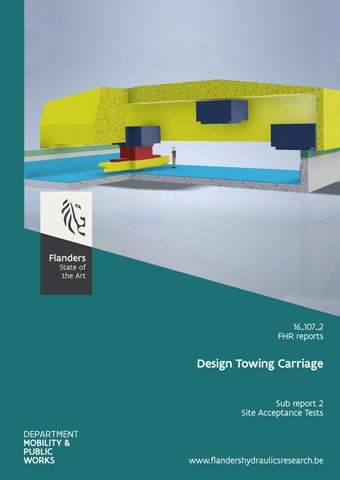
Cover figure © The Government of Flanders, Department of Mobility and Public Works, Flanders Hydraulics Research Legal notice Flanders Hydraulics Research is of the opinion that the information and positions in this report are substantiated by the available data and knowledge at the time of writing. The positions taken in this report are those of Flanders Hydraulics Research and do not reflect necessarily the opinion of the Government of Flanders or any of its institutions. Flanders Hydraulics Research nor any person or company acting on behalf of Flanders Hydraulics Research is responsible for any loss or damage arising from the use of the information in this report. Copyright and citation © The Government of Flanders, Department of Mobility and Public Works, Flanders Hydraulics Research 2020 D/2020/3241/51 This publication should be cited as follows: Delefortrie, G.; Geerts, S.; Lataire, E.; Mostaert, F. (2020). Design Towing Carriage: Sub report 2 – Site Acceptance Tests. Version 2.0. FHR Reports, 16_107_2. Flanders Hydraulics Research: Antwerp. Reproduction of and reference to this publication is authorised provided the source is acknowledged correctly. Document identification Customer: Keywords (3-5): Text (p.): Confidentiality:
Flanders Hydraulics Research Ref.: WL2020R16_107_2 Towing carriage, test program, acceptance 22 Appendices (p.): / ܈No ܈Available online
Author(s):
Delefortrie, G.; Geerts, S.
Control Name Reviser(s):
Project leader:
Lataire, E. (Ghent University)
Geerts, S.
Signature
Evert Lataire (Authentication)
Digitaal ondertekend door Evert Lataire (Authentication) Datum: 2020.04.20 16:52:42 +02'00' Getekend door: Stefan Geerts (Signature) Getekend op: 2020-04-23 12:37:14 +01:00 Reden: Ik keur dit document goed
Approval Head of Division:
F-WL-PP10-2 Version 7 Valid as from 3/01/2017
Mostaert, F.
Getekend door: Frank Mostaert (Signature) Getekend op: 2020-04-21 08:13:40 +01:00 Reden: Ik keur dit document goed
Design Towing Carriage - Sub report 2 – Site Acceptance Tests
Abstract This report describes the details of the site acceptance tests for the delivery of a towing carriage at the towing tank in the Flanders Maritime Laboratory, Ostend, Belgium. Part of this report has been published in the tender for the carriage design EVFH_2019_04.
Safety > Risk Analysis > Scale Model Tests.
Final version
WL2020R16_107_2
III
F-WL-PP10-2 Version 7 Valid as from 3/01/2017
Design Towing Carriage - Sub report 2 – Site Acceptance Tests
Contents Abstract ............................................................................................................................................................ III Contents ............................................................................................................................................................ V List of tables...................................................................................................................................................... VI List of figures ................................................................................................................................................... VII 1
Introduction ............................................................................................................................................... 1
2
Kinematic and load design of the carriage ................................................................................................ 2
3
Design vessels ............................................................................................................................................ 5
4
5
6
7
3.1
Overview ............................................................................................................................................ 5
3.2
KVLCC2 ............................................................................................................................................... 5
3.3
KCS ..................................................................................................................................................... 6
Kinematic acceptance ................................................................................................................................ 7 4.1
Positioning ......................................................................................................................................... 7
4.2
Operation........................................................................................................................................... 7
4.2.1
Longitudinal carriage ................................................................................................................. 7
4.2.2
Lateral carriage .......................................................................................................................... 8
4.2.3
Yaw table ................................................................................................................................... 8
4.2.4
Roll table .................................................................................................................................... 9
4.2.5
Combination of longitudinal carriage, lateral carriage and yaw table ...................................... 9
4.2.6
Combination of all sub mechanisms ........................................................................................ 11
Dynamic acceptance ................................................................................................................................ 12 5.1
Longitudinal carriage ....................................................................................................................... 12
5.2
Lateral carriage ................................................................................................................................ 12
5.3
Yaw table ......................................................................................................................................... 13
5.4
Roll table .......................................................................................................................................... 13
5.5
Combination of longitudinal carriage, lateral carriage and yaw table ............................................ 13
Realistic operation ................................................................................................................................... 15 6.1
Straight line tests ............................................................................................................................. 15
6.2
Longitudinal acceleration tests........................................................................................................ 17
6.3
Harmonic sway tests........................................................................................................................ 17
6.4
Harmonic yaw tests ......................................................................................................................... 18
6.5
Harmonic roll tests .......................................................................................................................... 20
References ............................................................................................................................................... 22
Final version
WL2020R16_107_2
V
Design Towing Carriage - Sub report 2 – Site Acceptance Tests
List of tables Table 1 – Design kinematic conditions of the carriage during manual positioning. ......................................... 2 Table 2 – Design kinematic conditions of the carriage during test execution. ................................................. 2 Table 3 – Kinematic accuracy during tests. ....................................................................................................... 3 Table 4 – Design loads. ...................................................................................................................................... 4 Table 5 – Ship data of T80 at design draft ......................................................................................................... 5 Table 6 – Ship data of C80 at design draft ......................................................................................................... 6 Table 7 – Kinematic test runs for the longitudinal carriage .............................................................................. 7 Table 8 – Kinematic test runs for the lateral carriage ....................................................................................... 8 Table 9 – Kinematic test runs for the yaw table ................................................................................................ 9 Table 10 – Kinematic test runs for the roll table ............................................................................................... 9 Table 11 – Kinematic test runs for the combination of horizontal sub mechanisms ........................................ 9 Table 12 – Kinematic test run for the combination of all sub mechanisms .................................................... 11 Table 13 – Dynamic test run for the longitudinal carriage .............................................................................. 12 Table 14 – Dynamic test run for the lateral carriage ....................................................................................... 12 Table 15 – Dynamic test run for the yaw table ............................................................................................... 13 Table 16 – Dynamic test run for the yaw table ............................................................................................... 13 Table 17 – Dynamic test runs for the combination of horizontal sub mechanisms ........................................ 13 Table 18 – Dynamic test runs for the combination of horizontal sub mechanisms: expected load ............... 14 Table 19 – Straight line test parameters ......................................................................................................... 15 Table 20 – Longitudinal acceleration test parameters .................................................................................... 17 Table 21 – Harmonic sway test parameters .................................................................................................... 17 Table 22 – Harmonic yaw test parameters ..................................................................................................... 18 Table 23 – Harmonic roll test parameters ....................................................................................................... 20
VI
WL2020R16_107_2
Final version
Design Towing Carriage - Sub report 2 – Site Acceptance Tests
List of figures Figure 1 – Kinematic test runs for the longitudinal carriage ............................................................................. 8 Figure 2 – Kinematic test runs for the lateral carriage ...................................................................................... 8 Figure 3 – Kinematic test runs for the yaw table .............................................................................................. 8 Figure 4 – K_G001 – K_G006 : trajectory sketches ......................................................................................... 10 Figure 5 – Kinematic test run for the combination of all sub mechanisms ..................................................... 11
Final version
WL2020R16_107_2
VII
Design Towing Carriage - Sub report 2 – Site Acceptance Tests
1 Introduction This report describes the tests that will be carried out on site to approve the new towing carriage. These will be performed in the following order: 1. 2. 3. 4.
Visual check of the (main components of the) carriage and rails Verification of the functionality of the (manual) commands Verification of the functionality of the safety Documentation and plans, i.e.: a. User manual b. Maintenance schedule c. Main equipment data sheets d. Datasheet of spare parts e. Recommended spare parts list f. Certificate of compliance g. As built technical plans (electrical, hydraulic, mechanical, pneumatic,‌) h. Calibration certificates 5. Operator training 6. Test runs: a. Kinematic operation b. Dynamic operation c. Realistic operation
The present report provides more details on the test runs. The kinematic operation will check the functionality of the carriage exploring the limiting positions, velocities and accelerations. The dynamic operation will check the functionality of the carriage exploring the load limits. The realistic operation will check the behaviour in normal, realistic test runs.
Final version
WL2020R16_107_2
1
Design Towing Carriage - Sub report 2 – Site Acceptance Tests
2 Kinematic and load design of the carriage To set the ideas the tables mentioning the design kinematic and dynamic conditions of the carriage are mentioned here. However, the values written in the tender prevail. Heave and pitch steering are only relevant for a hexapod setup. See the tender for more information on the axis system. Table 1 – Design kinematic conditions of the carriage during manual positioning.
Velocities (if steered)
Accelerations (if steered)
Âą 1.000 m/s
¹ 0.400 m/s²
Âą 9.75 m (except harbour limitations)
Âą 1.000 m/s
¹ 0.400 m/s²
Heave
Between 0.25 m and 2.25 m above tank bottom
Âą 0.100 m/s
Âą 0.050 m/s
Roll
¹ 20°
¹ 5°/s
¹ 1°/s²
Pitch
¹ 6°
¹ 5°/s
¹ 1°/s²
Yaw
Between -365° and +365° (except harbour limitations)
¹ 5°/s
¹ 1°/s²
DOF
Position in tank
Surge Sway
Between -17 m and (XTMAX(1) - 2 đ?‘…đ?‘…đ?‘Śđ?‘Śđ?‘Śđ?‘Ś (2))
Table 2 – Design kinematic conditions of the carriage during test execution.
Velocities (if steered)
Accelerations (if steered)
Âą 3.000 m/s
¹ 0.400 m/s²
Âą 9.75 m
Âą 1.300 m/s
¹ 0.700 m/s²
Heave
Âą 0.20 m
Âą 0.700 m/s
¹ 0.700 m/s²
Roll
¹ 20°
¹ 16°/s
¹ 32°/s²
Pitch
¹ 6°
¹ 16°/s
¹ 16°/s²
Yaw
Between -365° and +365°
¹ 16°/s
¹ 8°/s²
DOF
Position in tank
Surge Sway
Between (XTMIN + 2 đ?‘…đ?‘…đ?‘Śđ?‘Śđ?‘Śđ?‘Ś ) and (XTMAX - 2 đ?‘…đ?‘…đ?‘Śđ?‘Śđ?‘Śđ?‘Ś )
The slip errors should be below: – SLPX = 0.01 m for the longitudinal carriage; – SLPY = 0.005 m for the lateral carriage; – SLPPSI = 0.100° for the yaw mechanism;
1 2
2
Physical tank boundary (wall) Yaw shaft radius WL2020R16_107_2
Final version
Design Towing Carriage - Sub report 2 – Site Acceptance Tests Table 3 – Kinematic accuracy during tests.
DOF
Surge
Resolution
0.1 mm
Acceleration accuracy (if steered)
Position accuracy
Velocity accuracy (if steered)
1.5 mm
The maximum of 0.5 mm/s and 0.50%
0.5 N error: (3)
The maximum of 0.5 mm/s and 0.50%
0.5 N error:
The maximum of 0.5 mm/s and 0.50%
0.025 mm/s²
1.3 mm Sway
0.1 mm
Position accuracy when performing a harmonic sway motion: 0.70% of the motion amplitude, but never larger than 10 mm.
Heave
0.05 mm
0.15 mm
0.025 mm/s²
2.5 N error: 0.050 mm/s²
0.03° Roll
0.01°
Position accuracy when performing a harmonic roll motion: 0.70% of the motion amplitude
The maximum of 0.08 °/s and 3.00%
0.1 Nm error:
The maximum of 0.08 °/s and 3.00%
0.5 Nm error:
The maximum of 0.08 °/s and 3.00%
0.5 Nm error:
0.08°/s²
0.03° Pitch
0.01°
Position accuracy when performing a harmonic pitch motion: 0.70% of the motion amplitude
0.03°/s²
0.03° Yaw
3
0.01°
Position accuracy when performing a harmonic yaw motion: 0.70% of the motion amplitude
0.03°/s²
Acceptable errors on a ship model with a displacement of 1 ton.
Final version
WL2020R16_107_2
3
Design Towing Carriage - Sub report 2 – Site Acceptance Tests Table 4 – Design loads.
Maximal load on ship model DOF
Maximal load on carriage
(Range of dynamometers) Captive mode
Free running mode
Captive mode
Surge
1.0 kN
6.4 kN
Sway
1.0 kN
8.0 kN
Heave
10.0 kN
Roll
1.0 kNm
≥10.0 kN(4)
Pitch
8.0 kNm
Yaw
8.0 kNm
p.m.
2.0 kNm
Free running mode
p.m.
≥8.0 kNm 16.0 kNm
A safety factor has to be agreed for ≤. The maximal weight of a ship model is for instance 65 kN. This load will apply when the towing tank is emptied involuntary. In such case a safety mechanism must be implemented, in this example the ship model could be lowered.
4
4
WL2020R16_107_2
Final version
Design Towing Carriage - Sub report 2 – Site Acceptance Tests
3 Design vessels 3.1 Overview The dynamic and realistic tests will be carried out with two public domain vessels, which are widely used in manoeuvring and towing tanks over the world, namely the KVLCC2(5) and the KCS(6). The forces acting on these vessels while manoeuvring are sufficiently known. FHR will have the ship models ready as described in the following paragraphs.
3.2 KVLCC2 The dynamic load of the carriage will be checked with a 1/40 scale model of the KVLCC2 (T80). Table 5 – Ship data of T80 at design draft (even keel)
KVLCC2 (T80) – single propeller – single rudder 8.125 #propeller blades 4 đ??żđ??żđ?‘‚đ?‘‚đ?‘‚đ?‘‚ (m) 8.000 0.2465 đ??żđ??żđ?‘ƒđ?‘ƒđ?‘ƒđ?‘ƒ (m) đ??ˇđ??ˇđ?‘ƒđ?‘ƒ (m) đ?‘ƒđ?‘ƒďż˝ (-) 1.450 0.721 đ??ľđ??ľ (m) đ??ˇđ??ˇ 0.520 0.431 đ?‘‡đ?‘‡ (m) đ??´đ??´đ??´đ??´đ??´đ??´ (-) 0.810 0.0698 đ??śđ??śđ??ľđ??ľ (-) đ??´đ??´đ?‘…đ?‘… (m²) 4890 Model scale 1:40 đ?‘šđ?‘š (kg) ����� ����� 0.6073 9.9625 đ??žđ??žđ??žđ??žđ?‘‡đ?‘‡ (m) đ??žđ??žđ??žđ??žđ??żđ??ż (m)
The ship model will be ballasted at full draft, with the following expected inertia, referred to the ship bound axis system (origin amidships on the water plane): 0.280 Âą 0.008 ďż˝đ?‘Žđ?‘Ž = ďż˝ 0 ďż˝ đ?‘šđ?‘š; đ?’™đ?’™ Âą0.01 1000 Âą 250 0 đ?‘šđ?‘šđ?‘šđ?‘šđ?‘šđ?‘šđ?‘šđ?‘šđ?‘šđ?‘šđ?‘šđ?‘šđ?‘šđ?‘šđ?‘šđ?‘šđ?‘šđ?‘š đ?‘°đ?‘°ďż˝ = ďż˝ ďż˝ đ?‘˜đ?‘˜đ?‘˜đ?‘˜đ?‘˜đ?‘˜Â˛ 0 19000 Âą 500 0 đ?‘šđ?‘šđ?‘–đ?‘–đ?‘–đ?‘–đ?‘–đ?‘–đ?‘–đ?‘–đ?‘–đ?‘–đ?‘–đ?‘–đ?‘–đ?‘–đ?‘–đ?‘– 0 19000 Âą 500
The water depth will be 1000 mm.
đ??ľđ??ľđ??ľđ??ľ
The maximum sailing speed is determined based on the blockage đ?‘šđ?‘š = = â„Žđ?‘Šđ?‘Š Froude number is: đ??šđ??šđ??šđ??šâ„Ž,đ?‘?đ?‘?đ?‘?đ?‘?đ?‘?đ?‘?đ?‘?đ?‘?1
đ?‘Žđ?‘Žđ?‘Žđ?‘Žđ?‘Žđ?‘Žđ?‘Žđ?‘Žđ?‘Žđ?‘Žđ?‘Žđ?‘Ž(1 − đ?‘šđ?‘š) = ďż˝2đ?‘ đ?‘ đ?‘ đ?‘ đ?‘ đ?‘ ďż˝ �� 3
3ďż˝ 2
1.45∙0.52 1∙20
= 0.0377. The critical
= 0.7657
The critical speed is then 2.398 m/s. The maximum test speed is 84% of that speed or 2.015 m/s. This value is rounded to 2 m/s as maximum speed for the load test. The ship model will be rigidly connected to the carriage (without dynamometers), but remains free to heave and pitch in the 4 DOF setup.
5 6
http://www.simman2019.kr/contents/KVLCC2.php http://www.simman2019.kr/contents/KCS.php
Final version
WL2020R16_107_2
5
Design Towing Carriage - Sub report 2 – Site Acceptance Tests
3.3 KCS The realistic operation of the carriage will be checked with a 1/29 scale model of the KCS (C80). Table 6 – Ship data of C80 at design draft (even keel)
KCS (C80) – single propeller – single rudder 8.017 #propeller blades đ??żđ??żđ?‘‚đ?‘‚đ?‘‚đ?‘‚ (m) 7.931 đ??żđ??żđ?‘ƒđ?‘ƒđ?‘ƒđ?‘ƒ (m) đ??ˇđ??ˇđ?‘ƒđ?‘ƒ (m) đ?‘ƒđ?‘ƒďż˝ (-) 1.110 đ??ľđ??ľ (m) đ??ˇđ??ˇ 0.3724 đ?‘‡đ?‘‡ (m) đ??´đ??´đ??´đ??´đ??´đ??´ (-) 0.651 đ??śđ??śđ??ľđ??ľ (-) đ??´đ??´đ?‘…đ?‘… (m²) 2134 Model scale đ?‘šđ?‘š (kg) ����� ����� 0.5154 đ??žđ??žđ??žđ??žđ?‘‡đ?‘‡ (m) đ??žđ??žđ??žđ??žđ??żđ??ż (m)
4 0.2724 1.000 0.700 0.0646 1:29 13.333
The ship model will be ballasted at full draft, with the following expected inertia, referred to the ship bound axis system (origin amidships on the water plane): −0.118 Âą 0.008 0 ďż˝ đ?‘šđ?‘š; −0.05 Âą 0.01 0 minimized ďż˝ đ?‘˜đ?‘˜đ?‘˜đ?‘˜đ?‘˜đ?‘˜Â˛ 8400 Âą 250 0 0 8400 Âą 250
��� = � ��
300 Âą 50 đ?‘°đ?‘°ďż˝ = ďż˝ 0 minimized
The water depth will be 986.9 mm (165% ukc).
đ??ľđ??ľđ??ľđ??ľ
The maximum sailing speed is determined based on the blockage đ?‘šđ?‘š = = â„Žđ?‘Šđ?‘Š critical Froude number is: đ??šđ??šđ??šđ??šâ„Ž,đ?‘?đ?‘?đ?‘?đ?‘?đ?‘–đ?‘–đ?‘Ąđ?‘Ą1
arcsin(1 − đ?‘šđ?‘š) = ďż˝2sin ďż˝ �� 3
3ďż˝ 2
1.11∙0.3724 0.9869∙20
= 0.0209. The
= 0.8247
The critical speed is then 2.5829 m/s. The maximum test speed is 84% of that speed or 2.1696 m/s. During the realistic test program the maximum speed will be 1.624 m/s (75% of the critical speed). The ship model will be connected to the carriage with dynamometers and remains free to heave and pitch in the 4 DOF setup.
6
WL2020R16_107_2
Final version
Design Towing Carriage - Sub report 2 – Site Acceptance Tests
4 Kinematic acceptance The kinematic acceptance is performed without ship model attached to the carriage and in a dry tank.
4.1 Positioning In manual mode the carriage elements will be subsequently and independently positioned to their maximal values mentioned in Table 1.
4.2 Operation The tests described in the following paragraph will be carried out and the results will be checked with Table 3. 4.2.1
Longitudinal carriage
Only the longitudinal carriage is moved, the lateral carriage, yawing and rolling tables are positioned at their origin. The acceleration �� to steady speed �� is performed during a time �� as follows (��: 0 → ��): ��(��) =
The acceleration (= deceleration) distance is đ?‘‘đ?‘‘ = starting at one of the mentioned positions.
6đ?‘˘đ?‘˘đ?‘˘đ?‘˘ [đ?‘‡đ?‘‡ − đ?‘Ąđ?‘Ą] đ?‘‡đ?‘‡ 3
���� 2
. The five tests mentioned in Table 7 will be performed
Table 7 – Kinematic test runs for the longitudinal carriage
Test run
Steady distance (m)
Start position (m)
0.05
đ?‘‘đ?‘‘ (m)
Steering interval (ms)
K_C001
�� (m/s)
0.0375
250
130
0 OR 134
K_C101
0.25
0.1250
125
130
0 OR 134
K_C501
0.75
1.0594
25
130
0 OR 134
K_CA01
1.50
4.2188
25
125
0 OR 134
K_CB01
3.00
16.8750
25
100
0 OR 134
Final version
WL2020R16_107_2
7
Design Towing Carriage - Sub report 2 – Site Acceptance Tests Figure 1 – Kinematic test runs for the longitudinal carriage: trajectory sketch
4.2.2
Lateral carriage
Only the lateral carriage is moved. The longitudinal carriage is positioned at 70 m, the yawing and rolling tables are positioned at their origin. The two tests mentioned in Table 8 will be performed starting at one of the mentioned positions. The acceleration is performed using the same methodology as for the longitudinal carriage, but this time the acceleration times are given. Table 8 – Kinematic test runs for the lateral carriage
Test run
Steady time (s)
Start position (m)
0.65
�� (s)
Steering interval (ms)
K_M001
đ?‘Łđ?‘Ł (m/s)
1.400
25
25
-8.58 OR +8.58
K_M101
1.30
2.800
25
8.5
-7.345 OR +7.345
Figure 2 – Kinematic test runs for the lateral carriage: trajectory sketch
4.2.3
Yaw table
Only the yaw table is moved. The longitudinal carriage is positioned at 70 m, the lateral carriage and rolling table are positioned at their origin. The five tests mentioned in Table 9 will be performed starting at one of the mentioned positions. The acceleration is performed using the same methodology as for the longitudinal and lateral carriages. Figure 3 – Kinematic test runs for the yaw table: trajectory sketch
8
WL2020R16_107_2
Final version
Design Towing Carriage - Sub report 2 – Site Acceptance Tests Table 9 – Kinematic test runs for the yaw table
4.2.4
Test run
r (°/s)
Steering interval (ms)
Steady time (s)
Start position (°)
0.32
�� (s)
K_M201
0.6
100
2249
-359.84 OR +359.84
K_M301
2.18
0.425
25
329
-358.61 OR +358.61
K_M401
4.00
0.750
25
168
-337.50 OR +337.50
K_M501
8.00
1.500
25
84
-342.00 OR +342.00
K_M601
16.00
3.000
25
42
-360.00 OR +360.00
Roll table
Only the roll table is moved. The longitudinal carriage is positioned at 70 m, the lateral carriage and yawing table are positioned at their origin. The test mentioned in Table 10 will be performed in one of the mentioned directions. A harmonic roll motion is imposed. The initial acceleration is performed using a similar methodology as for the other sub carriages and takes one roll period. The steady state conditions lasts for 20 s. The start angle is always 0°. Table 10 – Kinematic test runs for the roll table
Test run K_M201 4.2.5
đ?œ‘đ?œ‘đ??´đ??´ (°) 8
đ?‘‡đ?‘‡ (s) đ?œ‹đ?œ‹
Steering interval (ms)
Roll period (s)
Start direction (°)
100
đ?œ‹đ?œ‹
+/-
Combination of longitudinal carriage, lateral carriage and yaw table
These combinations are tested with the execution of harmonic yaw tests, during which the roll table is fixed at its origin. The initial acceleration and the deceleration phase take half a period of the harmonic motion. The steering interval is always 25 ms. The tests start at x = 0 m for the positive direction and x = 130 m for the negative direction. Each test of Table 11 will be carried out in one of these directions. The test velocities are expressed in the ship bound axis system (of the virtual ship). Table 11 – Kinematic test runs for the combination of horizontal sub mechanisms
Test run
u (m/s)
Period (s)
K_G001
đ?œ“đ?œ“đ??´đ??´ (°)
2.3
đ?‘&#x;đ?‘&#x;̇đ?‘€đ?‘€đ?‘€đ?‘€đ?‘€đ?‘€ (°/s²)
Start direction (°)
86.00
đ?‘&#x;đ?‘&#x;đ?‘€đ?‘€đ?‘€đ?‘€đ?‘€đ?‘€ (°/s)
32
0.50
0.2
+/-
K_G101
32
1.00
43.00
4.7
0.7
+/-
K_G201
32
1.50
28.67
7.0
1.5
+/-
K_G301
32
1.75
12.57 (4đ?œ‹đ?œ‹)
16.0
8.0
+/-
K_G401
32
2.00
21.50
9.4
2.7
+/-
K_G501
31
2.50
18.1
10.8
3.7
+/-
K_G601
25
3.00
21.7
7.2
2.1
+/-
Final version
WL2020R16_107_2
9
Design Towing Carriage - Sub report 2 – Site Acceptance Tests Figure 4 – K_G001 – K_G006 : trajectory sketches
10
WL2020R16_107_2
Final version
Design Towing Carriage - Sub report 2 – Site Acceptance Tests
4.2.6
Combination of all sub mechanisms
The combination of all sub mechanisms will be tested with the parameters mentioned in Table 12. This test is a combination of a harmonic longitudinal speed, harmonic roll motion and harmonic yaw motion. All are expressed in the ship bound axis system (of the virtual ship). The steering interval is 25 ms. The initial positions of the sub carriages are: • • • •
x = 40.000 m; y = -3.492 m; φ = 0.00°; Ďˆ = -40.89°. Table 12 – Kinematic test run for the combination of all sub mechanisms
Test run K_MV01
đ?‘˘đ?‘˘đ??´đ??´ (m/s) 2.00
���� (s) 60
đ?œ‘đ?œ‘đ?‘˘đ?‘˘ (°) 0
đ?‘?đ?‘?đ??´đ??´ (°/s) 4
đ?‘‡đ?‘‡đ?‘?đ?‘? (s) 10
đ?œ‘đ?œ‘đ?‘?đ?‘? (°) 45
đ?‘&#x;đ?‘&#x;đ??´đ??´ (°/s) 7
đ?‘‡đ?‘‡đ?‘&#x;đ?‘&#x; (s) 30
đ?œ‘đ?œ‘đ?‘&#x;đ?‘&#x; (°) 135
Figure 5 – Kinematic test run for the combination of all sub mechanisms: trajectory sketch (top view only)
Final version
WL2020R16_107_2
11
Design Towing Carriage - Sub report 2 – Site Acceptance Tests
5 Dynamic acceptance All tests have to be carried out with the loaded scale model of the KVLCC2, as mentioned in 3.2. There are no dynamometers connected to the ship model. The loads are predicted bases on a manoeuvring model determined with scale model tests in the present towing tank (Delefortrie et al., 2016). As these predictions are extrapolations, the predicted loads are kept significantly below the design loads.
5.1 Longitudinal carriage During the longitudinal tests the following force acts on the ship model: 1 đ?‘‹đ?‘‹ = (đ?‘‹đ?‘‹đ?‘˘đ?‘˘Ě‡ − đ?‘šđ?‘š)đ?‘˘đ?‘˘Ě‡ + đ?œŒđ?œŒđ?œŒđ?œŒđ?œŒđ?œŒđ?‘˘đ?‘˘2 đ?‘‹đ?‘‹ ′(đ?›˝đ?›˝=0°) 2
1
For the design ship KVLCC2, the following values are used: (đ?‘‹đ?‘‹đ?‘˘đ?‘˘Ě‡ − đ?‘šđ?‘š) = -6100 kg and đ?œŒđ?œŒđ?œŒđ?œŒđ?œŒđ?œŒđ?‘‹đ?‘‹ ′(đ?›˝đ?›˝=0°) = -520 2 kg/m. The maximal design load is 6400 N. The test shown in Table 13 will be carried out at maximal acceleration at one of the shown start positions. The expected load is below 50% of the design load. Table 13 – Dynamic test run for the longitudinal carriage
Absolute force (N)
Test run
�� (m/s)
At maximal acceleration
At maximal speed
T8001A01_CC01
2.00
2960
2080
Start position (m) 0 OR 134
5.2 Lateral carriage During the lateral tests the following main force acts on the ship model: 1 đ?‘Œđ?‘Œ = (đ?‘Œđ?‘Œđ?‘Łđ?‘ŁĚ‡ − đ?‘šđ?‘š)đ?‘Łđ?‘ŁĚ‡ + đ?œŒđ?œŒđ?œŒđ?œŒđ?œŒđ?œŒđ?‘Łđ?‘Ł 2 đ?‘Œđ?‘Œ ′(đ?›˝đ?›˝=Âą90°) 2
1
For the design ship KVLCC2, the following values are used: (đ?‘Œđ?‘Œđ?‘Łđ?‘ŁĚ‡ − đ?‘šđ?‘š) = -12500 kg and đ?œŒđ?œŒđ?œŒđ?œŒđ?œŒđ?œŒđ?‘Œđ?‘Œ ′(đ?›˝đ?›˝=Âą90°) = 2 4000 kg/m. The maximal design load is 8000 N. The applied maximal acceleration is 0.35 m/s², in this way the expected load is below 60% of the design load. Table 14 – Dynamic test run for the lateral carriage
Test run T8001A01_M001
12
Absolute force (N)
đ?‘Łđ?‘Ł (m/s)
At maximal acceleration
At maximal speed
0.65
4800
1700
WL2020R16_107_2
Start position (m) -8.58 OR +8.58
Final version
Design Towing Carriage - Sub report 2 – Site Acceptance Tests
5.3 Yaw table During the yaw test the following main moment acts on the ship model: 2 1 1 đ?‘ đ?‘ = (đ?‘ đ?‘ đ?‘&#x;đ?‘&#x;̇ − đ??źđ??źđ?‘§đ?‘§đ?‘§đ?‘§ )đ?‘&#x;đ?‘&#x;̇ + đ?œŒđ?œŒđ??żđ??ż2 đ?‘‡đ?‘‡ ďż˝ đ?‘&#x;đ?‘&#x;đ?‘&#x;đ?‘&#x;ďż˝ đ?‘ đ?‘ ′(đ?›žđ?›ž=Âą90°) 2 2
1
For the design ship KVLCC2, the following values are used: (đ?‘ đ?‘ đ?‘&#x;đ?‘&#x;̇ − đ??źđ??źđ?‘§đ?‘§đ?‘§đ?‘§ ) = -40000 kgm² and đ?œŒđ?œŒđ??żđ??ż2 đ?‘‡đ?‘‡đ?‘ đ?‘ ′(đ?›žđ?›ž=Âą90°) 2 = -4000 kg. The maximal design load is 16000 Nm. The expected load is below 50% of the design load. Table 15 – Dynamic test run for the yaw table
Test run
r (°/s)
T8001A01_M601
16.00
Absolute moment (Nm) At maximal acceleration
At maximal speed
6800
5000
Start position (°) -360.00 OR +360.00
5.4 Roll table During the roll test the following main moment acts on the ship model: �����đ?‘‡đ?‘‡ đ?œ‘đ?œ‘ đ??žđ??ž = ďż˝đ??žđ??žđ?‘?đ?‘?̇ − đ??źđ??źđ?‘Ľđ?‘Ľđ?‘Ľđ?‘Ľ ďż˝đ?‘?đ?‘?̇ + đ??žđ??žđ?‘?đ?‘? đ?‘?đ?‘? − ∆đ??şđ??şđ??şđ??ş
For the design ship KVLCC2, the following values are used: ďż˝đ??žđ??žđ?‘?đ?‘?̇ − đ??źđ??źđ?‘Ľđ?‘Ľđ?‘Ľđ?‘Ľ ďż˝= -1500 kgm² andđ??žđ??žđ?‘?đ?‘? = -160 kgm². The maximal design load is 2000 Nm. The expected load is below 50% of the design load. Table 16 – Dynamic test run for the yaw table
Absolute moment (Nm) Test run
đ?œ‘đ?œ‘đ??´đ??´ (°)
Roll period (s)
T8001A01_M201
5
đ?œ‹đ?œ‹
At maximal speed
At maximal acceleration
30
900
Start direction (°) +/-
5.5 Combination of longitudinal carriage, lateral carriage and yaw table Table 17 gives an overview of the two harmonic yaw tests that will be carried out. Table 17 – Dynamic test runs for the combination of horizontal sub mechanisms
Test run T8001A01_G301 T8001A01_G401
Final version
đ?œ“đ?œ“đ??´đ??´ (°)
u (m/s)
Period (s)
32
1.75
12.57 (4đ?œ‹đ?œ‹)
32
2.00
21.50
đ?‘&#x;đ?‘&#x;đ?‘€đ?‘€đ?‘€đ?‘€đ?‘€đ?‘€ (°/s)
đ?‘&#x;đ?‘&#x;̇đ?‘€đ?‘€đ?‘€đ?‘€đ?‘€đ?‘€ (°/s²)
16.0
8.0
9.4
2.7
WL2020R16_107_2
�������� (°)
Start direction (°)
18.1
+/-
16.7
+/-
13
Design Towing Carriage - Sub report 2 – Site Acceptance Tests
The governing forces and moments during these tests are: đ?‘‹đ?‘‹ =
2 1 1 1 đ?œŒđ?œŒđ?œŒđ?œŒđ?œŒđ?œŒđ?‘˘đ?‘˘2 đ?‘‹đ?‘‹ ′(đ?›˝đ?›˝=0°) + đ?œŒđ?œŒđ?œŒđ?œŒđ?œŒđ?œŒ ďż˝đ?‘˘đ?‘˘2 + ďż˝ đ?‘&#x;đ?‘&#x;đ?‘&#x;đ?‘&#x;ďż˝ ďż˝ đ?‘‹đ?‘‹ ′(đ?›žđ?›ž) 2 2 2
2 1 1 đ?‘Œđ?‘Œ = (đ?‘Œđ?‘Œđ?‘&#x;đ?‘&#x;̇ − đ?‘šđ?‘šđ?‘Ľđ?‘Ľđ??şđ??ş )đ?‘&#x;đ?‘&#x;̇ + đ?œŒđ?œŒđ?œŒđ?œŒđ?œŒđ?œŒ ďż˝đ?‘˘đ?‘˘2 + ďż˝ đ?‘&#x;đ?‘&#x;đ?‘&#x;đ?‘&#x;ďż˝ ďż˝ đ?‘Œđ?‘Œ ′(đ?›žđ?›ž) 2 2
2 1 1 đ?‘ đ?‘ = (đ?‘ đ?‘ đ?‘&#x;đ?‘&#x;̇ − đ??źđ??źđ?‘§đ?‘§đ?‘§đ?‘§ )đ?‘&#x;đ?‘&#x;̇ + đ?œŒđ?œŒđ??żđ??ż2 đ?‘‡đ?‘‡ ďż˝đ?‘˘đ?‘˘2 + ďż˝ đ?‘&#x;đ?‘&#x;đ?‘&#x;đ?‘&#x;ďż˝ ďż˝ đ?‘ đ?‘ ′(đ?›žđ?›ž) 2 2
For the design ship KVLCC2, the following values are used: • • • • • •
1 2
đ?œŒđ?œŒđ?œŒđ?œŒđ?œŒđ?œŒđ?‘‹đ?‘‹ ′(đ?›˝đ?›˝=0°) = -520 kg/m;
đ?‘‹đ?‘‹ ′(đ?›žđ?›ž) = 0.006; đ?‘Œđ?‘Œđ?‘&#x;đ?‘&#x;̇ = -0.08 đ?‘šđ?‘šđ?‘šđ?‘š; đ?‘Œđ?‘Œ ′(đ?›žđ?›ž) = 0.03; (đ?‘ đ?‘ đ?‘&#x;đ?‘&#x;̇ − đ??źđ??źđ?‘§đ?‘§đ?‘§đ?‘§ ) = -40000 kgm²; đ?‘ đ?‘ ′(đ?›žđ?›ž) = 0.035.
The maximal predicted loads are (see Table 18): • • •
36% of the design load for the longitudinal direction; 17% of the design load for the lateral direction; 76% of the design load for the yawing table. Table 18 – Dynamic test runs for the combination of horizontal sub mechanisms: expected load (absolute values)
Test run
14
X (N)
Y (N)
N (Nm)
T8001A01_G301
��(��)
1593
đ?‘“đ?‘“(đ?‘˘đ?‘˘, đ?‘&#x;đ?‘&#x;) 232
đ?‘“đ?‘“(đ?‘&#x;đ?‘&#x;̇ ) 628
đ?‘“đ?‘“(đ?‘˘đ?‘˘, đ?‘&#x;đ?‘&#x;) 1160
đ?‘“đ?‘“(đ?‘&#x;đ?‘&#x;̇ )
5585
đ?‘“đ?‘“(đ?‘˘đ?‘˘, đ?‘&#x;đ?‘&#x;)
T8001A01_G401
2080
245
212
1225
1885
1486
WL2020R16_107_2
10820
Final version
Design Towing Carriage - Sub report 2 – Site Acceptance Tests
6 Realistic operation All tests have to be carried out with the loaded scale model of the KCS, as mentioned in 3.2. The ship is connected with dynamometers to the carriage. Accelerations are significantly below the carriage capabilities.
6.1 Straight line tests Four tests selected from Table 19 will be carried out. Tests at positive velocity start at x = 0 m. Tests at negative velocity start at x = 130 m. The lateral carriage is always at zero position. Table 19 – Straight line test parameters
Test run
Longitudinal carriage velocity (m/s)
Yaw table position (°)
Roll table position (°)
C8001A01_CB10
0.1911
0
0
C8001A01_CB11
0.1911
2.5
0
C8001A01_CB12
0.1911
5
0
C8001A01_CB13
0.1911
10
0
C8001A01_CB14
0.1911
25
0
C8001A01_CB15
0.1911
40
0
C8001A01_CB16
0.1911
55
0
C8001A01_CB17
0.1911
70
0
C8001A01_CB18
0.1911
90
0
C8001A01_CBP0
0.1911
0
2.5
C8001A01_CBP1
0.1911
0
5
C8001A01_CBP2
0.1911
0
-2.5
C8001A01_CBP3
0.1911
0
-5
C8001A01_CBP4
0.1911
5
5
C8001A01_CBP5
0.1911
5
-5
C8001A01_CBP6
0.1911
-5
5
C8001A01_CBP7
0.1911
-5
-5
Final version
WL2020R16_107_2
15
Design Towing Carriage - Sub report 2 – Site Acceptance Tests
Test run
Longitudinal carriage velocity (m/s)
Yaw table position (°)
Roll table position (°)
C8001A01_CC00
0.3344
0
0
C8001A01_CC11
0.3344
5
0
C8001A01_CC12
0.3344
10
0
C8001A01_CC13
0.3344
-5
0
C8001A01_CC14
0.3344
-10
0
C8001A01_CE00
0.6687
0
0
C8001A01_CE11
0.6687
5
0
C8001A01_CE12
0.6687
10
0
C8001A01_CF00
0.8359
0
0
C8001A01_CFP0
0.8359
0
2.5
C8001A01_CFP1
0.8359
0
-2.5
C8001A01_CI00
1.6240
0
0
C8001A01_CY00
-0.1911
0
0
C8001A01_CYP0
-0.1911
0
2.5
C8001A01_CYP1
-0.1911
0
-2.5
C8001A01_CY23
-0.1911
10
0
C8001A01_CY26
-0.1911
25
0
C8001A01_CY29
-0.1911
-10
0
C8001A01_CY32
-0.1911
-25
0
C8001A01_CZ00
-0.4776
0
0
C8001A01_CZP0
-0.4776
0
2.5
C8001A01_CZP1
-0.4776
0
-2.5
C8001A01_CZ23
-0.4776
10
0
C8001A01_CZ26
-0.4776
25
0
C8001A01_CZ29
-0.4776
-10
0
C8001A01_CZ32
-0.4776
-25
0
16
WL2020R16_107_2
Final version
Design Towing Carriage - Sub report 2 – Site Acceptance Tests
6.2 Longitudinal acceleration tests The two tests selected from Table 20 will be carried out. Tests at positive velocity start at x = 0 m. Tests at negative velocity start at x = 130 m. The lateral carriage, yaw table and roll table are always at zero position. Table 20 – Longitudinal acceleration test parameters
Test run
Average carriage velocity (m/s)
Amplitude of carriage velocity (m)
Period of harmonic motion (s)
C8001A01_ML00
-0.1911
-0.1911
100
C8001A01_MN01
0.4776
0.4776
100
6.3 Harmonic sway tests Four tests selected from Table 21 will be carried out. Tests at positive velocity start at x = 0 m. Tests at negative velocity start at x = 130 m. The yaw and roll table are always at zero position. Table 21 – Harmonic sway test parameters
Test run
Longitudinal carriage velocity (m/s)
Amplitude of lateral carriage (m)
Period of harmonic motion (s)
C8001A01_FB00
0.1911
0.3
50
C8001A01_FB01
0.1911
0.3
80
C8001A01_FB02
0.1911
0.3
105
C8001A01_FB03
0.1911
0.3
130
C8001A01_FD00
0.4776
0.3
36
C8001A01_FD01
0.4776
0.3
80
C8001A01_FE00
0.6687
0.3
32
C8001A01_FY00
-0.1911
0.3
130
C8001A01_FY01
-0.1911
0.3
90
Final version
WL2020R16_107_2
17
Design Towing Carriage - Sub report 2 – Site Acceptance Tests
6.4 Harmonic yaw tests Four tests selected from Table 22 will be carried out. Tests at positive velocity start at x = 0 m. Tests at negative velocity start at x = 130 m. The roll table is always at zero position. The lateral carriage is moved in such way to enable the harmonic yaw motion Table 22 – Harmonic yaw test parameters
Test run
Longitudinal ship speed (m/s)
Average position of yaw table (°)
Amplitude of yaw table (°)
Period of harmonic motion (s)
C8001A01_GA00
0.09555
70
5
135
C8001A01_GB00
0.1911
0
15
67
C8001A01_GB01
0.1911
0
25
67
C8001A01_GB02
0.1911
0
35
67
C8001A01_GB03
0.1911
5
25
67
C8001A01_GB04
0.1911
-5
25
67
C8001A01_GB05
0.1911
10
25
67
C8001A01_GB06
0.1911
-10
25
67
C8001A01_GB07
0.1911
0
15
46
C8001A01_GB08
0.1911
0
25
46
C8001A01_GB09
0.1911
0
35
46
C8001A01_GB20
0.1911
0
10
67
C8001A01_GB21
0.1911
25
10
67
C8001A01_GB22
0.1911
-25
10
67
C8001A01_GD00
0.4776
0
5
34
C8001A01_GD01
0.4776
0
10
34
C8001A01_GD02
0.4776
0
15
34
C8001A01_GD03
0.4776
5
10
34
C8001A01_GD04
0.4776
-5
10
34
C8001A01_GD05
0.4776
10
10
34
18
WL2020R16_107_2
Final version
Design Towing Carriage - Sub report 2 – Site Acceptance Tests
Test run
Longitudinal ship speed (m/s)
Average position of yaw table (°)
Amplitude of yaw table (°)
Period of harmonic motion (s)
C8001A01_GD06
0.4776
-10
10
34
C8001A01_GD07
0.4776
0
5
23
C8001A01_GD08
0.4776
0
10
23
C8001A01_GD09
0.4776
0
15
23
C8001A01_GF00
0.8359
0
5
20
C8001A01_GF01
0.8359
0
10
20
C8001A01_GF02
0.8359
0
15
20
C8001A01_GF03
0.8359
5
10
20
C8001A01_GF04
0.8359
-5
10
20
C8001A01_GG00
1.1464
0
5
15
C8001A01_GG01
1.1464
0
10
15
C8001A01_GG02
1.1464
0
15
15
C8001A01_GZ00
-0.4776
0
15
46
C8001A01_GZ01
-0.4776
0
25
46
C8001A01_GZ02
-0.4776
0
35
46
C8001A01_GZ03
-0.4776
2.5
25
46
C8001A01_GZ04
-0.4776
-2.5
25
46
C8001A01_GZ05
-0.4776
5
25
46
C8001A01_GZ06
-0.4776
-5
25
46
C8001A01_GZ07
-0.4776
10
25
46
C8001A01_GZ08
-0.4776
-10
25
46
C8001A01_GZ30
-0.4776
0
5
46
Final version
WL2020R16_107_2
19
Design Towing Carriage - Sub report 2 – Site Acceptance Tests
6.5 Harmonic roll tests Four tests selected from Table 23 will be carried out. Tests at positive velocity start at x = 0 m. Tests at negative velocity start at x = 130 m. Tests at zero velocity are at x = 70 m. Table 23 – Harmonic roll test parameters
Amplitude of roll table (°)
Period of harmonic motion (s)
90
5
14
0
90
5
7
C8001A01_MAP2
0
90
4
3
C8001A01_MBP0
0.1911
0
5
600
C8001A01_MBP1
0.1911
5
5
600
C8001A01_MBP2
0.1911
10
5
600
C8001A01_MBP3
0.1911
25
5
600
C8001A01_MBP4
0.1911
40
5
600
C8001A01_MBP5
0.1911
55
5
600
C8001A01_MBP6
0.1911
70
5
600
C8001A01_MBP7
0.1911
90
5
600
C8001A01_MBP8
0.1911
-5
5
600
C8001A01_MBP9
0.1911
-10
5
600
C8001A01_MBPA
0.1911
-25
5
600
C8001A01_MBPB
0.1911
-40
5
600
C8001A01_MBPC
0.1911
-55
5
600
C8001A01_MBPD
0.1911
-70
5
600
C8001A01_MBPE
0.1911
-90
5
600
C8001A01_MCP0
0.3344
0
5
14
C8001A01_MCP1
0.3344
0
5
7
C8001A01_MCP2
0.3344
0
4
3
Test run
Longitudinal ship speed (m/s)
C8001A01_MAP0
0
C8001A01_MAP1
20
Position of yaw table (°)
WL2020R16_107_2
Final version
Design Towing Carriage - Sub report 2 – Site Acceptance Tests
Position of yaw table (°)
Amplitude of roll table (°)
Period of harmonic motion (s)
Test run
Longitudinal ship speed (m/s)
C8001A01_MEP0
0.6687
0
5
14
C8001A01_MEP1
0.6687
0
5
7
C8001A01_MEP2
0.6687
0
4
3
C8001A01_MGP0
1.1464
0
5
14
C8001A01_MGP1
1.1464
0
5
7
C8001A01_MGP2
1.1464
0
4
3
C8001A01_MYP0
-0.1911
0
5
14
C8001A01_MYP1
-0.1911
0
5
7
C8001A01_MYP2
-0.1911
0
4
3
C8001A01_MZP0
-0.4776
0
5
14
C8001A01_MZP1
-0.4776
0
5
7
C8001A01_MZP2
-0.4776
0
4
3
Final version
WL2020R16_107_2
21
Design Towing Carriage - Sub report 2 – Site Acceptance Tests
7 References Delefortrie, G.; Eloot, K.; Lataire, E.; Van Hoydonck, W.; Vantorre, M. (2016). Captive model tests based 6 DOF shallow water manoeuvring model, in: (2016). Proceedings of the 4th International Conference on Ship Manoeuvring in Shallow and Confined Water with Special Focus on Ship Bottom Interaction, Hamburg, Germany, 23 to 25 May 2016 (4th MASHCON). Bundesanstalt für Wasserbau. ISBN 978-3-939230-38-0. pp.273–286
22
WL2020R16_107_2
Final version
DEPARTMENT MOBILITY & PUBLIC WORKS Flanders hydraulics Research Berchemlei 115, 2140 Antwerp T +32 (0)3 224 60 35 F +32 (0)3 224 60 36 waterbouwkundiglabo@vlaanderen.be www.flandershydraulicsresearch.be