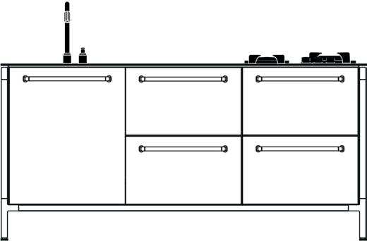
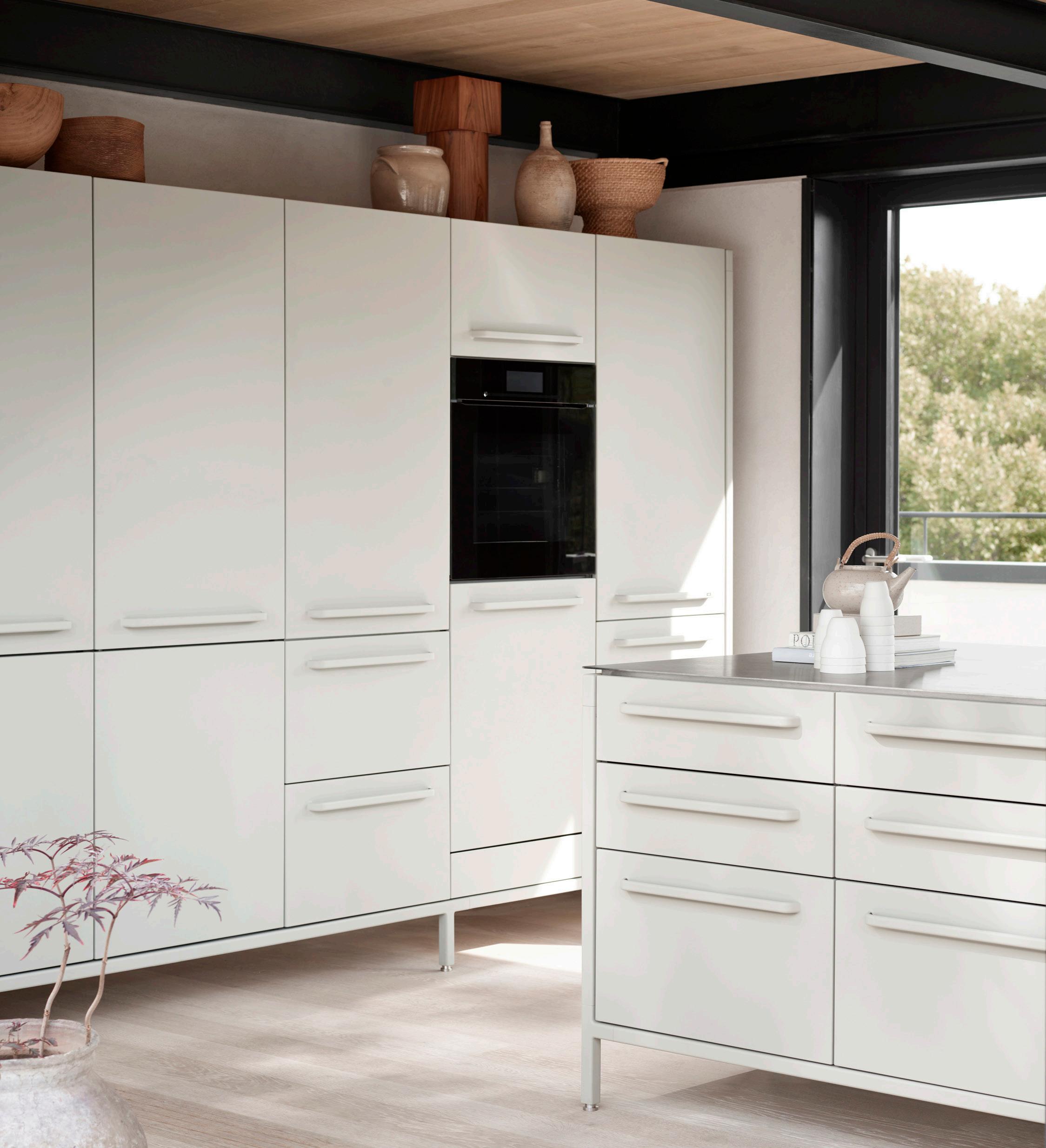
VIPP V1 Kitchen

1: Quickguide
1. Start VIPP app 2. Assemble frames - level
Tighten bottom profiles
Remove drawers and doors
5. Place cabinets on frame - connect them 6. F ix cabinets to bottom and side 7. Mount work top 8. Install appliances 9. Reinstall drawers and doors and align 10. Handover kitchen to client
2:Tools
Torque wrench 30nm (Frame)
Electric drill
Holesaw 54mm (Power outlet)
Screwdrivers Clamps Jigsaw
T8, T15, T20 T40
Flat head
Level
Philips / PZ2 5m
Measuring tape ≥5m Knife
Shims Black sanitary silicone (induction hob)
Ekstra 3,5mm metal drill bits (Island w/seating) 0,5
3: Kitchen installer
Read the installation manual Check appliance guide

Handle the kitchen and workspace with care
Contact Vipp if you have any questions or damaged items
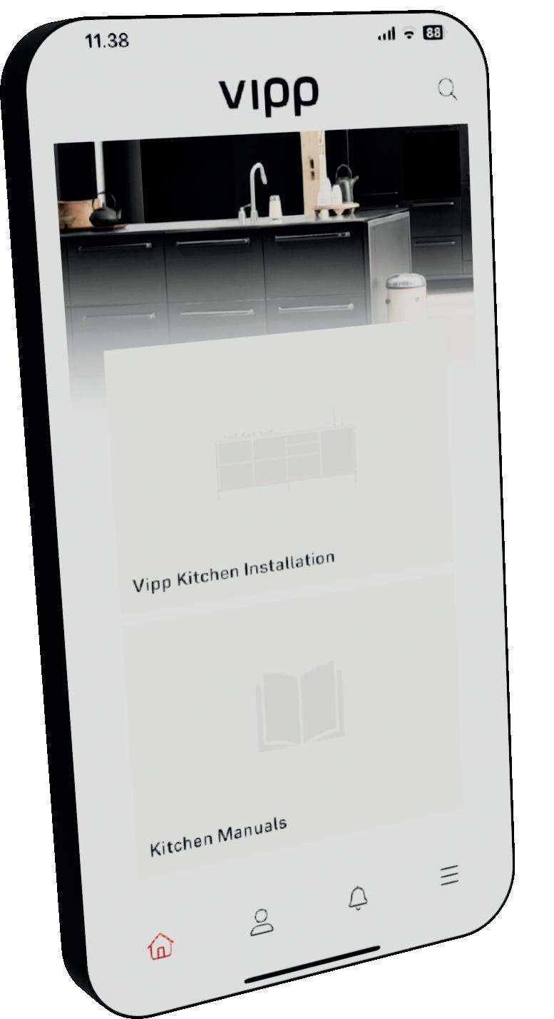
4: Vipp app
It is mandatory to upload pictures and information to the Vipp app throughout the installation. The app will guide you through the required steps. If questions arise during installation please reach out to Vipp.


5: Frame
Follow these steps carefully to ensure the kitchen’s overall strength. Start by finding the Kitchen configuration.
5.1: Dimension chart
Find the correct length for front- and suspension profiles.
5.2: Assembling the frame
5.2.1: Run the adjustable feet out
5.2.2: Attatch aluminum profiles
Run all adjustable feet out 5mm. This allows height adjustment both ways when leveling the frame at a later stage.
Attatch aluminum profiles with supplied machine screws. Screw holes facing inwards and downwards.
5.2.3: Middle leg
NOTE: Make sure to use the right length as some profiles are close to being same length. 5,0x25 5,0x25 5,0x25 Powers outlets towards wall 5mm
5.2.4: Fit the other side panel
Where the configuration dictates, support legs are fitted. Fit the other side panel.
5.2.5: Repeat steps 4.1.1-4.1.4 with all modules
5.2.6: Place the modules in their proper places
Assemble all frames.
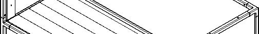
5.2.7: Fit the support profiles to the bottom
Place the frames in the right places. If in doubt ask the customer.
Groove should be facing out.
Important:
- Only install 4 support profiles if induction with downdraft goes in this module.
- Make room for pipes and drains that come up from the floor.
- If Gaggenau cabinet goes here see 8.8.
Fix the support profiles on all frames using nut and bolt.
Nut goes inside the downward facing groove. Tighten by hand for now.
M8
M8 TX40
5.2.8: Level all modules
5.2.9: Straighten the front
Level all modules. Whenever there is a support leg in the frame make sure the front is straight. Check for squareness.
5.2.10: Tighten bolts
Tighten the bolts in the support profiles using a torque wrench set at 30nm. Make sure the sides stand vertical.
5.3: Island with seating frame
5.2.11: Support profiles on worktop
5.2.12: Different aluminum profiles
Notice where the support profiles are mounted on the worktop and assemble the island-with-seating frame accordingly.
Notice length and holeplacement on the 4 different aluminum profiles as well as cutout in profile 4.
5.2.13: Assembly
Line up screw holes directly above each other.
5.2.14: Support brackets
Use the same machine screws from frame assembly to attatch worktop support brackets.
5.3.1: Attatch backpanel
7x70
Attatch backpanels.
5.4: Free standing wall frame
5.4.1: Aluminum profiles
5.4.2: Back panel


Notice length and holeplacement on the aluminum profiles. Install backpanel.


6: Cabinets
Follow these steps carefully to ensure proper installation of the V1 kitchen.
6.1: Installing the cabinets
6.1.1: Remove drawers and doors
Remove the drawers by pulling the orange handles.
Set aside all drawers and doors - protect the powdercoating.
6.1.3: Plumbing and electricity
Make cutouts in the back of cabinets if needed for easy access to plumbing and electricity.
6.1.2: Numbered cabinets

Find the numbers on the cabinets. Place cabinets on the frame in accordance with the kitchen configuration.
6.1.4: Connect the cabinets
Connect cabinets using connecting screws. Make sure the fronts align. Quickgrips are useful here.
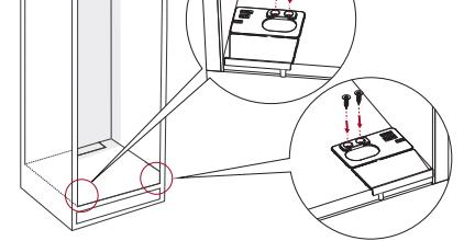
6.1.5: Large induction or sink
Before connecting large induction or sink cabinet to other cabinets fit the two screws from the sides as shown.
6.1.7: 25mm spacer
6.1.6: Gaggenau vario200 assembly
See 8.8 under appliances. 7x70 4,2x32
Use the spacer to place the cabinets 25mm from the front. The bottom of the cabinets are retracted 2mm from the sides. Make sure to measure 25mm to the sides.
Same (as 6.1.5) goes for Gaggenau vario200 cabinet.
6.1.8: Fix cabinets to frame
Fix the cabinets to the frame using self-tapping screws througt the predrilled holes.
Note: make second diagonal measurement, before securing, on wood frame floors.
6.1.9: Fix cabinets to sides
3,5x35
Fix the cabinets to the sides of the frame. 4 screws for low cabinets and 8 for tall. Make sure the distance stays at 25mm (6.1.6).
Screw into the plywood strips as shown above.
Middle of plywood strip is 50mm from front and 110mm from backpanel.
6.1.11: Cover
Install cover.
6.1.10: Power Outlets
Use a 54mm hole saw to make room for the power outlets. Cover the drawer runners to prevent sawdust from getting in.
Run the power cable throuhg the installation tunnel to the designated installation space.
7: Worktop
7.1: Installing the worktop
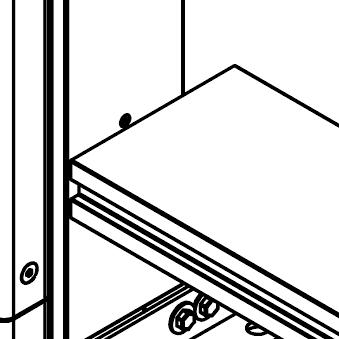
7.1.1: Fit worktop
Lift worktop onto the frame.
7.1.2: Secure worktop
Secure the worktop with screws through predrilled holes in the cabinets.
7.1.3: Adjust thw worktop
Adjust all four corners to be flush with the frame.
7.1.4: Drawers and doors
Put the drawers and doors back in place.
3,5x30
7.2: Tap installation
Vipp 901
7.2.1: Place tap and mixer
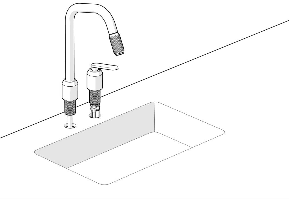
Place the tap and mixer into pre cut holes. Note that the screw on the tap base must face away from the sink.
7.2.2: Tighten from below
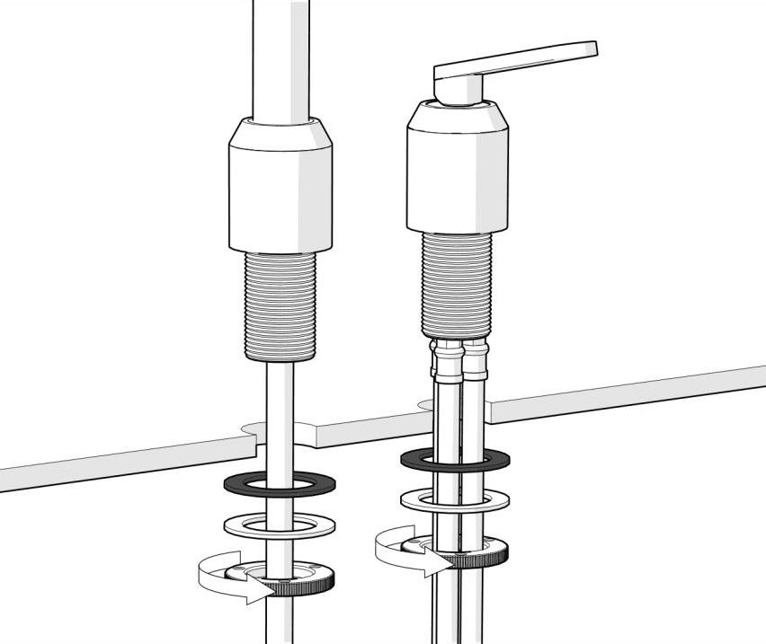
Tighten the tap and mixer.
7.2.3: Fix with screws
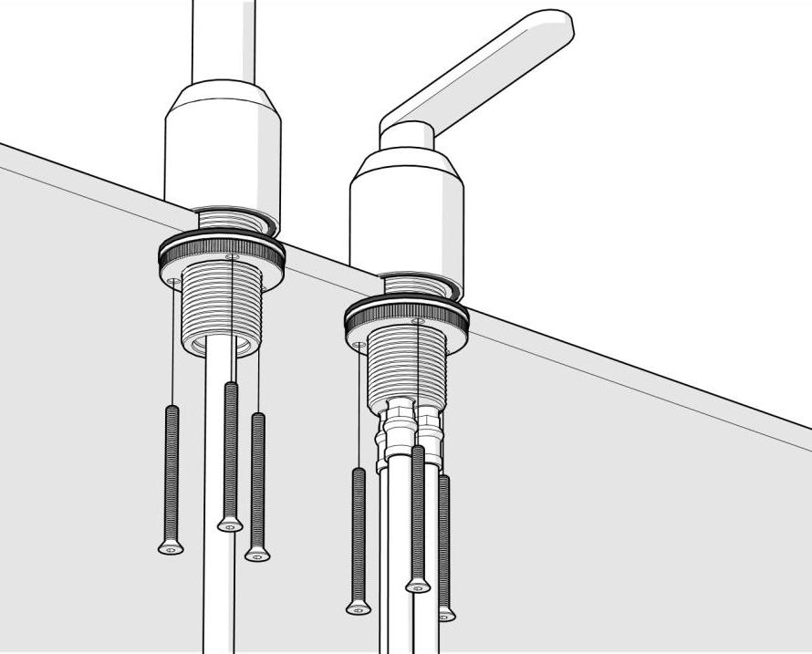
Screw the tap and mixer into place. Make sure that they sit tight.
7.2.4: Install weight
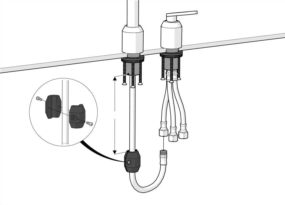
Attach the weight to the tube. Pay attention to the distance between the tap base and weight.
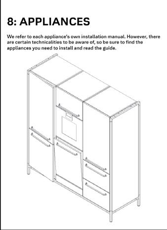
8: Appliances
We refer to each appliance’s own installation manual. However, there are certain technicalities to be aware of, so be sure to find the appliances you need to install and read the guide.
8.1: Oven
Install the oven in accordance with Miele instructions.
8.1.1: Adjust
Adjust oven in relation to adjacent fronts. 4-5mm gap on each side (~8mm if installed above dishwasher).
8.2: Full size refrigerator or freezer
8.2.1: Adjust further out
Install the refridgerator/freezer in accordance with Miele’s instructions, but keep these points in mind. 2mm
Set the foot sockets further out than what is shown in the Miele instruction. This is to make sure the fridge/freezer closes properly. Use 2mm shim.
8.2.2: Connect the doorfronts
Connect the doorfronts using the connection plate.
Keep a 5mm distance between the to doorfronts.
6,2x22
8.3: Combi refridgerator
8.3.1: Adjust further out
Install the refridgerator/freezer in accordance with Miele’s instructions, but keep these points in mind. 2mm
Set the foot sockets further out than what is shown in the Miele instruction. This is to make sure the refridgerator/freezer closes properly. Use 2mm shim.
8.4: Winecooler
Install the winecooler in accordance with Miele’s instructions, but keep these points in mind.
8.4.1: Bottom plate
4,2x25
Start by installing the ekstra 12mm base plate. Continue by following Miele’s instructions.
8.5: Gas stove
Install the gas stove in accordance with Pitt’s instructions, but keep these points in mind.
8.5.1: Before assembling
Do this at the same time as 6.1.4. When installing a large (two cabinet) gas stove; place the Pitt gas stove inside the cabinet before mounting the worktop.
8.5.2: Vipp indicator ring and knob
When lifting the stove in place, according to Pitt’s instructions, keep the gas knobs at 5-6mm as shown above.
8.5.3: Vipp indicator ring and knob

After mounting the worktop (7.1.2) and gas stove; dry fit the gas indicator rings. Put down a piece og maskingtape and draw a dot over the circles. Now you can fit the indicator rings.
8.6: Induction downdraft
Install the induction in accordance with Miele’s instructions.
8.6.1: Down draft
Start by changing the airstream direktion from 90 degrees to straight through.
8.6.2: Mount the airfilter
8.6.3: Level the induction
Mount the airfilter inside the cabinet using the pre-drilled holes. Continue by following Miele’s instructions.
8.6.4: Fit the induction
The induction should be completely level with the worktop. Use shims to get it level.
The worktop should have a 2mm gap on all four sides. Now apply black sanitary silicone.
2mm
2mm
2mm 2mm
8.7: Induction w/ rear facing air extraction
Install the induction in accordance with Miele’s instructions.
8.7.1: Cutout
8.7.2: Level the induction
Notice the cutout in the backpanel of the cabinet.
The induction should be completely level with the worktop. Use shims to get it level.
8.7.3: Fit the induction
The worktop should have a 2mm gap on all four sides. Now apply black sanitary silicone.
8.8: Gaggenau vario200
Install the cooktop in accordance with Gaggenaus instructions
8.8.1: When assembling frame
When assembling the frame, remember to slide two ekstra nuts in the suspensionprofiles and attatch the motorholder brackets.
8.8.2: Assemble cabinet
8.8.3: Before mounting worktop
Double Vario200 cabinet is assembled as such.
Lower the motor unit down on the brackets and secure with nuts and bolts.
8.9: Dishwasher, Miele
Install the dishwasher in accordance with Miele’s instructions.
8.9.1: Support bracket
During cabinet installation (6.1.6): When the dishwasher is to be installed at the far end on the right or left, start by installing the support bracket before installing the top cabinet.
8.9.3: Adjustment
When installing the dishwasher, adjust it all the way up (see how to do it in Miele’s installation guide).
8.9.2: Base plate
Install the 16mm base plate.
8.9.4: Bottom panel
When the dishwasher is installed; install the bottom cover plate. Start with hinges and then install the stop-bracket.
Adjust to approx. 8mm gap top and bottom.
8.10: Dishwasher, Fisher&Paykel
8.10.1: Support bracket
During cabinet installation (6.1.6): When the dishwasher is to be installed at the far end on the right or left, start by installing the support brackets for the worktop.
8.10.3: Install
Continue by following Fisher & Paykel’s installation guide.
8.10.2: Worktop
After installing the worktop, secure it by drilling holes in the metal-frame, through the brackets. Also install the 60mm cabinet top piece.
8.10.4: Air ventilation
The ventilation piece can be stuck to the underside of the kitchen with double-sided tape
8.11: Two oven cabinet
Move the fixed shelf down to toggle appliances
8.11.1: Remove screws
8.11.2: Remove shelf screws
If the smaller appliance is to be at the bottom, follow this guide to move the shelf.
Remove the connecting screws for the shelf on one side.
8.11.3: Remove all screws and side
8.11.4: Move shelf down
Remove all connecting screws on the other side. Then remove the side.
Move the shelf. Put the cabinet back together.
9: Finishing touch
Adjust drawers and doors. Test appliances. Remove foam and foil. Add black screwhead-coverstickers. Clean and oil worktop.
9.1: Adjusting drawers
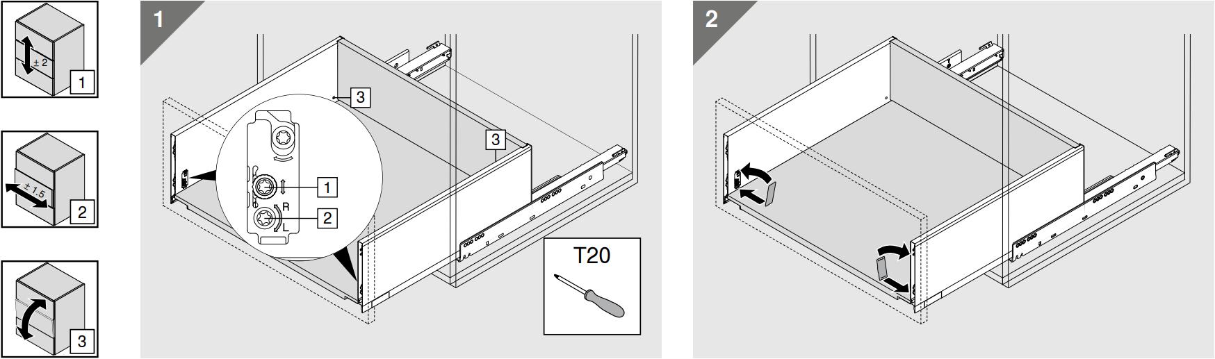
Standard drawer. Blum Movento runners, 3-way adjustable.
9.1.1: Look at the full picture
9.1.2: Sideways adjustment
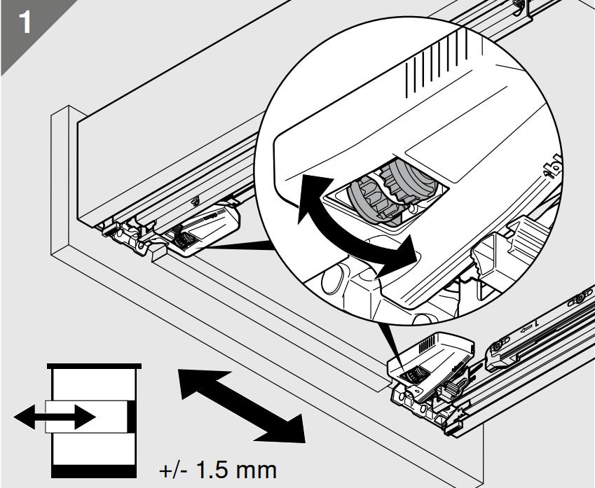
Adjust drawers to line up vertically and horisontally. Aim for 4-5mm gap.
9.1.3: Height adjustment
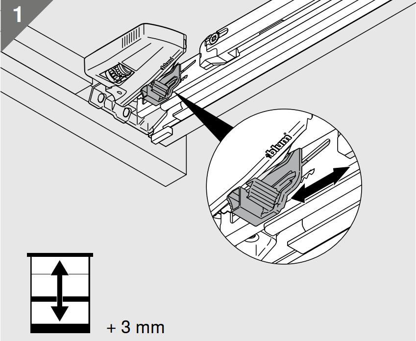
9.1.4: Tilt adjustment
Waste bin drawer.
Blum Legrabox, 3-way adjustable.
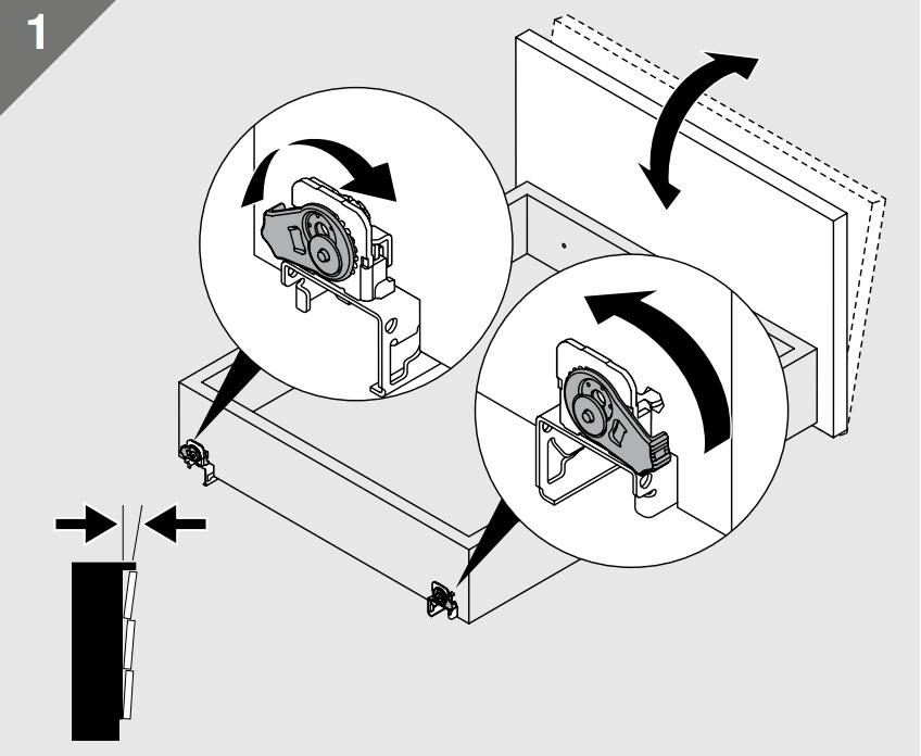
9.1.5: Empty
Empty the drawer to access the adjustment screws.
9.1.6: Height adjustment
Adjust sideways, height and tilt.
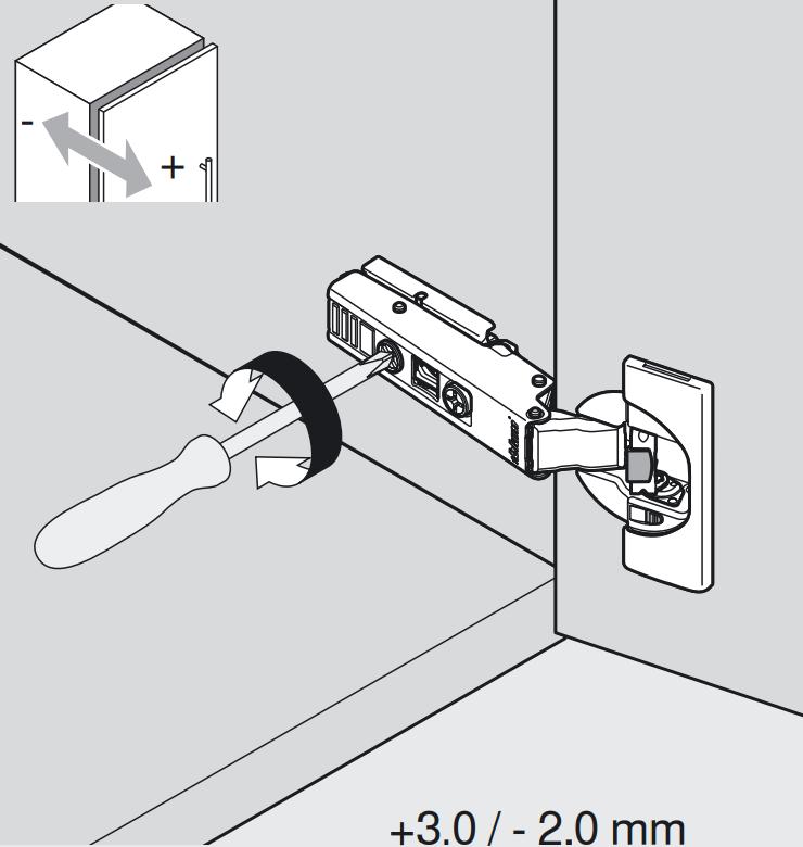
9.2: Adjusting doors
Blum Blumotion hinges, 3-way adjustable
9.2.1: Look at the full picture
9.2.2: Sideways adjustment
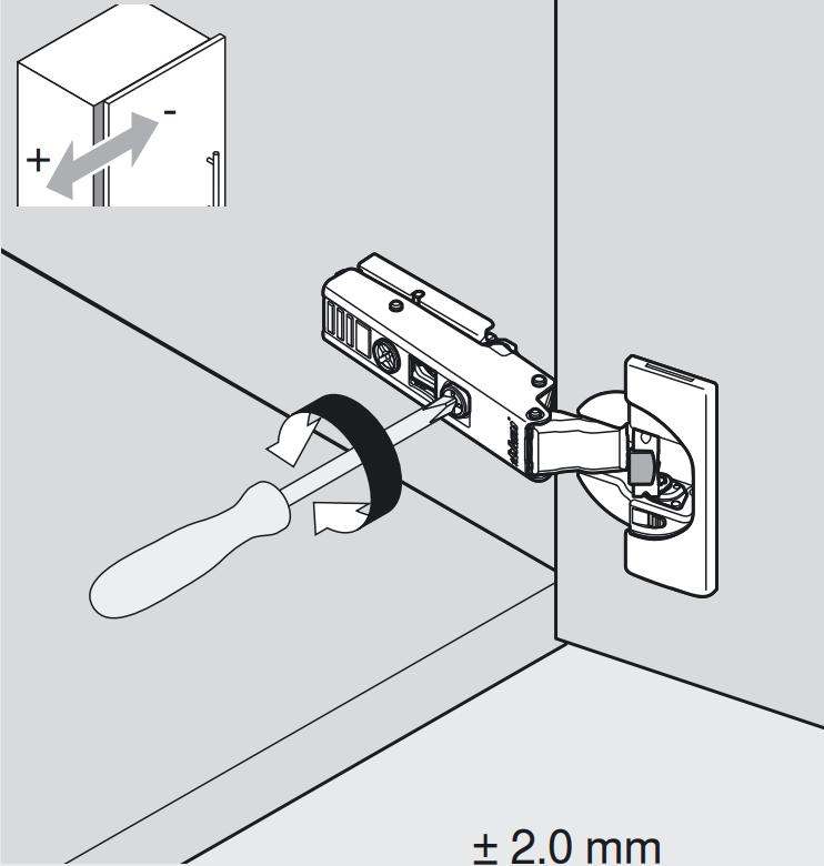
Adjust doors to line up vertically and horisontally. Aim for 4-5mm gap.
9.2.3: Height adjustment
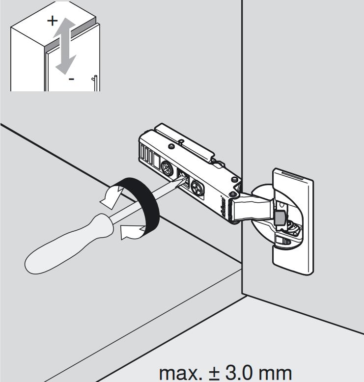
9.2.4: Closing adjustment
9.3: Finishing touches
9.3.1: Stickers
9.3.2: Cover panels
Cover screwheads with black round stickers. Fit the coverpanels in their right places.
9.3.3: Shelfs
Fit the shelves inside the door cabinets and remove wrapping.
10: Handover
Make a thorough handover to the client. Go through functions, maintenance and cleaning. We refer to the Vipp “Kitchen maintenance and care” guide in the sink cabinet or the website.