TechTalk is published by: Victorian Automotive Chamber of Commerce - Technical Services. VACC House 650 Victoria Street, North Melbourne VIC 3051
ABN: 63 009 478 209 03 9829 1111 | vacc.com.au
TechTalk Technical Editor
Rodney Lofts 03 9829 1292 | techtalk@vacc.com.au
Technical Contributors
Matthew Tan, Michael Massey, Michael Wakefield, Salvatore Cilmi and the feedback of VACC members and MotorTech subscribers.
Disclaimer This publication is distributed with the understanding that the authors, editors and publishers are not responsible for the results of any actions or works of whatsoever kind based on the information contained in this publication, nor for any errors or omissions contained herein. The publishers, authors and editors expressly disclaim all and any liability to any person whomsoever whether a purchaser of this publication or not in respect of anything and of the consequences of anything done or omitted to be done by any such person in reliance, whether whole or partial upon the whole or any part of the contents of this publication.
Information on products and services contained in this magazine is published as a service. It does not imply the endorsement of any product or service by the Chamber.
Copyright Tech Talk is copyright and no part may be reproduced without the written permission of VACC.
Subscriptions VACC adheres to its obligations under National Privacy Principles legislation.
Advertising Advertising accepted for publication in Tech Talk is subject to the conditions set out in the Tech Talk rate card, and the rules applicable to advertising.
Releasing several cars that are very similar under the skin is a deliberate, common automotive strategy. It is called platform sharing, modular architecture, or badge/brand differentiation, depending on how much the vehicles differ. The Omoda 9 (marketed as the Virtue SHS) is a large plug-in hybrid (PHEV) SUV that shares a common platform with the Chery Tiggo 9 Super Hybrid Ultimate AWD. Same platform but not the same car. Omoda and Jaecoo are two sister brands owned by Chery, marketed only outside China to support its export strategy. In Australia, the Chery brand is aimed at affordability and practicality; Jaecoo is all about lifestyle, ruggedness and adventure; while Omoda sits one step above Chery,
DIAGRAM 1 Interior upgrades
with fewer but more premiumpositioned models, focused on design, technology and a more urban, fashion-conscious identity.
Omoda 9 SHS Virtue AWD
The Omoda 9 SHS Virtue AWD (model code M38T) is Omoda-Jaecoo Australia’s flagship plug-in hybrid SUV, introduced locally in 2025 priced from $61,990 before on-road costs. It is aimed at buyers considering vehicles such as the Toyota Kluger, Hyundai Santa Fe, Mazda CX-60 and similar larger SUVs. It uses a 1.5-litre turbo-petrol engine, a 34 kWh NCM/graphite battery, and drives all four wheels through a 3-speed Dedicated Hybrid Transmission and a rear electric drive unit.
Omoda Jaecoo quotes 0–100 km/h in 4.9 seconds and a claimed 169 km
electric range, plus a claimed 1100 km combined driving range from a full battery and a full fuel tank. Charging is via Type 2 AC at up to 6.6 kW, taking a claimed 5.5 hours from 30–100%, or CCS2 DC fast charging at up to 70 kW, with a claimed 30–80% charge in 25 minutes. Even though the Omoda 9 shares many similarities with the Chery Tiggo 9 (See TechTalk May 2026 page 5923 for more details), there are some differences in service specifications. See Diagram 9 Interior features
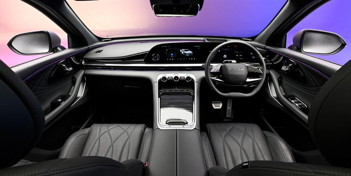
The external and internal styling are also different from the Tiggo. The interior is going for a more premium look with fancier switchgear. But in some cases, the finish lacks the refinement you would expect from a more
The interior is modern and full of technology, with some easy-to-use physical buttons. Like many other modern cars, you will have to deal with some overzealous ADAS warnings.
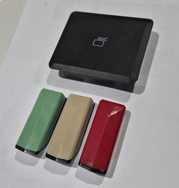
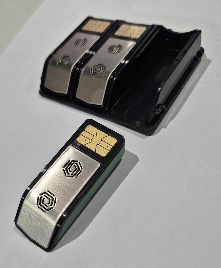
established brand. There are all the modern features you would expect, such as touchscreens, heads-up displays on the windscreen, and all the beeps and warnings from various ADAS features. But one surprise was the in-built fragrance generator system integrated with the HVAC/interior comfort system. See Diagram 2 The fragrance generator is intended to give the cabin a more “premium” smell and may also help mask odours. The Omoda 9 offers three scents: Natural, Cure, and Sport.
DIAGRAM 3 Continuous Damping Control (CDC)
DIAGRAM 4 Rear suspension view
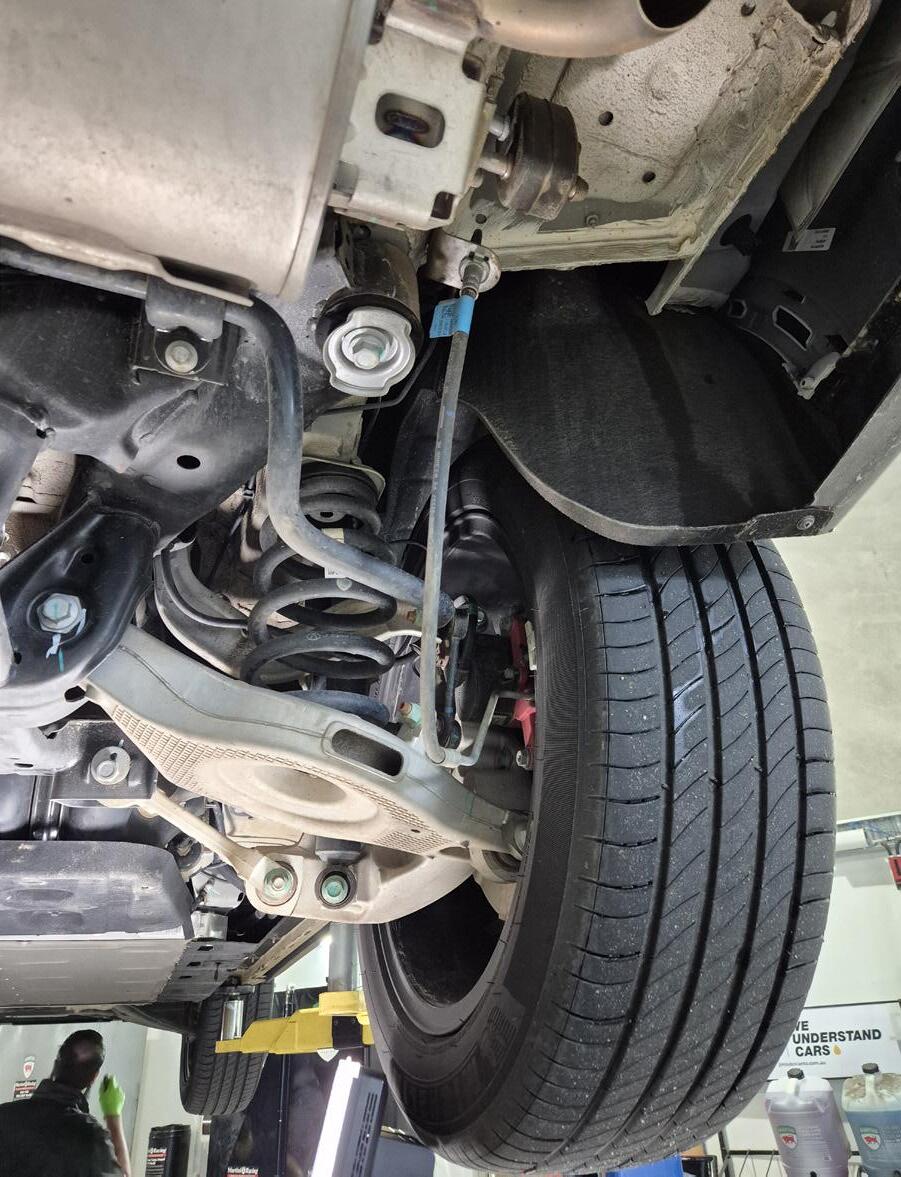
The rear suspension is similar to that of the Tiggo. When the vehicle is on a two-post hoist, the brake flexible hose is under tension.
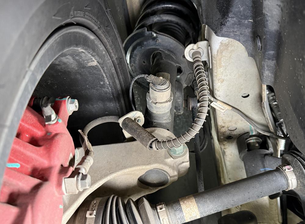
If the struts have this solenoid valve, the vehicle is fitted with Continuous Damping Control (CDC)
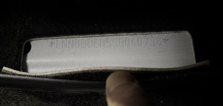
The VIN is stamped into the floor in front of the driver’s seat.
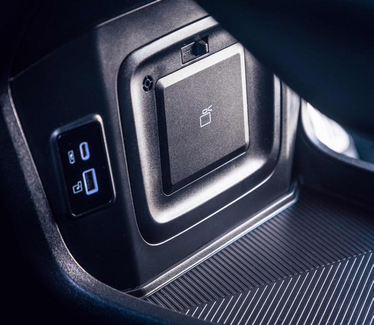
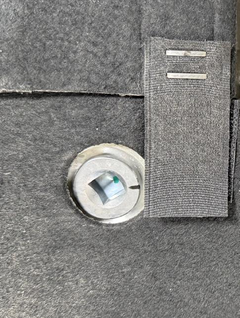
The fragrance generator is mounted under the centre console and is easily unlatched. Once the panel is removed, the three scent cartridges can be replaced by sliding them out of the panel. The car seems to monitor the levels and give a warning on the main screen if replacement is required.
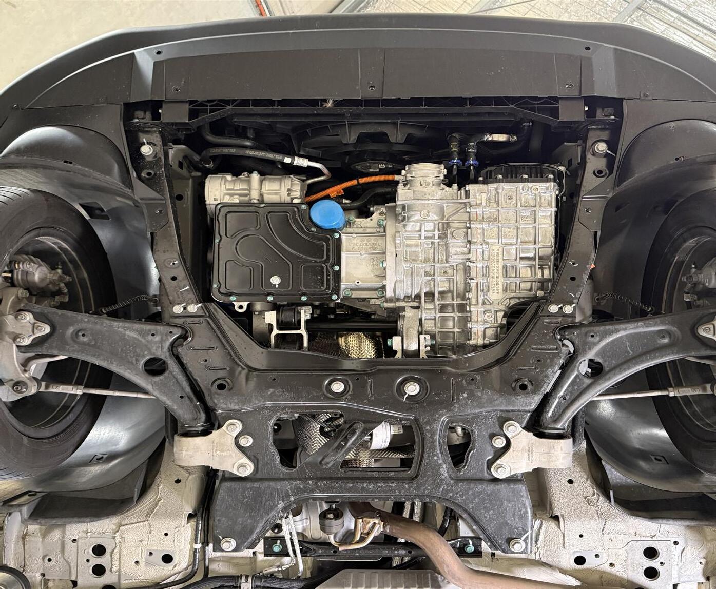
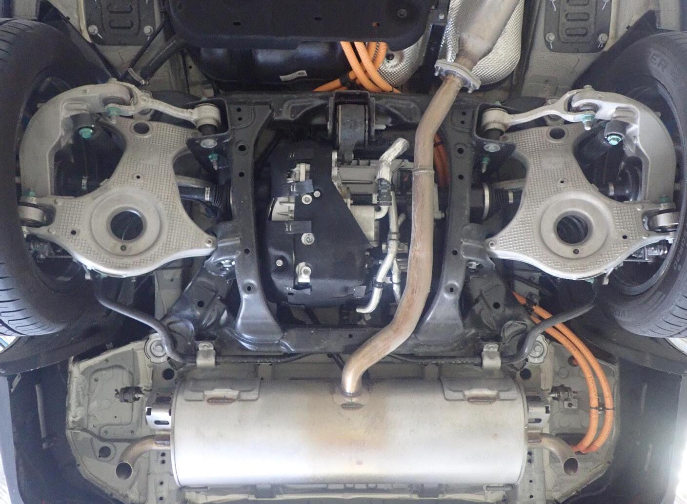
DIAGRAM 5 Service points under the front of the vehicle
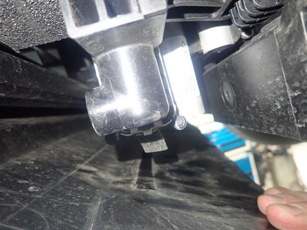
HV System Low Temperature Radiator drain plug. This is hard to access and may require the removal of the bumper.
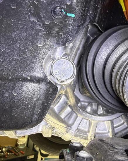
Engine oil filter
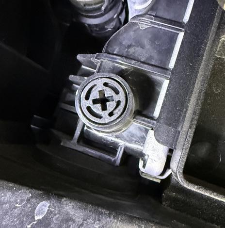
Engine radiator drain plug
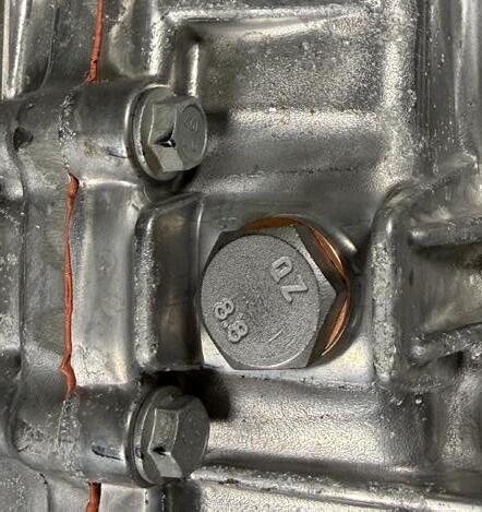
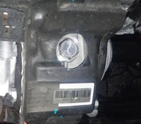
Transmission drain plug
DIAGRAM 6 Service points at the rear of the vehicle Engine sump plug
Transmission level plug
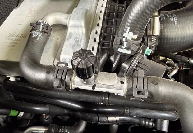
Transmission refill plug is on top of the differential housing and is best seen from the engine bay.
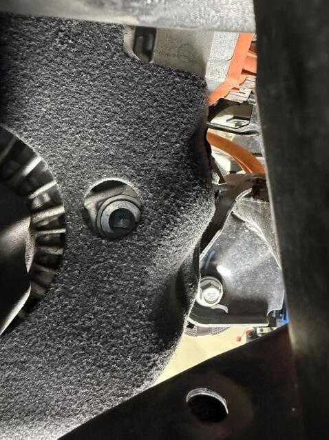
Rear motor unit drain plug
Rear motor unit filler plug
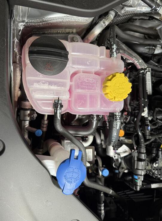
High temperature coolant - engine
Low temperature coolant - HV Systems
These scents are diffused directly through the climate control system and can be easily enabled, disabled, or swapped via the infotainment touchscreen. These types of systems are also used in other brands, such as the Mercedes-Benz AIR-BALANCE, BMW Ambient Air Package, and Genesis Mood Curator. The scent cartridges have a SIMcard style contact that will engage with matching contacts in the vehicle. There is no operational description, but it looks similar to the BMW system, which allows the car to read which scent is inserted and to monitor the levels. It might also have counterfeit detection to prevent aftermarket cartridges from being fitted. See Diagram 2 Under the car
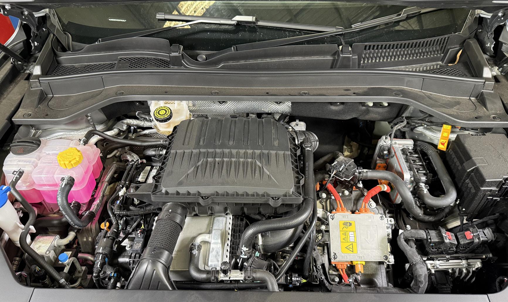
As this shares platform with the Chery Tiggo 9 the layout of components is similar but not the same. The Omoda 9 could use normal shock absorbers which have a fixed damping characteristic, which is
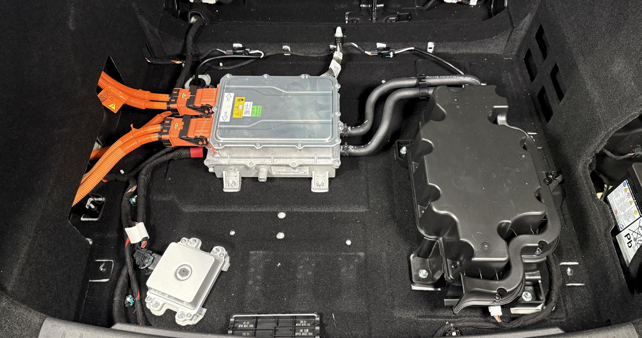
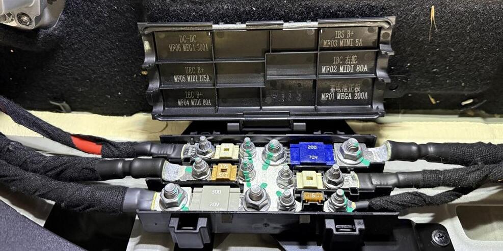
DIAGRAM 8 Component locations in the boot.
Brake fluid
VIN location - also stamped into the floor in front of the driver seat.
Coolant bleeding points
AC service points
On-board charger assembly
Sub-woofer
Electrical Vehicle Communication Controler (EVCC). This is used to swap between the various fast and slow charging protocols.
12V Battery
DIAGRAM 9 Vehicle specifications
Fluid specifications
Chery SQRH4J15
Engine Oil Specification C5 0W-20
Engine Oil Capacity 4.5L with filter
Coolant Specification OAT
High Temp Coolant Capacity 8.5L±0.5L
Low Temp Coolant Capacity 8.0L ± 0.5L
Transmission Oil Specification Titan EG DHT5105
Transmission Oil Capacity 4.7L ± 02L
Rear Drive Oil Specification Castrol 805 C EV
Rear Drive Oil Capacity 1.4L ± 0.05L
Refrigerant Type R134a
Refrigerant Capacity (Single Evap) 700 ± 15g
Refrigerant Capacity (Dual Evap) 1150 ± 15g
A/C Oil Type VC100YF
A/C Oil Capacity 183 ± 10g
Brake Fluid DOT 4
Brake specification
Front Brake Rotor Min. Thickness 28 mm
Rear Brake Rotor Min. Thickness
Wheel alignment
Front
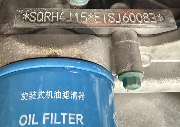
DIAGRAM 7 Engine number location
Front of engine, above the oil filter.
factory-tuned as a compromise between comfort and body control. The vehicle we inspected has Continuous Damping Control, or CDC. In plain terms, it has electronically controlled shock absorbers that can adjust how firm or soft the suspension feels while the vehicle is in motion. These can be identified the an electrically controlled valve on the
Front Lower Control Arm Bolts / Nuts
Rear Lower Control Arm Bolts / Nuts
side of the struts. The suspension control unit uses sensor information from the vehicle and adjusts the valve opening in each damper. That changes the oil flow through the damper, which changes the damping force. See Diagram 3
One thing that caught my eye when the Omoda was on the hoist was that the rear flexible brake lines were under some tension when the suspension was hanging freely on a two-post hoist, and they seemed quite exposed given how they have been routed. This didn’t stand out on the Tiggo as we checked it on a four-post hoist. This might not be a problem, but if I were servicing one, I would keep an eye on it. See Diagram 4
The fuel filter is part of the pump assembly that can be access by a plate under the rear seat.
Thank you to Chris and the team at Smarter Choice Auto in North Melbourne for their assistance with this article.
Conclusion
The Omoda 9 Plug-in Hybrid is great if you are looking for a car with a long EV commuting ability without giving up petrol touring range. It is well equipped with many luxury features that would normally only be found in far more expensive cars, but it lacks some refinement in its software and driving feel compared to the more established brands. From a workshop and maintenance point of view, nothing looks too complicated to access, and the fact that this is another vehicle from the Chery group that uses a common platform means that if you have serviced one of them, you should be familiar with the others, which will make the technician’s life easier.
Hybrid Ni-MH battery testing: What do the numbers mean?
2003-onward Toyota hybrid models • 2006-onward Lexus hybrid models
Your diagnostic tool has many features that you may not know about. One such feature is the ability to check the condition of a Toyota or Lexus hybrid high-voltage battery. Once you know how to interpret the numbers, you should be able to give your customer an overview of the battery’s condition as a part of their service or pre-purchase inspection.
As of early 2026, well over 650,000 Toyota and Lexus hybrid vehicles have been sold in Australian. The Toyota RAV4 Hybrid is Australia’s all-time best-selling hybrid vehicle, accounting for roughly a third of all Toyota hybrid sales on its own.
These vehicles use the Toyota Hybrid System (THS), which uses a unique planetary gear set acting as an electronic continuously variable transmission (e-CVT) to seamlessly split power between a petrol engine and electric motors. And from the first Prius to the current
Hybrid battery packs can be tested in the vehicle with a compatible diagnostic tool without touching any highvoltage components.
models they use the Nickel-Metal Hydride (NiMH) battery modules as the building blocks of the high-voltage traction battery of the vehicle. NiMH batteries will be the focus of this article.
With so many of these vehicles on the road and sales increasing over the last few years, it is not unreasonable for the customer to want an overview of the batterys
WARNING : High-voltage training
It is important to note that the following procedures will test the high-voltage battery in the vehicle using data from the diagnostic tool, so there will be no direct measurements of the high-voltage battery or its components. If, at the conclusion of tests, high-voltage components need replacement, this should only be completed by individuals who have completed the following courses
Battery electric vehicle training aureth101 - Depower and reinitialise battery electric vehicles vaccsdc.com.au/automotive-electric-vehicle-training/ For further information, contact us at (03) 9829 1130 or email info@vaccsdc.com.au
The OurAuto Diagnostic tool has a add on pack which can allow you to test highvoltage batteries. Contact our team for the upgrade.
condition. Luckily, the diagnostic tool you already have might be able to give you an answer once you know how to interpret the data. But first, we need to understand some terminology.
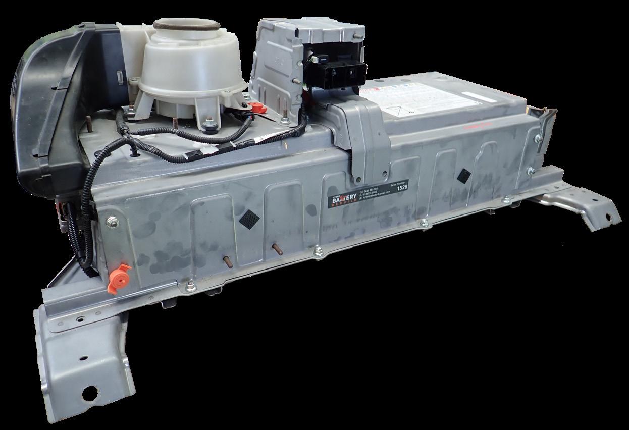
NiMH battery cells and modules
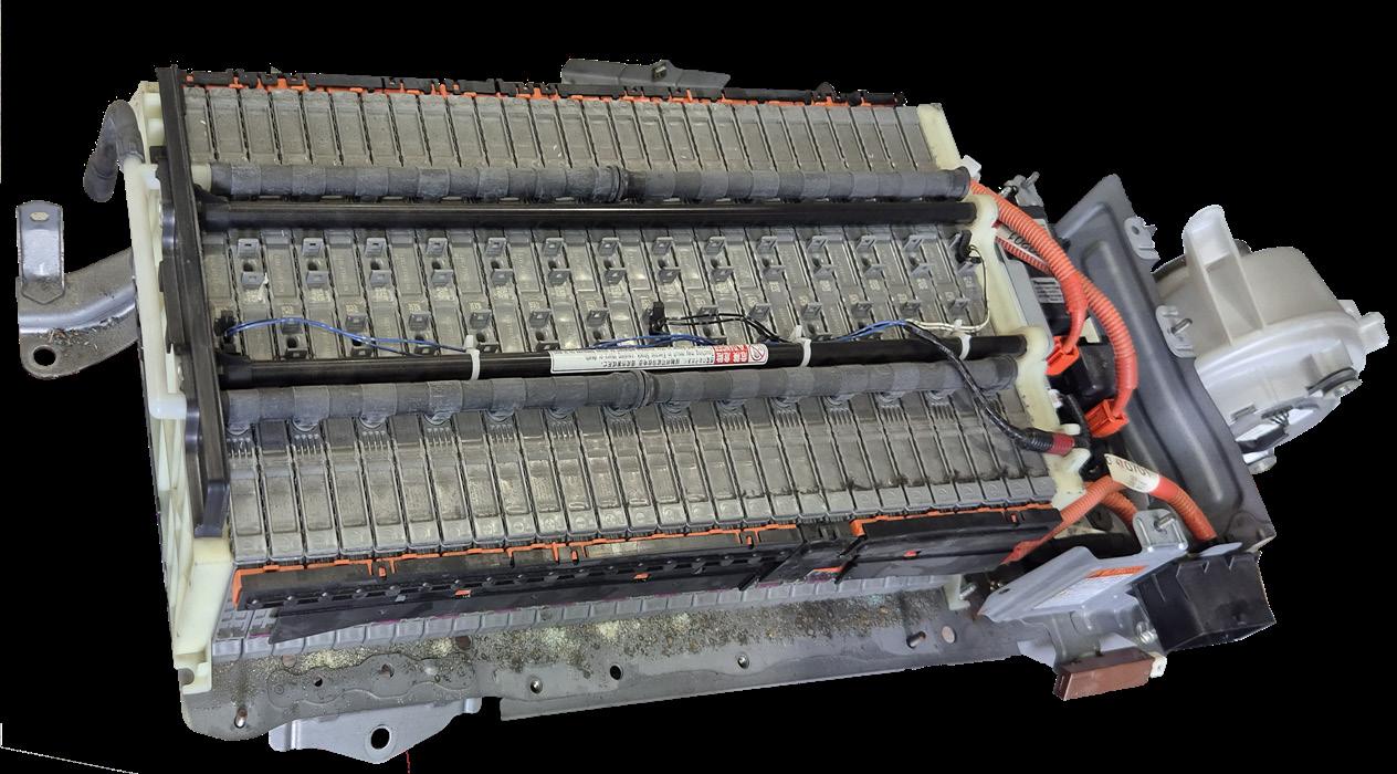
A battery cell is the fundamental, indivisible unit of a battery that stores chemical energy and converts it directly into electrical energy via a chemical reaction. A NiMH cell is a very stable, safe, rechargeable system producing approximately 1.2 volts. Six of these cells are linked together and packaged into a rectangular casing to create a battery module that produces approximately 7.2 volts. See Diagram 2
These modules are then stacked and wired in series so that their voltage outputs add together to produce the high-voltage required for the hybrid system. The number of modules can vary depending on the vehicle’s voltage requirements; the larger the car, the larger the battery pack.
DIAGRAM 1
What is a block?
2 Module Blocks Module
In many Toyota and Lexus vehicles, when you connect your diagnostic tool and read the high-voltage traction battery voltage, you will not see voltages from individual cells or modules; you will see block voltages. A block consists of two modules connected in series, with an approximate combined voltage of 14.4 to 15 volts depending on state of charge. A wire is connected at
Threaded studs where the bus bars are attached to join the modules together.
One module produces about 7.2 volts
these joints, so a voltage signal is sent to the battery management system, which can monitor all module pairs for diagnostic purposes. See Diagram 3
How to check the blocks?
The tool used in this article will be the OurAuto Diagnostic Tool with the Battery Pack testing upgrade. However, other tools may also have similar functionality, or you might
have to navigate to the battery management systems to find the correct data streams. See Diagram 1
The following tests we conducted were on a 2008 Lexus RX400H. Pre-test checks
Before testing the battery, you should check the following to provide an overview of the car and its supporting systems that could impact the battery’s test results. Identify the vehicle and battery type
As previously stated, just about all Toyota and Lexus hybrids use NiMH batteries. However, from 2026, almost all new fifth-generation Toyota and Lexus models have phased out standard NiMH in favour of Lithium-ion technology.
Battery identification is important because this article only deals with NiMH. A future article will cover how to test Lithium-ion batteries. Complete a full vehicle scan
Check for all diagnostic trouble codes that could affect the highvoltage battery, including the ECU/BMS (Battery Management System), inverter, charger, DC-DC converter, thermal management, systems. Problems with these systems can impact the highvoltage battery’s service life. Check the 12 V battery condition
The systems that manage and cool the high-voltage battery run on the vehicle’s 12-volt system. All these Toyota and Lexus vehicles still have a conventional 12-volt battery, which should be in good condition to ensure a reliable supply to the support system. Repair and replace as required.
DIAGRAM 3 Simplified overview of a Camry Hybrid battery block configuration
NOTE: There are other designs of battery module with various operational voltage ranges. See the table in diagram ? Commonly the battery management system will monitor the voltage of every pair of modules which in this case could produce between 14.5-16.5V. NOTE: Not all module are the same voltage or design and blocks can be wired differently.
DIAGRAM 4 How to access the HV battery testing on the OurAuto diagnostic tool
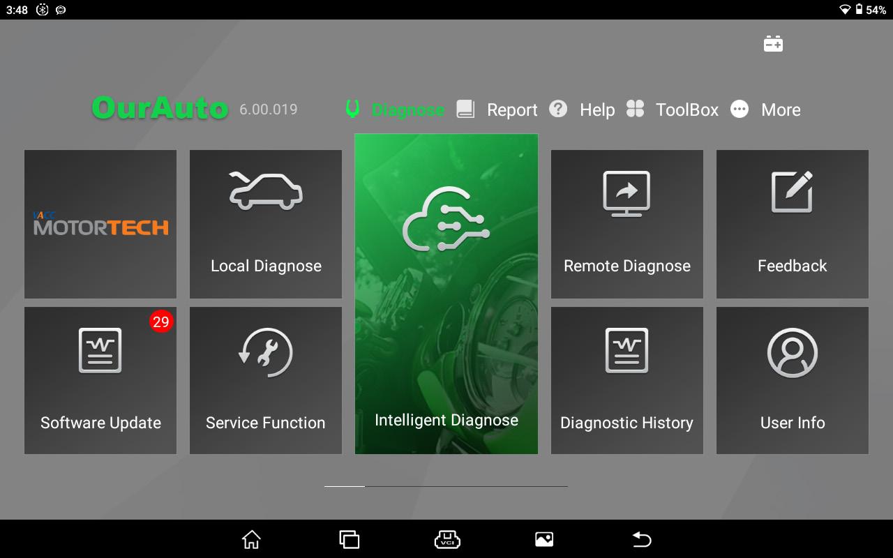
From the home page of the diagnostic tool, select the “Local Diagnose” icon.
Check the battery cooling system. These batteries are air-cooled by drawing air from the cabin through gaps in the battery pack’s modules by a 12-volt electric fan, which removes the heat generated by charging and discharge cycles. Many but not
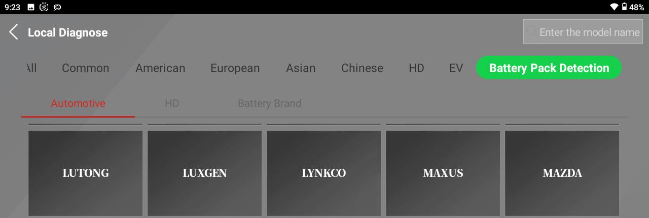
Next, select the “Battery Pack Detection” icon.
You will then have to select the make and model. Then select the diagnostic connector option to view the battery data.
all of these systems have filters or mesh screens to prevent hair and lint from entering the battery. These filters can block and should be cleaned or replaced regularly. Check the condition of these filters; if they are blocked, this is not a good sign, as heat can damage
DIAGRAM 5 Battery test data at rest - Lexus RX400h
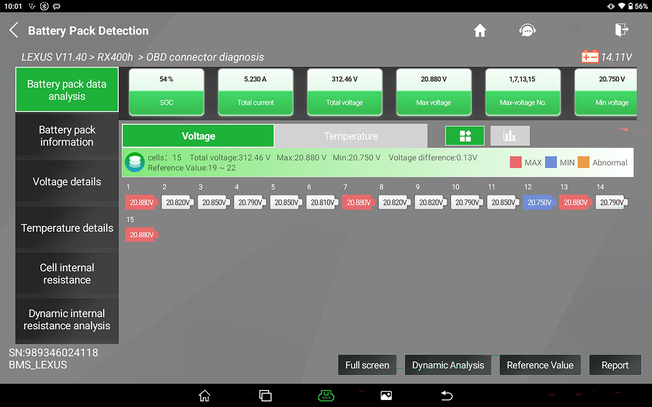
State of Charge must be over 50%
The voltage difference or delta will give you an indication of the battery’s balance. The smaller the difference the better.
these batteries. See the following article for more information.
Hybrid Battery Cooling
System Service
TechTalk April 2021 Page 5024
Lexus Hybrid Battery
Vent Servicing
TechTalk March 2022 Page 5186
This is a view of the battery blocks and the colours will change as their SOC changes
Screenshot the data with this icon.
Use this button to enter the voltage range of the battery type you are testing. Use the table in Diagram 7
Battery test data at rest
1. With the vehicle turned on, you should see “Ready” on the instrument cluster, indicating that the vehicle is ready to drive. The following tests will not work if only the ignition is on.
2. Connect the OurAuto diagnostic tool, navigate to “Battery Pack Detection”. See Diagram 4
3. Then select the make and model. Then select the OBD connector option.
NOTE: For other diagnostic tools, the OE information states you could navigate to “Hybrid Control ECU” or HV Battery ECU, depending on model, then select “Data List” or “Live Data”.
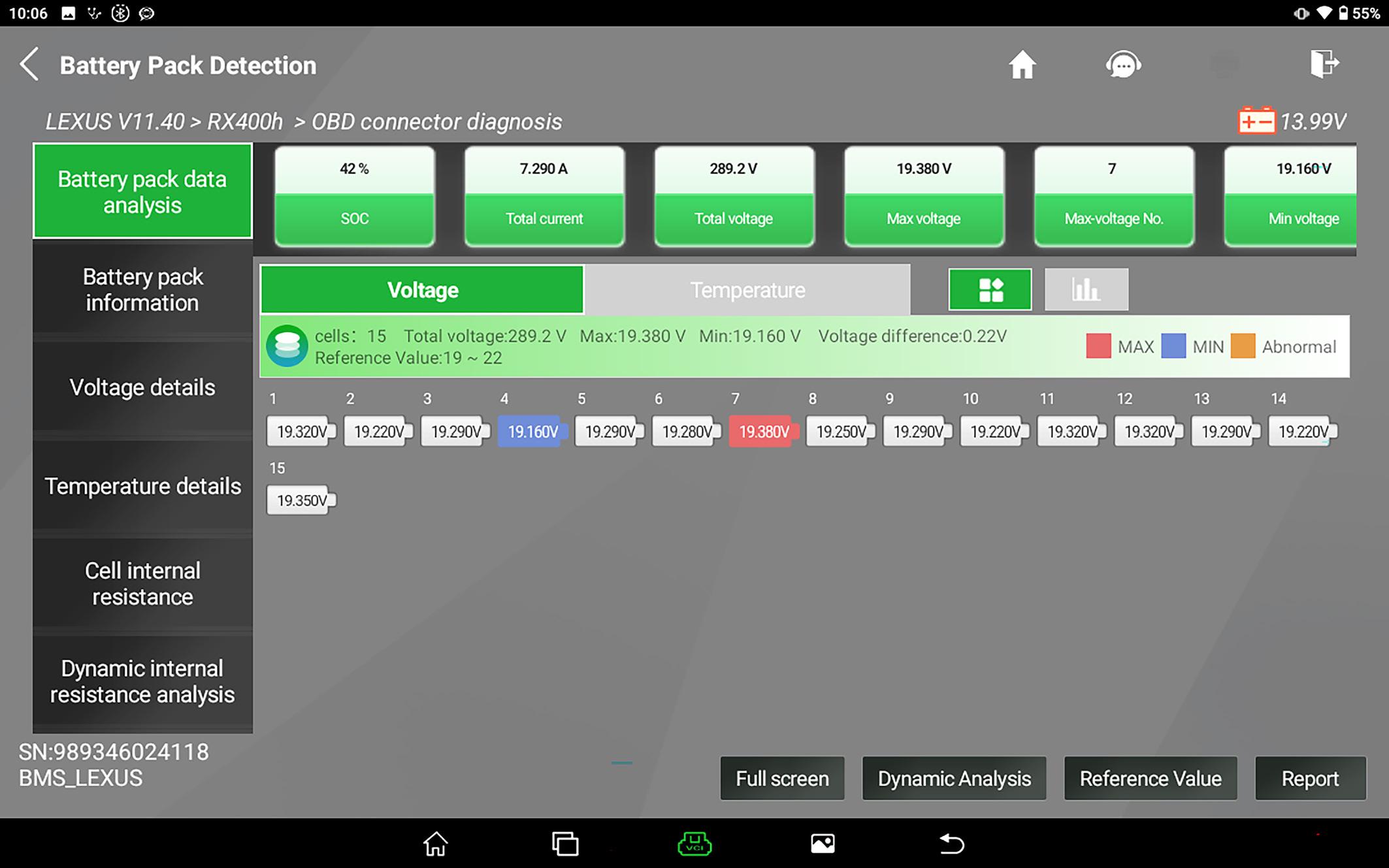
4. The OurAuto diagnostic tool will display a page of data titled “Battery Pack Detection” with all of the data you need to assess the battery. See Diagram 5
5. First check the battery data to ensure it matches expectations. Check that the number of
blocks and the voltage range in the diagram match the model. Refer to the table in Diagram 7
6. You can use the “Reference Value” button in the bottom left corner to enter the voltage range of your battery, so when the test is running, it will more easily show any abnormal block voltage.
7. Next, check the State of Charge (SOC) percentage in the first box in the top row. It should be at least 50%. If not, allow the engine to run or take the vehicle for a drive to increase the SOC.
8. In the middle of the screen will be the “Total Voltage” reading, which is the combined voltage of all the blocks. “Maximum Block Voltage” is the block with the maximum voltage, and “Minimum Block Voltage” is the block with the minimum voltage at that moment.
9. The important reading is the “Voltage Difference”, which is the difference between
DIAGRAM 6 Battery test data under load - Lexus RX400h
With the transmission in Neutral and load on the vehicle you should have about 7 amps of discharge.
Stop the test when the max voltage is at the lower end of the operational voltage range.
A battery in good condition will have the max and min voltages change around the blocks. If one block remains the minimum voltage this block is weak.
the Maximum and Minimum block, which gives us an indication of the level of battery balance. See Diagram 5
10. The images of the battery blocks in the middle of the screen will show which block has the maximum and minimum voltage, and if the battery is in good condition, the maximum and minimum blocks should change as their SOC changes. If one block remains the lowest, this could be a problem. You can change this to a bar graph view if it is easier to see the differences. See Diagram 9
11. We suggest that you record this data or screen shot the page at this point for future reference.
Battery stress test
Next, we will put the battery under load and see how the data changes.
1. While sitting in the driver’s seat with the vehicle in “Ready”, apply the park brake and press the brake pedal.
The voltage difference will increase under load. Check the results against the table in Diagram 8
Alphard (2011-3/2015)
Camry (2012-2017)
Camry (2018-2020)
Corolla Axio (2013-Present)
Corolla Fielder (2013-Present)
Corolla
Crown
Harrier (2005-2012)
Prius C, Axio/Fielder (2012-2020)
Vellfire (2011-2015)
Vellfire (2015-Present)
Vitz (2017-Present)
*These batteries have uneven block configurations. See Diagram 9
2. Place the transmission into Neutral. This will disable the vehicle’s ability to recharge the traction battery, so the engine will not start. There will be a notification on the centre screen and a warning tone which is normal.
WARNING: Don’t leave the vehicle in this state unattended, as it will discharge the traction battery beyond its normal levels.
3. Now turn on all of the electrical loads. Turn on the high beams and the rear demister and adjust the A/C to the lowest temperature with the fans set to maximum. Check the “Total Current” reading in the second box in the top row of the diagnostic tool. It should be over 5 amps and preferably between 7-9 amps. It should be a positive indicating discharge, a negative value shows charging. See Diagram 6
4. While the battery is discharging, check which blocks have the Maximum and Minimum voltage; if they are in good condition, they should change constantly. If a block remains at the minimum voltage at idle and under load, it indicates that the block is weaker than the others.
5. As the SOC reduces, the Voltage Difference may increase, which is normal. However, if this difference becomes too large, it indicates the battery is out of balance, which will eventually trigger fault codes in the battery management system.
6. Record the results from the diagnostic tool.
7. Refer to the following table to assess the reading and judge the condition of the battery. See Diagram 8
8. Once the minimum operating voltage range is reached, stop the test by placing the transmission back into Park and allow the engine to start charging the battery. When the engine stops on its own, turn off the vehicle.
Not all blocks are the same size
The above test works well when all blocks are wired the same way. However, for reasons only known to the engineers, some hybrid batteries
Lexus
DIAGRAM 8 NiMH Battery Voltage Difference / Delta
Max. Voltage Difference Condition
Below 0.2 V
As new battery
Between 0.2 -0.3 V Healthy battery
Between 0.3-0.4 V Okay battery
Between 0.4-0.5 V Emerging battery failure
Between 0.5-0.8 V Battery is close to failure
Above 0.8 V Battery has failed
These figures are based on industry experence and should be used as a guide in combination with DTCs, internial resistance and temperature sensors output to assess the battery’s condition.
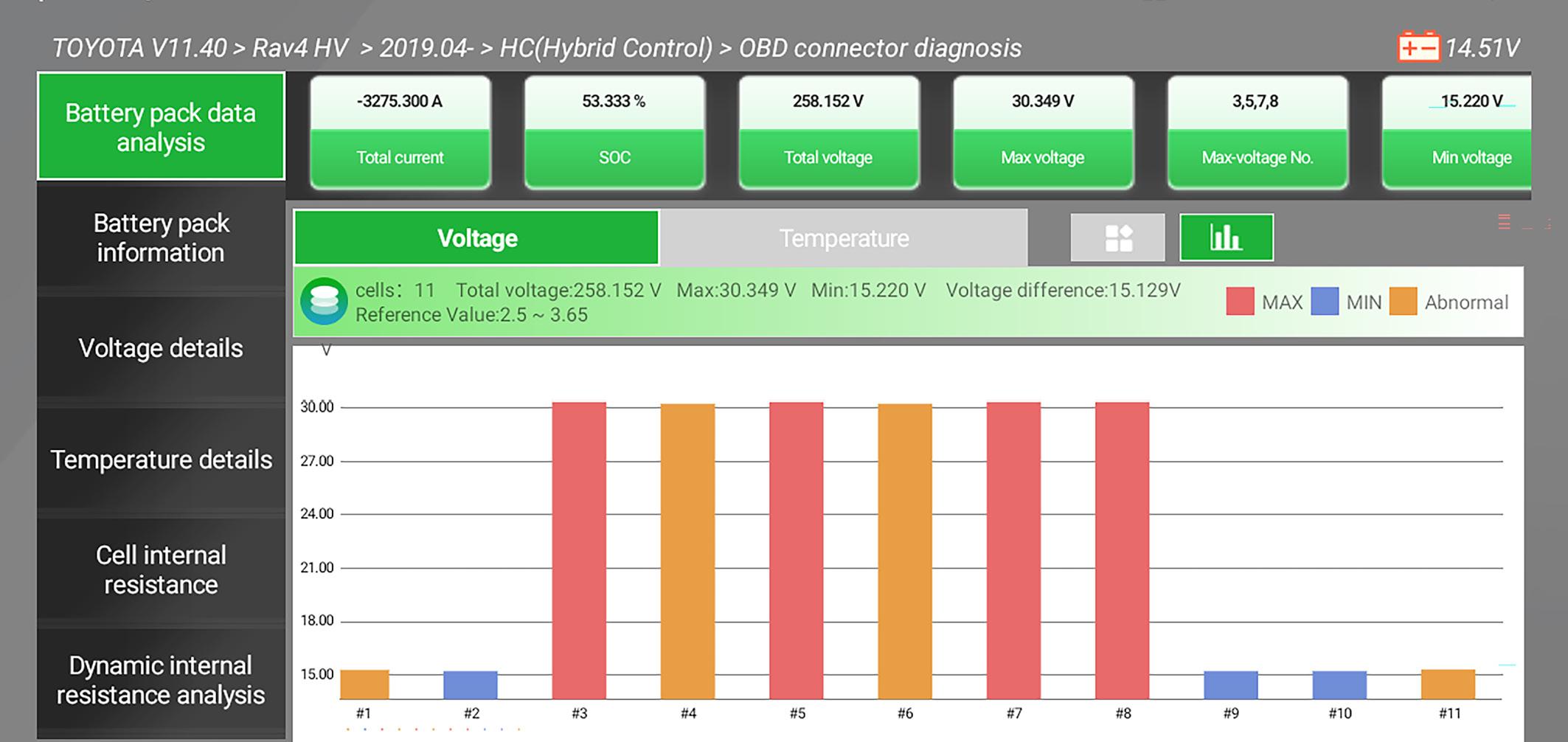
use differently sized blocks for voltage monitoring within a single battery pack. Some blocks will have two modules joined, while others will have four. This means that the data shown on the diagnostic tool will be about 15 volts for some blocks and around 30 volts for others, making interpretation tricky because the “Voltage difference” displayed on the tool will be at least 15 volts. Therefore, you will need to do some creative maths to calculate the actual voltage difference and assess the battery’s condition. See Diagram 9 2 Module Block Battery Voltage Sensor Configuration
DIAGRAM 9 Simplified overview of a RAV4 Hybrid battery with a mixed block configuration
The battery management system monitors the voltage of some modules in pairs and others in groups of fours. This will make working out the battey voltage balance difficult as some block will be about 14.5-16.5V and others 30V. This is a common configuration in RAV4 and Kluger.
You can swap the voltage view to a bar graph with this button.
Temperature details.
The OurAuto tools can display readings from the battery’s temperature sensors. Most batteries will have many temperature sensors, and you should check that they are all reading within a similar range. If there is significant variation, it could indicate a problem, even if it is not severe enough to trigger a diagnostic code.
Internal resistance
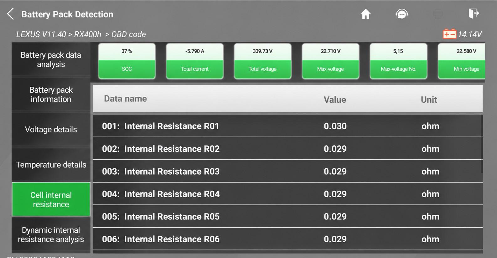
The OurAuto Diagnostic tool also offers the option to measure the block’s internal resistance. It represents the extent to which the block resists current flow during charging and discharging. A higher internal resistance causes greater voltage drop under load, more heat generation, reduced power delivery, and can indicate battery ageing or deterioration. As a rough rule of thumb for blocks with a voltage range 14.5-16.5V is about 5 milliohms (0.005Ω) would be considered a good block resistance, while 10 milliohms (0.01Ω) would be considered too high and could trigger fault codes. However, the RX400h has a different module design with a higher voltage range of 19-22V. A good reading would be 20–30 mΩ, which lines up with our results. See Diagram 10
Test results
From the test result on the 2008 Lexus RX400H with 240,000km on the clock, it has a 0.22V voltage difference under load. Compared to the results table, the battery appears healthy and in good condition, and, as far as we know, it is the original battery. Provided that the vehicle is used regularly and the air vents are serviced, there is no obvious reason that this battery will not last for years more. See Diagram 6 &8
NiMH battery life span
Based on trade experience, earlier hybrid batteries tend to have a longer battery life, sometimes exceeding 500,000km, while later models might only get 200,000km. The
With this button you can see the internial resistances of the battery blocks. This can give you more information to base you assessment of the battery’s condition.
The batteries are basically the same across the generations, but it seems that the software has changed to improve fuel efficiency, which puts the batteries under more stress which tends to reduce battery life.
battery packs are essentially the same, but it seems that the battery management system software in later models allows the battery to be used more by increasing the depth of discharge (DOD), which improves the vehicle’s fuel efficiency. Allowing the battery to discharge deeper and more often tends to reduce its service life. See Diagram 11
The best way to get the most from a NiMH hybrid battery is to protect it from heat and imbalance. Keep the cooling vent and fan clean, use the vehicle regularly, maintain the vehicle correctly, and repair any faults that cause excessive battery cycling or high battery temperature. If your tests indicate that the battery condition is degraded by voltage imbalance or internal resistance, or that the vehicle has battery or hybrid-related diagnostic codes, you have options. You could send the vehicle to the dealership for
resolution, or there are various businesses that have experience in battery replacement. Alternatively, if your staff have completed the appropriate high-voltage courses, you could fit a new or reconditioned battery from several different suppliers. We are aware of several VACC MotorTech subscribers who can rebuild hybrid batteries inhouse. You will have to use your professional judgment on which is best for you and your customers. With the features of the OurAuto Diagnostic tool, you can now interpret data from a vast number of Toyota and Lexus hybrid vehicles and give your customers the peace of mind about the condition of their high-voltage battery. For more information on the OurAuto diagnostic tool and the MotorTech High-voltage data package, log onto VACC MotorTech or call VACC’s TechAdvisory Service.
thank you to Joel and the team at Infinitev for their assistance with this article.
DIAGRAM 10 Internal resistance of blocks - Lexus RX400h
DIAGRAM 11 Toyota Camry battery approximate lifespan over series
RHF door wiring fault
We like it when our VACC MotorTech subscribers share feedback on common faults they have encountered. In this case, it is a Nissan T32 X-Trail with intermittent power window and electric mirror faults, with a cause that might apply to other makes and models. But there could be a complication with some aluminium wires you should be aware of.
The Nissan X-Trail is one of the longest-running and most successful nameplates in the highly competitive Australian medium SUV
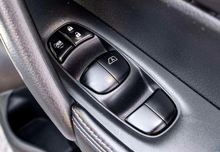
segment. First launched locally in 2001 with the T30, it was replaced in 2007 by the T31, which ran until 2014. The T32 was released in 2014 and superseded by the T33 in 2022. Power windows and mirrors have been a common feature in many makes and models and are a popular option. However, the downside of these systems in older vehicles is the bundle of wires that have to pass from the master switch in the door into the vehicle body and then to the other doors. See Diagram 2
Multi-stranded copper wire is used in automotive applications as it is a resistant metal to fatigue caused by the movement and vibration of the car.
Metal fatigue
Metal fatigue is the weakening and eventual cracking of a metal component caused by repeated, fluctuating mechanical stresses over time. Even if these individual stresses are far below the metal’s maximum breaking strength, the cumulative effect of thousands of microscopic bending cycles causes small micro-cracks to form, grow, and eventually snap the material.
Automotive engineers use several specific design strategies to prevent metal fatigue in vulnerable vehicle wiring harnesses. Copper alloys are specifically heat-treated (annealed) to maximise ductility. This process makes the metal softer and more resistant to work-hardening when bent.
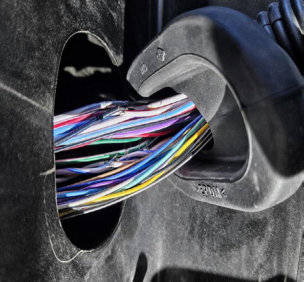
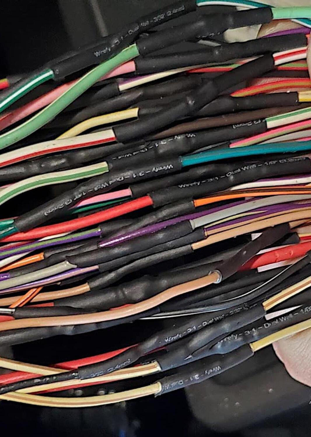
Also, the wiring harness in automotive applications are made of fine, multi-stranded copper wire rather than solid-core wire. More strands increase overall flexibility and spread the bending forces across many tiny wires. See Diagram 1
The trouble
One of our VACC MotorTech subscribers shared their experience with three different T32 X-trails, all of which had intermittent electrical faults in the electric windows and mirrors. They found that the situation could change depending on whether the driver’s door was
DIAGRAM 1 Common automotive wires
DIAGRAM 2 Common area of broken wires in the door wiring harness
The wiring to the driver’s door in the T32 Nissan X-Trail is a common failure point, as the wires can break from fatigue. This is also a common failure point on many other makes and models.
However, if you look closely, the wire strands don’t appear to be copper. If you see wires with a base insulation colour of lavender, they are aluminium-core wires.
open or closed, with some circuits starting to work again or failing.
On inspection of the wiring boot that goes between the body and the door, they gave it a squeeze and felt broken wires poking into
the rubber boot. In all three cases, the opening and closing of the driver’s door eventually fatigued the wiring to the point that the wires began to break, causing the circuits to fail. See Diagram 2
DIAGRAM 3 Power window master switch connector
The Aluminium Complication
Aluminium wire is increasingly used in modern automotive wiring harnesses as it weighs about 66% less than copper and is cheaper. Unfortunately, it is also more brittle and prone to breaking
Lavender (LA)
DIAGRAM 4 Crimping tool
Nissan recommended using a crimping tool with the correct splice connector to join aluminium wires. The splice connector will pierce the oxidation layer on the aluminium wires for a good electrical connection.
than copper under high vibration, typical of automotive applications. The T32 workshop manual states that wires with aluminium cores will have lavender-coloured insulation (Colour code LA for the base colour, but could have additional trace
DIAGRAM 5 Soldered wire joint
colours). Lavender is a light violet or purple colour. See Diagram 2
The next complication is that aluminium forms an invisible, tough aluminium oxide layer the instant it is exposed to oxygen, which makes soldering difficult
When soldering a wire, the solder flows into the wire’s strands, forming a strong joint. Unfortunately, this joint is now solid, which makes the wire strands next to it more prone to breaking.
How to join aluminimum wires
To repair aluminium wiring, Nissan recommends using their dedicated harness repair kit and crimping tool (SST KV9911260). This kit uses specially engineered terminals with sharp internal ridges that bite through the aluminium oxide layer as the tool compresses them, sealing the connection cleanly and preventing oxygen from entering. Once the joint has been completed, cover the crimped joint with heat-shrink insulation that you had slipped over the wire before joining them.
Our research on this topic has failed to find an aftermarket supplier that specifically mentions that their crimping tools and slice connectors are compatible with aluminium wires. See Diagram 4
Soldering
Not all of the wires in the door wiring harness appear to be aluminium, as copper wires are easy enough to repair with solder. The primary advantage of soldering wires together is that it creates a permanent, high-strength, low-resistance, and corrosionresistant joint that is slim when
WORKSHOP EQUIPMENT & DESIGN
DIAGRAM 2 Areas to join the wires for a reliable repair
to penetrate the oxidised layer to achieve a strong, reliable bond. Unfortunately, the solder wicks up the wire, creating a solid point. This removes all the metal fatigue-reducing advantages of the multi-core wire, making this joint prone to snapping under vibration. See Diagram 5 Best practice to repair door wiring
For a reliable repair, it is recommended to add extra new wire to the harness at the break point to allow the joins to be tucked into the door and into the body of
Don’t join the wires in the boot. The flexing will cause the wires to break again soon.
the vehicle. This will allow the new wire to run through the harness boot, where bending and flexing will occur, while the soldered joints remain stationary. See Diagram 6
The feedback we have received indicates that there might only be a few broken wires to start, but as you move other wires out of the way for inspection, more break. Some recommend replacing all wires running through the door boot with copper wire to prevent future problems. Some cut and join the wires; others back out the terminals at the connectors and replace all the wires and connector terminals. You will have to use your professional judgement to decide which method is most reliable for repairing your customer’s car.
Broken wires in the driver’s door boot are a common cause of issues with the power windows and mirrors in the T32 X-Trial, but they are not the only possibility. VACC MotorTech has the wiring diagrams for these circuits within the HaynesPro data, or via the VACC’s TechAdvisory Service.
It is recommended to insert additional wire between the broken ends so that only the new wire is inside the door boot. Give yourself enough length so that the joins are well inside the body and the door where they will not move or flex.
Vehicle Identification Numbers: The different standards
Identifying a vehicle correctly is essential for ordering parts and finding the correct service and diagnostic information, and most cars will have various numbers and plates to help you, but it can be confusing. The Vehicle Identification Number or VIN is an important piece of the puzzle, but it is ot the total answer.
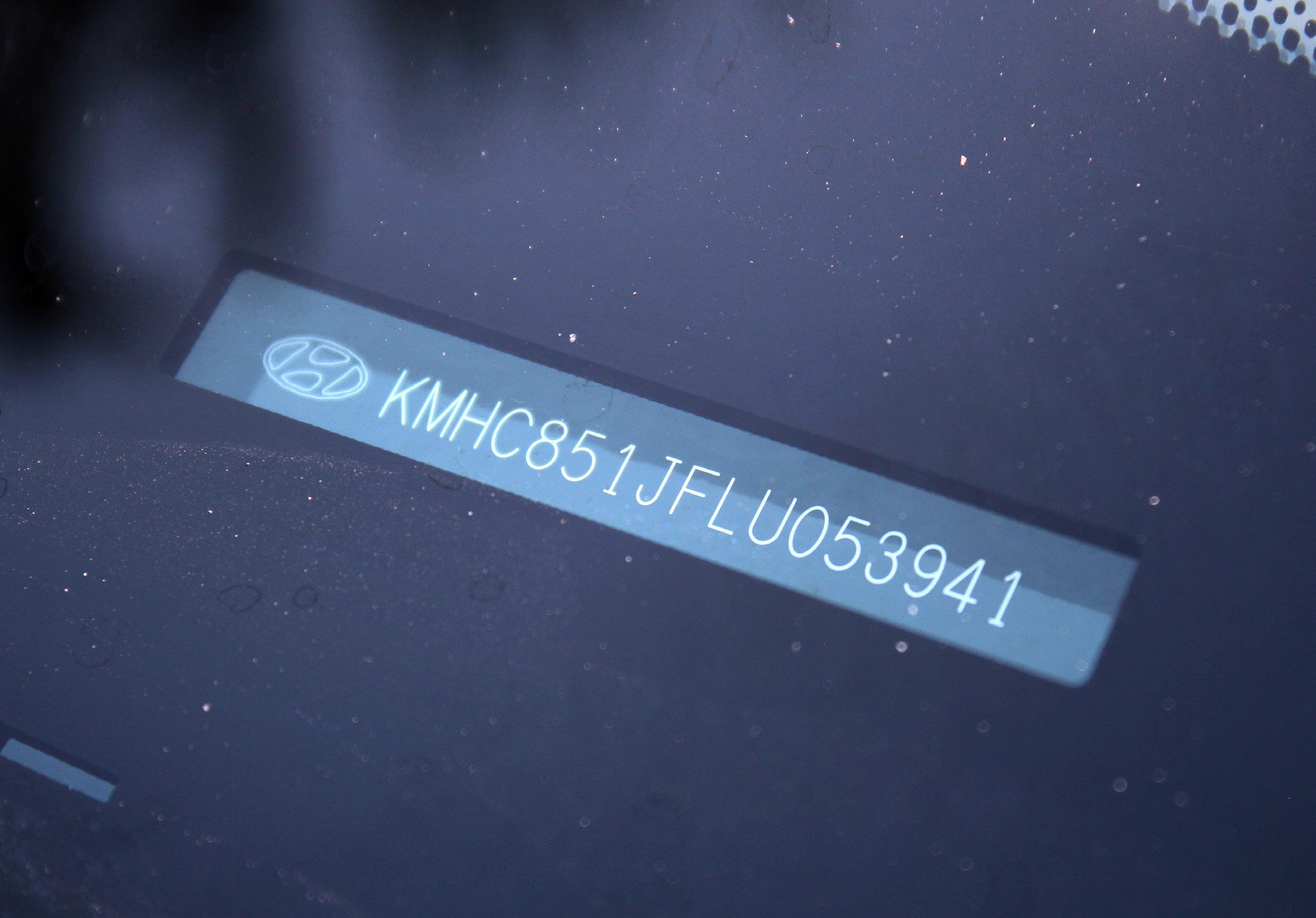
The first VINs were used in the USA in the 1950s, but there was no standard across manufacturers, and they were little more than a serial number. The Europeans were having the same issue. So, the International Organisation for Standardisation (ISO) created an international standard that defines the content and structure of the Vehicle Identification Number (VIN). It establishes a uniform 17-character, globally accepted “fingerprint” used by the automotive industry to uniquely identify motor vehicles, trailers, and motorcycles called ISO 3779.
The basic rules of the 17-character ISO 3779 VIN
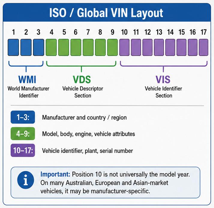
To comply with ISO 3779, the first three positions are the World Manufacturer Identifier (WMI) that identifies the manufacturer and the country of origin. Positions 4–9 comprise the Vehicle Descriptor Section (VDS), which describes the vehicle’s general attributes and characteristics, such as body style, engine type, model, and restraint systems. The exact meaning of these characters varies by manufacturer. Positions 10–17 are the Vehicle Indicator Section (VIS) that provides unique identifying information for the specific vehicle. The exact meaning of these characters varies by manufacturer. See Diagram 1
There are character rules to prevent confusion and visual misreadings. Only upper-class letters and digits are allowed. The letters I, O, and Q are strictly prohibited because they are too similar to the numbers 1 and 0, which are allowed.
The FMVSS 115 North American Standard
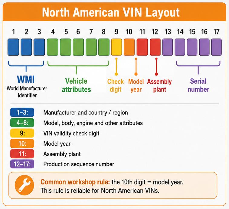
In the 1980s, the 17-character VIN based on ISO 3779 was introduced in the USA, but unlike the flexible ISO guidelines, the layout of all 17 characters is legally fixed across all manufacturers. See Diagram 2
Positions 1-3 are the World Manufacturer Identifier (WMI). Positions 4 to 8 comprise the
DIAGRAM 1 ISO VIN
DIAGRAM 2 FMVSS 115 North American VIN
DIAGRAM 1
DIAGRAM 2
Vehicle Descriptor Section (VDS), which contains specific attributes, including body type, engine code, series, and occupant restraint type. Position 9 is a single digit (0–9) or the letter “X” calculated via a complex algebraic formula. This serves as a security feature that instantly exposes counterfeit or mistyped VINs. From this point on, it becomes the Vehicle Indicator Section (VIS).
Position 10 is a single character code representing the exact model year. The code repeats every 30 years, so it must be interpreted in conjunction with the vehicle’s age, model generation, compliance plate, build plate, or OEM data. See Diagram 3
Position 11 is the code that designates the specific manufacturing or assembly facility. Positions 12-17 are the sequential production order, or if manufacturers make under 1,000 units/year, positions 12–14 act as a secondary manufacturer extension. More than one international standard
So, there are two main international standards that can be used across a wide range of cars from many manufacturers. There doesn’t seem to be a hard-and-fast rule about which manufacturers use which system, as it seems to depend on the market.
European vehicles made in Europe will commonly use the ISO standard. Cars made in or for the North American market will use the North American standard. Vehicles that arrive in Australia could have either. The same manufacturer
can use either system depending on where the vehicle was built and the market it was built for.
The Trouble
So, the VIN may or may not give you the year of manufacture, depending on the VIN standard used. To get all the details you need for service and repair information, you will need to use the VIN as a starting point to get the required information, not the final answer. Commonly, you will have to look for a compliance plate in the door jam, which may give you the build date. Some vehicles may include a data card that can be attached to the vehicle or placed on the front page of the owner’s manual. But many modern vehicles only have an electronic version of this data card. There are various online VIN decoders, but our experience indicates they don’t work for all year models, especially newer vehicles. If this is the case, you could contact the dealerships, and they may provide you with a vehicle data list or card. This might take some time, but if you are working on this vehicle regularly, it could be time well spent. For information on the location of Vehicle Identification Numbers, Engine Number and other identification details on many makes and models, log on to VACC MotorTech or call VACC’s TechAdvisory Service.