Gabriel Vollin_Y4 | Unit 14 | Bartlett School of Architecture
All work produced by Unit 14
Cover design by Charlie Harris
www.bartlett.ucl.ac.uk/architecture
Copyright 2021
The Bartlett School of Architecture, UCL All rights reserved.
No part of this publication may be reproduced or transmitted in any form or by any means, electronic or mechanical, including photocopy, recording or any information storage and retrieval system without permission in writing from the publisher.
@unit14_ucl
THE LIVING STATION
GARE DE NÎMES RETROFIT
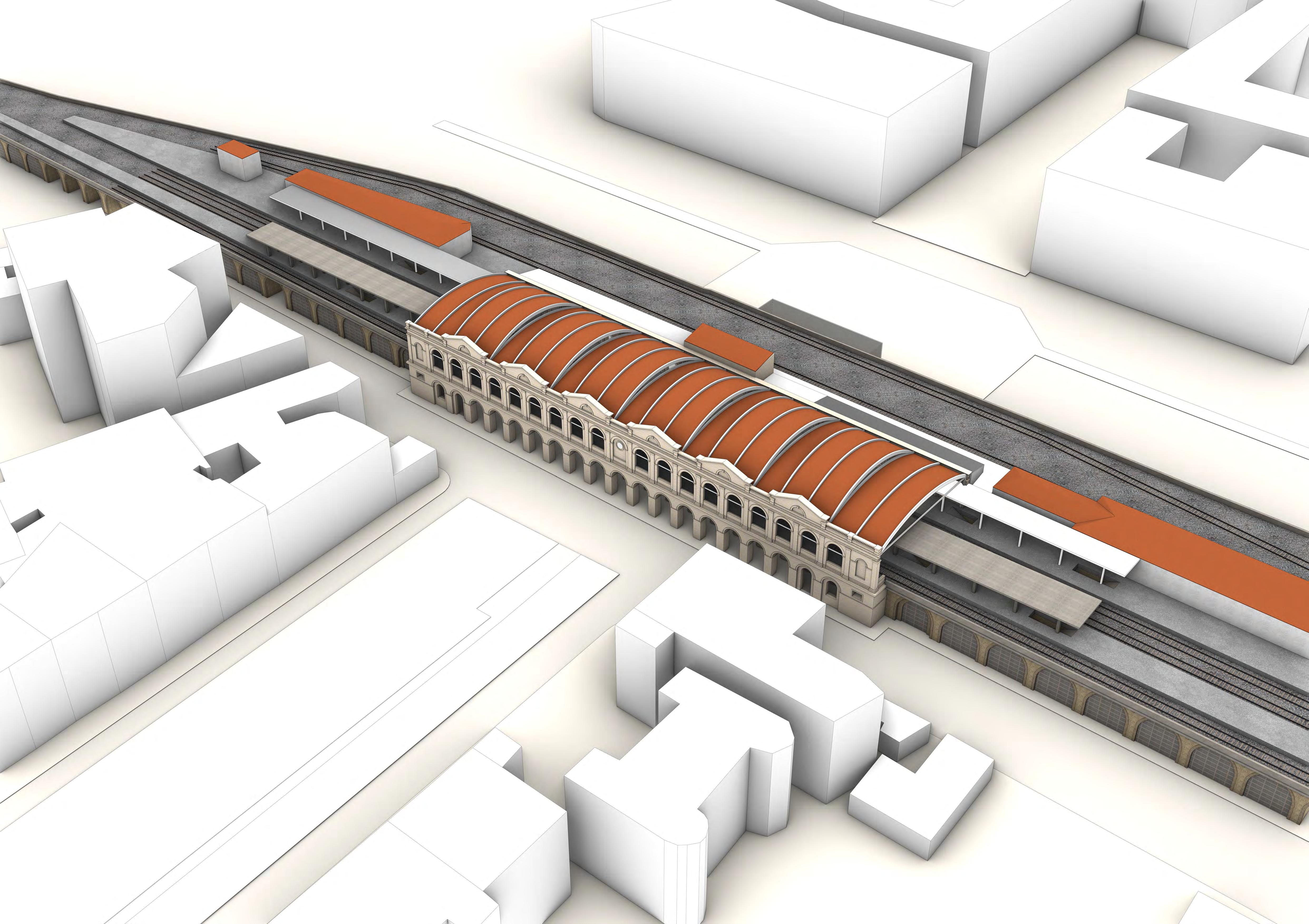
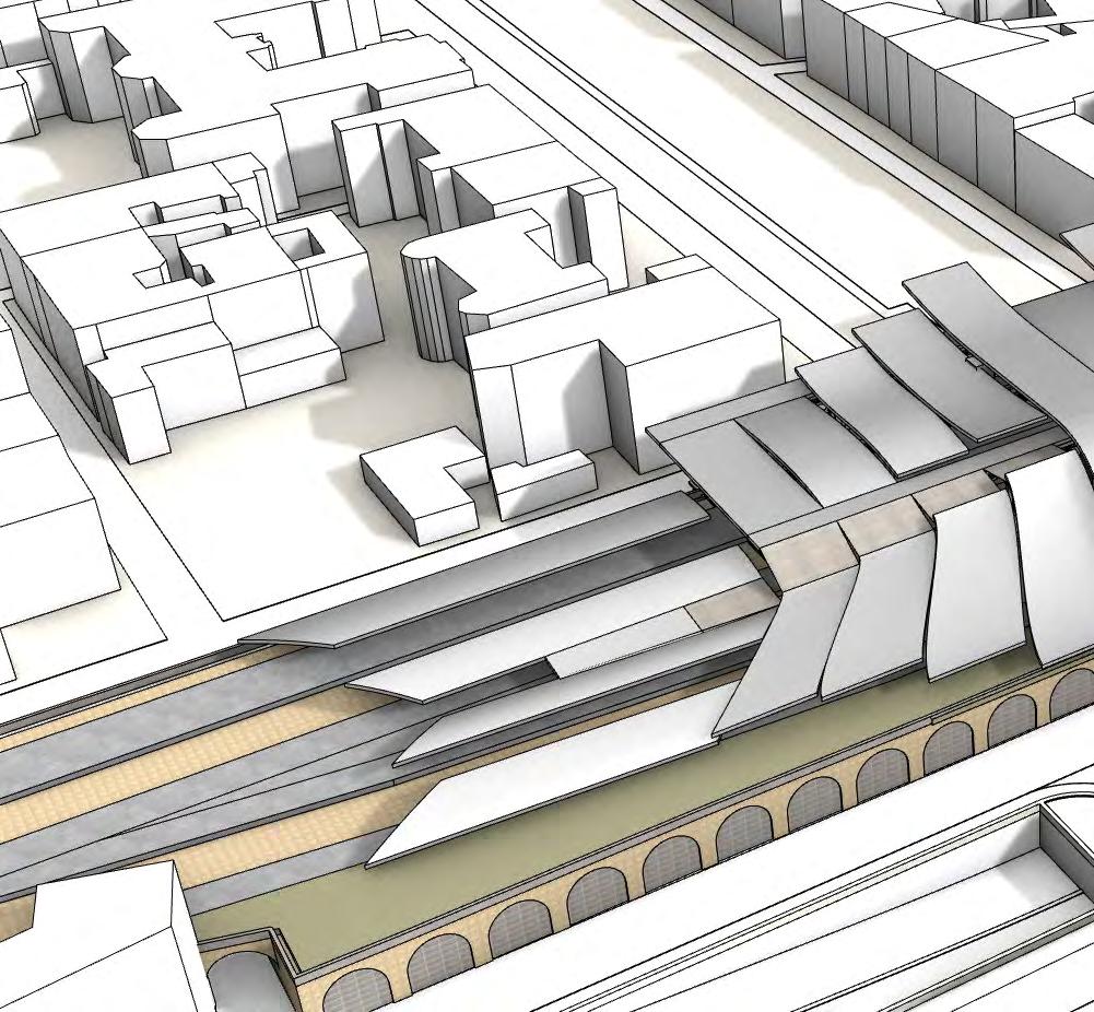
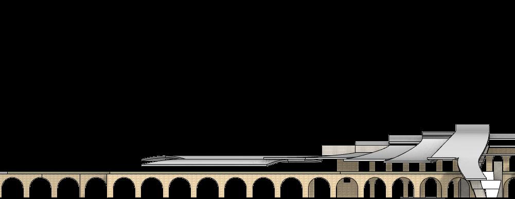
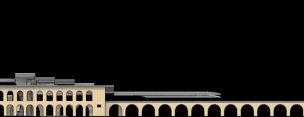
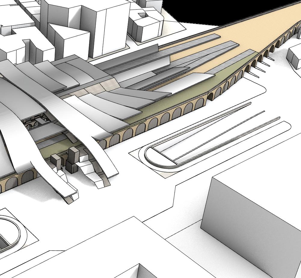
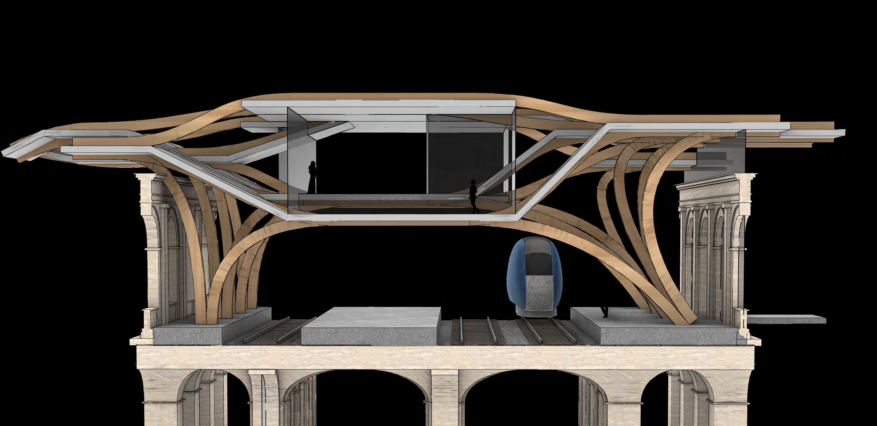
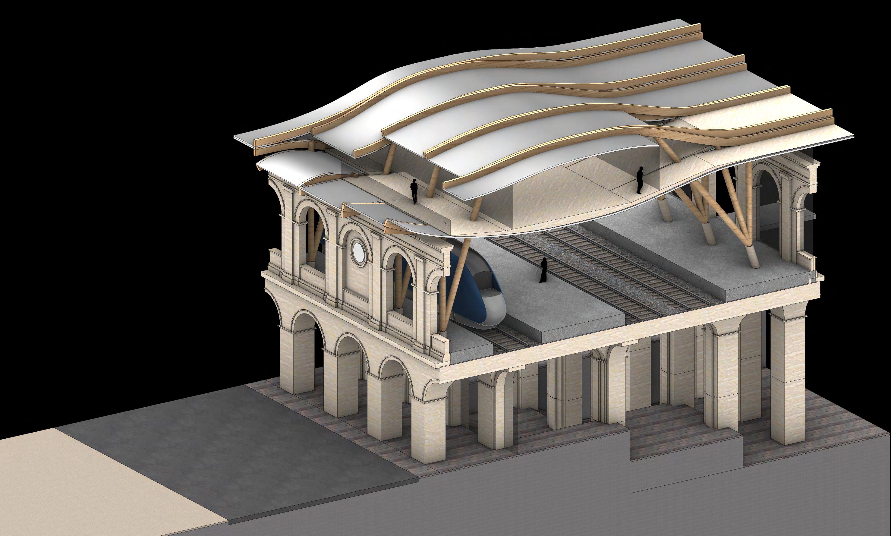
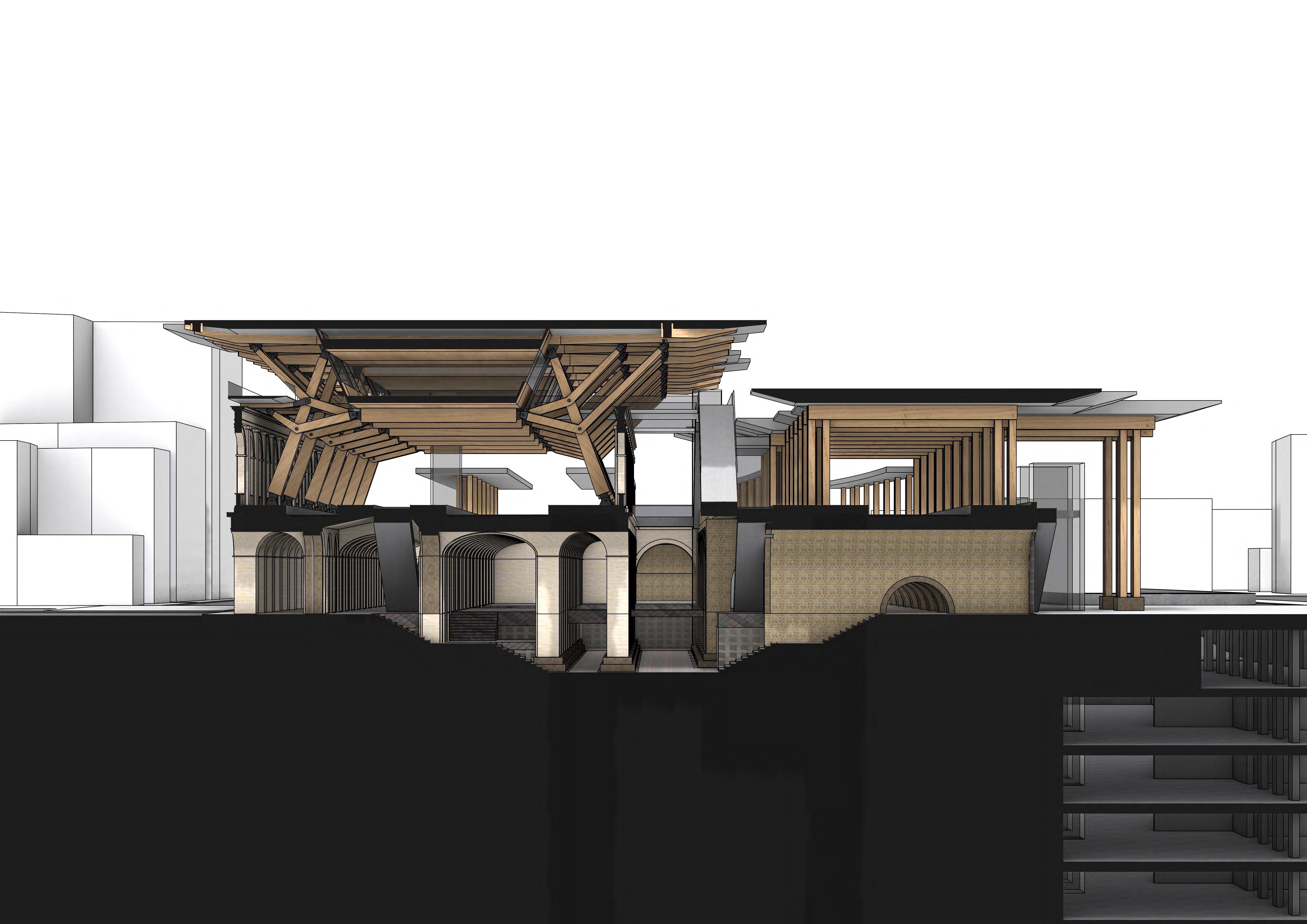
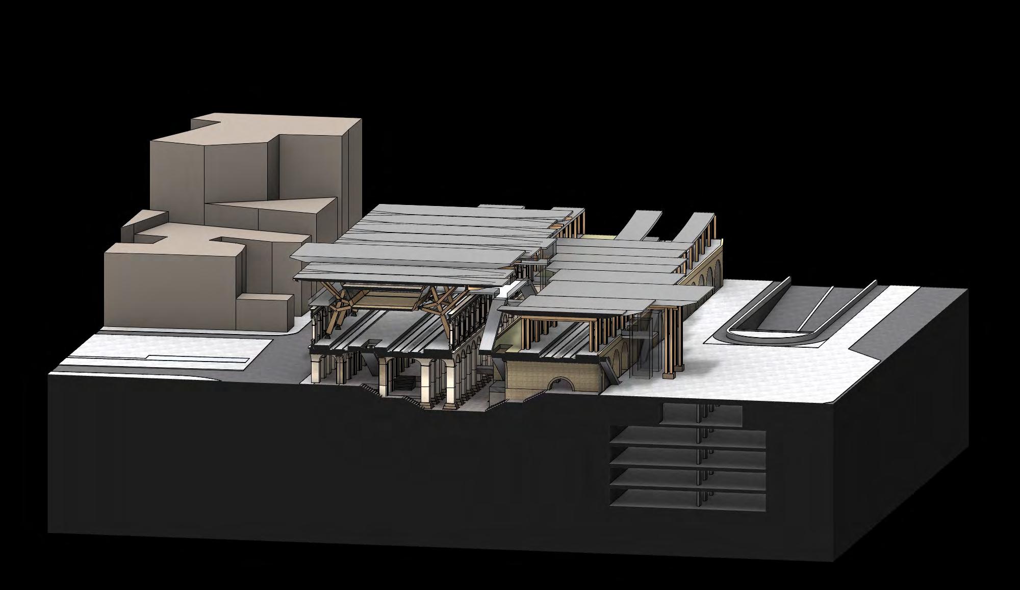
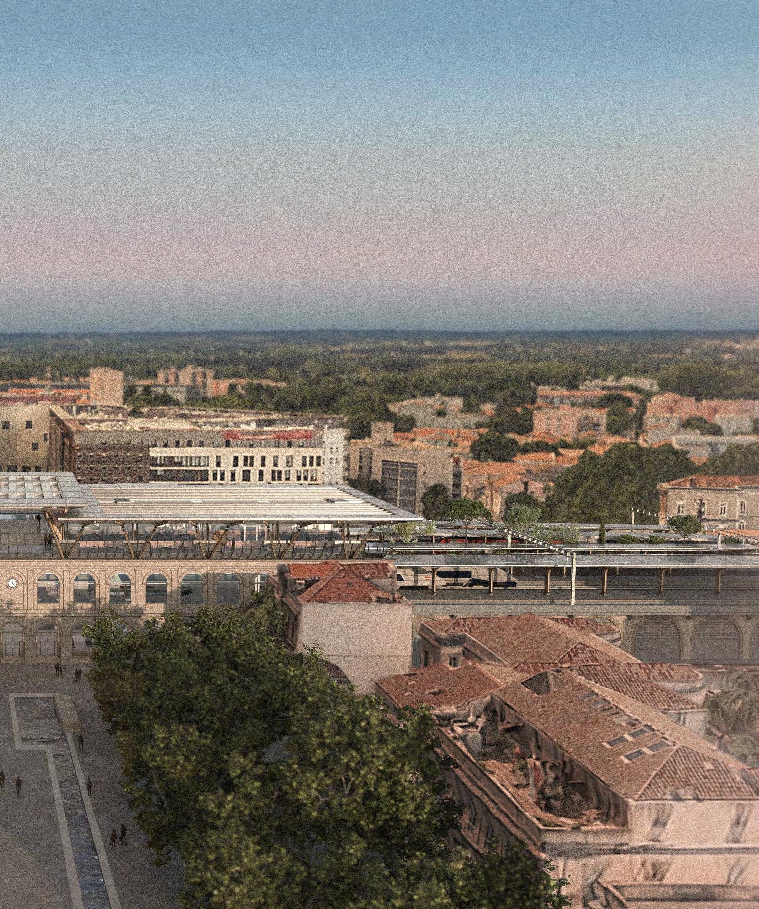
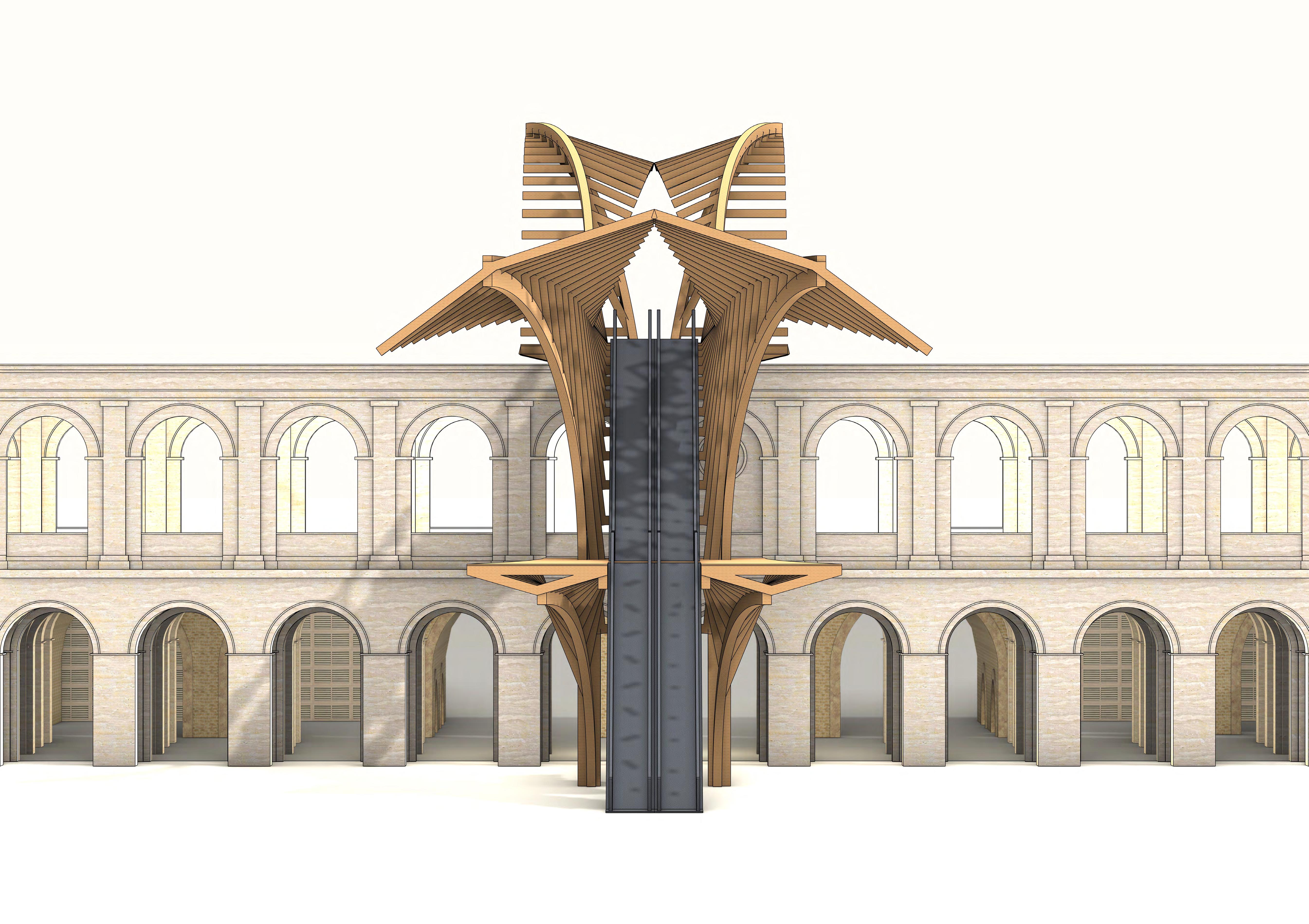
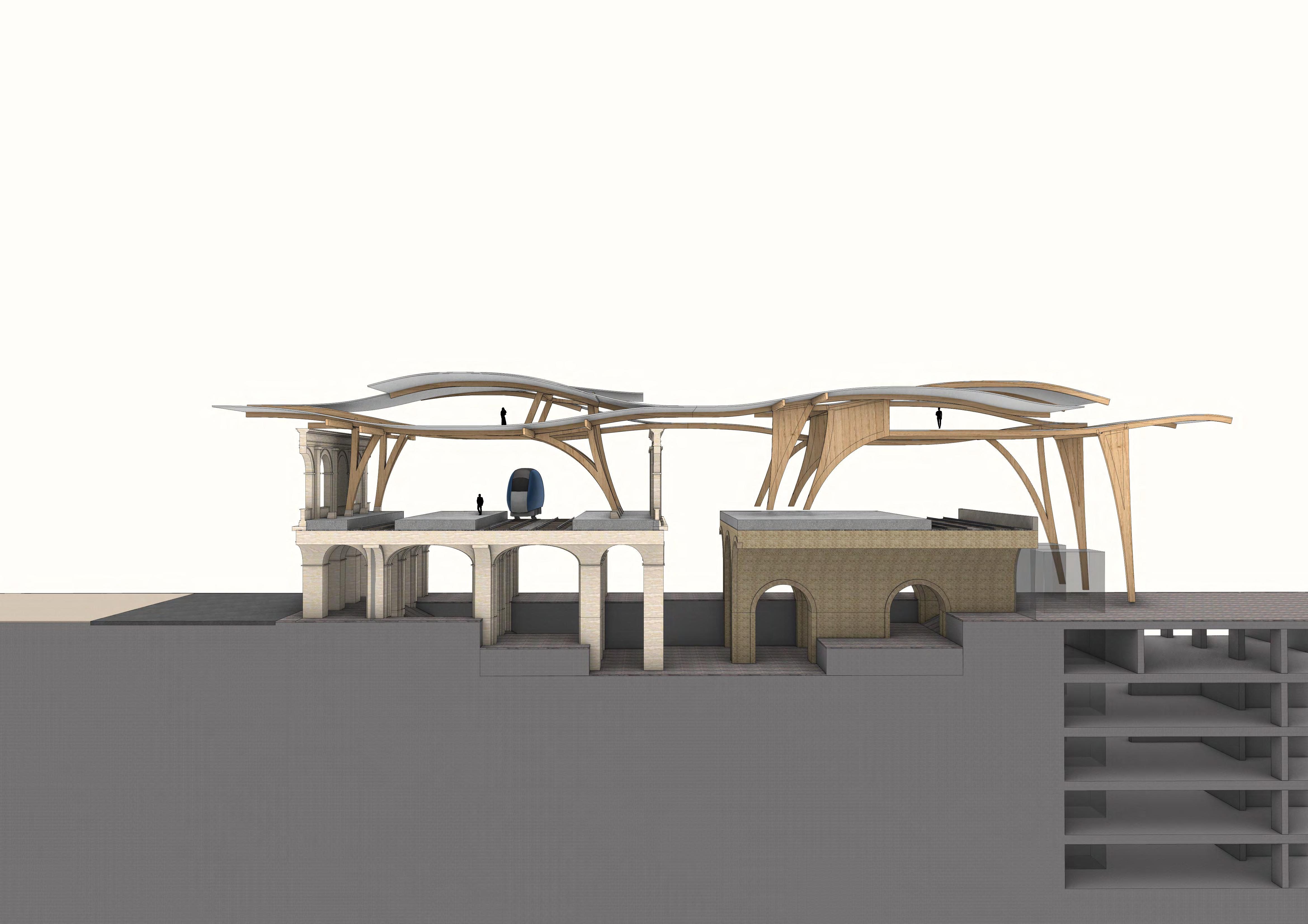
The project presents a new approach to the retrofit of existing train stations, diversifying their programs while integrating the new interventions with sensitivity to the existing architecture. It focuses on the retrofit of a 19th century train station in Nîmes (France), situated on an international high speed rail corridor. It aims at reactivating the train station with restaurants, retail and gardens, while also improving accessibility within and connectivity between each side of the station.
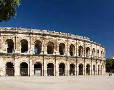
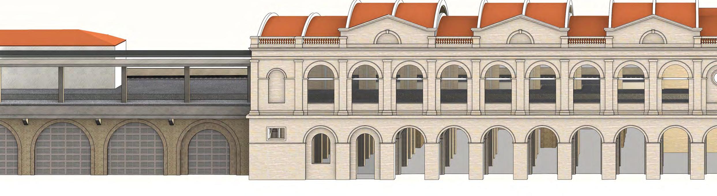
The station serves as the gateway to the city and is redesigned embody the local Mediterranean lifestyle and the rich Roman heritage that inspired the city’s architecture. The existing station consists of a stone viaduct with arched façades, similar to the Roman Arenas at the other end of the avenue.
The new intervention adapts to the existing façades and has a low impact on the urban fabric, respecting the traditional architecture of the city while improving the experience of the train station and expanding its program to better serve the neighborhood.
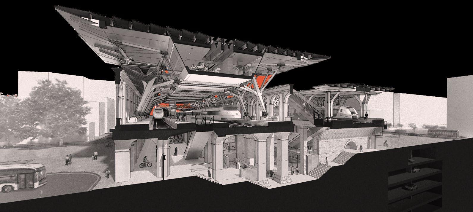
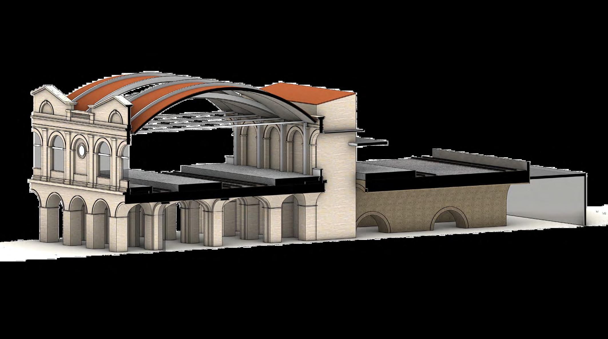
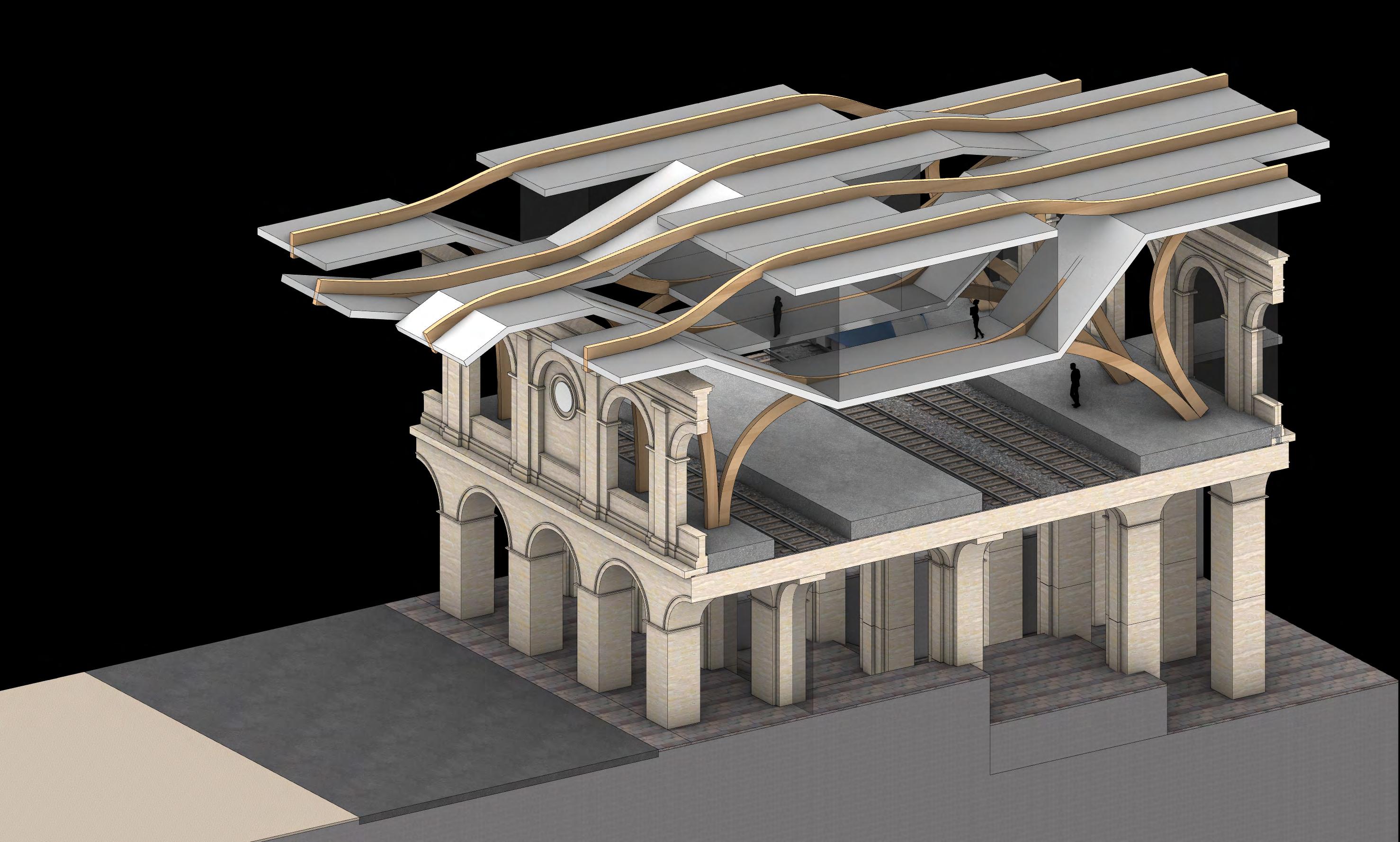
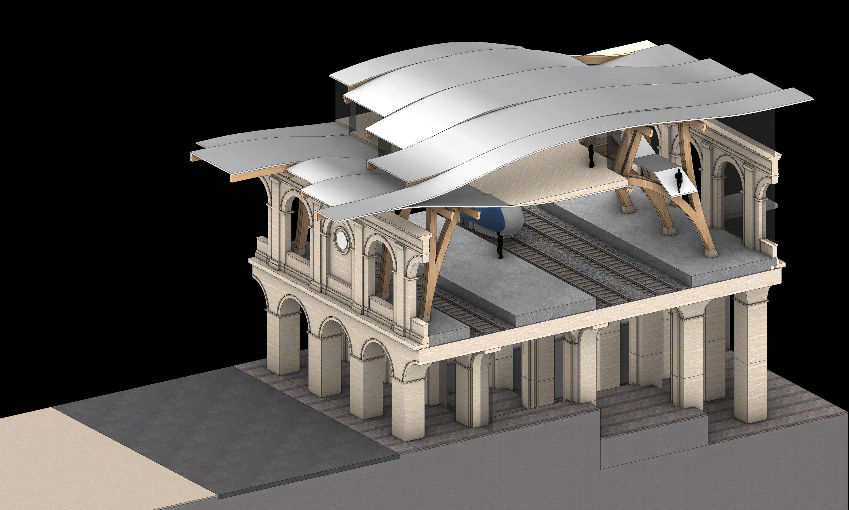
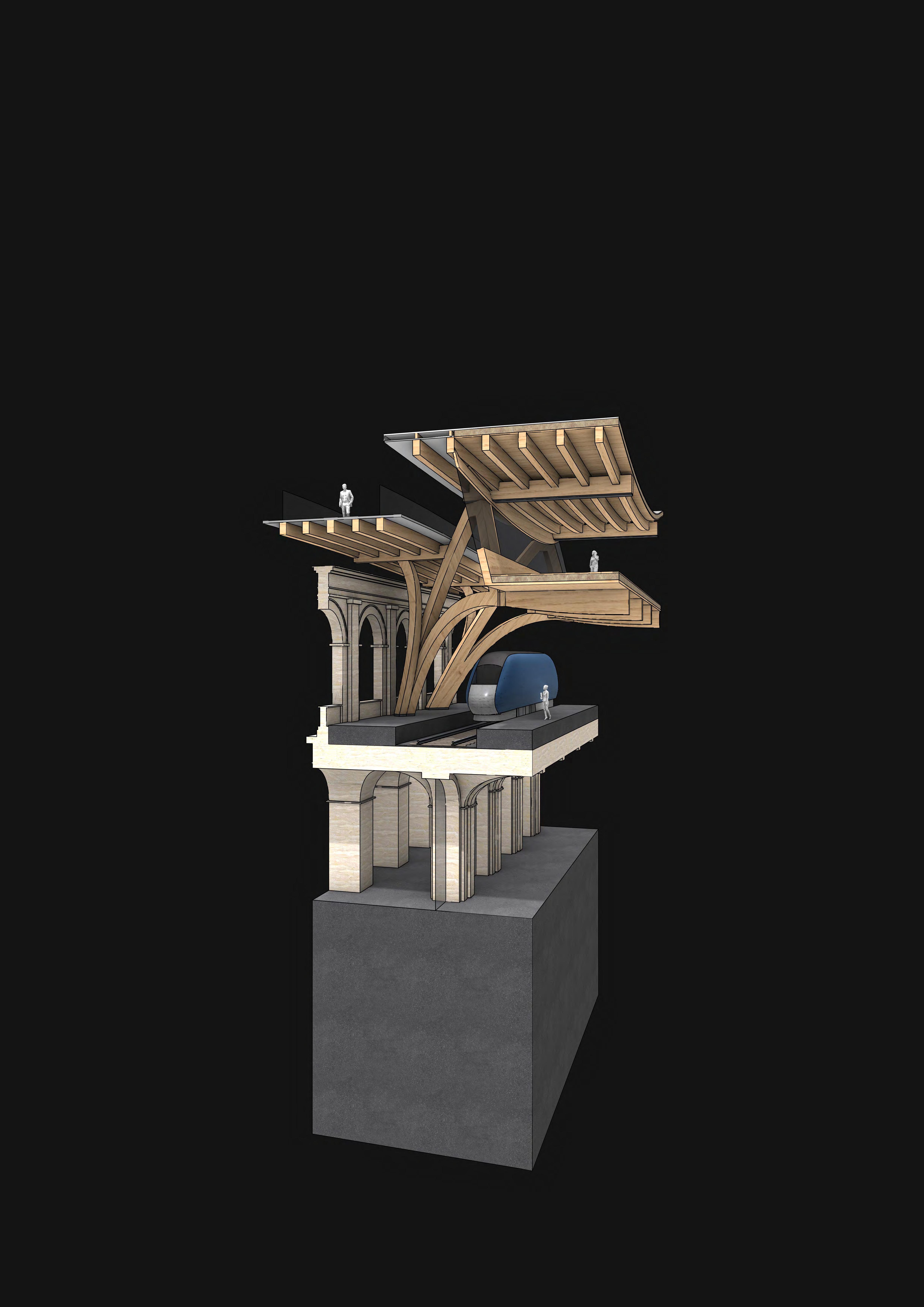
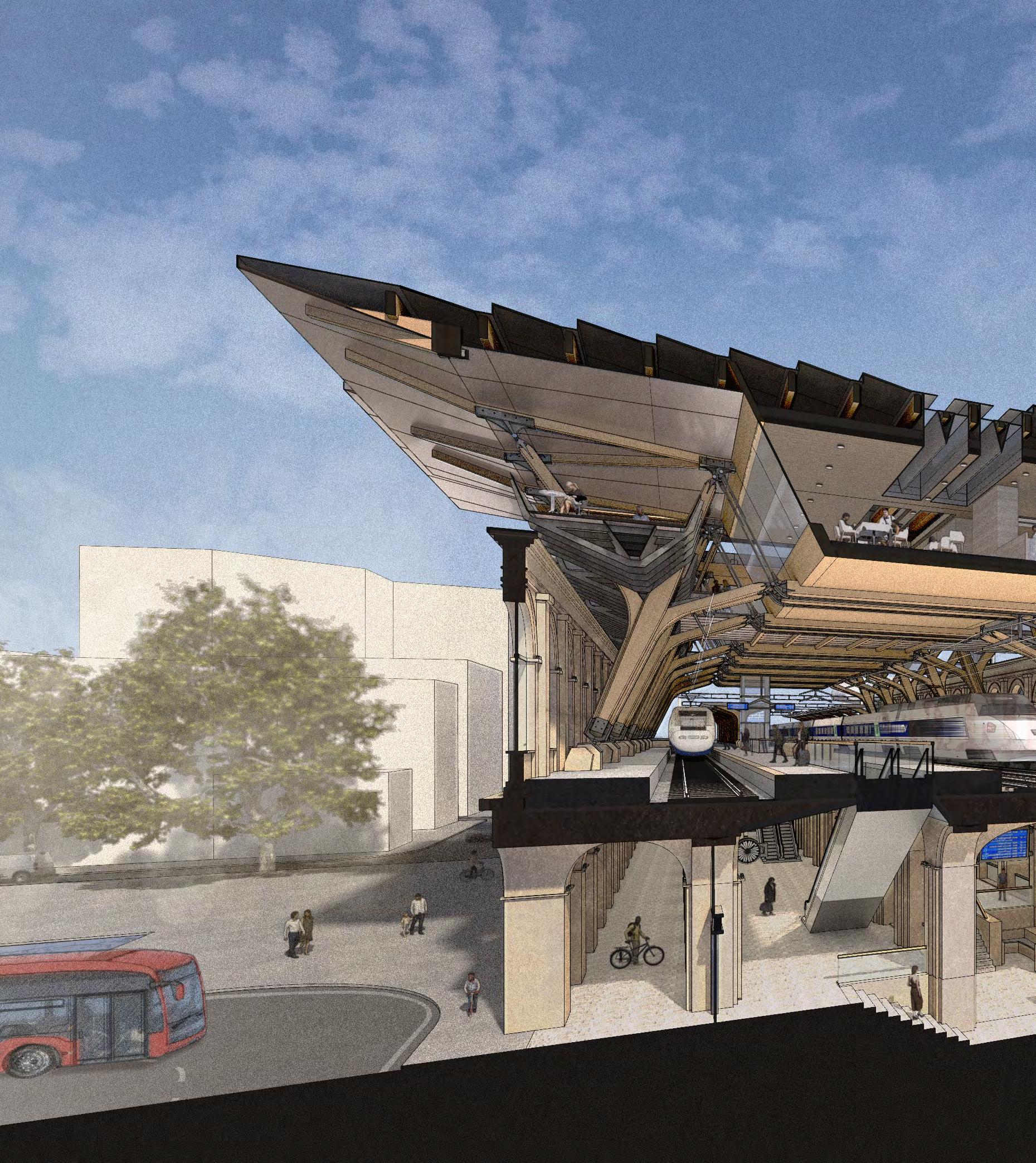
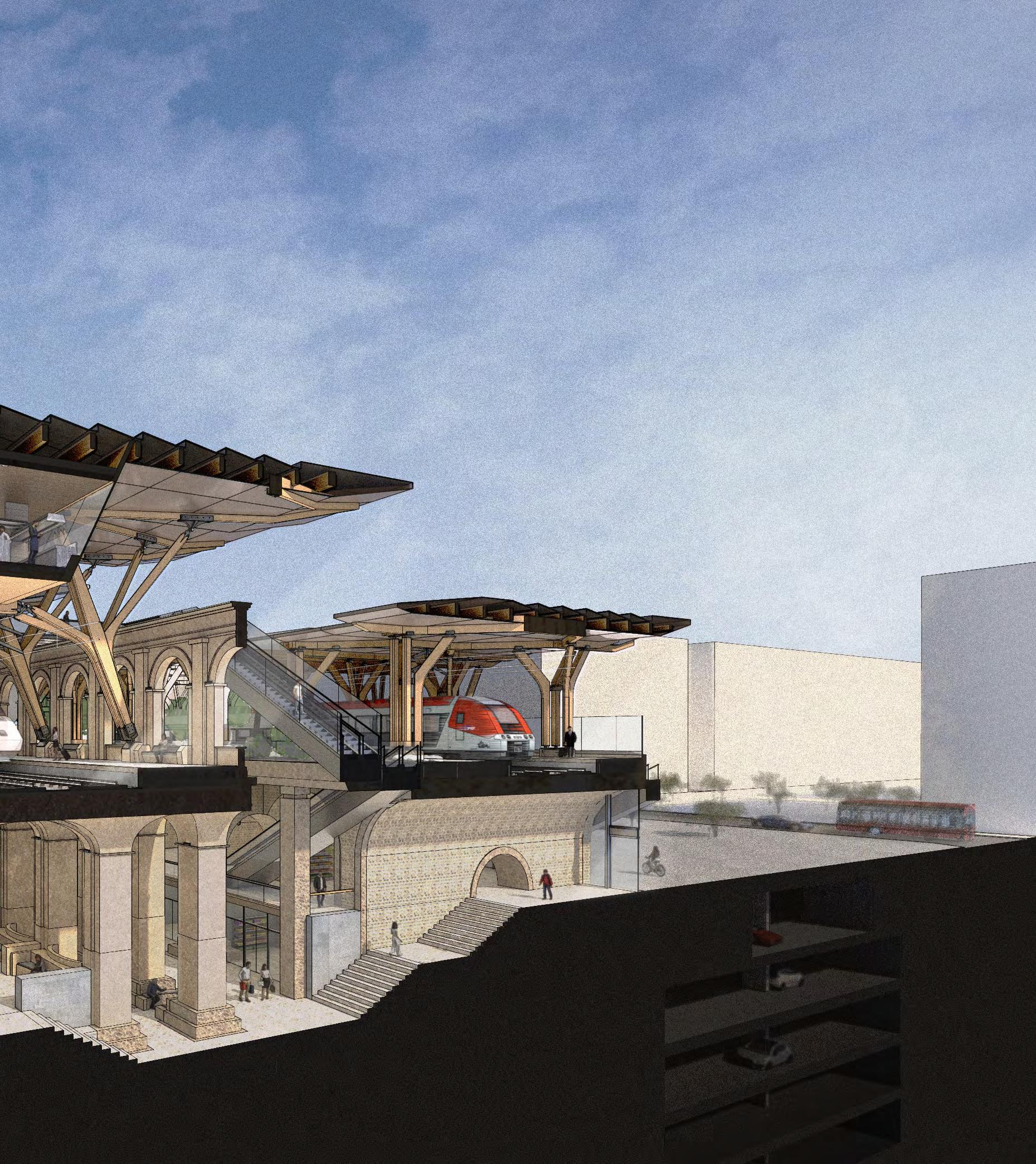
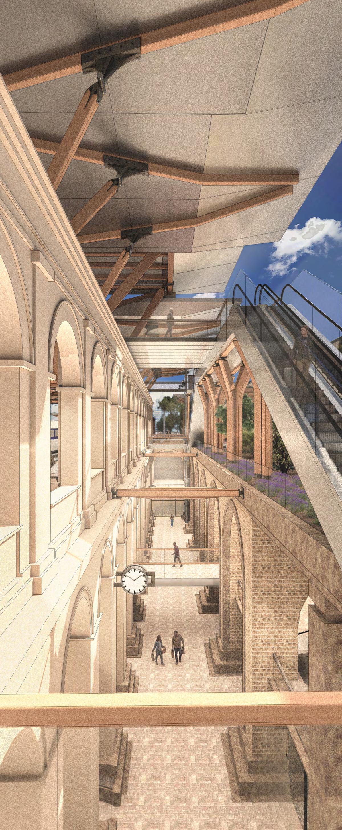
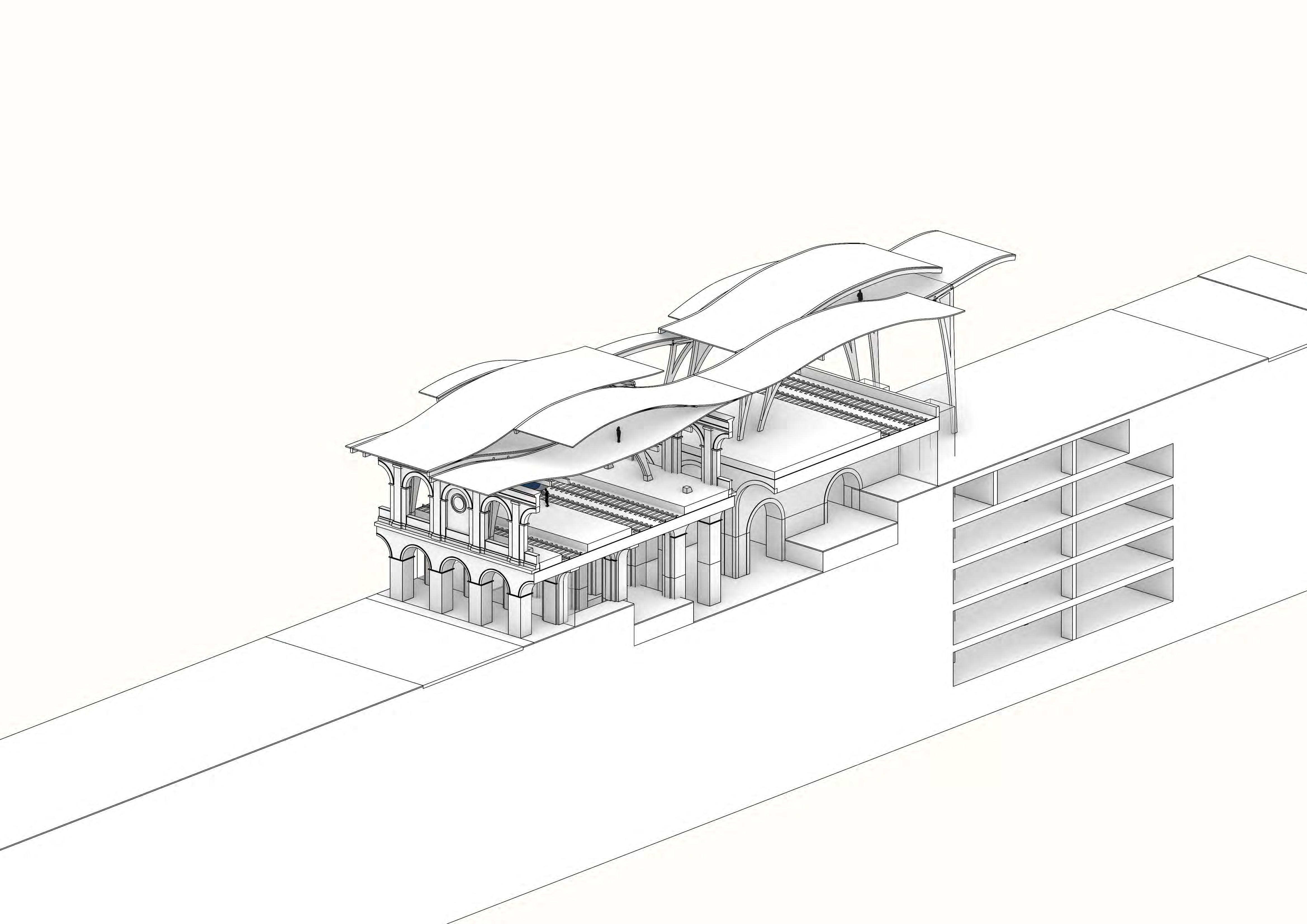
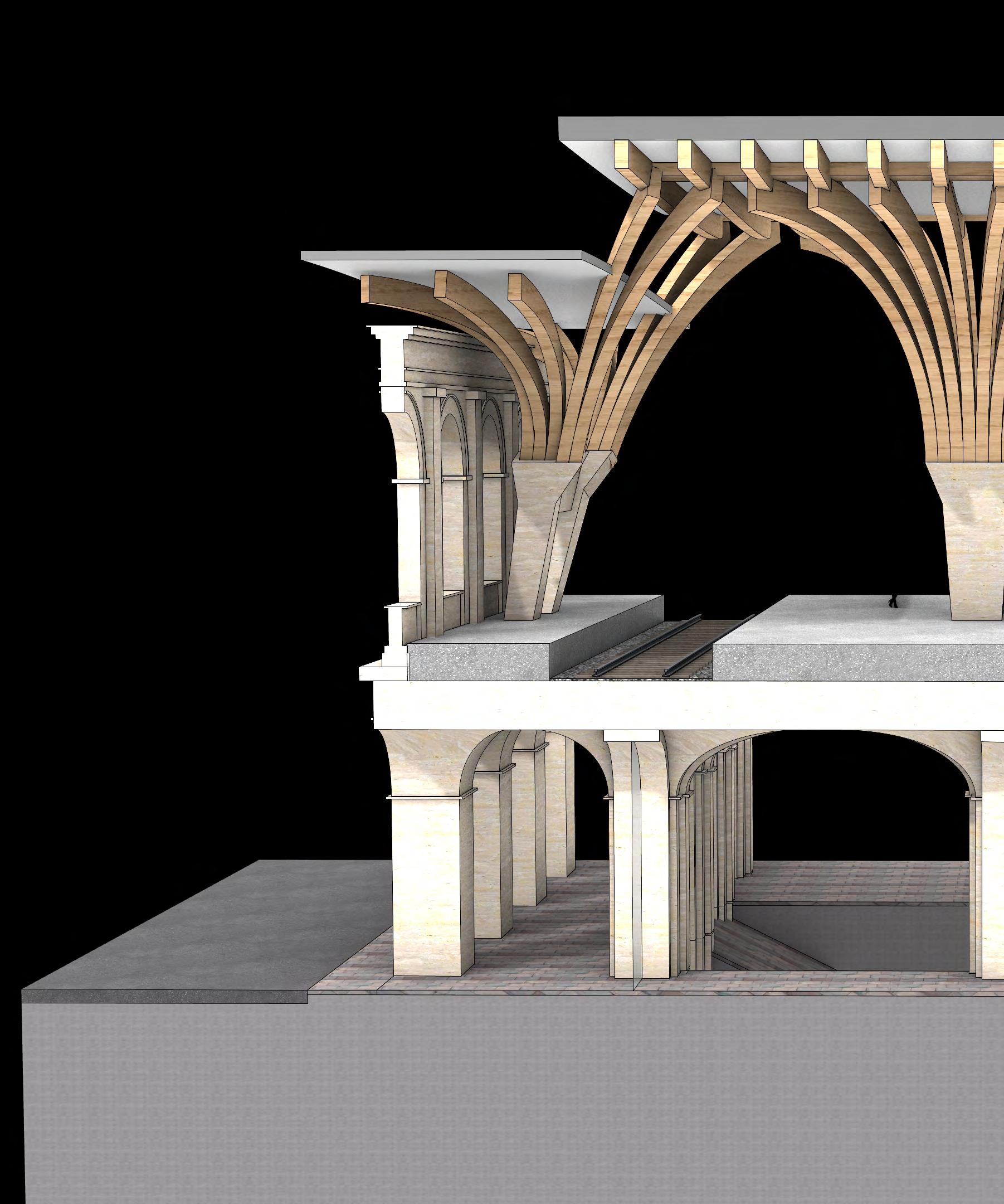
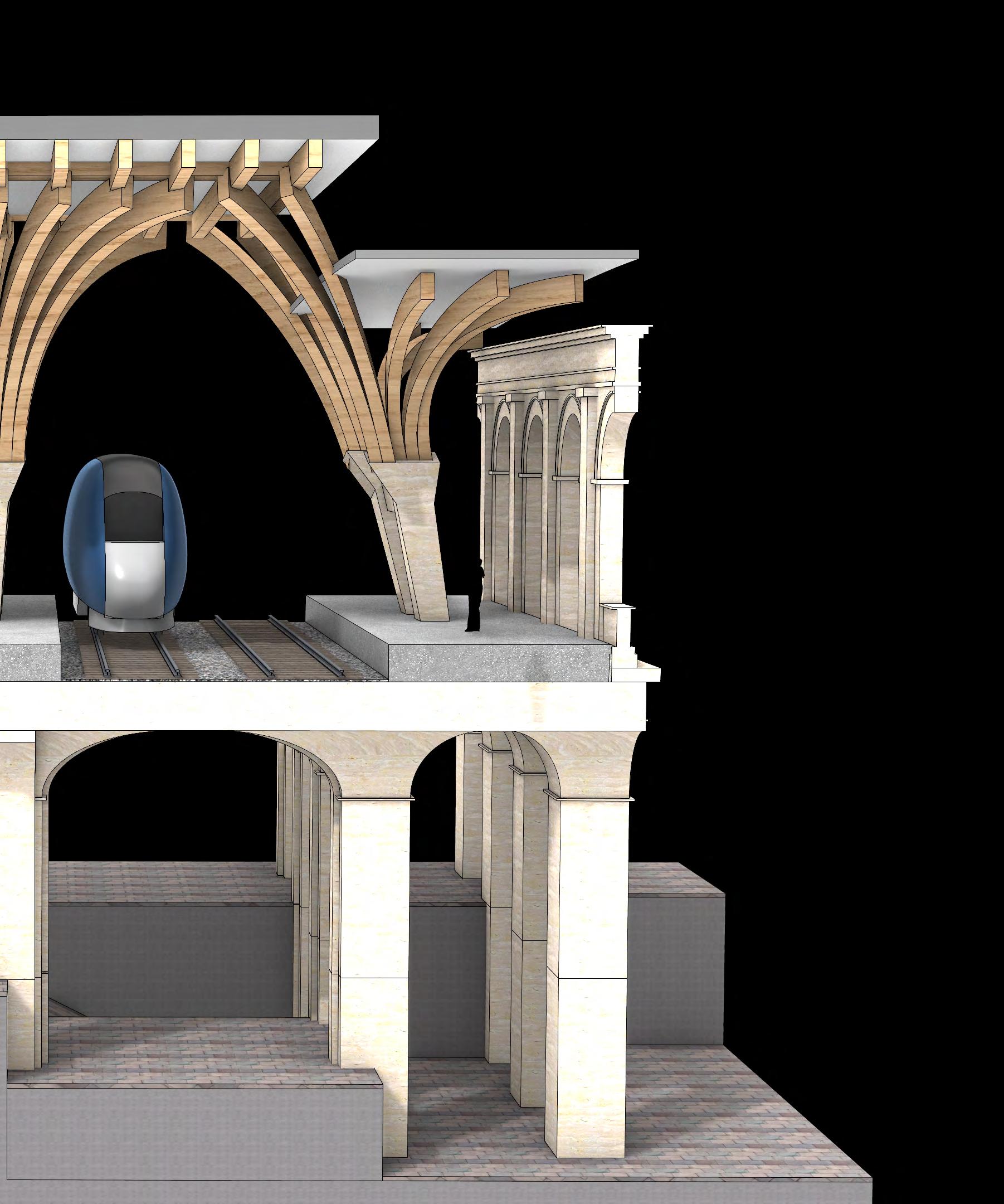
The new structure projects this design language higher, without overwhelming the historic station. The roof spans over the viaduct, establishing the station’s footprint and tying all the spaces together. It is supported by a glulam structure, with nested restaurant mezzanines and terraces above the tracks. The platforms are rearranged to insert a garden in the middle, bringing a more peaceful atmosphere into the bustling environment. The ground floor is excavated down for a retail gallery, opening up to a central atrium connecting all levels and implementing daylighting and passive cooling strategies.
Nîmes, France
attic structures investigation
Investigating spatial and structural tectonics in the context of infrastructure architecture.
Paddington station, london - BRUNEL
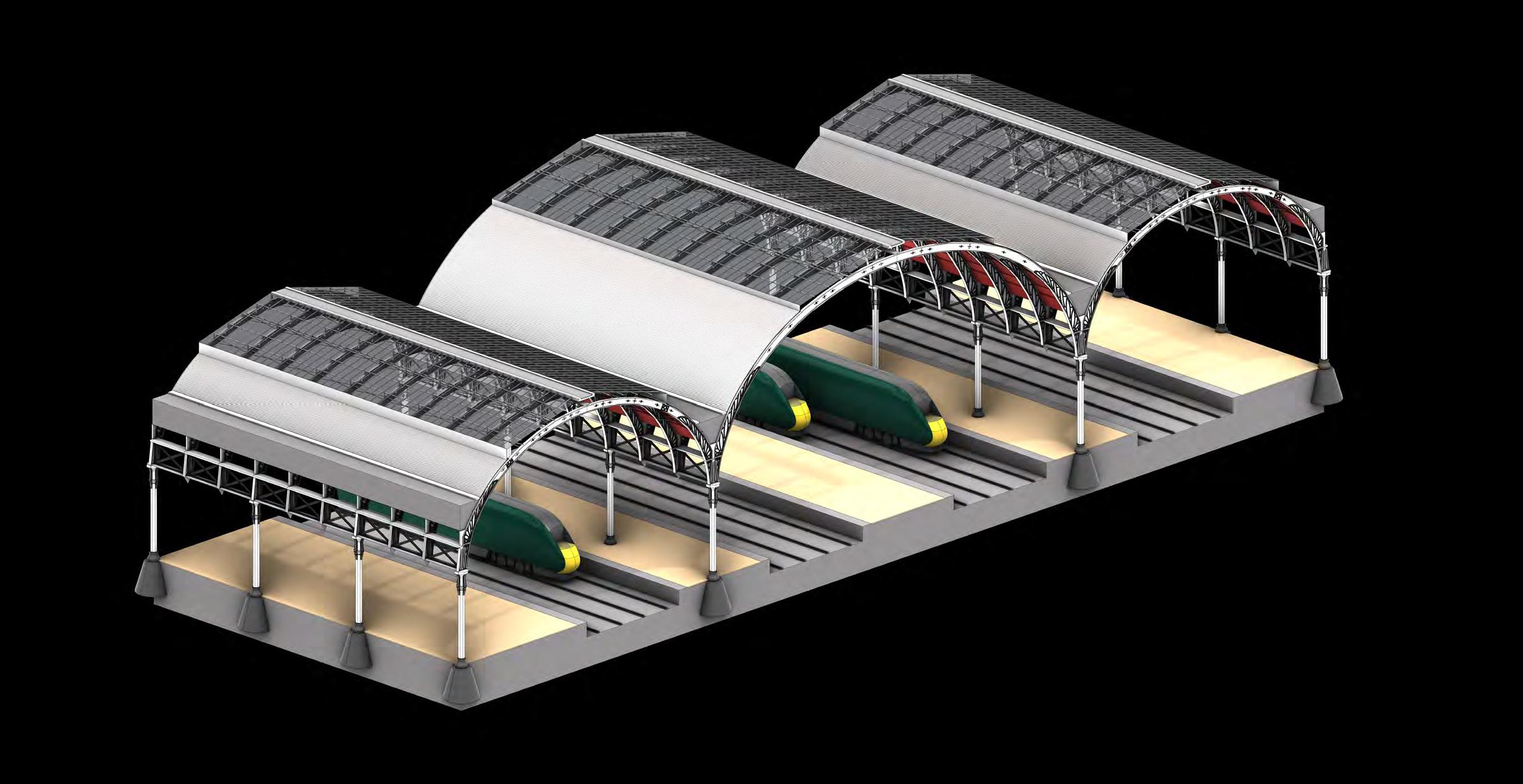
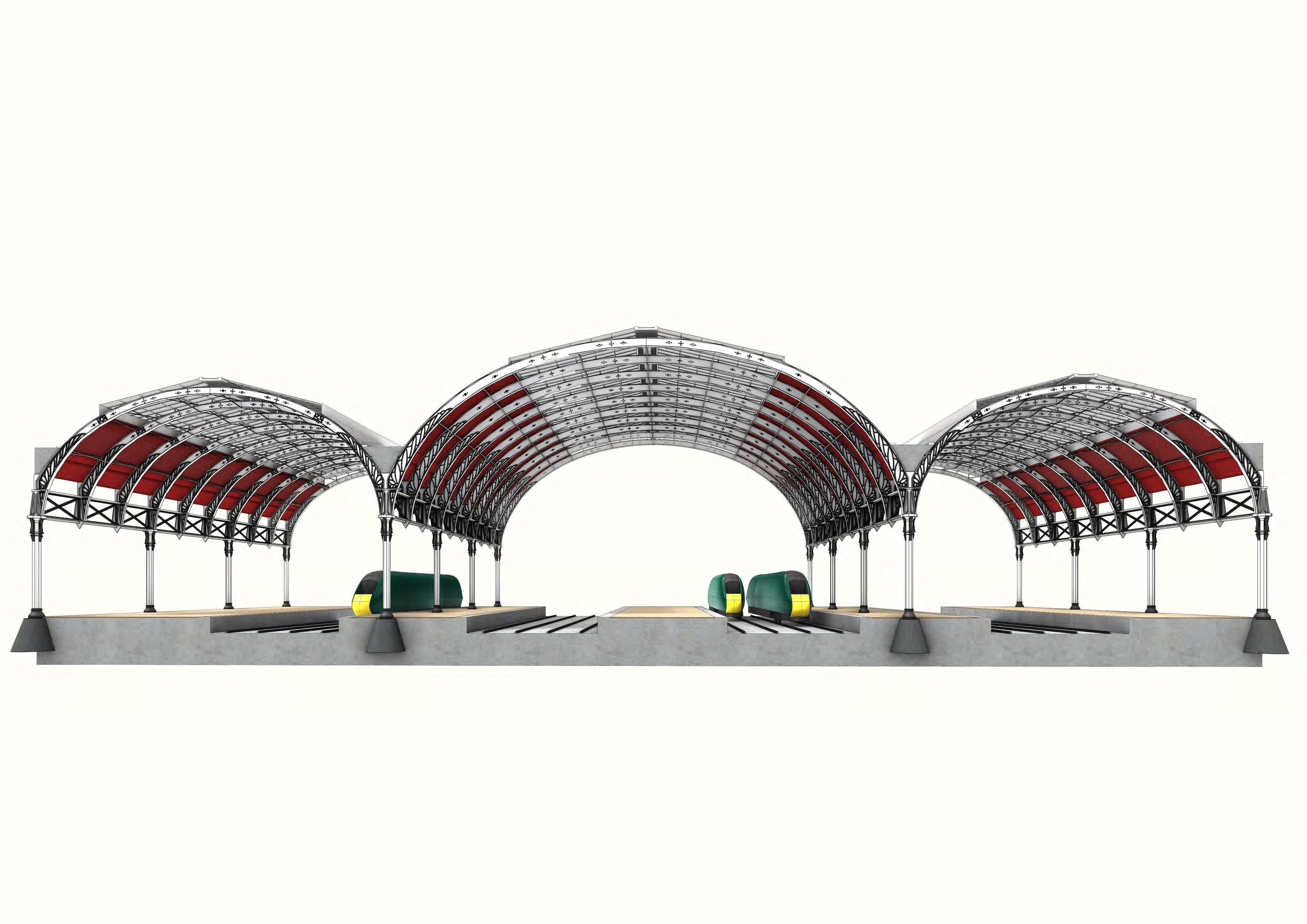
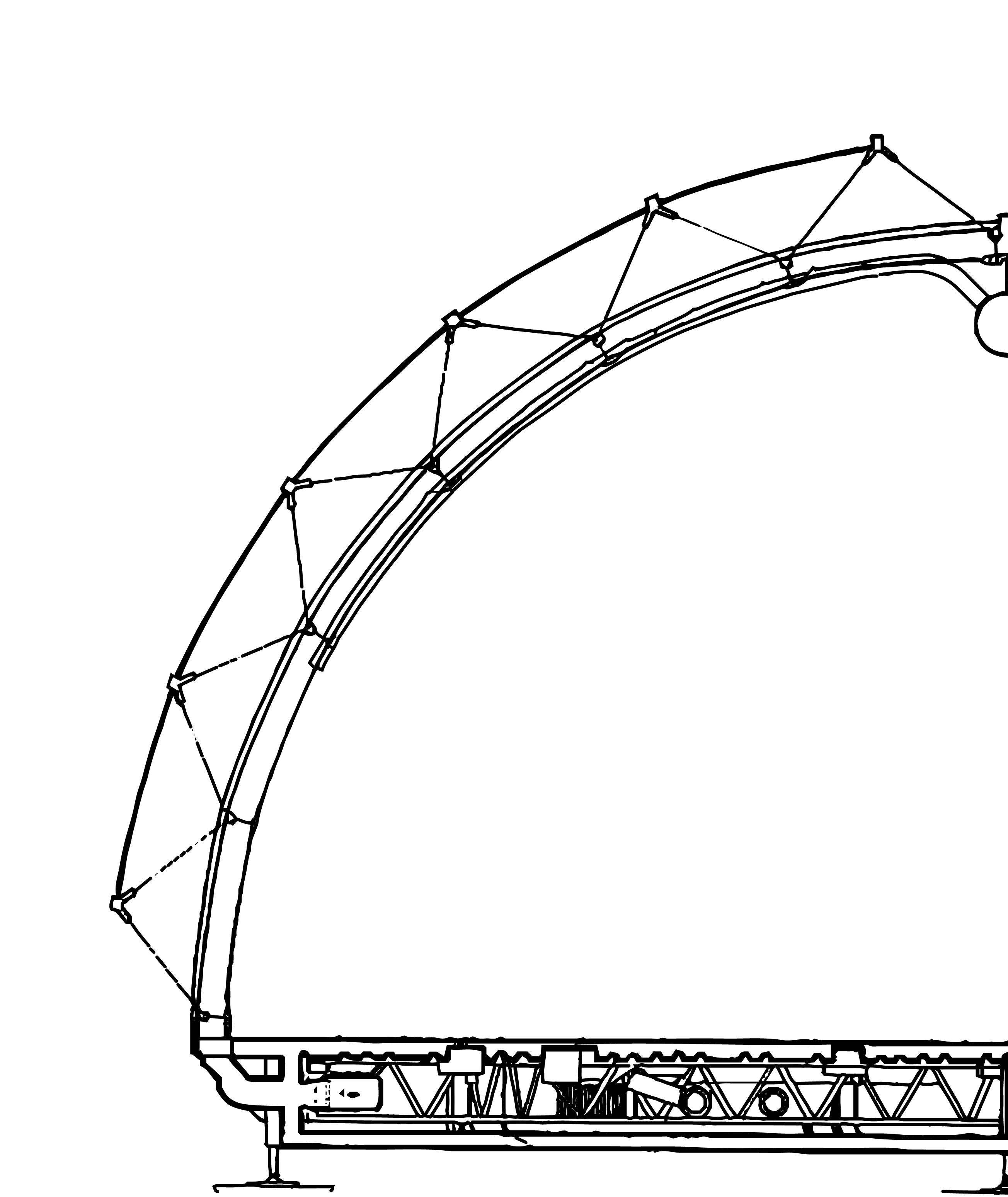
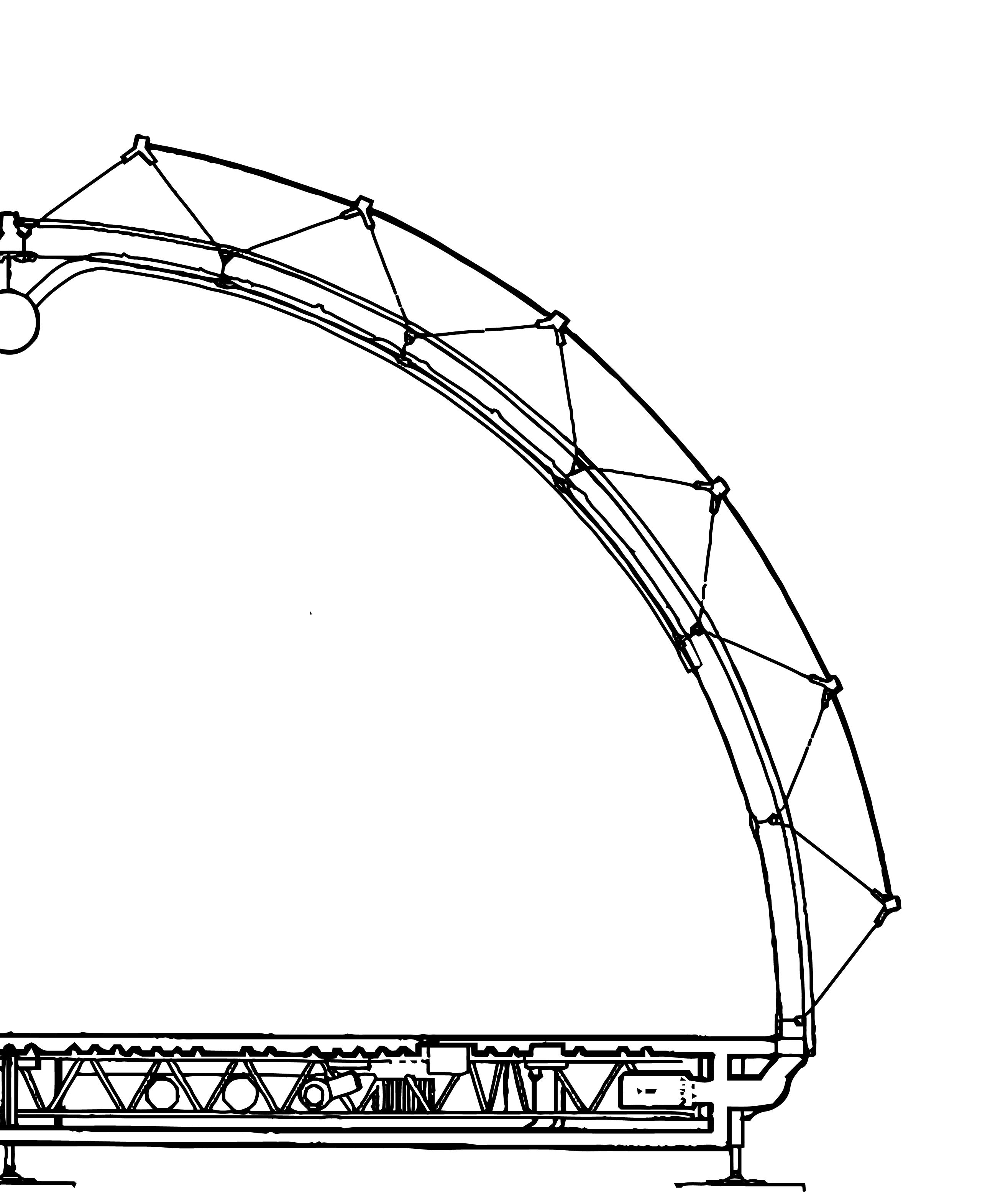
Built in 1854, Paddington presents a modular system of wrought iron columns and arches to form sheds parralel to the train tracks. The sheds open up at the top with large windows, showering the station with light. The arches express a contrast in density from the imposing trusses that supports them, to the wide windows. They are reinforced at the base with leaf-like ornaments and perforated at the top with geometric shapes, thus optimising strength and lightness.
Isometric section of the three original sheds Columns are placed every set of three arches. The arches are integrated in trusses with cross beams to hold the two middle arches. The columns rest on pad foundations. The lightweight arches and the strong trusses allow for fewer columns, freeing the platforms from bulky structures.
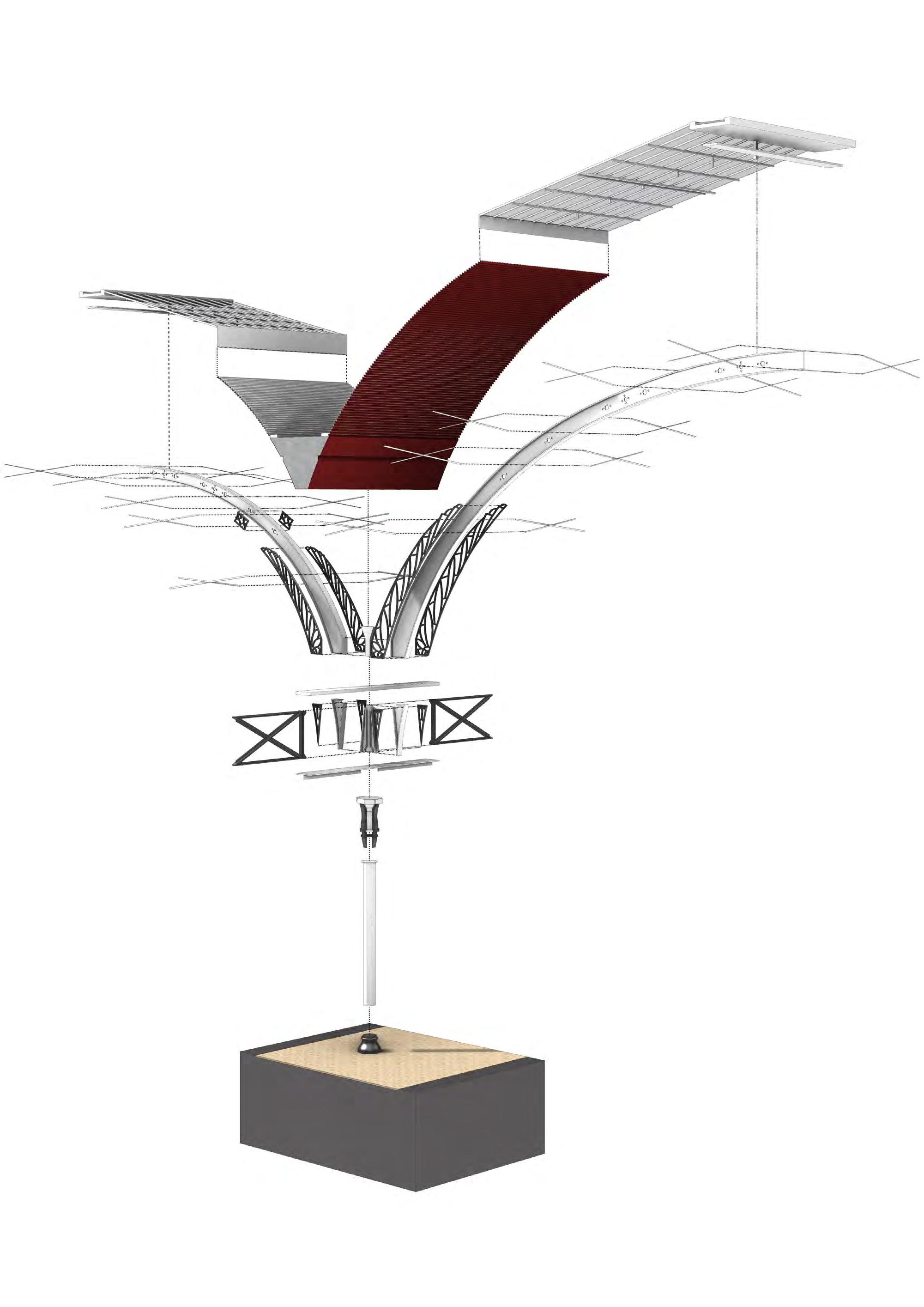
Column and arch detail
The column capitals are adorned with black accents that recall classical architecture. The arch reinforcements represent leaves reaching out for light, leading the eye to the windows.
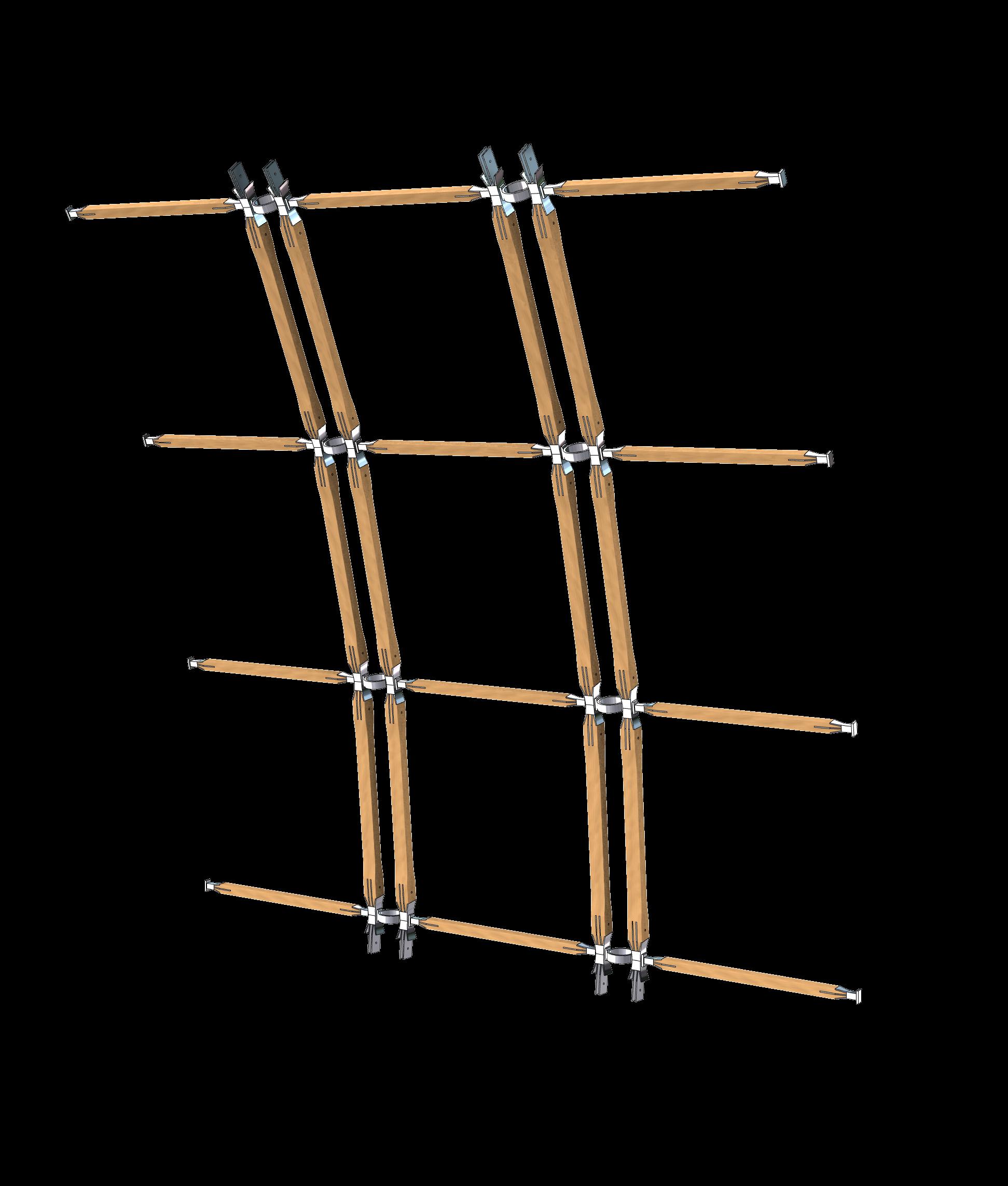
Module assembly diagram
The wrought iron elements are connected with rivets accross the length of the contact edges.
Structure Hierarchy
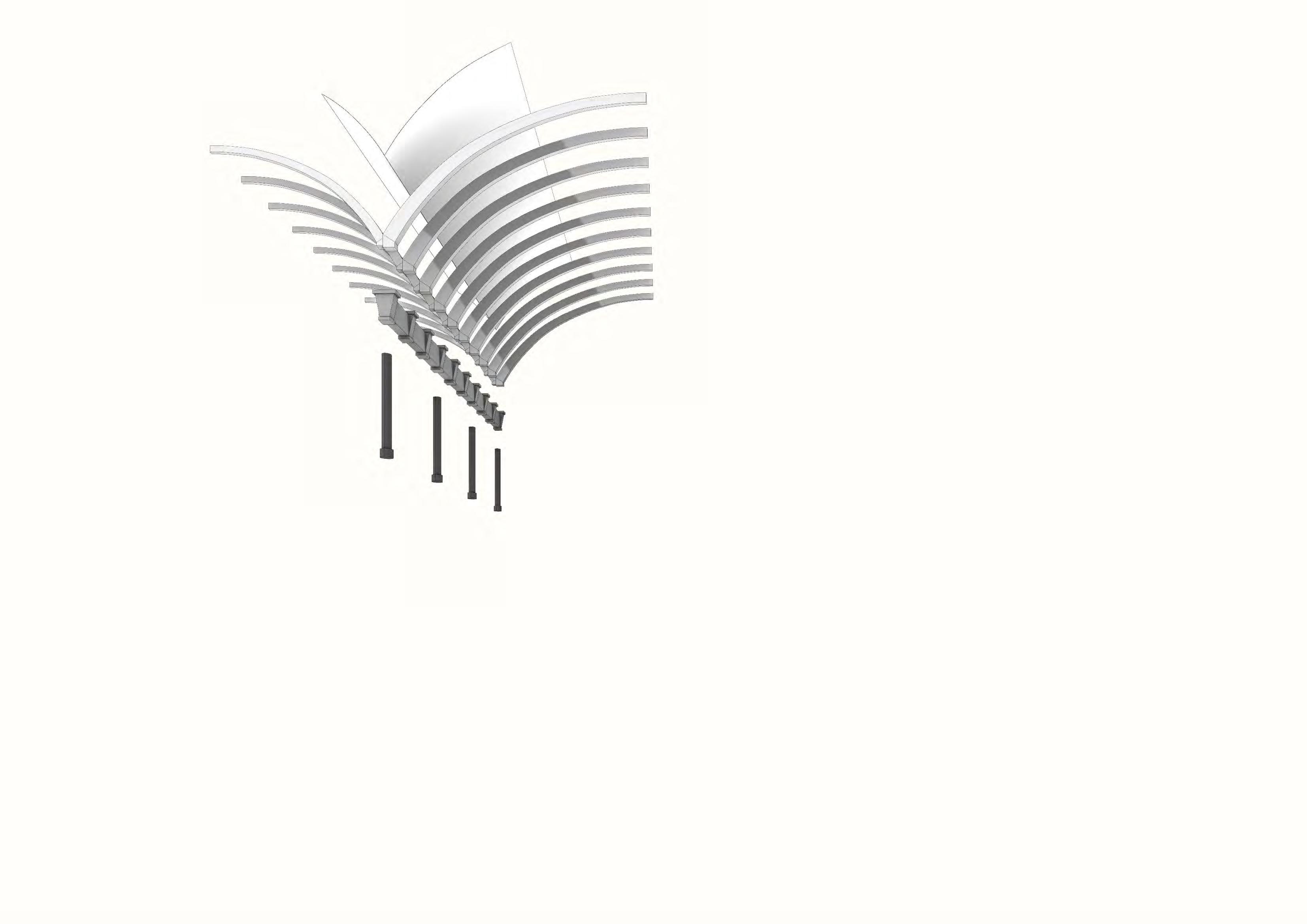
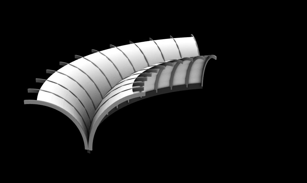
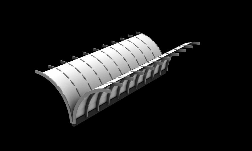
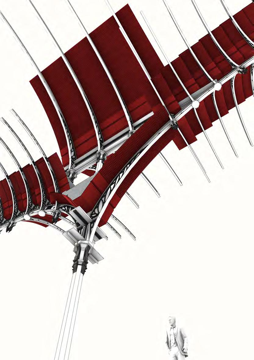
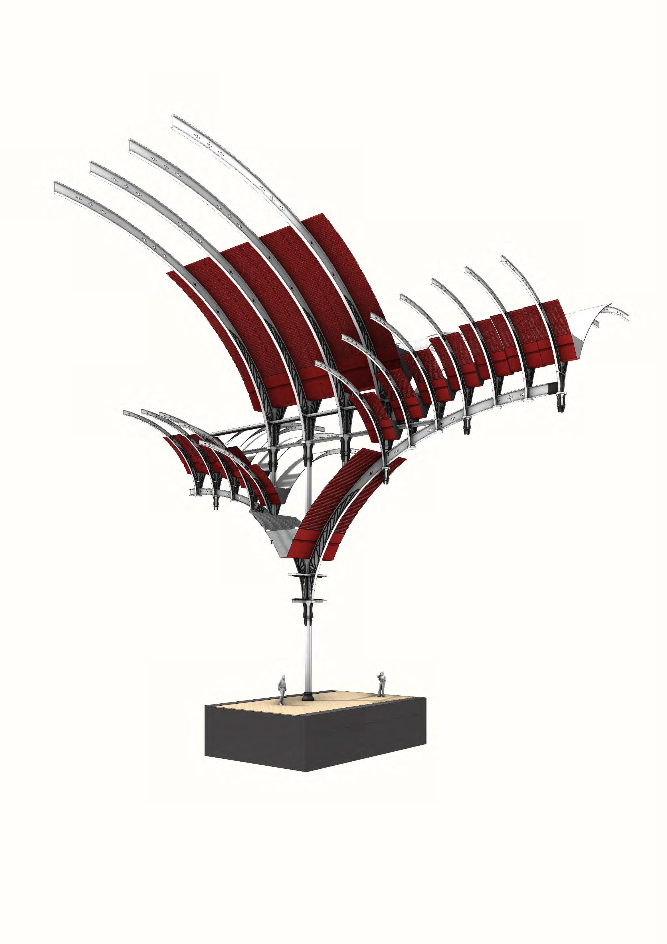
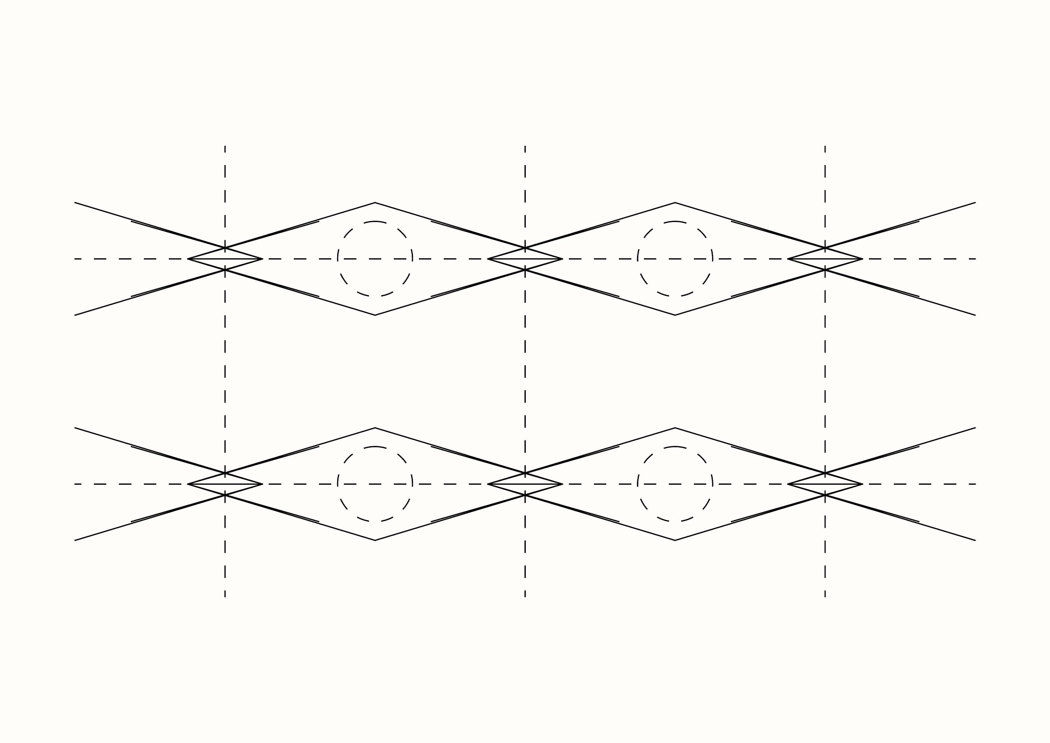
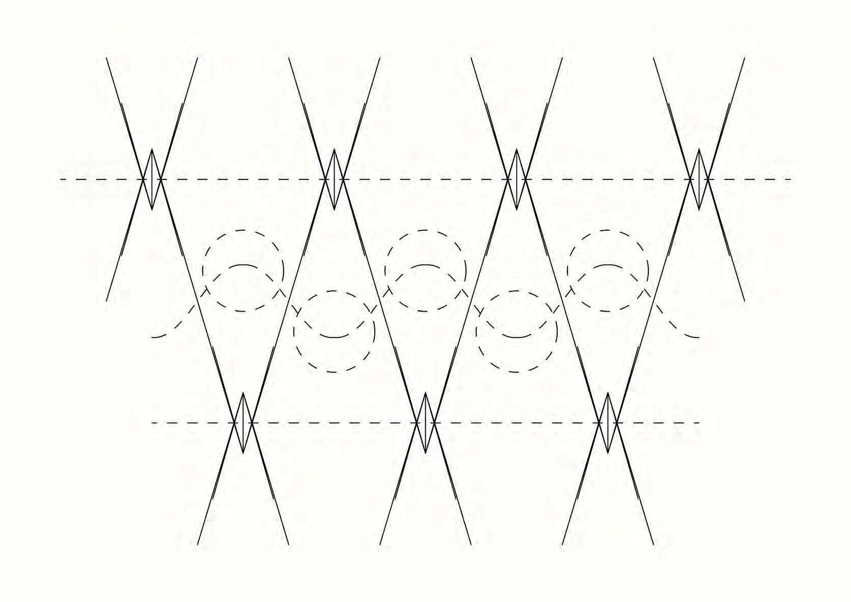
The vault system can be rationalised into a primary truss with secondary rib arches. The latter is anchored on the linear truss and expands into a curved vault. Therefore, the primary truss dictates the orientation of the vault. Altering the linear guide truss into curved geometries would propose new double curvature geometries for vaults.
Structure Composition
–Secondary ribs –Primary truss –Support columns
Perspective Section
A portion of the three original sheds are represented over 3 segments.
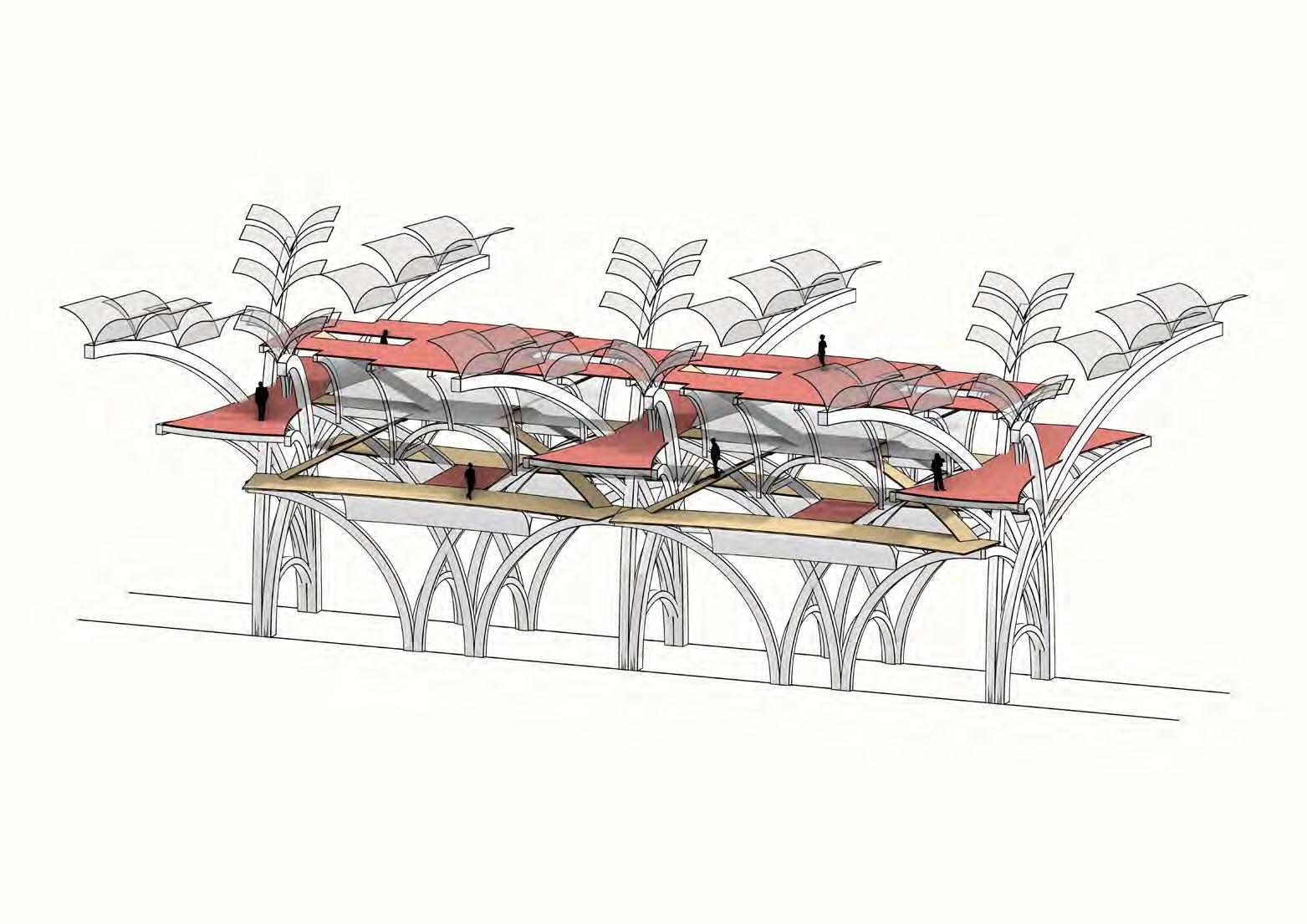
Twisting Iterations
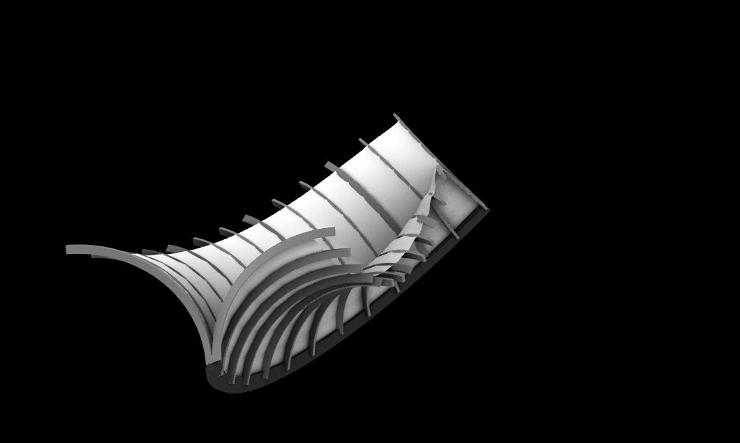
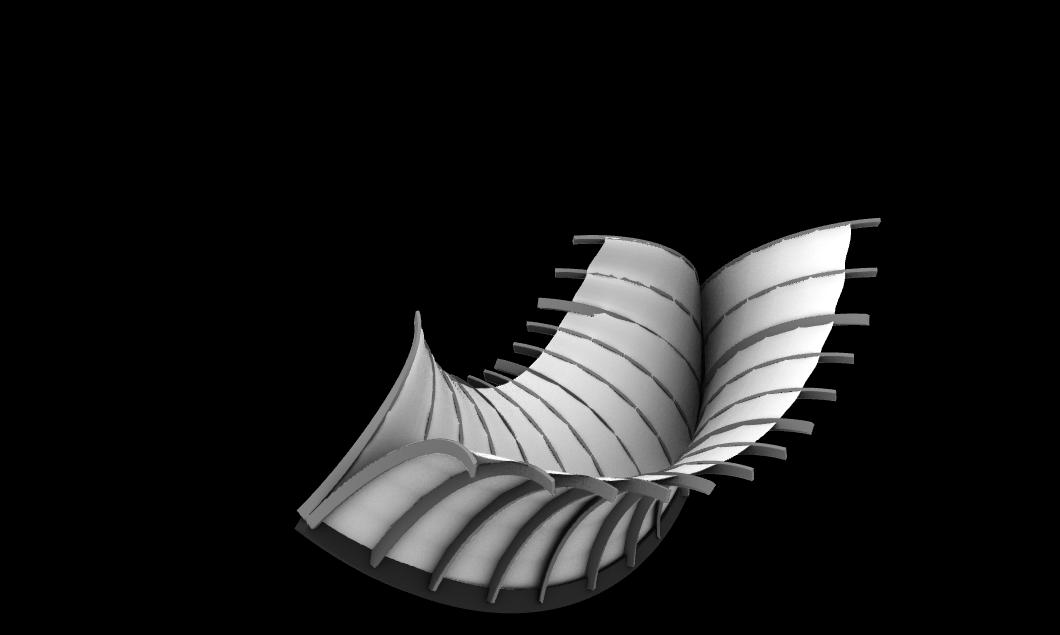
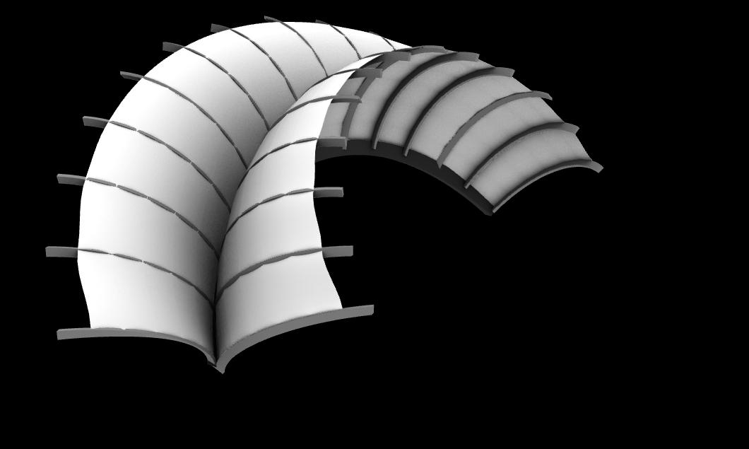
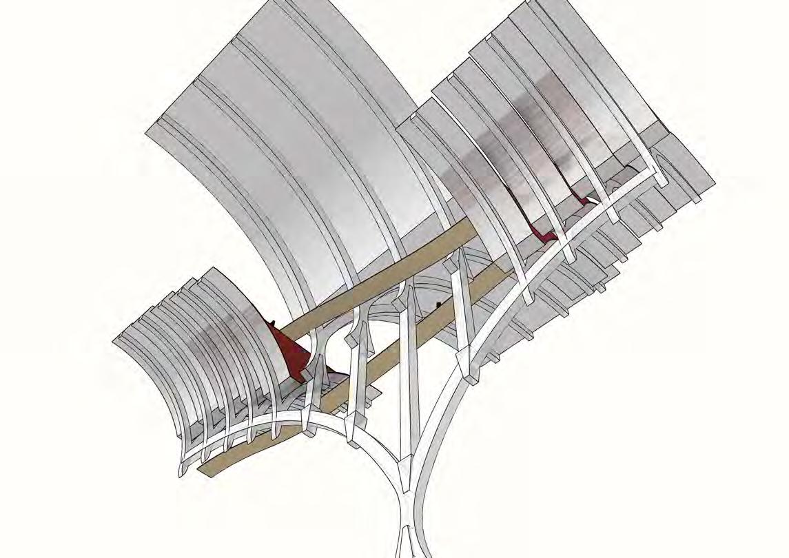
The truss acts as the spine of the system. Bending it at different horizontal and vertical angles allows more complex curvatures.
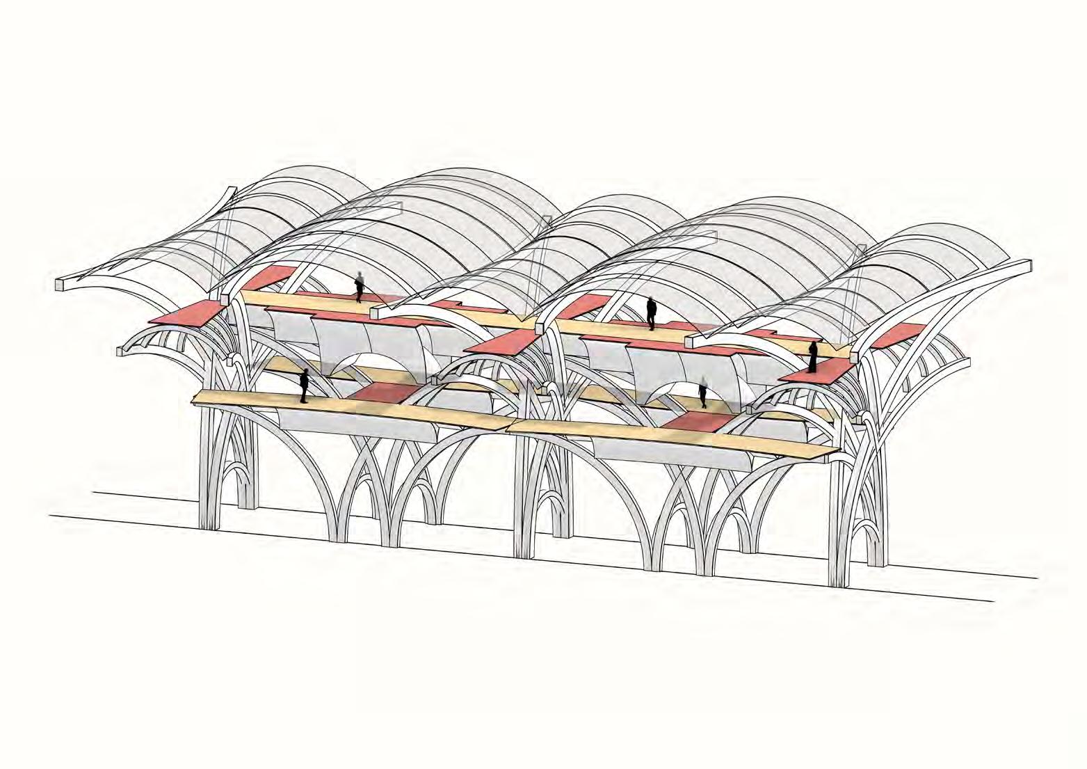
Recursion - Stepped Tectonics
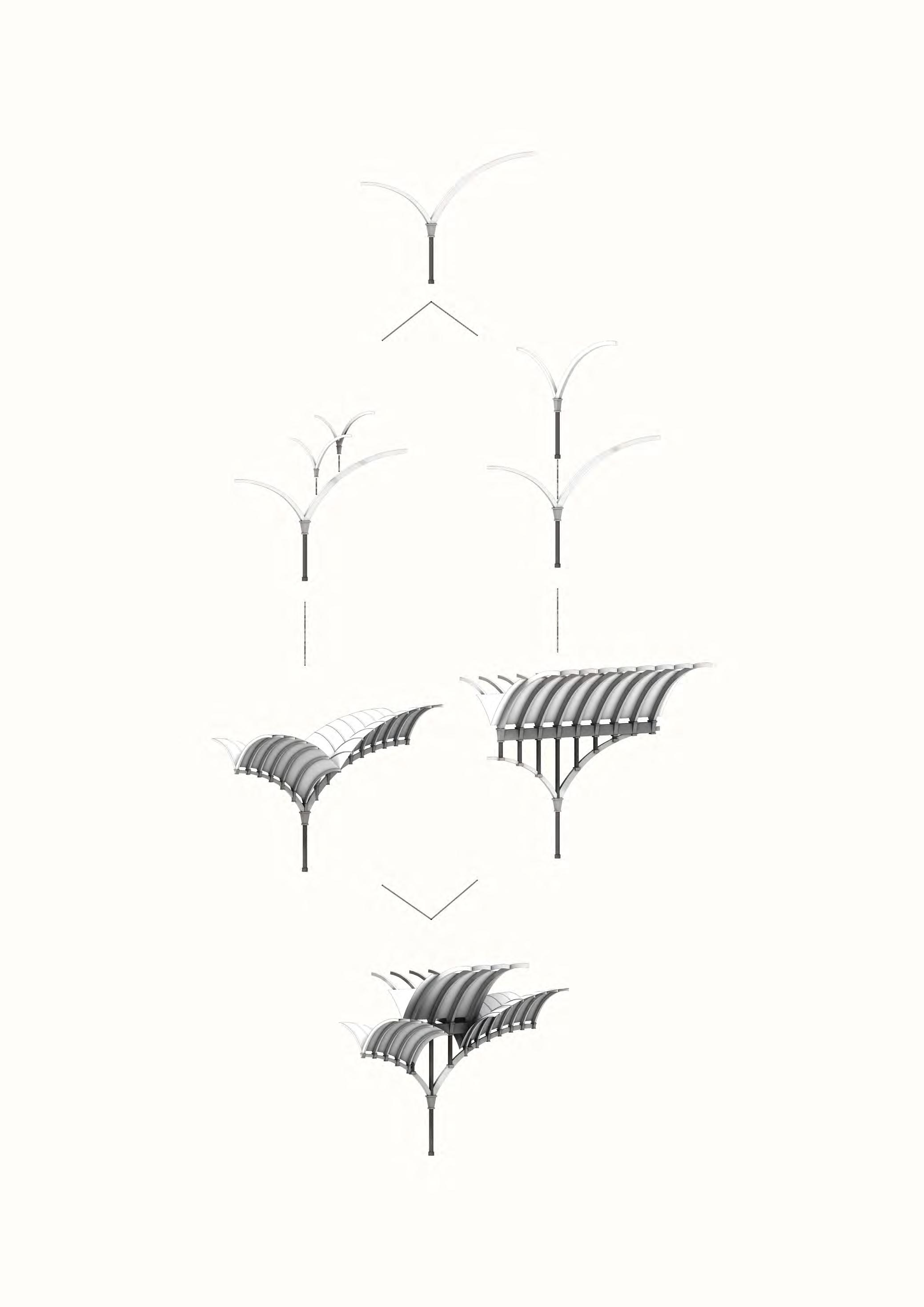
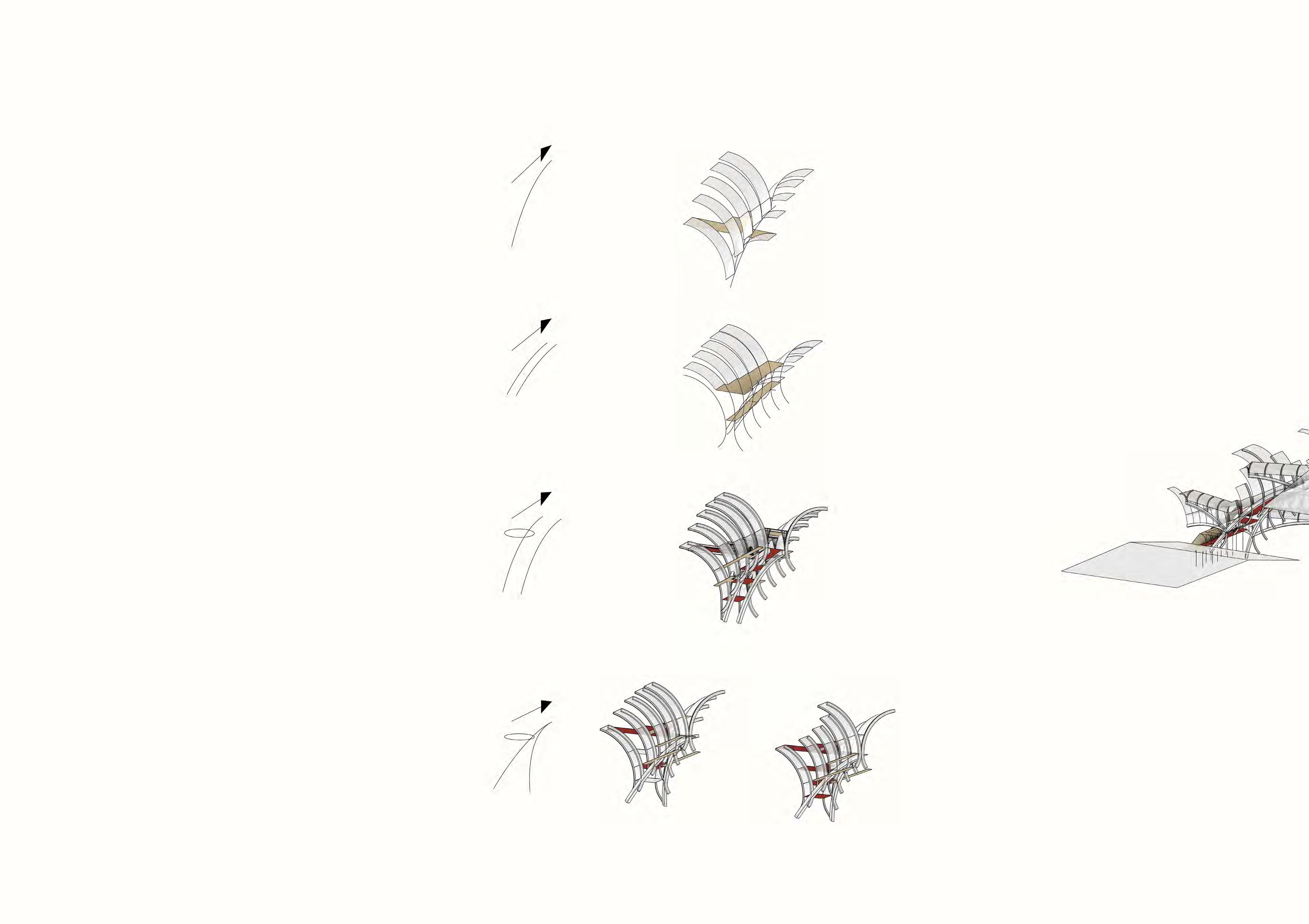
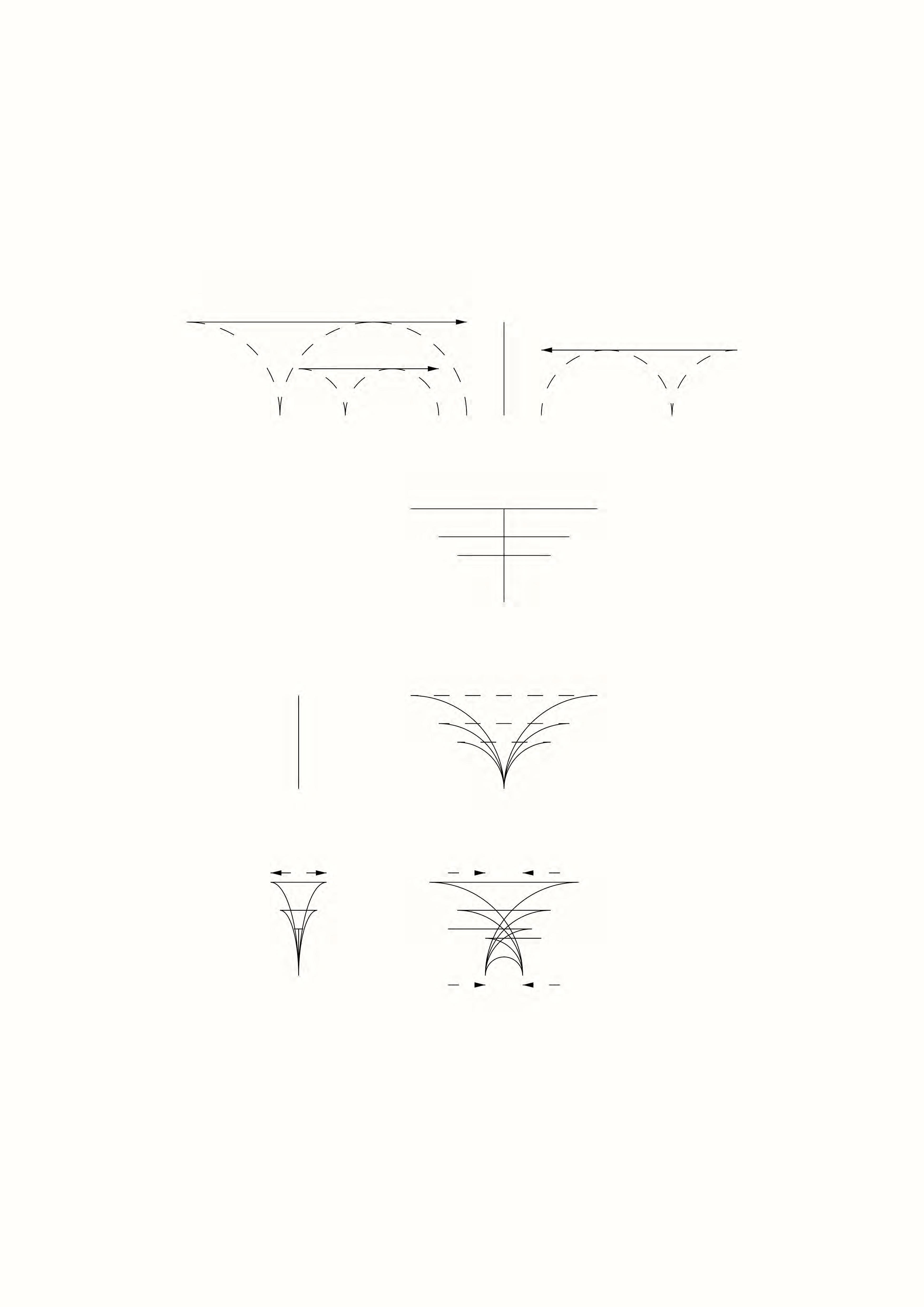
The module consisting in a column with two branching out arches can becombined through methods of stepping an recurrence to expand the system onto several levels, creating openings and flow between vault fragments.
Assembly Iterations
2.2. Recursion of scaled down arches placed perpendicularly on the
4. Combining both methods to create the design language.
1. Column and arches module.
2.1. Repetion of the module placed perpendicularly above.
module.
3.1. The system is extended linearly above the module.
3.2. The roof follows along the arches of the module.
Worm’s Eye View
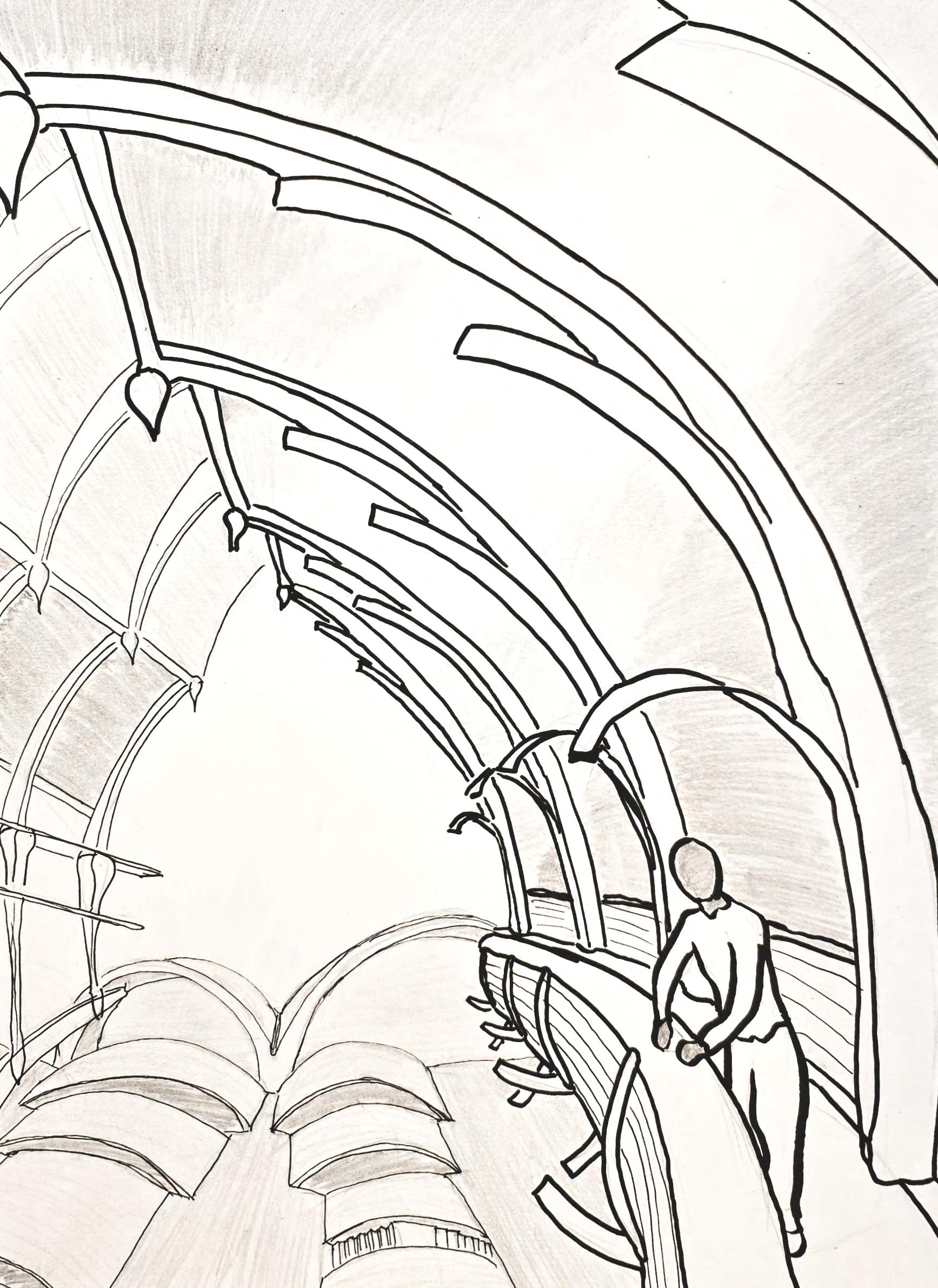
Looking up, the space created conveys the atmosphere of a cathedral, through layers of arches and openings.
The assembly offers multiple opportunities for spatial tectonics. Vaults can translate inot circulation platforms, widows and balconies.
Artefact
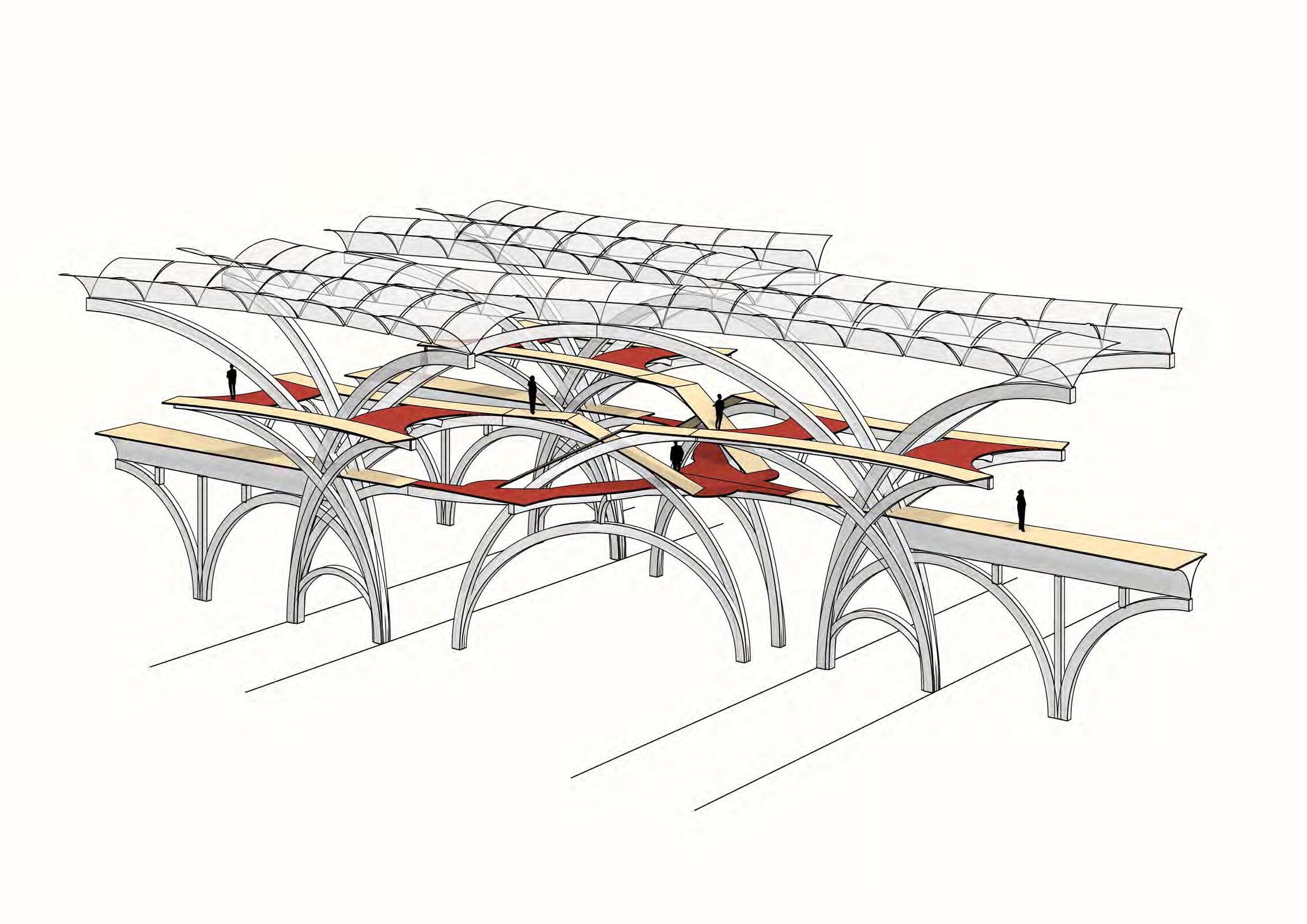
Massing - Circulation
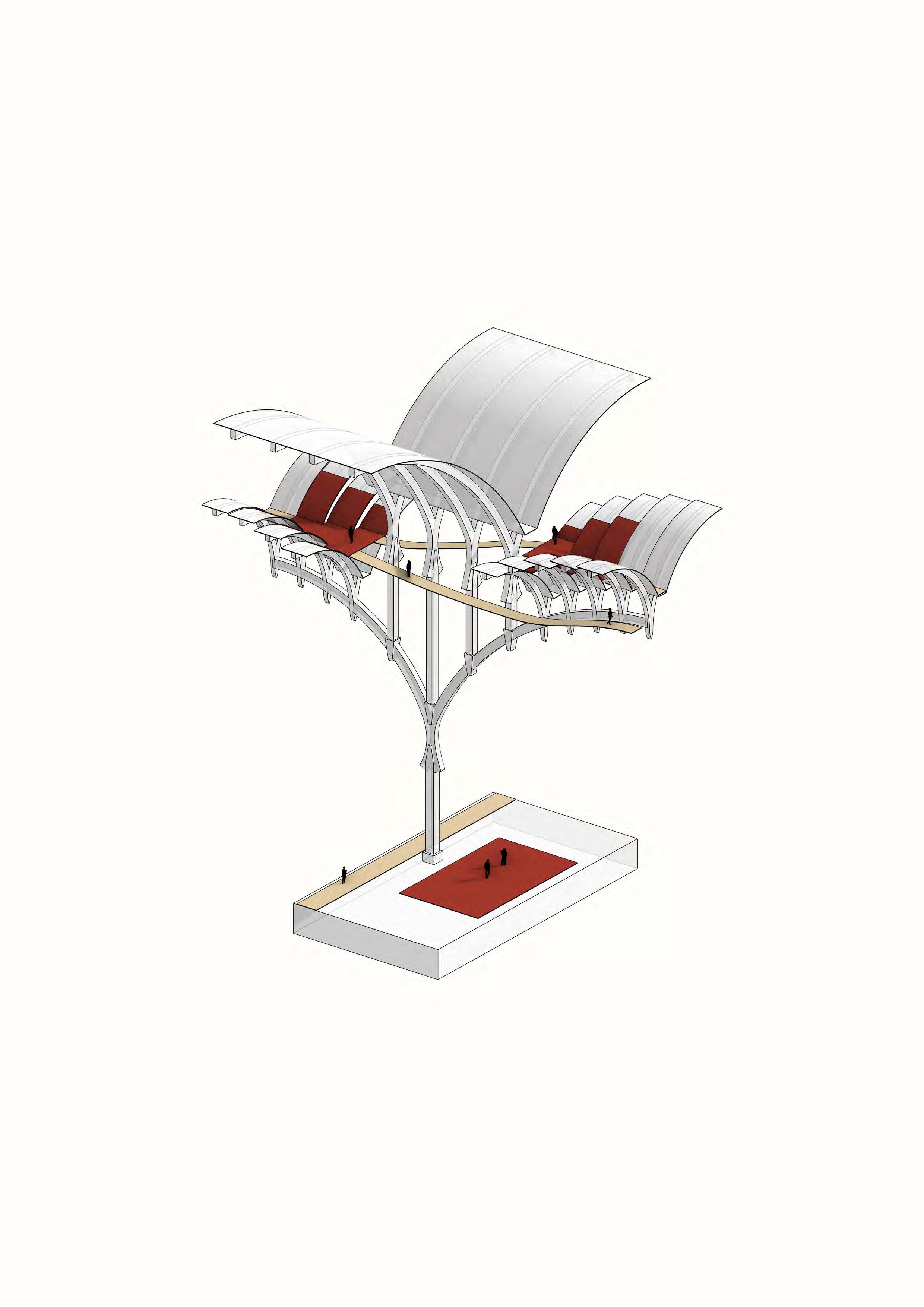
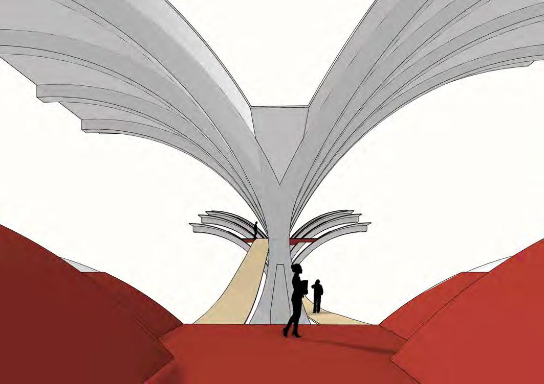
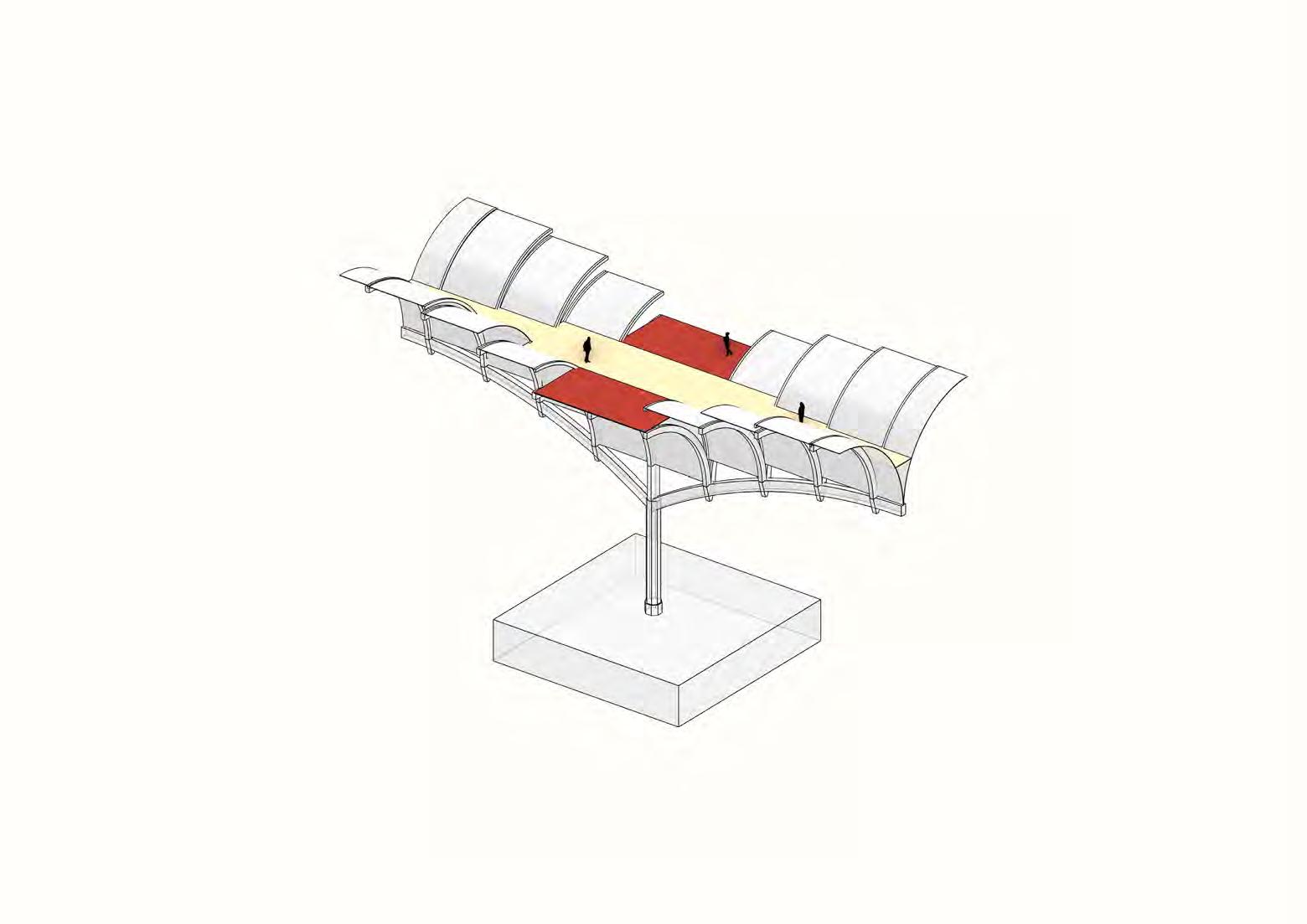
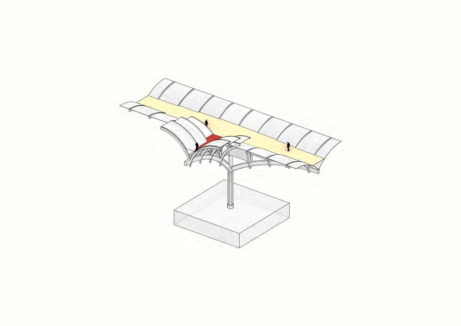
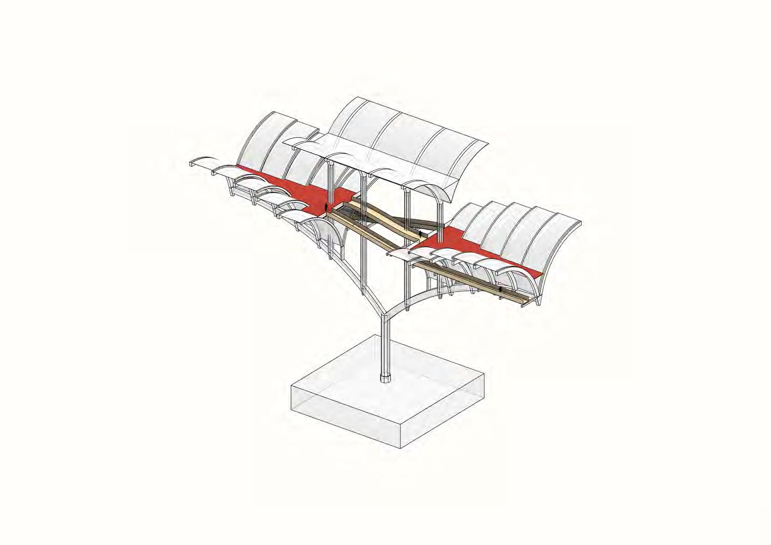
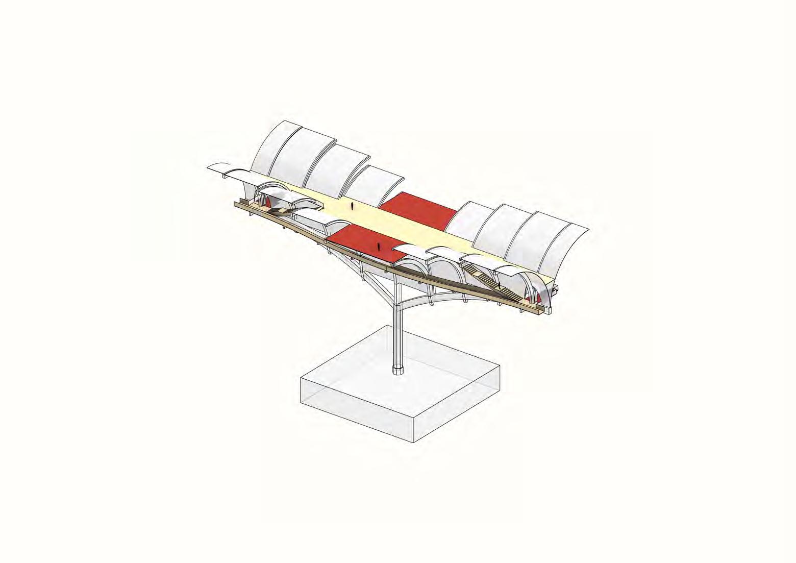
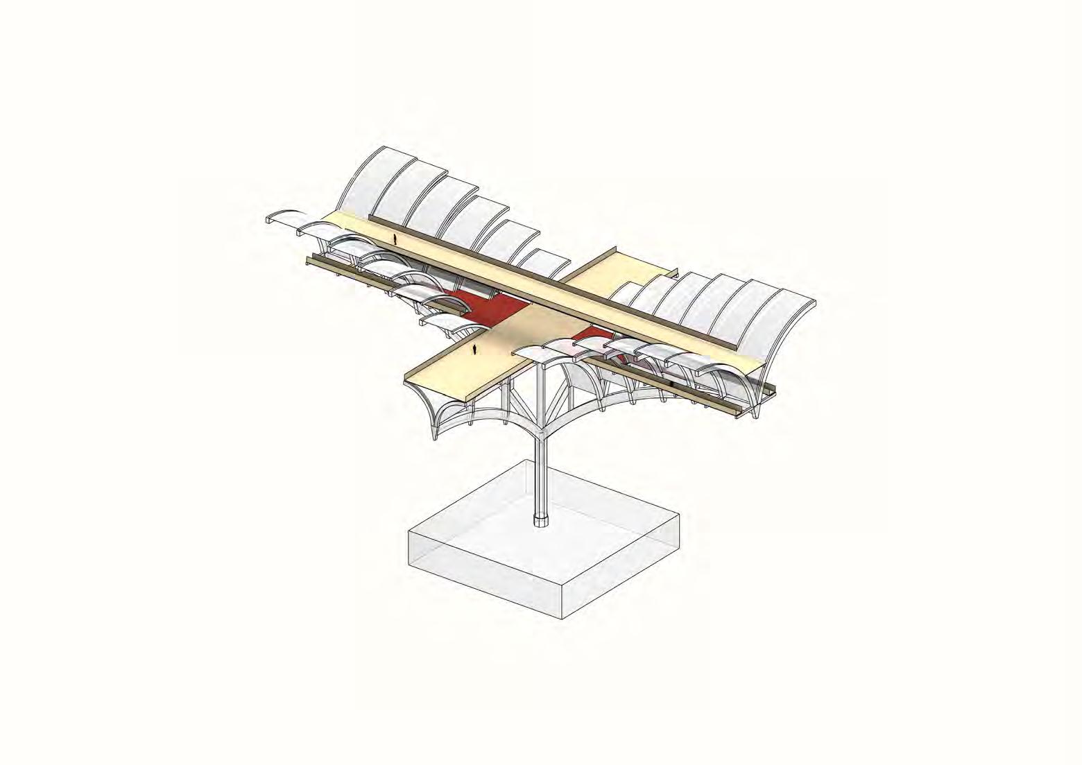
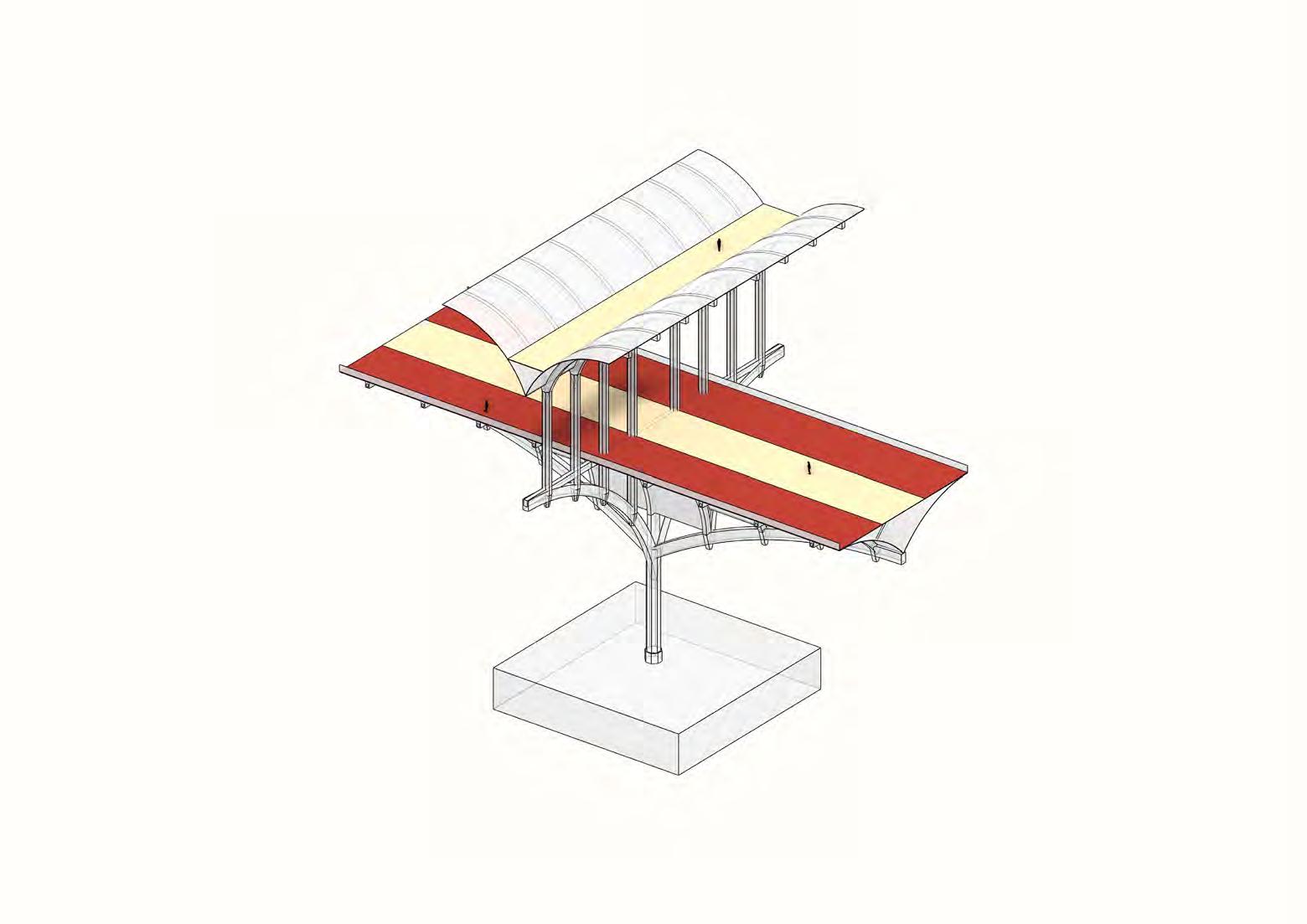
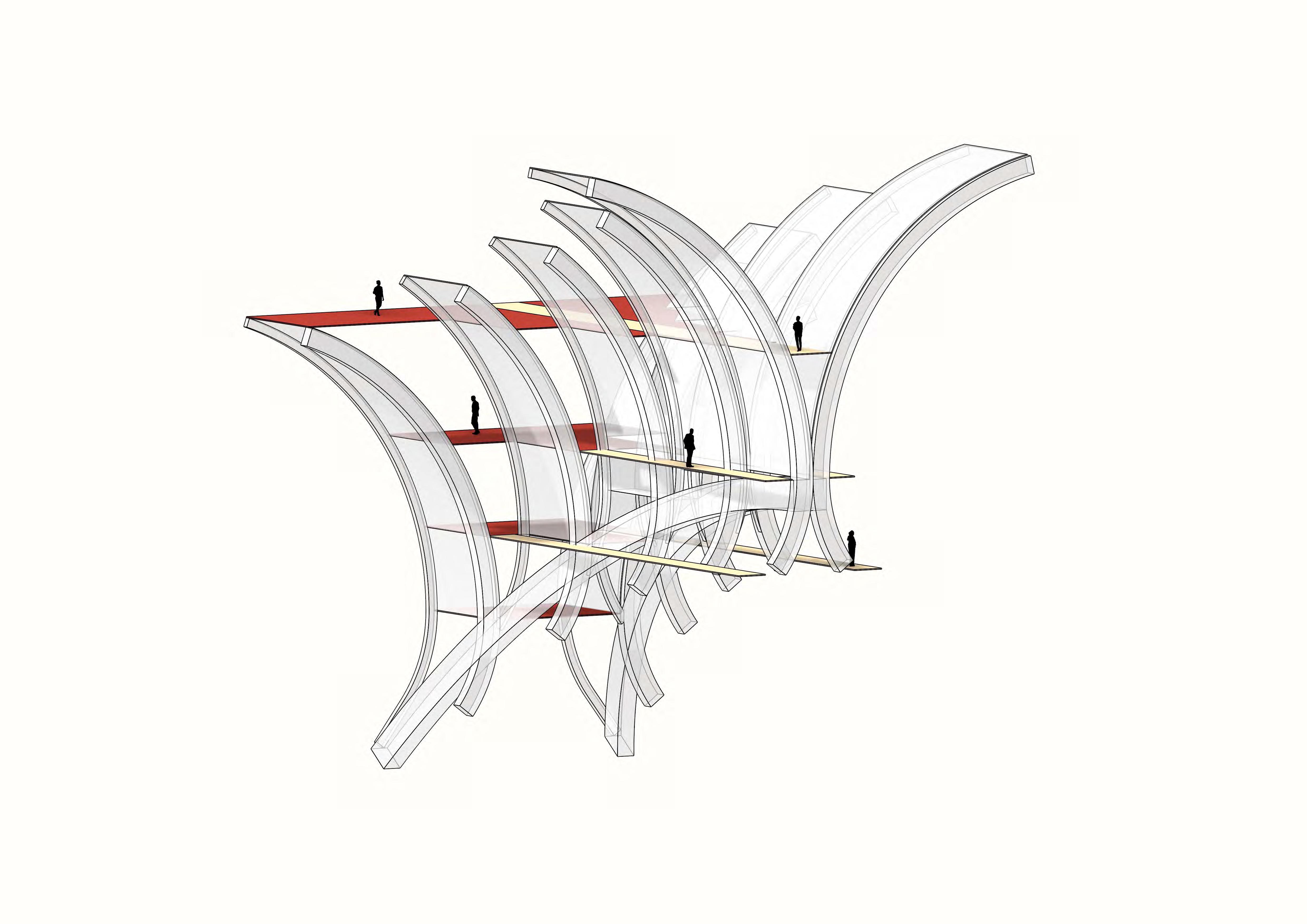
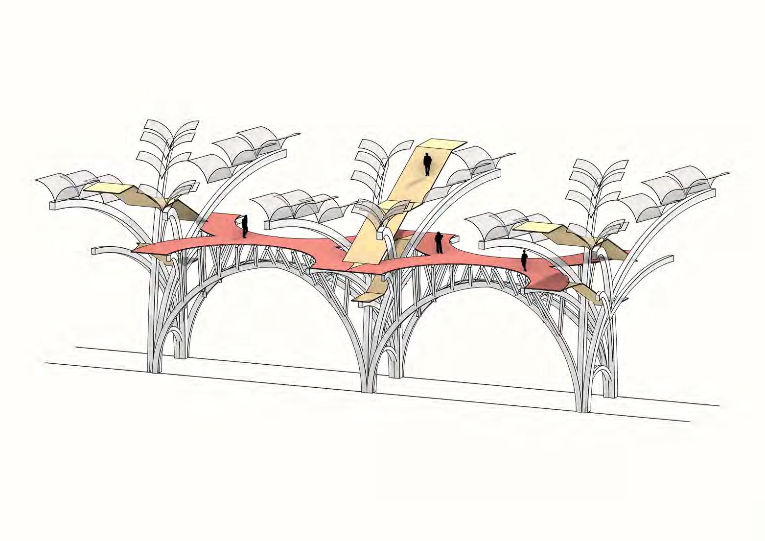
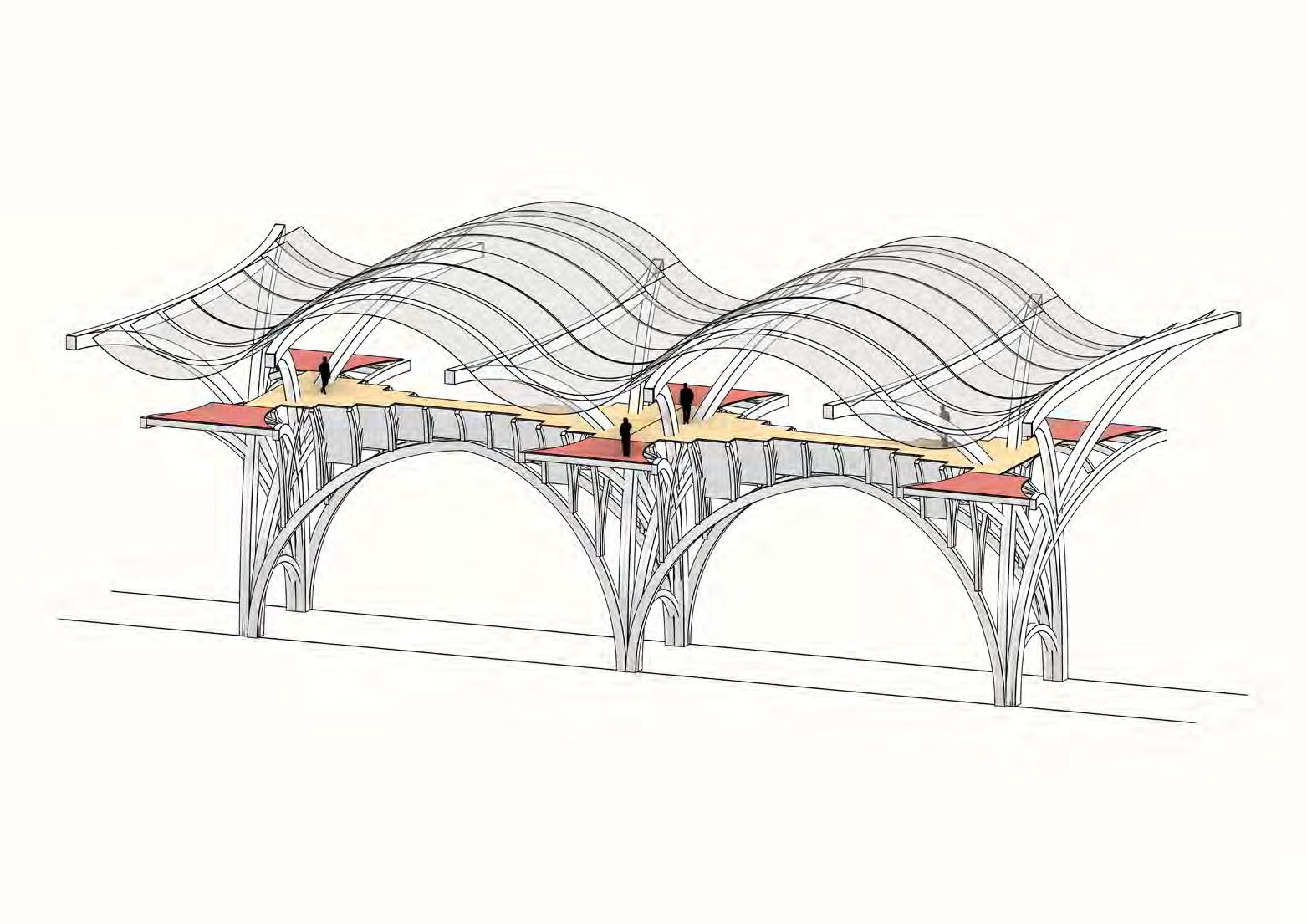
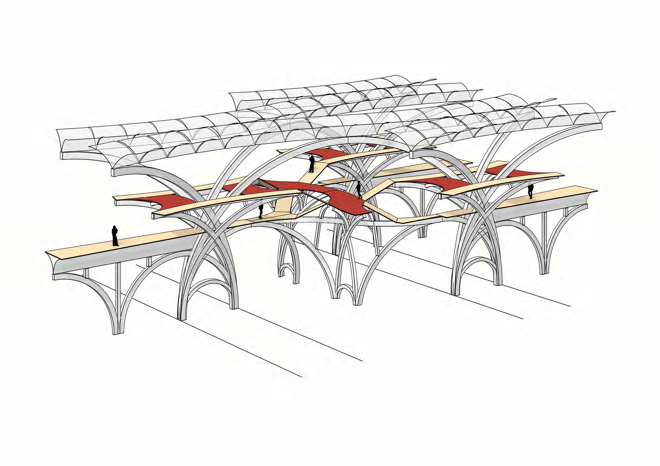
The circulation strategy treats the structure like a being in itself with which it dialogues. The pathways (human scale) and the structure (building scale) create an unavoidable contrast for the user experience.
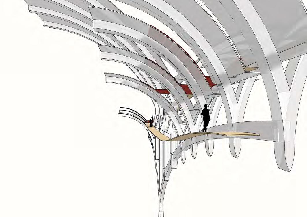
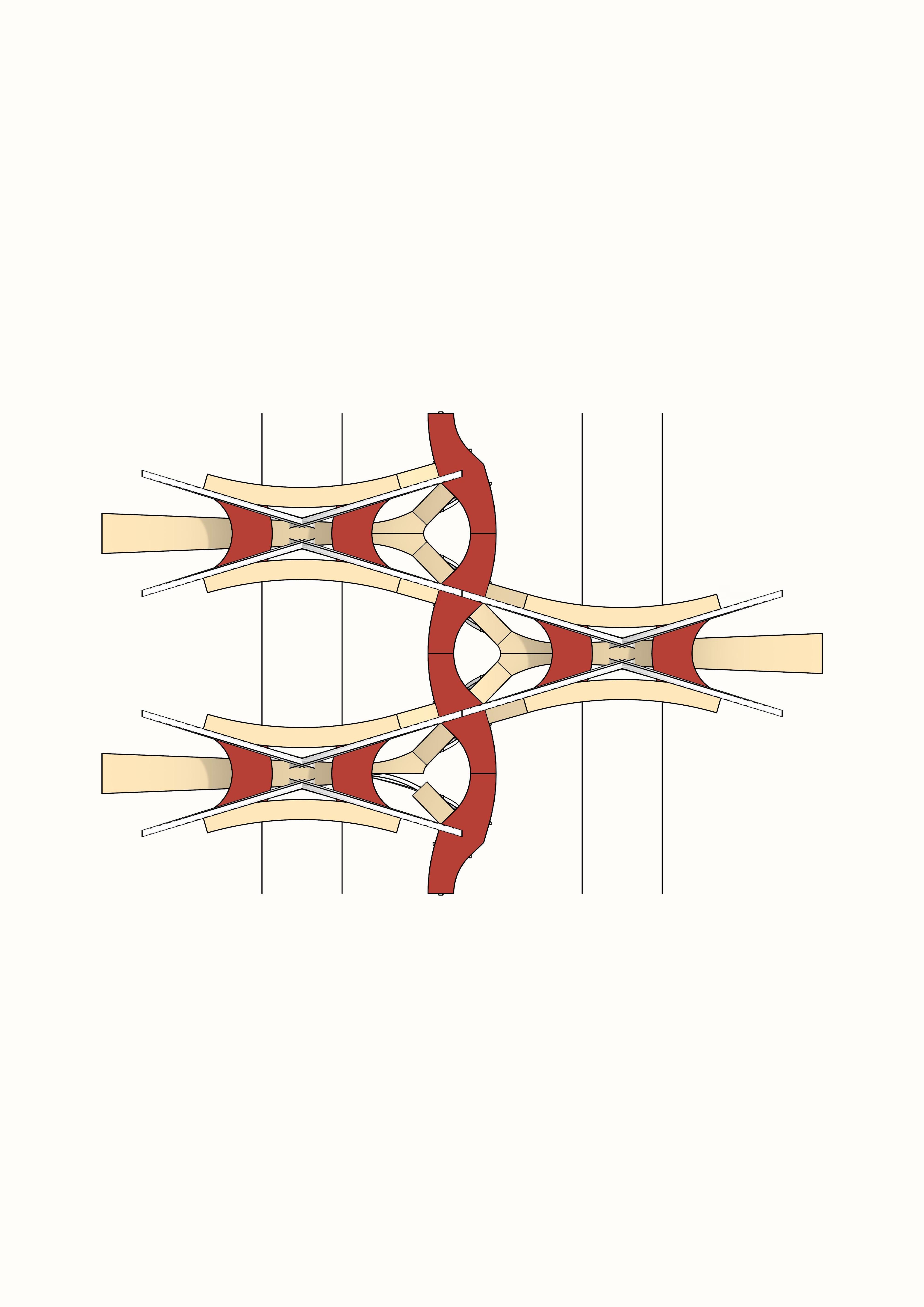
Multiple spaces for program (in red) can be placed at various levels across the structure. The circulation paths (in yellow) present themselves as suspended ramps winding around pillars and arches.
User Viewpoints
The narrow platforms stretching along the large ribs of the vault invite the users to apreciate the difference between the human scale and the building scale.
Isometric View
The circulation axes between ground and mezanine levels intersect at the pillar, becoming a focus point.
Concept Sketch
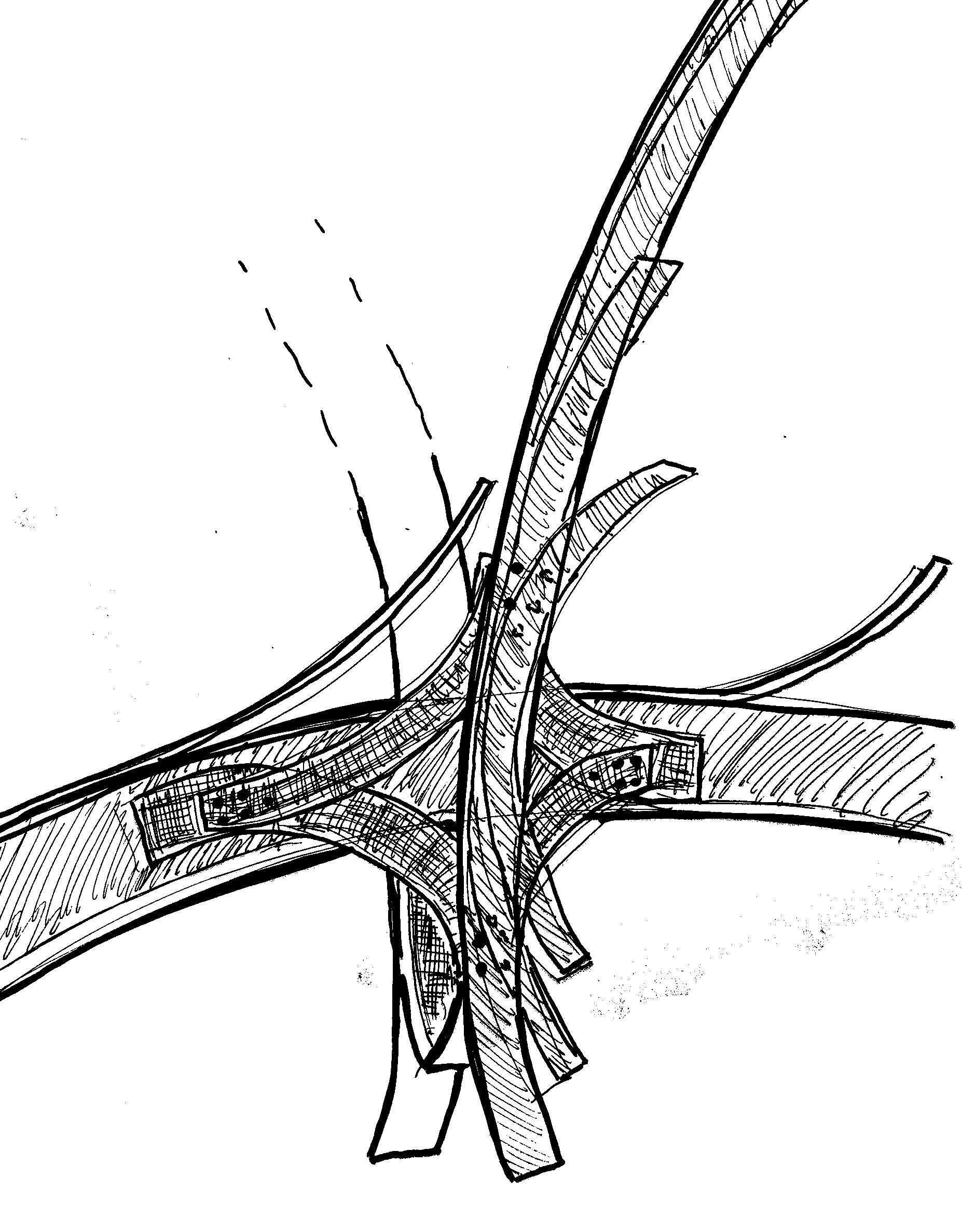
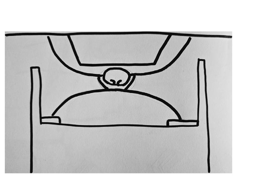
This abstract sketch expresses the relationship between the person and the void. The structure curls around the pathway to balance the experiences of thrill and safety.
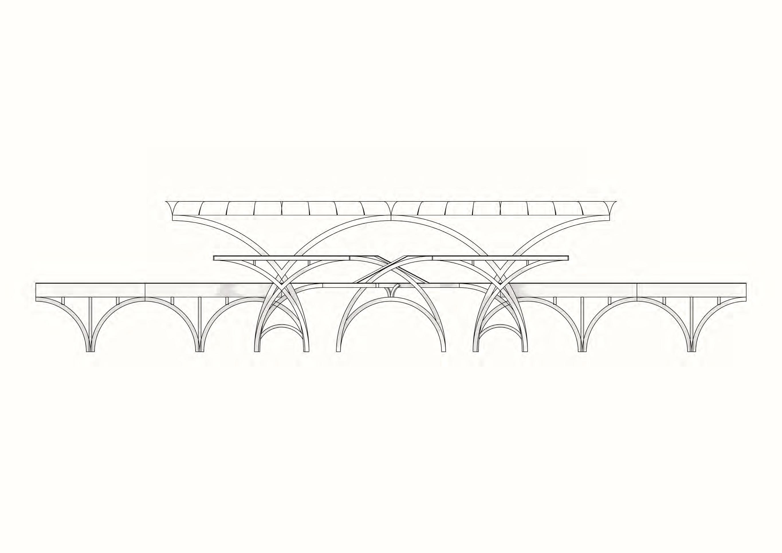
Design Language - Joinery
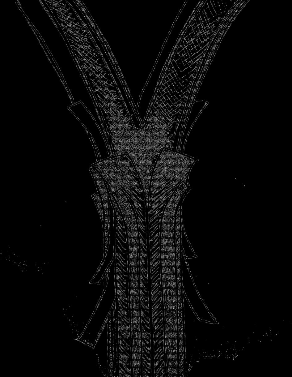
The structure is inspired the composition of a tree: roots, trunk branches, canopy. The different elements are formed by ribbons clamped together and branching out organically. The curvature of the ribbons allow fluid and continuous shapes for seamless joinery.
Platform-Secondary Arch Connection
Plates curl out of the secondary arch to enclose the pathway and hold the platform.
Secondary-Primary Arch Connection
Plates coming from the sides of the primary arch blend into the form of the secondary arch.
Primary Arch-Column Connection
The arches curl down in a slit formed between the main panels of the column. The column plates curl up to introduce the arch curvature.
Secondary Arch
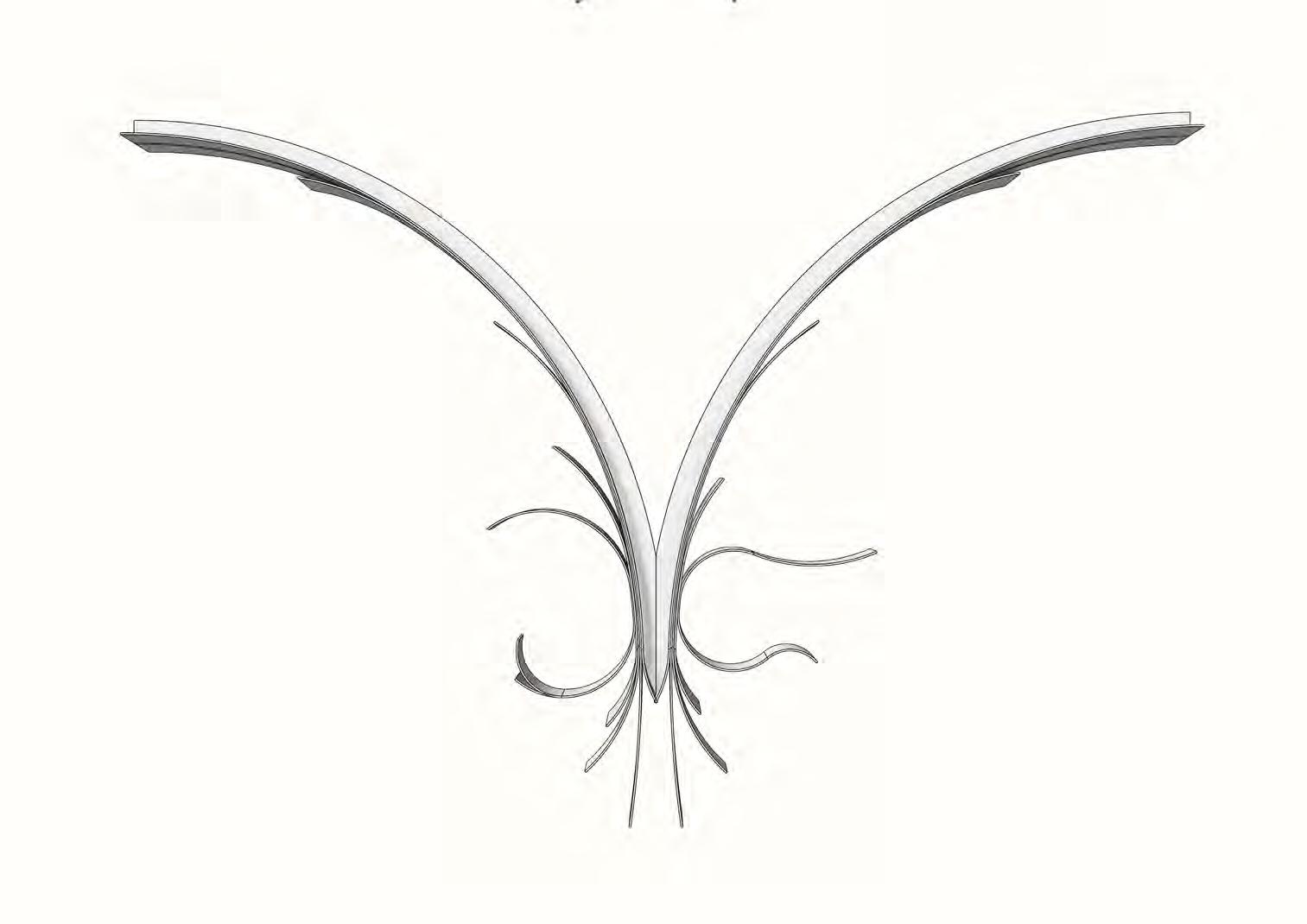
The secondary arch module is symetrical. It is balanced between the pathway enclosure on the left and the extending ribbons serving for wayfinding. The crease between the arches also offers space for program and circulation.
Primary Arch
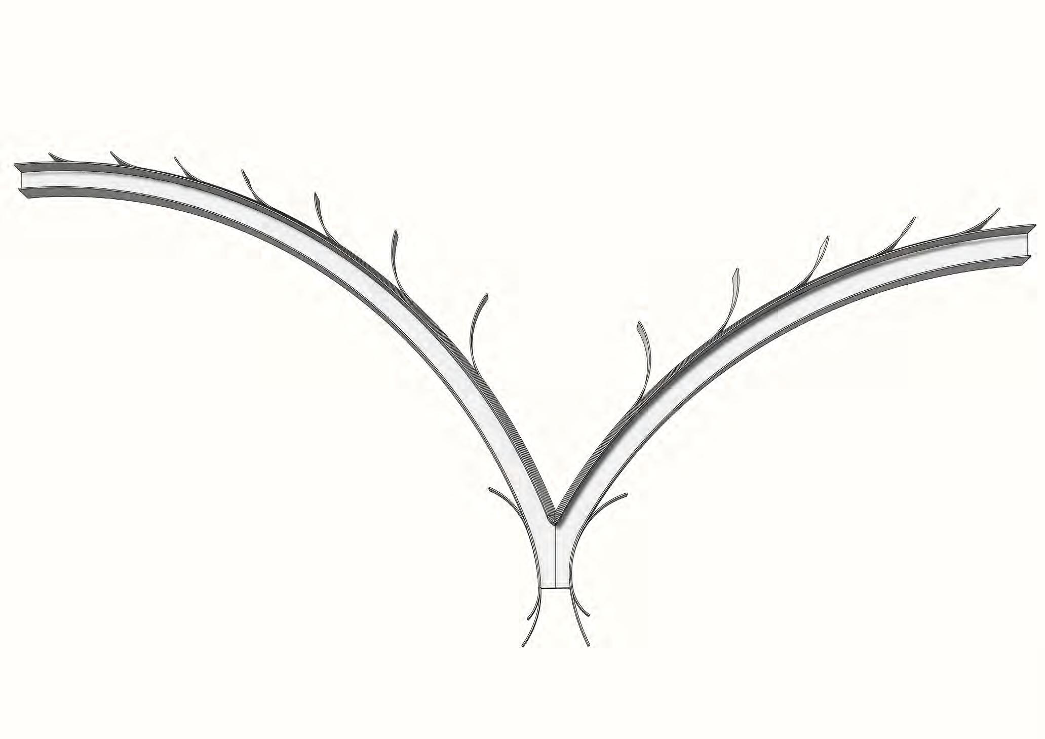
The primary arch module is asymeetrical. This creates two different levels to propose more intertwining. The top plates subdivide and curl up to accompany the secondary arches.
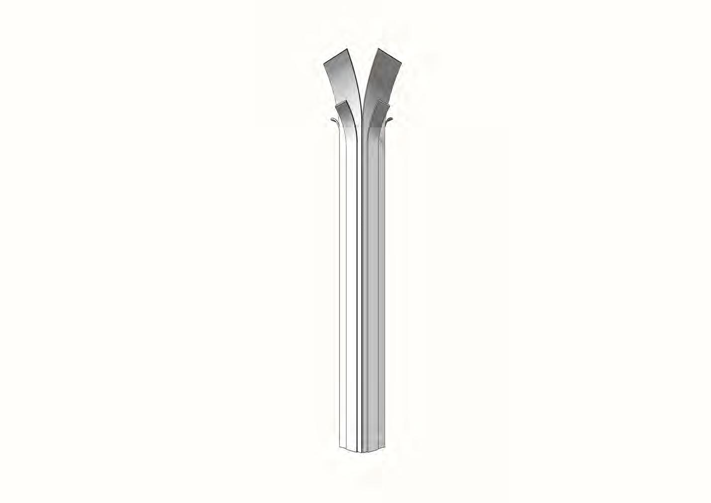
The column has a hexagonal base that expands into a capital following the form of the primary arch.
Column
Fragments - Circulation Typologies
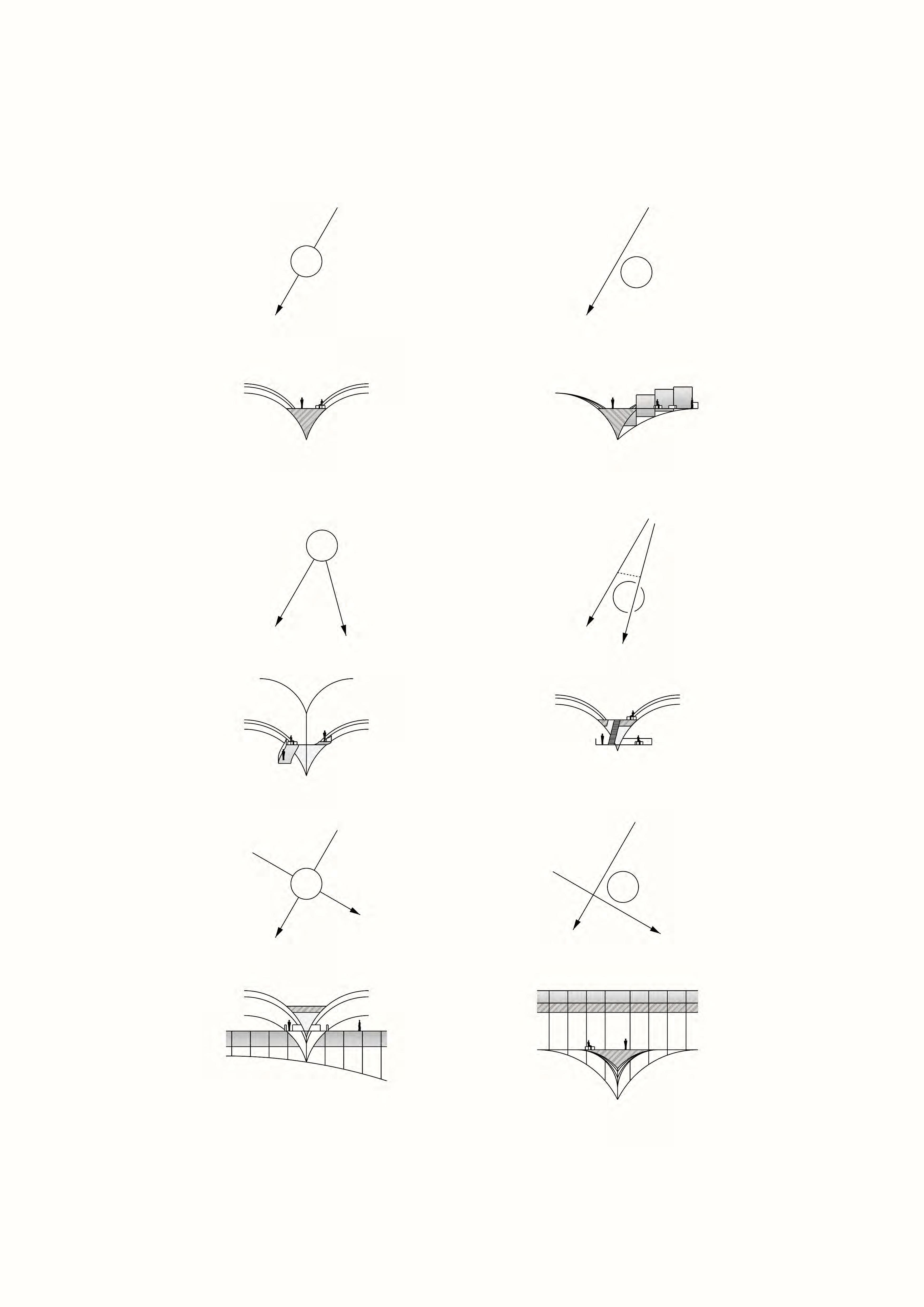
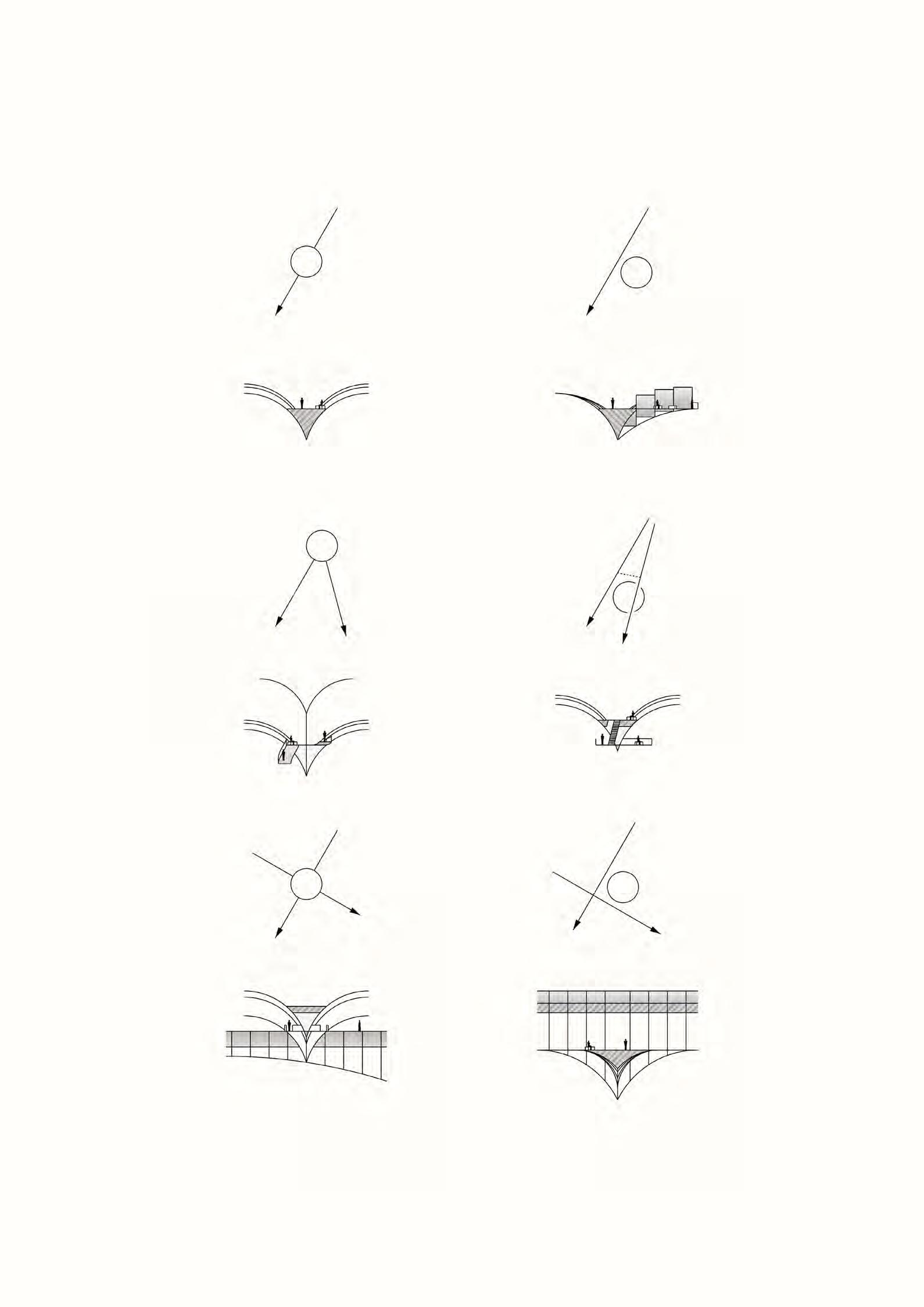
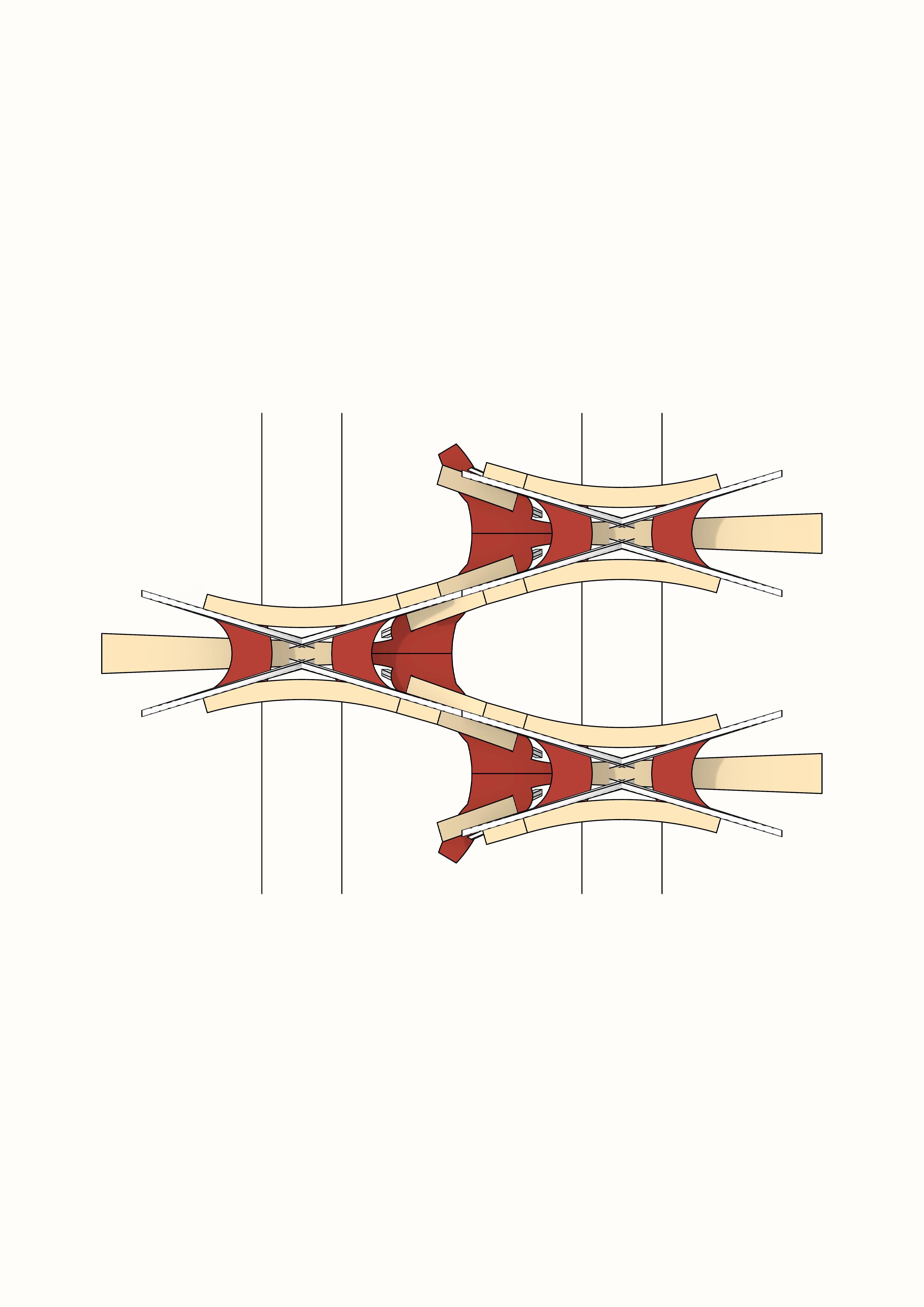
This exploration of organisations of circulation and interaction spaces aims to create new typologies which are then translated into building fragments. Playing with overlapping levels and intersecting paths yields abstract yet intricate assemblies.
Intersecting Paths
Single Path
Adjacent Paths
Diagrams - Inhabitation
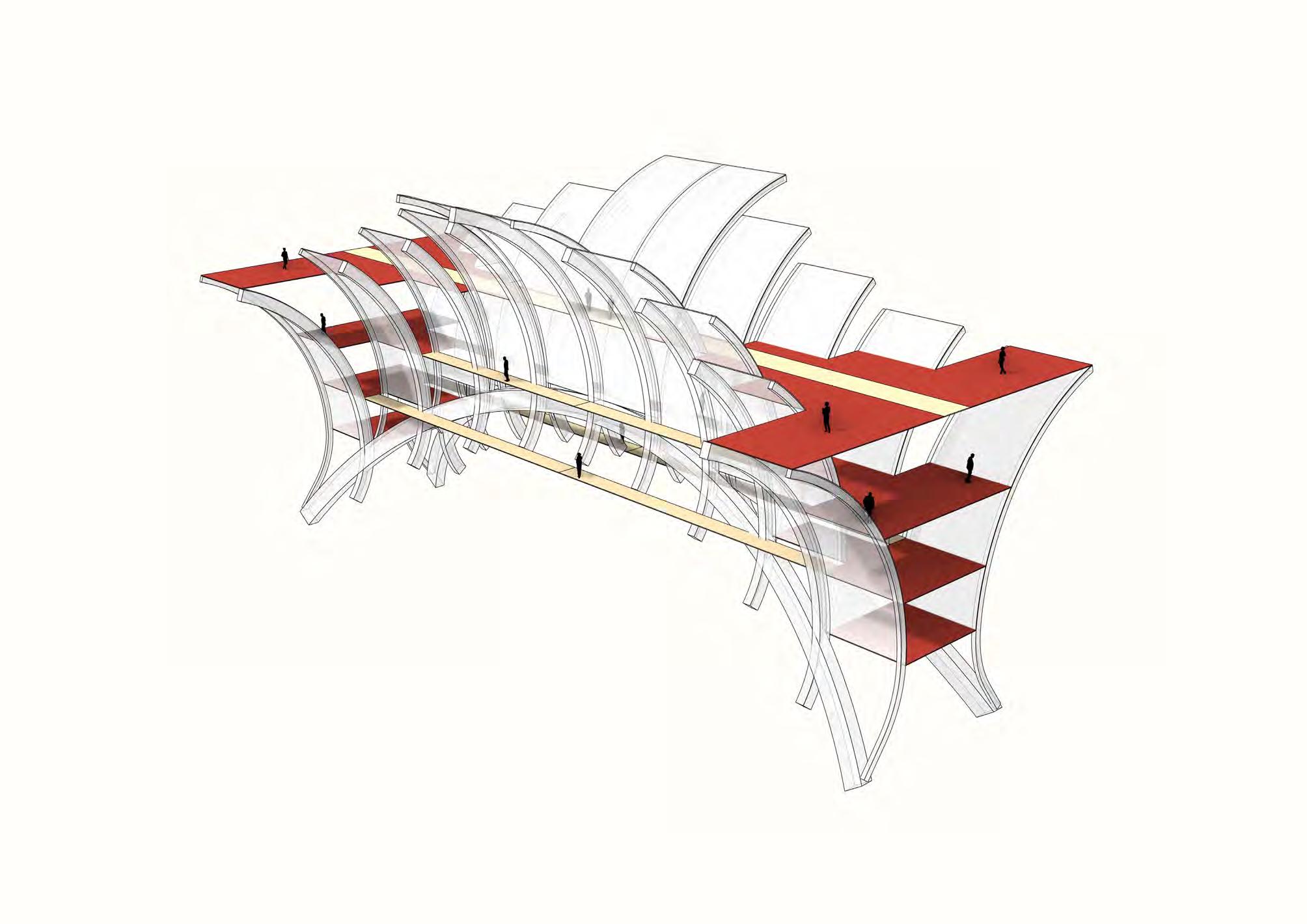
The “V” cross-section between two arches is expanded into internal terraces and external circulation platforms. The assembly is developed so that the circulation and the structural elements coincide.
Single Arch
The jaggered shells create a tapering pathway.
Double Arches
Two parallel arches leave an internal space in between.
Wide Double Arches
The internal space consists into stepped platforms.
Joining Arches
The gaps between the shells are increased to open to external pathways.
Isometric View
The complex comprises four internal levels of activity. The platfroms peak out of the building envelope, supported by the sympathetic structural forms.
Full Arch
The silhouette follows and hourglass shape with the external platforms linking together.
Expansion - Combining Tectonics
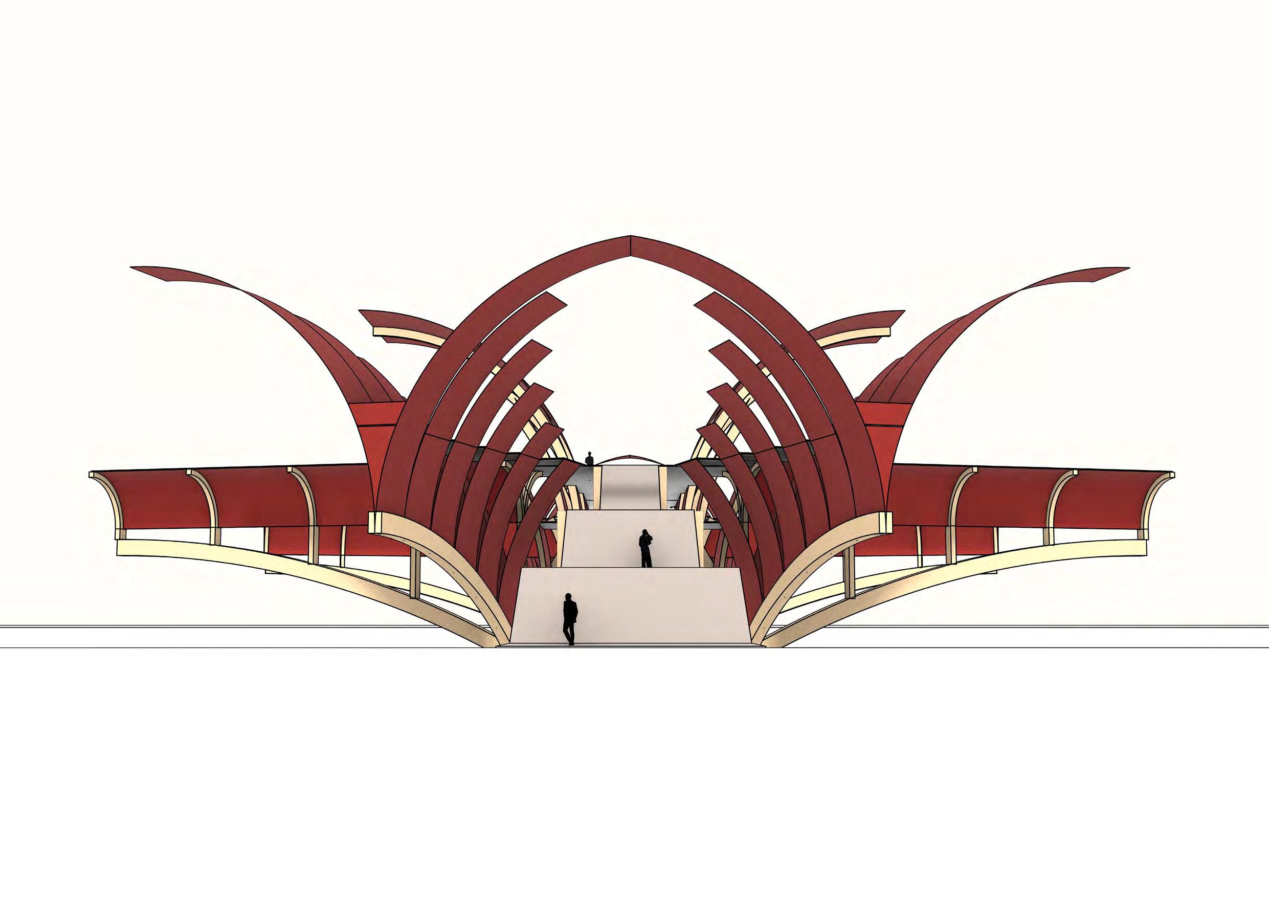
The inhabited bridge structure is expanded into a set of intersecting circulation axes. The arch is both used as a space boundary and an extending structural element.
Entrance View
Combining the stairs as ascending elelements with the arches as portal elements results into a monumental composition.
Elevation
Arches overlap according to the structural hierarchy.
The bridge is adapted to a river crossing adapting to sloped terrain on each side. The shells are amplified as they are further from the nodes, creating enclosures.
Fragments - Intersecting Tectonics
This study investigates ways of merging multiple levels of circulation into one module, using arches of various radii as expressions of the levels. Bridge typologies merge repettetive structures with winding circulation and program.
3 Levels of Circulation
Intersecion with Vertical Axis
Arches Meeting at the Bottom
Shifting the Arches Apart
The resulting interseting arches provide opportunites for structural reinforcement and weave the tectonics with the space.
Grid Pattern
The modules can assemble in a side-by-side configuration, where the top arches meet. The spaces are focused in the gap between each module.
Staggered Pattern
The modules are placed such that the top arches meet continuously, inducing a half-drop match, This creates more spaces to focus around the modules. The circulation winds around the modules
Variations - Linear Rows
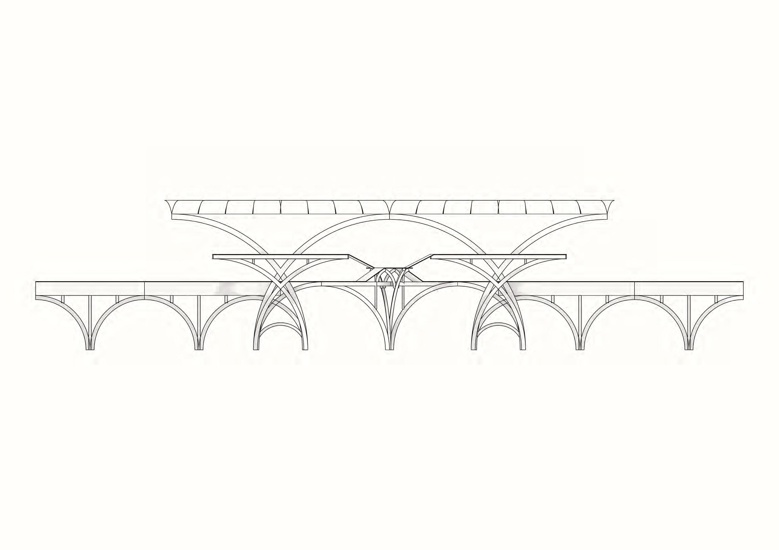
The four iterations propose space and circulation organisations that follow the tectonic language of the modules. The issues of density and clarity are balanced with the intuitive utilisation of the structure. Single Level
The pillars are linked with arches creating a platform tapering in the middle and expanding around the pillars.
Double Level
A secondary element is introduced, conssiting in double arches which meet across the pillars. The centre element can expand to create wider terraces.
Variations - Staggered Rows
The two iterations study how levels can intertwine and create spaces at their intersections. This requires a new structure between the rows, which can conflict with the modules. On the other hand, the more irregular configuration suggests a main axis that crosses through it.
Main Circulation Below
The middle structure leaps above the main circulation, following the staircase paths. Although, it does not follow the structural language of the modules.
The middle structure now follows the modules’ structural language. It forms a distinct footbridge in the middle.
Site & Context
An analysis of the site and its role in the context.
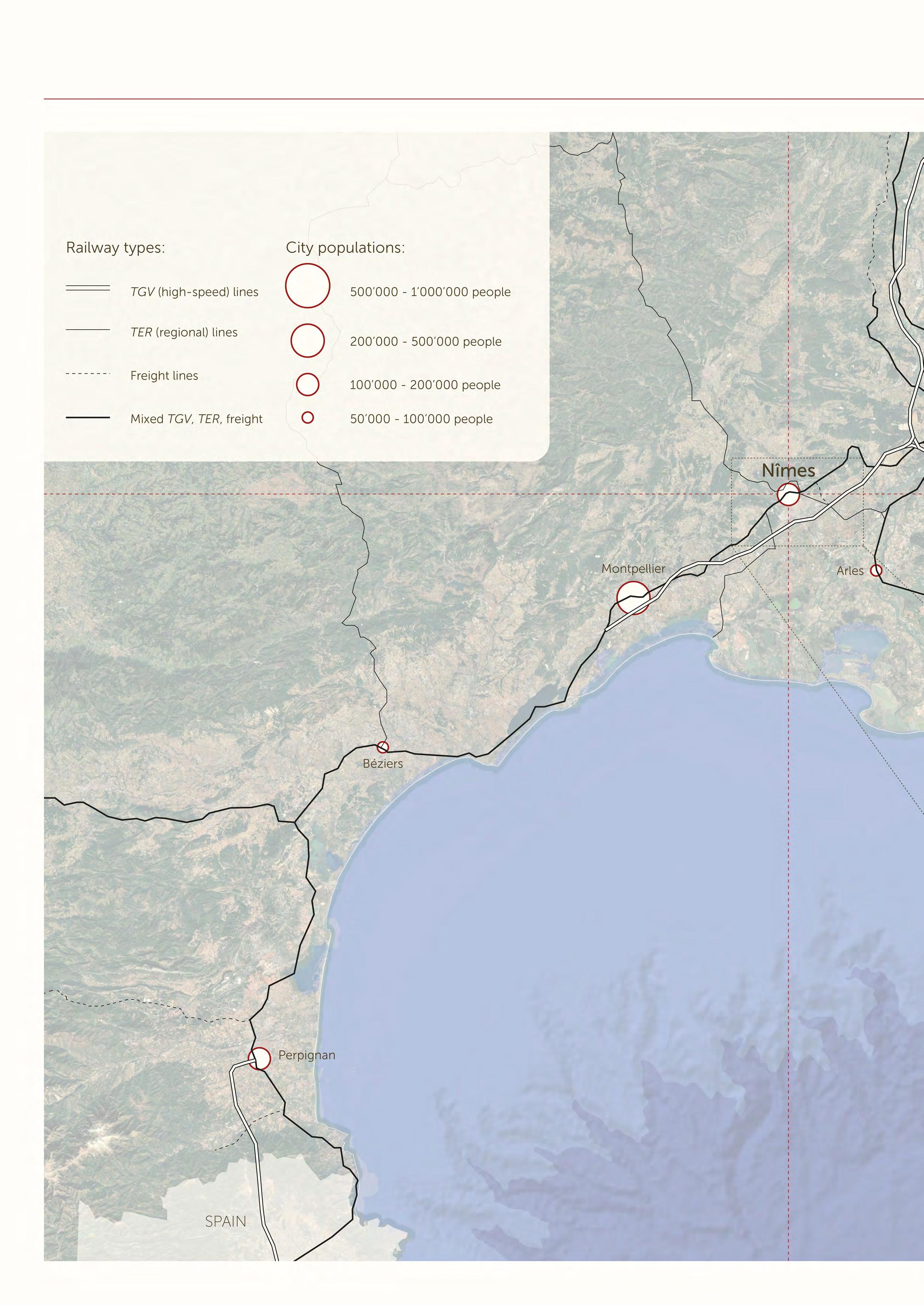
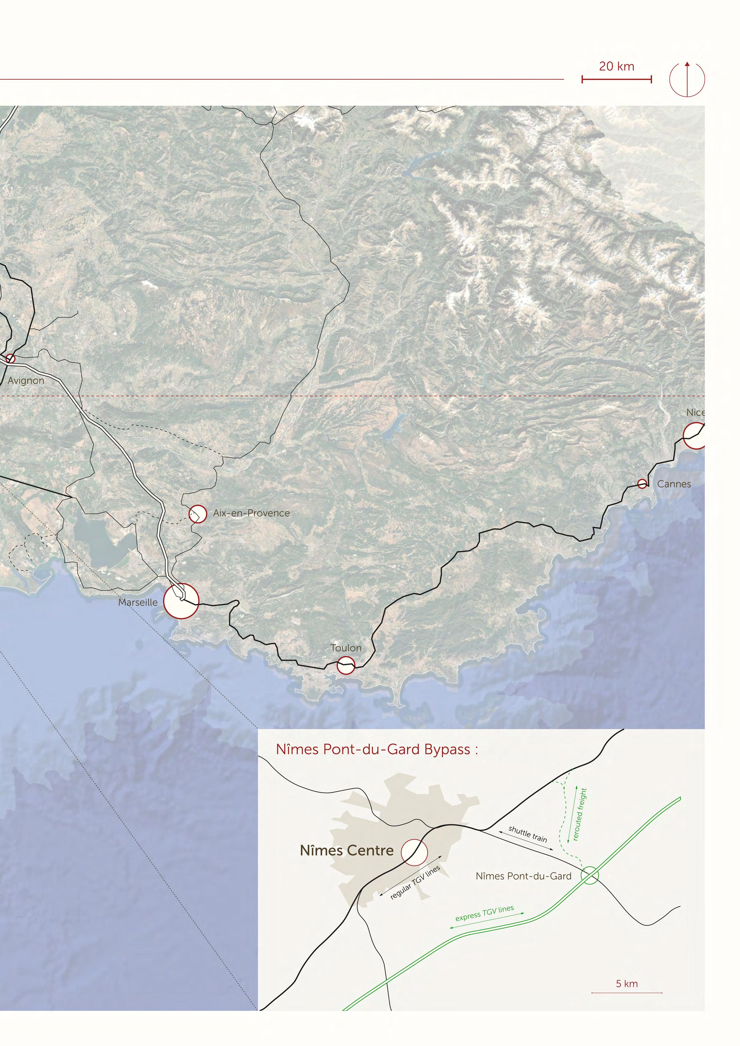
Nîmes on a Growing High-Speed Route - 1 : 1’000’000
Nîmes is on a major high-speed railway line between Marseille and Barcelona. However, the newly-built Nîmes Pont-du-Gard enables a bypass outside of the city for quicker journeys through the region. On the other hand, the Nîmes Centre station brings connectivity and tourism to the city itself and requires further expansion, with a 25% train traffic increase 2025-2030.
Nîmes - The French Rome
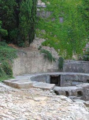
Former Roman colony during the first century B.C. and developed under Emporor August, Nîmes has grown to become a 150’000 people city and the capital of the Gard Department in france.
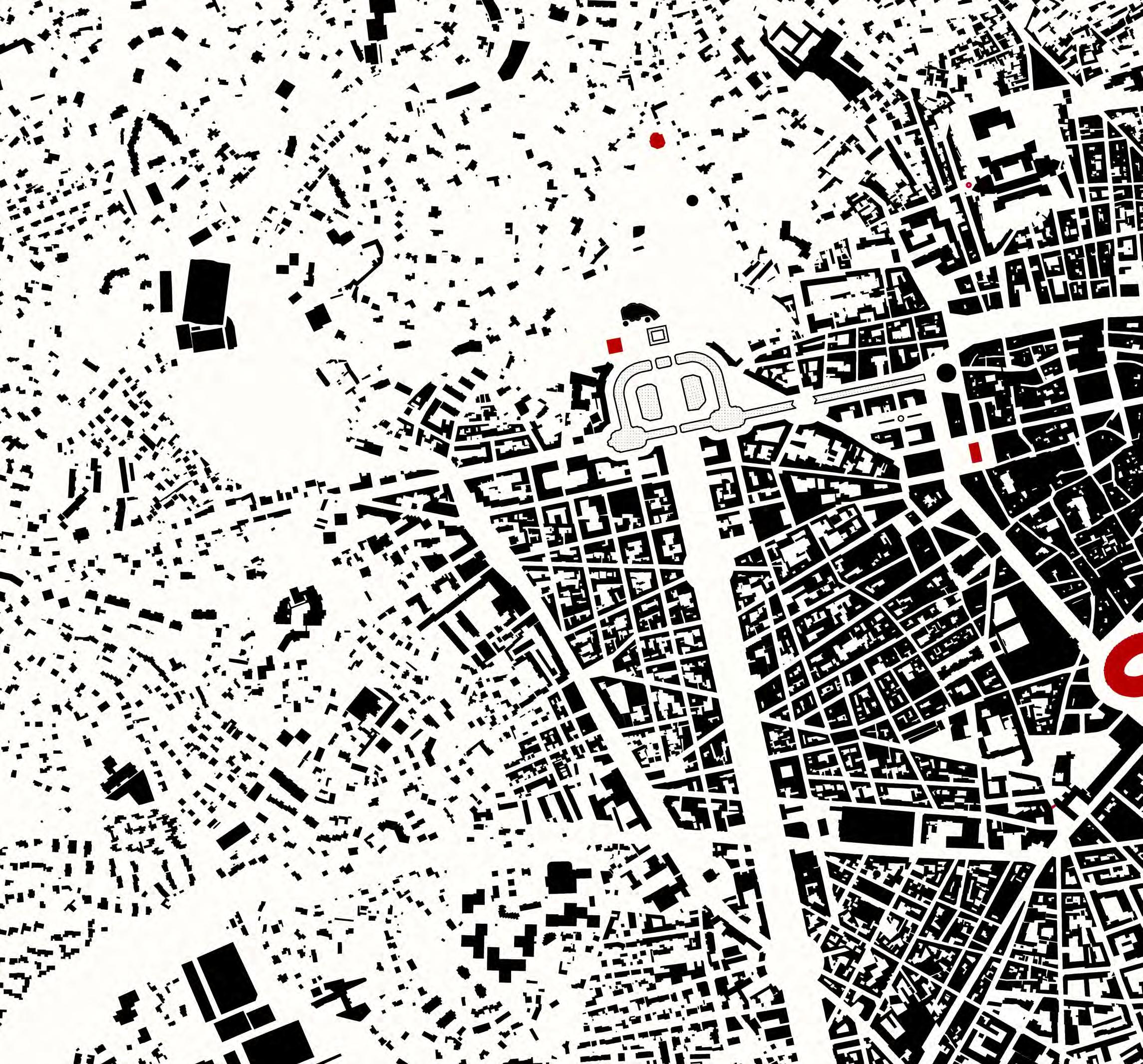
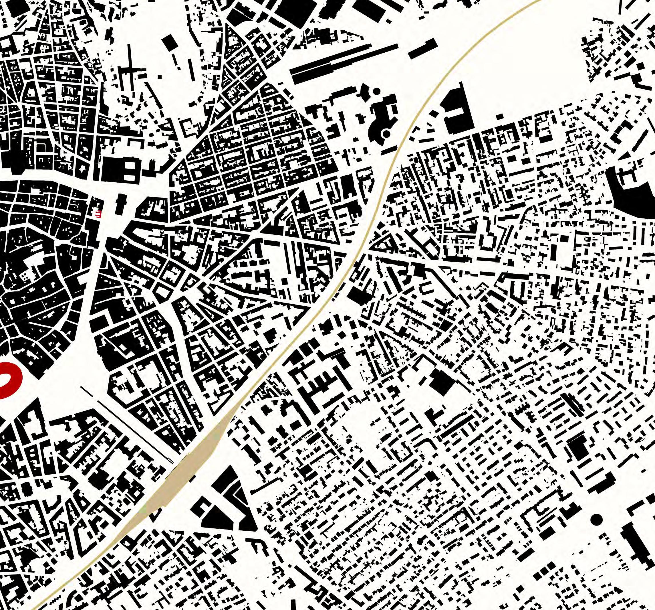
City Map - 1 : 5’000
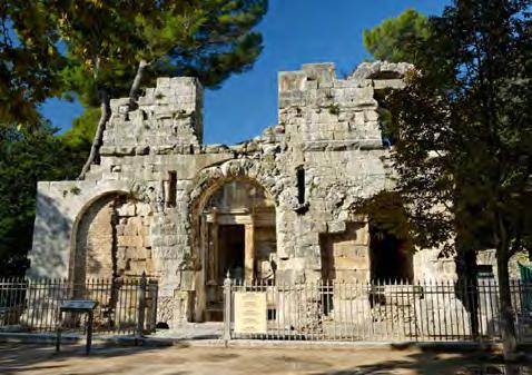
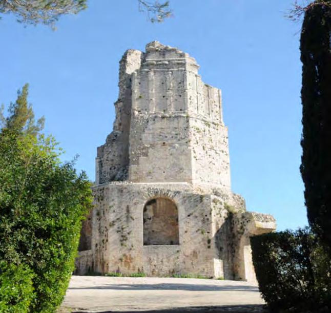
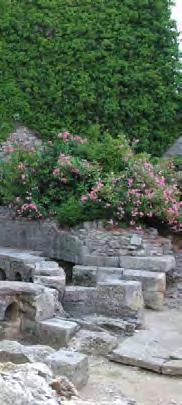
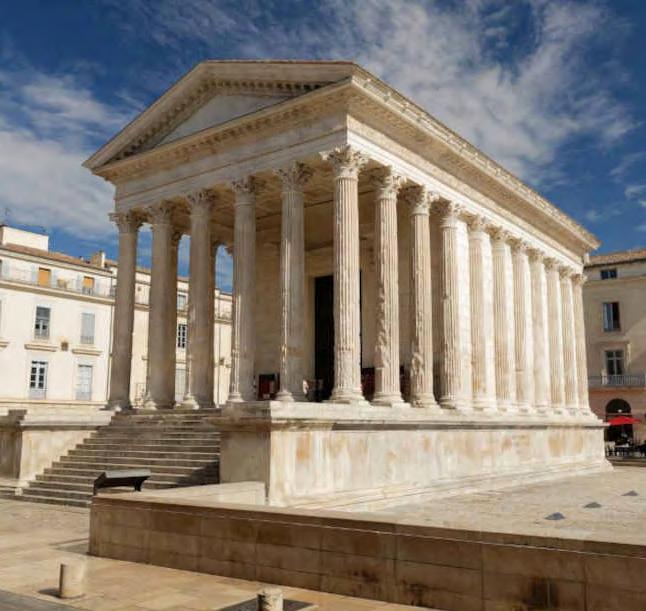
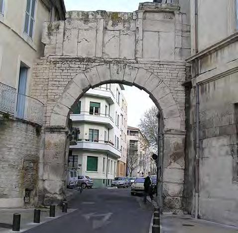
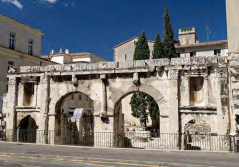
The city is surrounded by exceptionally well preserved roman ruins.
Diana Temple
Magna Tower Castellum
Square House
France Gate
Arenas
August Gate
Site
Pedestrians
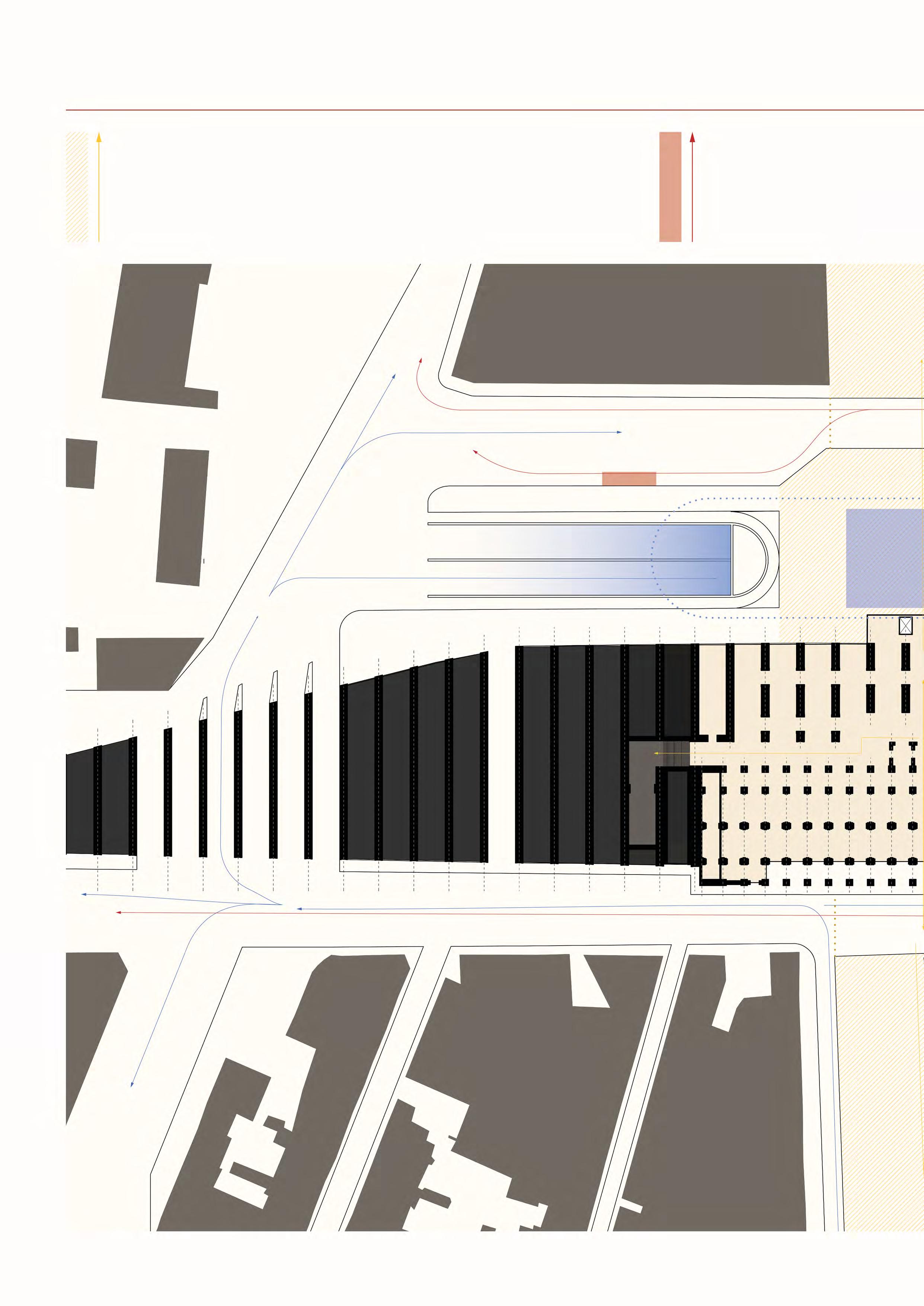
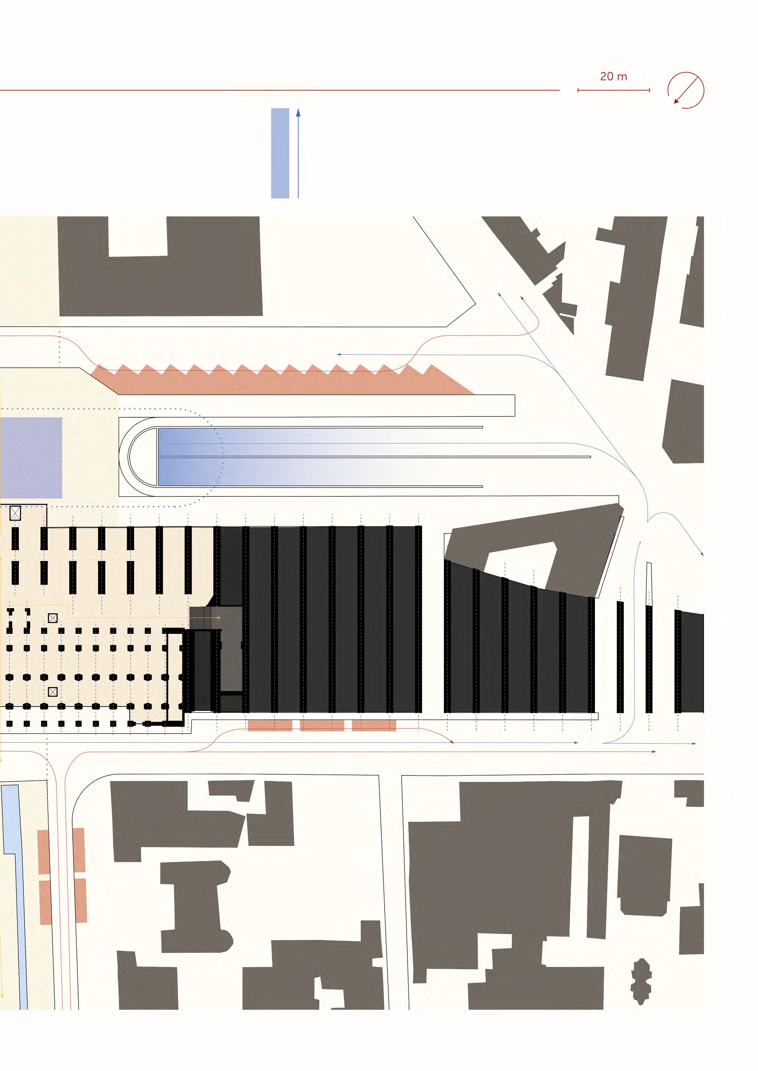
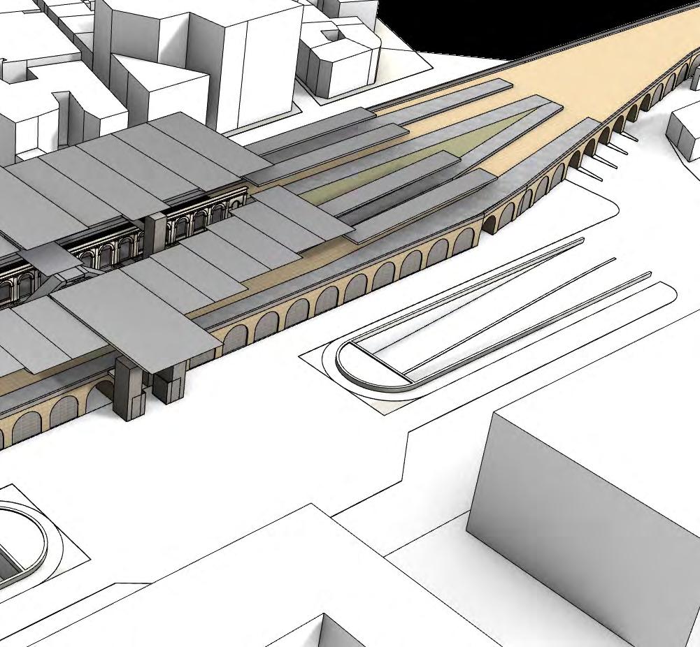
The station lies on the axis of the Avenue Feuchères and the Avenue de la Méditerranée, connecting it to the city centre and new developments on the South side. Pedestrians both use this axis to reach the station but also as a main circulation route in the city
Cars
The station also has an underground car park, with 320 parking spaces, serving 3’600 daily car users for the station.
Train Station - Existing
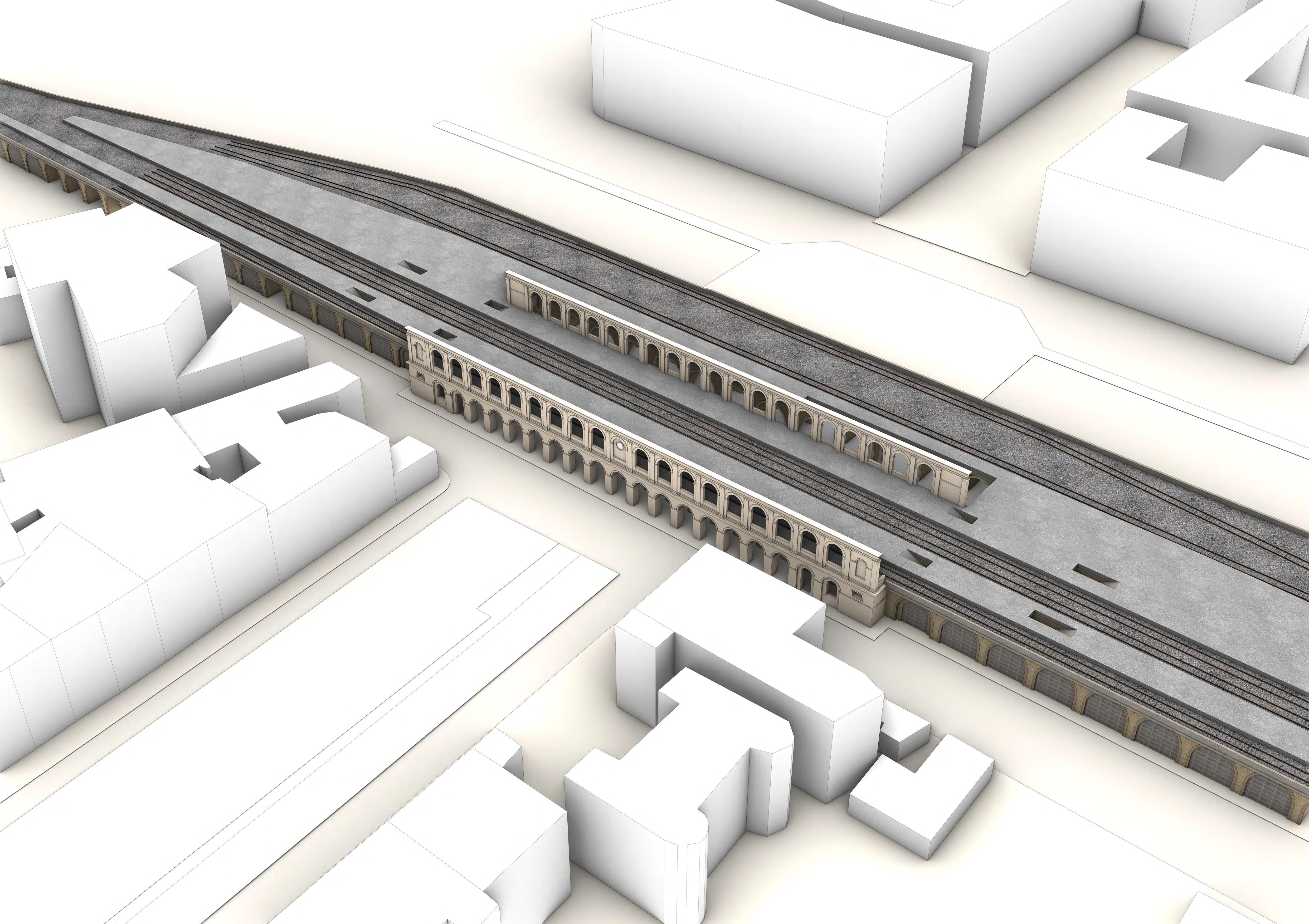
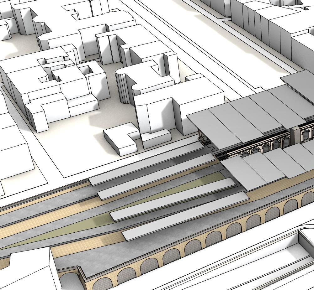
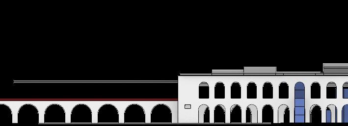
The station was built in 1844 by Paulin Talabot to respond to early railway developments. The roof was replaced with the current concrete shells in 1947. Its six platforms serve merchandise, regional and high-speed passenger trains.
View from Above
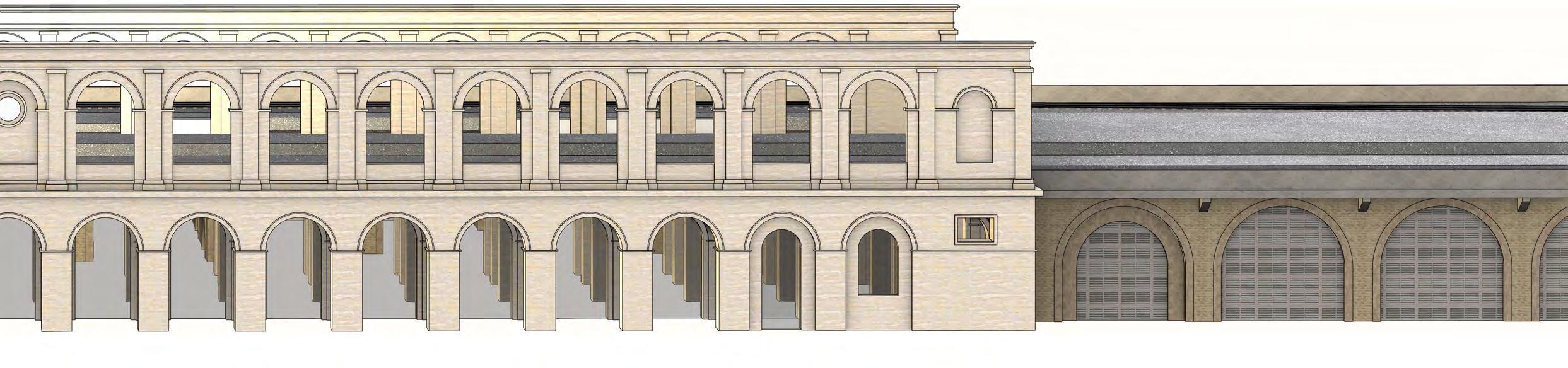
The façade is centred on the Feuchères Avenue, which is extended by the Avenue de la Méditerranée behind the station.
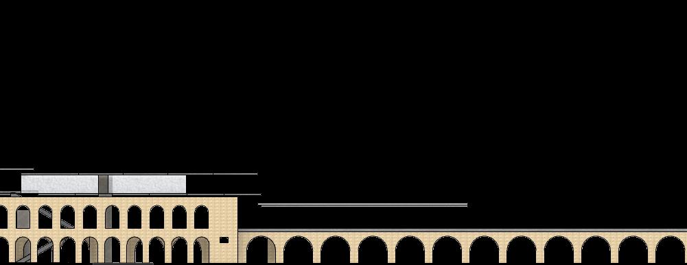
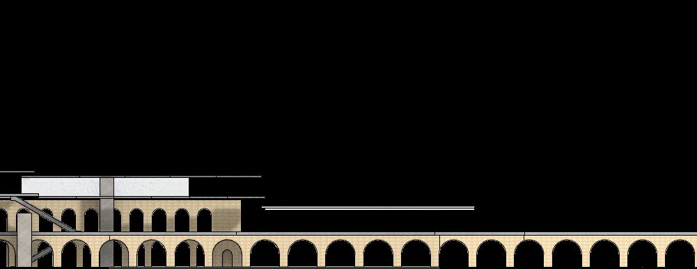
Elevation View
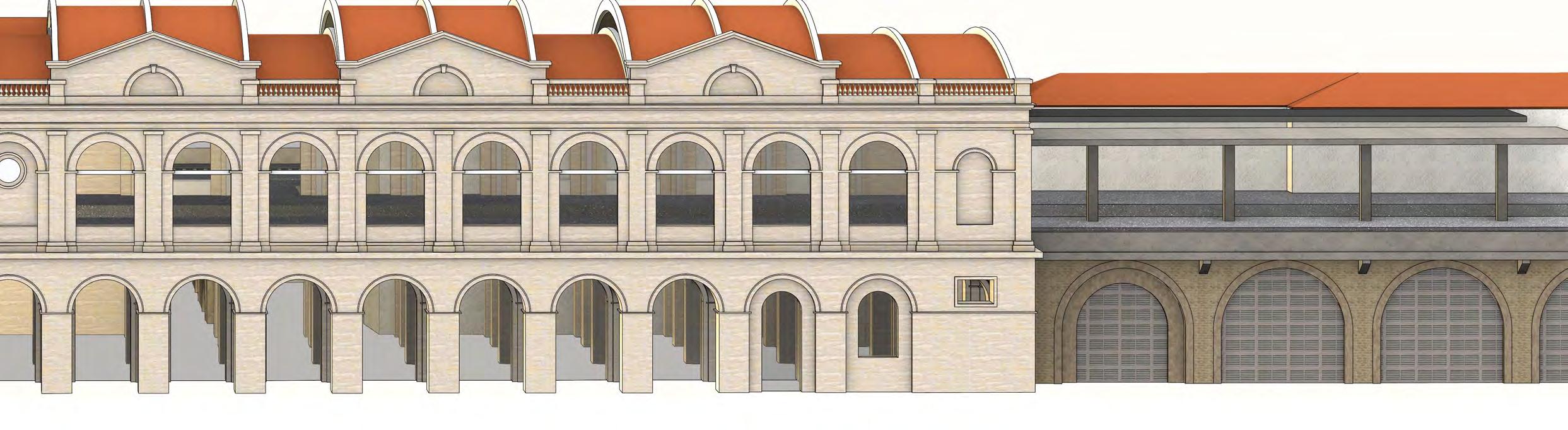
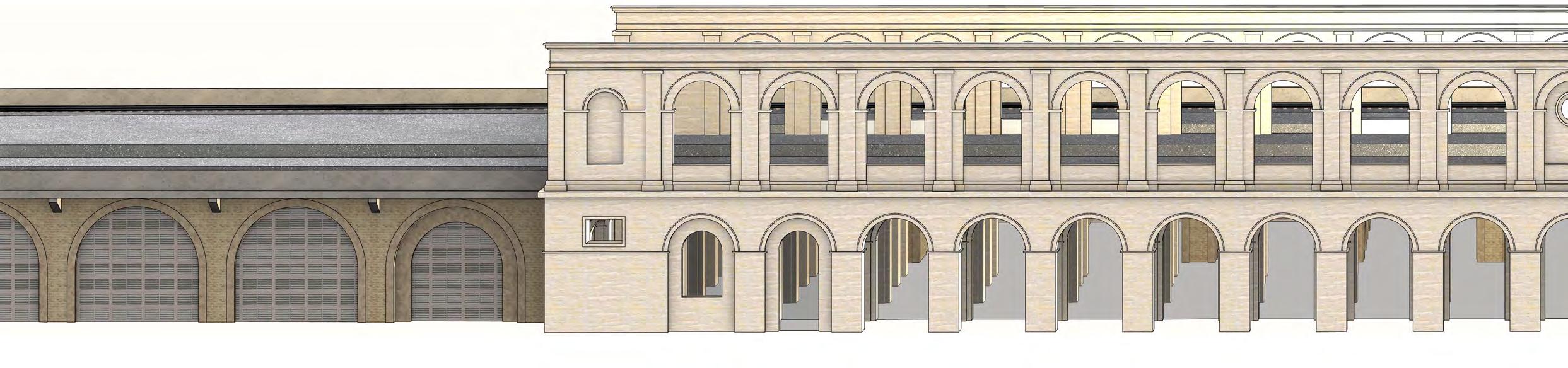
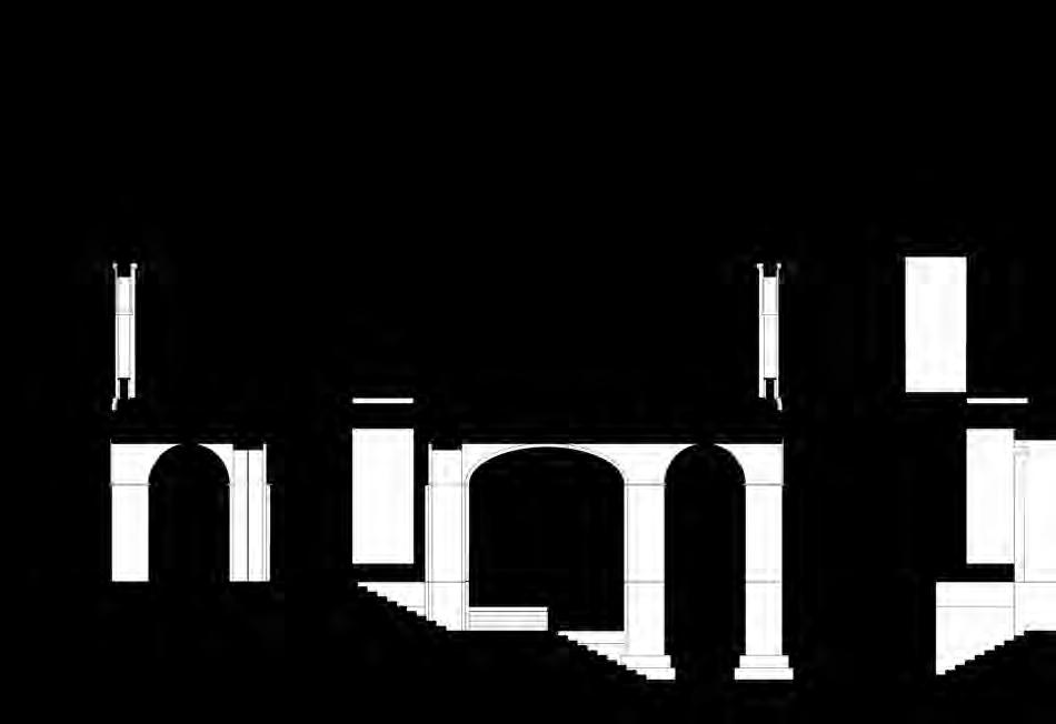
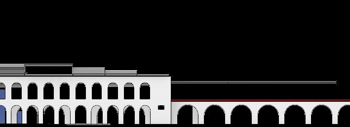
The façade consists in 21 arch bays refer back to the Roman arenas in the city.
Train Station - Retained
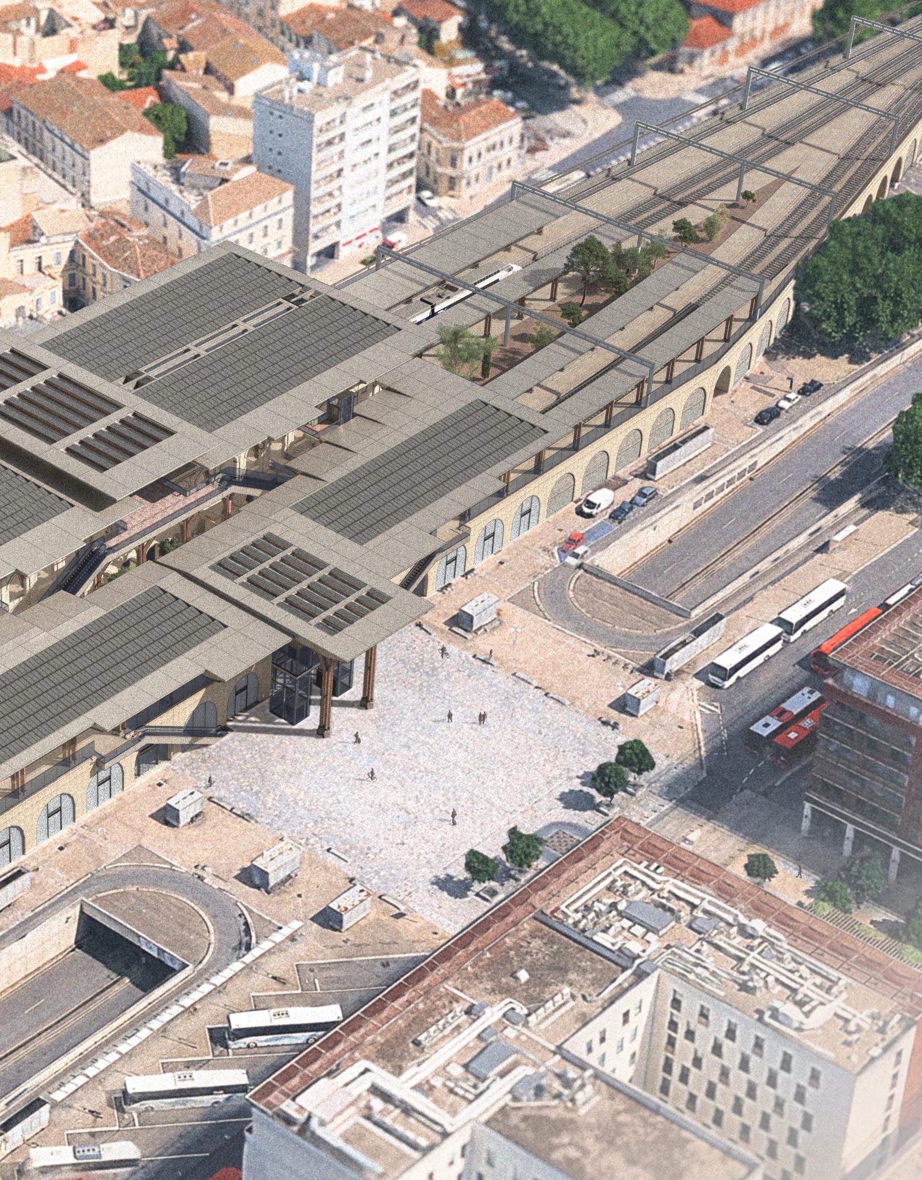
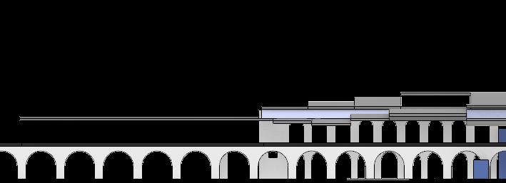
The viaduct takes a large footprint on the city centre, which building over could yield lrge areas. Removing the 1947 roof allows for a new multi-level structure, blending the new mixed-use program within the train station’s activities and linking both sides of the avenue.
Linking the roof to the Feuchères Avenue involves questions about the impact on the
View from Above
façade and the engagement with the public realm in the avenue.
The pediments, which were added later, are also removed, leaving a neat façade edge to dialogue with.
Elevation View
Program & Massing
A study of the program, the space arrangement and the general form.
Program - Zoning
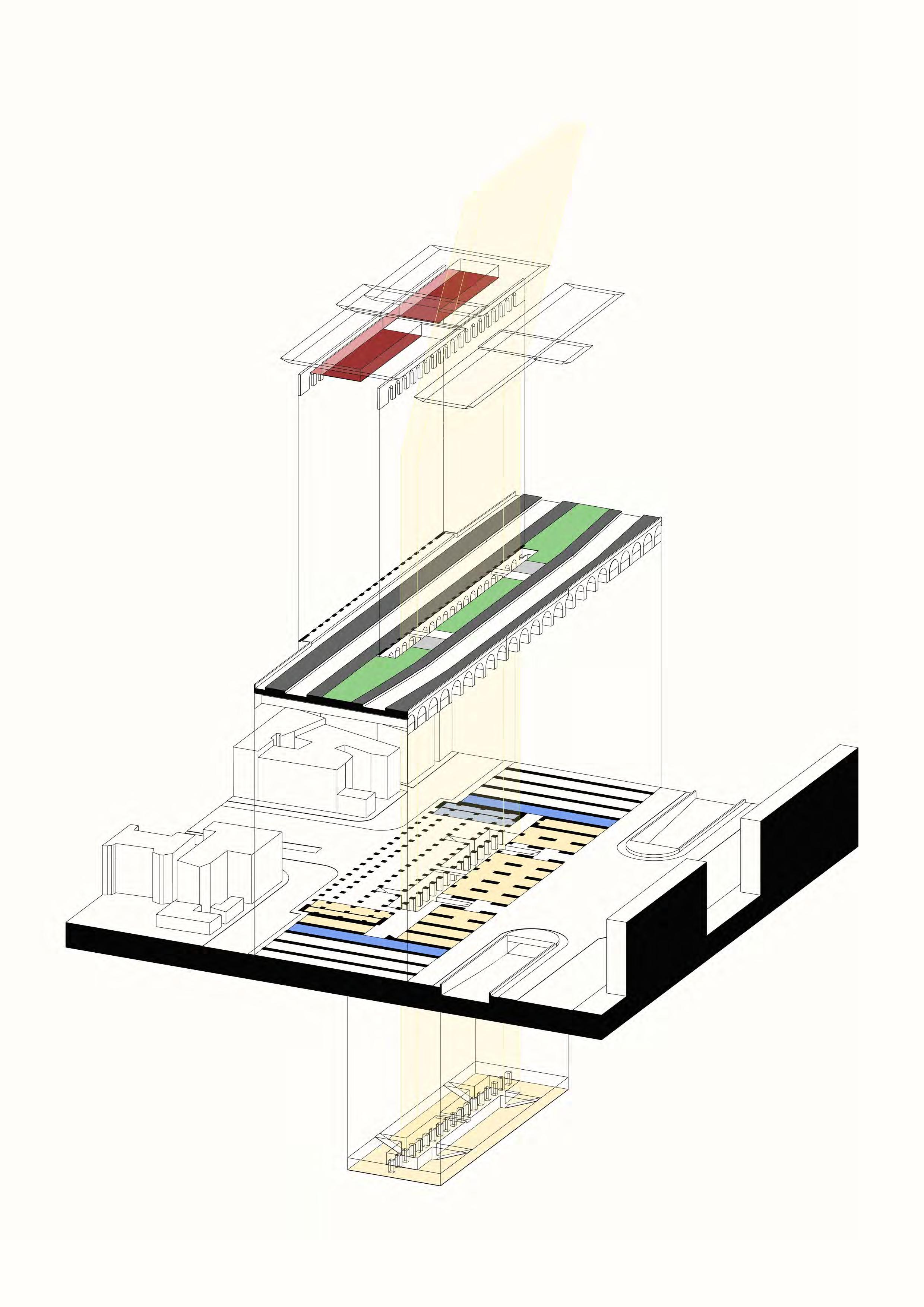
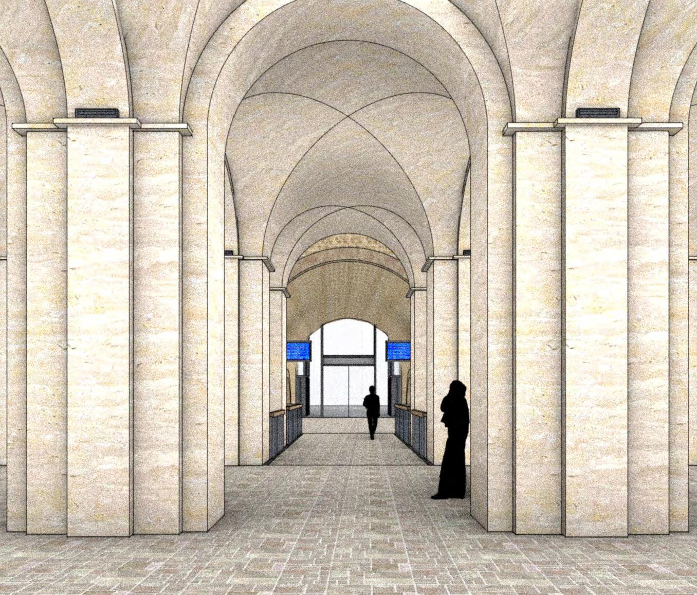
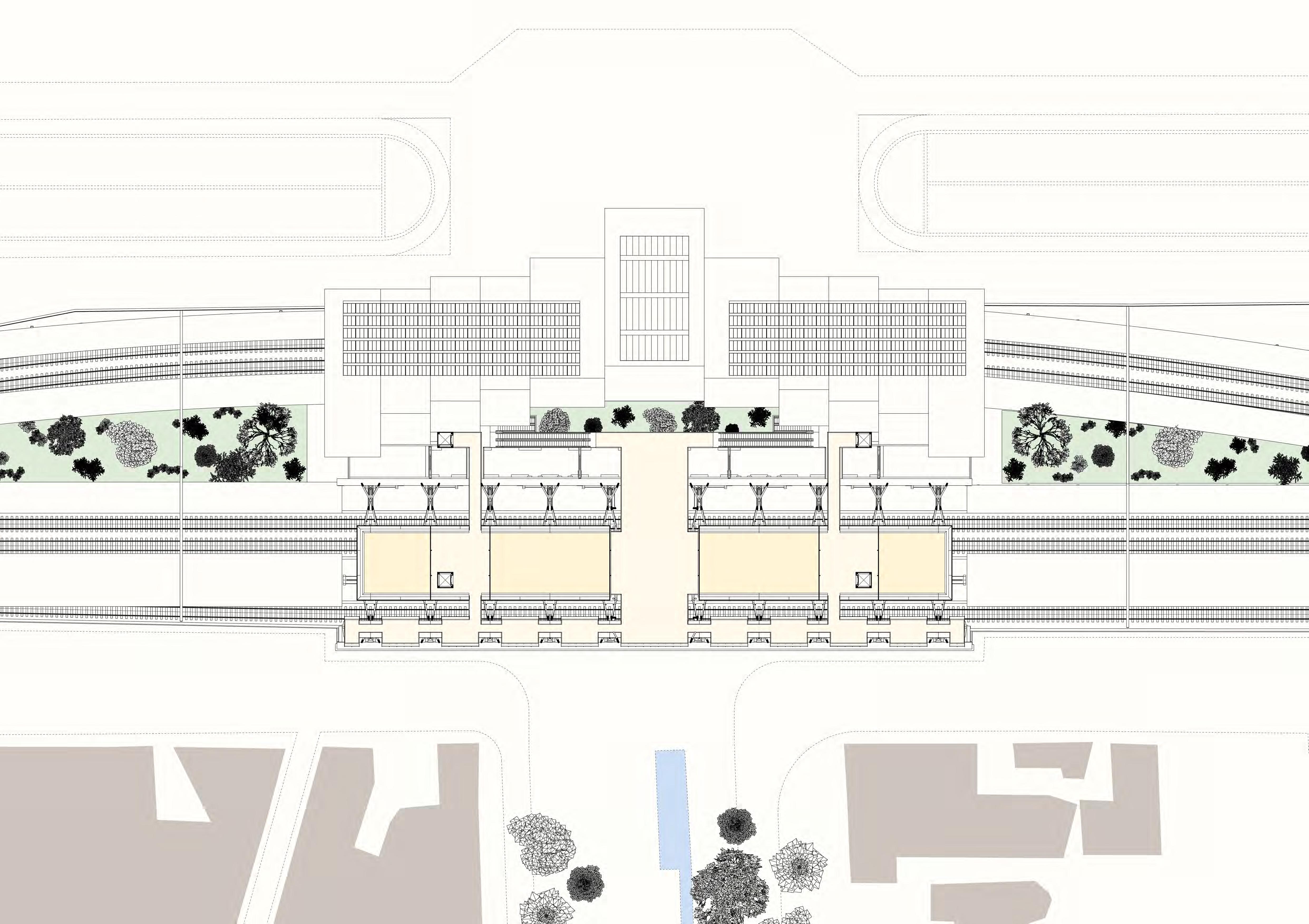
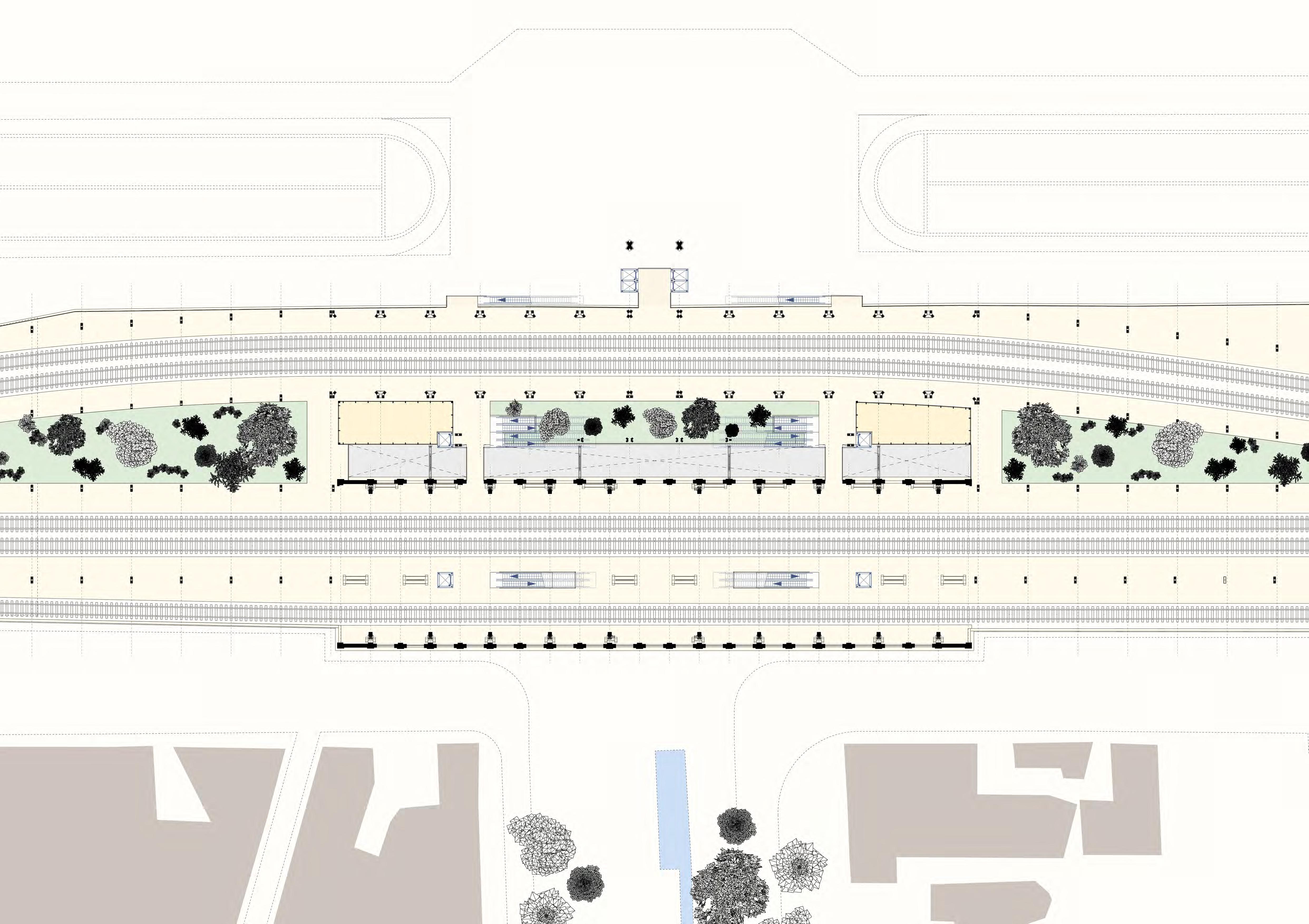
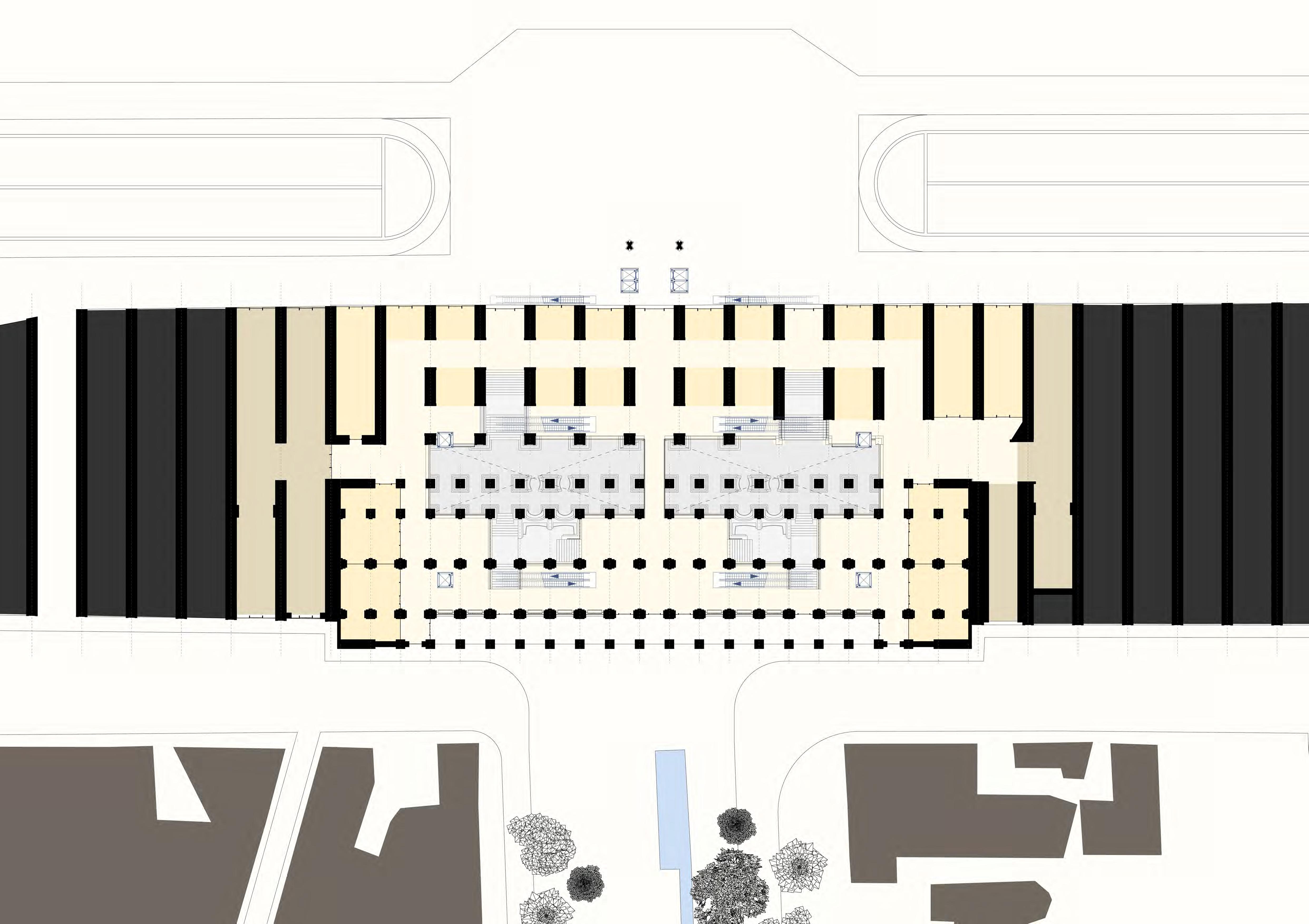
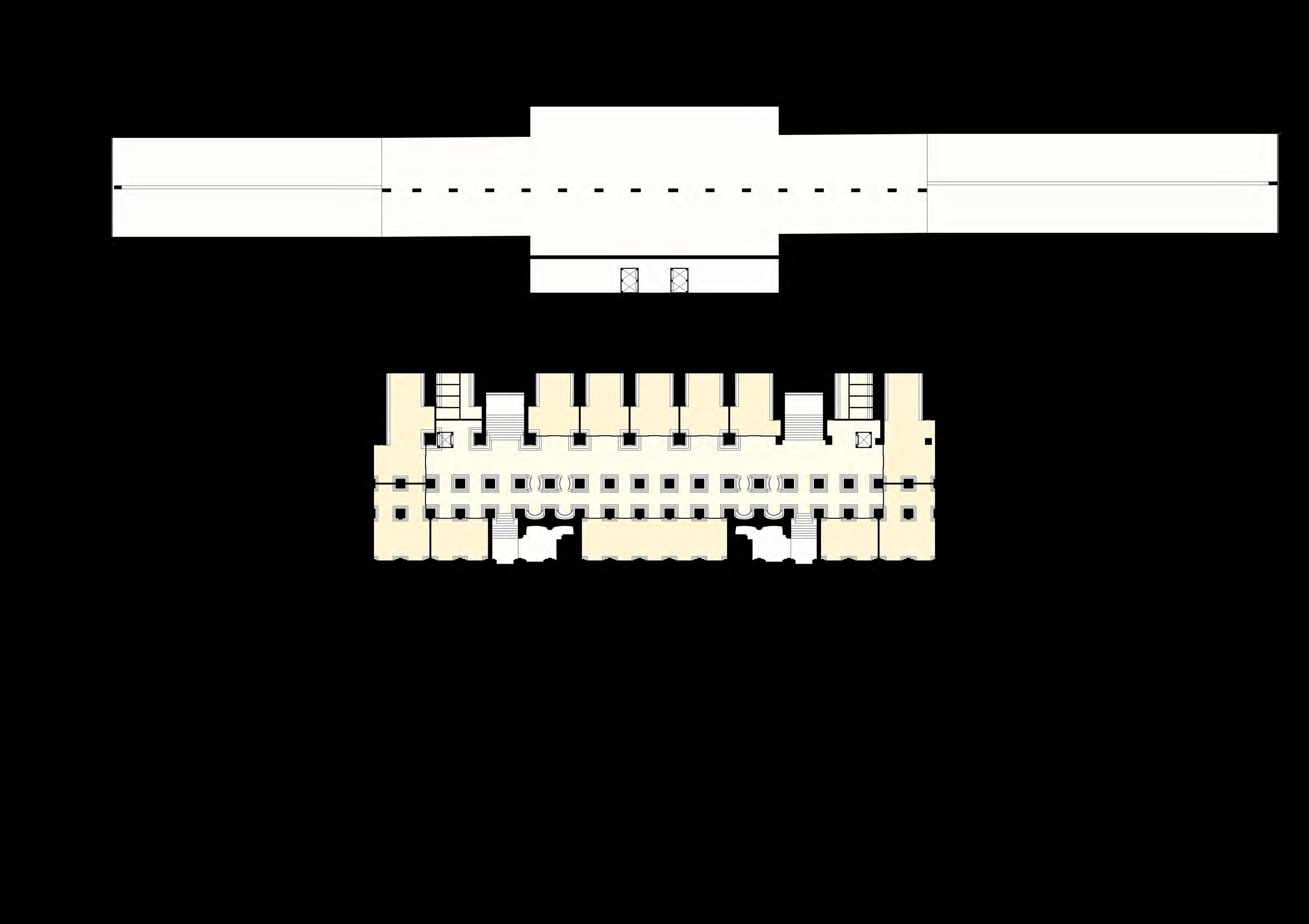
The program is clearly divided in four levels, defining their distinct function and design language. The central atrium ties the levels together, channeling light and circulation.
Level 2 - Rooftop Restaurants & Terraces
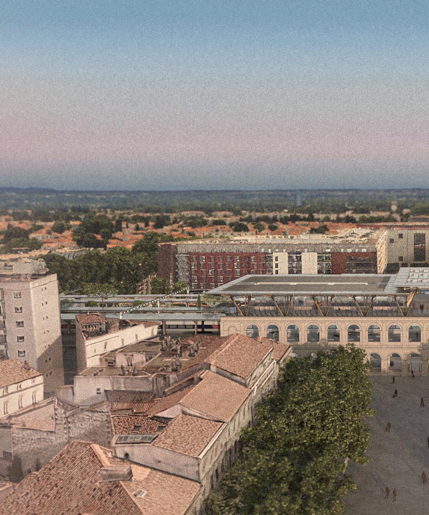
As in the Bolhao market, the restaurants look over the activity below, creating a place calm contrasting with the dynamic environment. The rooftop restaurants also offer panoramic views over the old city centre, with shaded terraces for travelers and city dwellers to restore.
Level 1 - Garden by the Platforms
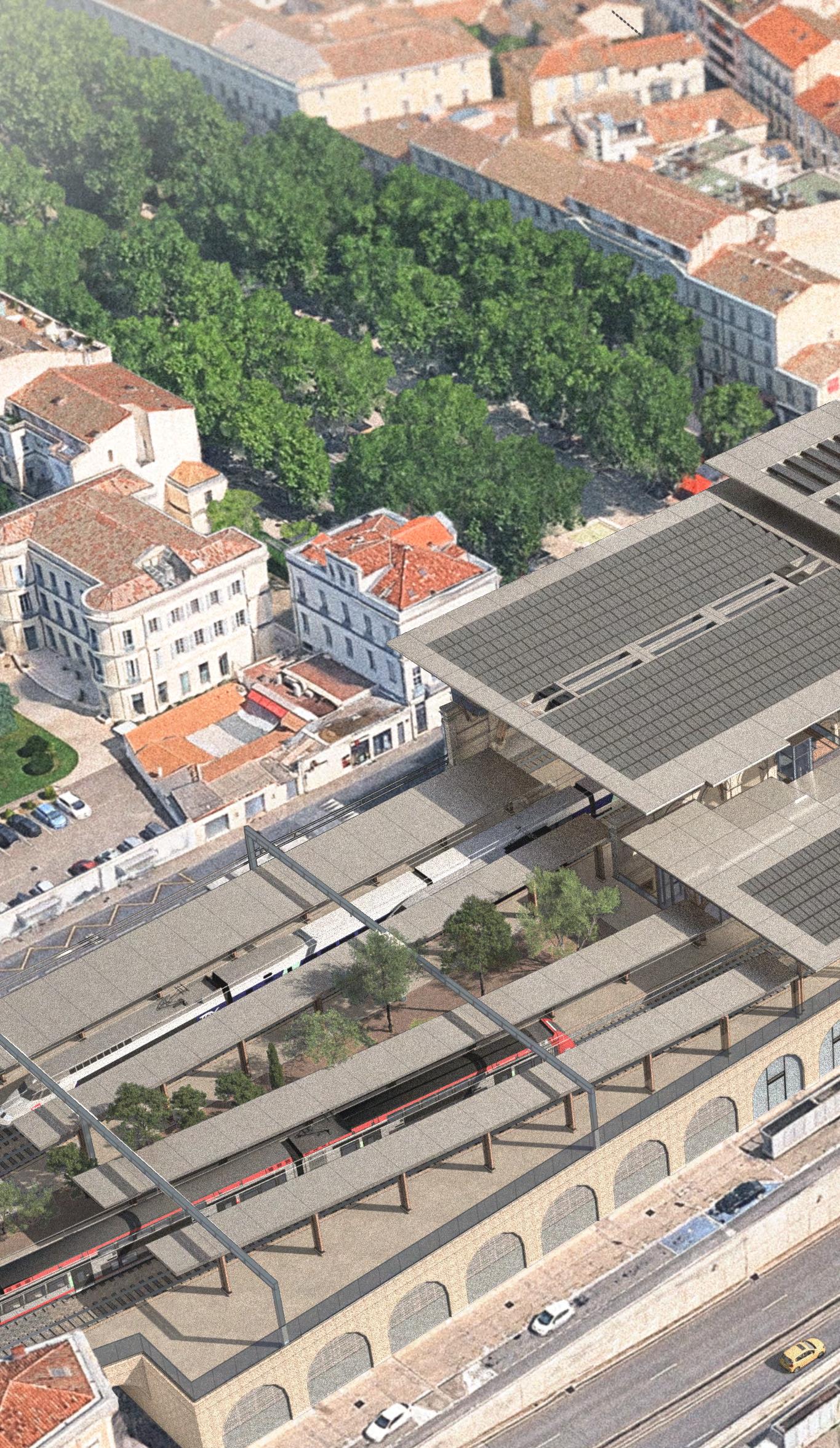
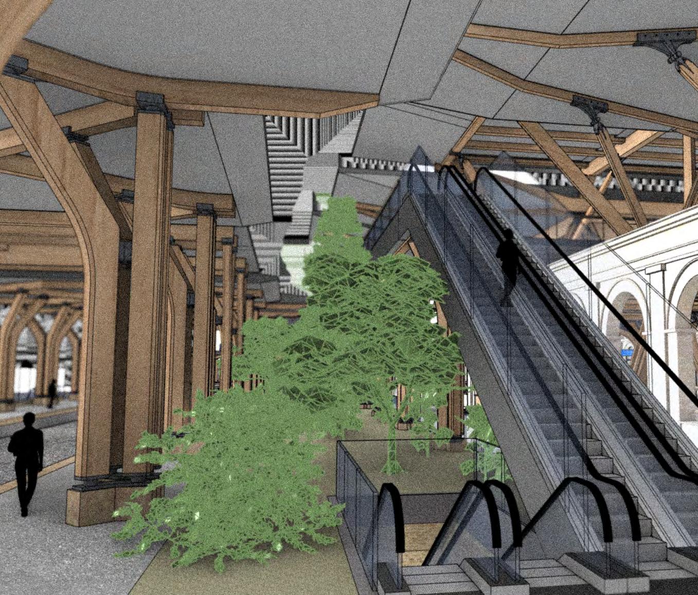
To cope with the projected 25% increase in train traffic by 2030, a 5th platform is added. Their layout is arranged so that a strip remains free next to the atrium for a garden, with access to sunlight. This is inspired by the Atocha station, where a covered garden welcomes and enchants travelers on their way. Waiting rooms interrupt the garden into 3 zones, with different landscaping strategies.
Level 0 - Entrance Hall
The ground floor of the station is an open hall which works as ahybrid space. It welcomes travelers, leadingthem to their platforms. It also channels pedestrians between each side of the station. But to activate the space more, commercial spaces and the station’s administration are set on the grid of vaults. To develop the station’s light mobility network, bike storage is placed in barrel vaults on either end.
Level -1 - Retail Gallery
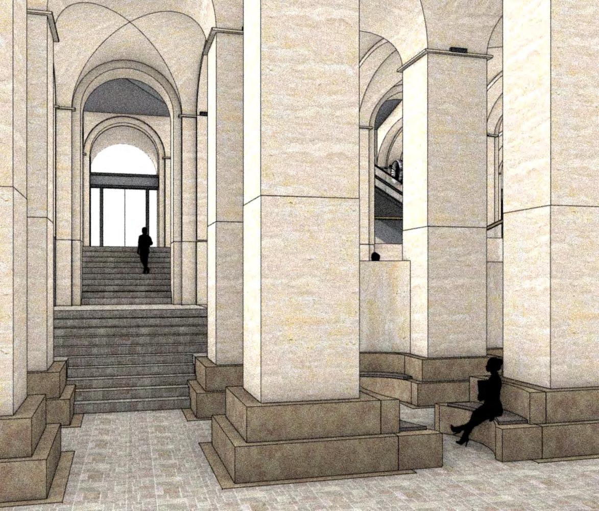
The entrance hall is excavated down to an underground level. The pillars create an arcade gallery for shops. The station becomes a commercial hub, serving both travelers and the neighborhood.
Design Inspirations
Bolhao Market, Porto
Atocha Train Station, Madrid
St. Pancras Train Station, London
Basilica Cistern, Istanbul
Massing - Railway Layout
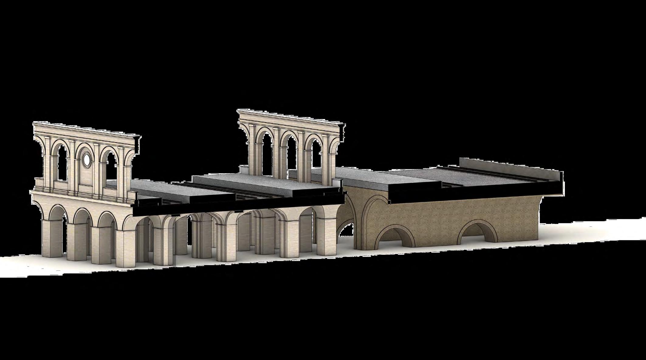
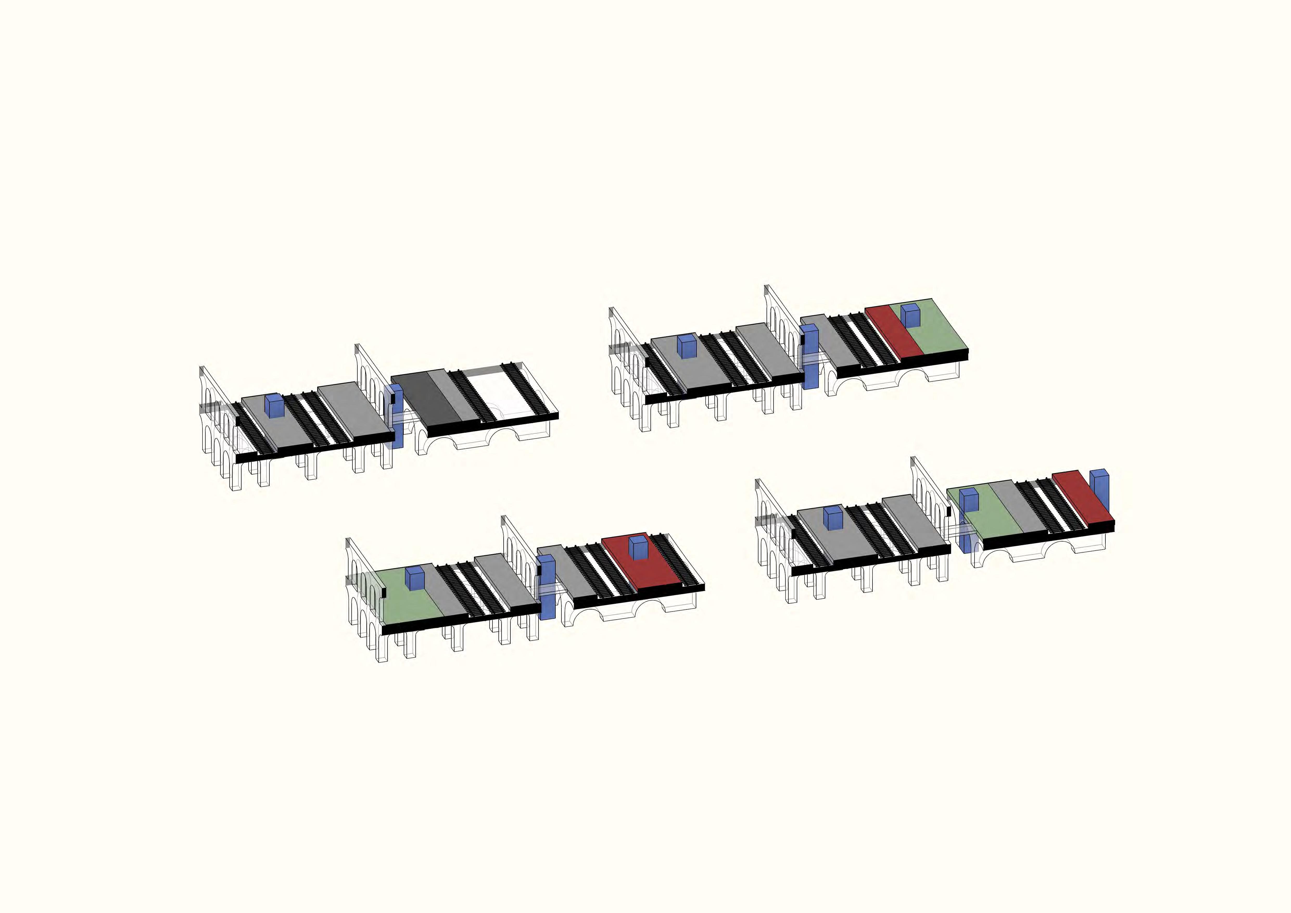
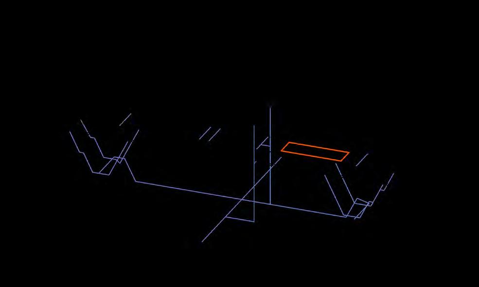
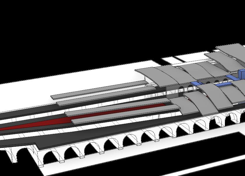
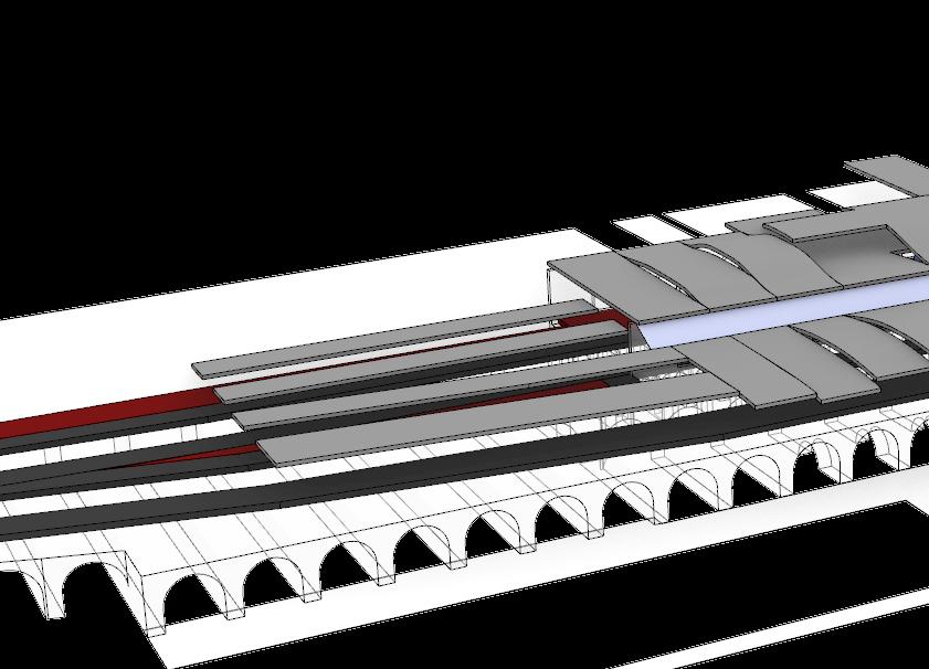
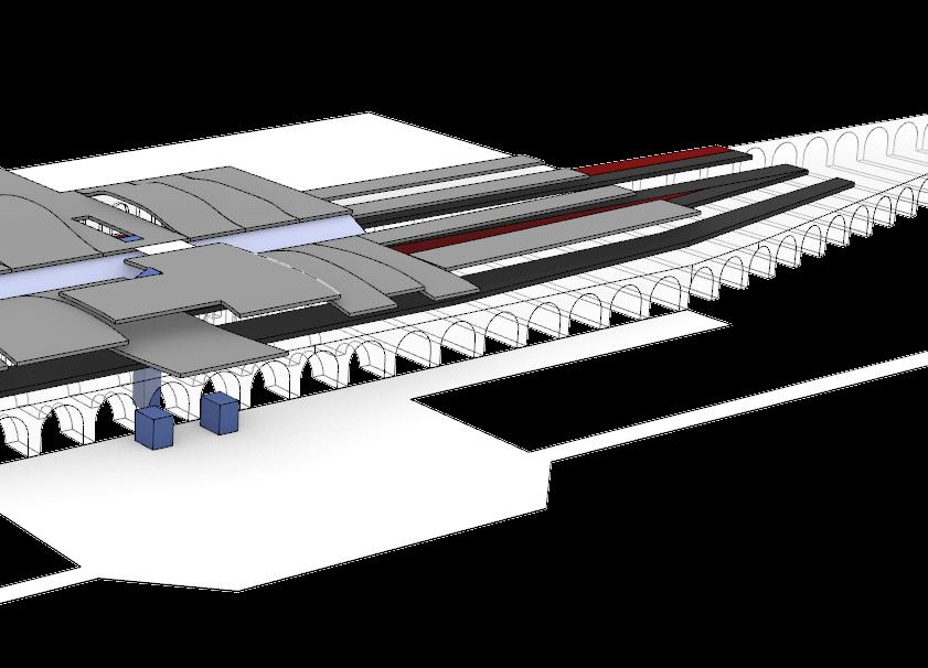
The existing station and viaduct are analysed for the capacity of platforms and railway tracks in relation to vertical transportation (in blue) and additional program (in red). Iterations explore the arrangement of 5 platforms on the existing infrastructure.
Existing layout
3 platforms are located in the station building, 1 on the viaduct. the 5th set of tracks is for trains crossing through the station, i.e. freight, which is not necessary since the Nîmes Pont-du-Gard bypass.
Iteration 2
The platforms inside the station remain the same. While the 2 platforms on the viaduct are pushed towards the inside, concentrating the platforms together. The space for the new program can now spill out towards new construction on the South-East side.
Iteration 1
The platforms inside the station are shifted for more clearance on the platforms. The viaduct have the 2 other platforms pushed towards the outside to expand the additional program. The train station program focuses around the atrium space.
Iteration 3
The viaduct is now filled with 3 platforms so that more space is freed up on the North-West side. This new space can be accessible from the avenue with a footbridge.
Massing - Circulation Iterations
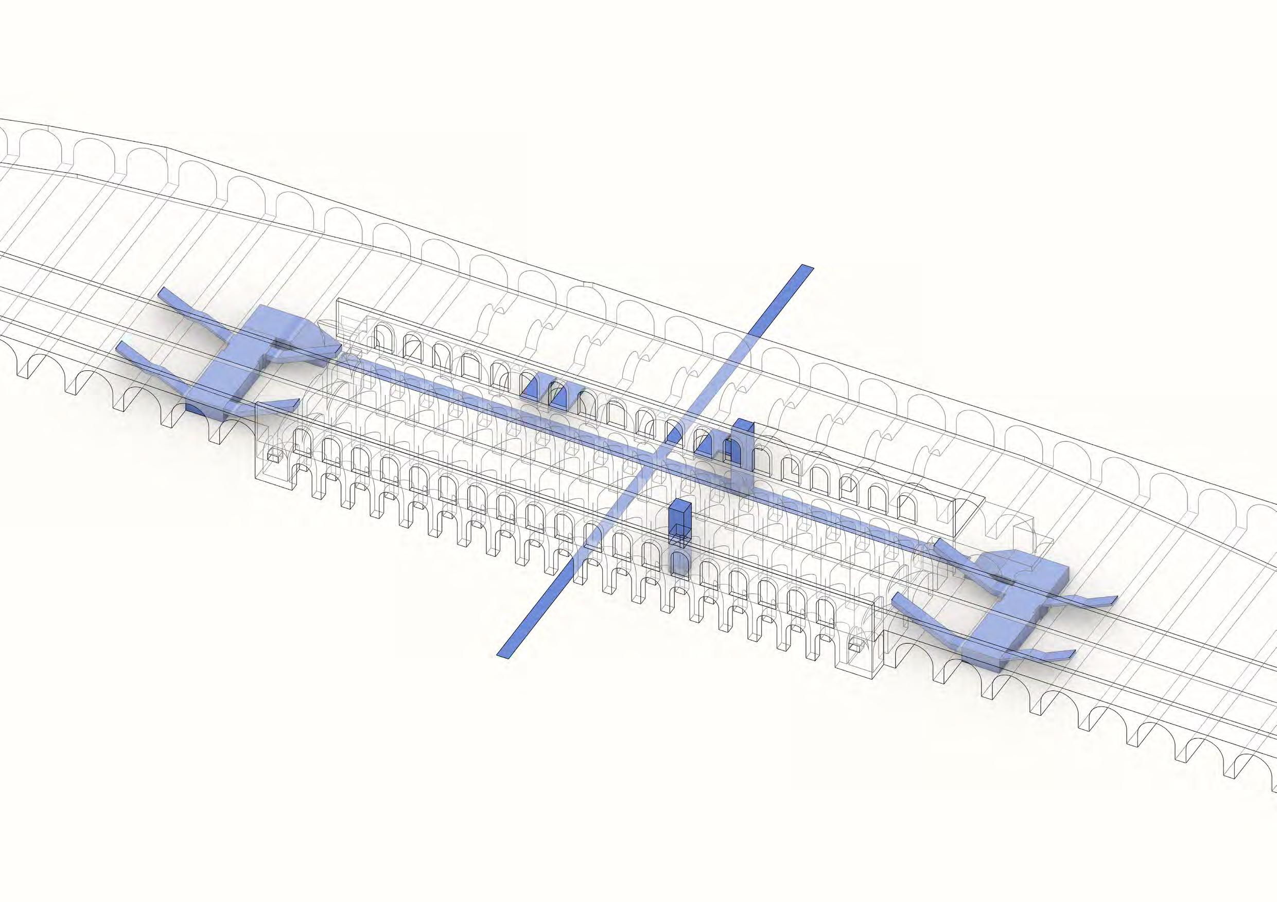
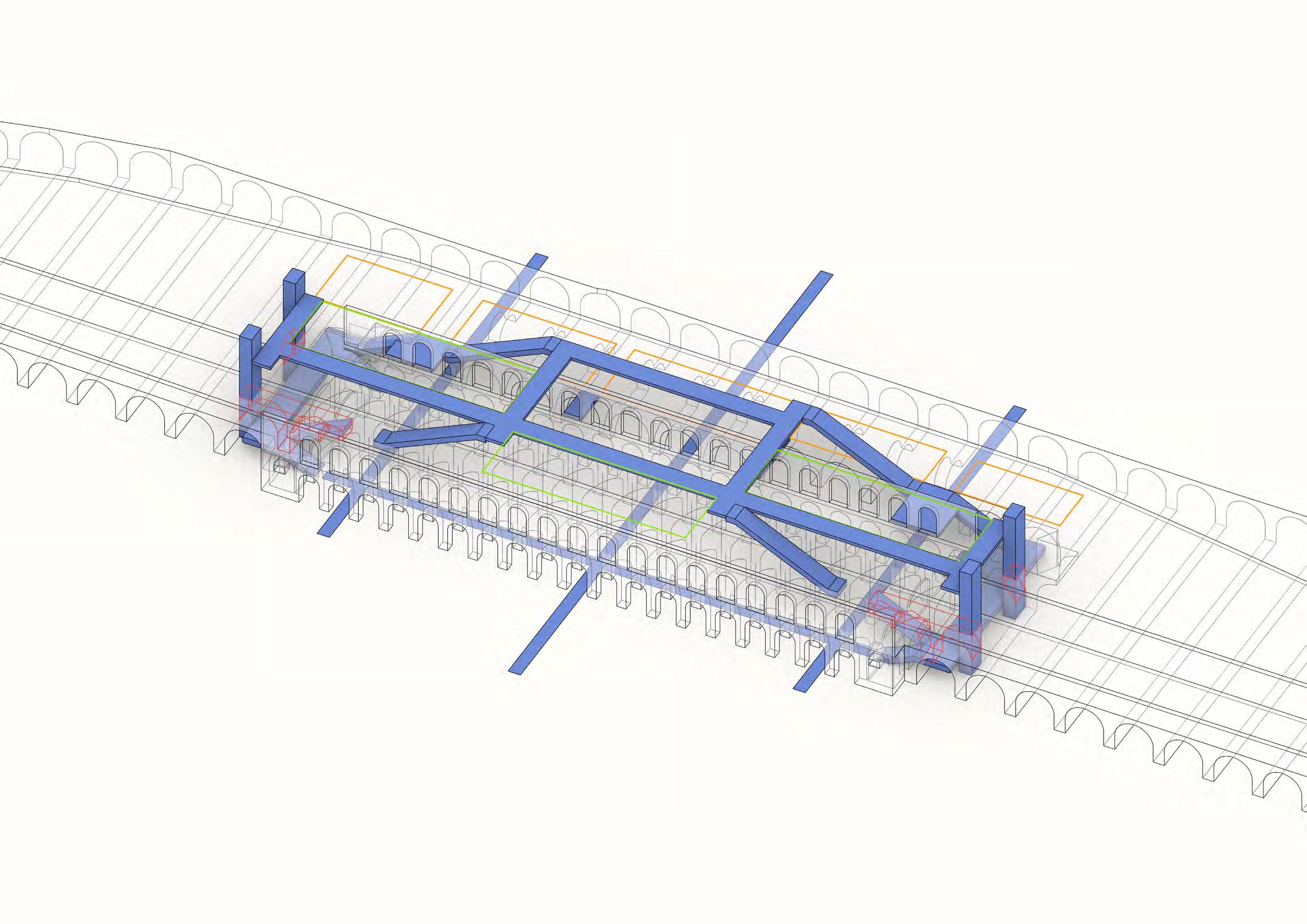
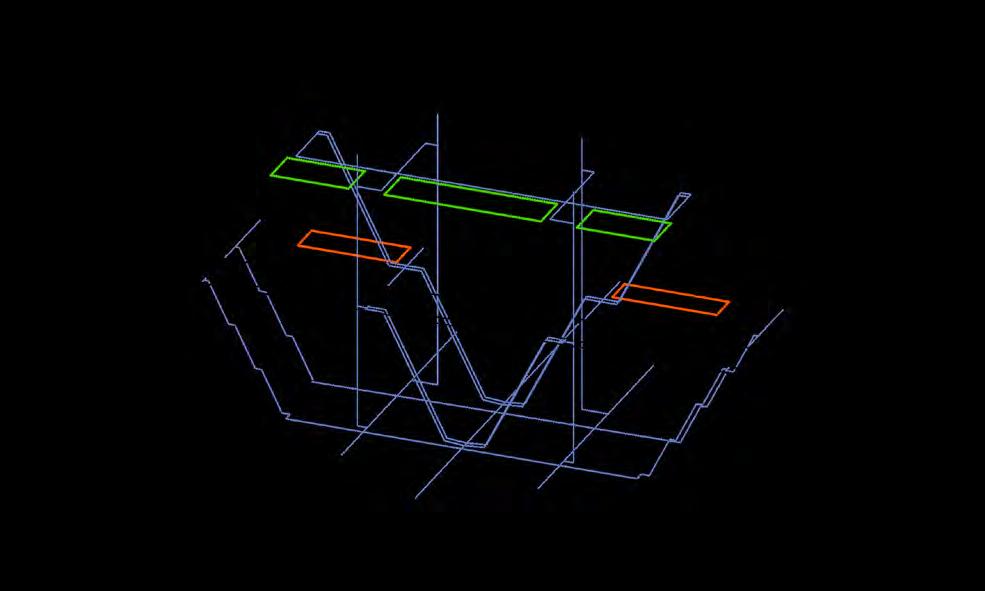
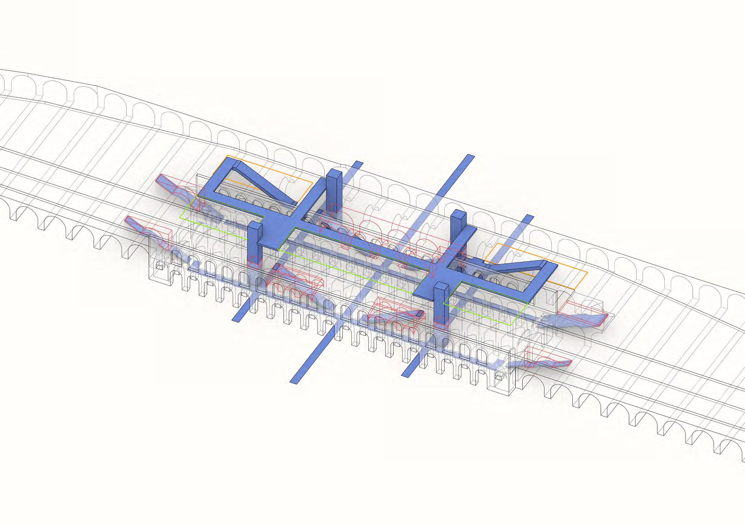
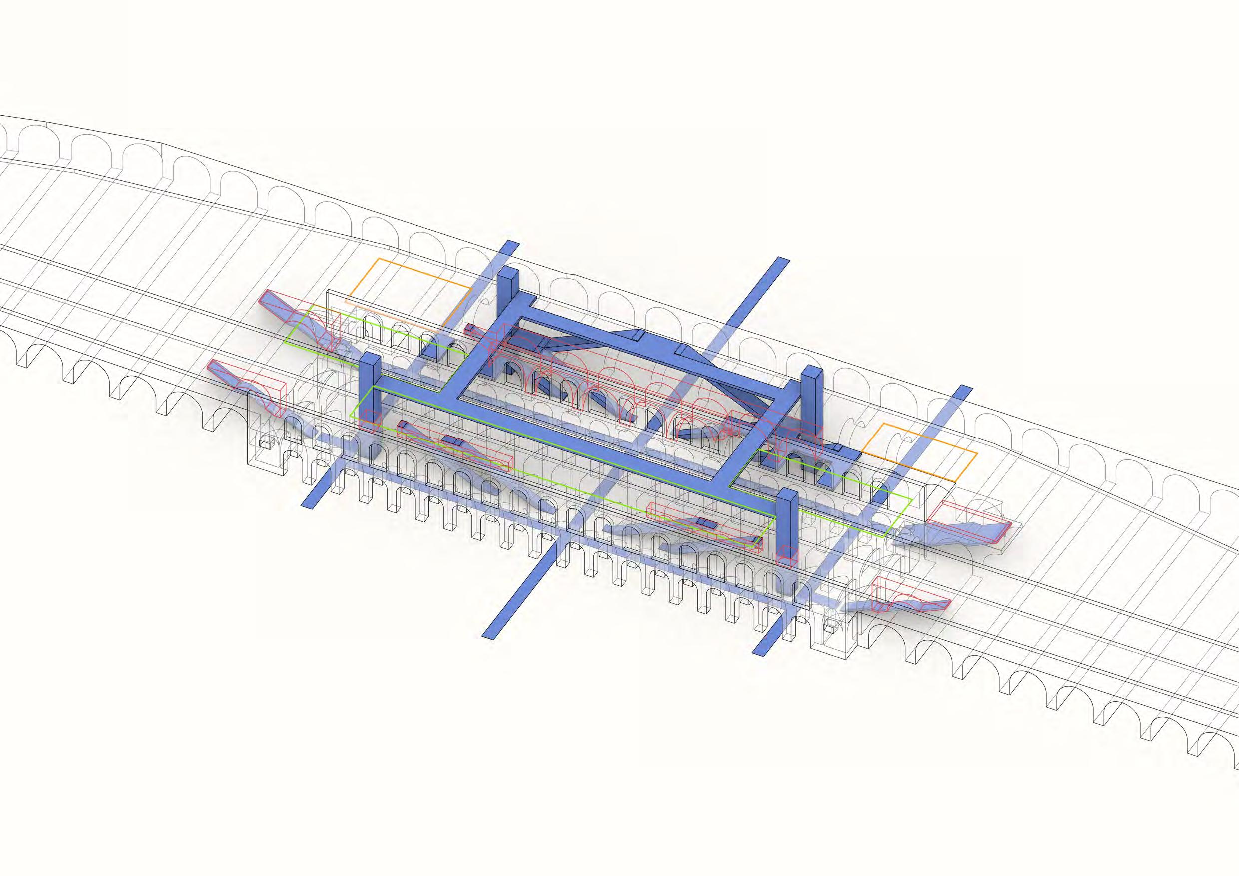
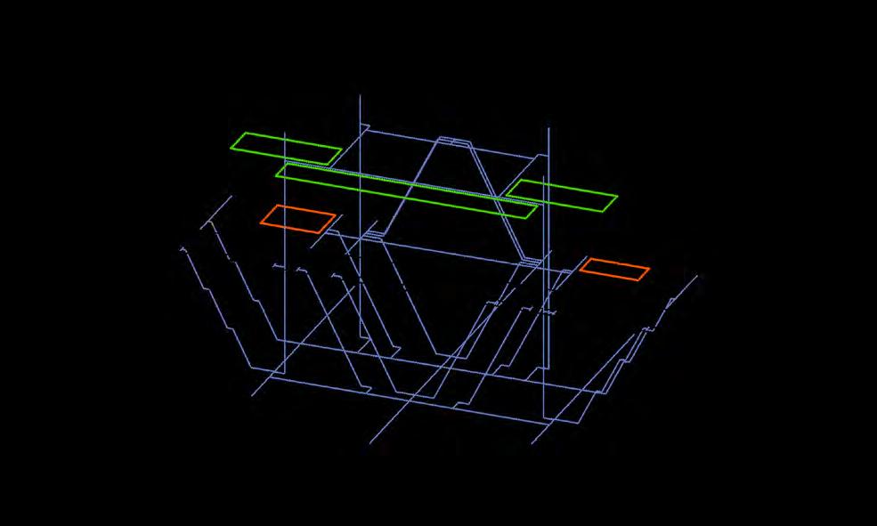
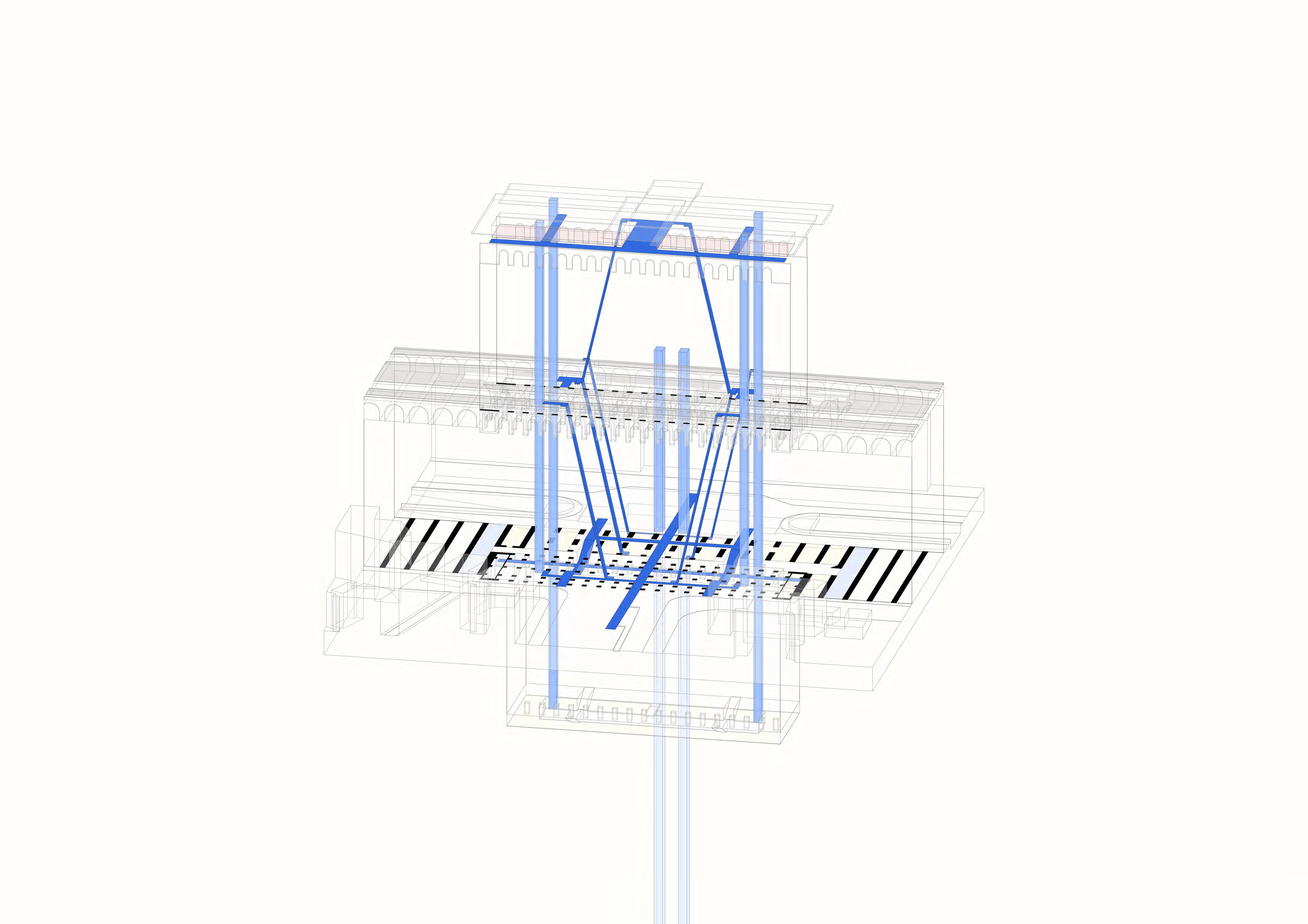
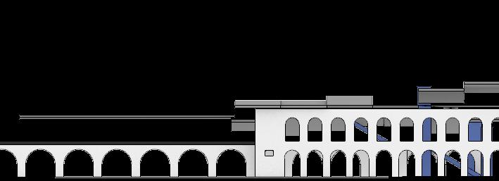
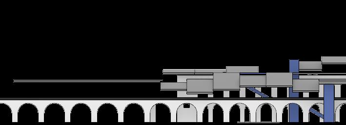
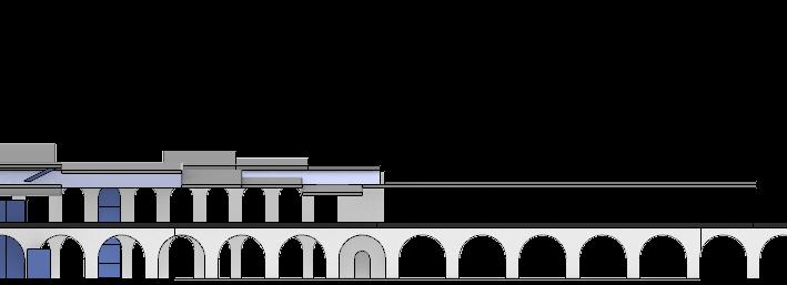
The station presents challenges with reconciling the narrow platforms, the voids and the different grids of vaults with vertical transportation between the three levels: lifts, escalators and staircases (in blue). Those elemetnts require cutouts through the stone fabric of the station and the viaduct (in red). The strategies aim for clear axes of circulation through and along the station.
Existing strategy: Winding corridors on either end
The existing circulation is far from the entrances to the station, requiring an 80 m walk beofre reaching the platform. In addition, the lifts are left are left alone in the middle, yielding a disparate circulation plan.
Iteration 1: Axes on either end
While the central axis channels pedestrians across the station, through a mixed-use ground floor, the stations’ entrances are on either end with a rearranged system of escalators and lifts. The lifts serve all the three levels to make the most of the clearnace they require. The escalators continue up to a circulation ring that articulates gardens and restauration.
Iteration 2: Central axis spreading up
The station is crossed through a central axis, with the escalators springing up from it. Staircases are added at the ends for additional options. The top floor circuit winds around the station, meeting the ground at the back. Centering the main circulation requires significant cutouts in the stone fabric, articulating old and new structures.
Iteration 3: Central axis with slimmer circulation
Major cutouts are avoided in the station’s fabric, by placing escalators one in front of the other, reducing their footprint width. Although, the viaduct at the back is perforated, leaving its internal facade as a standalone. In the end, the corridor is wide and clear.
Massing - Circulation Strategy
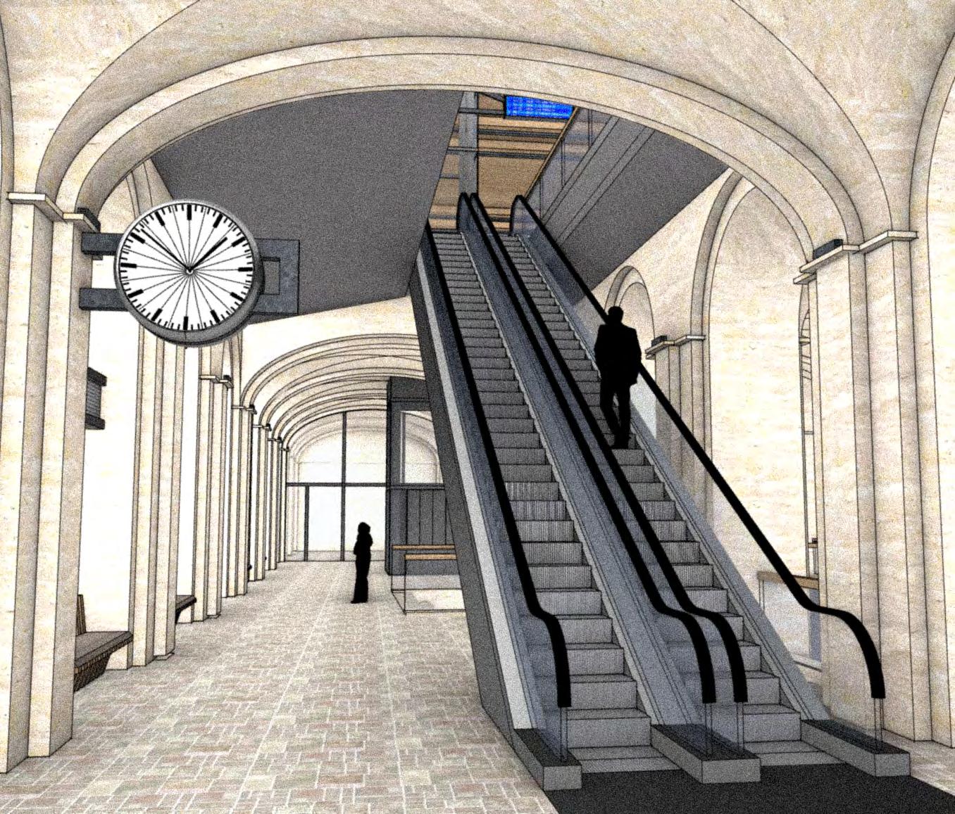
The circulation strategy is simplified for legible wayfinding and appropriate inclusive access. The central axis branches off directly into escalators that meet the lift cores further on the sides.
Simplified System
Two lift cores are placed 60 m appart, leaving enough clearance for escalators and central circulation.
Circulation Axes
The pillars of the viaduct create porosity, leaving uninterrupted axes where the grids align. The paths then branch out to the sides for internal program.
Seamless Journey
The escalators and lifts are placed on the side of the main axes and lead straight to the platform edge, creating an efficient path for both typical and inclusive access.
Platform Width Restrictions
The platform width is set by the clearance required for a comfortable experience around the lifts and escalators.
Spread Circulation
The inclusive access through the lifts is set further away from the main axis to guarantee a calmer experience for more vulnerable people through the crowds.
Exploded Isometric View
The system is repeated for each escalators in the atrium to the extended up for quick and efficient lifts are extended up for platform
Massing - Iteration 1
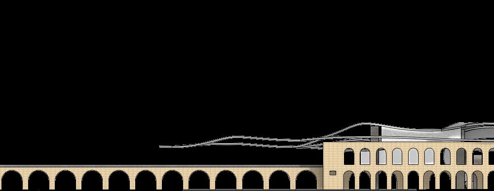
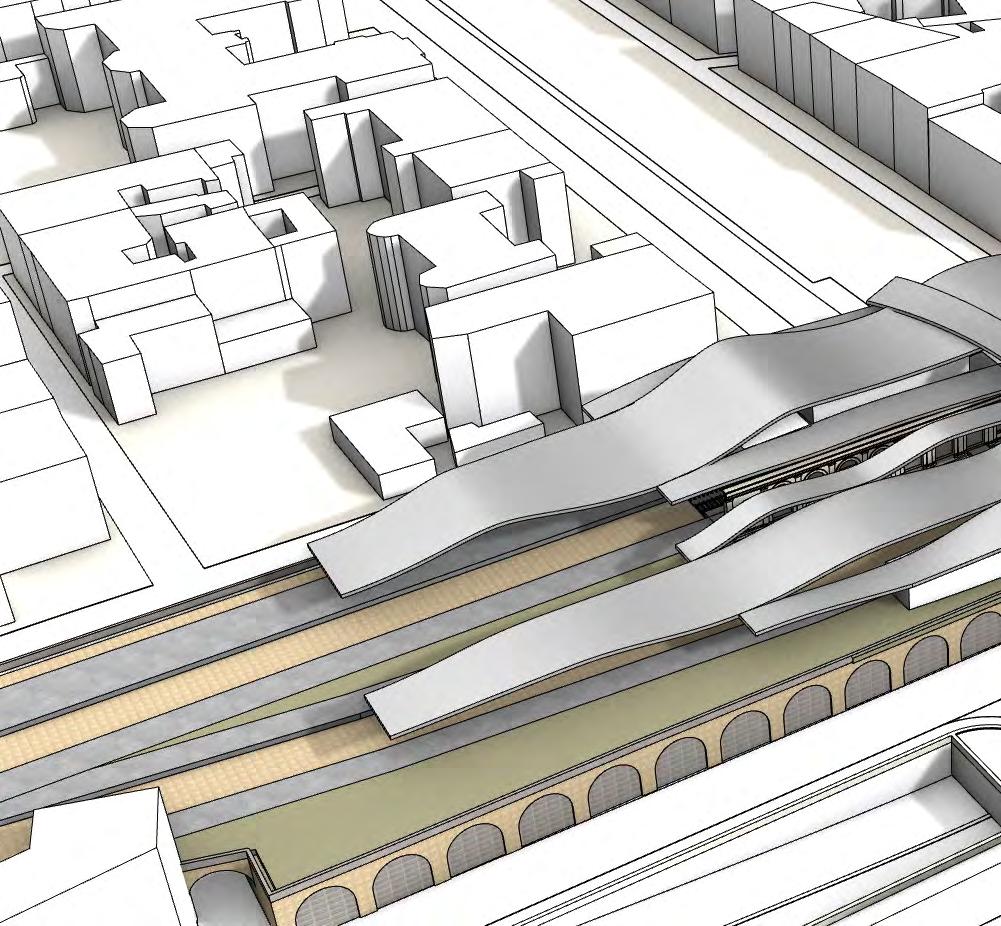
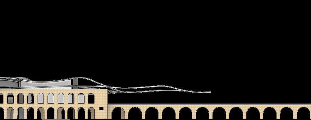
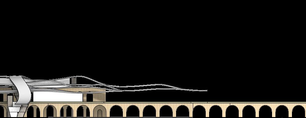
Ribbons flow along the train tracks. The ondulations contrast lightness with the mass of the rhythmed façade.
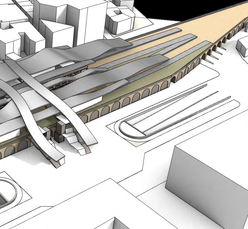
Aerial View
Cross ribbons follow the path up to the rooftop, through the garden and station. The form creates an open atrium and invites people up.
The ribbons of the roof converge and spread to create openings for program and circulation.
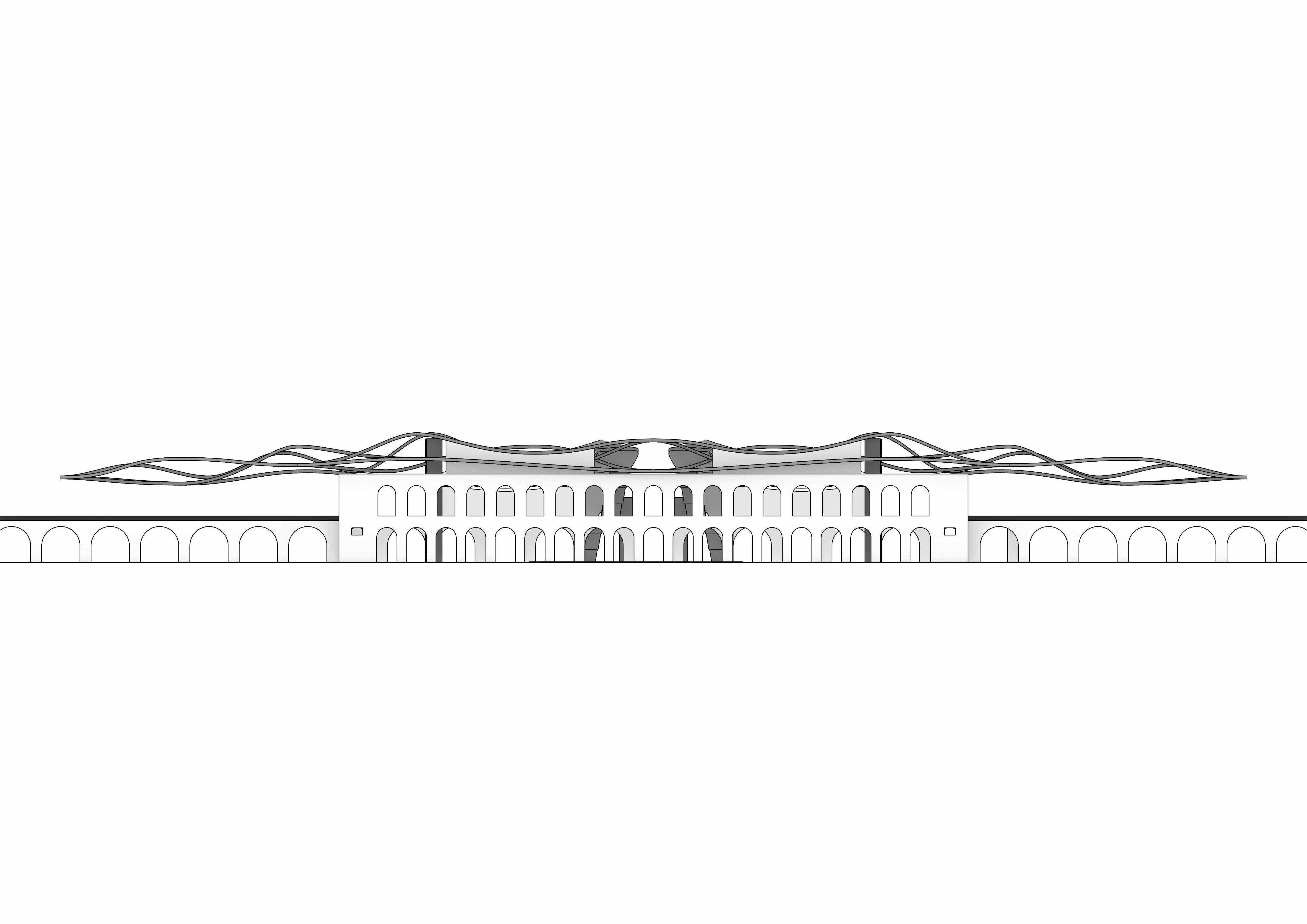
Front Elevation
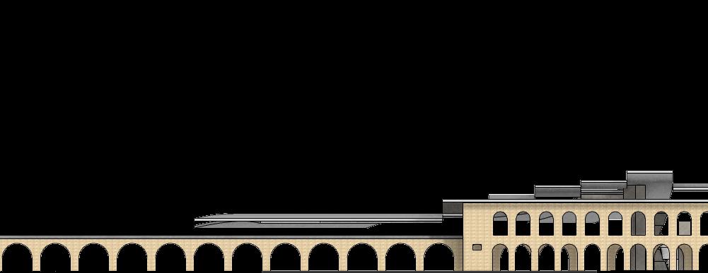
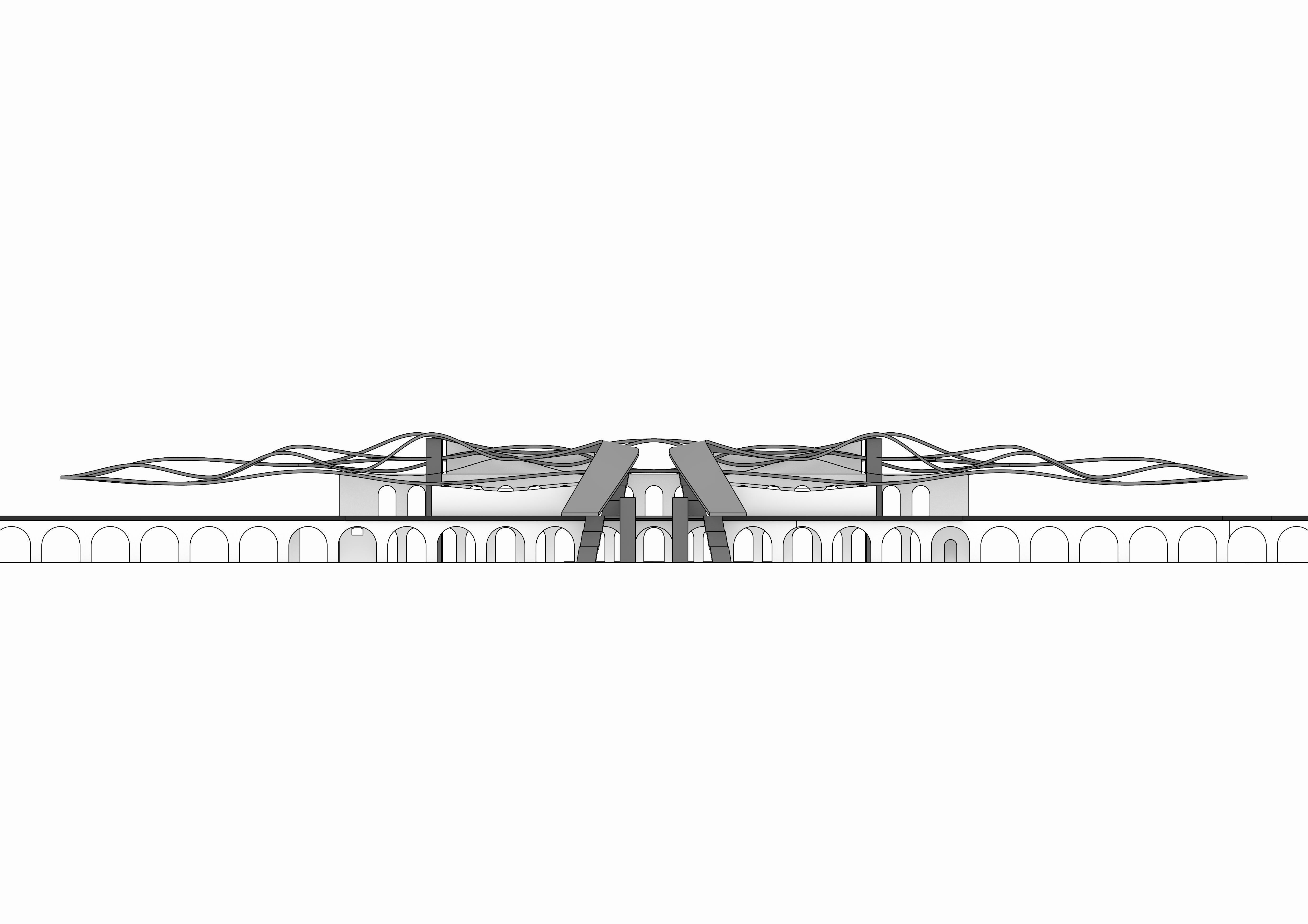
Back Elevation
The language of ribbons becomes proeminent on the back façade, as their slight descent highlights them individually.
Massing - Iteration 2
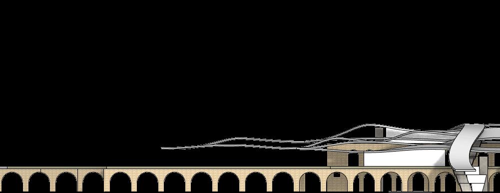
Ribbons flow across the train tracks. They step down on both sides and open up in the middle to highlight the entrance.
Aerial View
Cross ribbons follow the path up to the rooftop, through the garden and station. The form creates an open atrium and invites people up.
The
of the
converge and spread to create openings for program and circulation.
Front Elevation
ribbons
roof
Back Elevation
The language of ribbons becomes proeminent on the back façade, as their slight descent highlights them individually.
Massing - Final Iteration
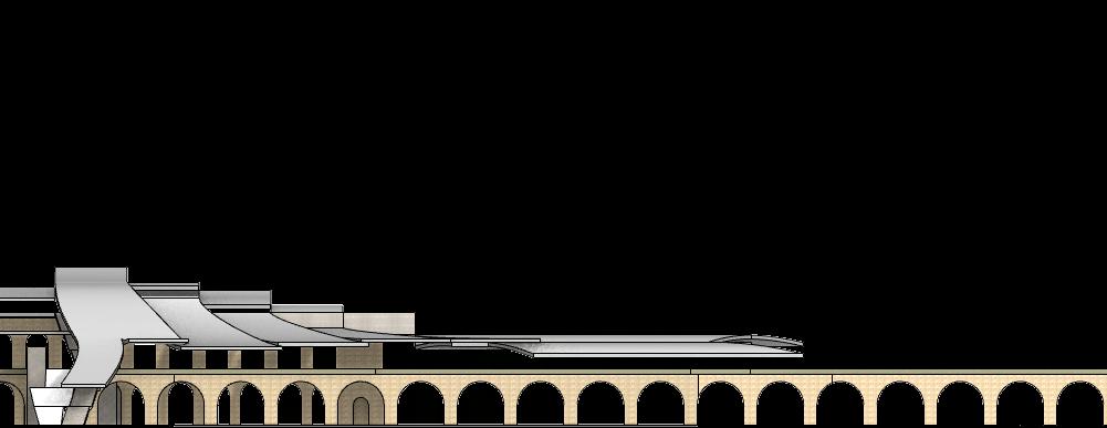
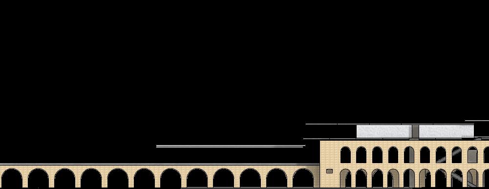
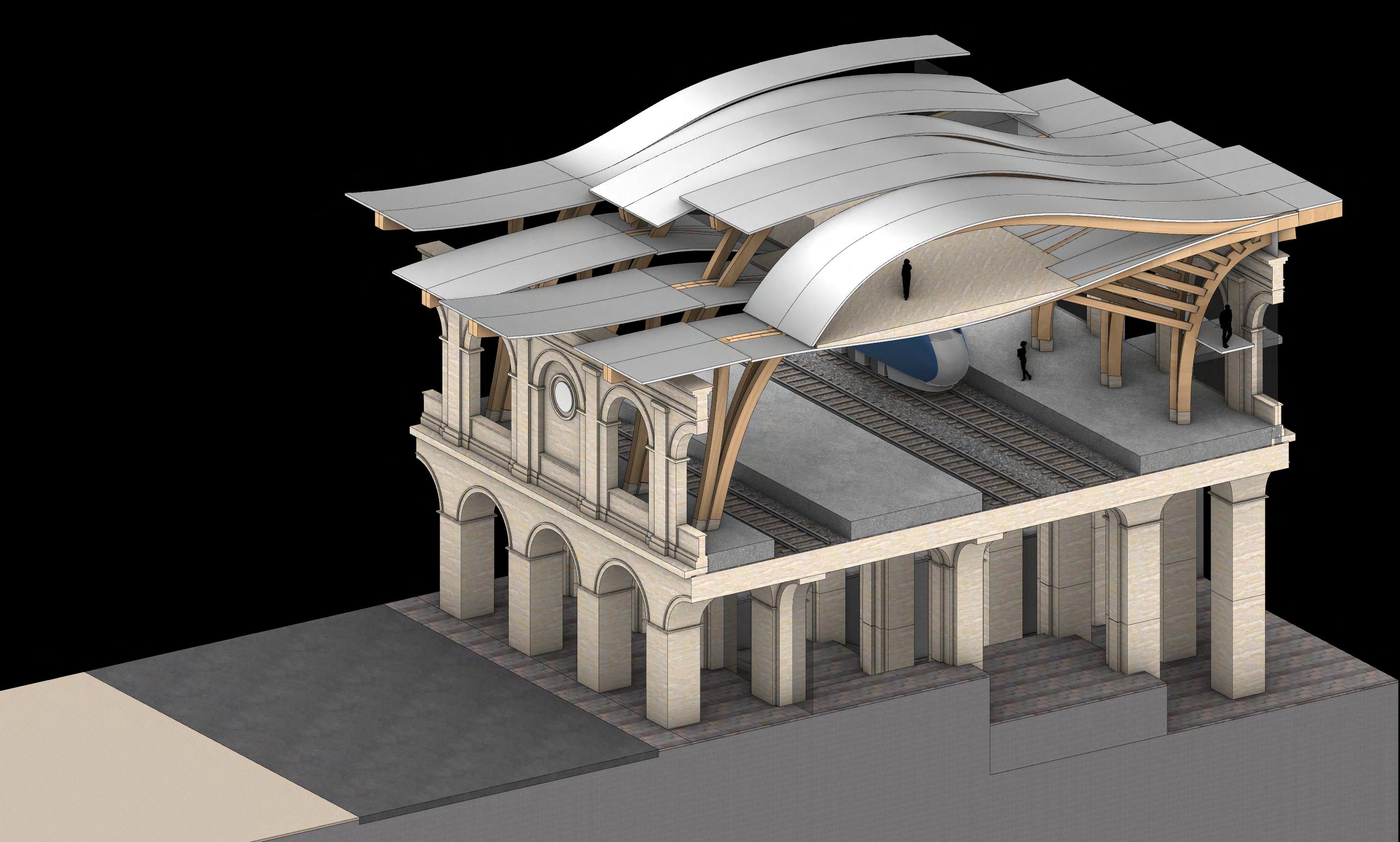
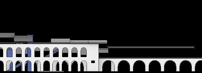
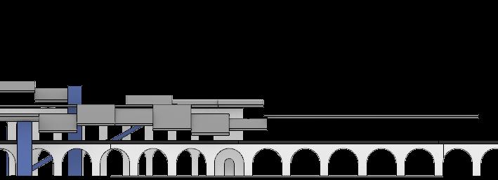
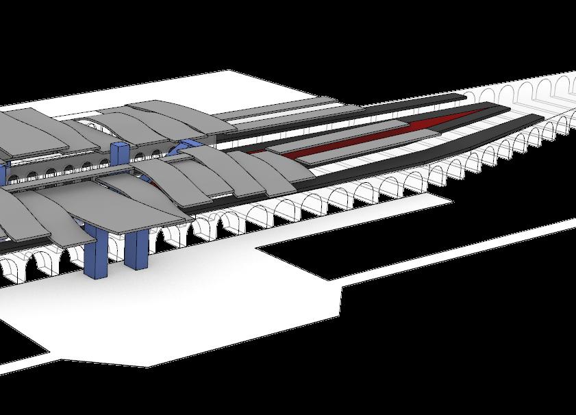
The roof form is rationalised into two flat roofs with fringes along the central atrium space. The roofs define a clear rectangular building footprint and have a less dominant effect over the façade.
Aerial View
The roof edges remain minimal on the outside and fringe out around the atrium inside to articulate the shift between the grids.
is minimally
by the
Front Elevation
The front façade
impacted
roof form, the new level appears distinctivel as a third layer on the façade. The roof shifts up at the middle to indicate the entrance.
Back Elevation
The back view becomes more open, with a simple roof as a canopy aboe the rails.
MASSING - RETAIL GALLERY
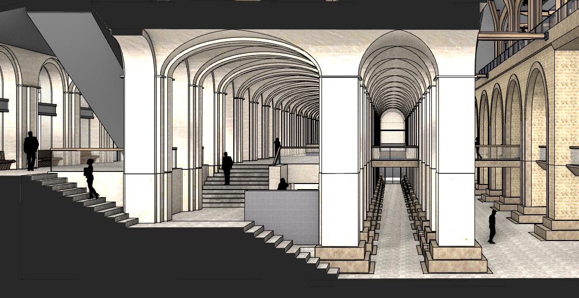
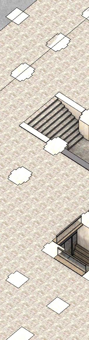
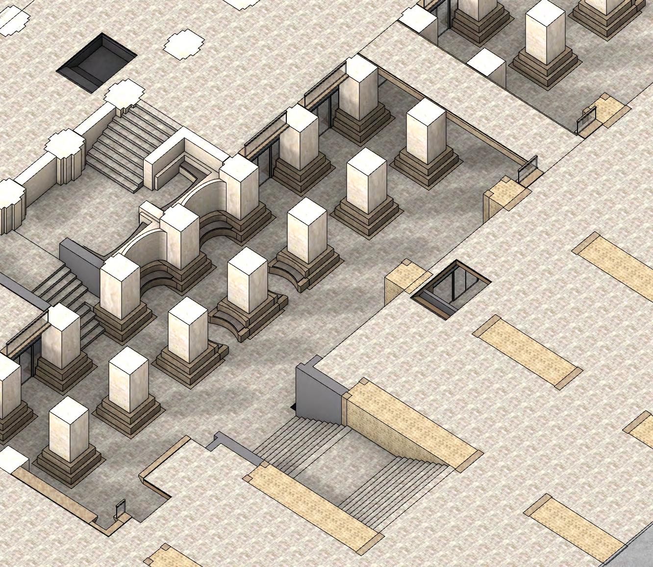
The ground floor landscape descends gradually to the level -1, through spread out flights of stairs and wide landings. Shoppers and travelers can take a break at the landings, between their activities.
The landings were designed to create the most efficient journeys and to offer pockets of privacy within the arcade.
Short Section
The pillars gain in height as the space opens up more towards the atrium, creating a cathedral-esque arcade.
Long Section
The stairs and landings integrate within the grid of existing vaults. Both façades on level -1 have their run of stores, only interrupted by the circulation.
Isometric View
Atrium - Daylighting Strategy
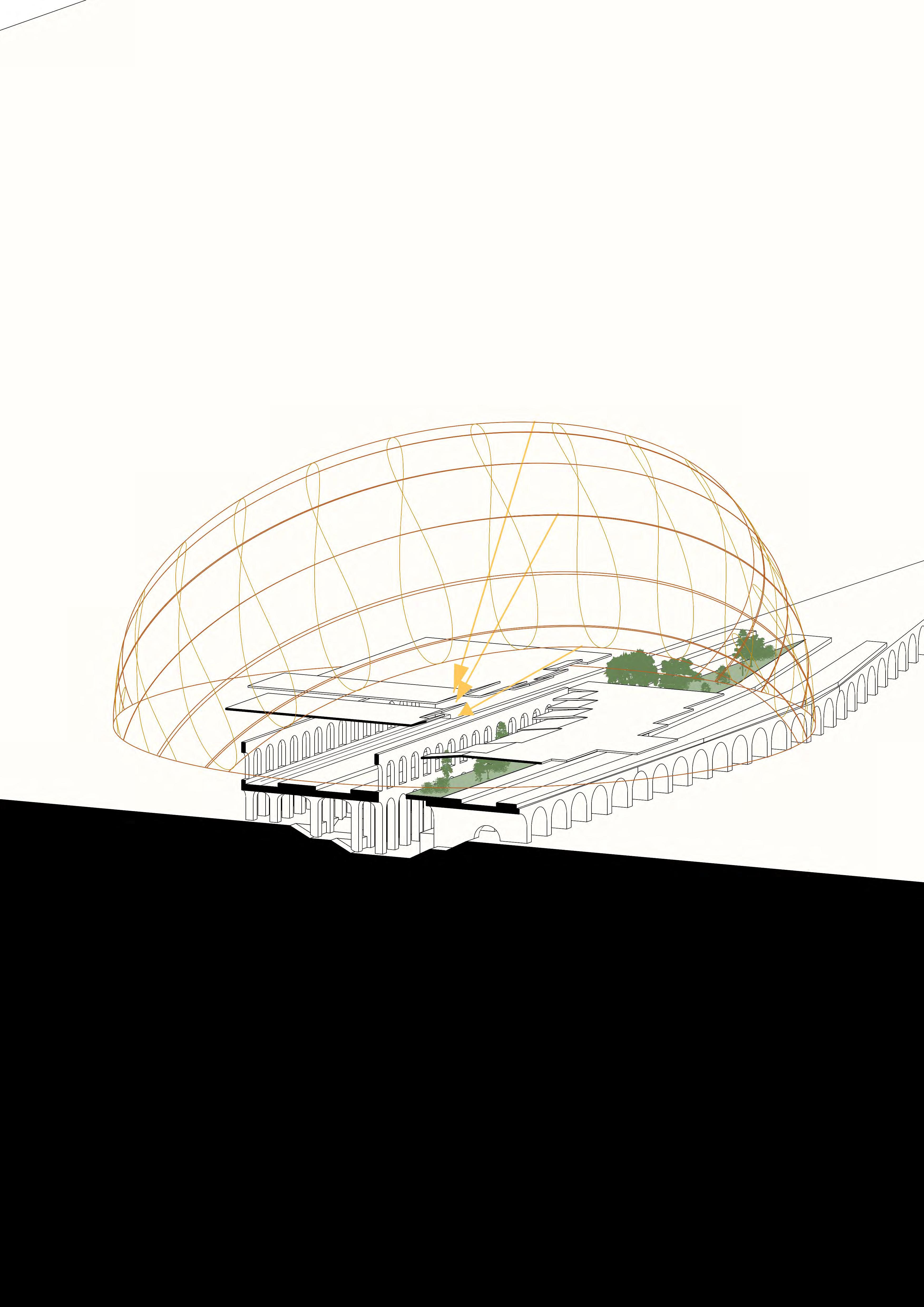
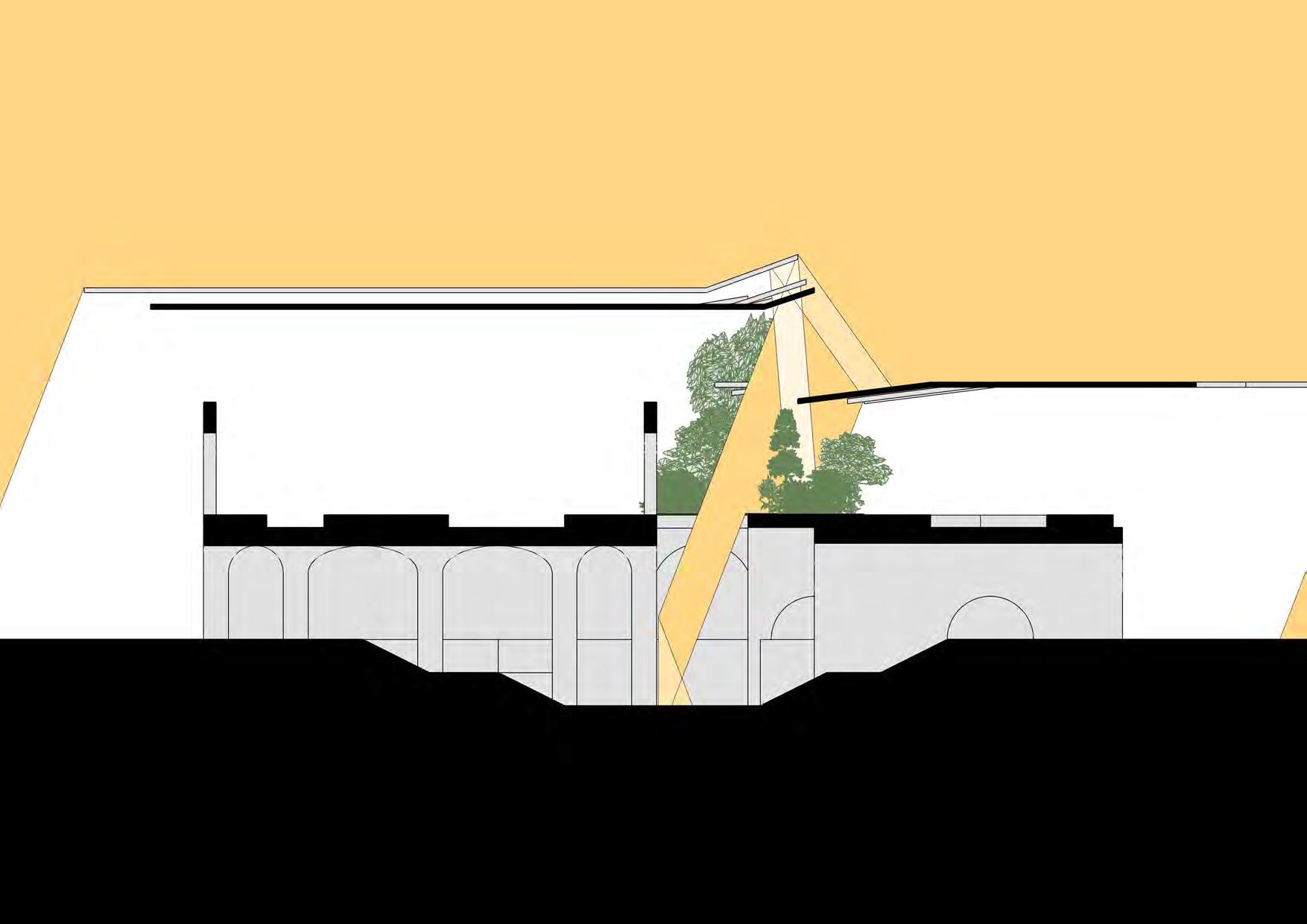
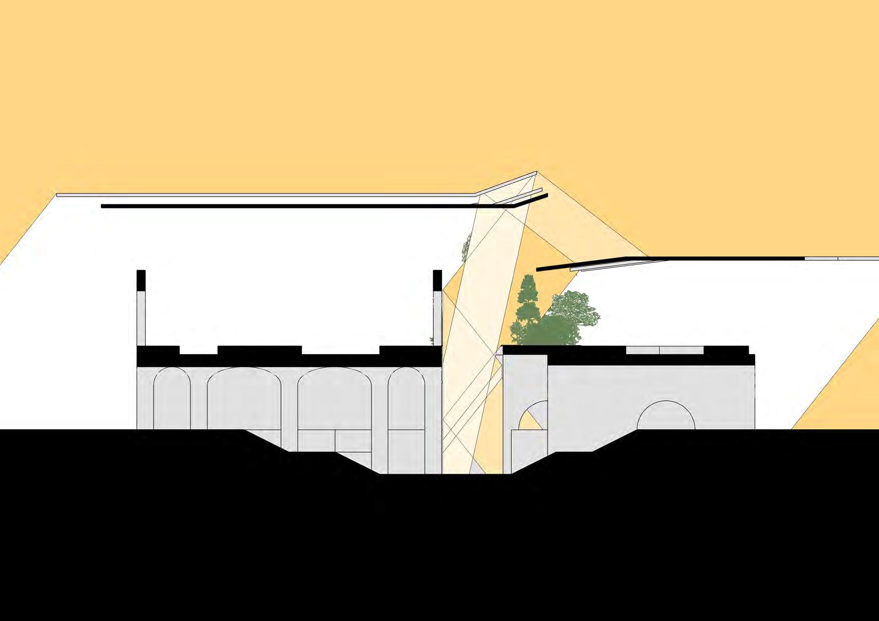
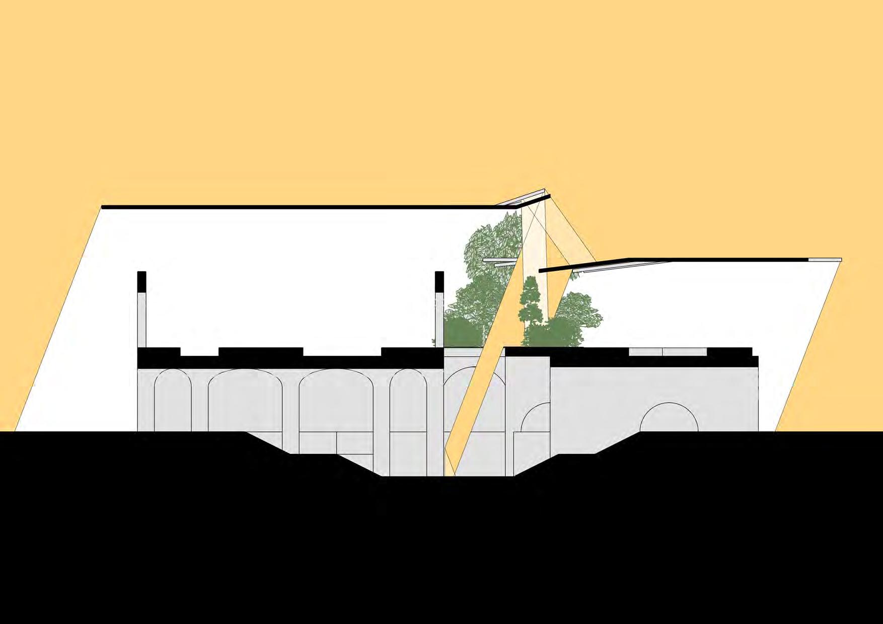
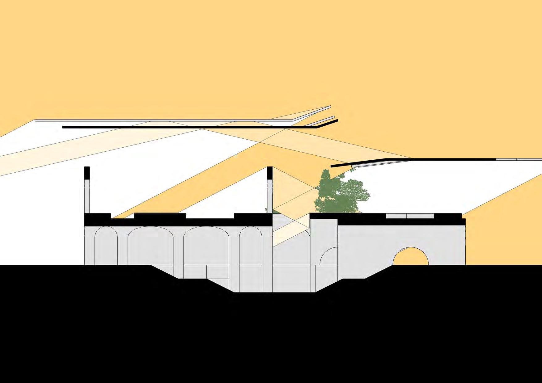
The atrium of the station is topped by a skylight in the roof. the tall narrow space aims to recreate the soft lit atmosphere found in Mediterranean streetscapes.
Raytracing the sun vectors across the roofs and façades informs on the required shape of the roof opening to reflect and diffuse light, while avoiding direct sunlight in the atrium.
Mediterranean Streetscape
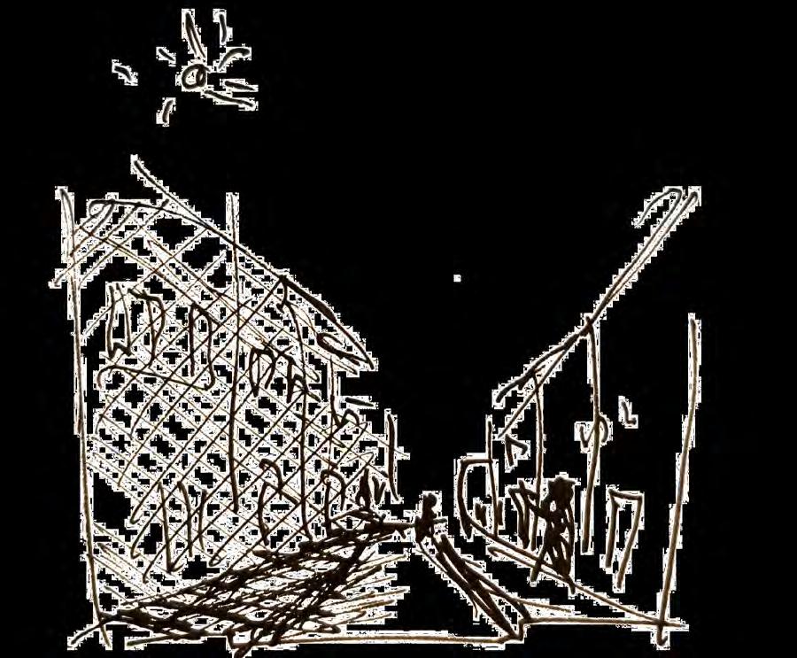
The height of the buildings draws enough shade to prevent direct sunlight from hitting the road, keeping pedestrians in a cool environment.
Sun angles at noon at solstices and equinoxes are considered to assess the performance of the roof and façades to diffuse the light.
Sunpath Diagram
Summer Solstice Spring/Autumn Equinoxe
Winter Solstice
Structure Tectonics
An in-depth exploration of the structural form and behaviour.
Concept - Design Approach
Nîmes ties its Roman heritage with the Provence culture and its Mediterranean climate. This can be observed as a set of values in the city fabric that should be reflected into the new station design. Furthermore, its preserved façade must be engaged with in a sensible manner.
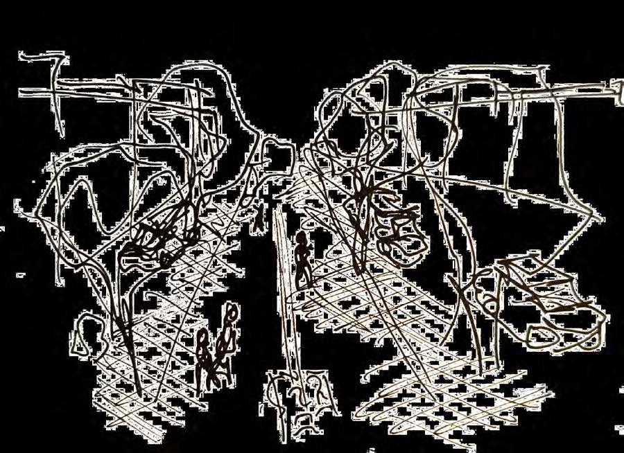
Wide pedestrian ways lined with trees with narrow car lanes on the sides.
The sun does not reach the ground harshly but bounces off the facades for more diffused light and a cooler climate.
Order and Harmony
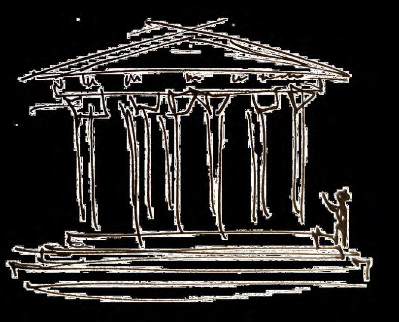
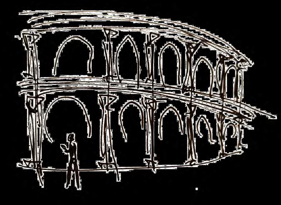
The Square House and the arenas of Nîmes have displayed the roman harmonious shapes and proportions that inspired the city’s architecture for millenia.
Boulevard
Narrow Street
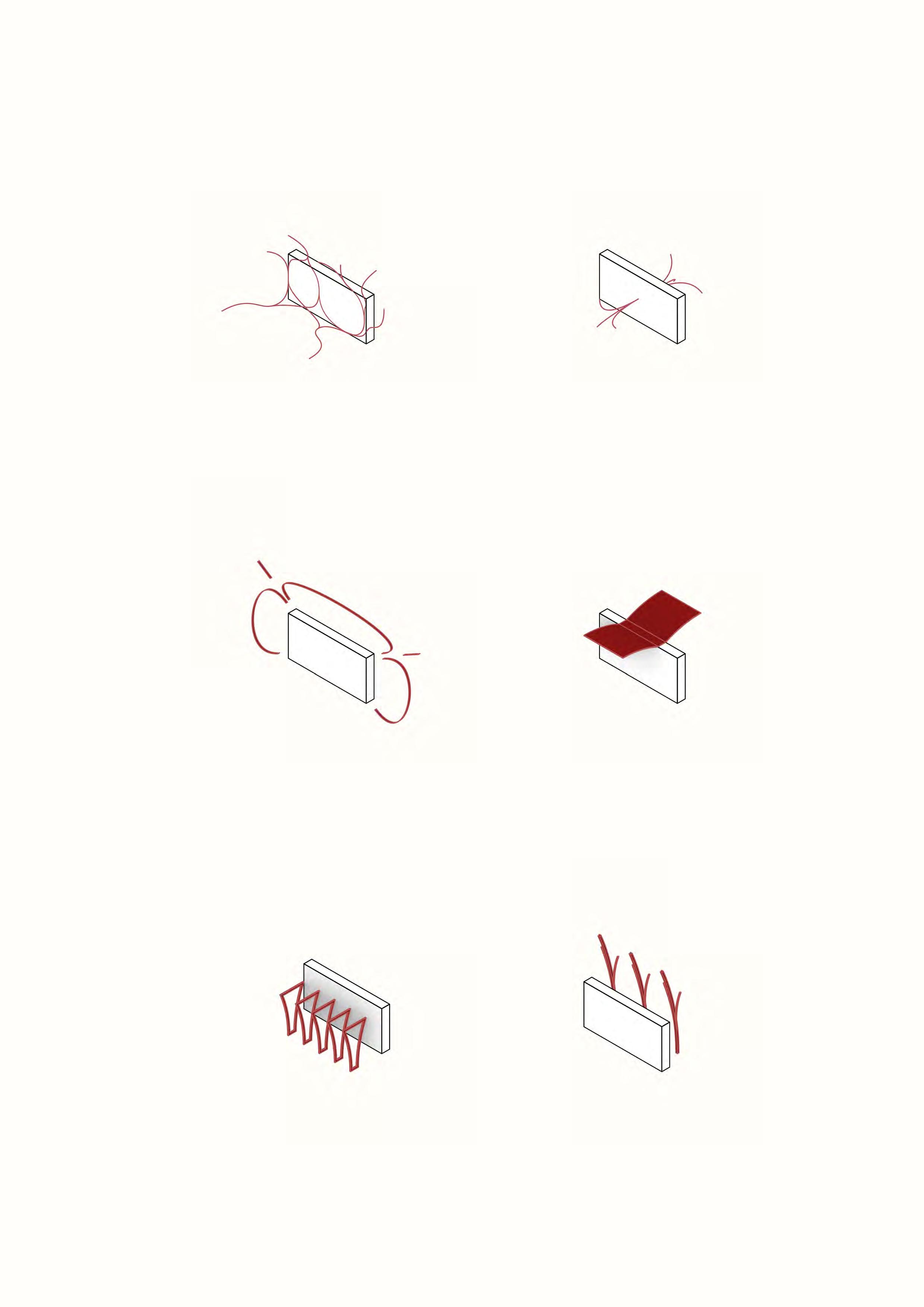
Façade Treatment Solutions
Various solutions are investigated for their positive and negative impacts on the façade.
Entangle
Too invasive to the façade, more appropriate for decayed structures.
Pierce
Appropriate as two interweaving elements, not too invasive on the façade.
Radiate
Requires bigger strucures, more appropriate for small precious elements.
Support
Conflicts between the language of the façade and the structure, gap is preferred.
Shift
Shifts from and appropriately echoes the façade language.
Overtake
Expands the façade language higher, defines the elements distinctively.
Concept - Structural Approach
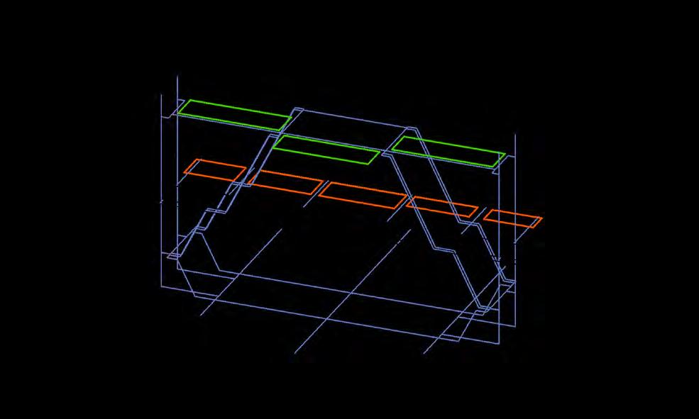
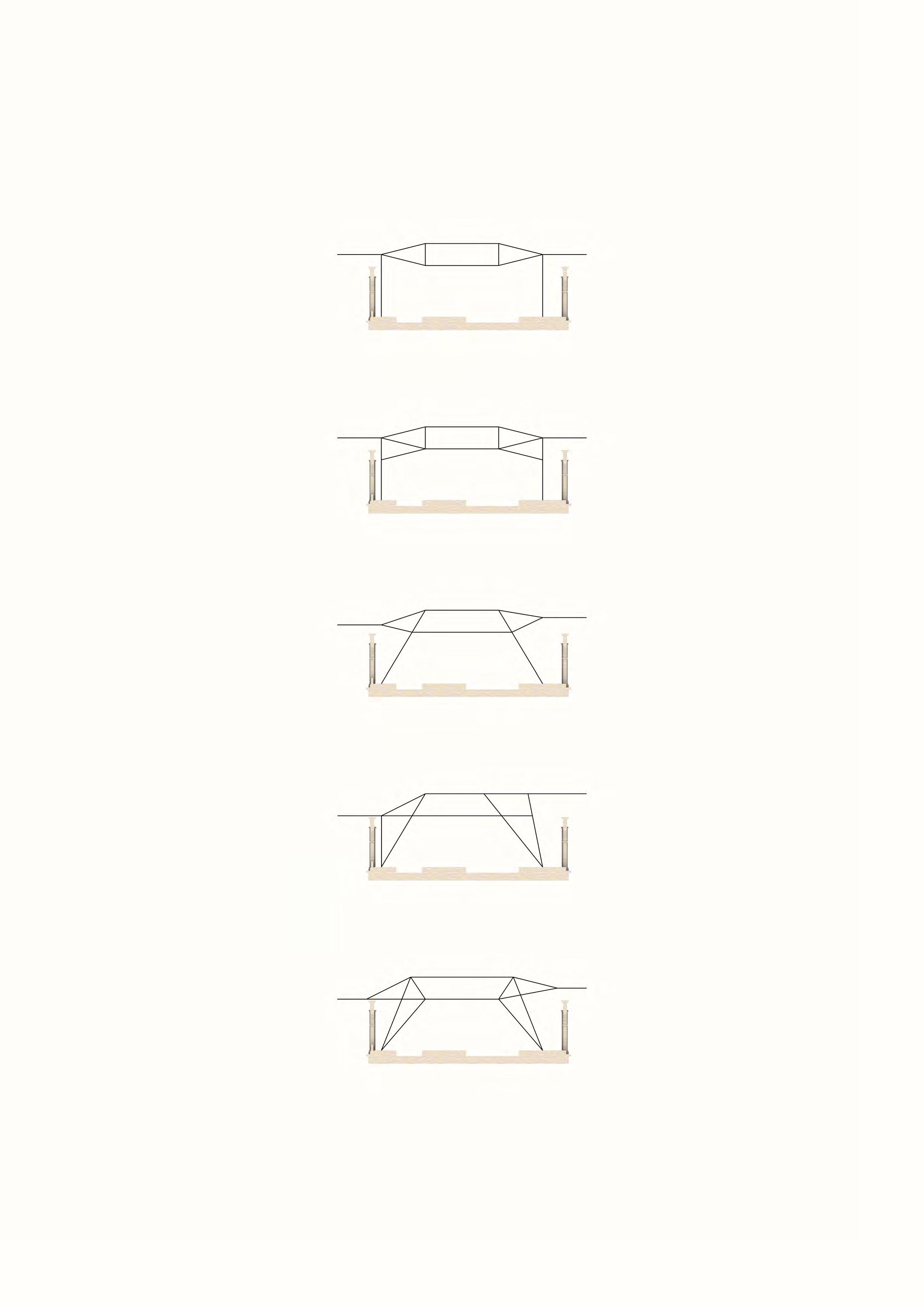
The insertion of a new structure above and within the existing stonemasonry build requires an assessment of a structure’s performance, stability and adaptation to the program. The exploration will focus on a fragment of the roof structure between the existing façades. The design aims to meet the following criteria.
Vertical & lateral stability
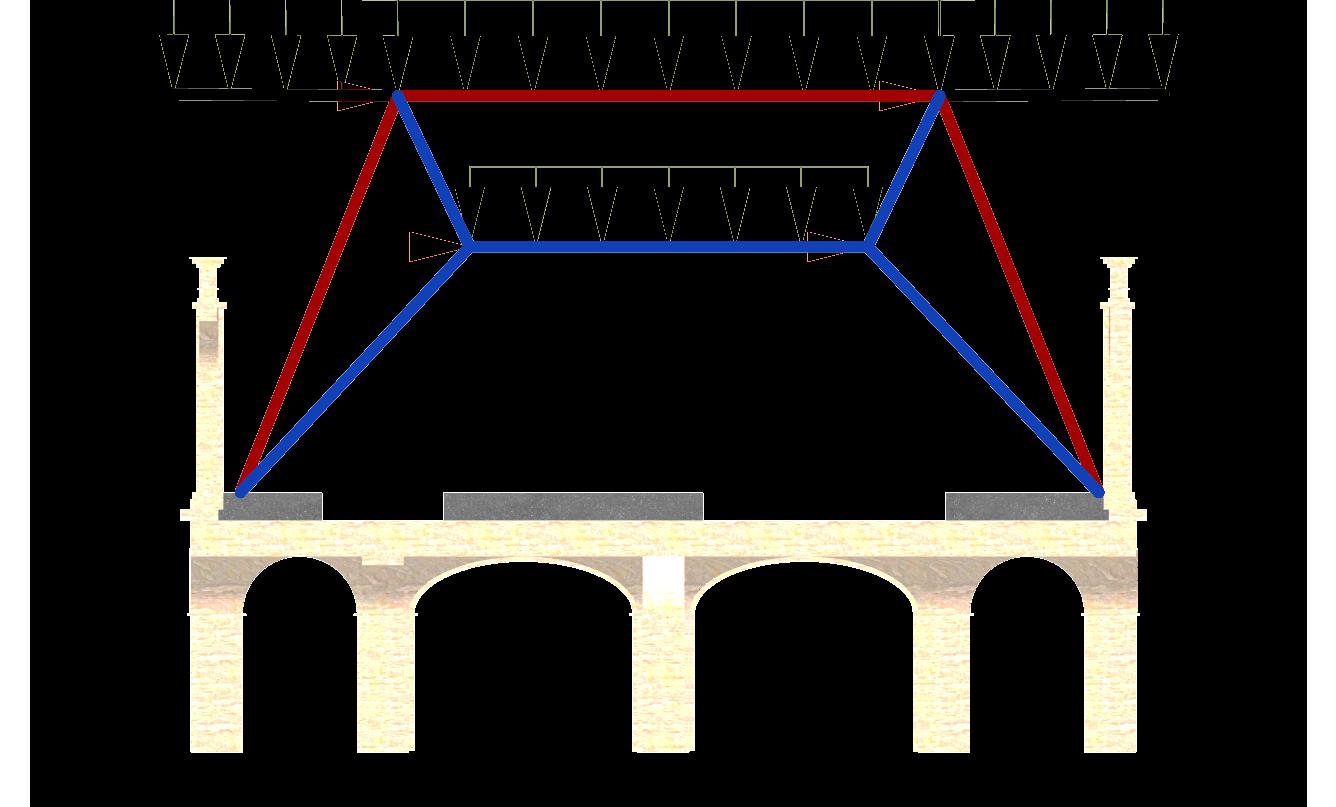
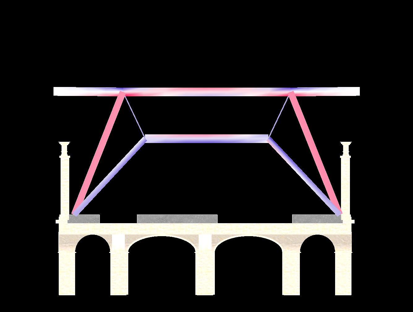
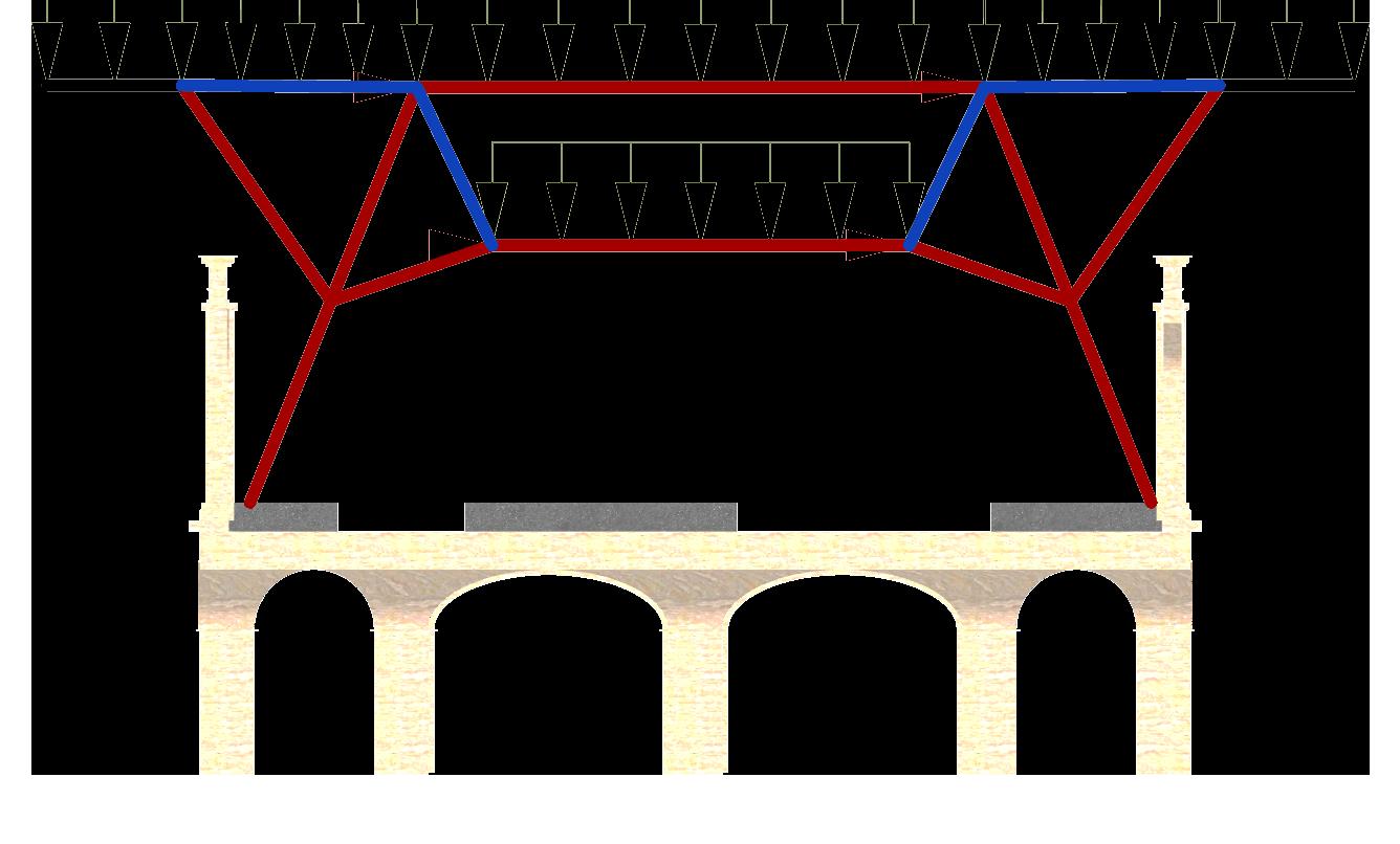
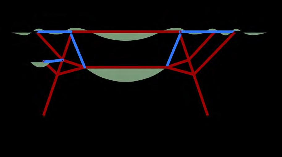
A wide-span structure requires lateral stability, due to its fue supports, using moment connections (green) and triangular trusses. The forces are analysed for vertical loading (compression in red, tension in blue).
Levels modulation
The structure must arrange the roof, mezzanine and circulation levels, to maximise accessibility and internal and external views.
Vault geometry
The station aims to create unity in its spaces. The structure must follow an arched composition to focus the platforms into a singular space.
Construction diagrams
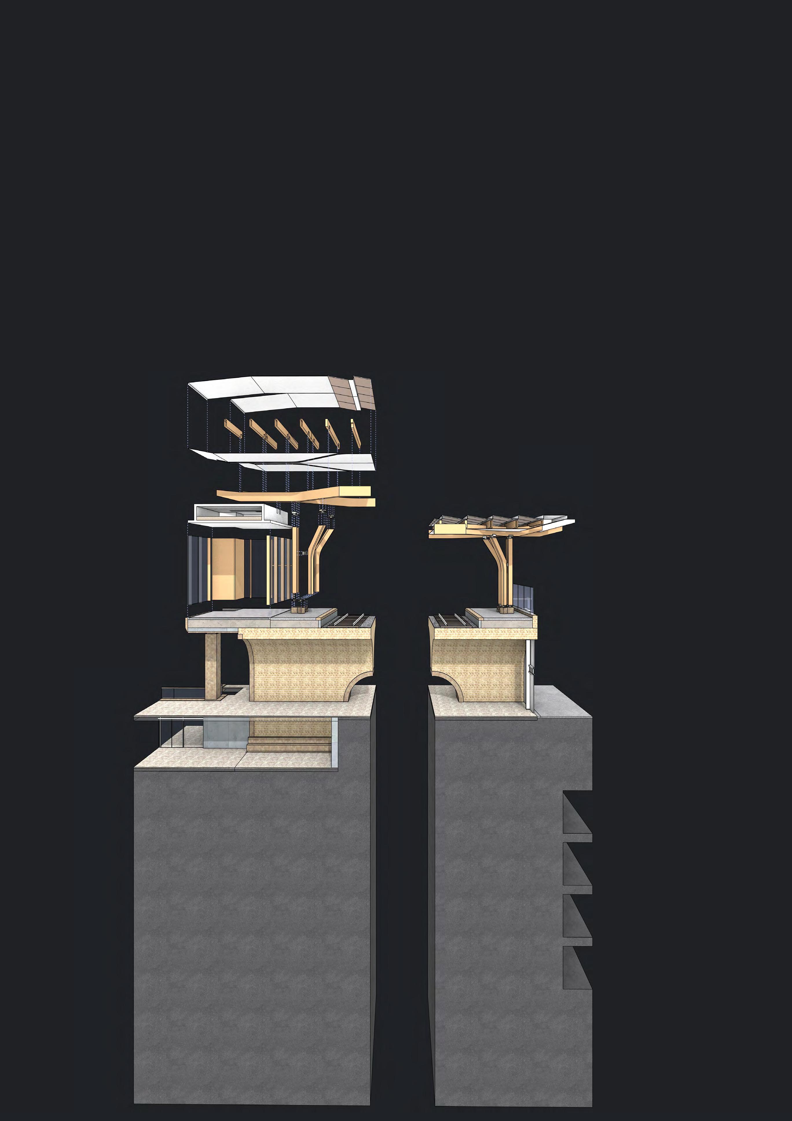
The truss consists of timber elements sized based on the loading conditions. Beams and columns become continuous members that intersect to follow the mechanics of the studied trusses. The spaces and circulation platforms naturally take shape around the construction .
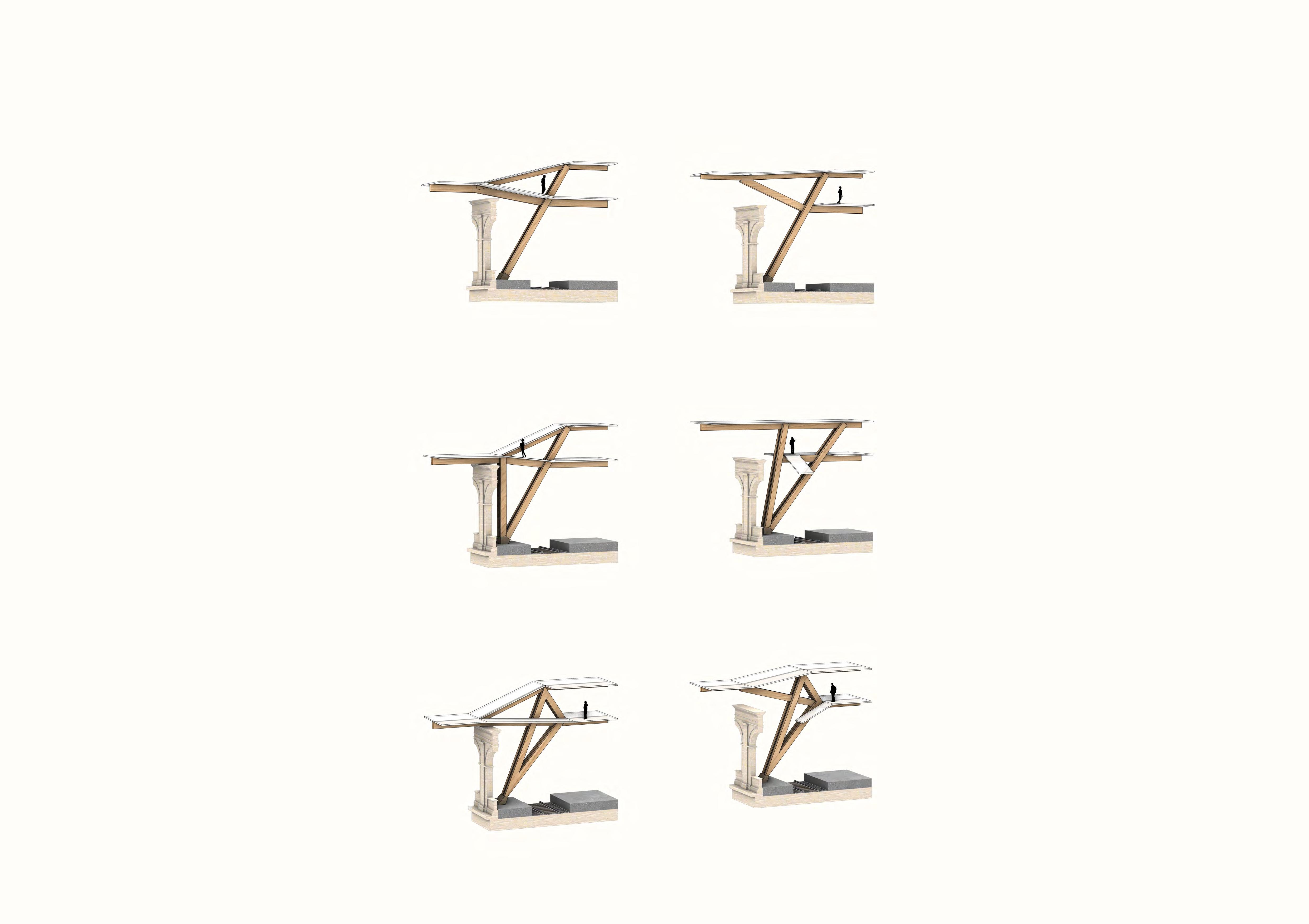
Structure - early Fragments
The truss forms are developed further into iterations of structural language. The mezzanine is embedded in the structure, where the truss forms wrap around thw space.
Iteration 1
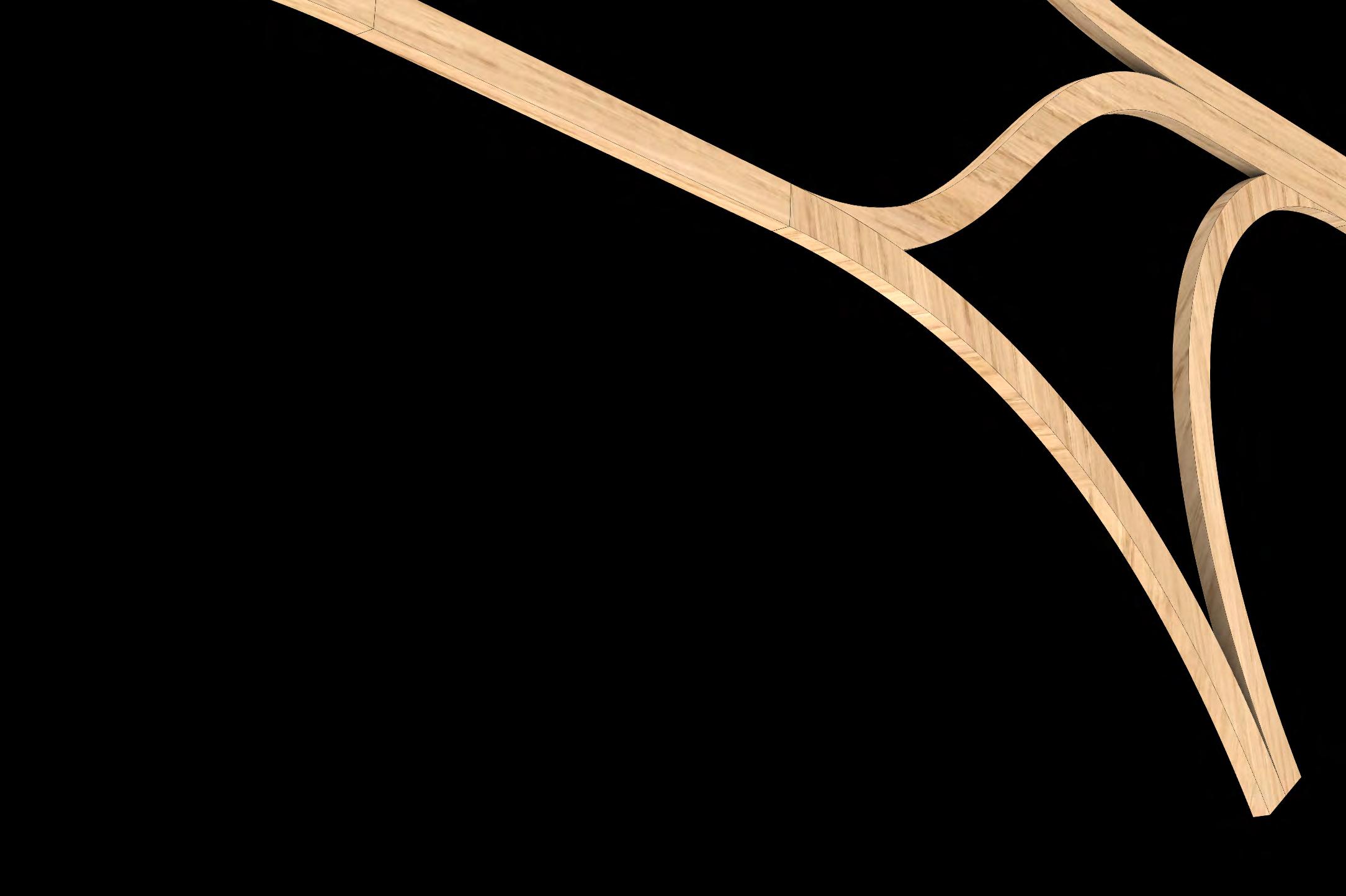
Glulam elements are bent into arch forms that emphasise a vault typology. Columns merge with beams to create a continuous seamless language. However the joinery methods are not sufficient for structural stability.
Iteration 2
The continuous language is exclusively applied to the beams, while the columns act as stilts that cross through the beams. However, the form does not act as avault or a truss.
Iteration 3
The columns are developed as frames, on which the beams attach. The column frames resist the moments and can widen to channel circulation.
Iteration 4
Structs fan out of the columns to reinforce the beam connections and creat new sub-spaces within the structure. This allows the columns to be more continuous with the beams and bring back the vault typology.
Structural behaviour
Contained lateral loads
The North frame introduces challenges of structural stability regarding the existing structure. This strategy aims to minimise the impact on the structure by only transfering lateral loads that are applied externally, such as wind.
Structure Type
The structure behaves like a simplified cambered truss. The upper members take are under compression while the lower members tie the system together, containing the lateral loads.
Loading Condition
The roof an mezzanine are under significant vertical loading from dead and live loads. Wind loads remain minimal, transferring minimal lateral loads onto the stonemasonry structure.
Compression
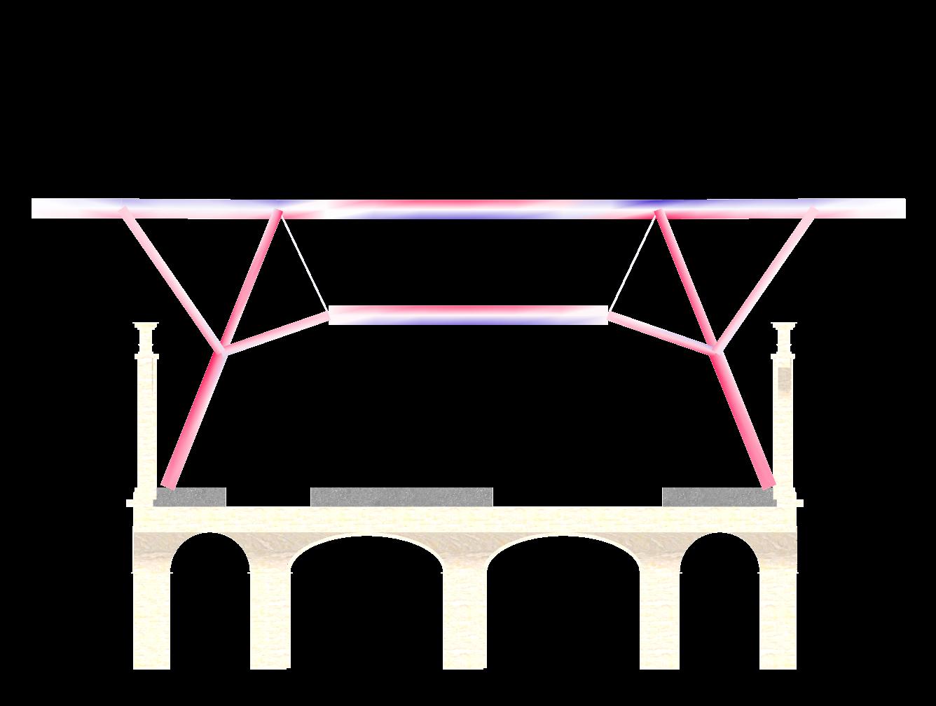
Stress Analysis
The model behaves as predicted with the beams also in bending from the hogging and sagging mechanisms. The elements are sized to resist the loading ondition. The wind loads create a mild disruption in the tension members (on the right) but they remain overall in tension
Structural System - Iteration 1
Curved glulam columns sprout off the platform to reach the beams of the terrace, mezzanine and roof. The columns are assembled in triangle frames for more lateral stability.
Fragment
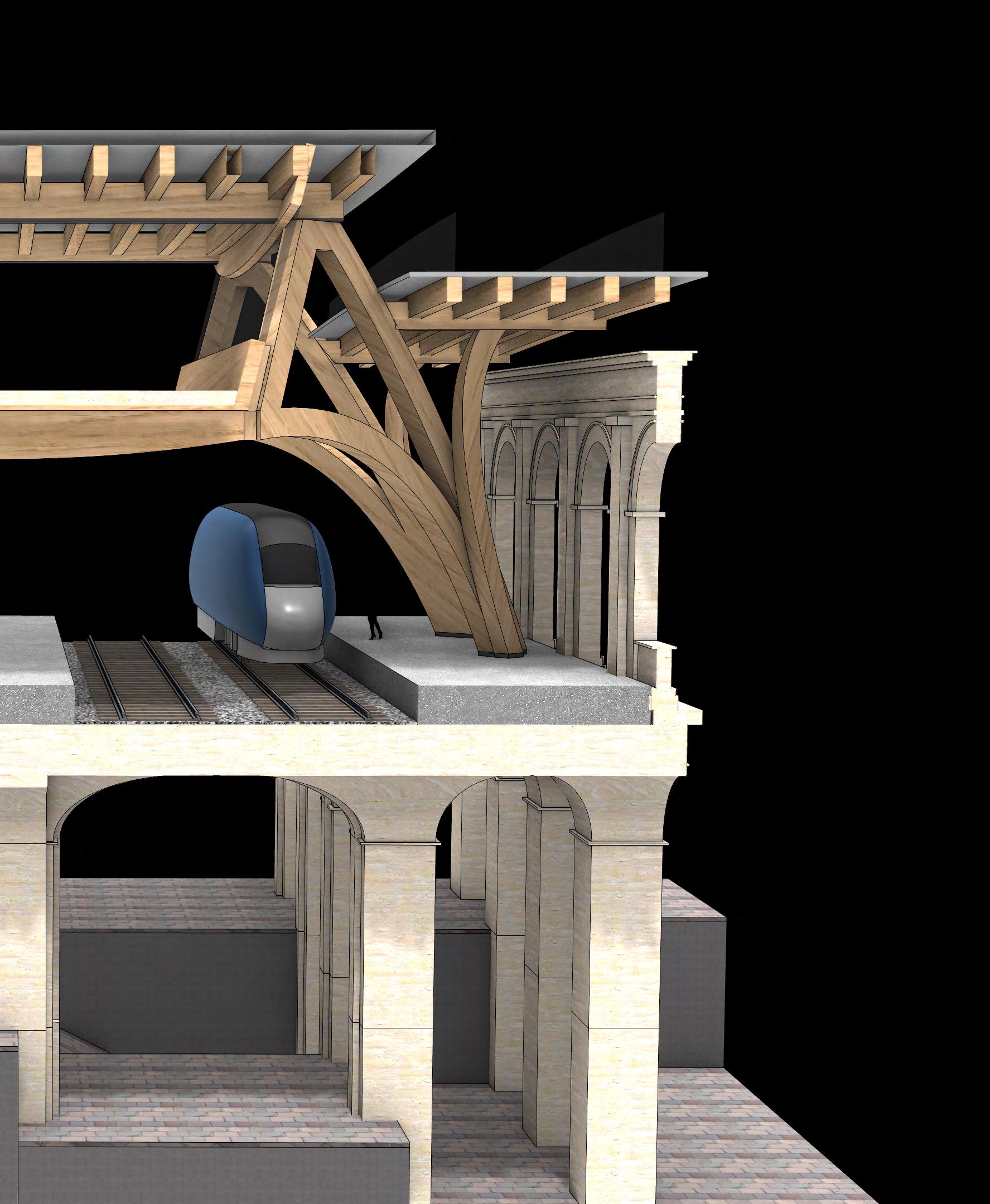
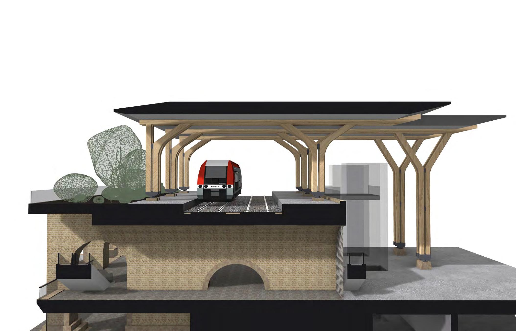
The structure curves around the existing façade wall and follows its delimitation, to overtake without dominating it.
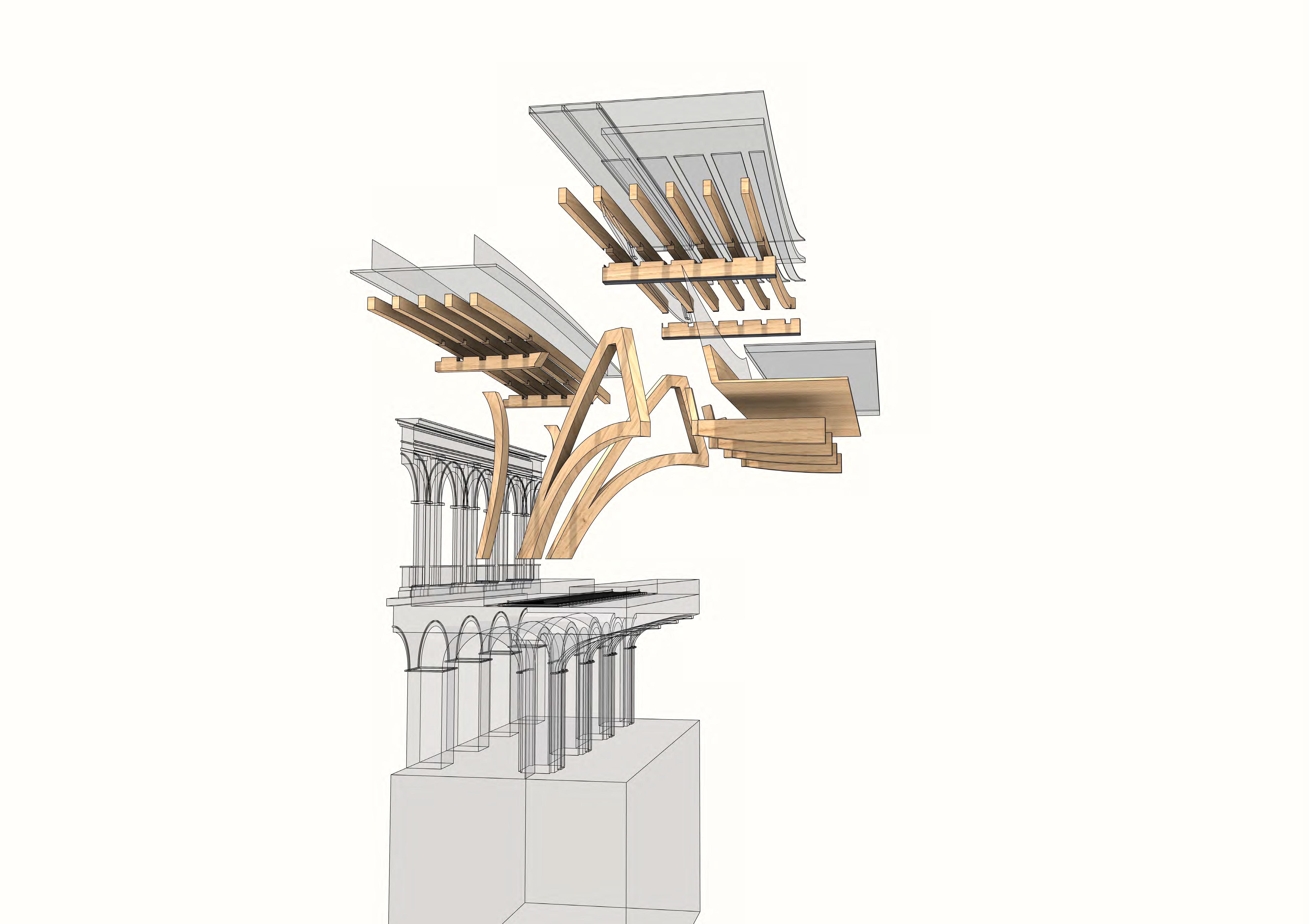
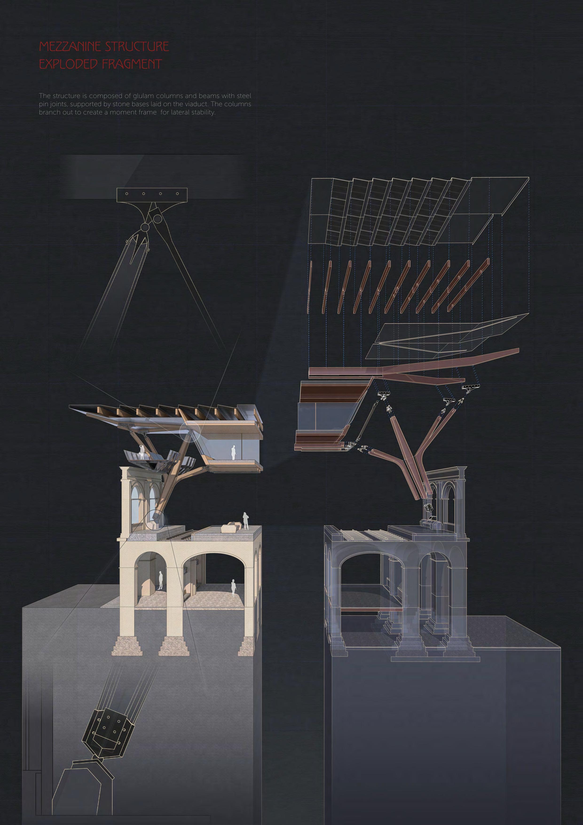
Exploded Fragment
The primary beams and columns span across the platform to embody the vaultypology. Whereas the secondary beams evoke the continuity along the train tracks.
Mezzanine Structure
Each level is shifted halfway up, to allow open views onto the platforms and the city from the mezzanines.
Structural behaviour
Transfered lateral loads
The North frame is this time analysed for a simpler system, where lateral loads are transfered to thestone viaduct.
Structure Type
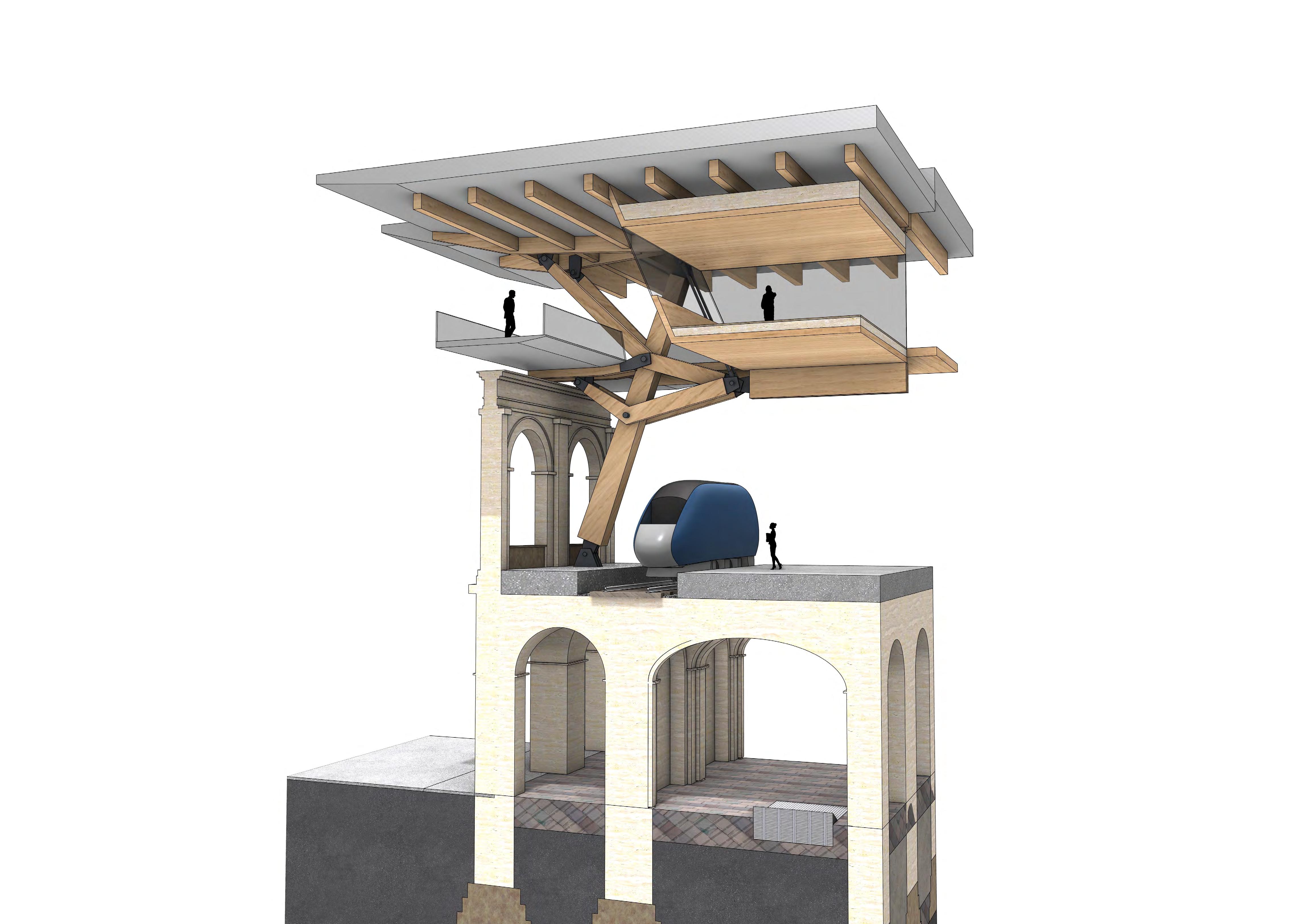
The structure consists of primary columns branching out to support the roof and mezzanine. This system is a braced frame, which is more open and allows for bigger overhangs.
Loading Condition
The loading remains the same with significant vertical loading on the roof an mezzanine and minimal wind loads. However, the structure has leaning columns transfering an induced lateral load at each support.
Compression Tension
Stress Analysis
The model behaves as predicted with the beams also in bending from the hogging and sagging mechanisms. The elements are sized to resist the loading ondition. The tendons are under little tension but their role is crucial for stability. Witout them, th model fails.
Existing Structure Reinforcement
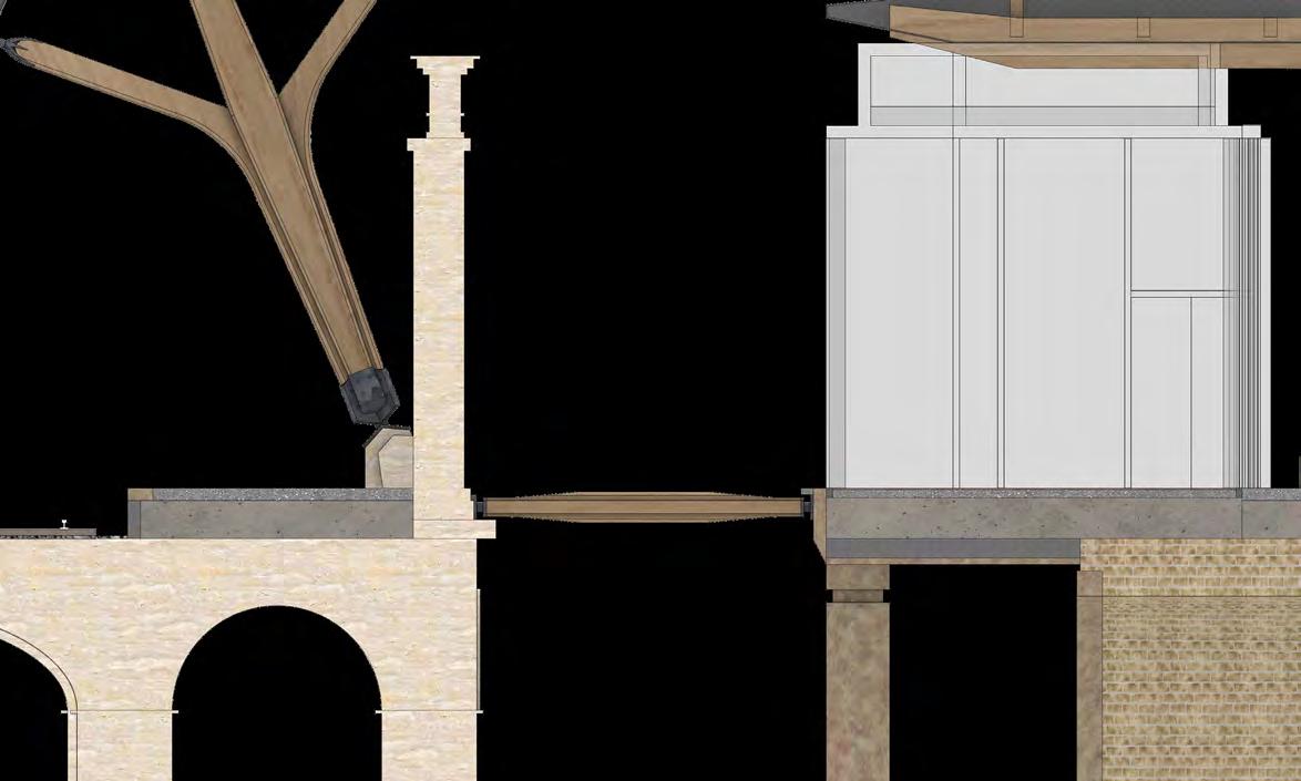
The loads from the structure are deconstructed into the vertical component through the stone pillars and the lateral component through a strut crossing the atrium to the south part of the viaduct which, as a barrel vault, resists shear.
Structural System - Iteration 2
The structure reconciles several challenges to support the roof, between train tracks and existing façades, it must also carry mezzanines and platforms. This acrobatic situation recalls the posture of Atlas crouched under the weight of the sky.
Roof Condition
Defining Curves
Load Path Diagram
Compression Tension Bending Moment
Atlas Analogy
Rationalised Linework
Structural elements
Fragment of the Structure
The members are assembled with steel pin joints that highlight the mechanisms of the structure.
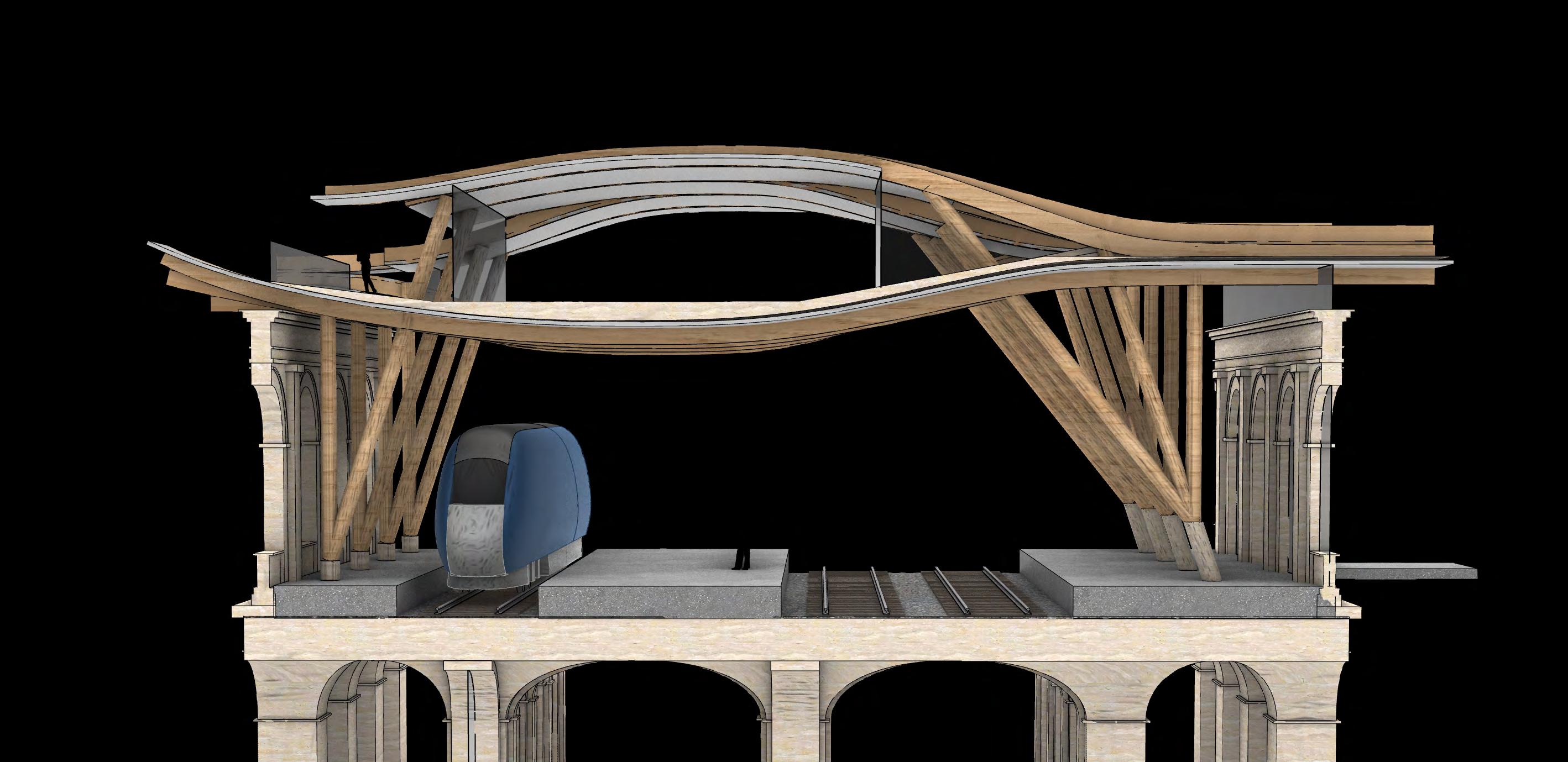
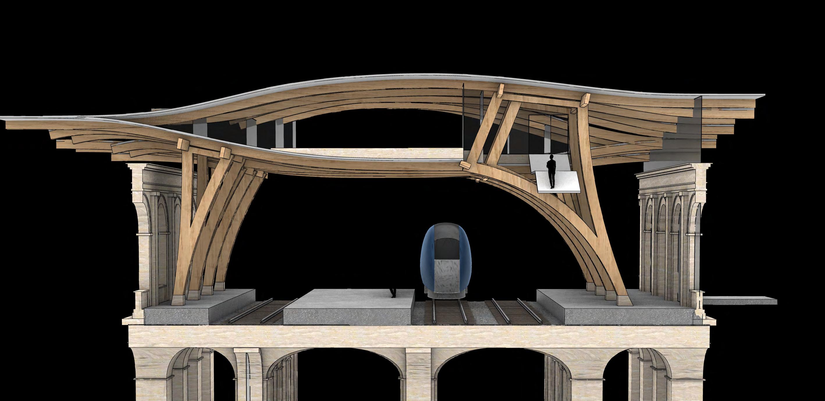
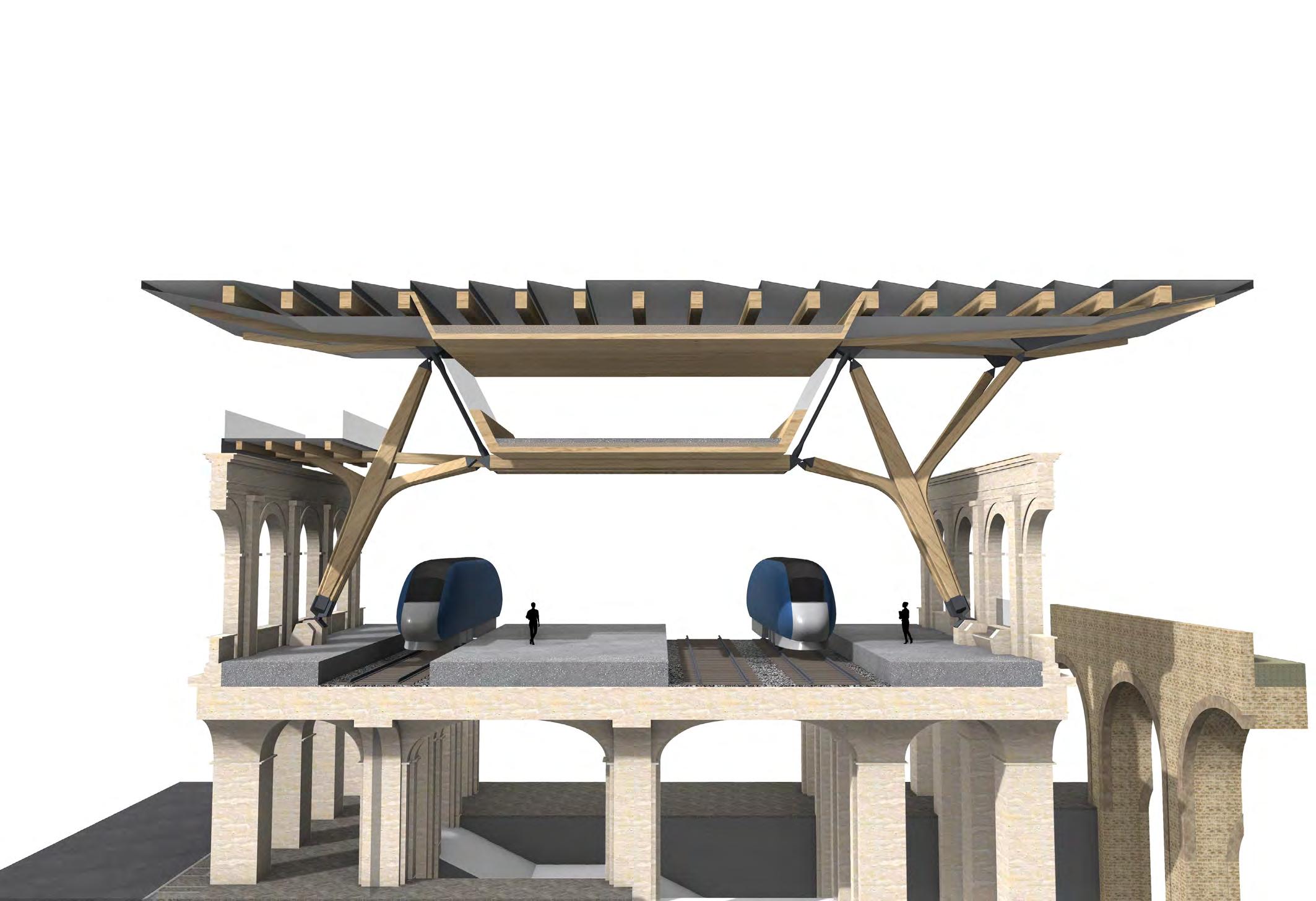
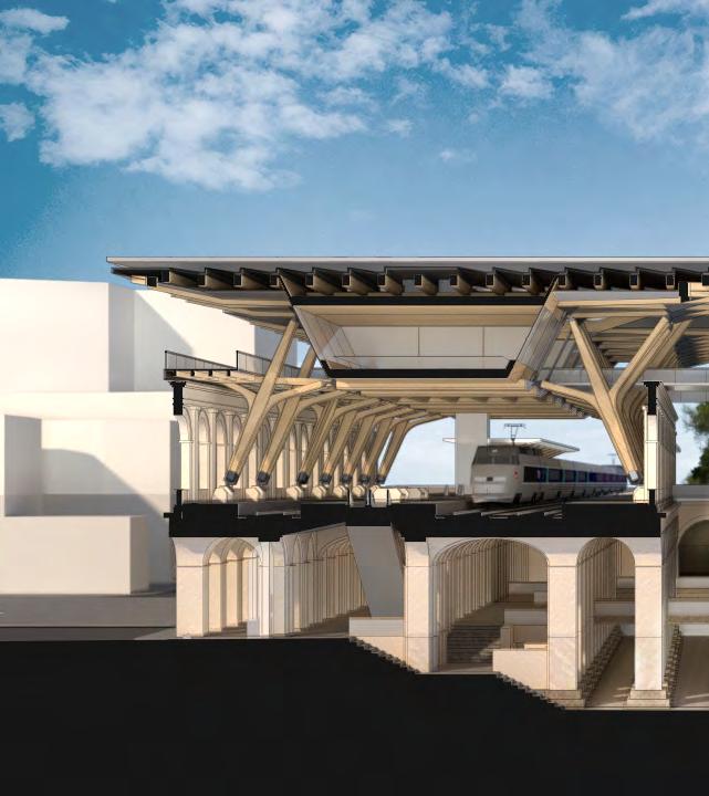
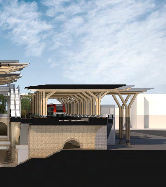
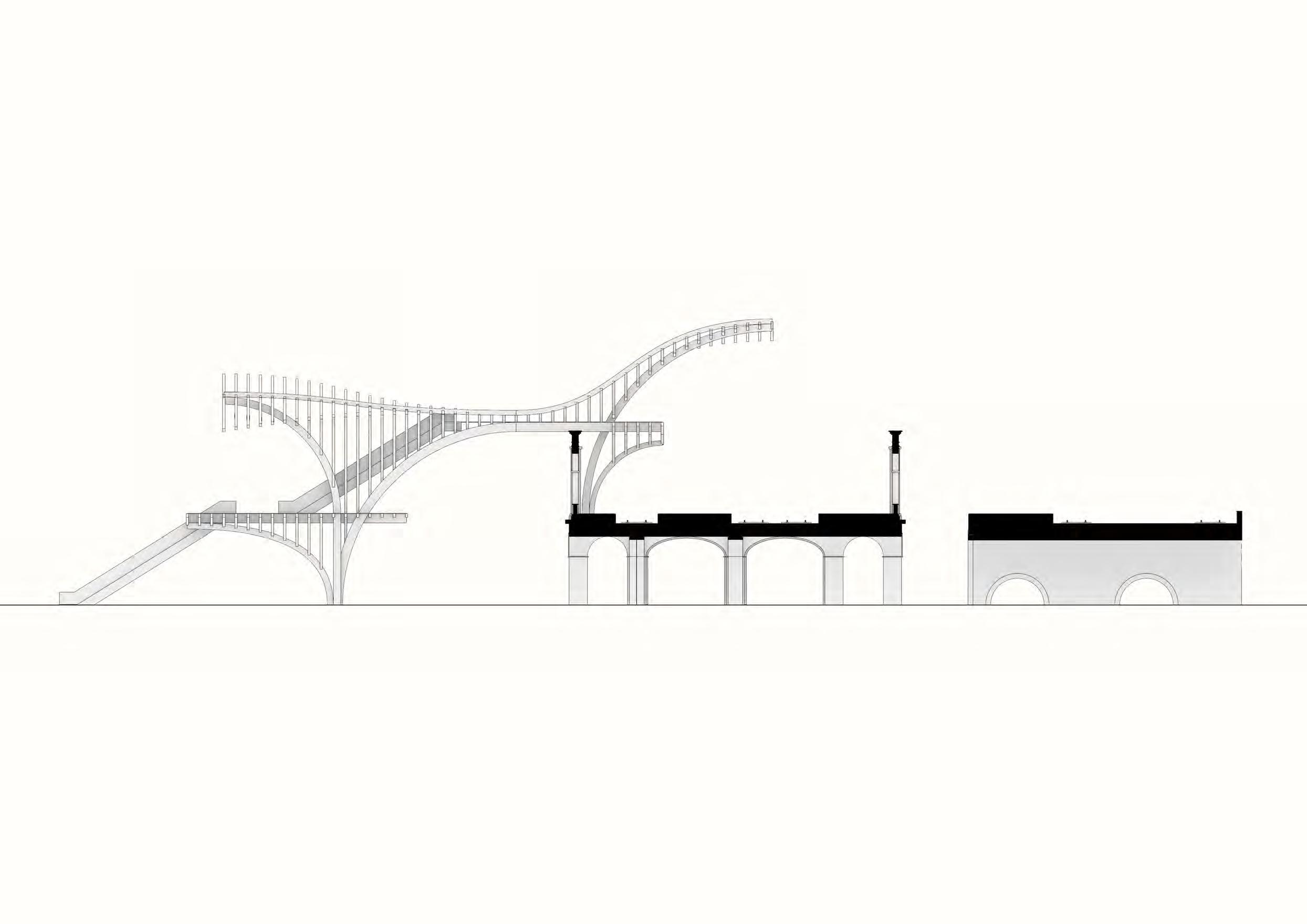
Overall Section
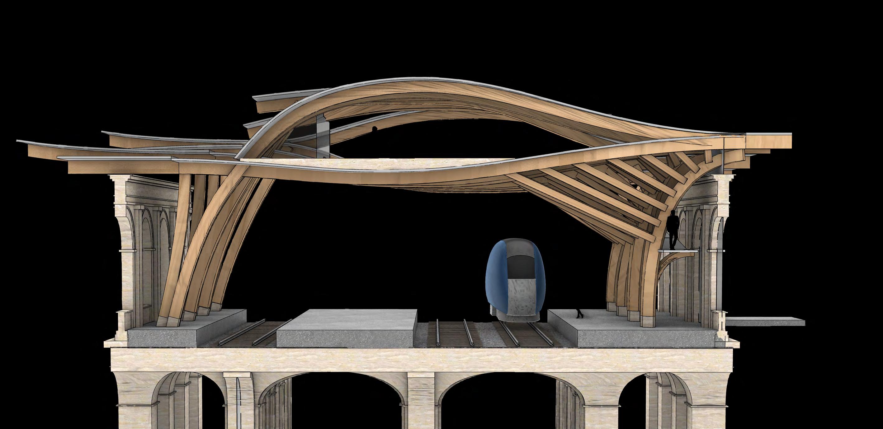
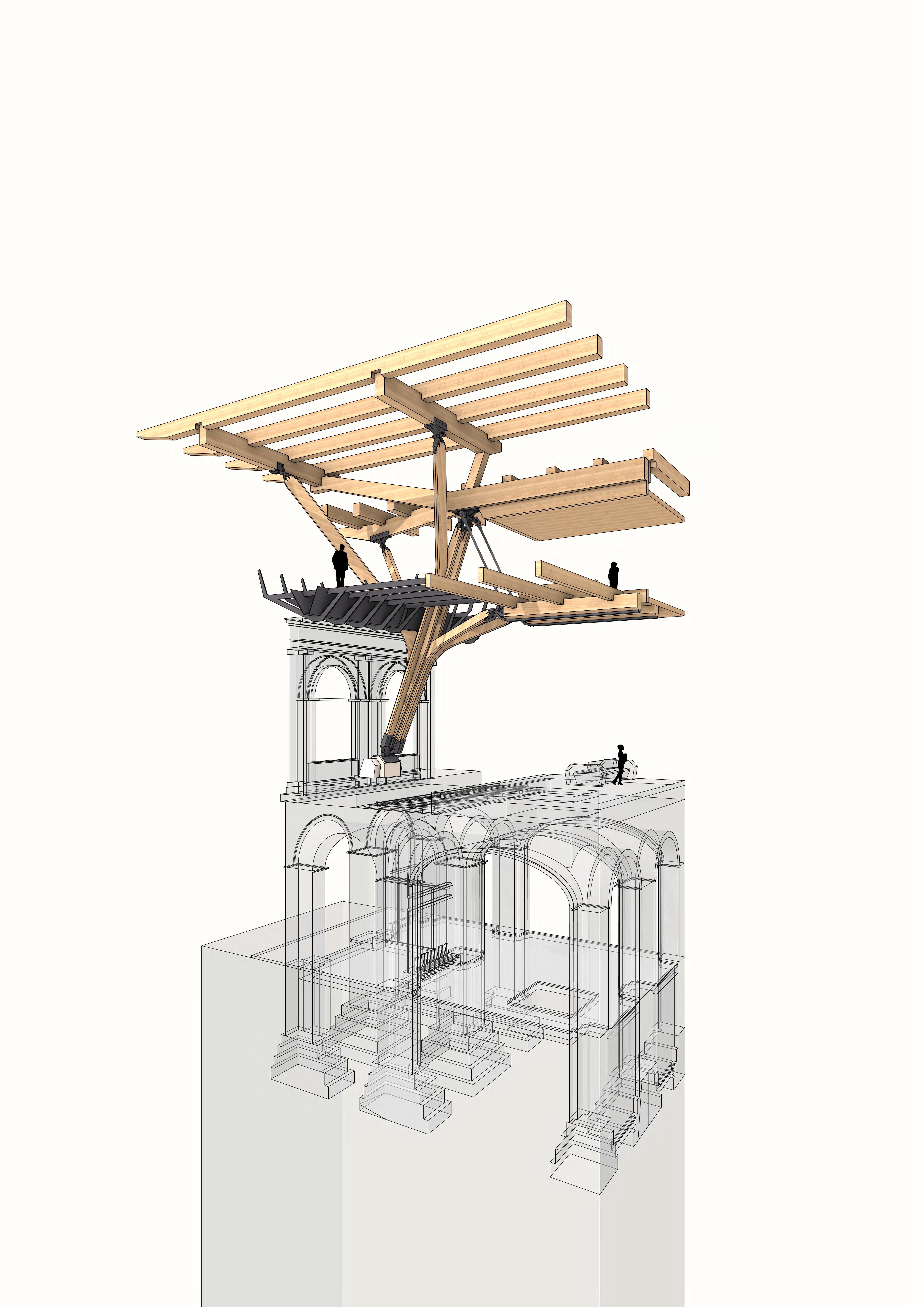
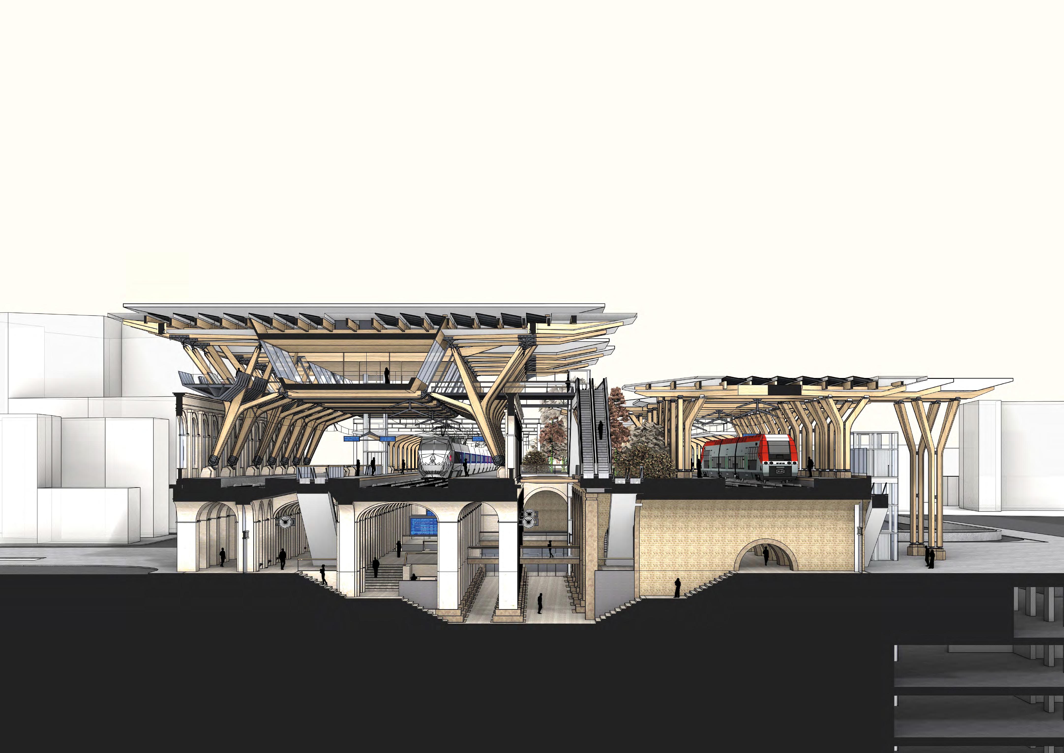
The structure for the mezzanine restaurants is more dynamic, expressing the structural constraints. The structure on the South side has a simpler form, as it only works as a canopy roof.
KoldingHUS, Kolding
Inger & Johannes Exner
Koldinghus is a retrofitted castle with new internal columns that hold the whole new roof. It consist of wide connections at the base and tapered connections at the top, emphasising the language of the radiant branches.
Column Elevation
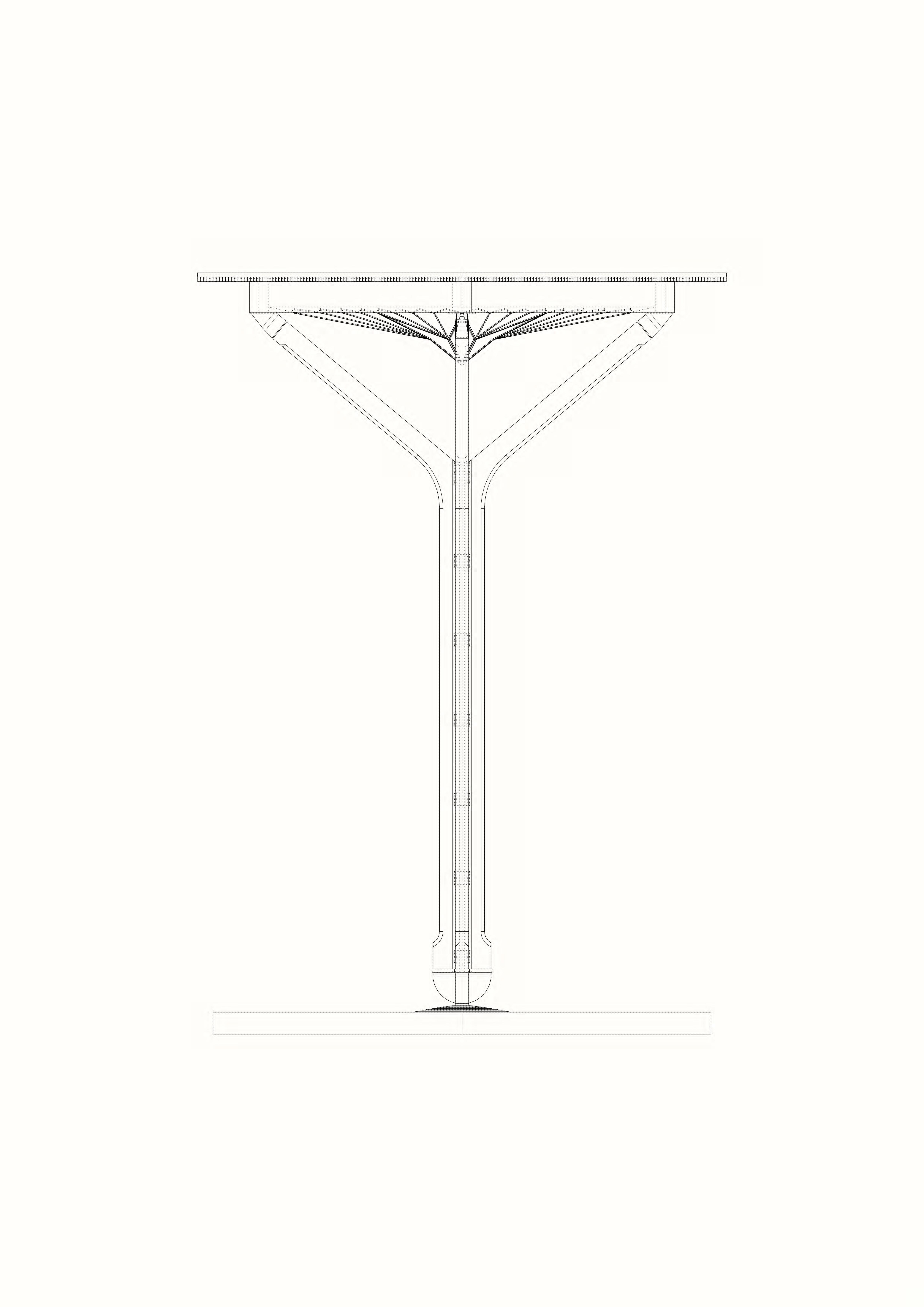
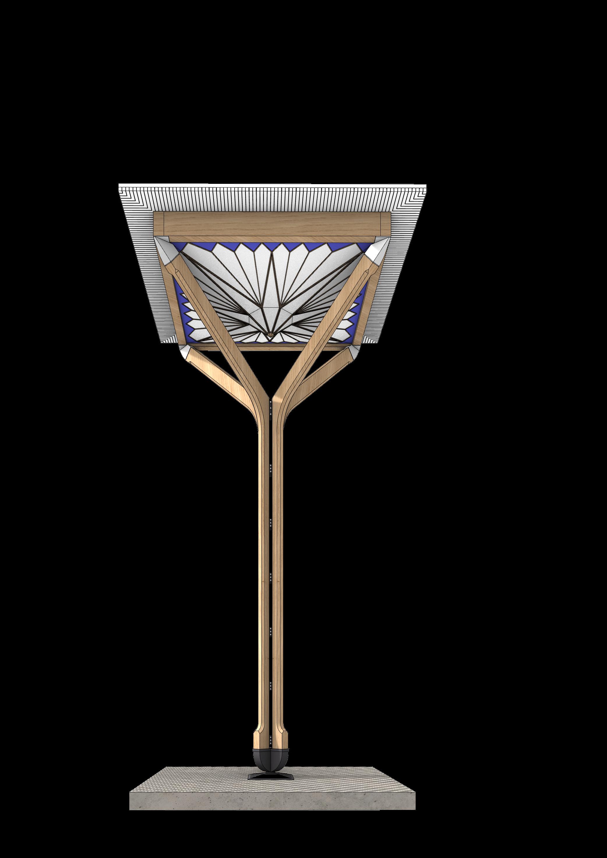
The column form is biomorphic, with a trunk consisting of bundled members that radiate out into a moment frame system in the roof.
Top Connection
The tapered form of the steel connection conveys a general taper in the member. It also matches the 45° angle of the connection against the frame.
Base Connection
The column sits on a narrow point at the tip of a tapered base, the steel casing of the timber members is heavy and massive, conveying the weight of the structure concentrated at this point.
Structural System - Iteration 3
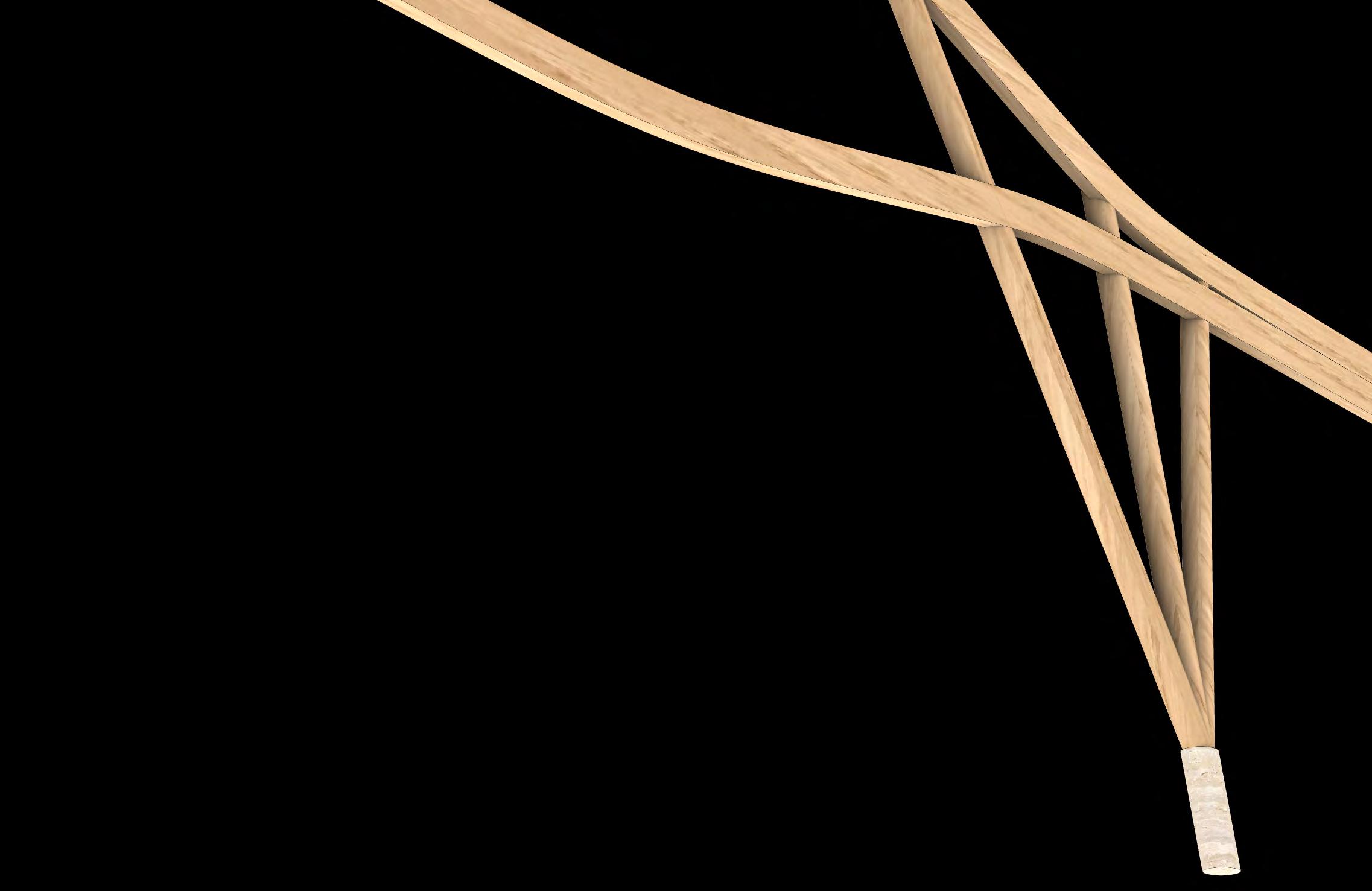
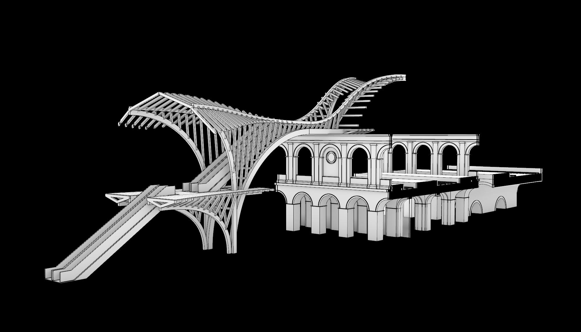
Following the structural language of Koldinghus, the members are simplified into a more rational system. Tapers and fillets enhance the structural behaviour. The connections express the load imposed on the structure but also lighten with a radiant form.
Fragment
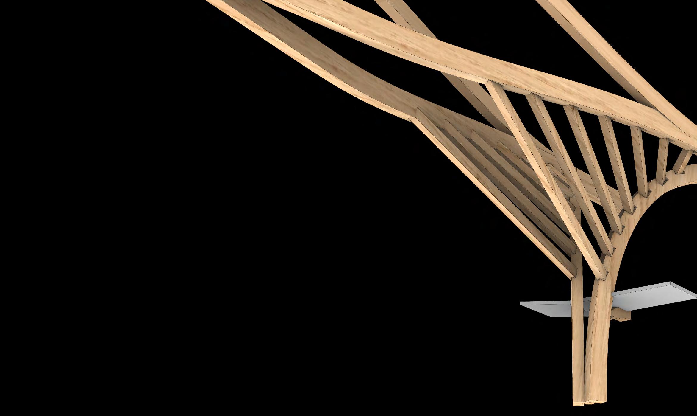
The column form consists of bundled members branching up like the biomorphic analogy from Koldinghus. The beam supporting the mezzanine is extended to the terrace and diagonal members transfer the loads to the column.
Mezzanine Structure
The structure is lighter, opening up the space towards the outside. The narrow contact points between the columns and beams and the ground and roof emphasise the distinction between the structural actors.
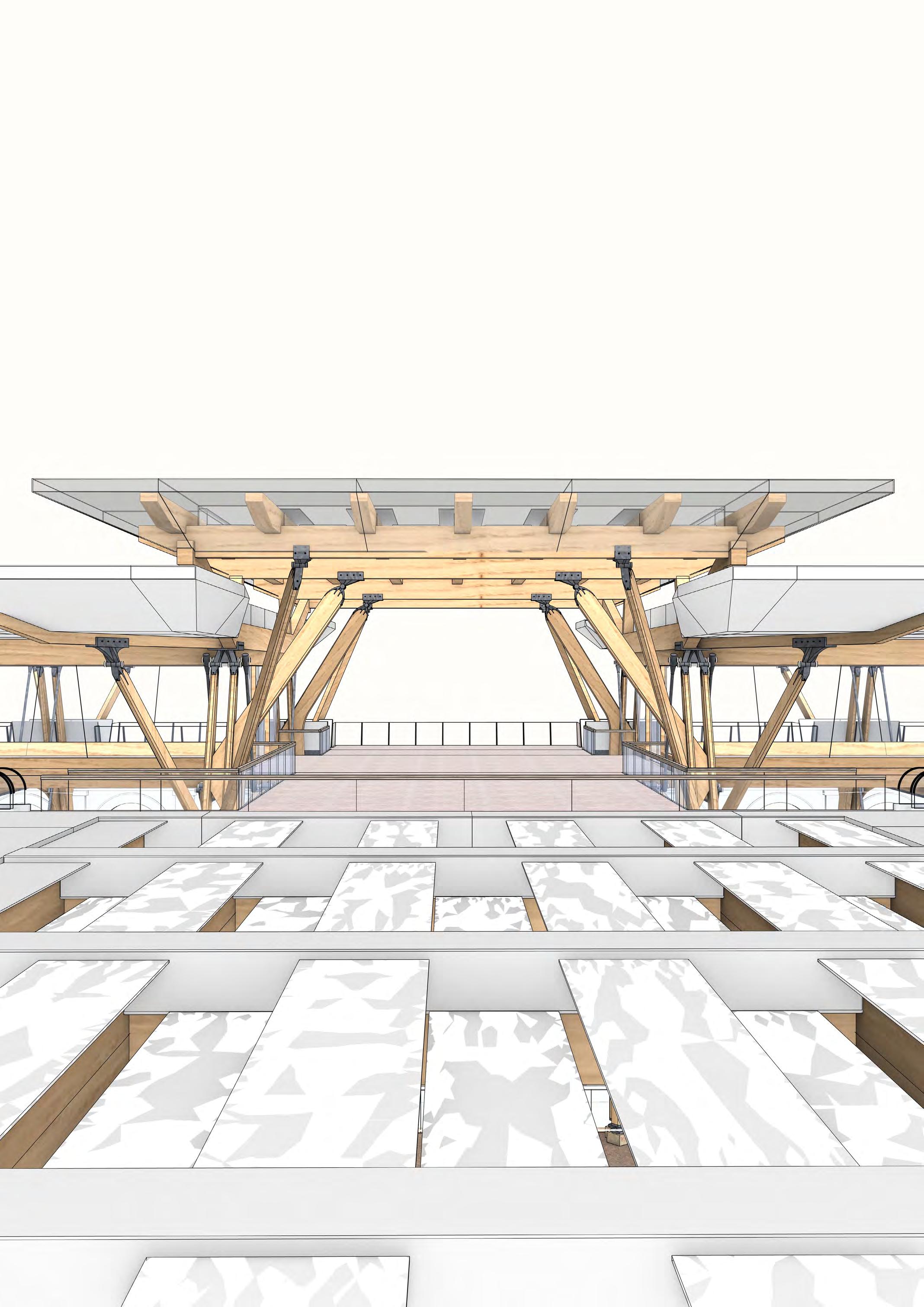
Canopy Structure
Columns come in pairs to frame the space with diagonal elements, while shortening the spans of the primary roof beams. Although it is simplified, the structure also behaves like a moment frame.
IBM Traveling Pavilion
Renzo Piano
The pavilion consists of timber members with steel connections. They are seamlessly embedded in the timber with finger joints. The steel connection does not only strengthen the general structure but is also versatile enough to integrate connection systems with the envelope.
Joinery Detail
The steel connectors consists of layered tongues that fit seamlessly into the timber members. This joinery guarantees tight fits resisting all rotations with minimal fastening.
The assembly is a vault with arches of the timber members supporting polycarbonate
envelope.
Barrel Vault
pyramids for the building
defines the vault form. The main members take in the vertical loads in the arch.
Structural System - Final Iteration
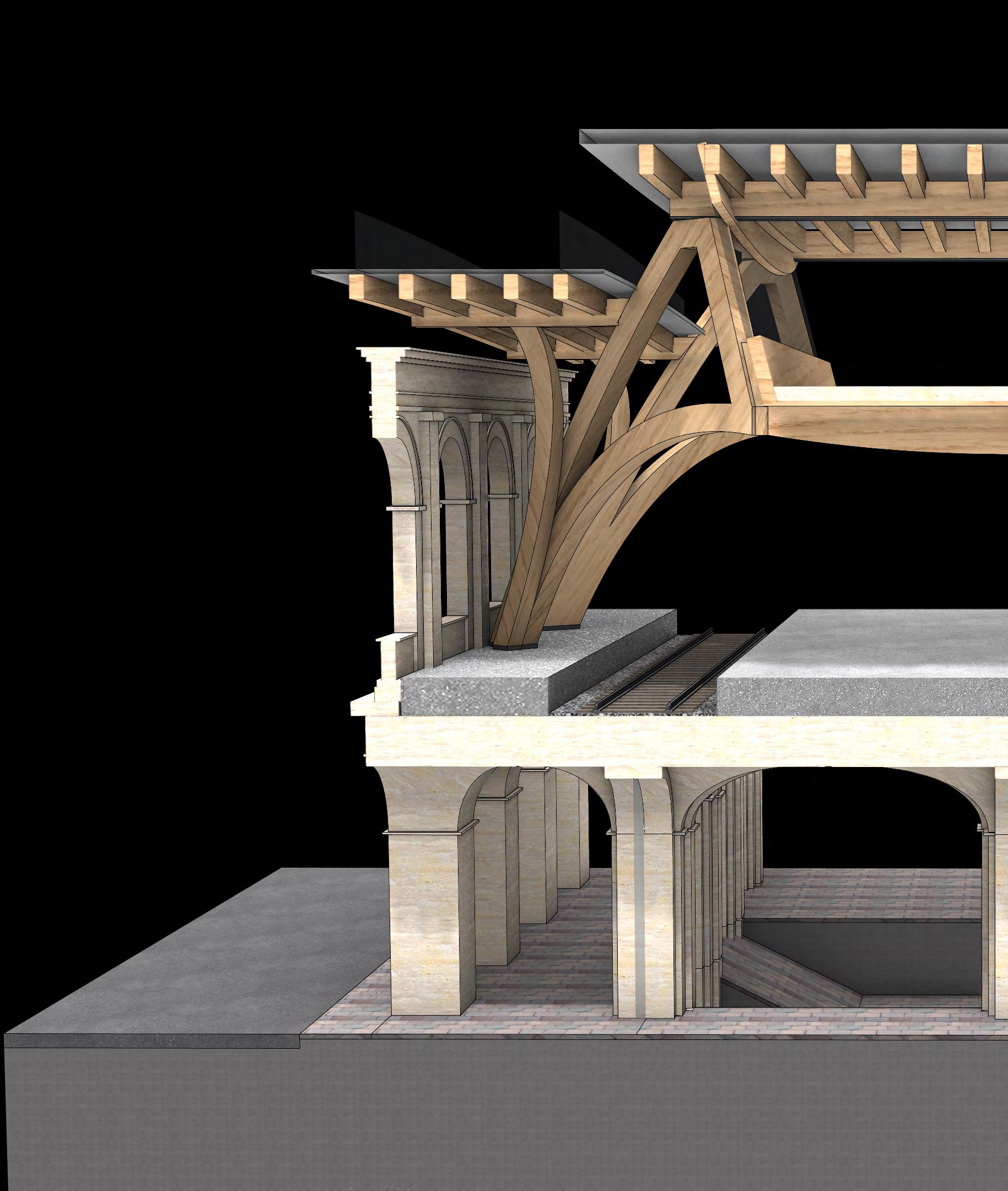
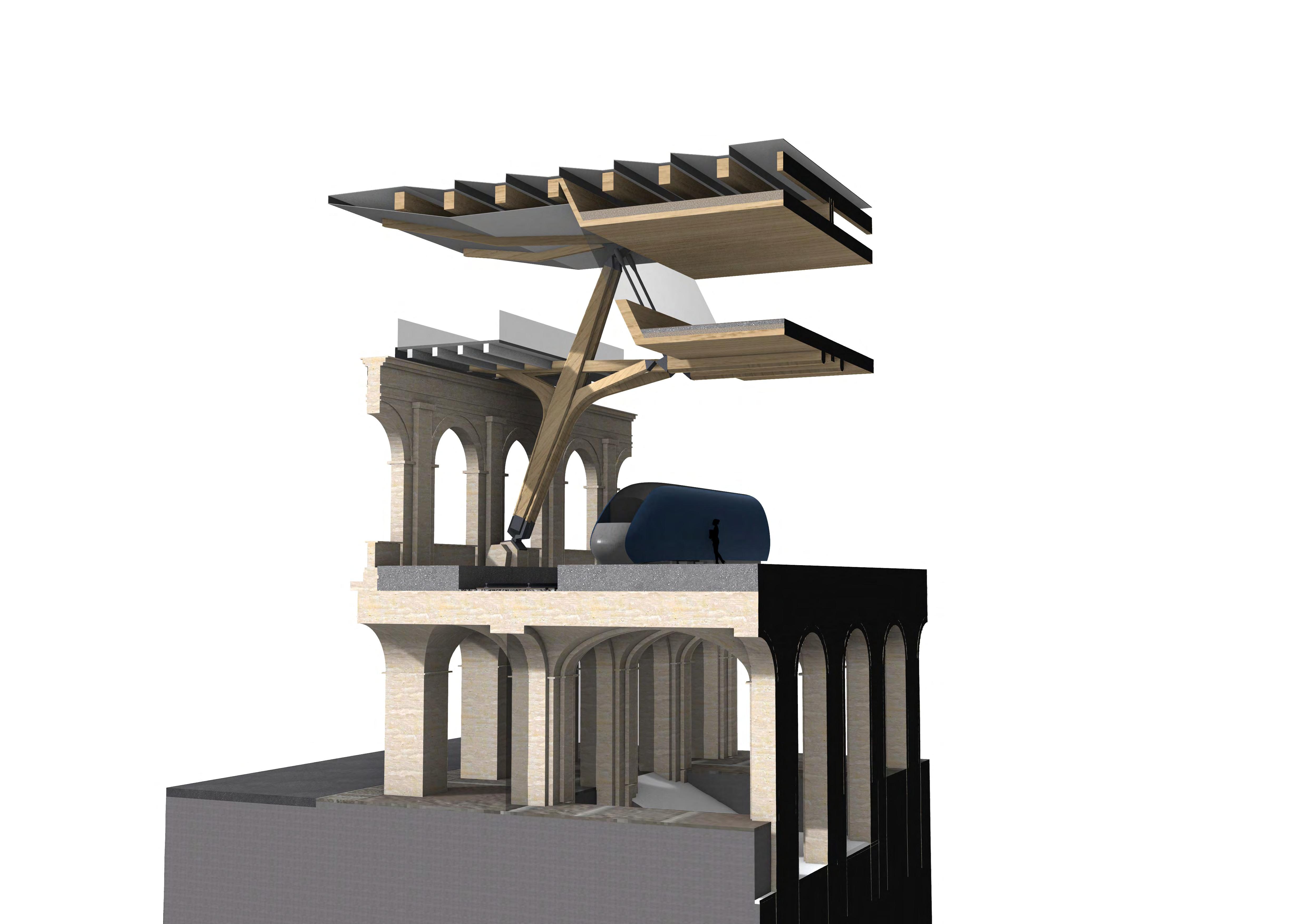
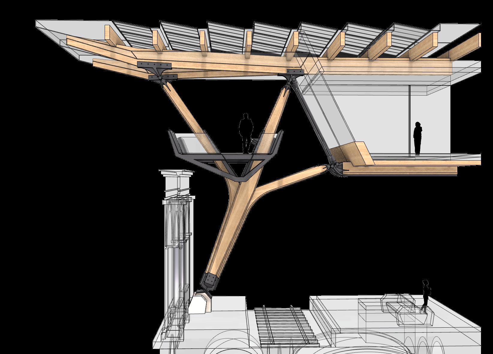
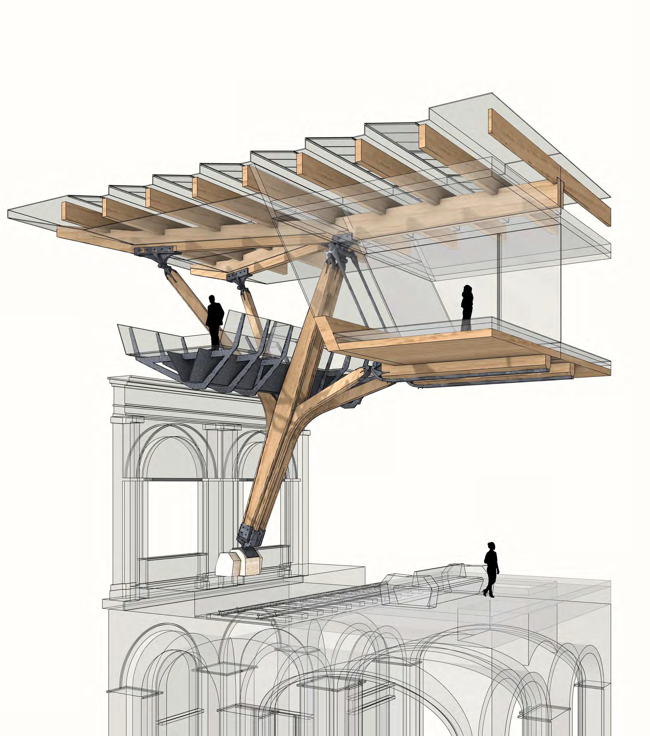
The final structure reconciles the issues of fitting program above train track, building within existing façades and integrating a terrace with a rational yet expressive language.
Mezzanine Structure Fragment
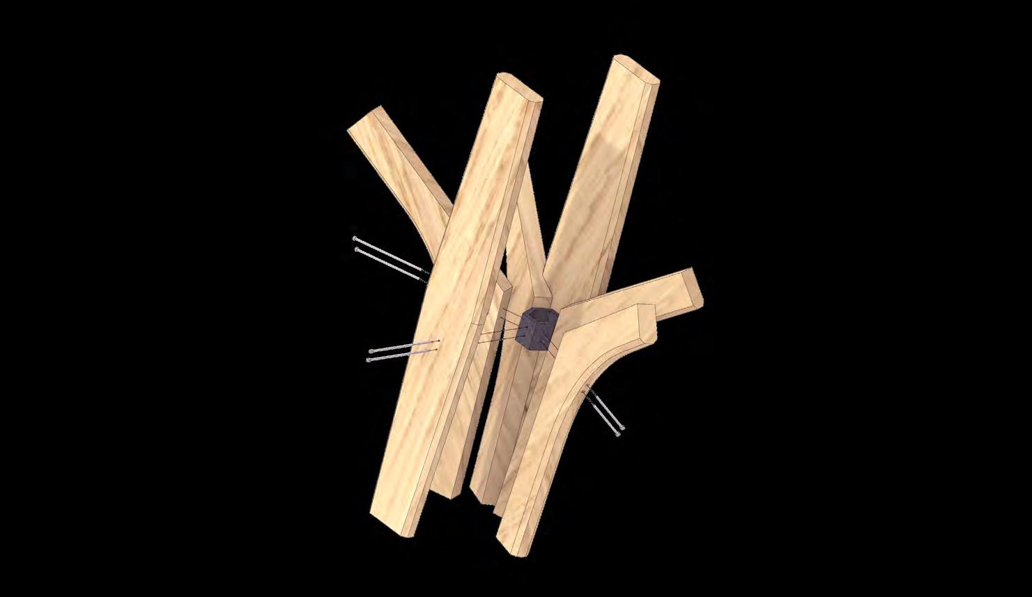
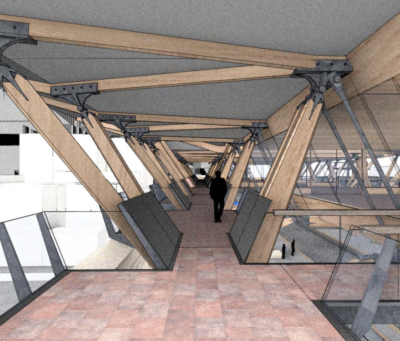
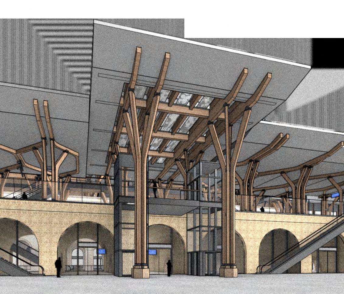
The tree form of the column is more distinct, with the walkway structure inlaid between the members. It acts as a different system which contracts in the column frames and then expands out to create terrace spaces.
The column cruves around the façade and meets the roof and mezzanine structures at
Seating within the Base
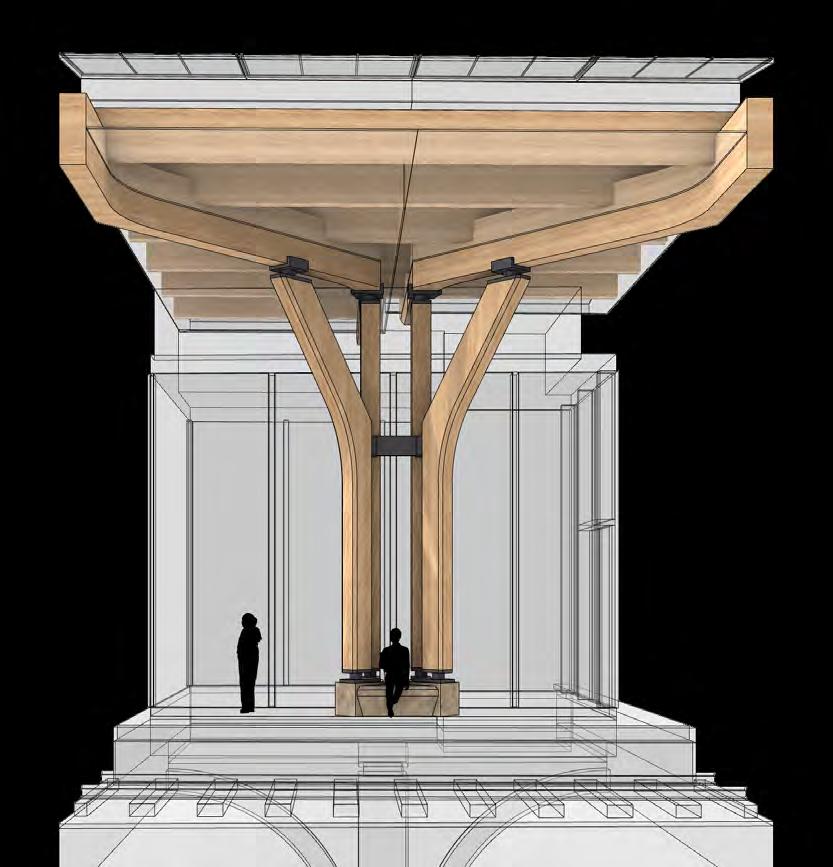
The columns radiate up from the seat, framing the person seated in an elevated moment.
Canopy Structure Fragment
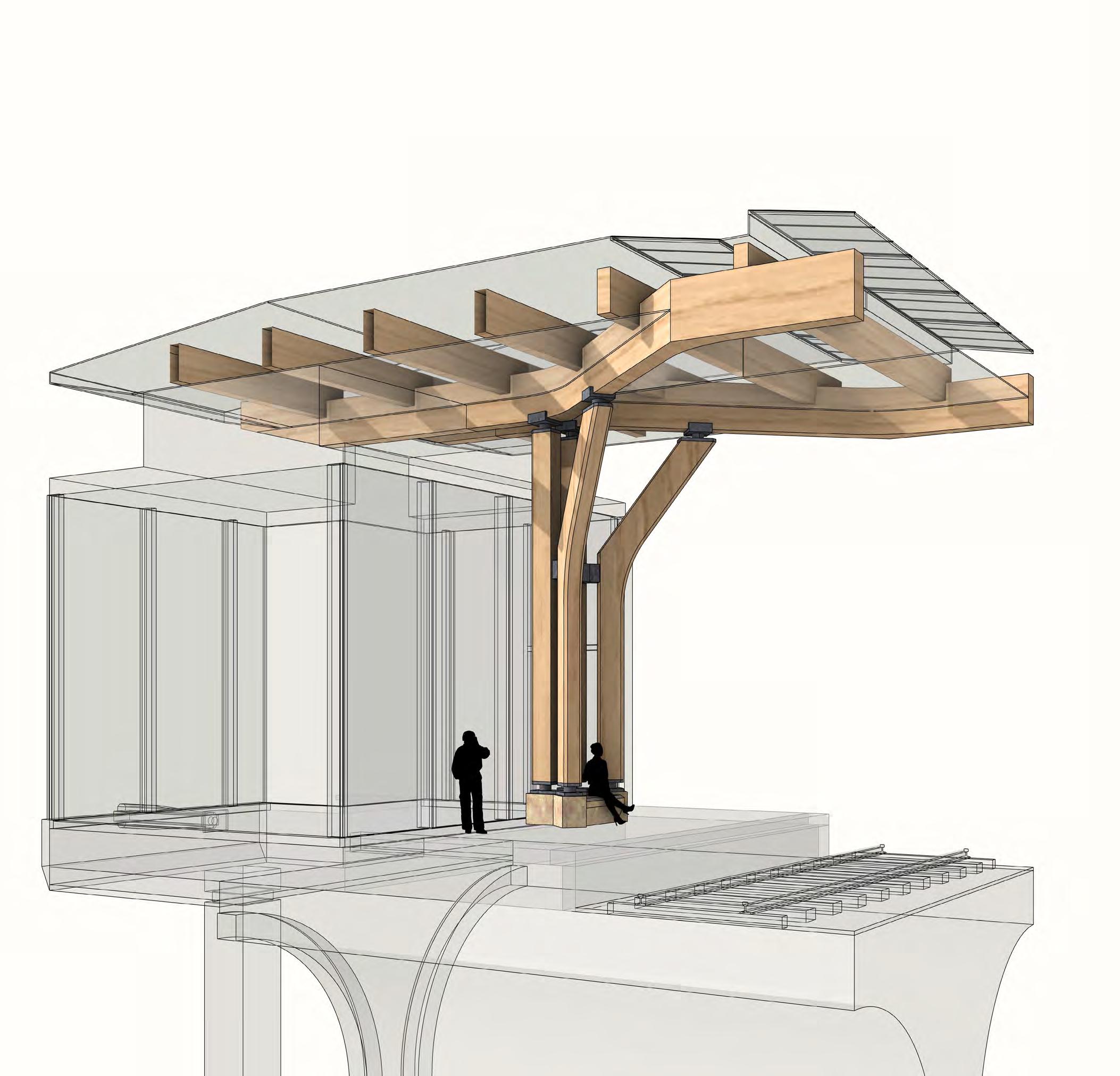
The columns lean diagonally to align with the roof diagrid beams. they also create a triangle frame to resist moments.
Structural System - Central Module
By the central terrace, the structural frame must adapt for the raised roof and to guarantee the stuctural stability of the wider spans. New columns are added to expand the module into a second direction of spanning.
Central Terrace Fragment
Additional column members are extended to a higher roof in the middle spanning along the platforms.
Central Terrace
The column members frame the central terrace and the view it projects towards. They lean more in the middle, creating a bottleneck before the access to the balconies.
Structural System - Joinery
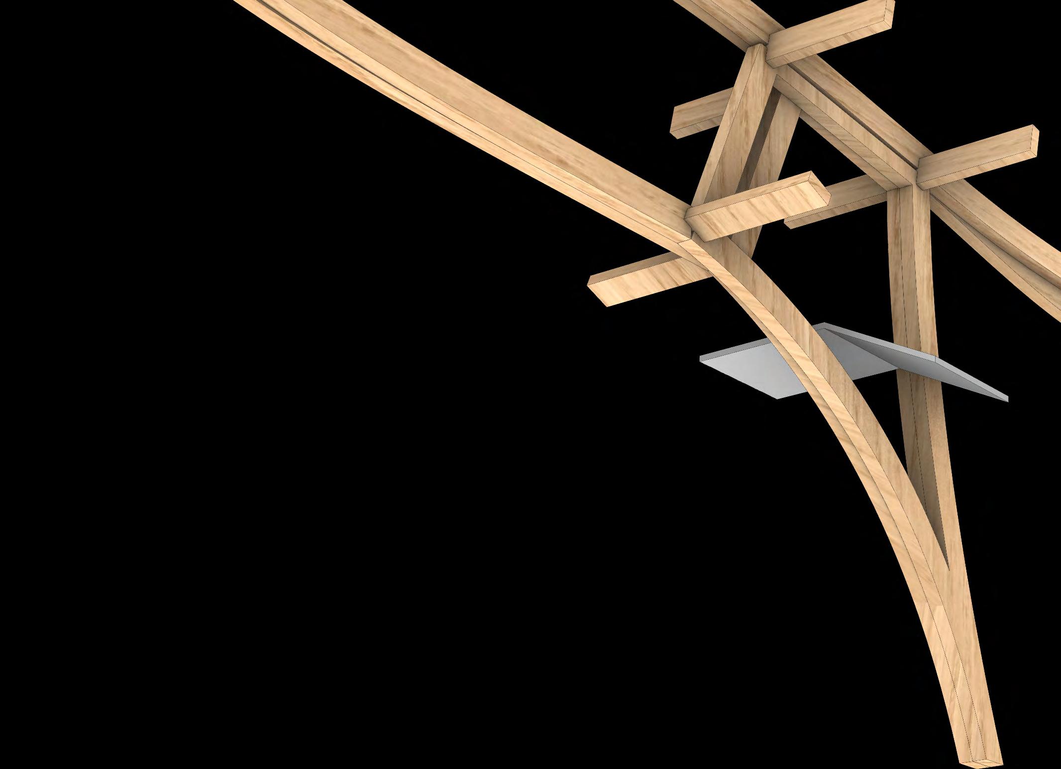
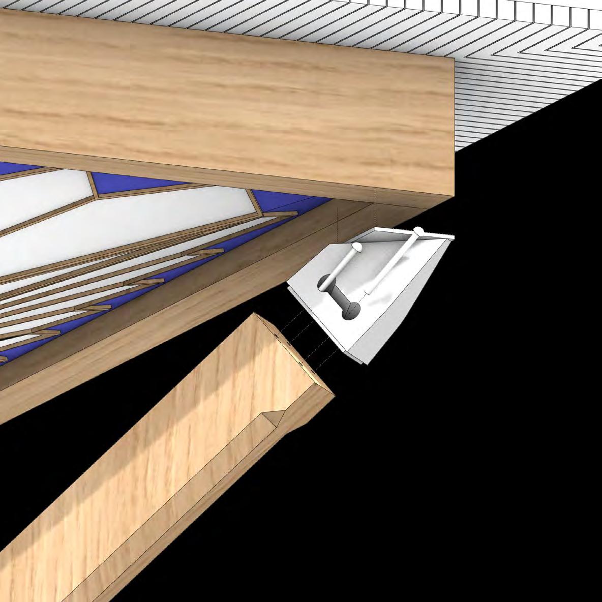
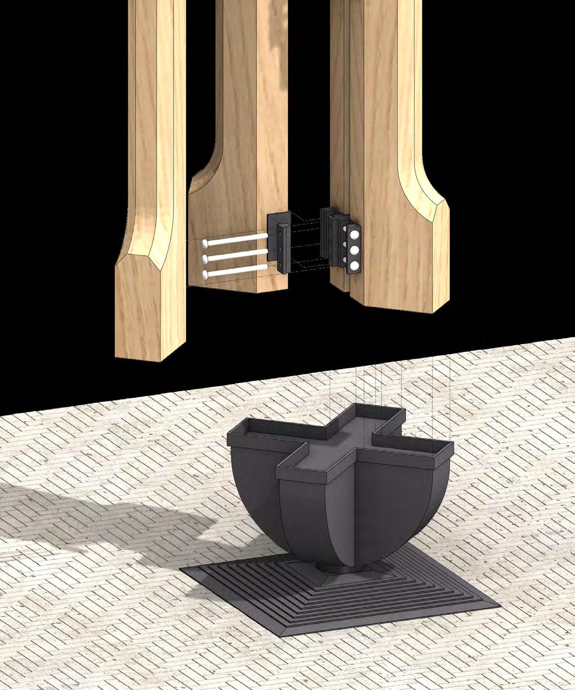
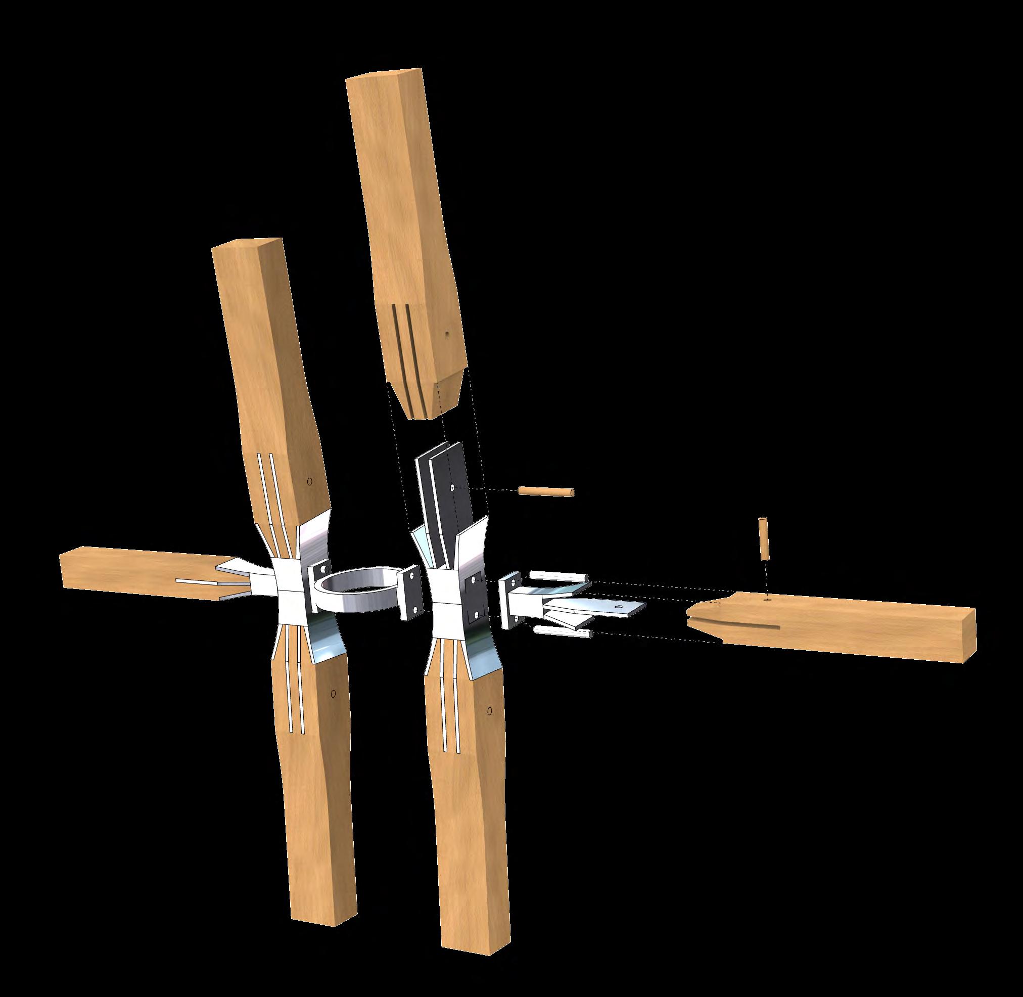
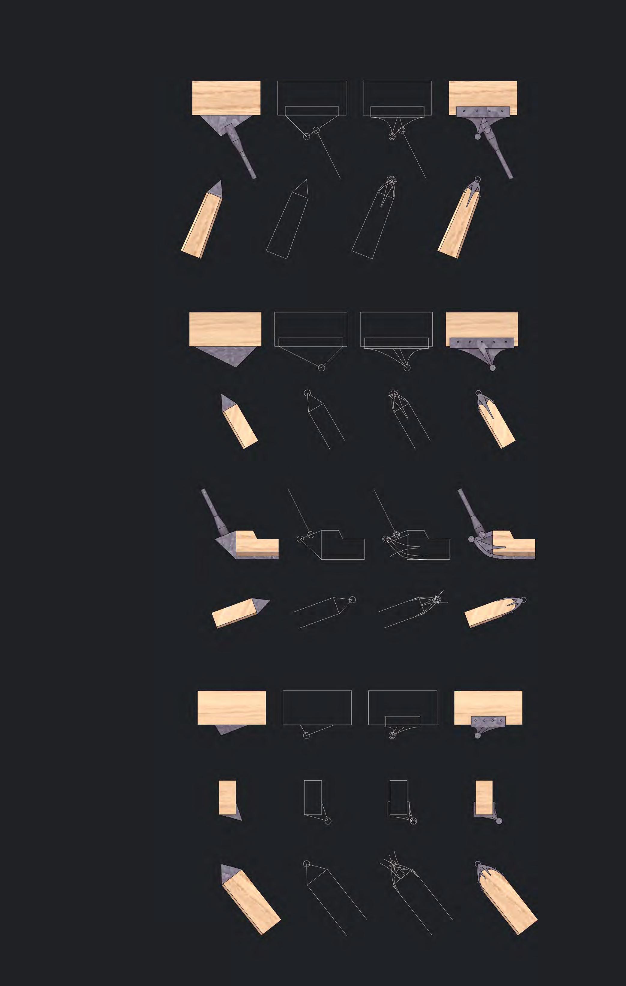
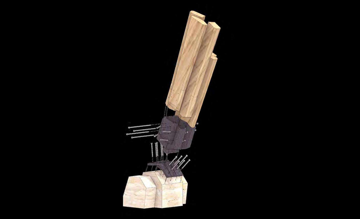
The North Frame involves extensive steel joinery methods, nesting timber members within sculpted steel shapes. Two languages are implemented to contrast the base and the tips of the structure.
Joinery Catalogue
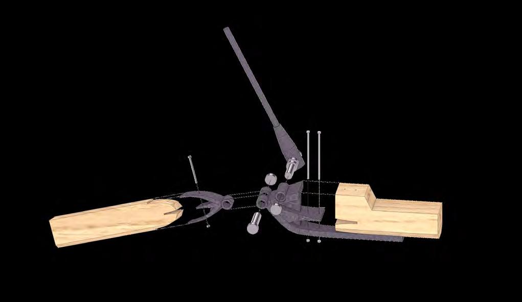
Each steel pin and finger joint is constructed based on the draft geometries and the load conditions.
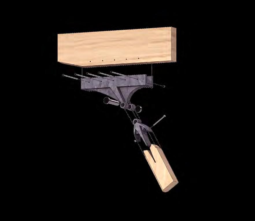
Top Main Joint
Side Joint
Top Side Joint
Top Joints for the Central Terrace
The
Top Main Joint
Two
of
come
The casing is wide and massive, to represent the cummulated loads. It ends witha pinned roller bearing which is
sets
pins
together in the connection, which is attached to a flitched beam of the roof.
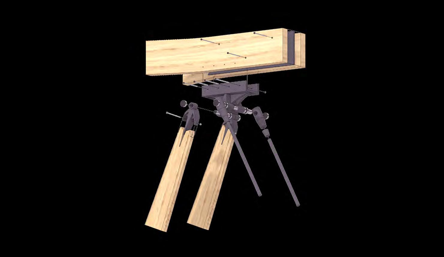
Side Joint
The mezzanine floor beam is reinforced by a steel strip which integrates with the steel connection to resist bending.
Inner Ring
All the column members converge to that ring, which takes in the compression forces. The connection is hidden to imply a node.
Base Joint
nested into the stone base.
Top Side Joint
roof beam overhanging is supported by the side column through a simple U bracket and pin joint.
Canopy Roof Fragment
The columns come in clusters of 4, framing the seating on their stone base and radiating up to the diagrid of beams.
Building Proposal
A collection of rendered views to describe the project form and narrative.
Aerial View
Façade View
Central Axis in the Entrance Hall
Garden by the Platform
Arcade Gallery Niche
Back Entrance
Rooftop Terrace
Escalators to the Platforms
Environmental Short Section
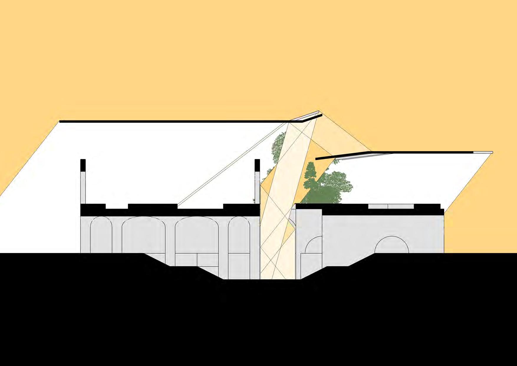
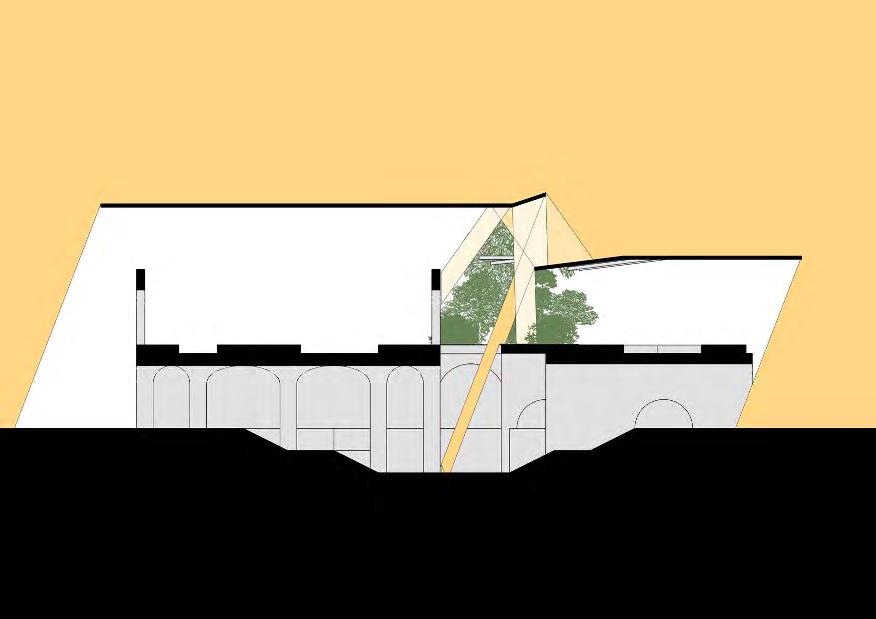
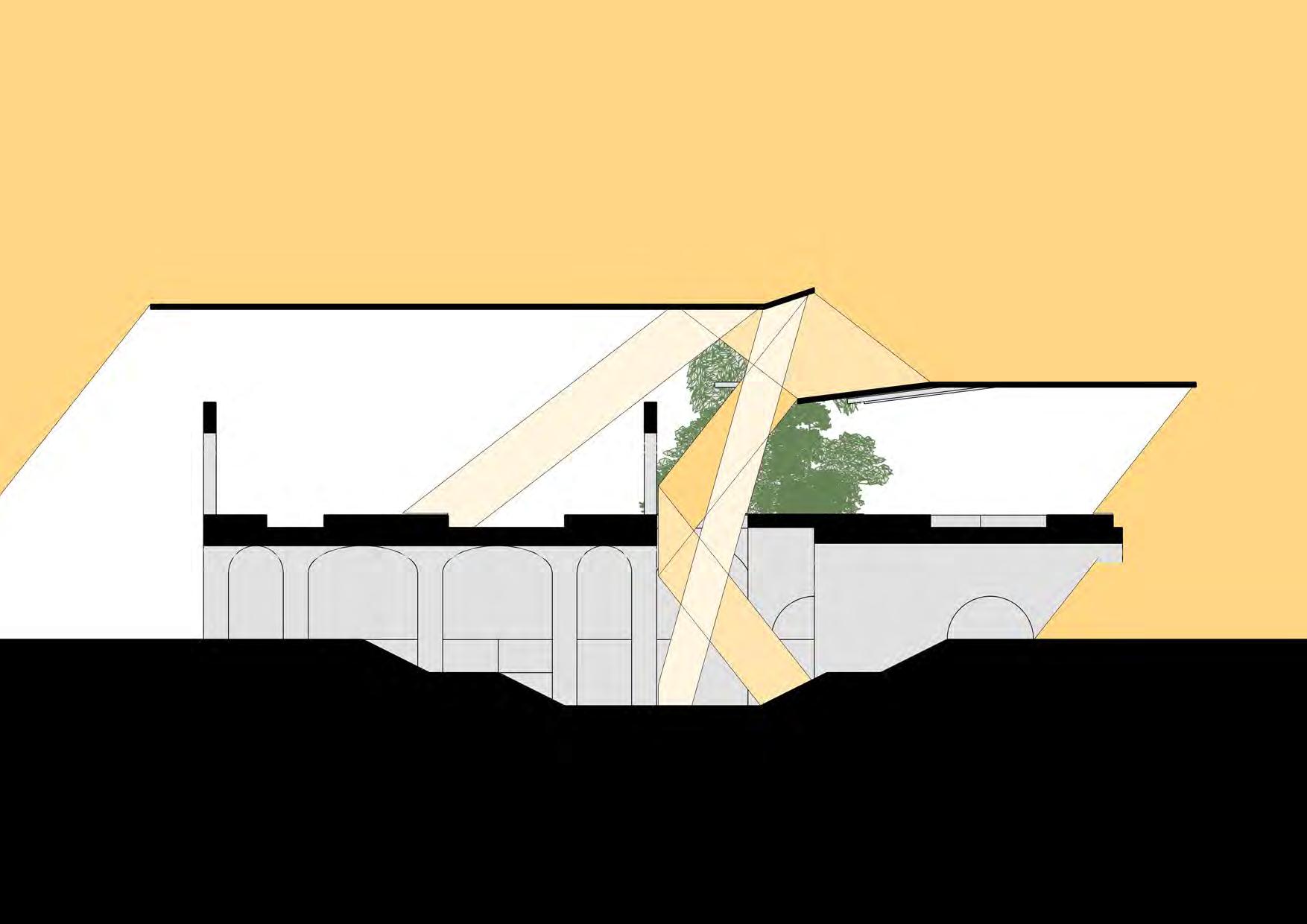
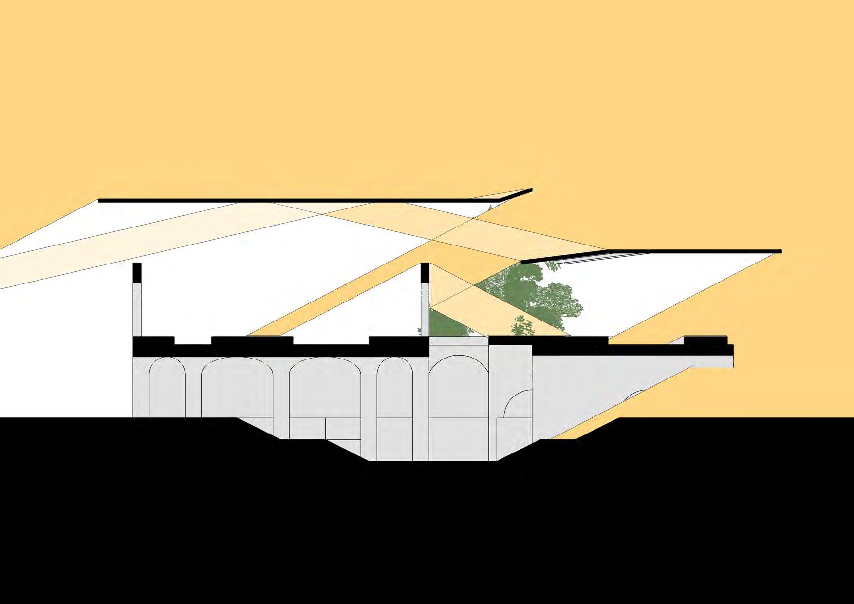
The roof overhangs were sized to minimise the solar impact on the platforms, mitgating overheating and glare. The building is mainly naturally ventilated. However the restaurants are equipped with mechanical ventilation embedded in the roof.
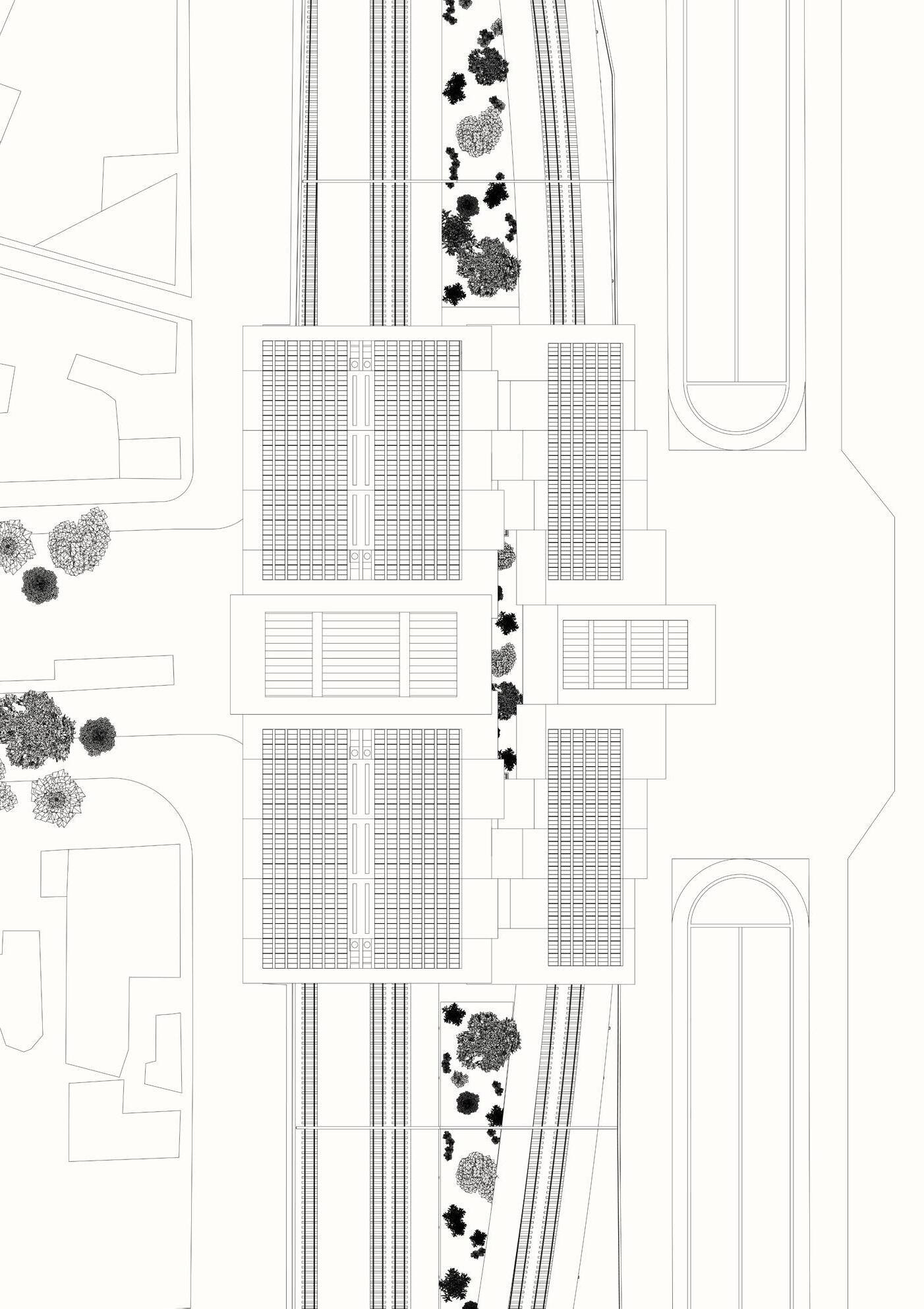
General Arrangement Drawings
Technical drawings of plans and sections of the building proposal.
Legend
1. Rooftop restaurant
2. Terrace
3. Restaurant lobby
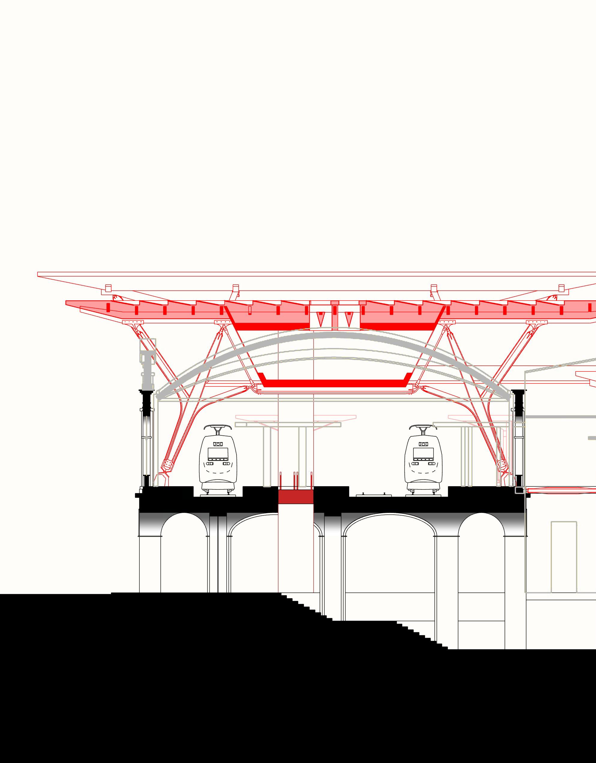
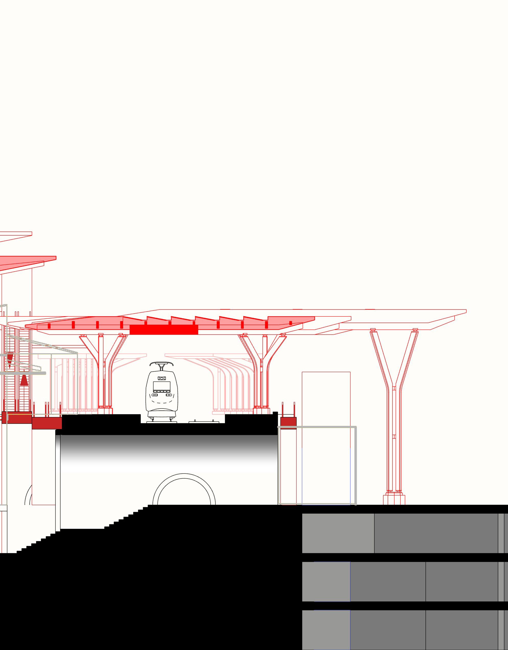
CAD Drawing - retrofit Short Section - 1
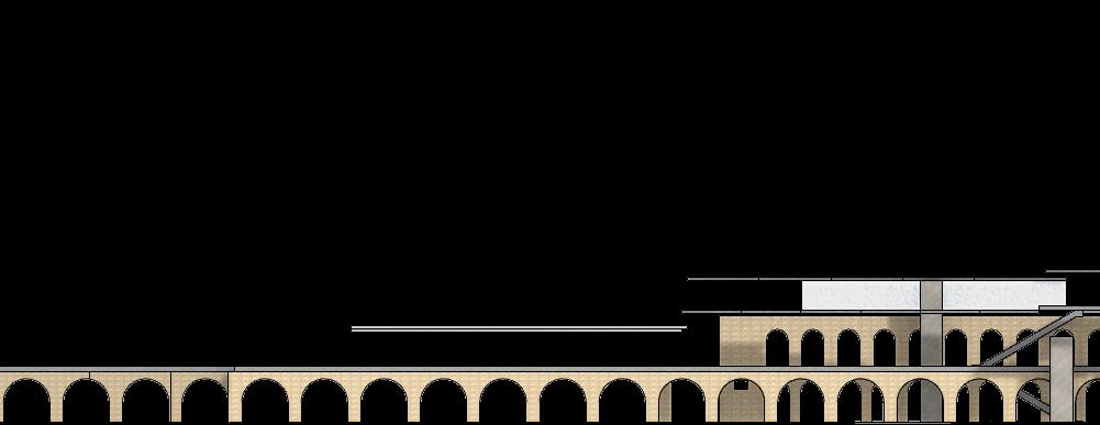
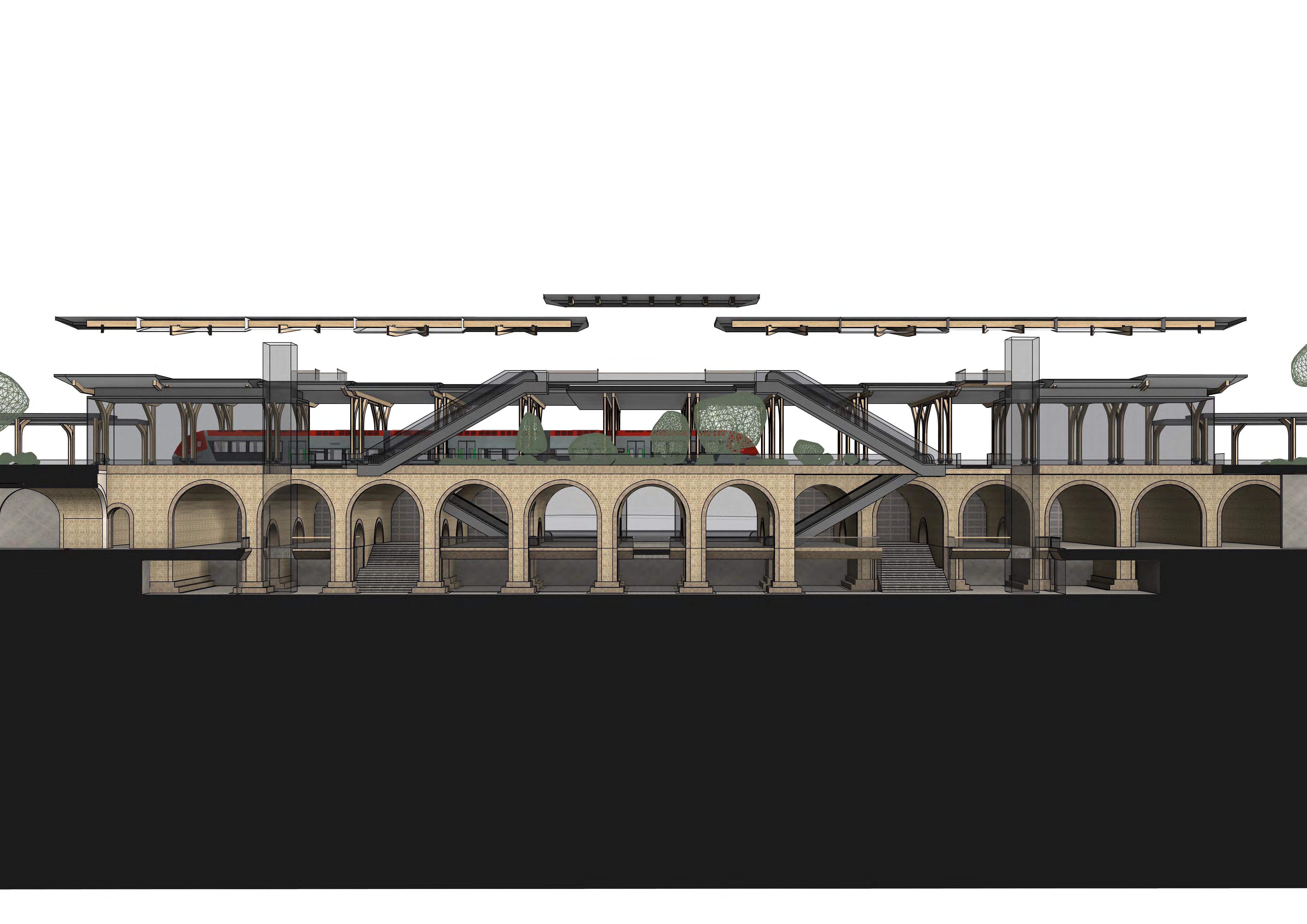
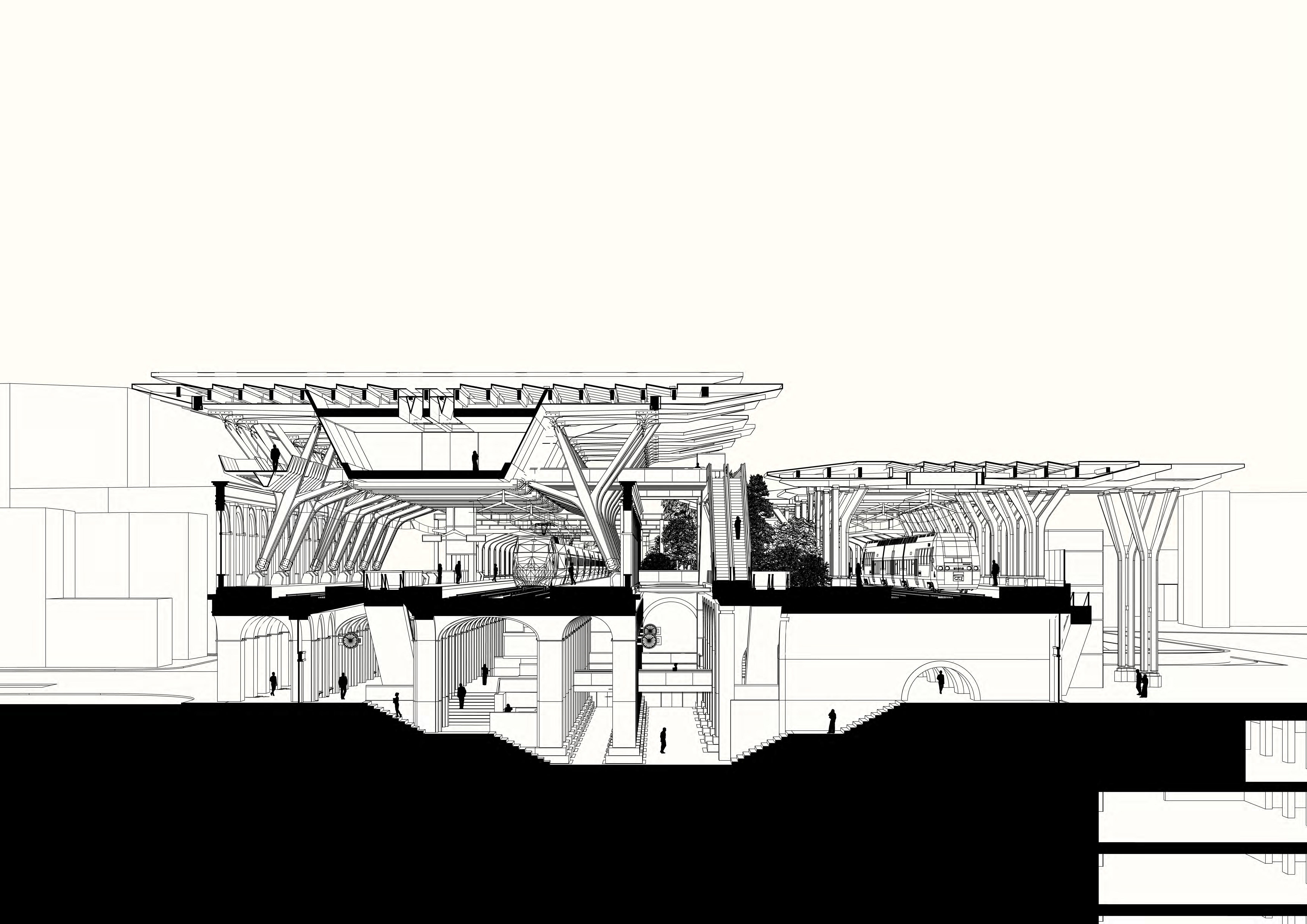
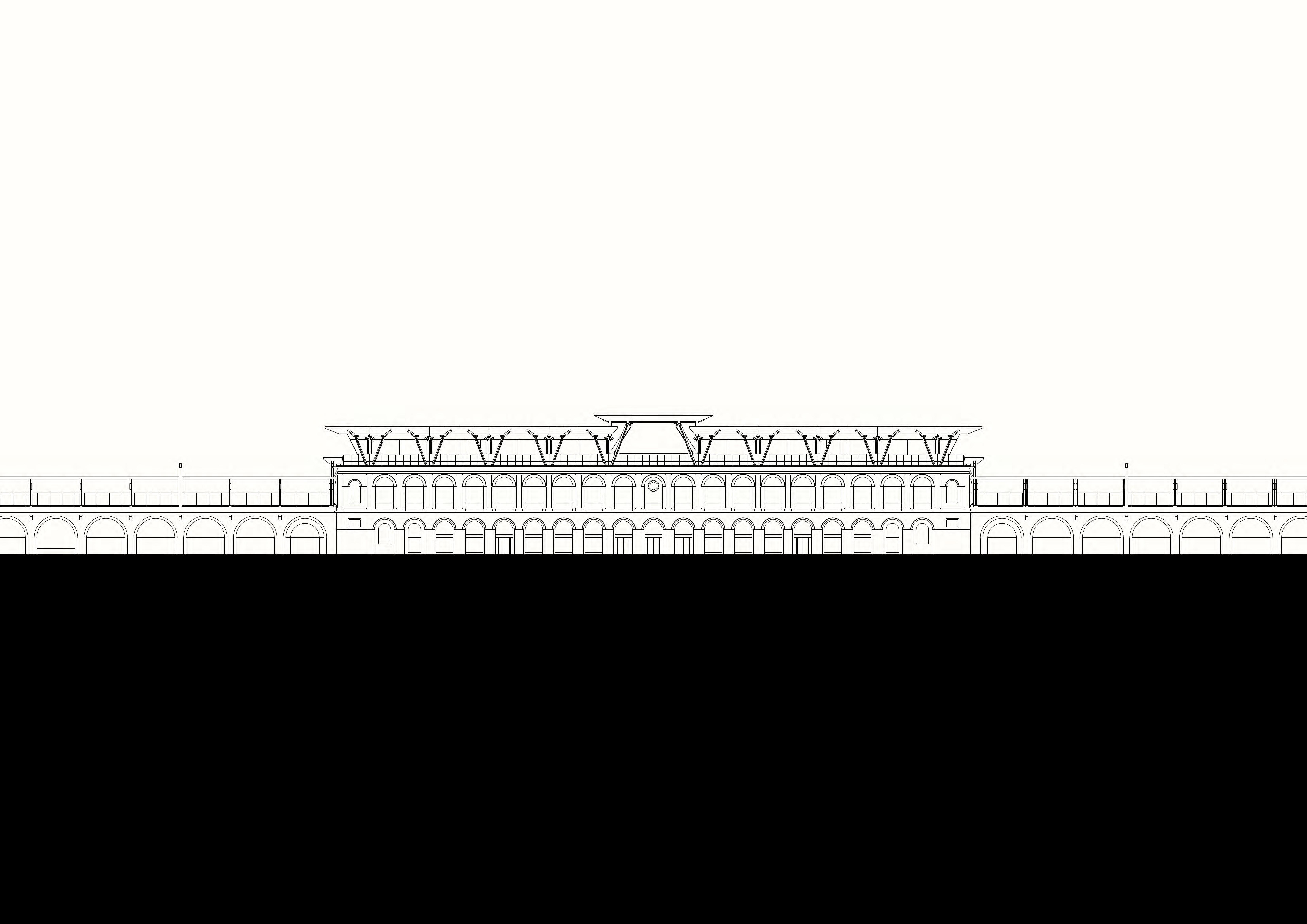
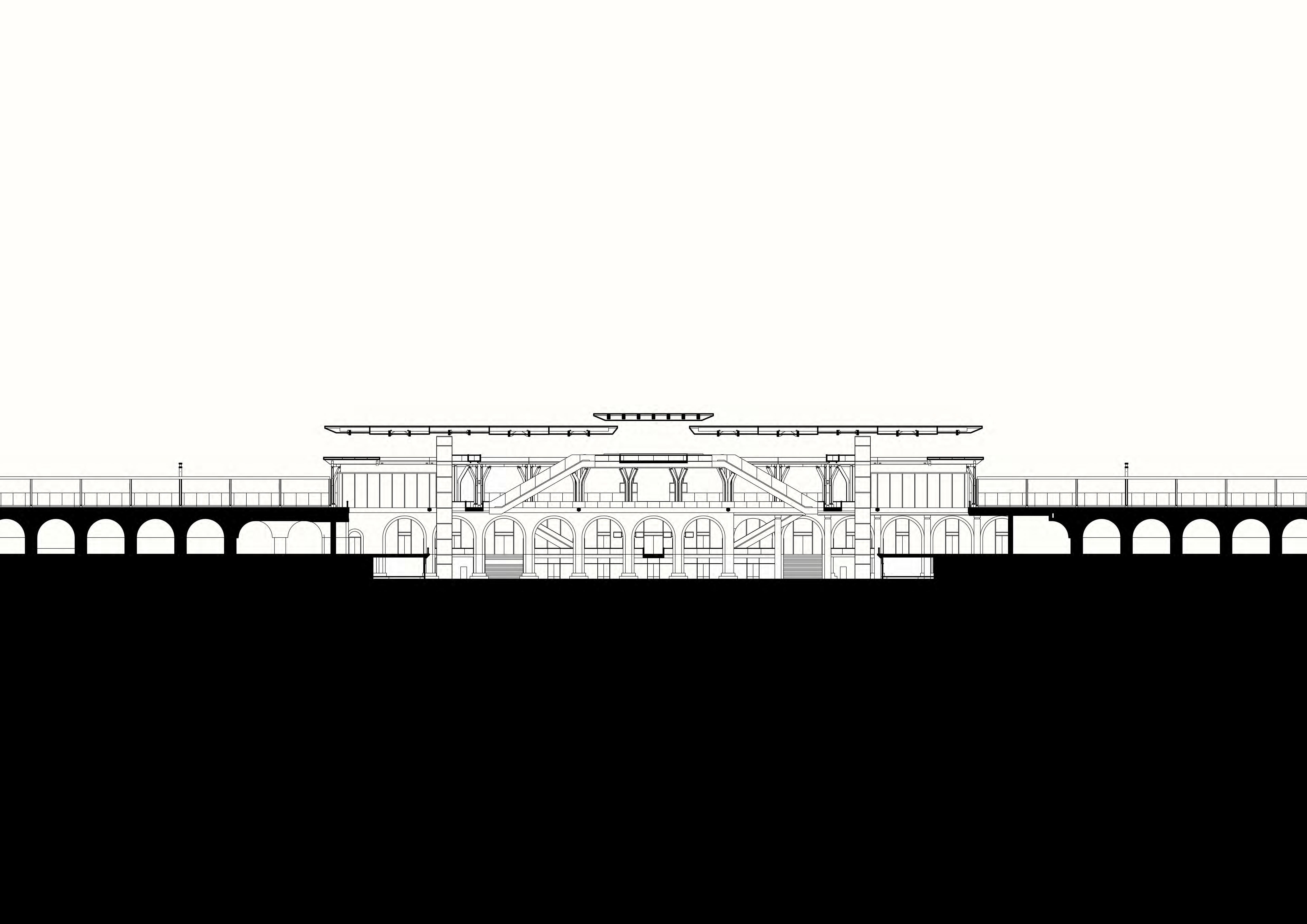
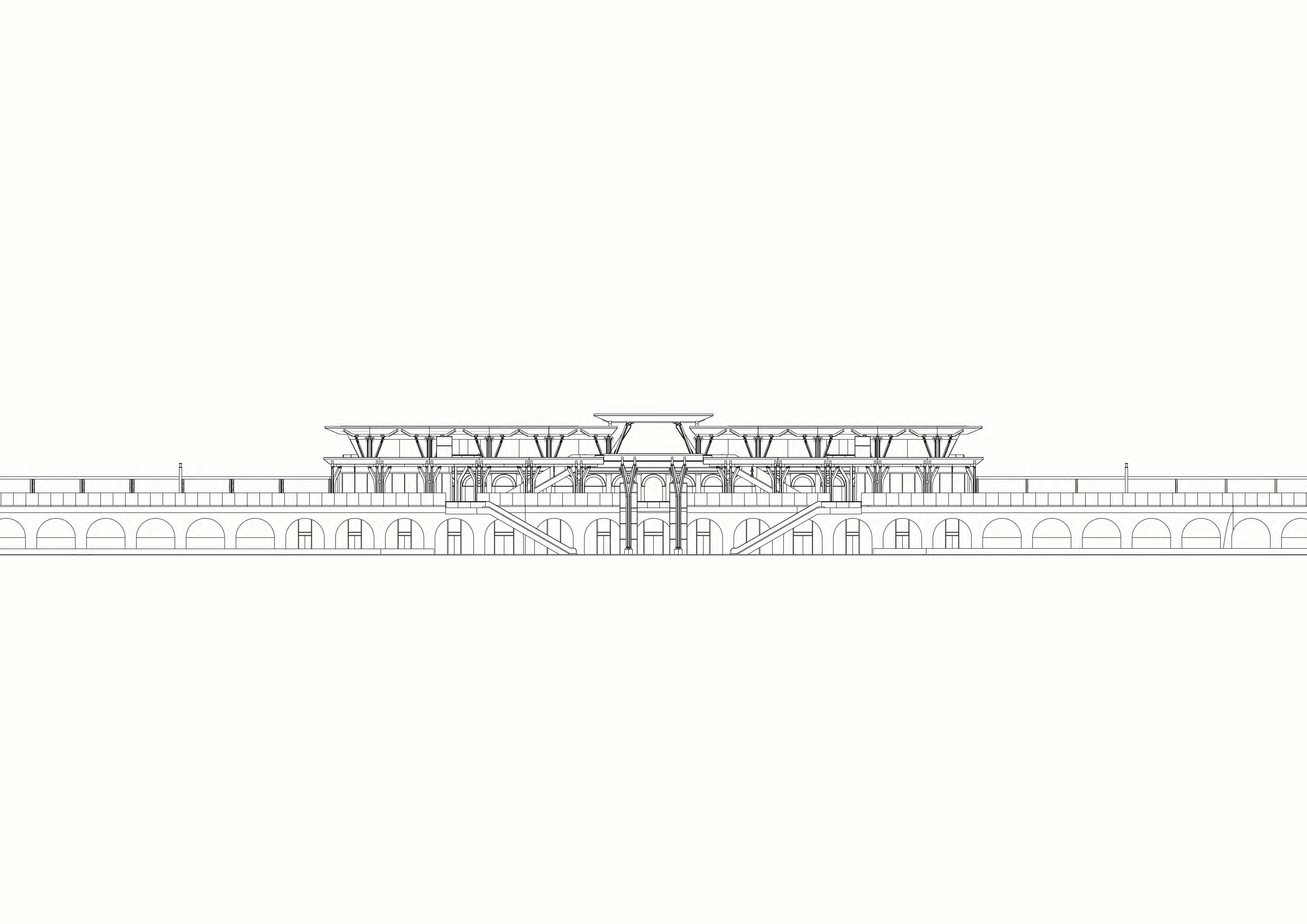
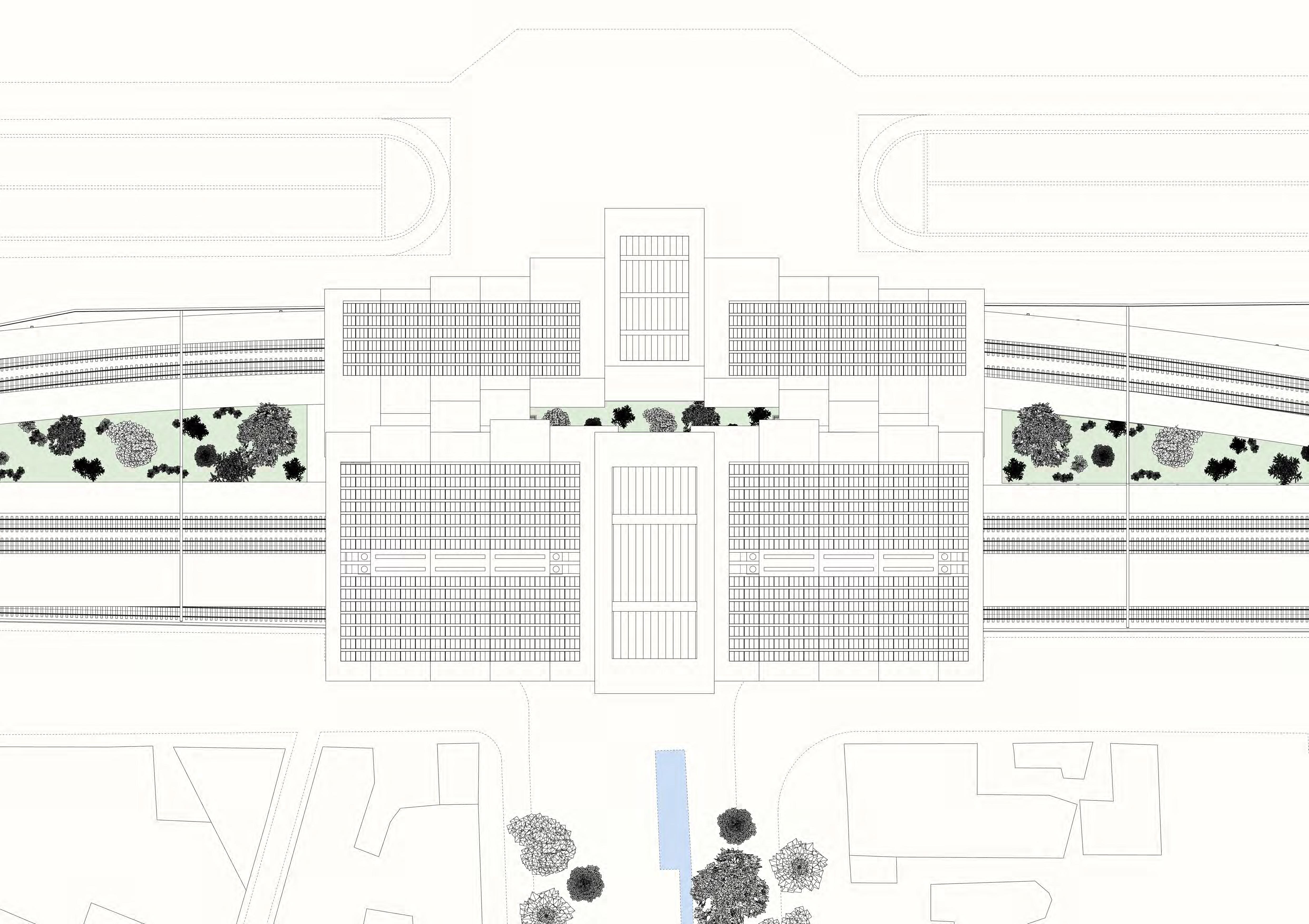
The section depicts the removed elements from the existing viaduct, as well as the new intervention. It shows how the roof height is raised by a minimal amount, while fitting new program. The atrium is cleared out for more distinct massing typologies.
Appendix
A collection of exercises that did not yield further work.
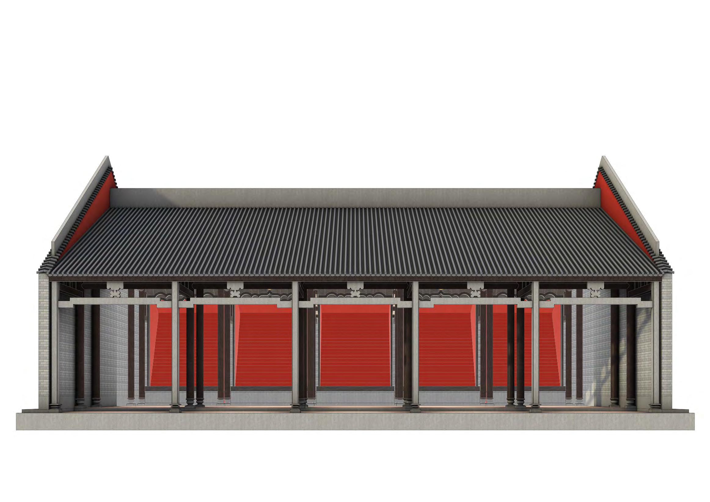
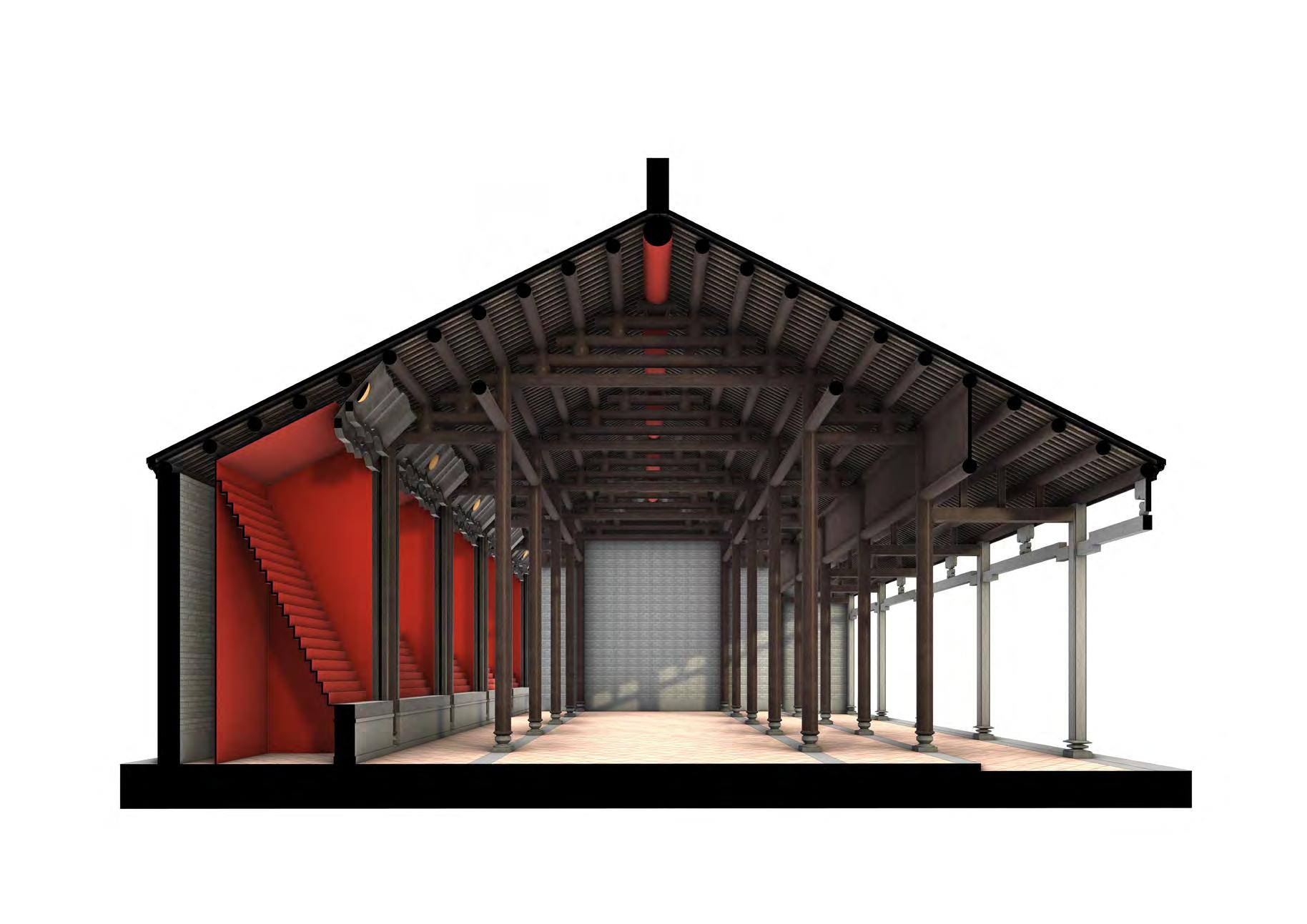
The Chen Clan Ancestral Hall was built in 1894. It is composed of three main halls of similar proportions seperated by courtyards. The halls are built with timber frames and flush gable roofs, examplary of Cantonese hall-type timber structures. This includes mortise and tenon joinery for
Back Hall Elevation
The façade is divided in five sections by series of pillars. The front pillars are made of stone for weather resistance. Each section leads to an altar where the names of the Chen families are displayed.
Back Hall Section
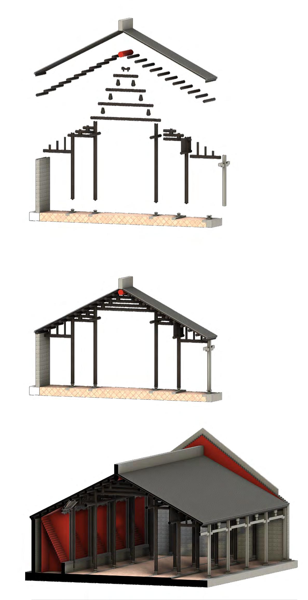
The series of pillars support stacked beams parrallel to the width of the building, against the weaker direction. The reinforcements being under the roof allows for slimmer pillars and a more open space.
Exploded Diagrams
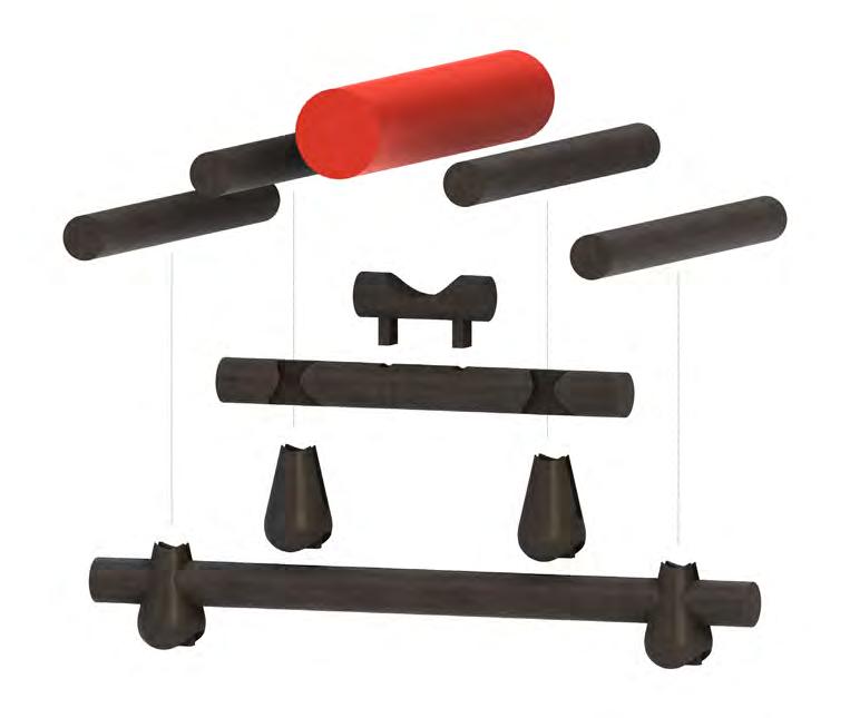
The pillars and beams connect with strut-beam system of mortise and tenon joinery. Those tight connections with no nails give some flexibility to resist eathquakes. The pillars are laid on narrow stone foundations to minimise corrosion from humidity. The system is also modular, allowing for the replacement of disused elements.
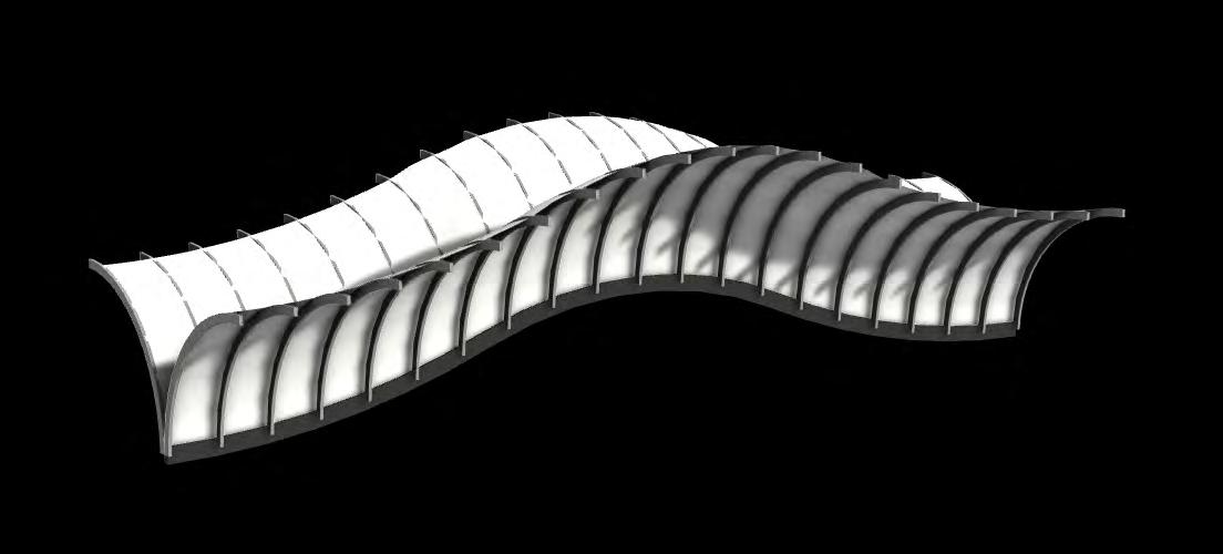
Iterations - Twisted Tectonics
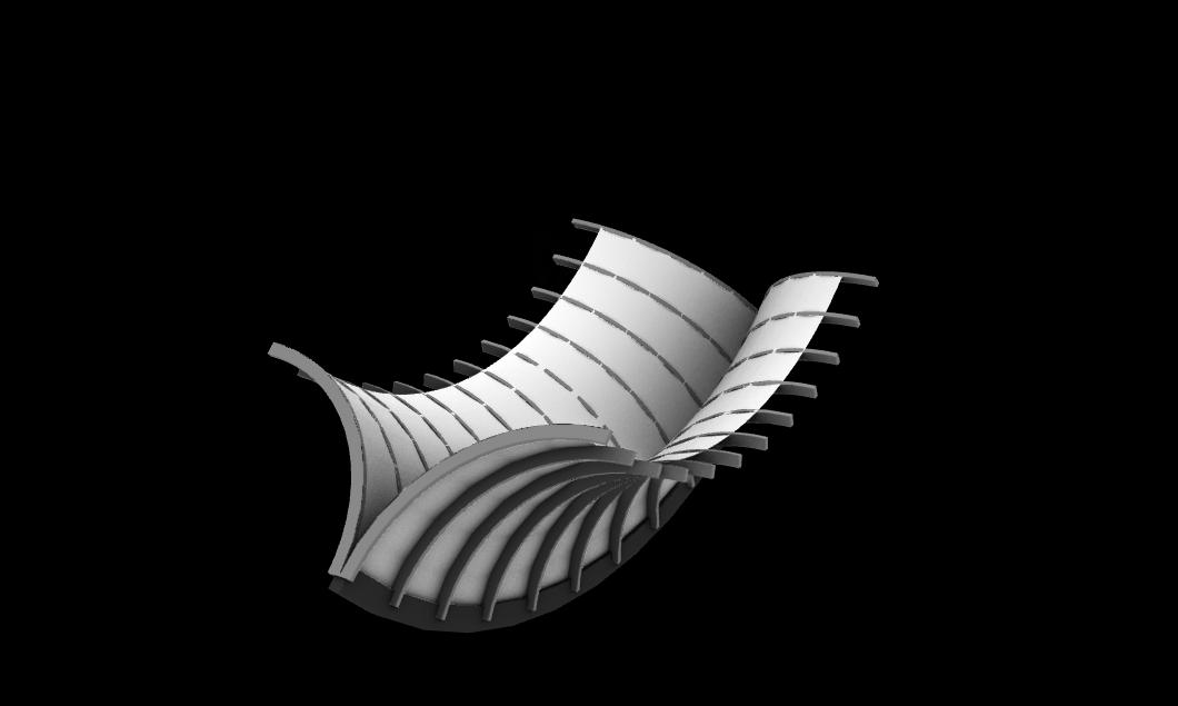
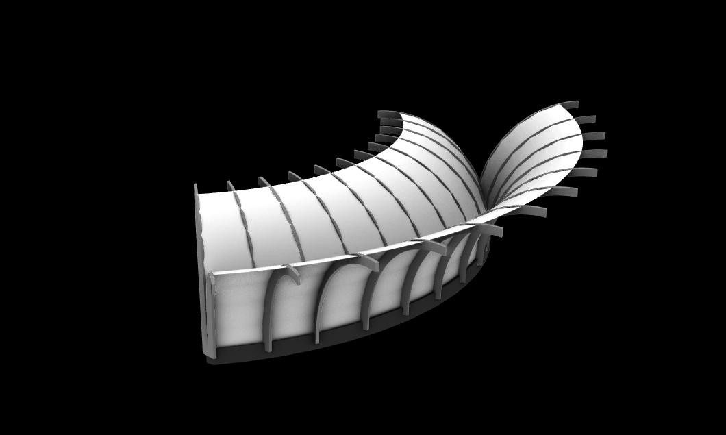
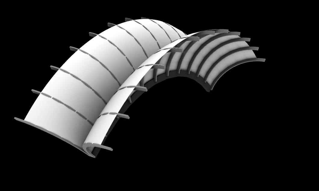
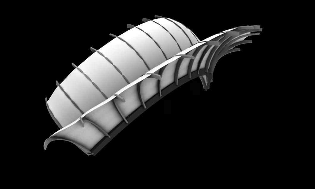
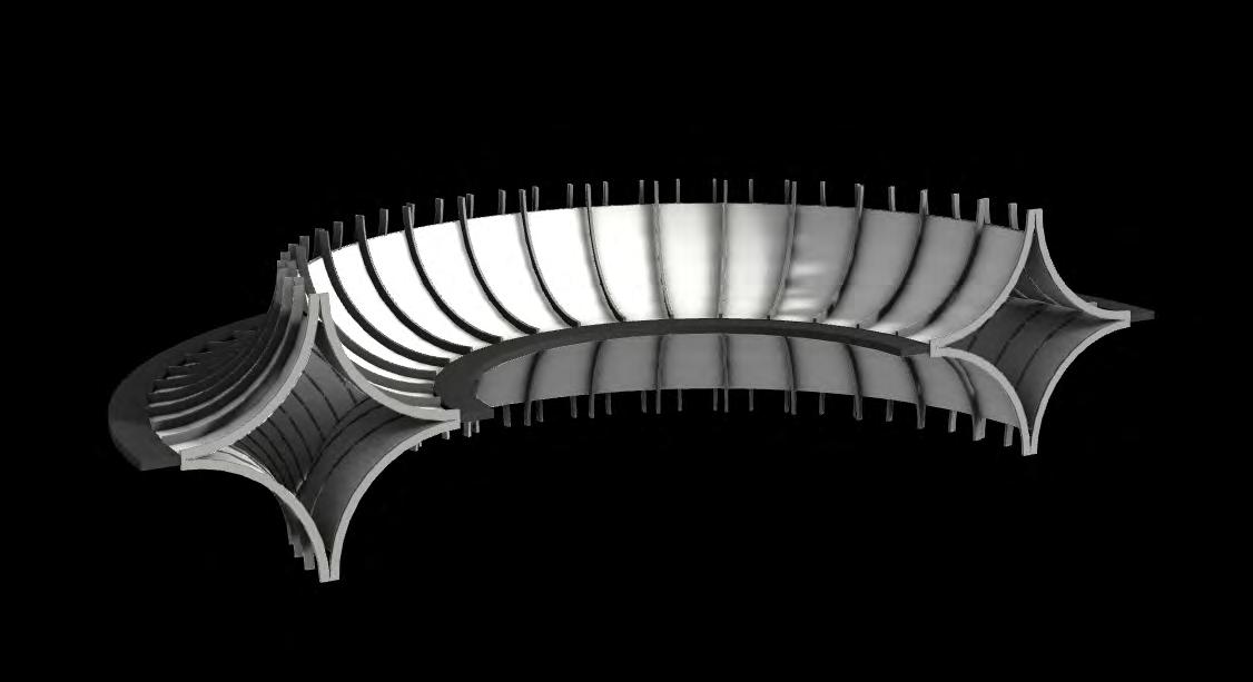
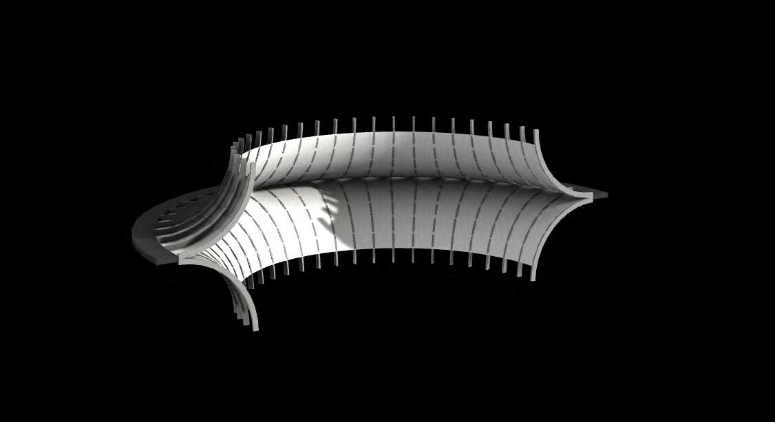
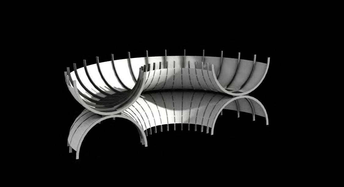
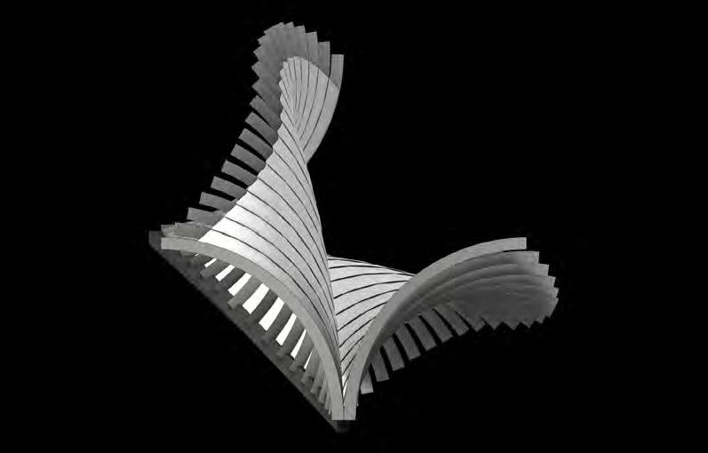
The following iterations explore how altering the curvature and orientation of the spine creates membranes, structures and spaces.
1. Bridge Iterations
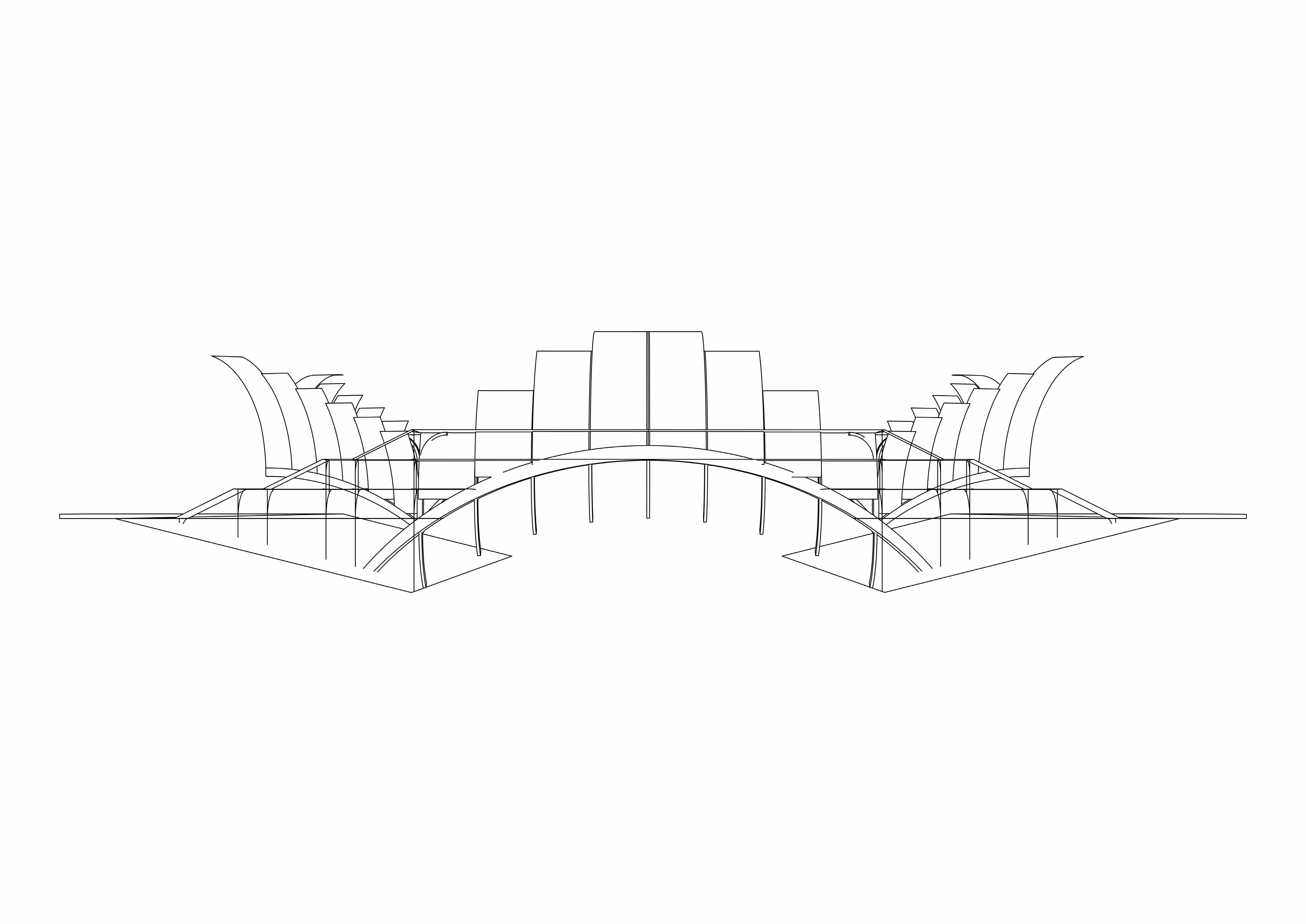
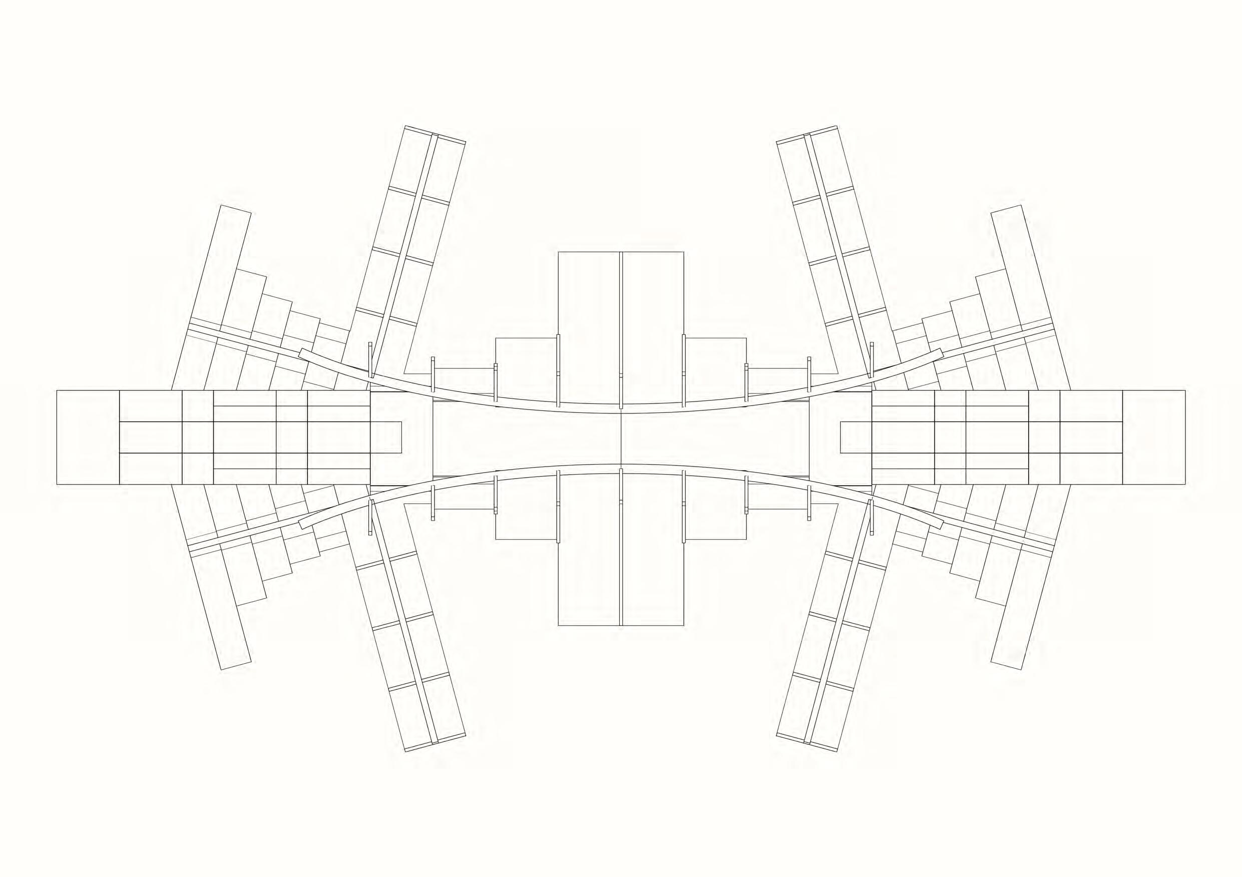
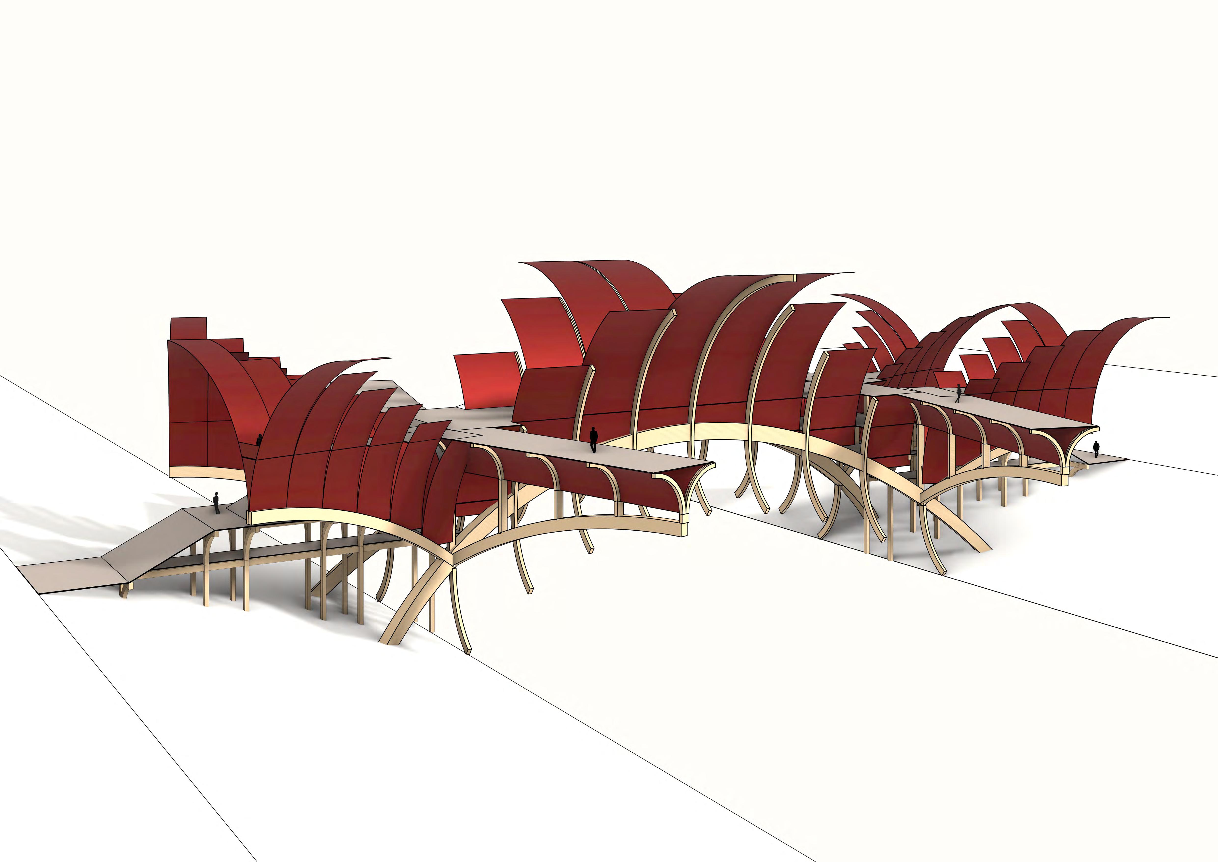
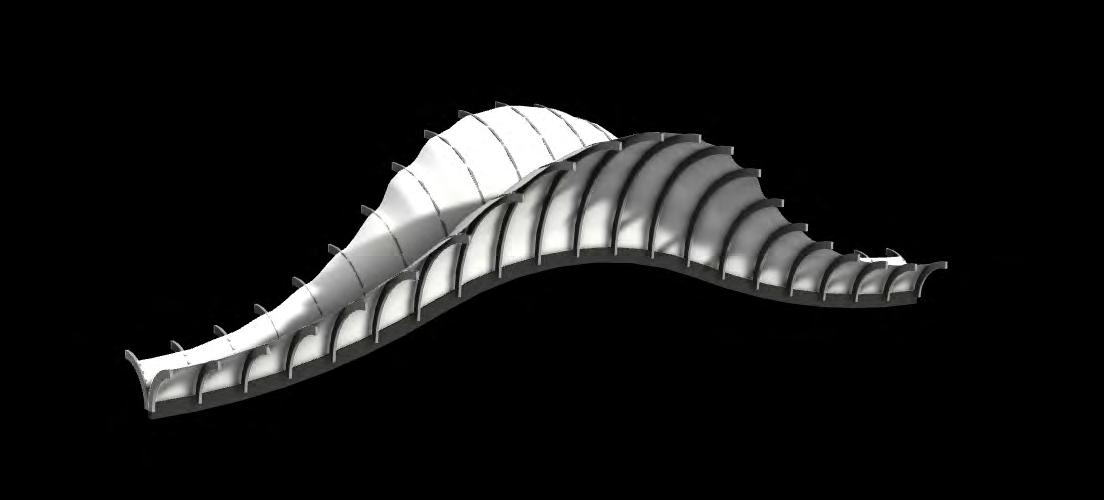
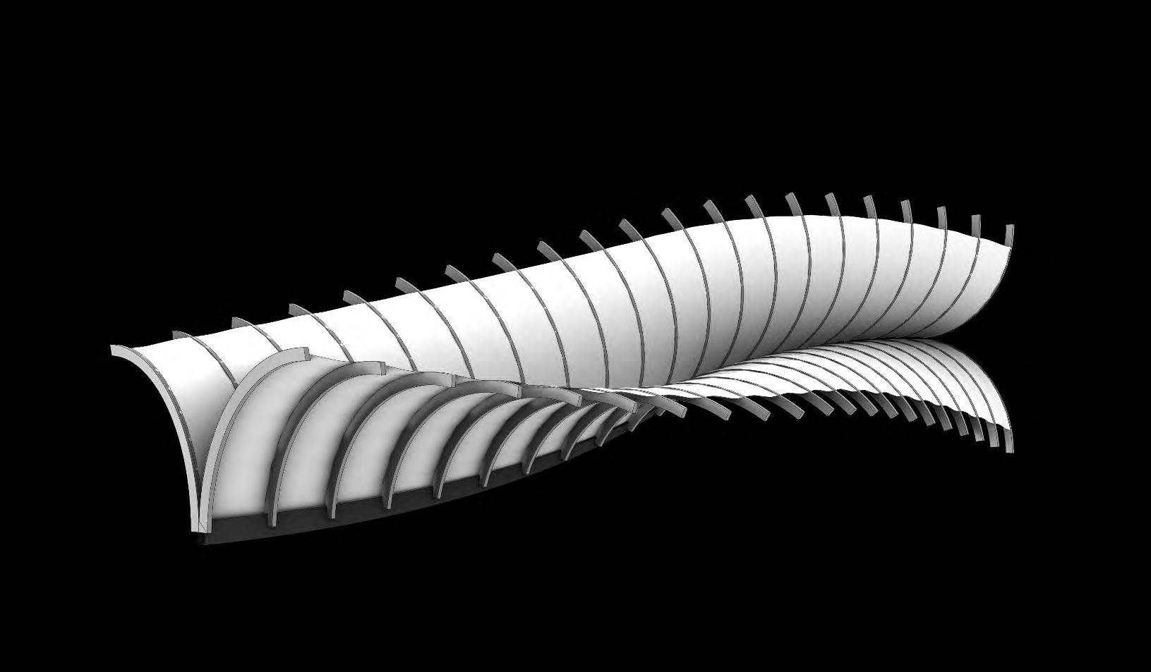
The spine follows a hump curvature and the arches take variable radii along the its length. The crease between the arches is the channel for circulation.
2. Embrace Iterations
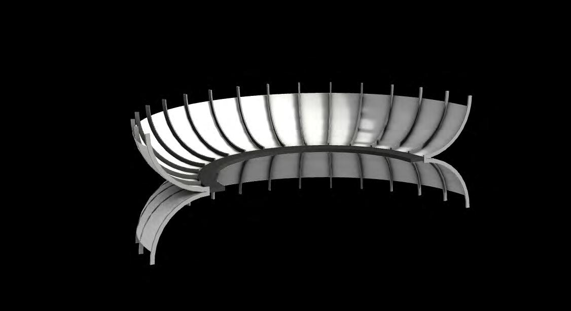
The spine becomes a horizontal arc. The arches are now fliped to the side. The spine acts as a circulation platorm.
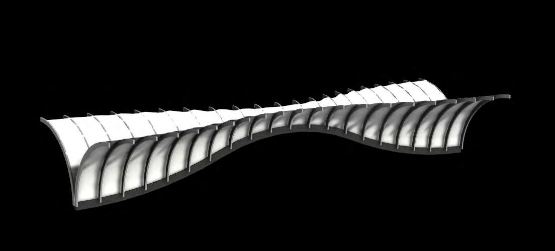
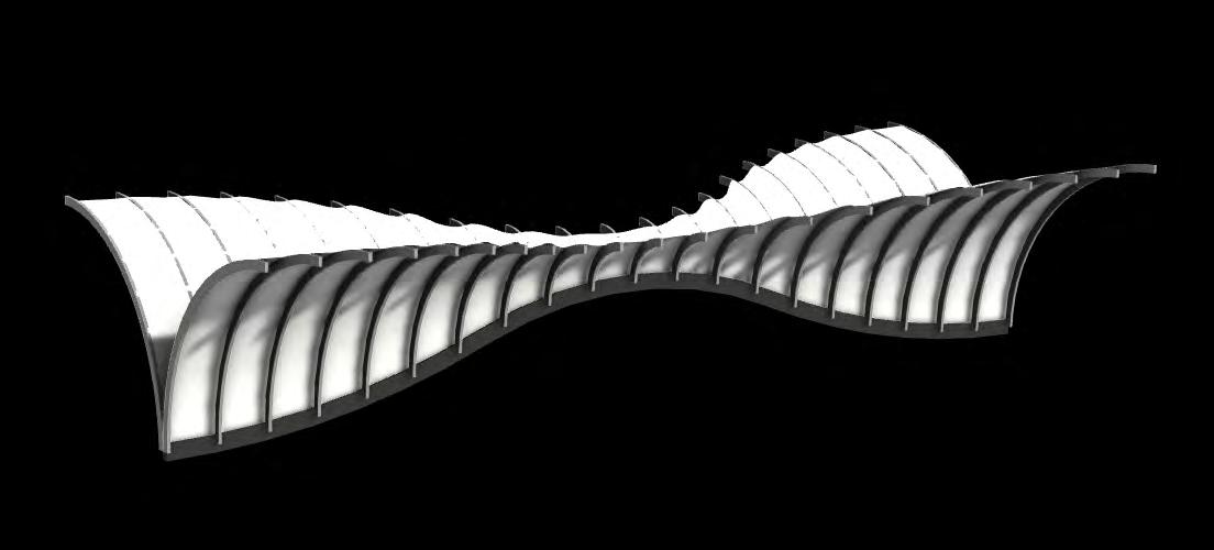
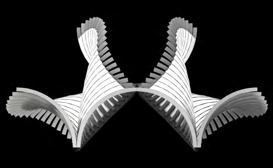
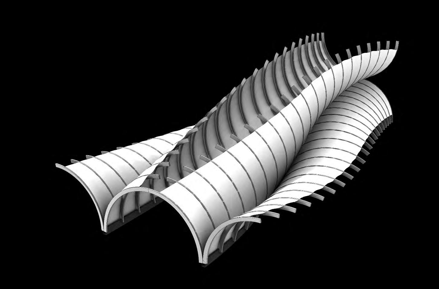
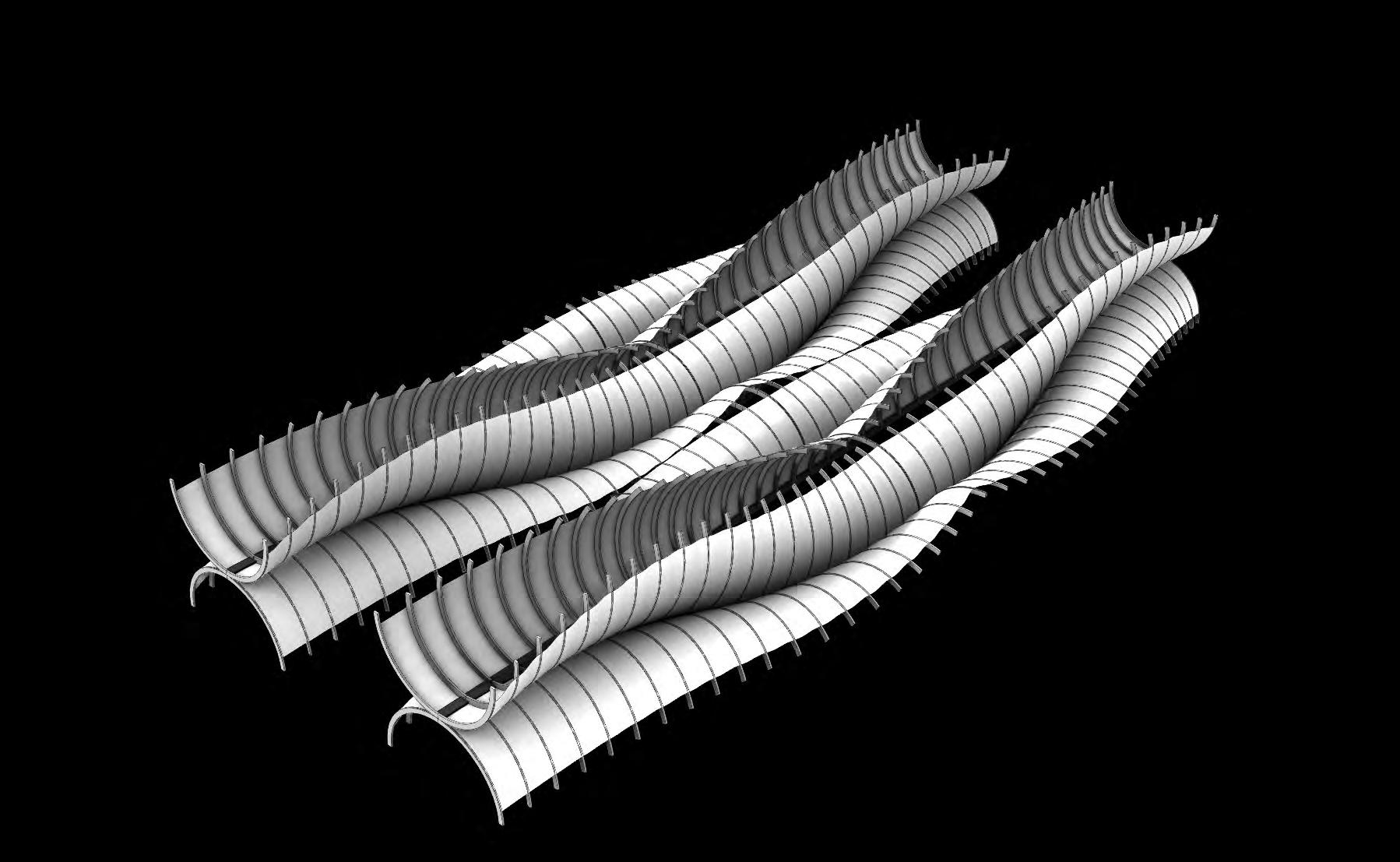
The spine twists 90° along its length. The arches stay regular. The module can be mirrored and expanded to create a weaved membrane.
Single module front view
Mirrored modules front view
Single module side view
Mirrored modules perspective view
Expanded modules perspective view
Site - pHYSICAL mODEL
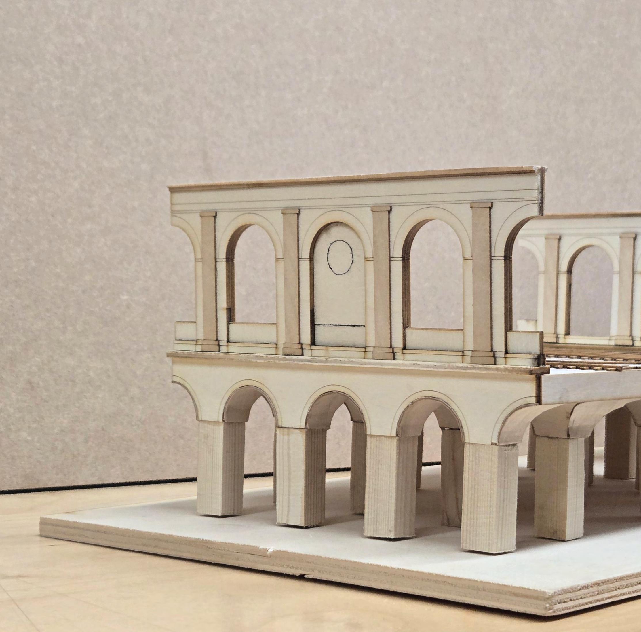
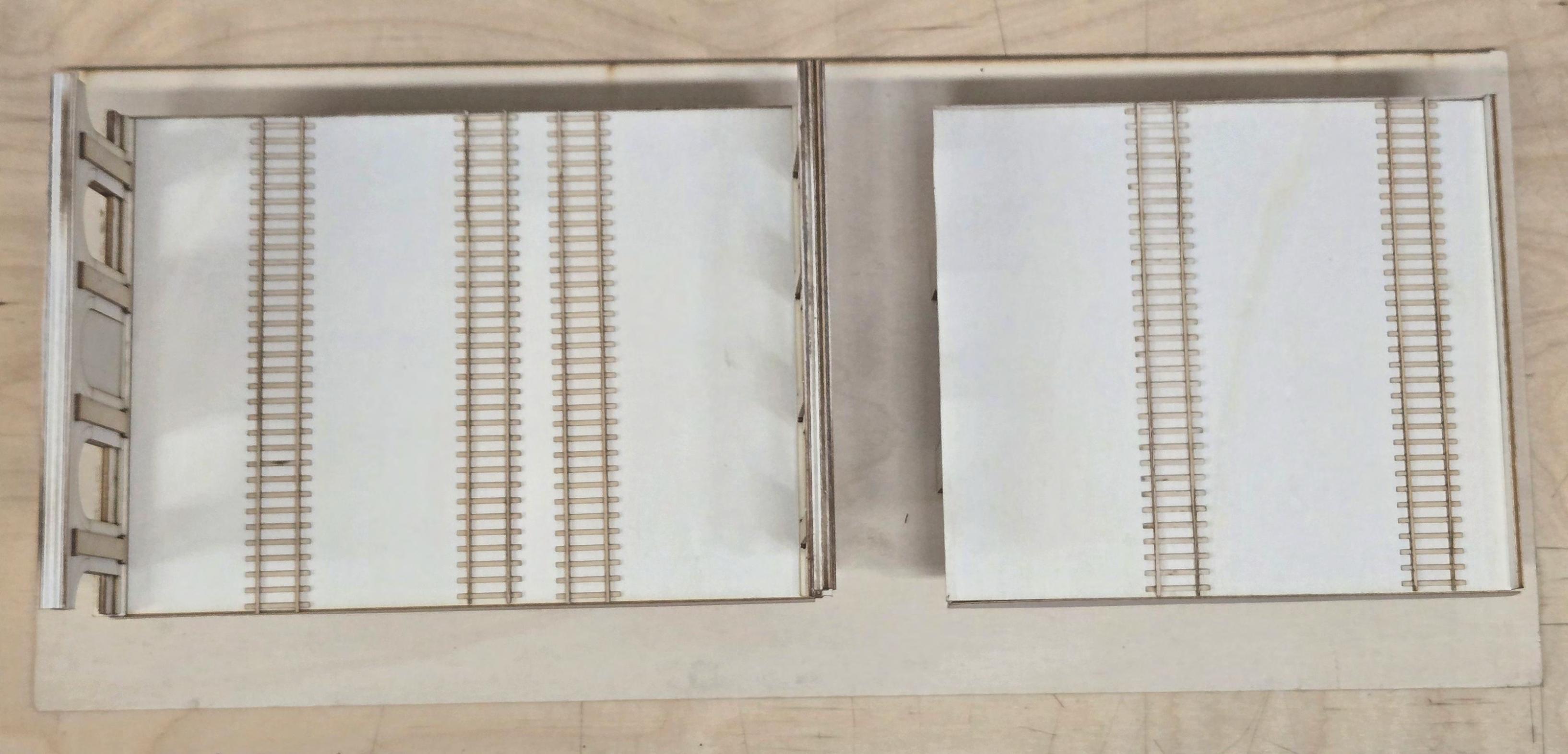
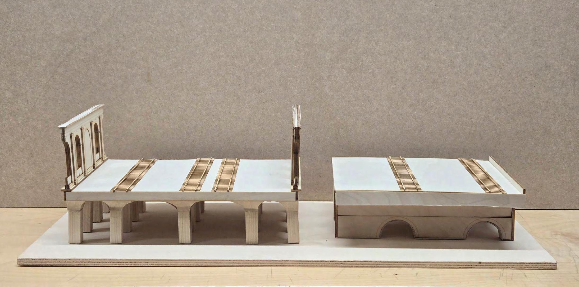
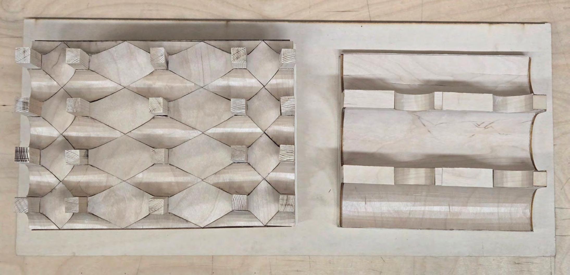
A slice of the existing station was modeled to gain an understanding of the site and the challenges of introducing a new intervention within.
Fragment - Footbridge Iteration
The footbridge leads pedestrians above the façade while leaping above the road. Its slender and transparent silhouette aim to avoid taking the focus away from the façade. But the complexity of the structure fails this goal.
The arched structure minimises the overshadowing of the façade.
The structure aims to expand as the roof of the station. It is however quite dominant over the original building.
Perspective View
Section
The roof wraps and folds to create openings and channel the pedestrians up.
Concept - Early Massing
Concept - Early Massing
All work produced by Unit 14 Unit book design by Charlie Harriswww.bartlett.ucl.ac.uk/architecture
Copyright 2021 The Bartlett School of Architecture, UCL All rights reserved.
No part of this publication may be reproduced or transmited in any form or by any means, electronic or mechanical, including photocopy, recording or any information storage and retreival system without permission in writing from the publisher.
At the center of Unit 14’s academic exploration lies Buckminster Fuller’s ideal of the ‘The Comprehensive Designer’, a master-builder that follows Renaissance principles and a holistic approach. Fuller referred to this ideal of the designer as somebody who is capable of comprehending the ‘integrateable significance’ of specialised findings and is able to realise and coordinate the commonwealth potentials of these discoveries while not disappearing into a career of expertise. Like Fuller, we are opportunists in search of new ideas and their benefits via architectural synthesis. As such Unit 14 is a test bed for exploration and innovation, examining the role of the architect in an environment of continuous change. We are in search of the new, leveraging technologies, workflows and modes of production seen in disciplines outside our own. We test ideas systematically by means of digital as well as physical drawings, models and prototypes. Our work evolves around technological speculation with a research-driven core, generating momentum through astute synthesis. Our propositions are ultimately made through the design of buildings and through the in-depth consideration of structural formation and tectonic. This, coupled with a strong research ethos, will generate new and unprecedented, one day viable and spectacular proposals. They will be beautiful because of their intelligence - extraordinary findings and the artful integration of those into architecture.
The focus of this year’s work evolves around the concept of ‘Constructed Futures’. The term aims to describe architecture and as such fundamentally human future as the result of the architect’s highest degree of synthesis of underlying principles. Constructional logic, spatial innovation, typological organisation, environmental and structural performance are all negotiated in a highly iterative process driven by intense architectural investigation. Inspiration for inherent principles of organisational intelligence can be observed in both biotic and abiotic systems, in all spatial arrangements where it is critical for the overall performance of the developed order. Through the deep understanding of constructional principles, we will generate highly developed architectural systems of unencountered intensity where spatial organisation arises as a result of sets of mutual interactions. Observation as well as re-examination of civilisatory developments will enable us to project near future scenarios and position ourselves as avant-garde in the process of designing a comprehensive vision for the forthcoming. The projects will take shape as research based imaginative tales, architectural visions driven by speculation.
Thanks to: Seth Stein Architects, DKFS, ZHA, Foster and Partners, Minifie Architects, Buro Happold, Amanda Levete Architects, Penta Real Estate, RSHP