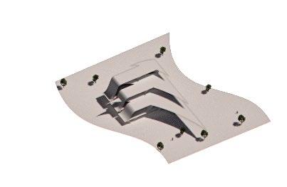
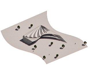
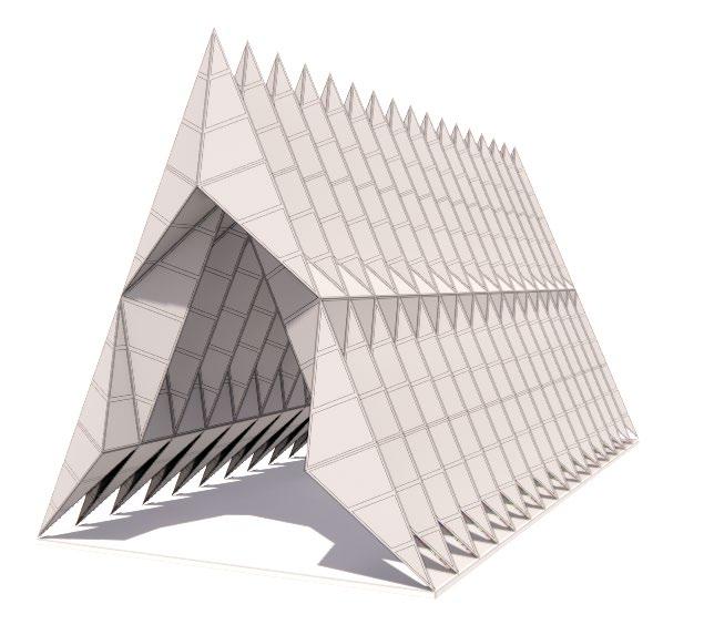
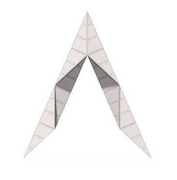
Daniel Febvre_Y4 | Unit 14 | Bartlett School of Architecture
DANIEL FEBVREYEAR 4
All work produced by Unit 14
Cover design by Charlie Harris
www.bartlett.ucl.ac.uk/architecture
Copyright 2021
The Bartlett School of Architecture, UCL All rights reserved.
No part of this publication may be reproduced or transmitted in any form or by any means, electronic or mechanical, including photocopy, recording or any information storage and retrieval system without permission in writing from the publisher.
@unit14_ucl
daniel.febvre1@gmail.com
BETWEEN CRAFT & CROSSING
SHOREHAM PORT FERRY TERMINAL
Sussex, UK
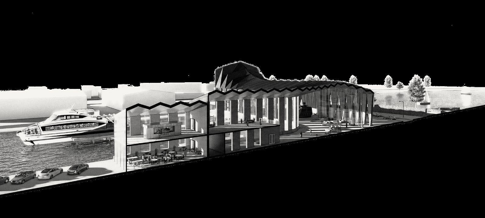
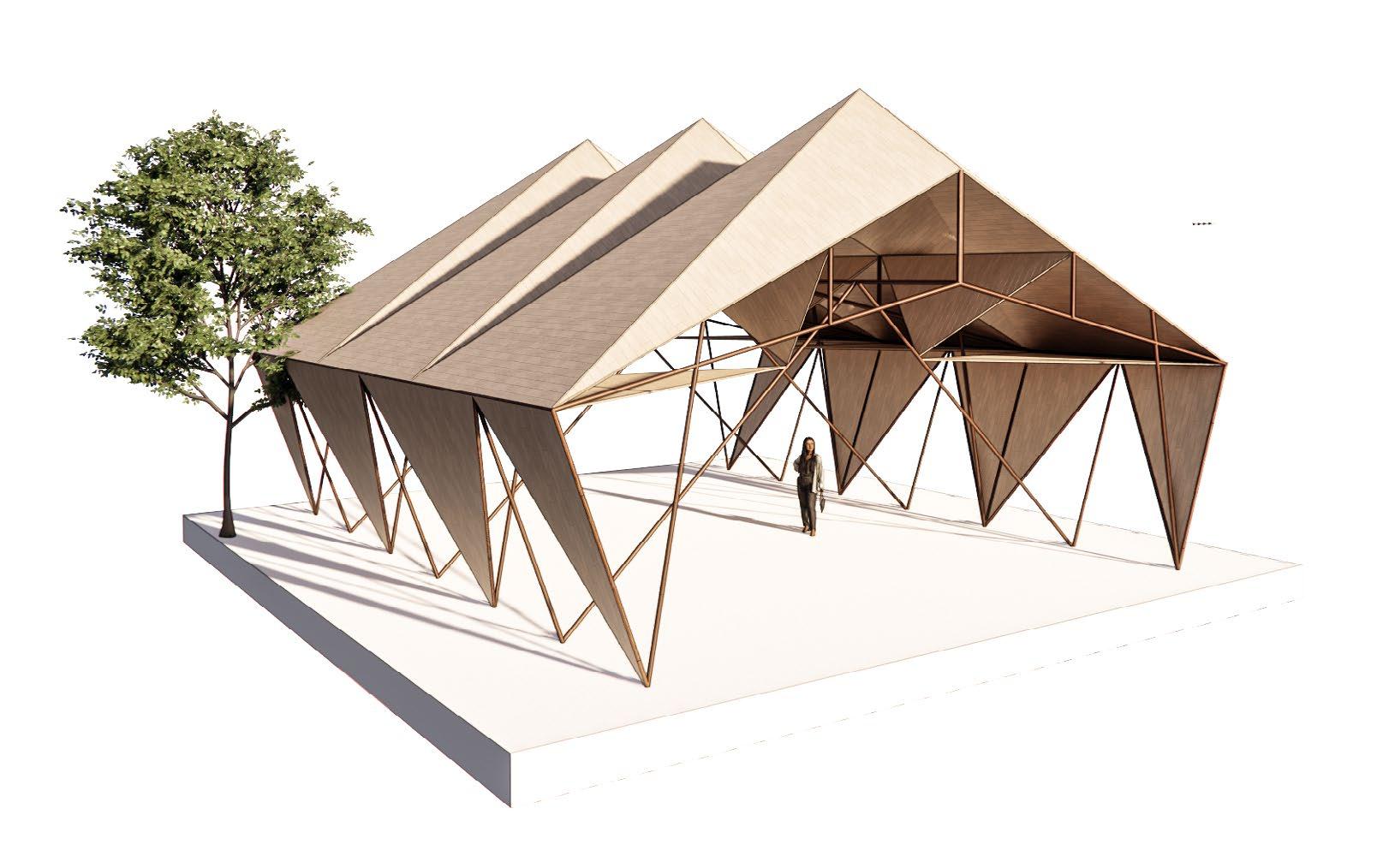
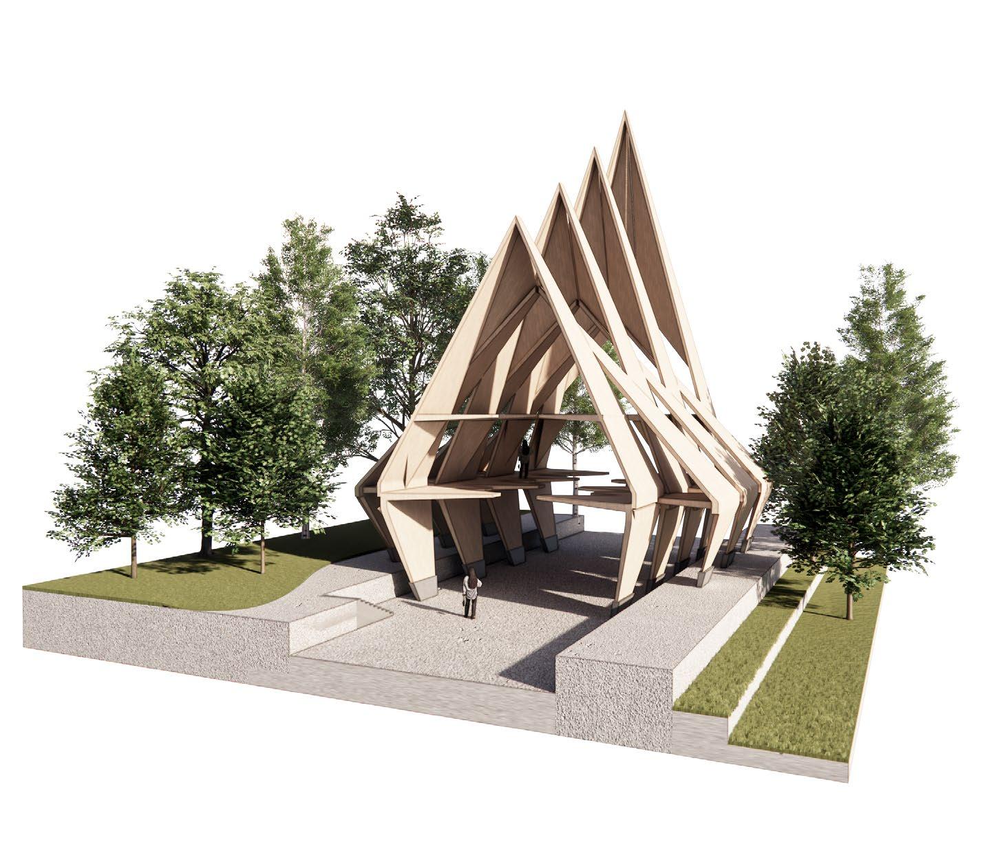
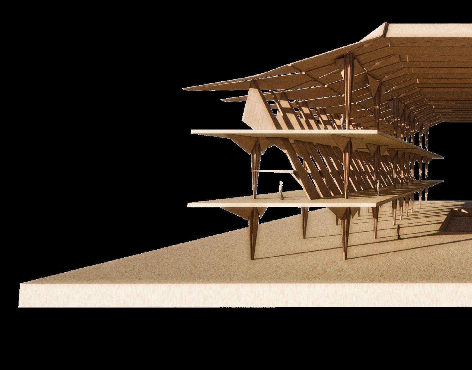
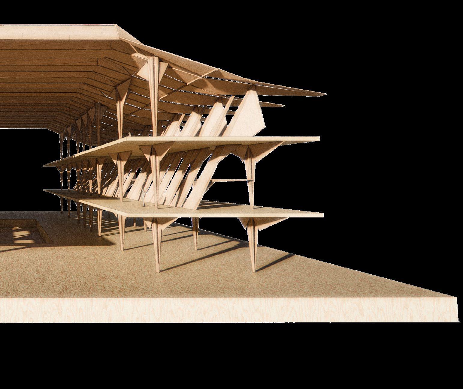
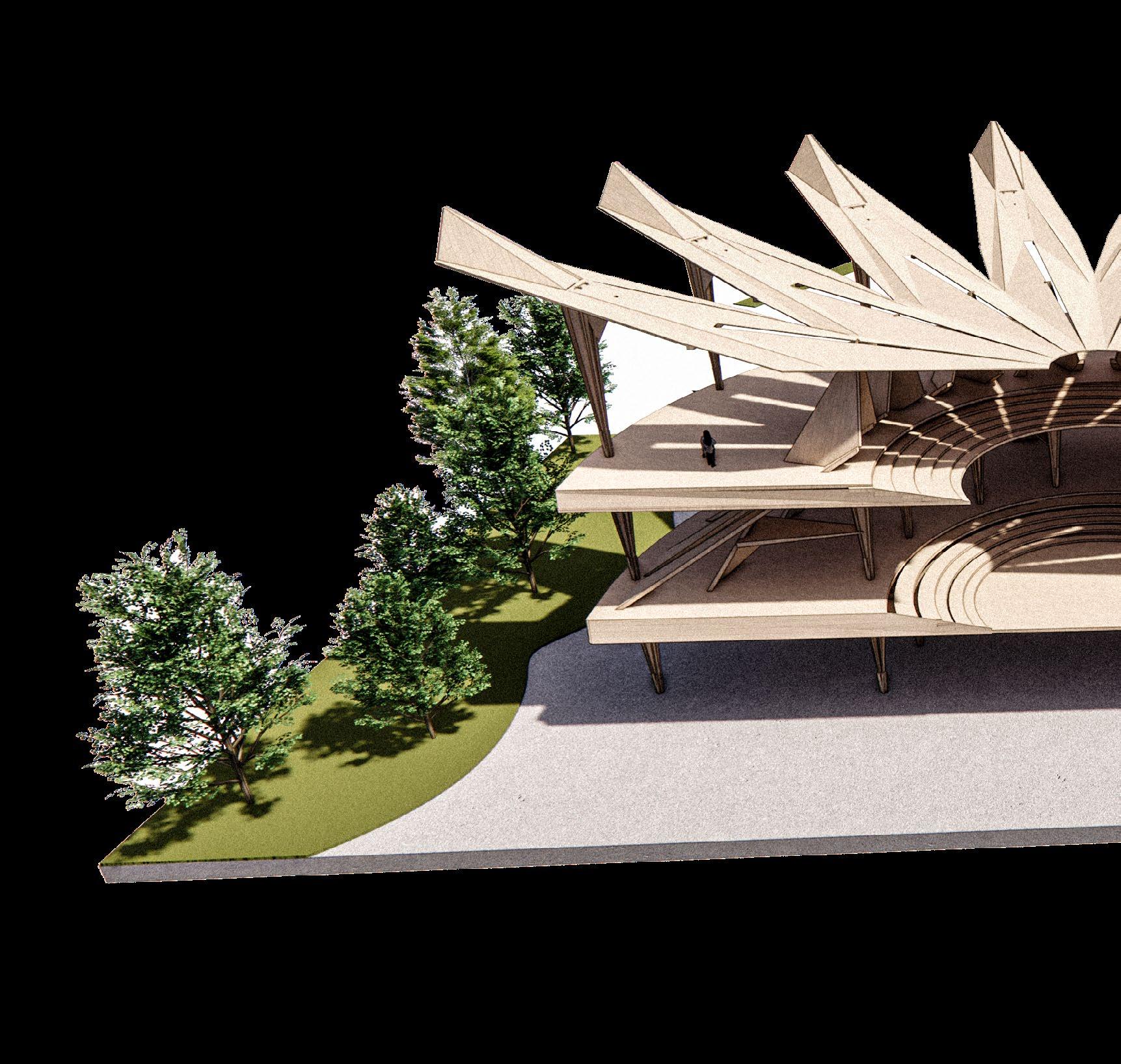
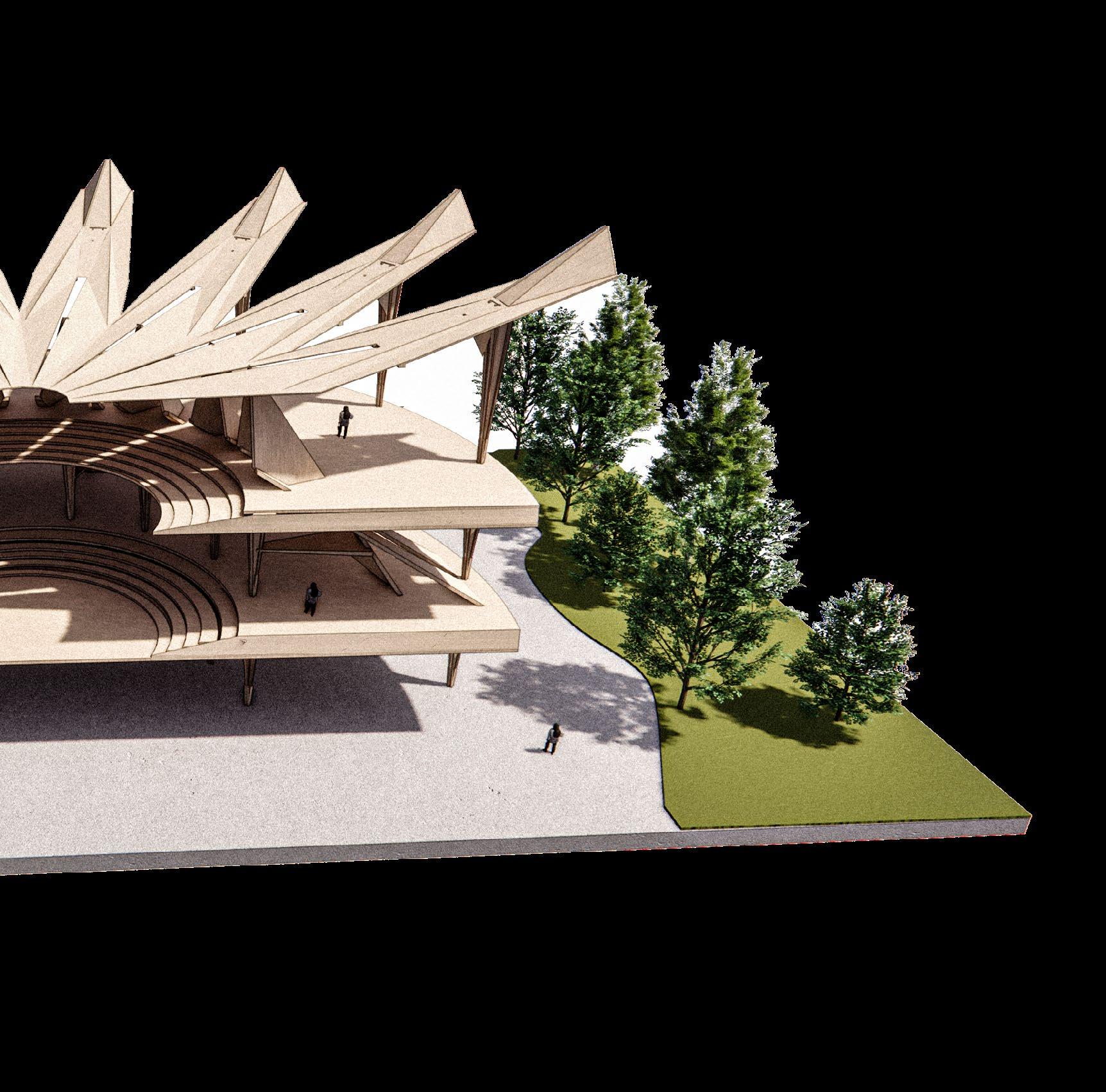
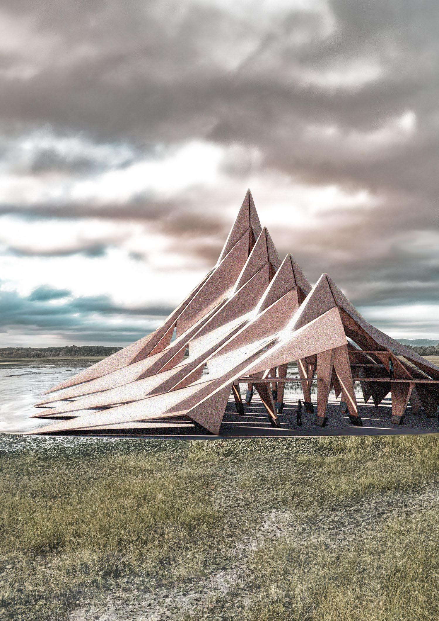
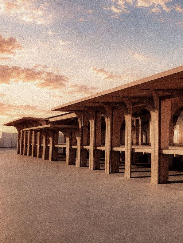
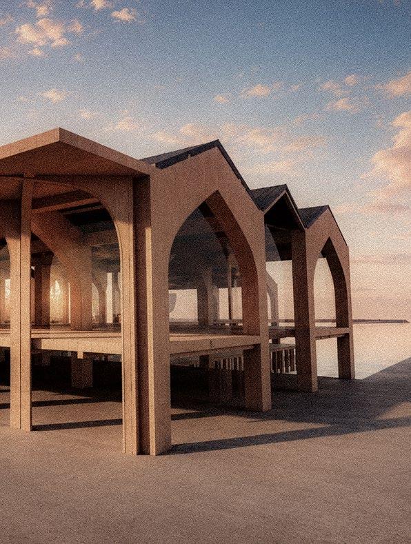
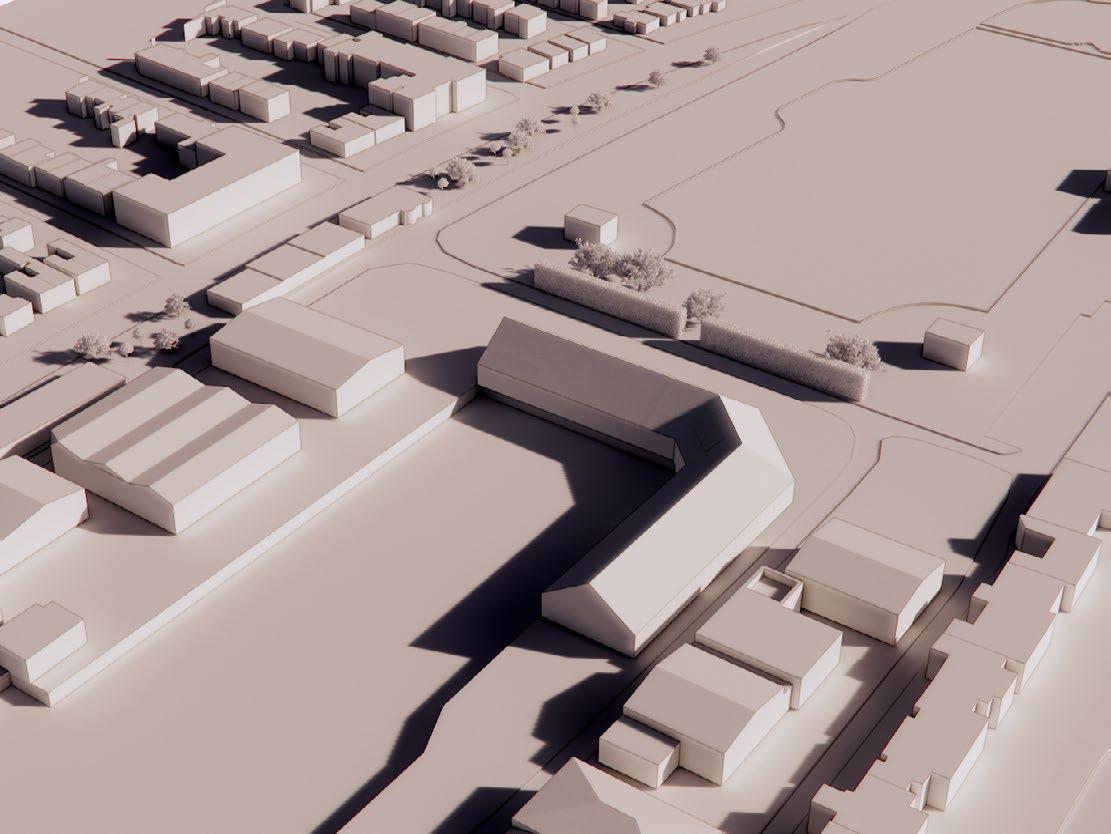
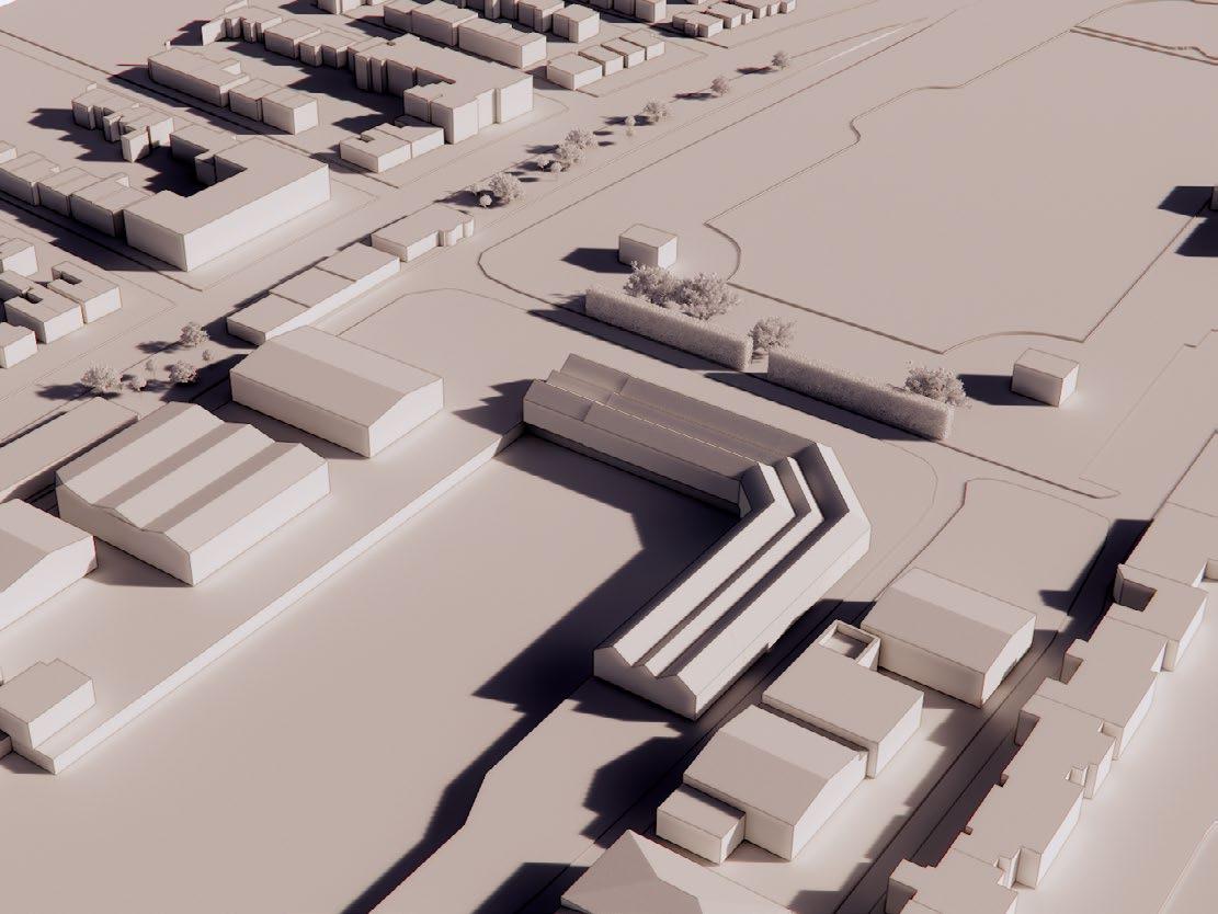
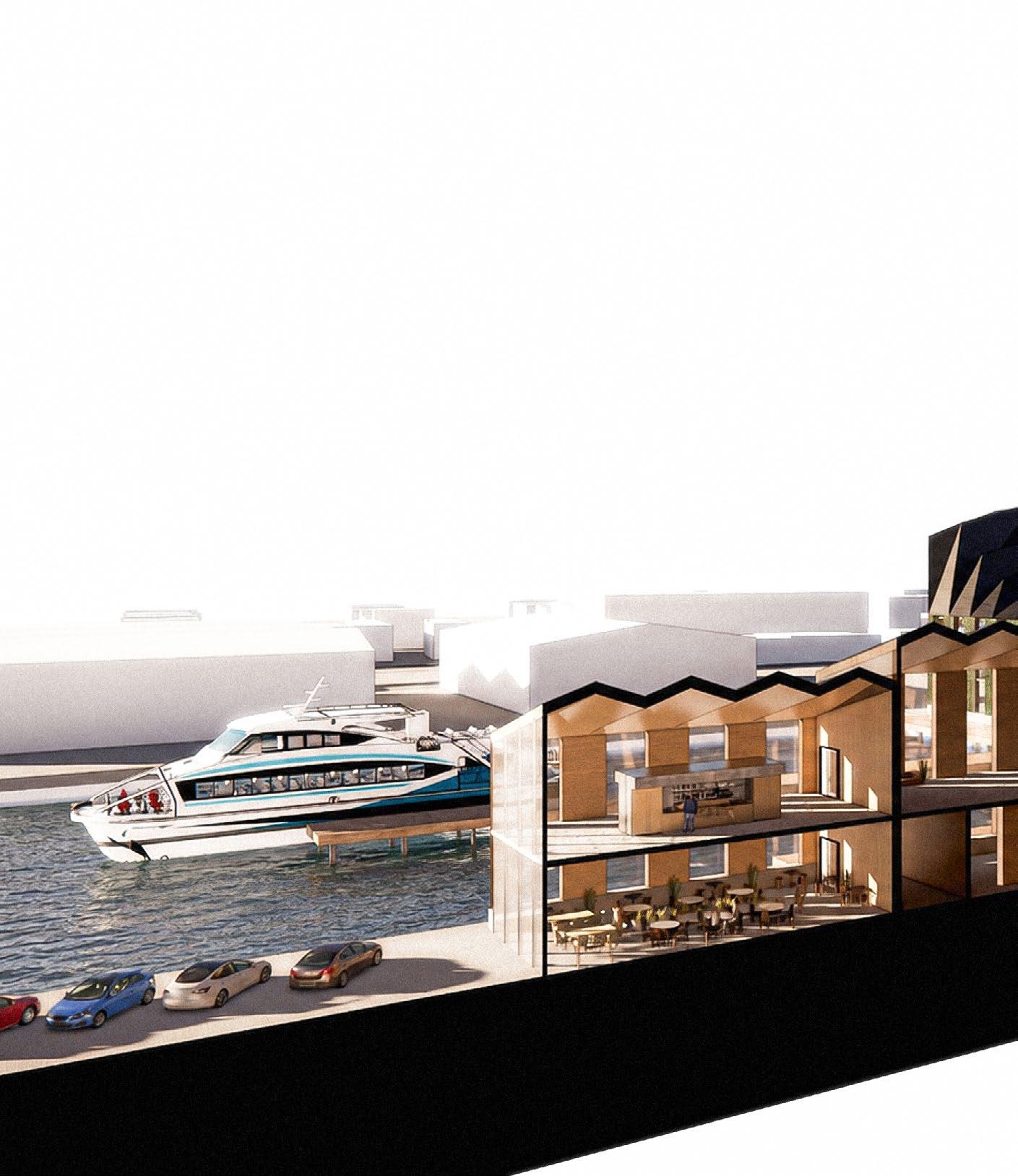
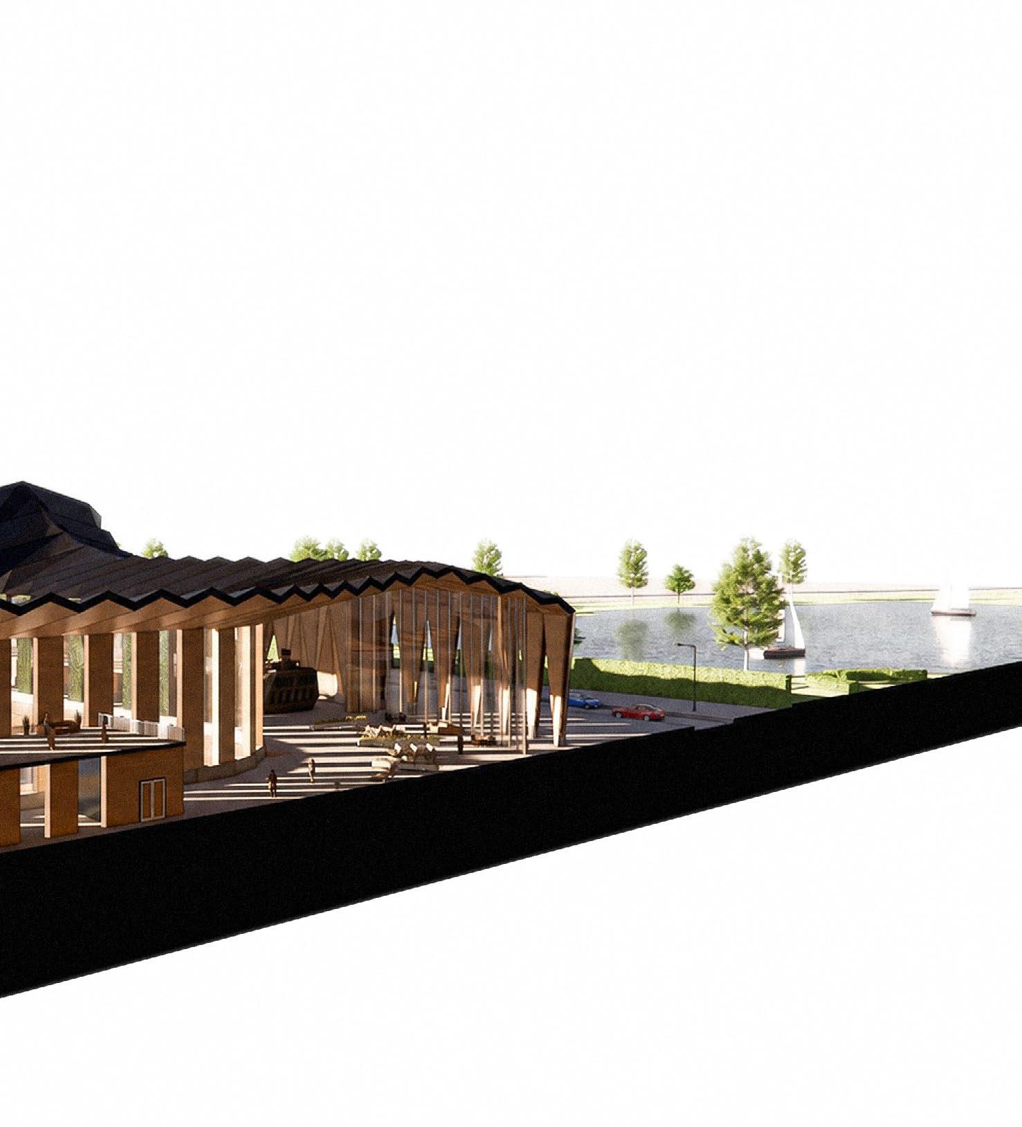
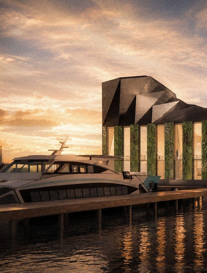
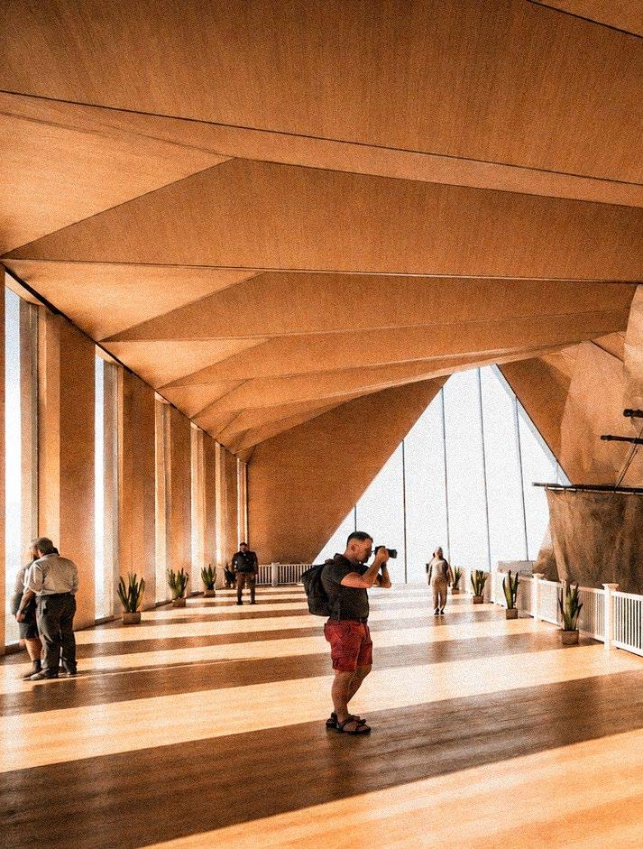
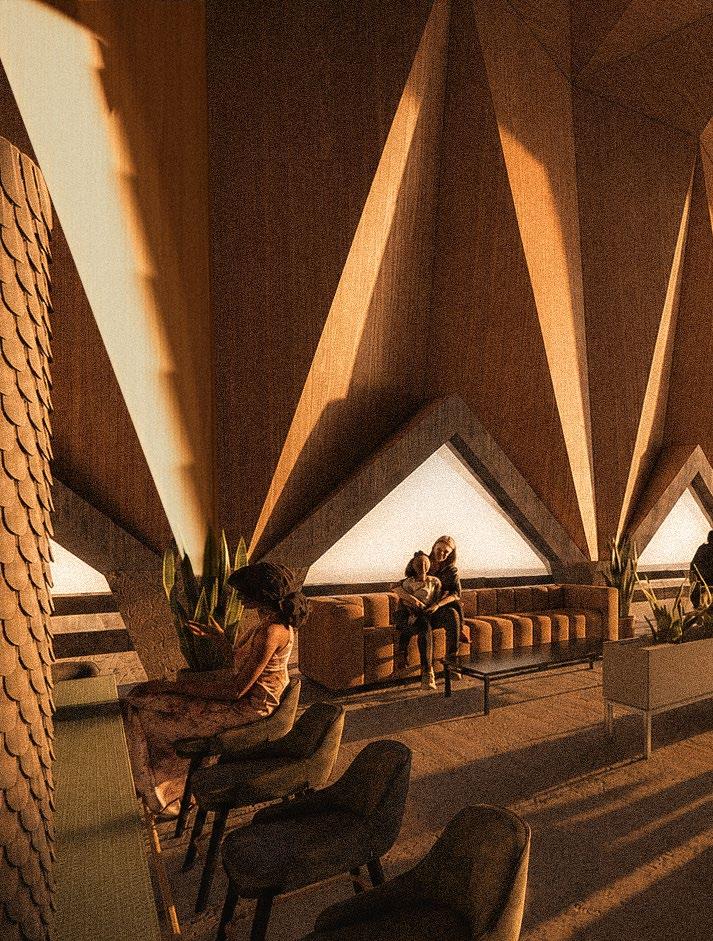
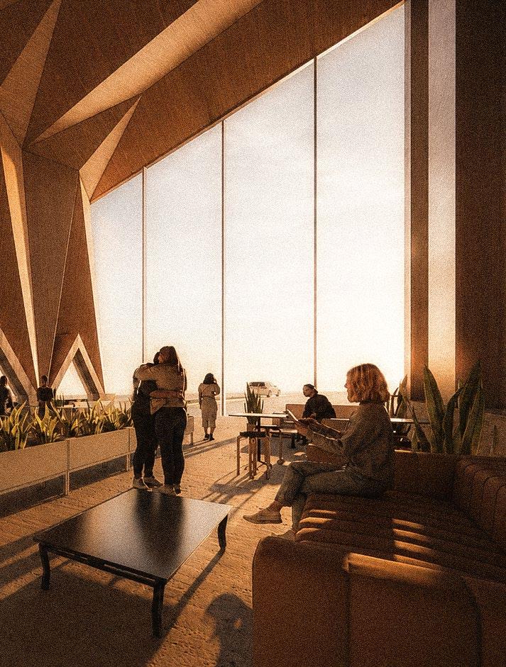
The project proposes a regional ferry terminal, maritime museum and timber boat construction facility at Shoreham Port, reimagining the harbour as a strategic node within a decentralised South Coast maritime network. Positioned between Portsmouth and Dover, Shoreham ha the potential to support growing passenger, freight and coastal transport services while relieving pressure on larger ports. Responding to ambitions outlined in the Shoreham Harbour Joint Area Action Plan, the scheme explores how smaller ports can play a greater role in future transport infrastructure while reconnecting industrial waterfronts with public use.
The design emerged through research into folded structural systems and timber construction. Studies of precedents, including the United States Air Force Cadet Chapel and Gare de
Mons, alongside industrial sheds and maritime infrastructure, informed the development of a folded architectural language.
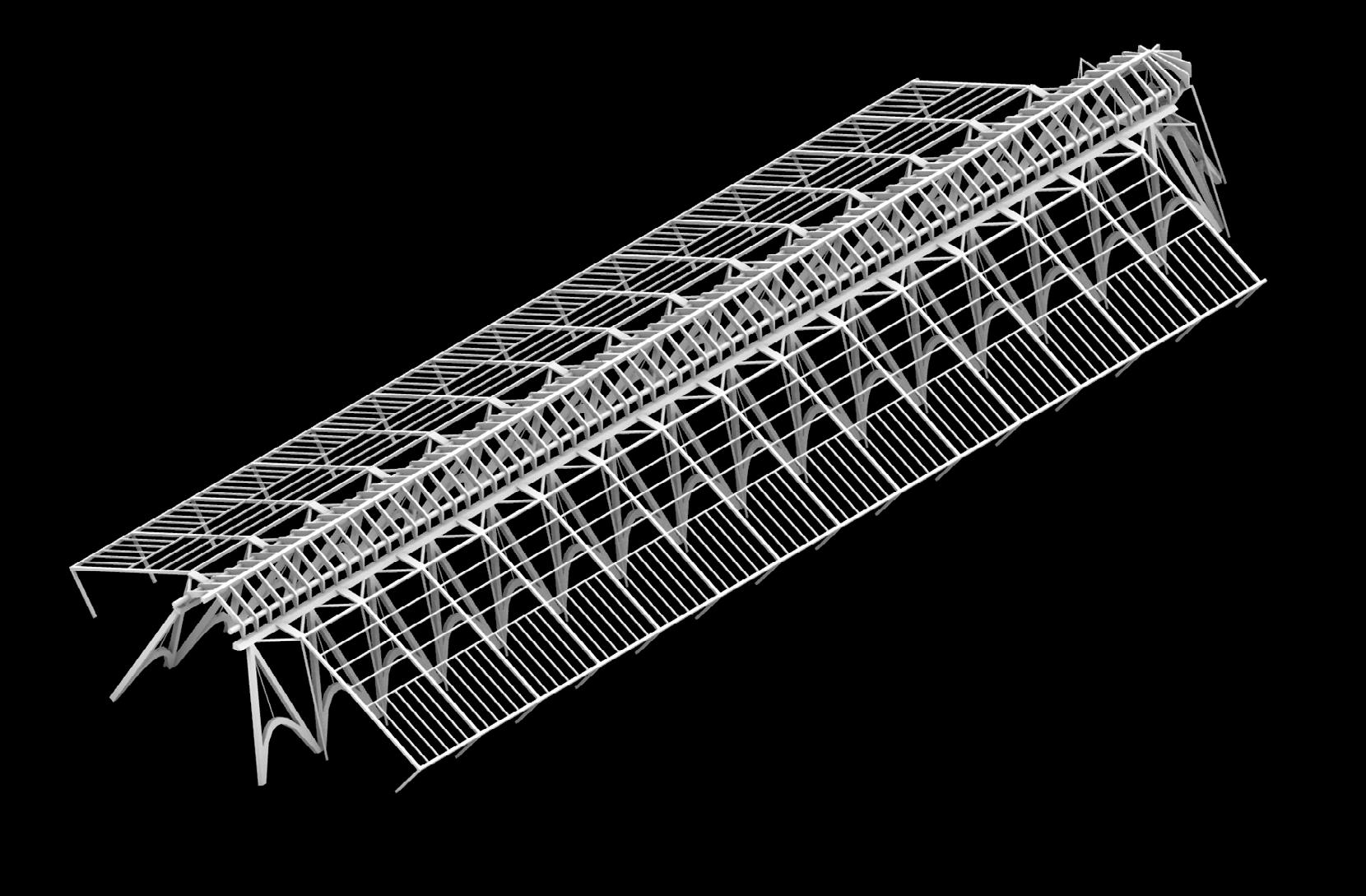
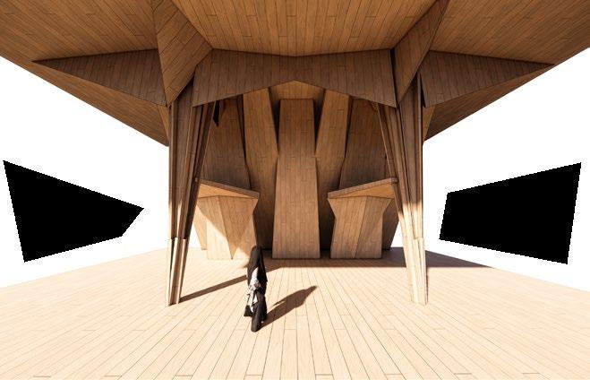
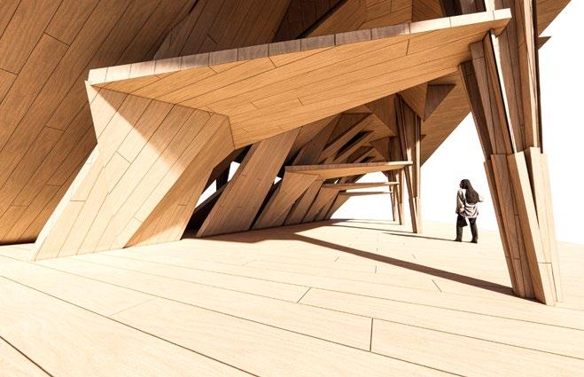
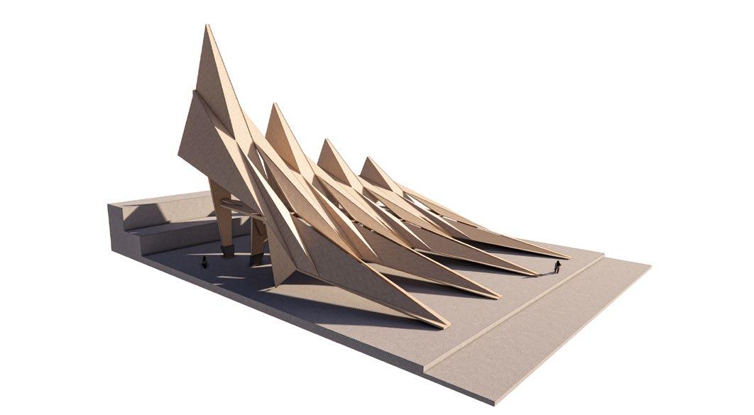
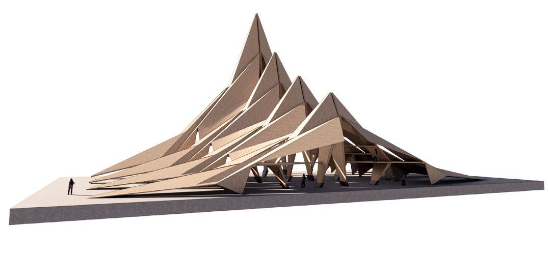
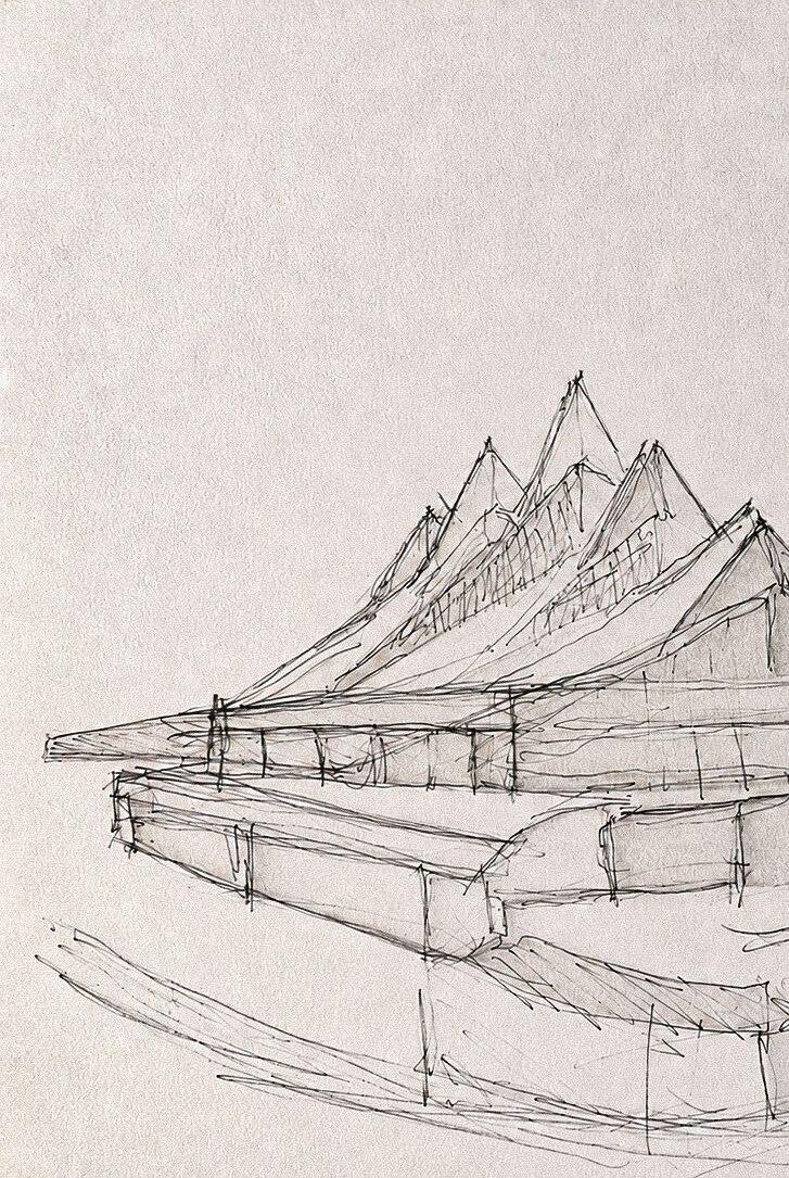
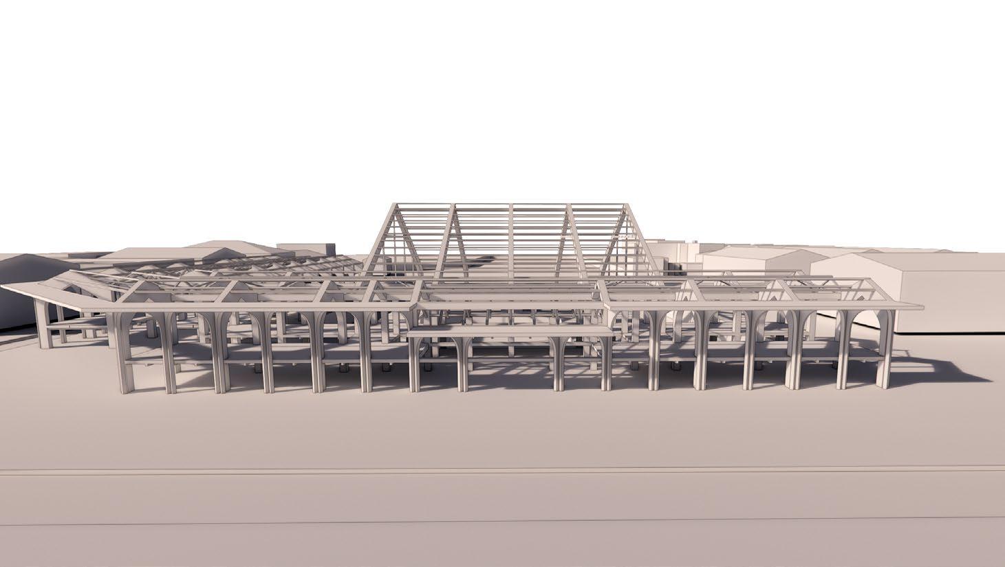
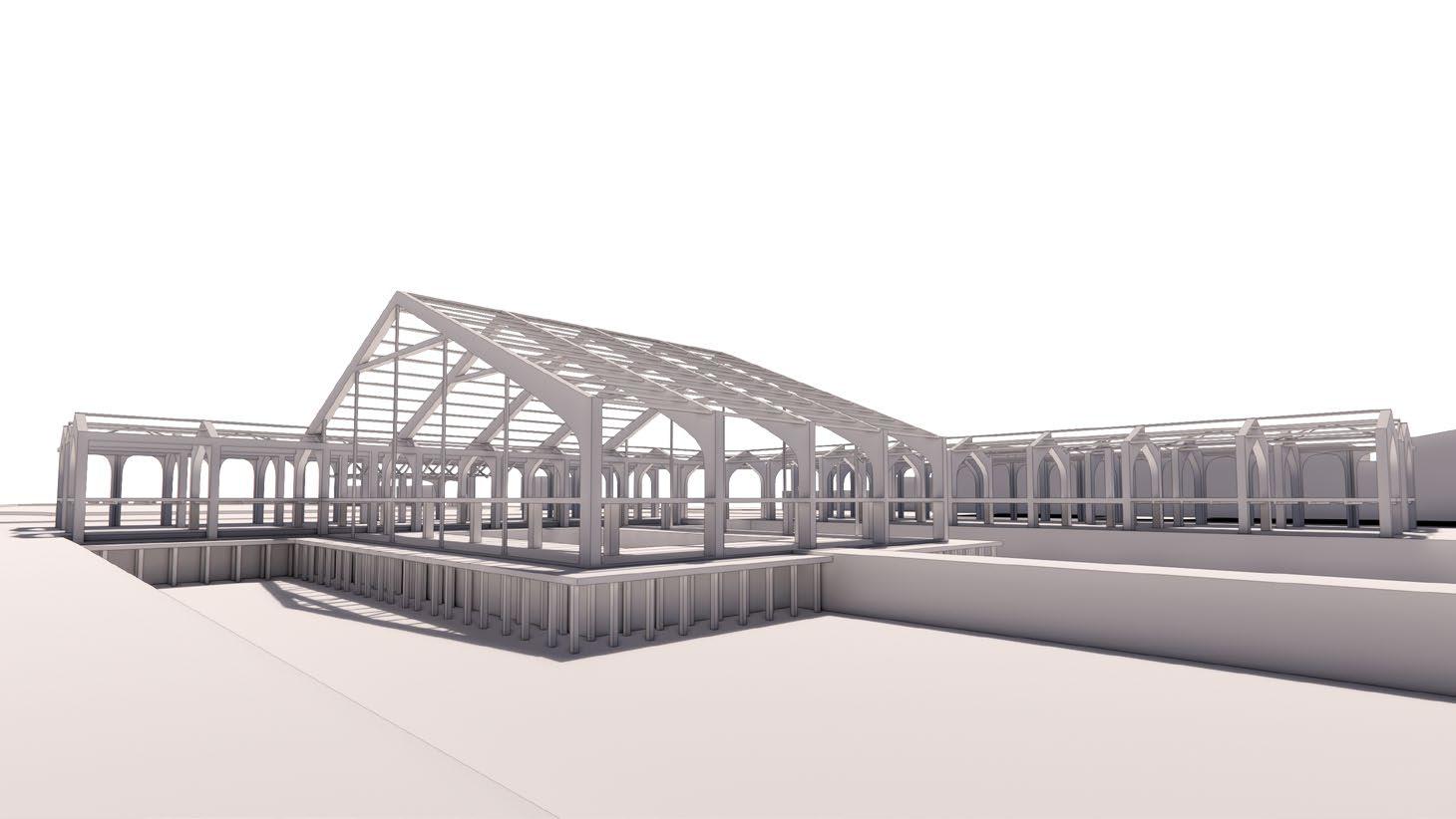
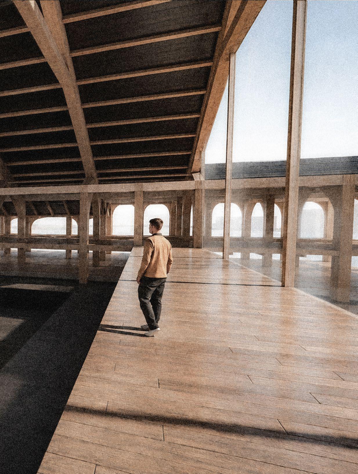
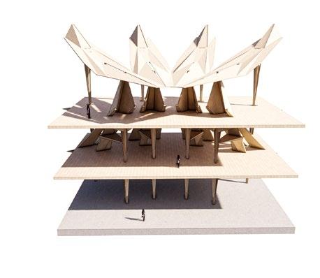
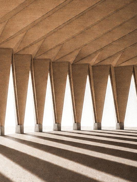
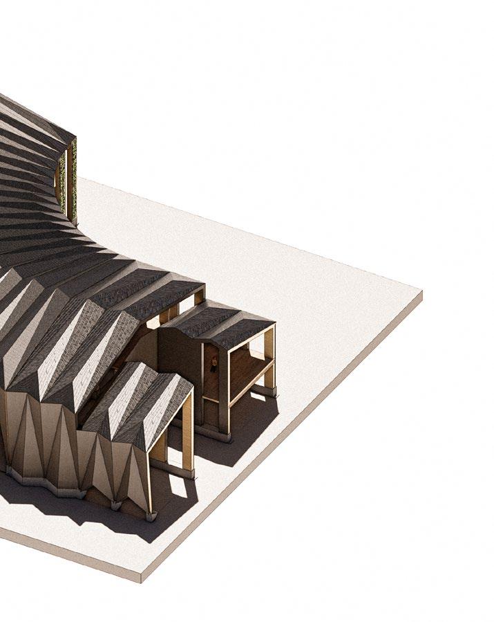
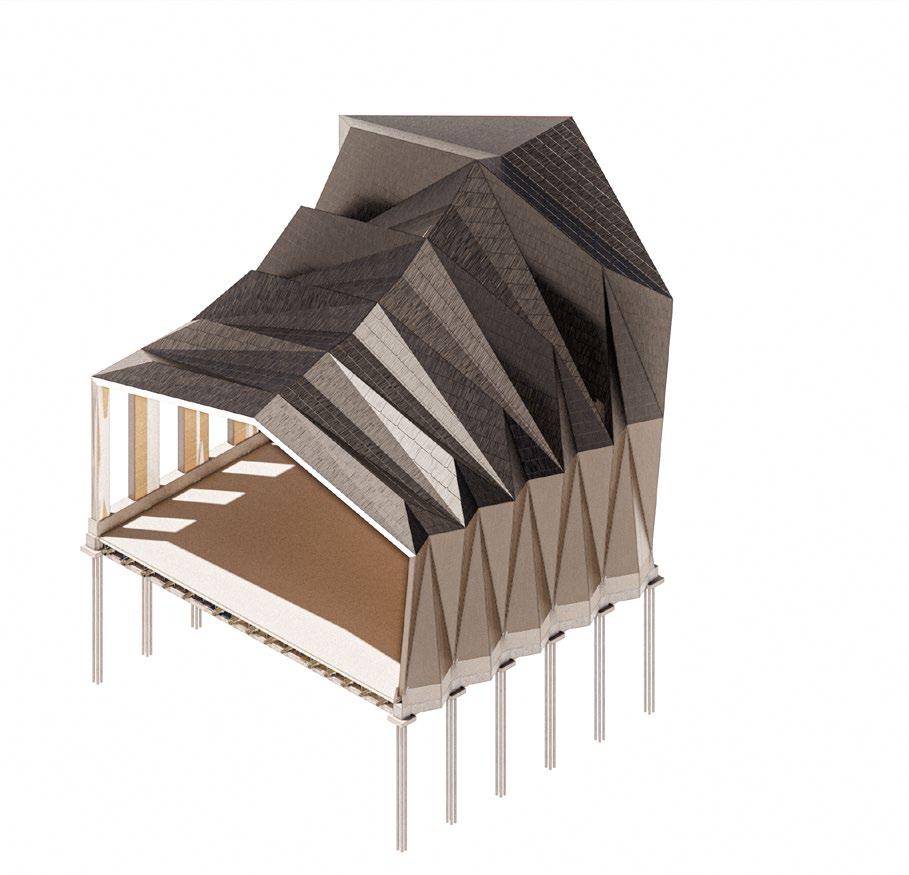
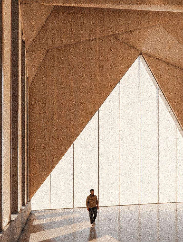
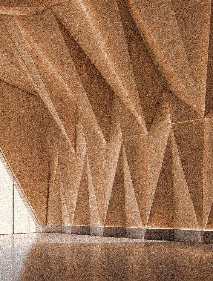
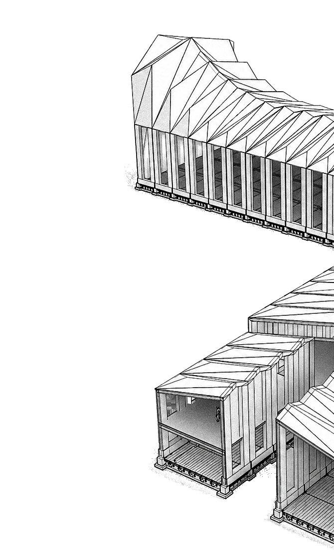
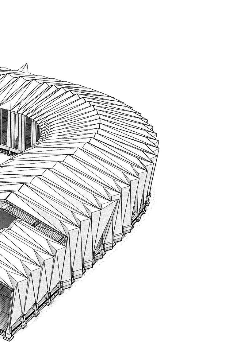
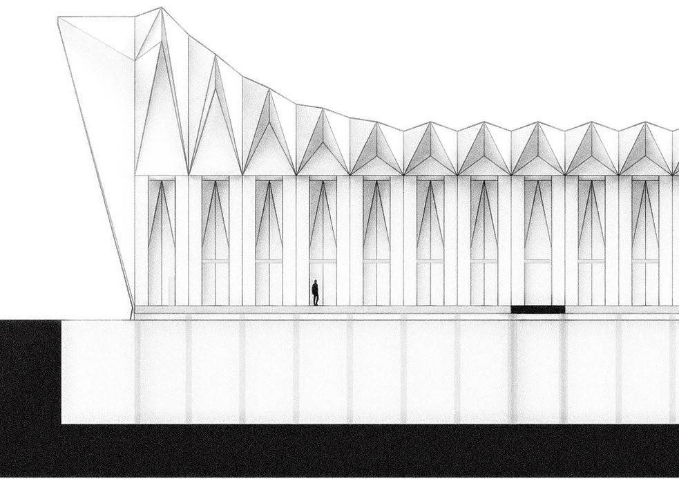
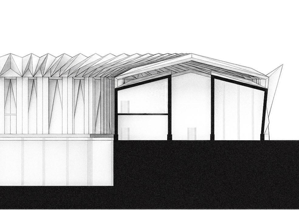
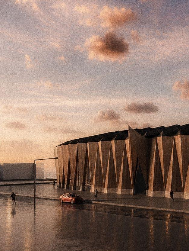
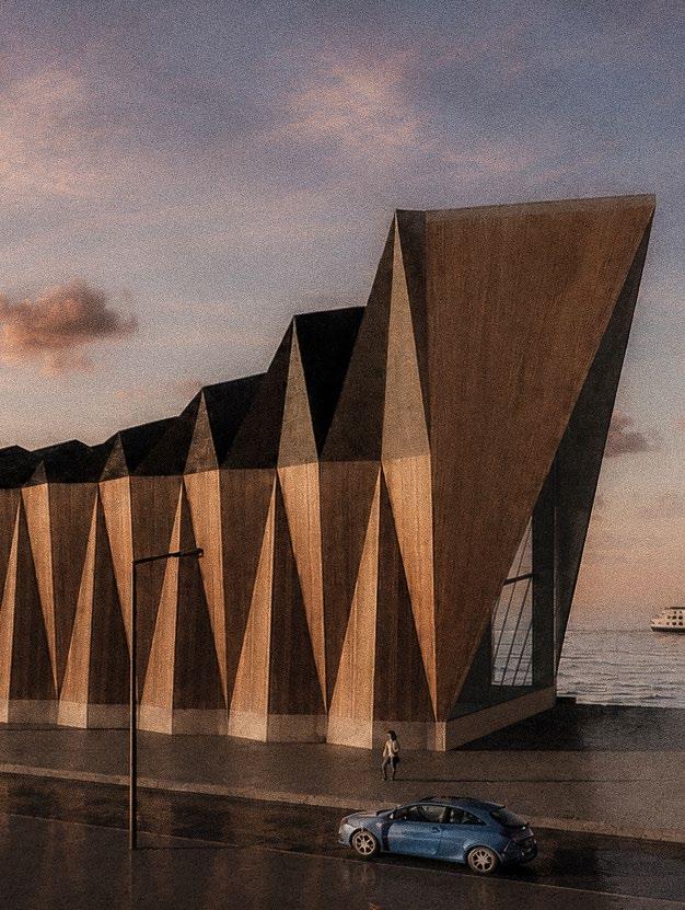
The scheme combines ferry operations, boat restoration and culture, showcasing generations of boat usage, within a prefabricated folded CLT structure to create hierarchy, directing movement and enabling large-span spaces through a unified timber system.
SECTION 1
TECTONIC INVESTIGATION
TECTONIC PRECEDENT STUDY
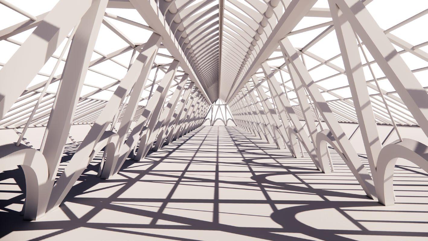
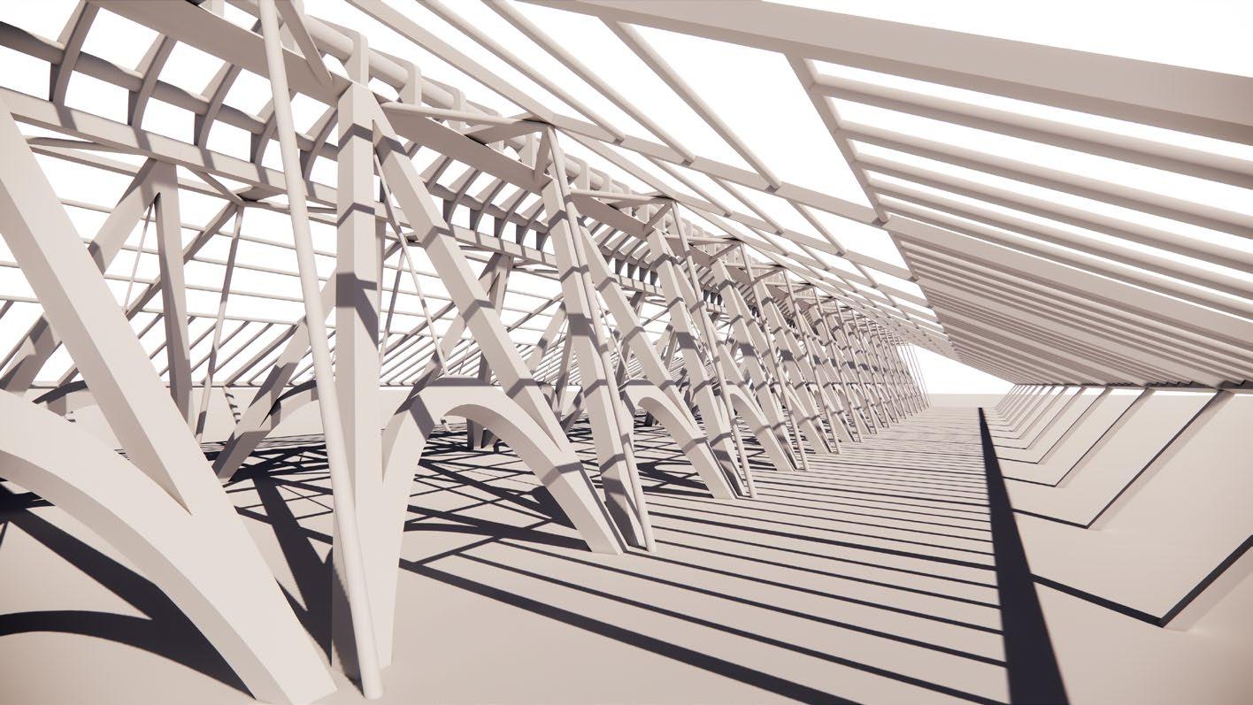
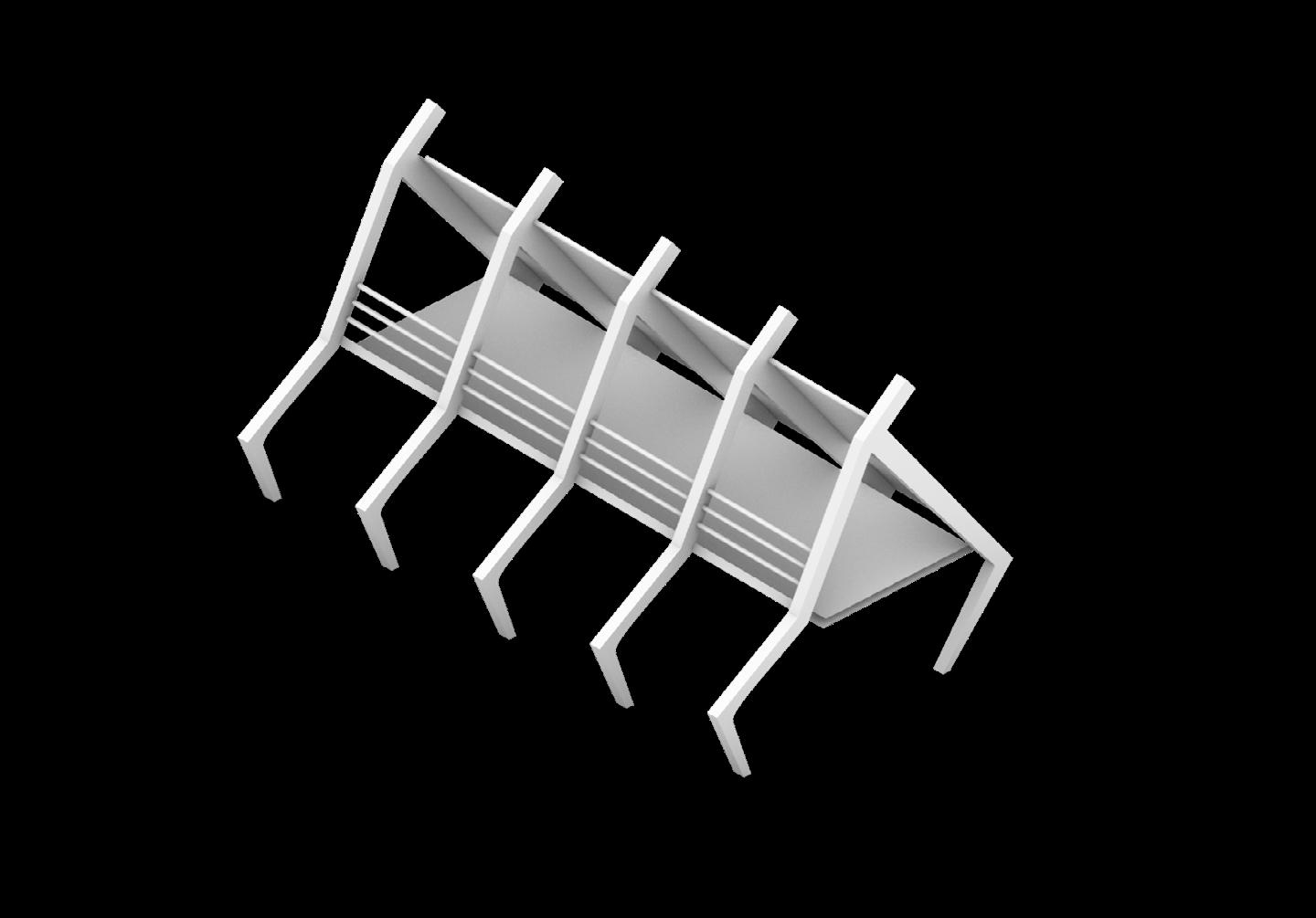
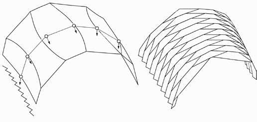
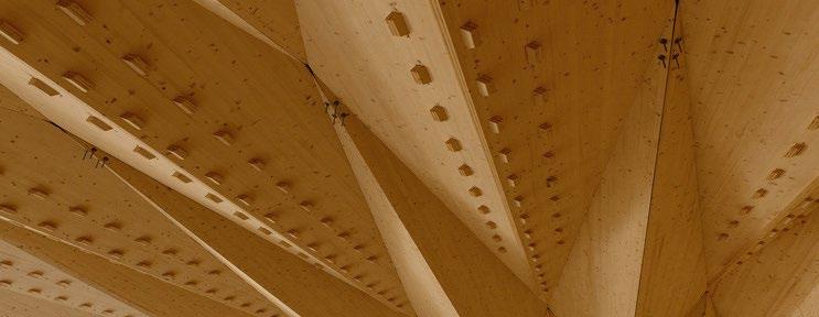
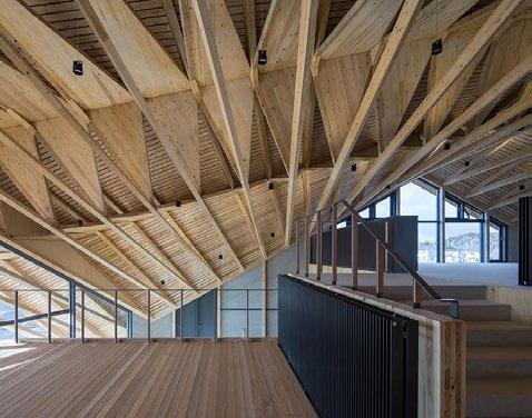
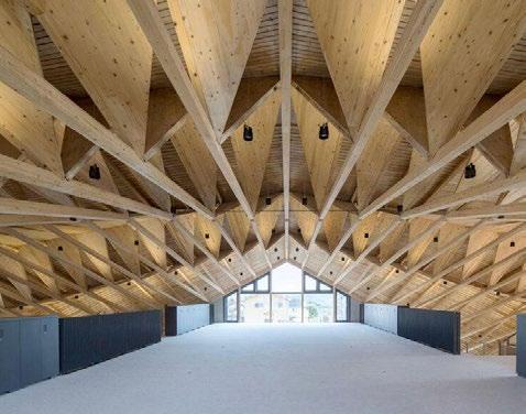
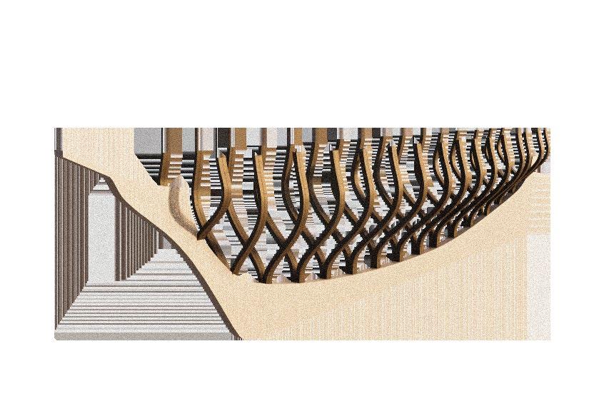
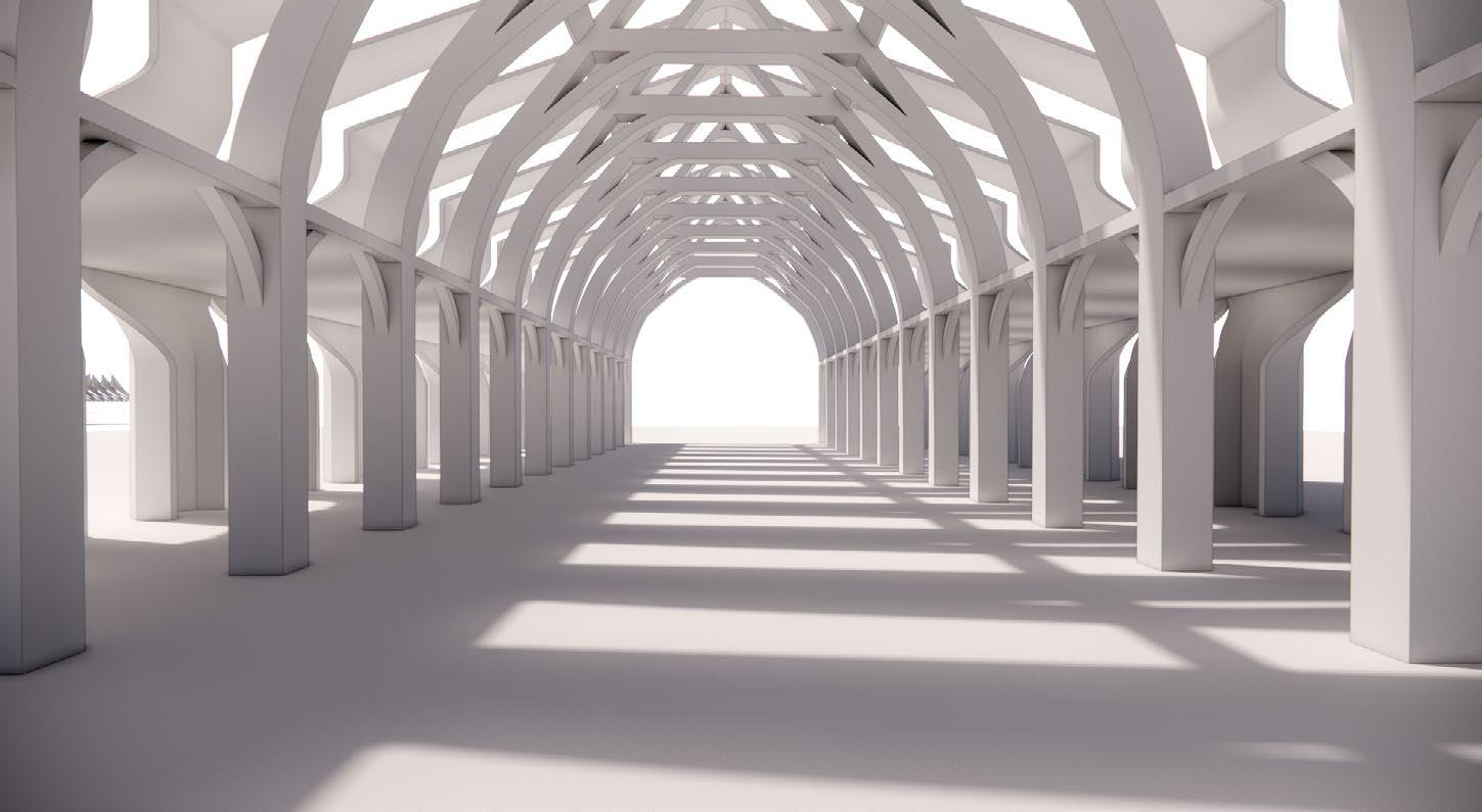
Gare De Mons employs a repetitive rib structure that operates simultaneously as enclosure and loadbearing system. Inclined members distribute forces laterally while establishing a continuous spatial rhythm.
SURFACE ABSTRACTION
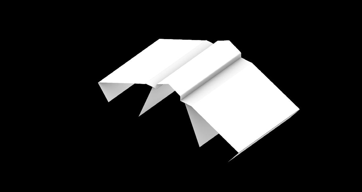
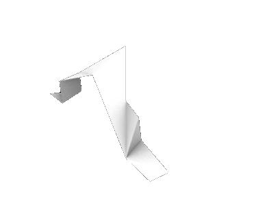
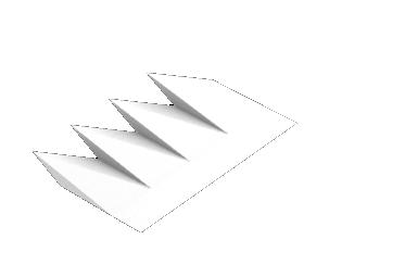
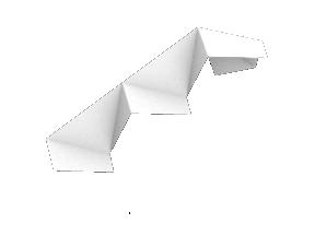
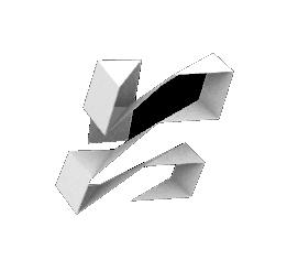
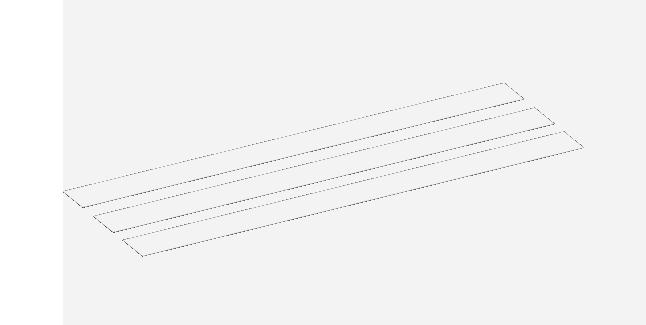
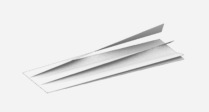
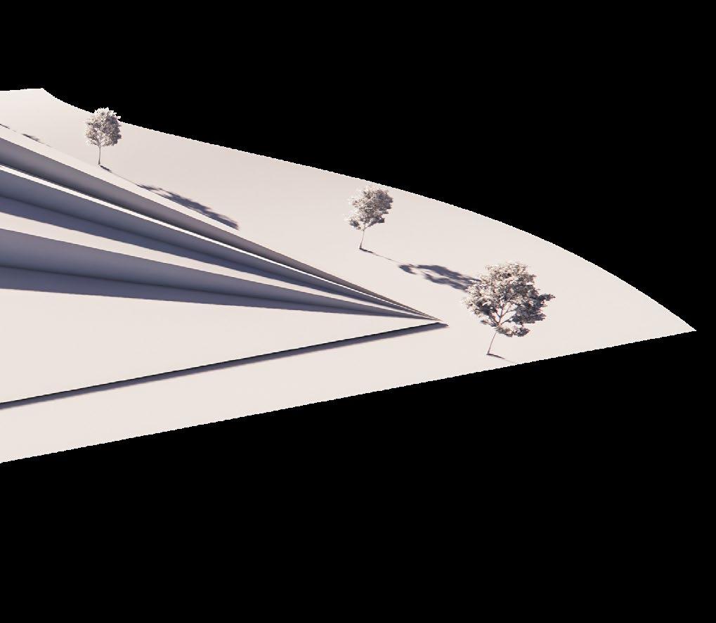
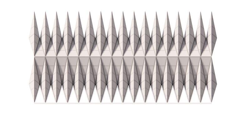
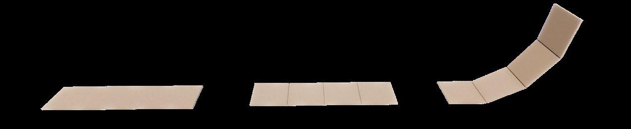
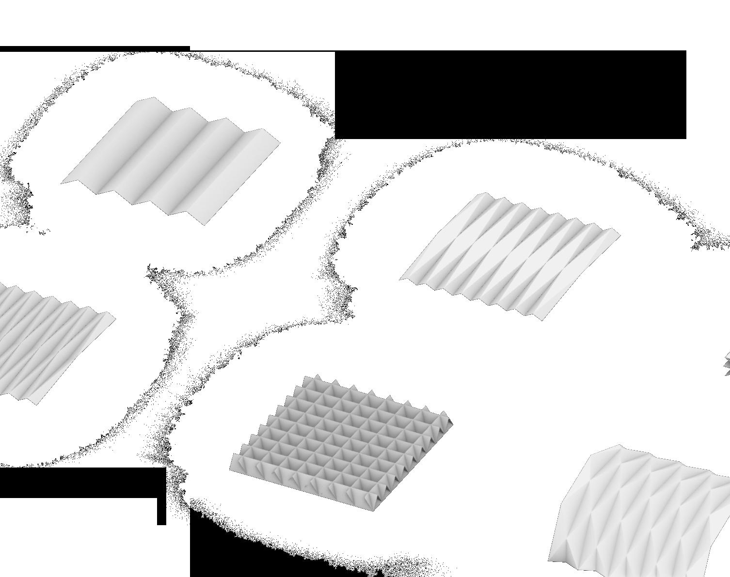
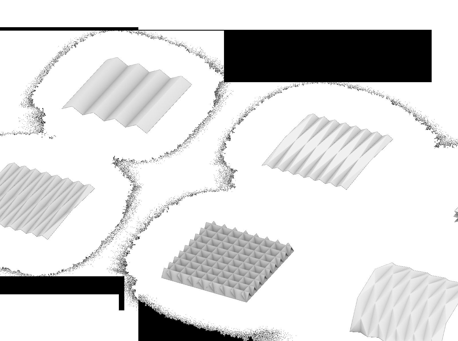
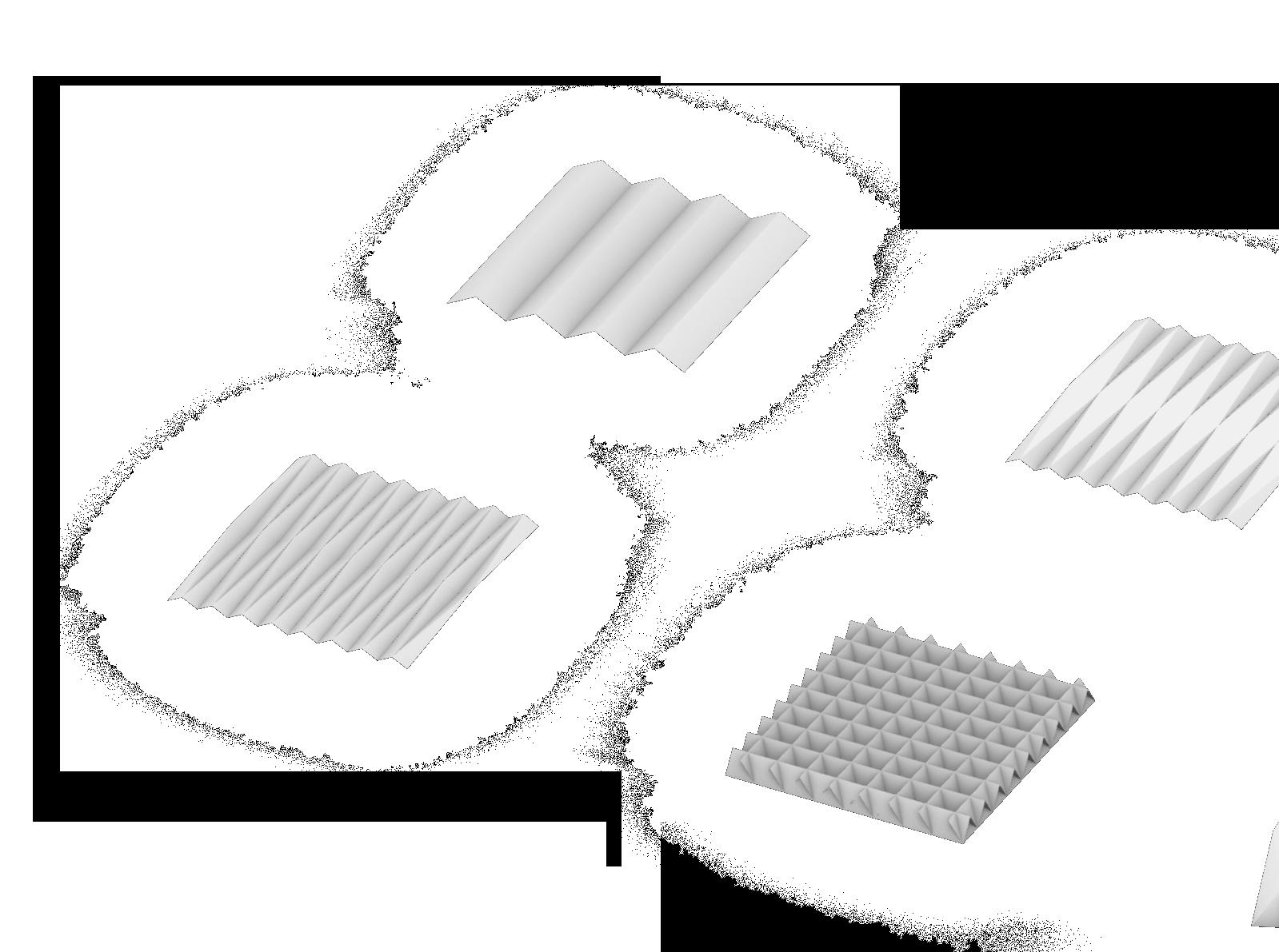
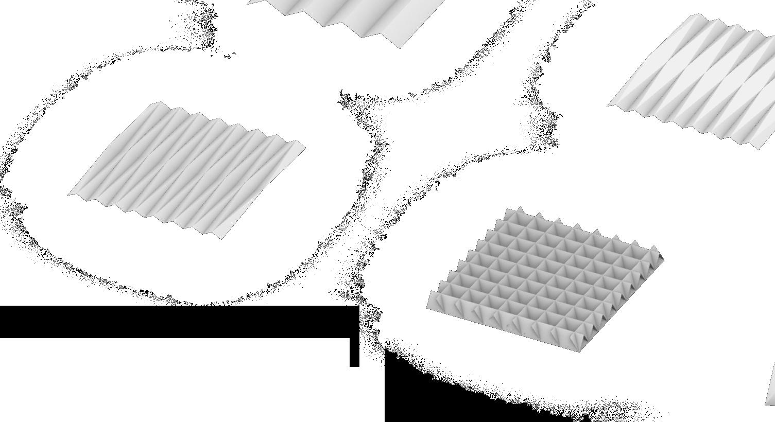
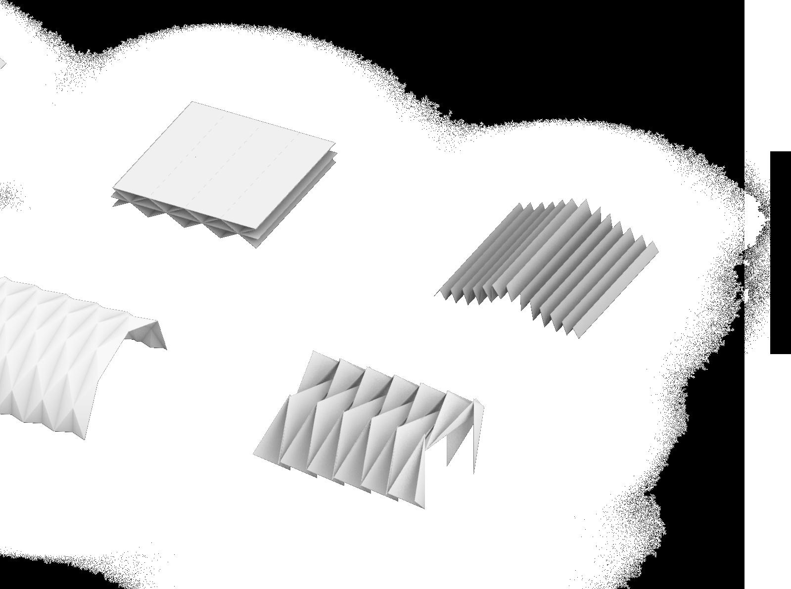
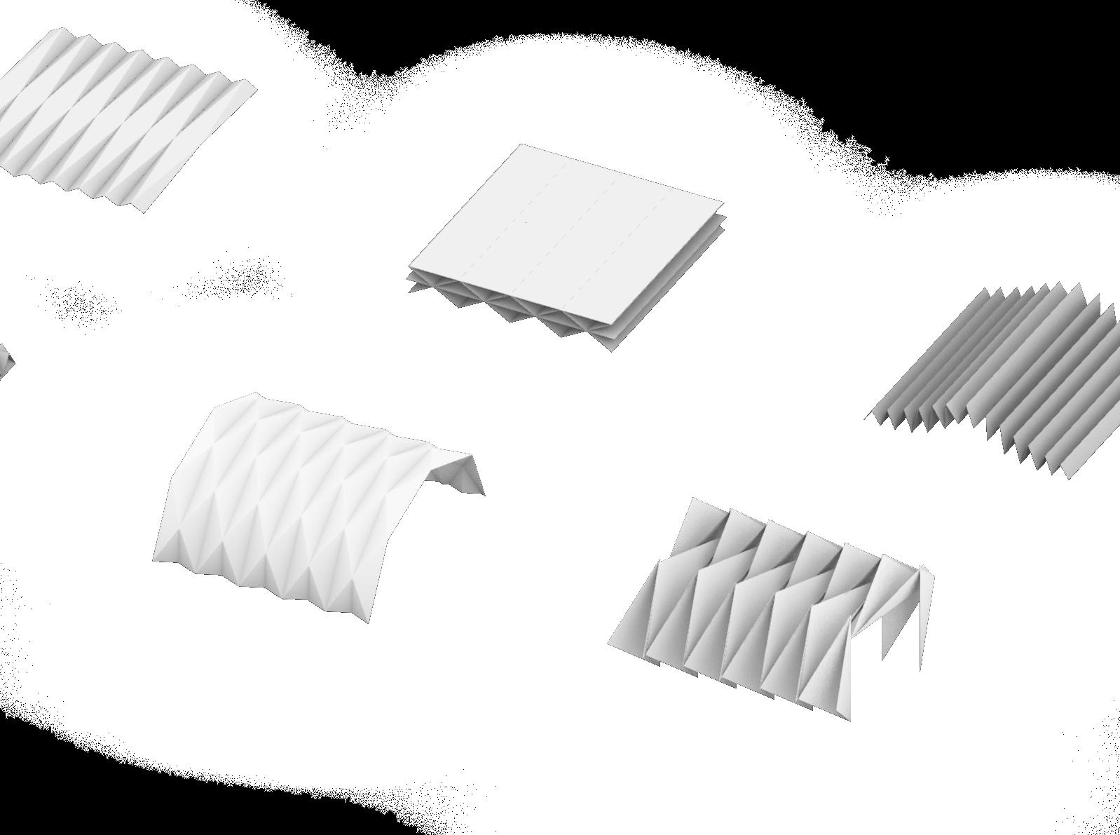
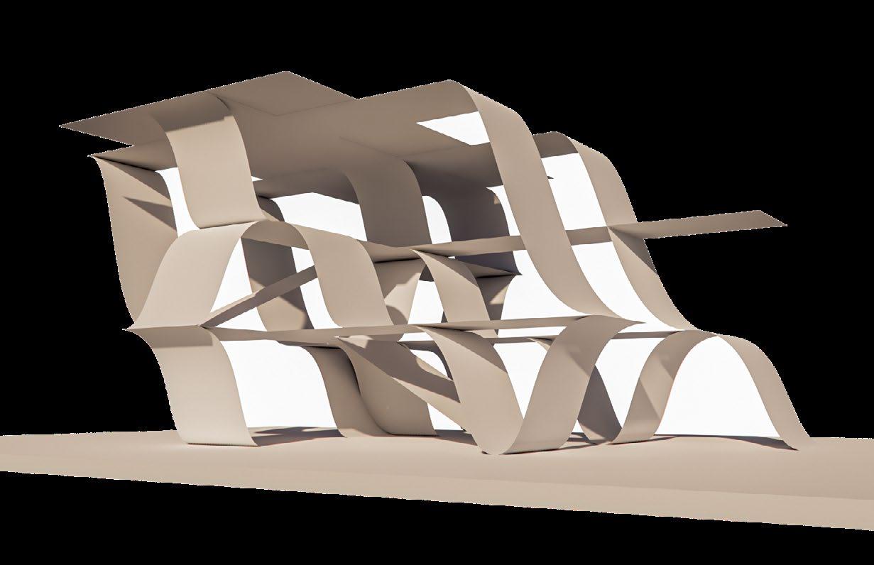
The structural language was abstracted into simplified folded surfaces to explore how repetition and inclination could generate spatial enclosure.
STRUCTURAL RHYTHM
This precedent was studied to understand how repetition and structural depth guide circulation while reinforcing spatial continuity.
INITIAL FOLD ITERATIONS
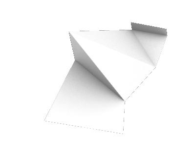
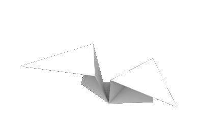
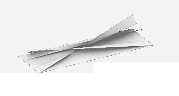
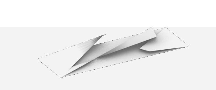
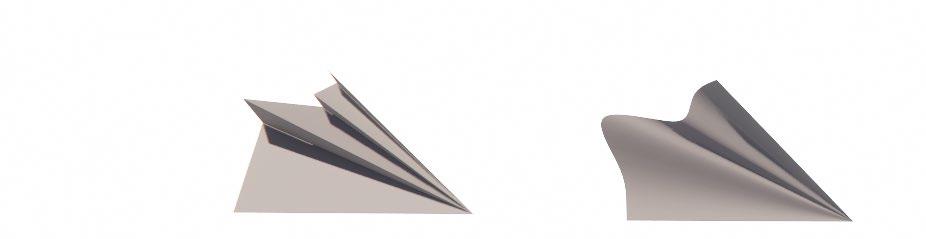
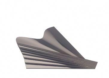
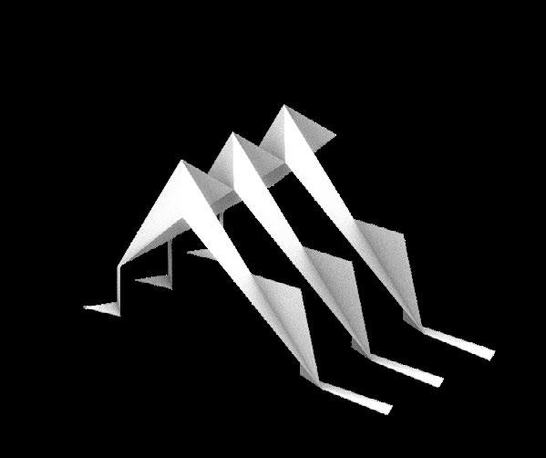
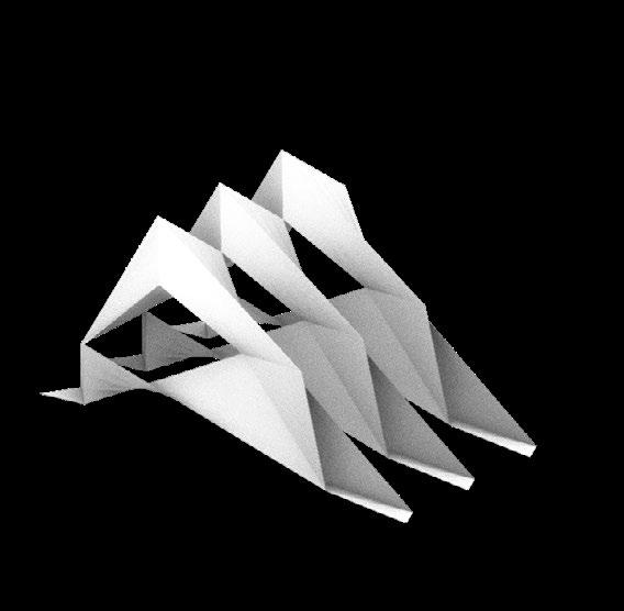
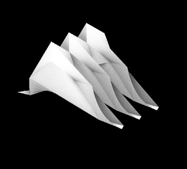
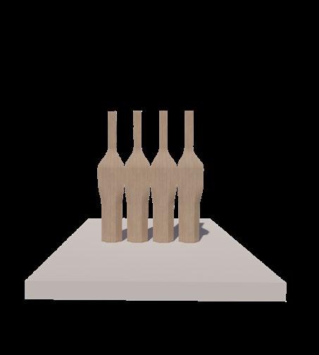
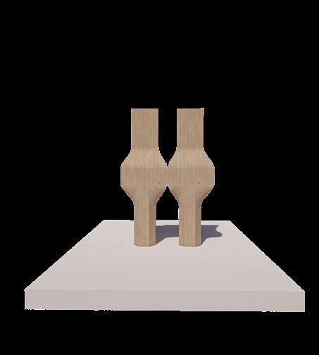
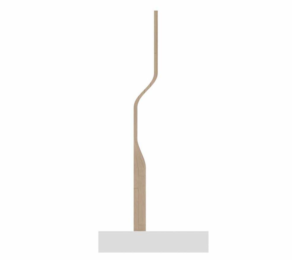
Early fold studies tested how compression, expansion and directional geometries could emerge from minimal surface manipulation.
RIBBED AGGREGATION
Folded rib elements were aggregated to investigate support into inhabitable
AGGREGATION
how repeated structures could transition from linear inhabitable spatial systems.
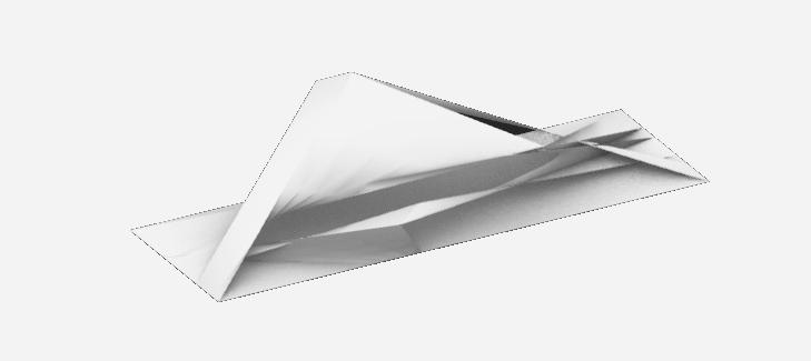
Intersecting folds were introduced to test how layered differentiated enclosure conditions
FOLD SYSTEMS
layered surfaces could intensify spatial depth and produce conditions at varying scales.
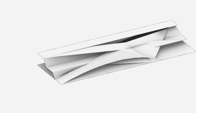
Folded surfaces were embedded within the landscape isolated objects and begin shaping circulation,
INTEGRATION
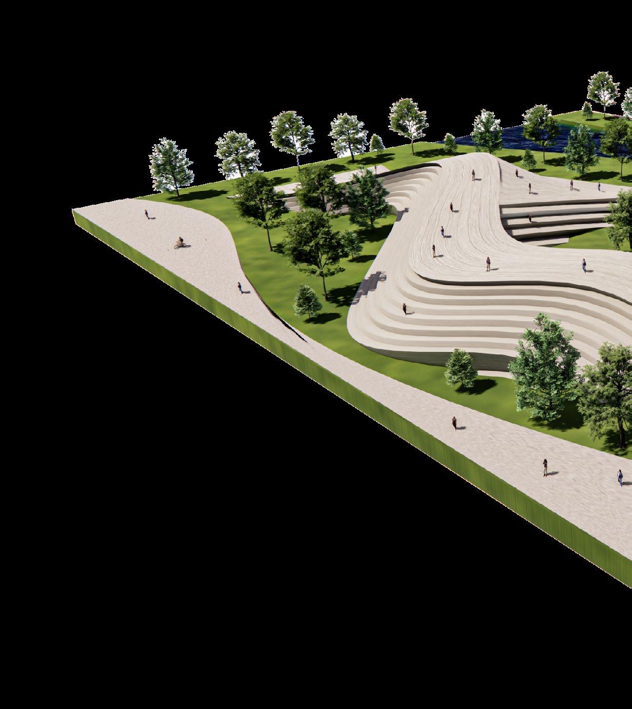
landscape to test how tectonic systems could extend beyond circulation, terrain and spatial occupation.
SPATIAL CONFIGURATIONS
Variations in folding and aggregation were explored to contrasting spatial and programmatic
CONFIGURATIONS
to test how a single tectonic language could generate programmatic conditions.
CADET CHAPEL - MODULAR STRUCTURE
The Cadet Chapel was analysed for its structural language, where repeated angular planes form both the architectural expression and the primary spatial order. Its vertical ‘folds’ create rhythm and directionality, offering a precedent for translating structural repetition into a more continuous folded surface system.
ARCHITECTURAL MOTIF
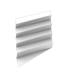
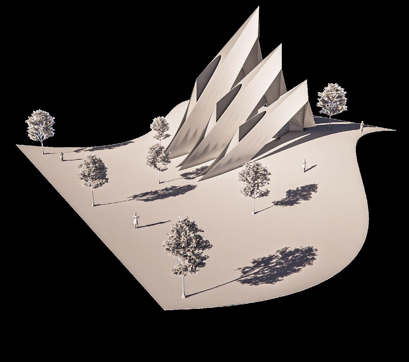
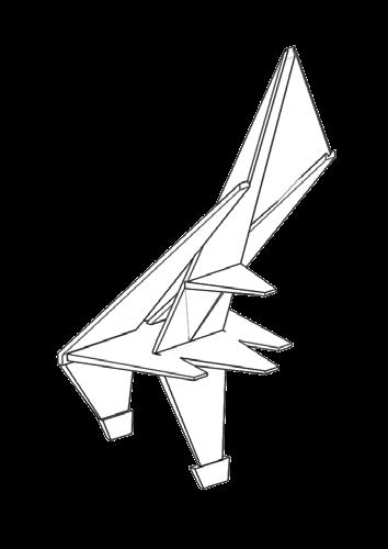
The folded verticality of the Cadet Chapel was abstracted into a simplified tectonic motif, translating repetitive structural planes into a continuous folded surface language capable of generating enclosure and directional movement.
FOLDING
KERFING
INTRODUCTION TO STRUCTURAL TIMBER - FOLDING + KERFING
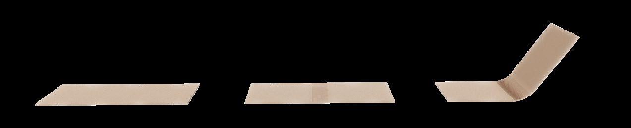
Folding and kerfing were tested as two methods of producing curvature/folds from flat timber elements. Kerfing allows smoother bending, while folding produces sharper structural lines and clear tectonic language
COMBINATION AND DEVELOPMENTAL DECISION
Folded and kerfed timber studies were combined to test how both bending systems could operate within a single structural language. The hybrid assembly explored a relationship between rigid folded plates and continuous curved surfaces before the project ultimately prioritised folded repetition for its structural stiffness and modular consistency.
*Research sources: IBOIS Laboratory for Timber Constructions, EPFL. Images and diagrams used/adpated for research purposes.
PLANAR FOLDING + TIMBER PROTOTYPE - IBOIS
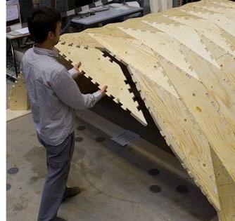
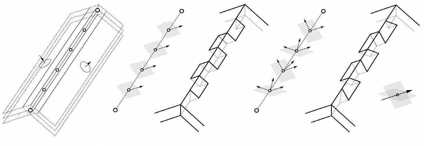
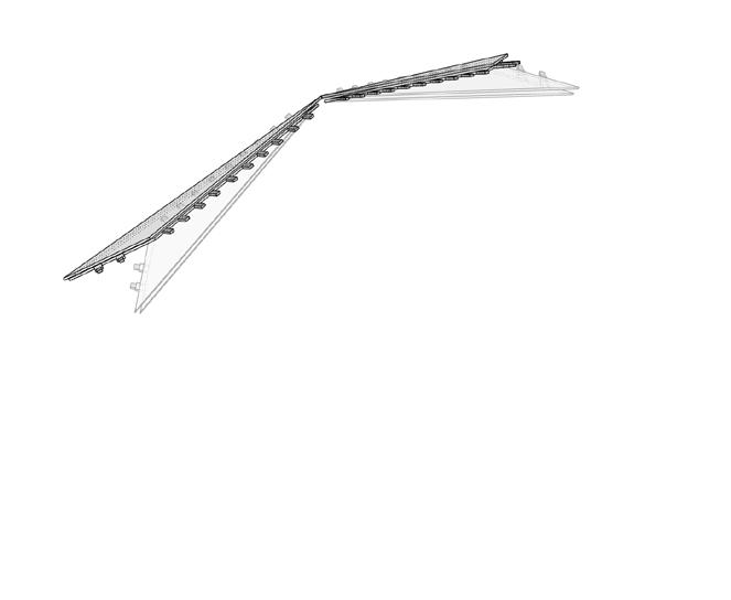
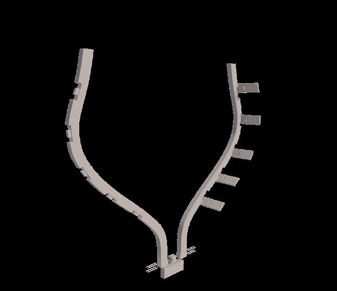
Utilising CLT within further developments, modern technology allows for newer tectonic language involving column free design, more commonly achieved with structural folding. Enabling structural stiffness, folding will allow larger spans. A method to ensure these folded plates can intersect is through using hinges that are sanded or CNC milled for angular accuracy.
*Research sources: IBOIS Laboratory for Timber Constructions, EPFL. Images and diagrams used/adpated for research purposes.
DOUBLE LAYERED CLT- IBOIS
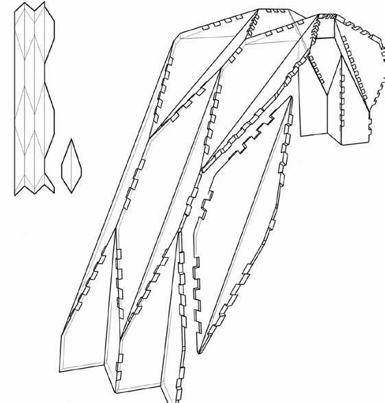
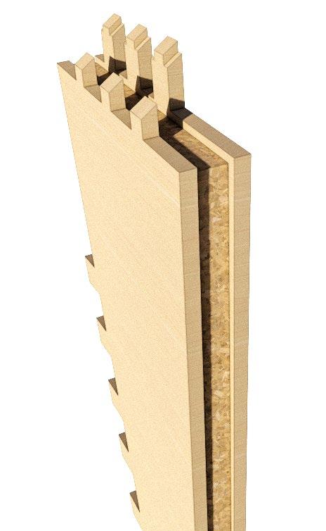
Theatre Vidy-Lausanne informed the development of a layered timber system capable of achieving large span flexibility (approx. up to 24m), exposed structural clarity alongside efficienct prefabricated assemblya contemporary construction method to emphasise wood-wood joinery and folding tectonic language.
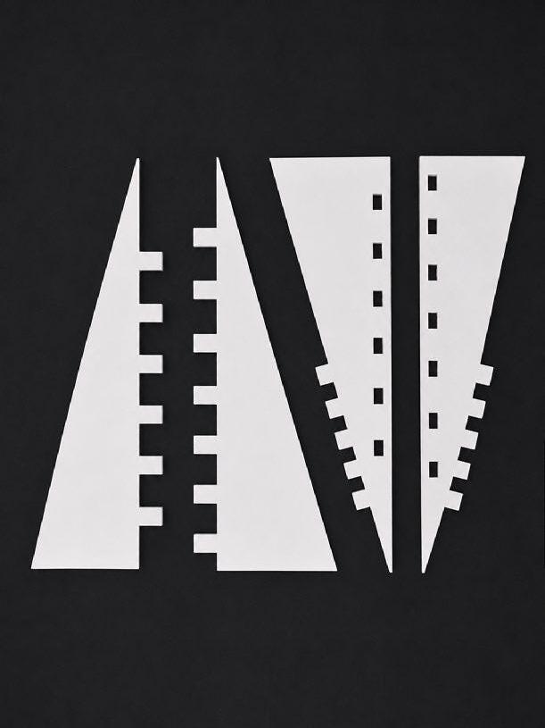
Double through tenon joint
Through tenon joint
TIMBER SHELL MATERIALITY
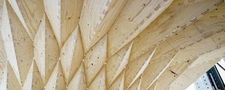
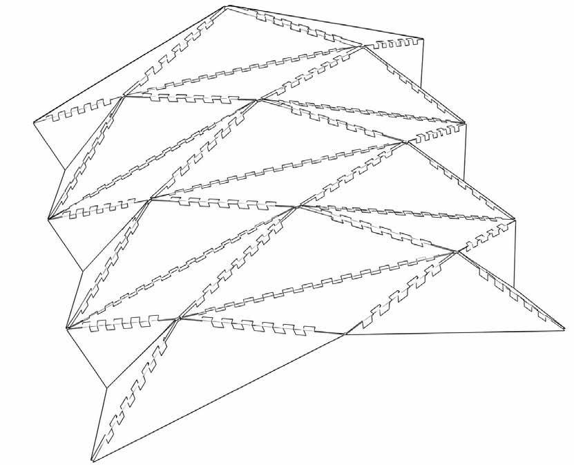
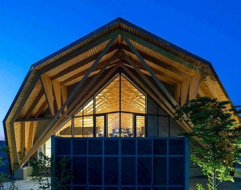
UEONA was studied as a precedent for demonstrating how folded timber systems can be fabricated through repeated modular components and lightweight panel assemblies.
ARTEFACT 1
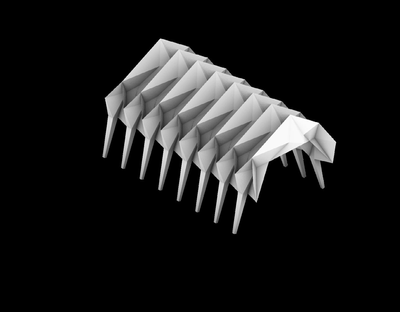
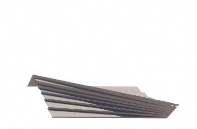
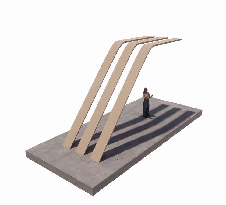
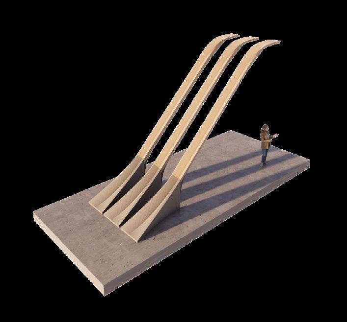
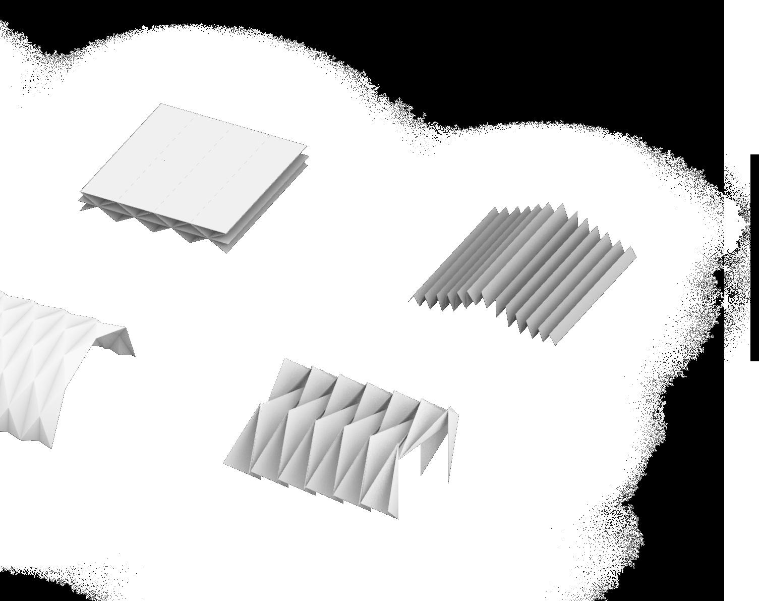
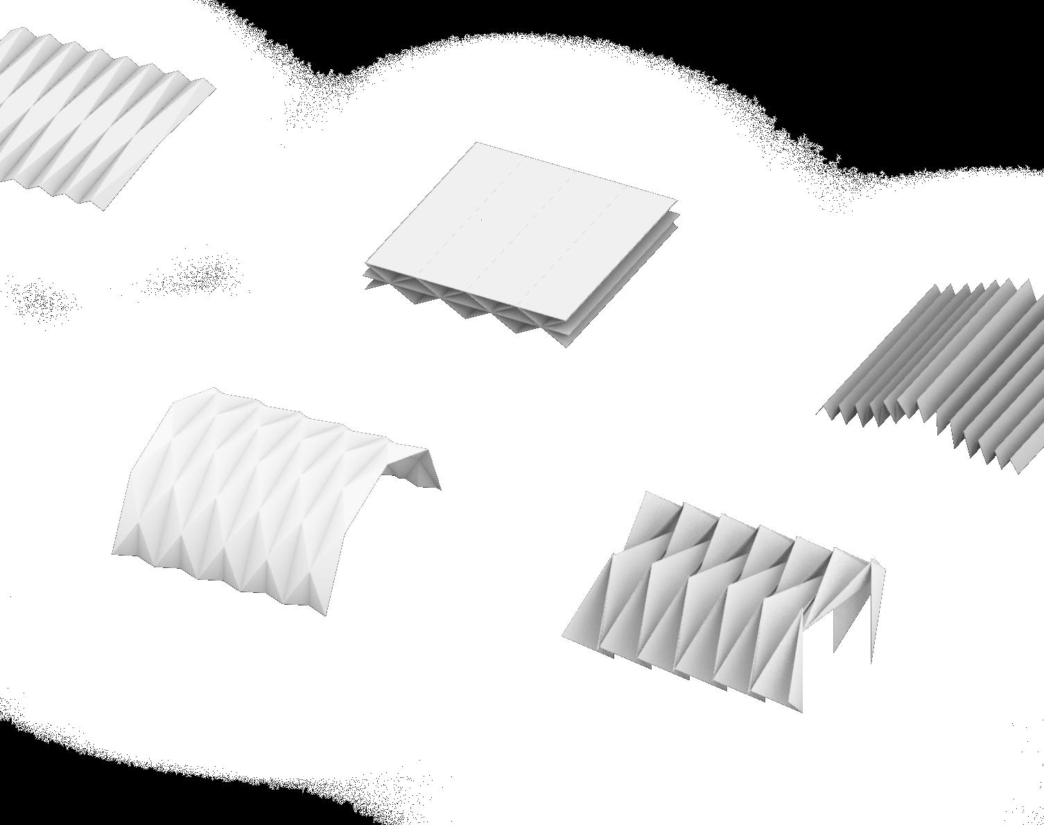
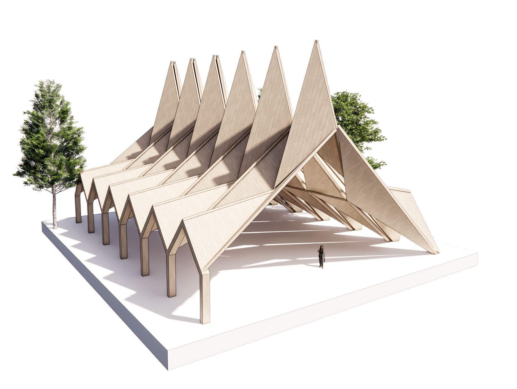
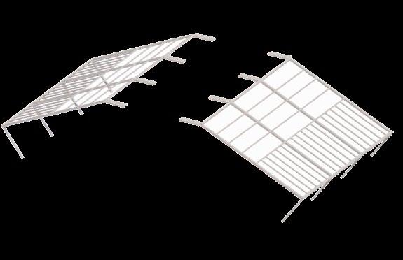
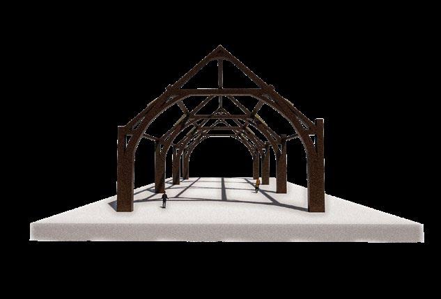
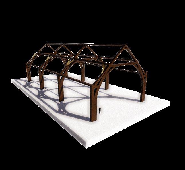
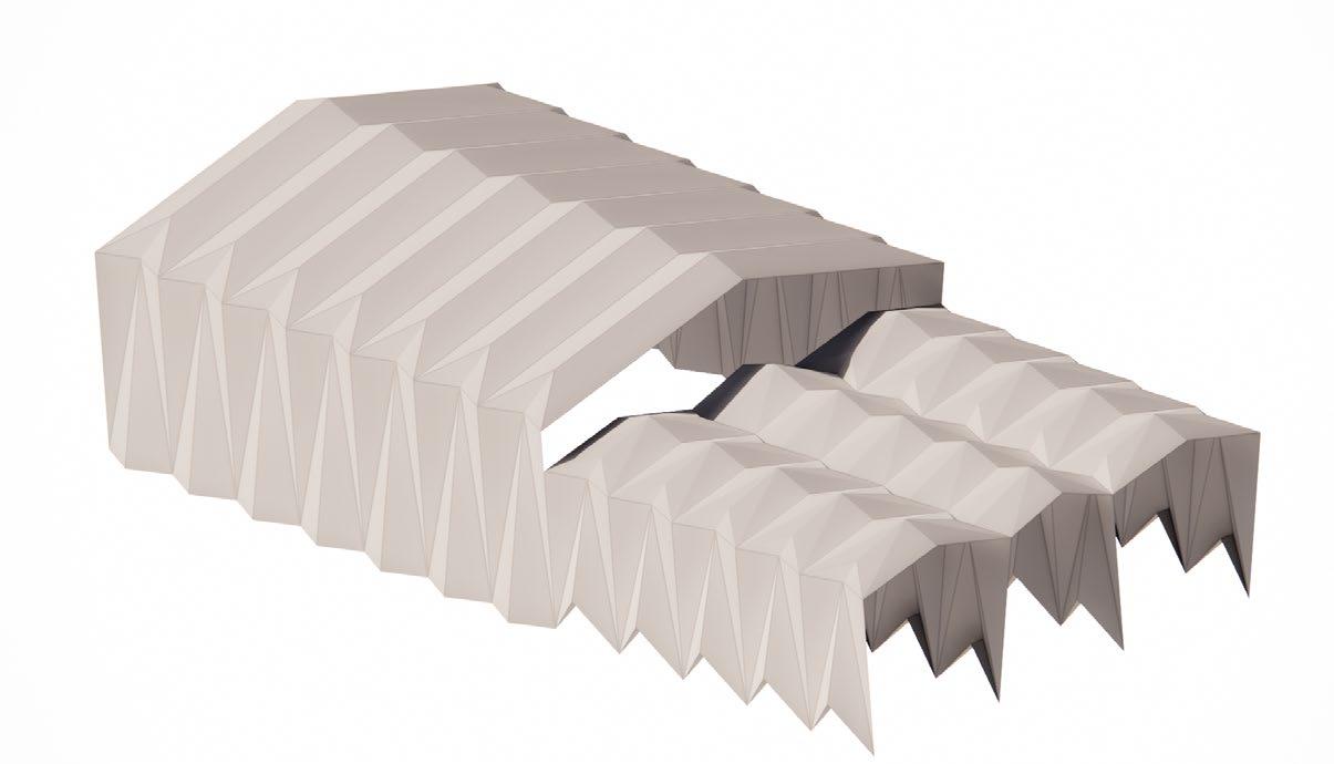
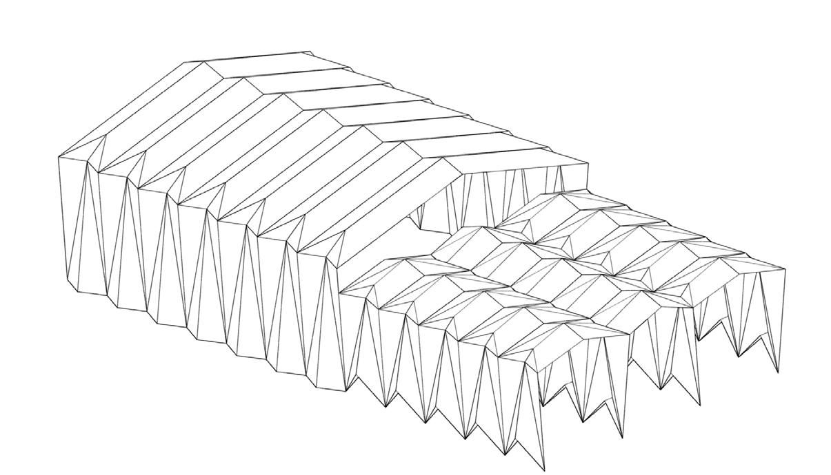
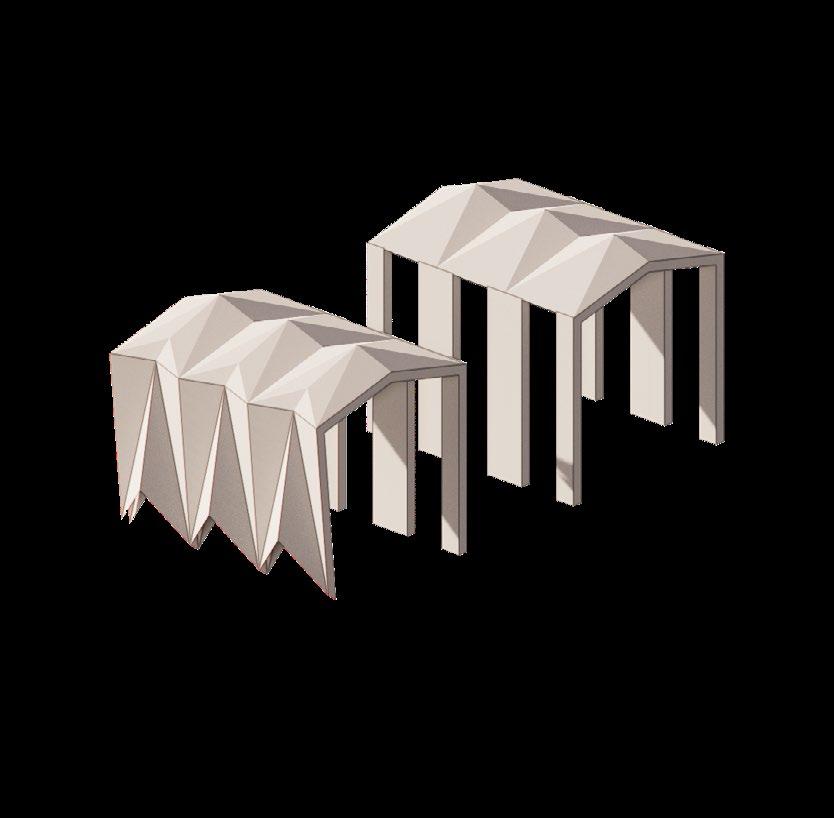
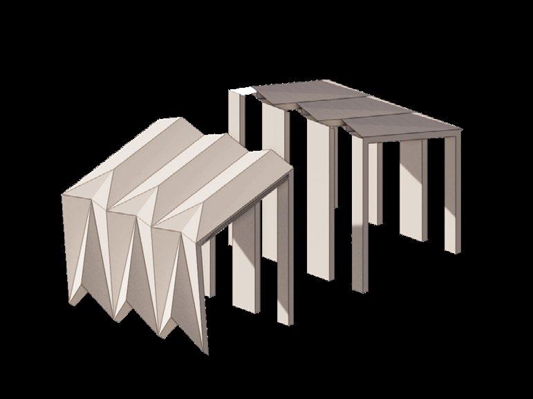
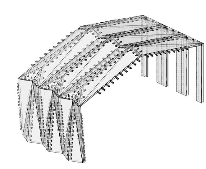
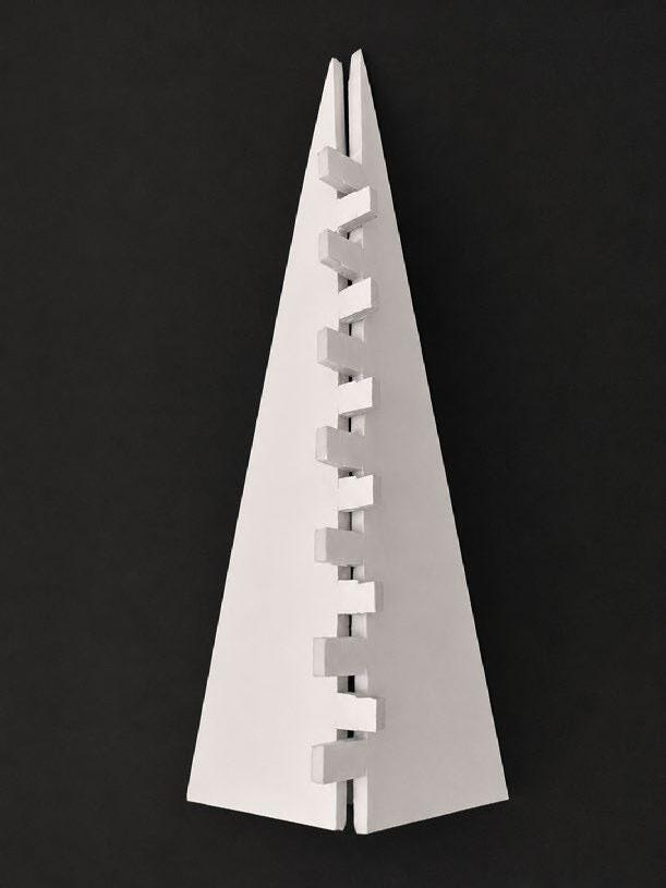
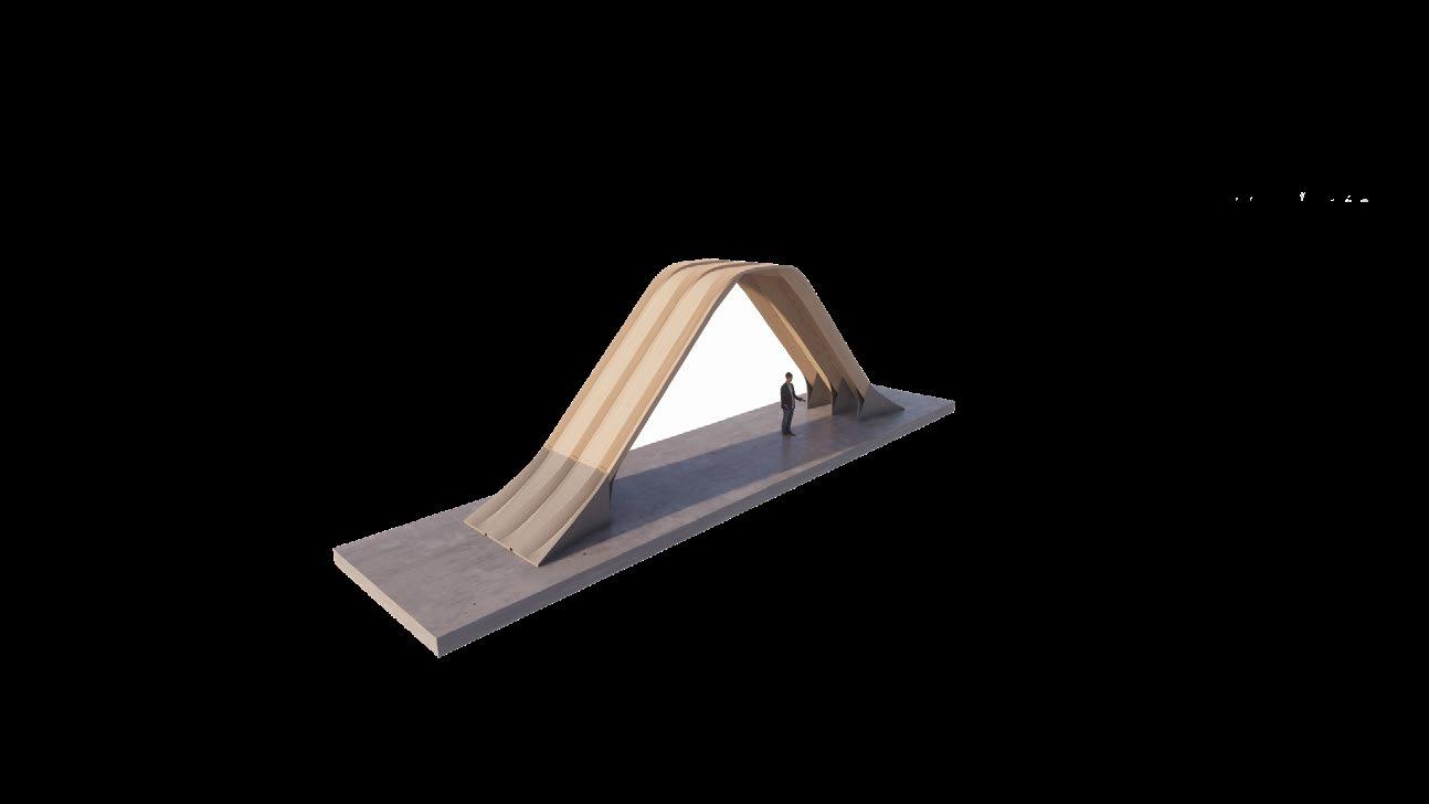
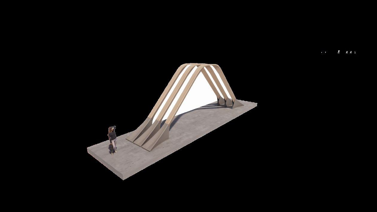
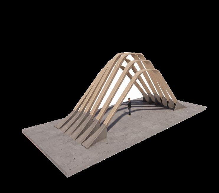
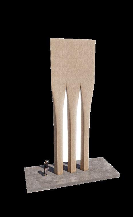
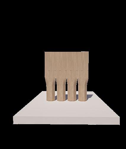
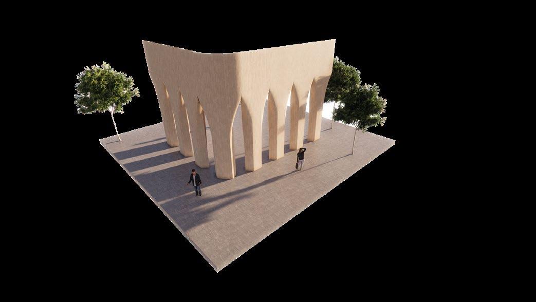
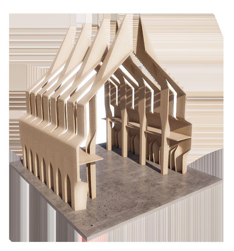
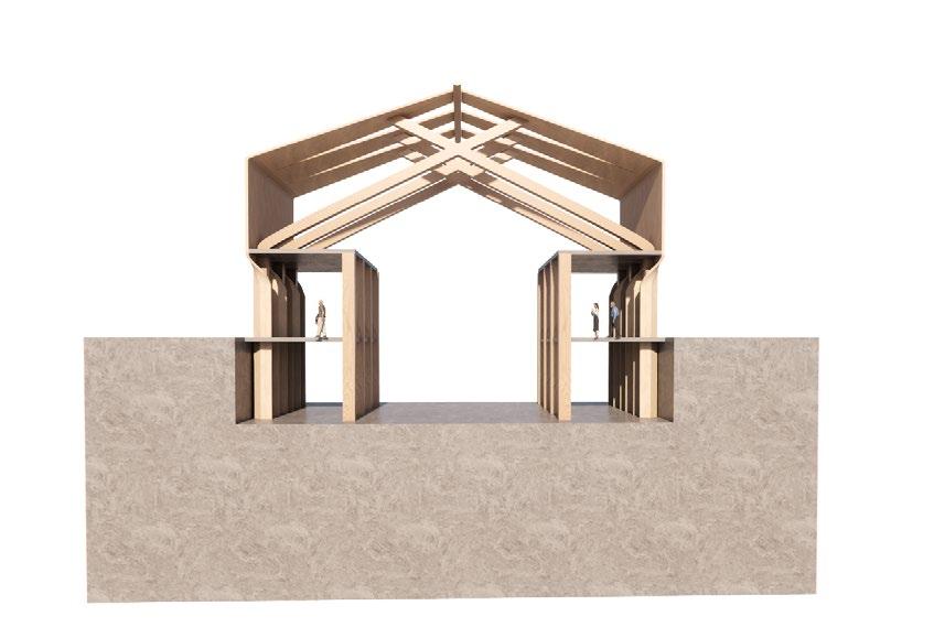
Repetitive folded bays were developed to test modular shell systems could establish structural rhythm and directional span.
ARTEFACT 2
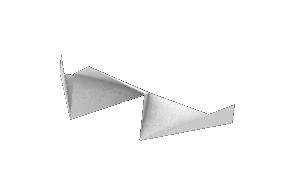
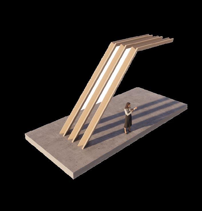
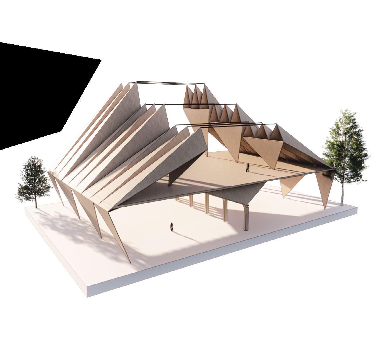
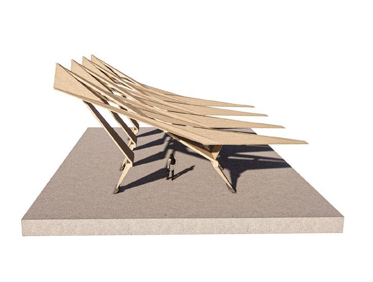
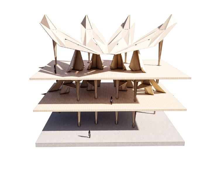
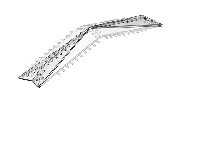
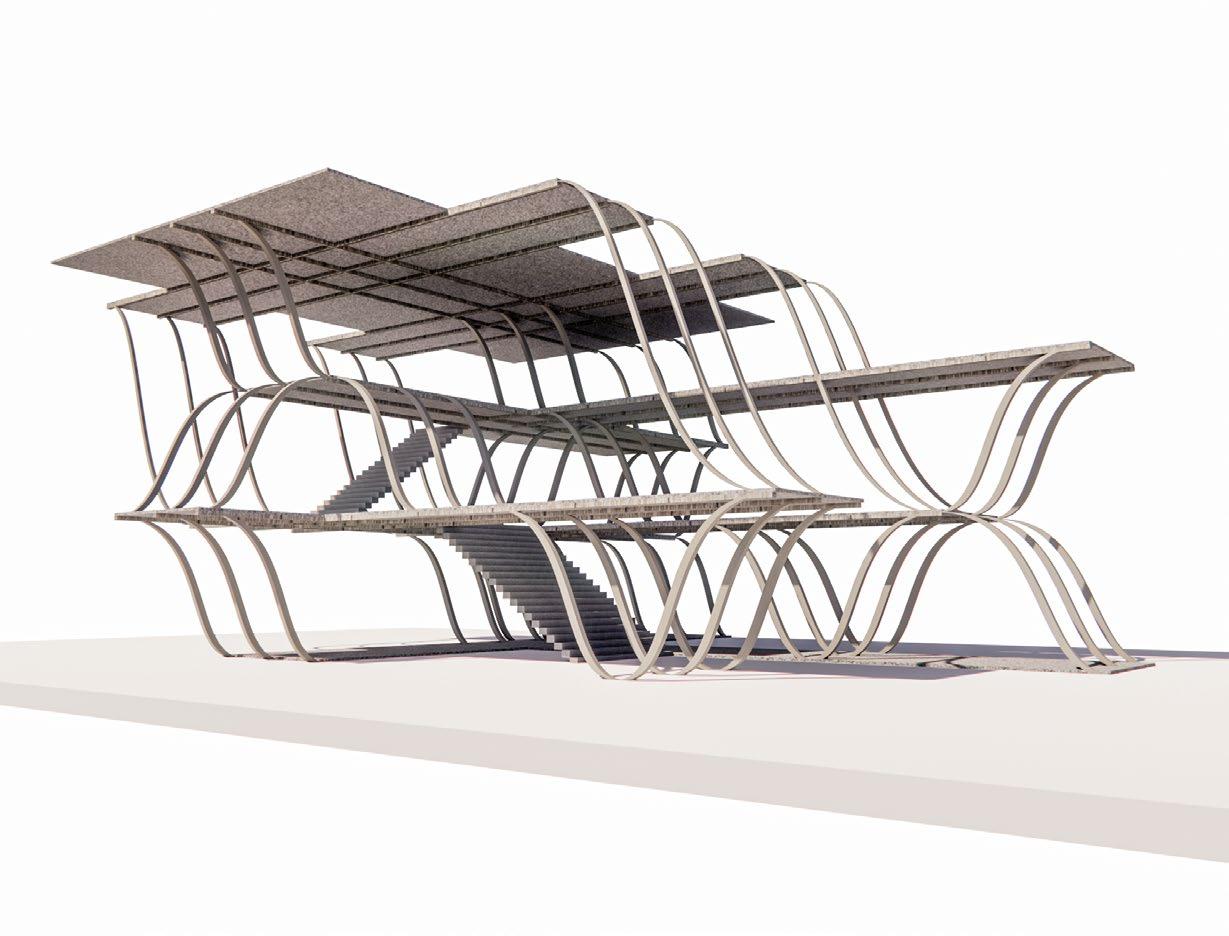
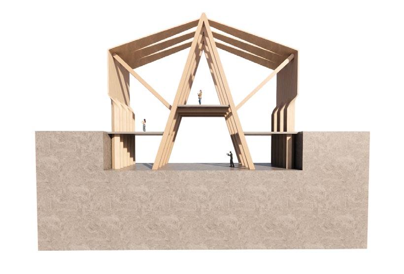
Folded roof planes were stepped vertically to establish spatial hierarchy and directional movement across the structural canopy.
ARTEFACT 3
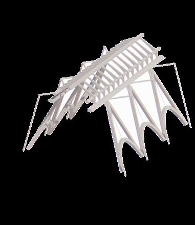
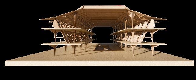
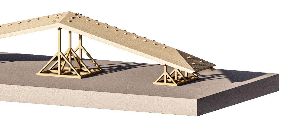
A secondary system of angled supports stabilises the folded roof, allowing the central span to remain open and visually lightweight.
ARTEFACT
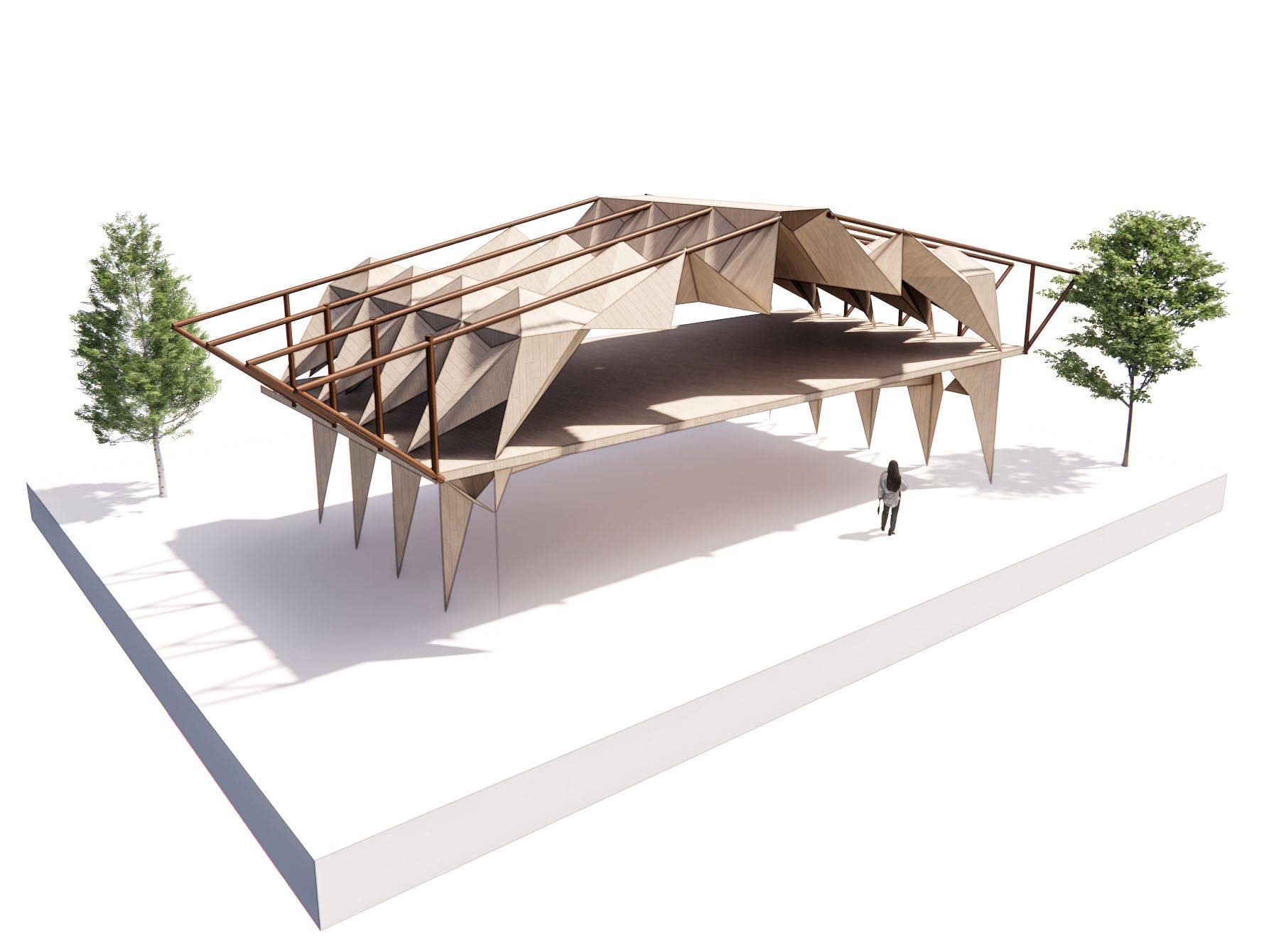
Asymmetrical folded shells were offset across the structure to destabilise the otherwise repetitive frame condition - gable-like openings mimic coastal and industrial forms and formulate a flush edge condition.
ARTEFACT 5
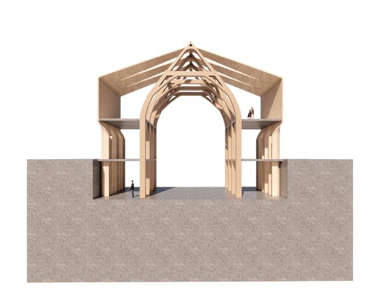
Hierarchy was introduced by varying the height and scale of repeated folded elements across the structure.
ARTEFACT 6
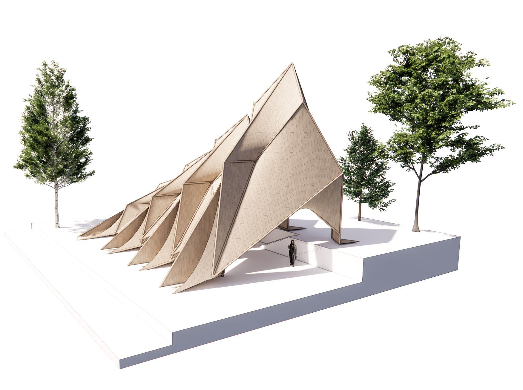
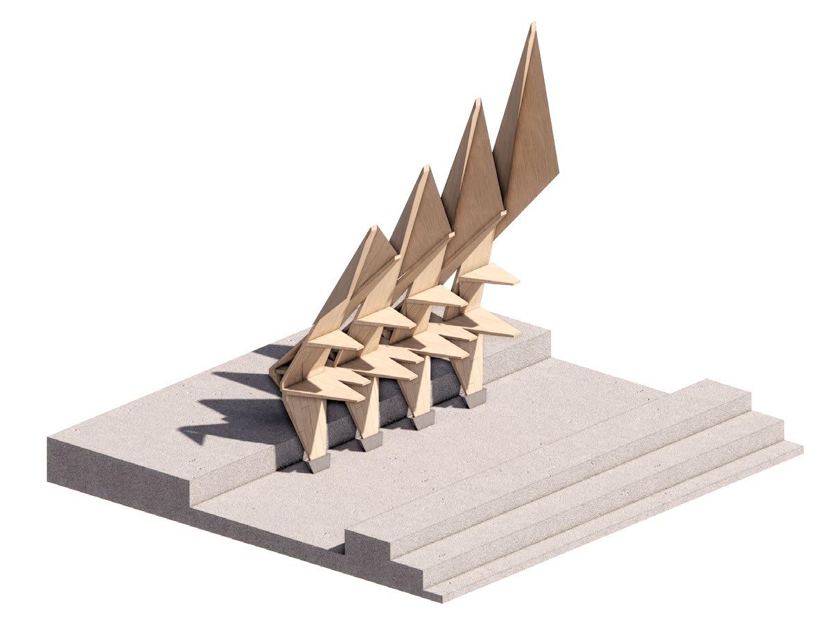
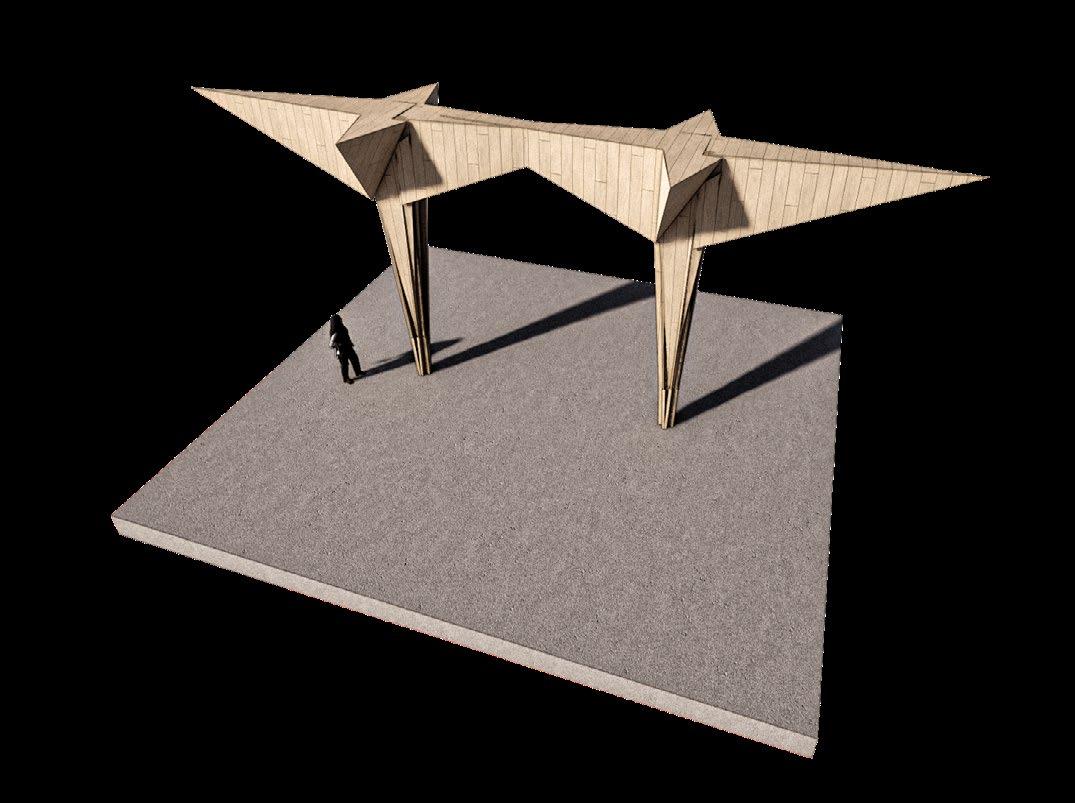
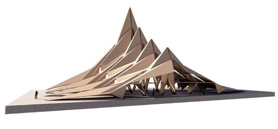
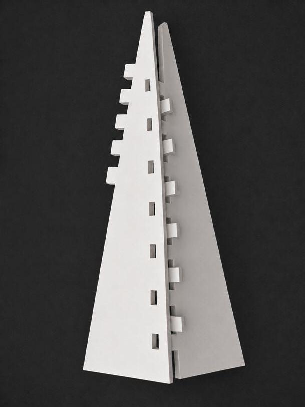
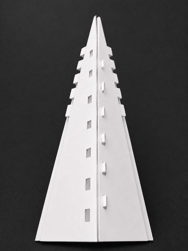
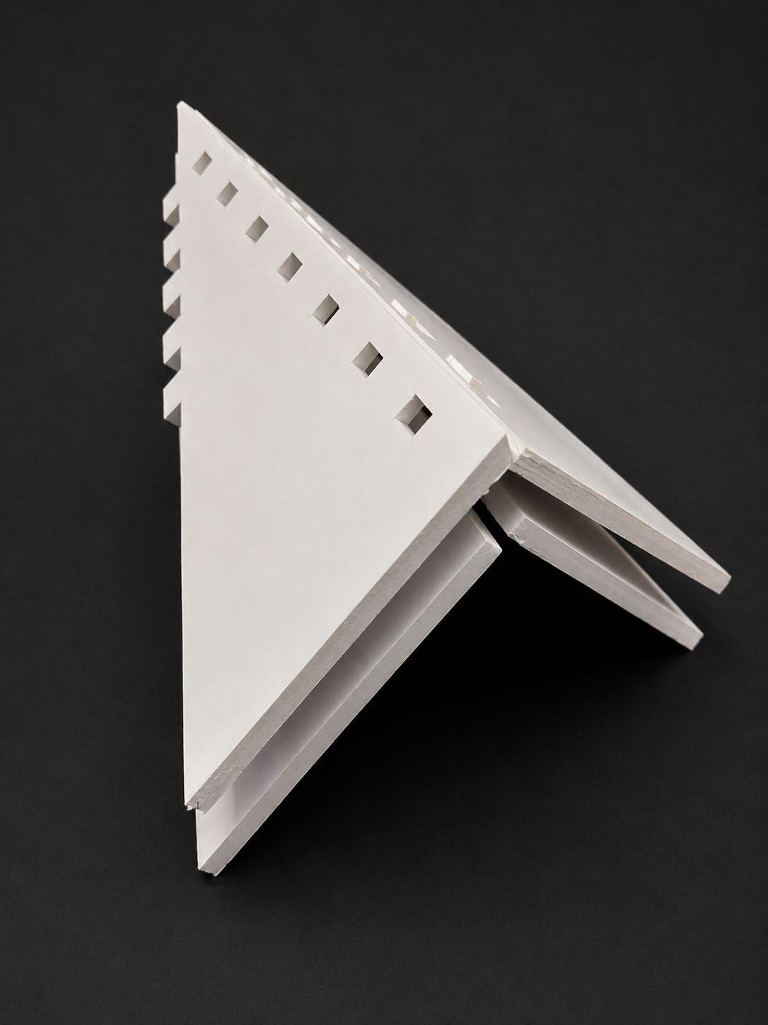
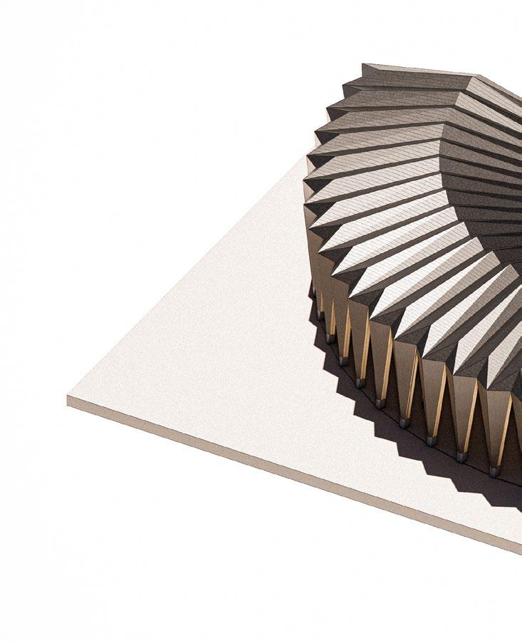
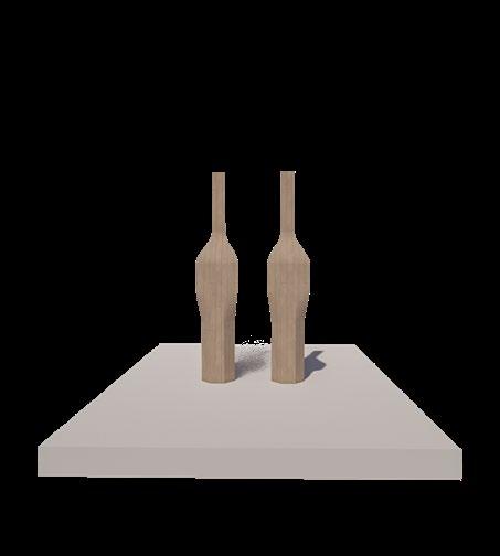
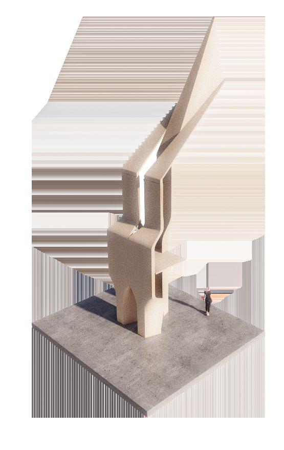
Inspired by the Cadet Chapel, this repeated shell system was compressed into a concentrated vertical structure to intensify hierarchy and structural focus.
GARE DE MONS STRUCTURAL FOLDING INSPIRATION / UENOA MATERIALITY & FOLDING INSPIRATION
FRAGMENT EXTRACTION
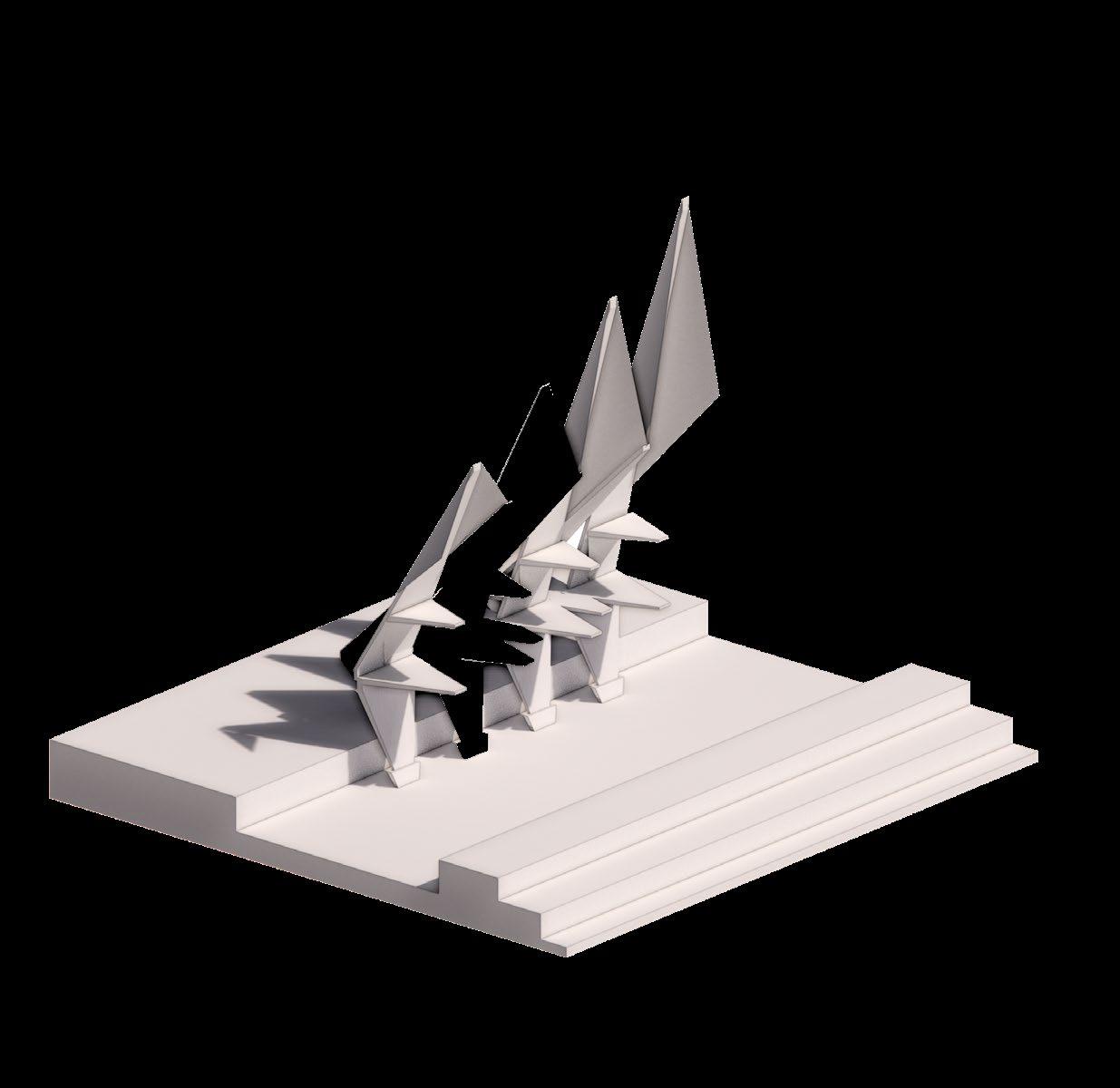
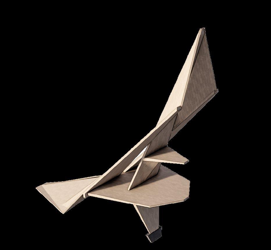
Structural fragments from Artefact 6 were extracted and recombined to test relationships between ribbed aggregation and shell hierarchy based on the dual layering of abstracted plates during initial testing.
MODULAR
DEVELOPMENT 1 - COLUMN STUDY
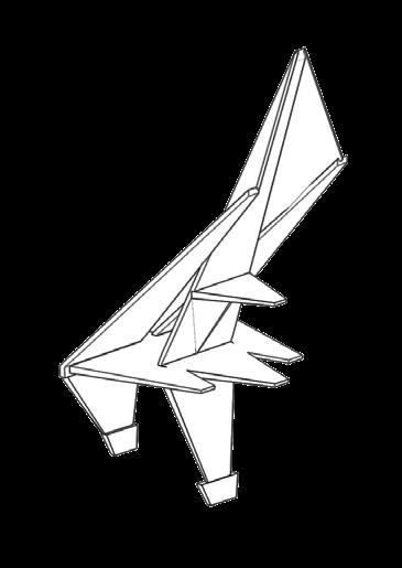
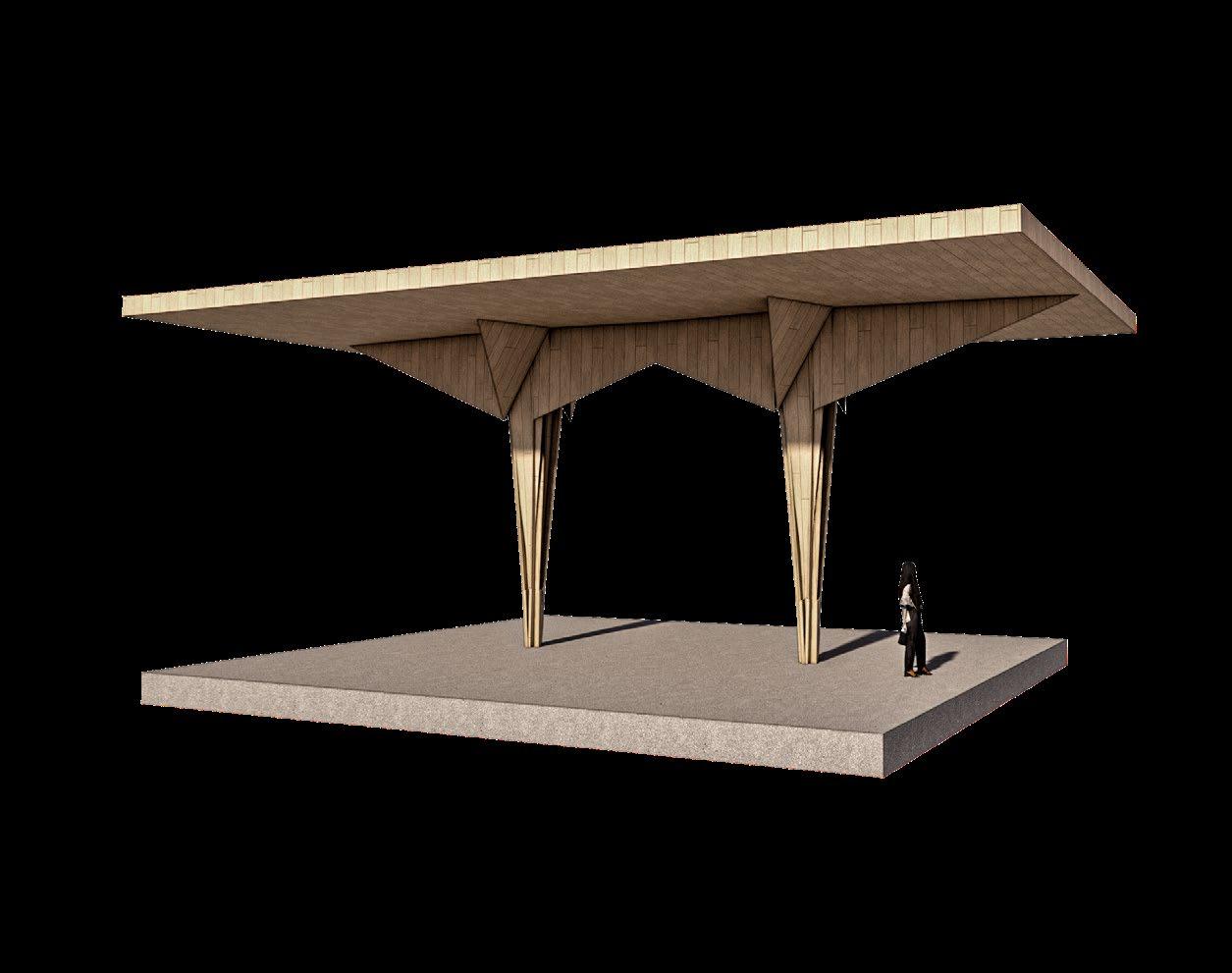
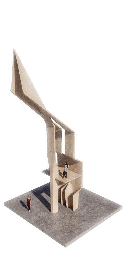
Folded shell fragments were compressed into vertical support points, beginning to translate the roof language into a column condition, enabling openings and floor sub-structure.
MODULAR DEVELOPMENT 2 - MOTIF GENERATION
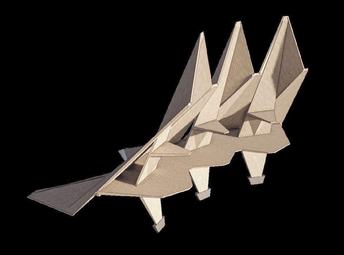
Extracted fragments developed from Artefact 6 were recombined as repeatable modules, testing how the same folded language could produce both upright supports and clustered shell formations.
MODULAR DEVELOPMENT 3 - AMALGAMATION
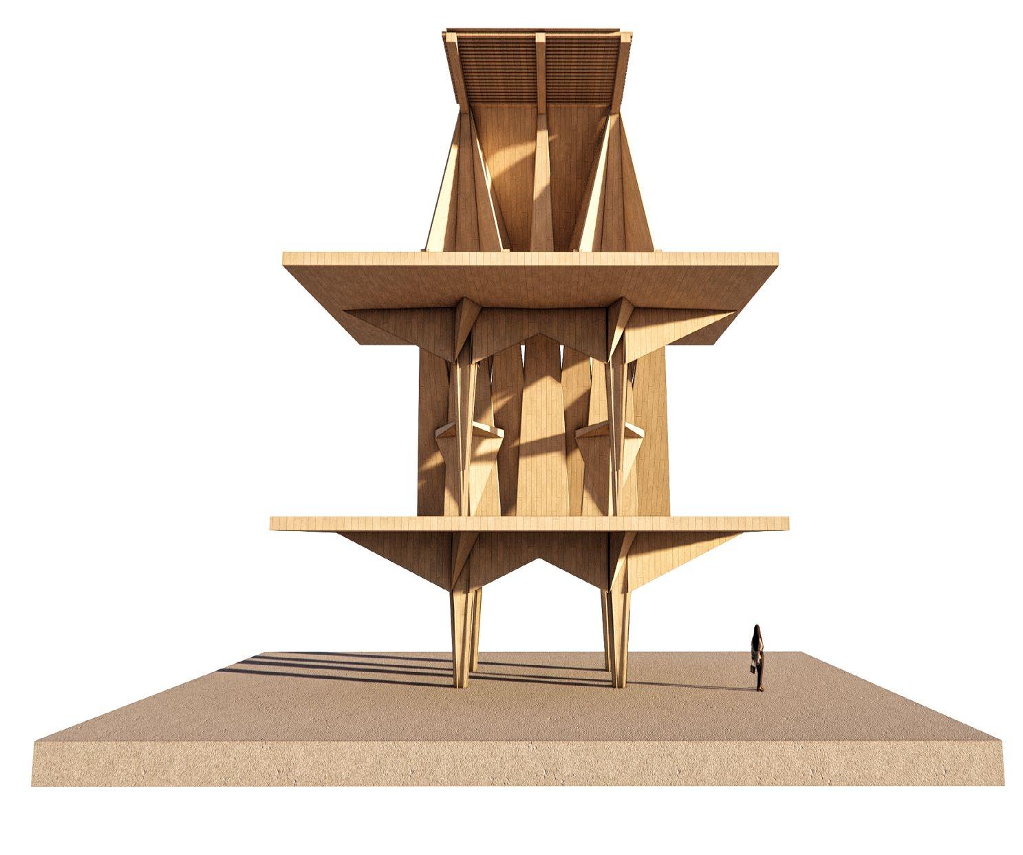
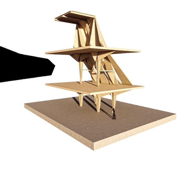
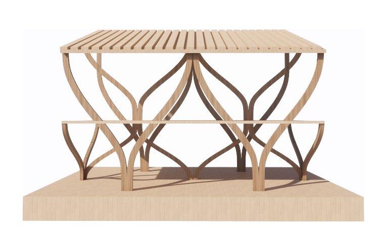
Concentrated column study was combined with the folded surface motif to test how vertical support and shell geometry could operate as a single structural system.
MODULAR DEVELOPMENT 4 - ENCLOSURE
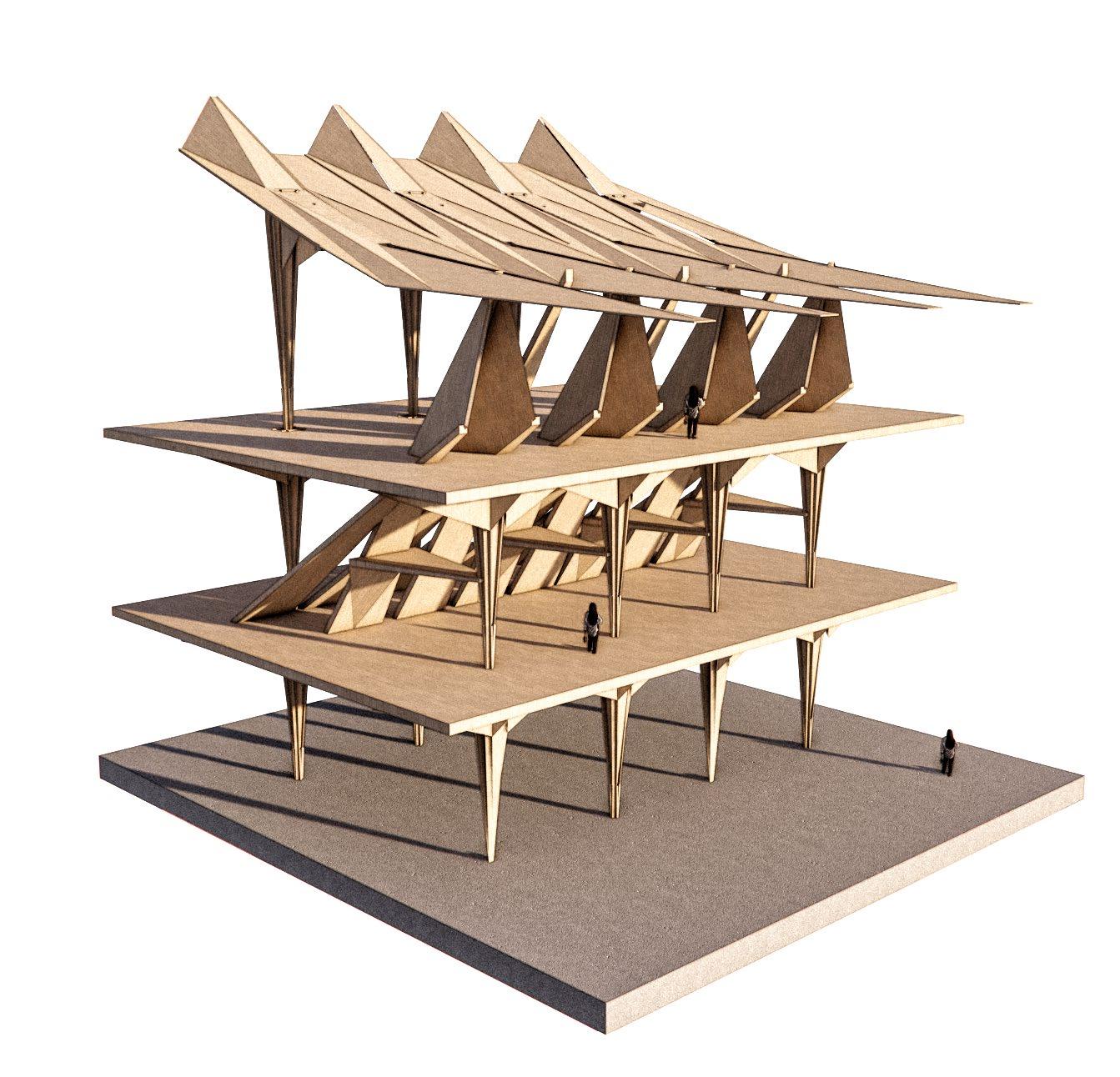
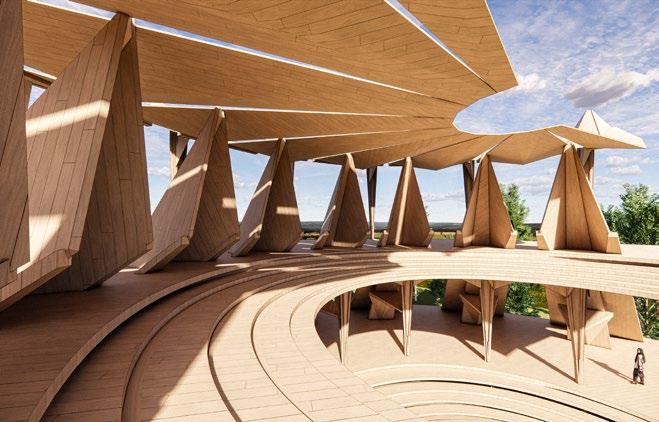
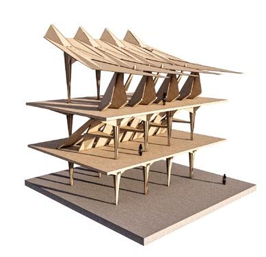
Further motif generation and layered floor plates were inserted between the primary timber frames, producing a stacked assembly that reinforces hierarchy between structure and occupied space.
FRAGMENT REPLICATION
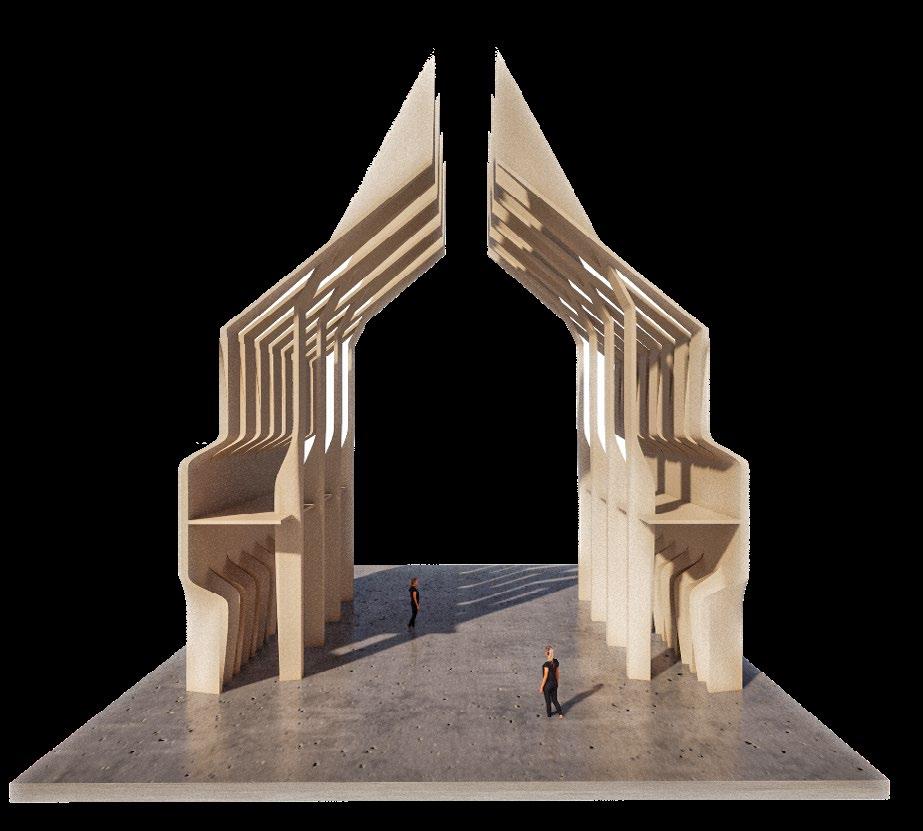
The developed structural fragment was replicated across could organise circulation, enclosure and
REPLICATION
across the site to test how a singular tectonic module and programme at architectural scale.
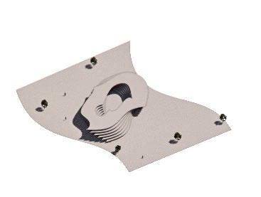
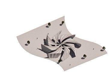
The replicated structural module reorganised into a radial can generate centralised spaces to strategically place could be used in conjunction with regular modules
VIEWING PLATFORM
radial arrangement to test how repeated folded frames place programme of higher importance or relevance. This modules to create variations of the same tectonic.
Multiple organisations derived from the earlier extracted language can adapt to different spatial conditions
FURTHER DEVELOPMENTS
extracted tectonic module examine how the same folded conditions through changes in span or structural hierarchy.
SECTION 2
CONTEXTUAL RESEARCH
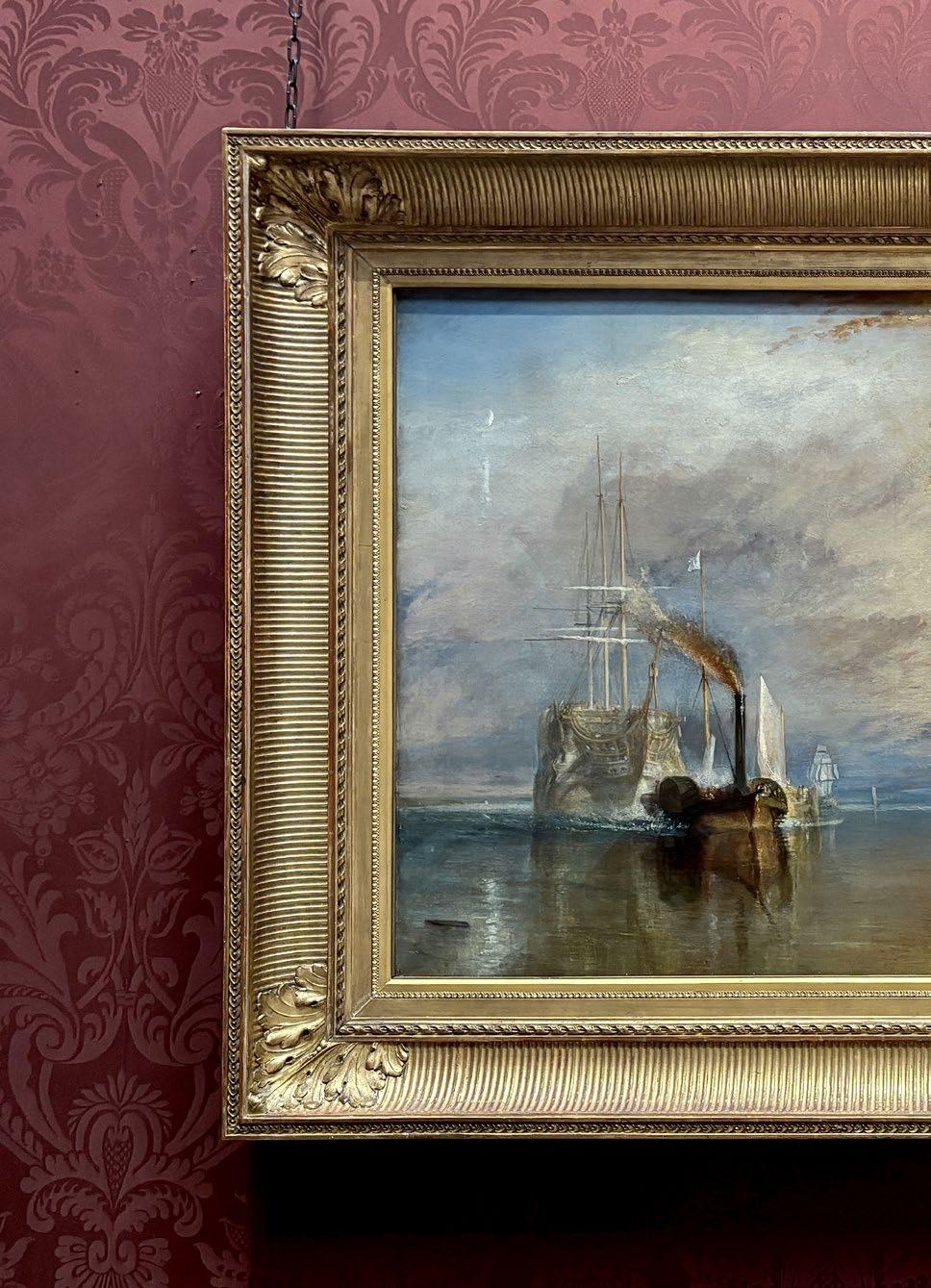
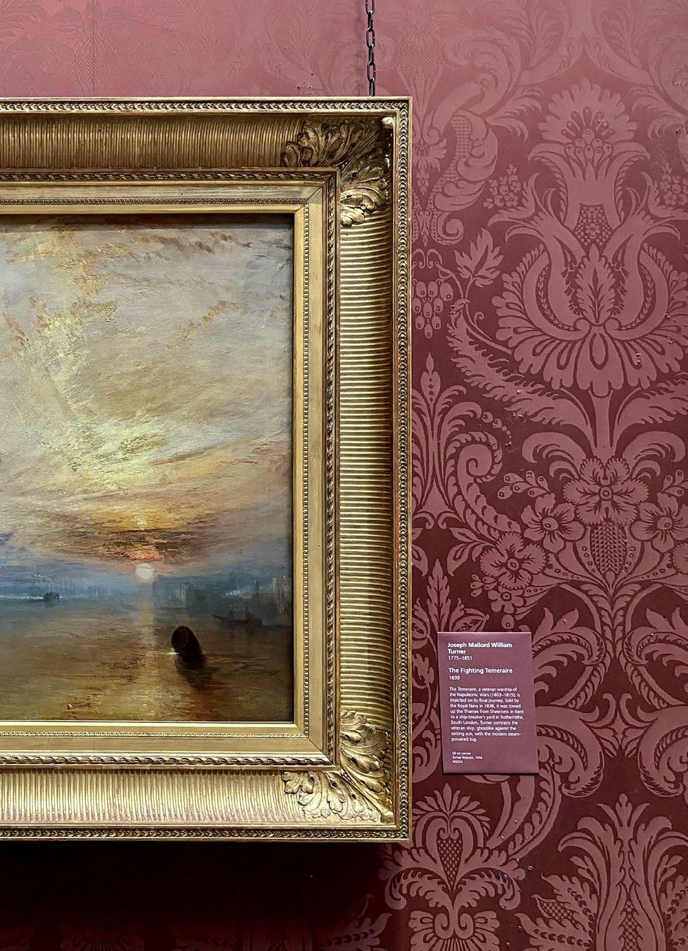
THE FIGHTING
Turner’s The Fighting Temeraire became symbolic of traditional maritime craft by emerging mechanised infrastructure, project
FIGHTING TEMERAIRE
of industrial transition, marking the displacement of infrastructure, ultimately determining the basis of this
brief.
FRAGMENTED PLANNING + INVESTMENT OCTOBER
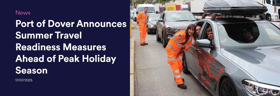
Positioned centrally within the proposed South Coast operational network, Shoreham Harbour establishes a coordinated regional ferry node capable of reduing infrastructural fragmentation, improving freight distribution and strengthening long-term cross-channel resilience across the southern corridor.
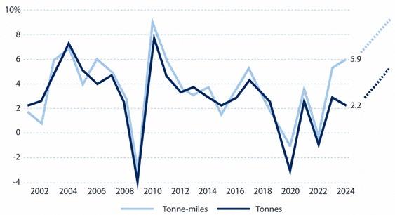
Growth in Maritime Trade with Annual Trajectory (%)
Southern node - most intensive UK ferry corridor
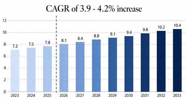
Global Passenger Ferries Market 2023-2033 Trajectory (B£)
CURRENT + PROJECTED FERRY TRANSIT + TRADE
Local Sussex hardwood and Scandinavian timber were identified to establish a material palette informed by existing regional sourcing, Nordic construction traditions and maritime timber craft.
EAST SCOTLAND
WEST SCOTLAND
WALES
NORTH-WEST
NORTH-EAST
SOUTH-EAST
SOUTH-WEST
UK-Wide New Operational Zones
Project Focal Zone
to Bilbao & Santander
Portsmouth
Southampton
Poole
Isle
Shoreham Newhaven
EAST/EAST-MIDLANDS
Cherbourg
Existing Ferry Links
New Operations
Guernsey
Jersey
Roscoff
Caen
Dover
Calais
Le
REGIONAL OPERATIONAL ZONING
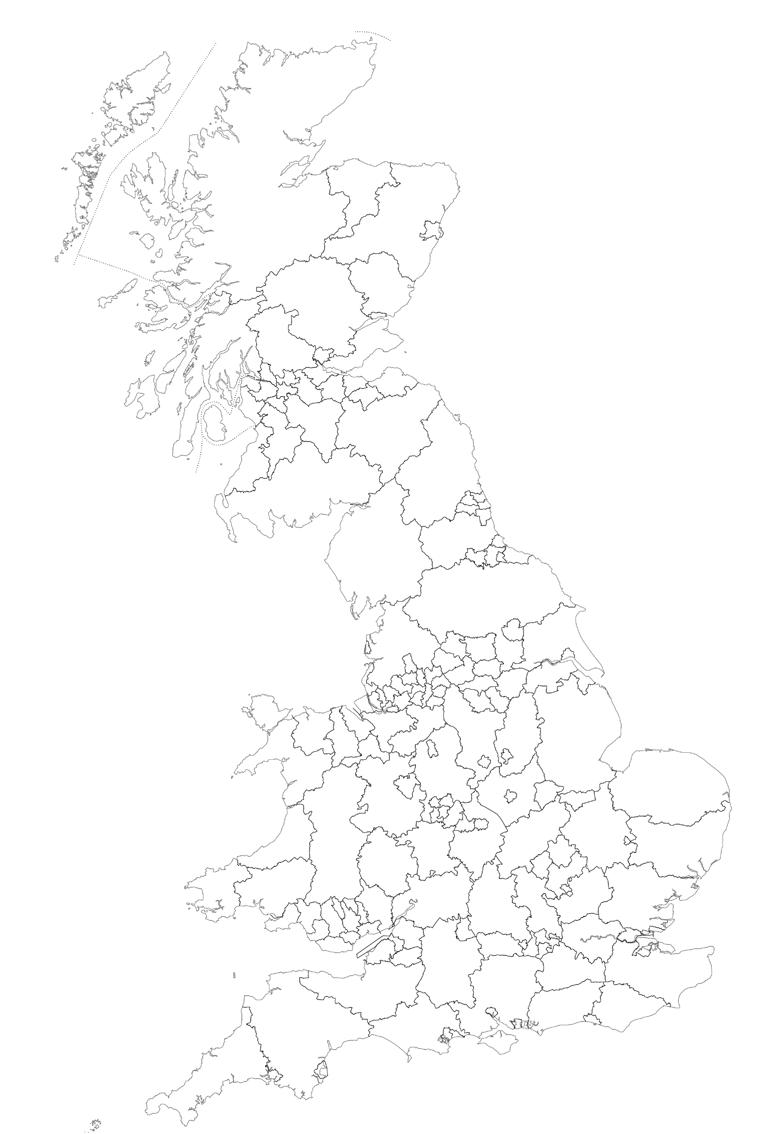
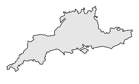
Regional operational zoning was introduced to establish a more coordinated maritime network capable of responding to increasing cross-channel pressure, trade dependency and corridor-wide logistical fragmentation. The South-East is the primary focal point of the project due to its prominence in transit and trade with exponential pressures.
Of Wight
Dunkirk
Havre
Dieppe
Disjointed Governance
Poor Disruption Response
PROGRAMME
FERRY TERMINAL - MARITIME HUB
Weak Economic Integration
Inefficient Corridor-Wide Planning
CHALLENGES UNDER FRAGMENTATION
VISION
ESTABLISH A SOUTH COAST MARITIME OPERATIONS HUB, OPERATING THE UK’S MOST INTENSIVE FERRY CORRIDOR
BETWEEN POOLE AND DOVER AND ITS CROSSCHANNEL CONNECTIONS
Centralised Operational Control
Coordinated Management
Greater Transport Efficiency
THE CHANNEL CORRIDOR
OPERATIONAL SYSTEM
System Level Efficiency
BENEFITS UNDER OPERATIONAL AUTHORITY
UK - NATIONAL MARITIME AUTHORITY
SOUTH EAST - SHOREHAM HUB
POOLE - DOVER & CONNECTIONS
OPERATIONAL BENEFTIS
Centralised operational management improves corridor-wide coordination, transport efficiency and economic integration across the South Coast maritime network.
UPSKILLING THE TRADITIONAL + DEINDUSTRIALISED
Through apprenticeship-led maritime construction, timber fabrication and heritage preservation programmes, the proposal reintroduces skilled employment, education and commercial value while supporting a sustainable future within the maritime industry and reducing road congestion.
THE ORIGINAL THE INDUSTRIAL REPLACEMENTS THE ORIGINAL DISCOVERED
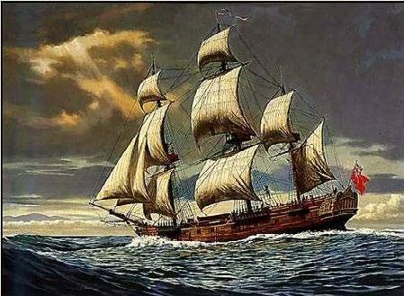
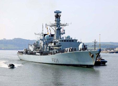
PORTSMOUTH, HAMPSHIREHMS VICTORY + MARY ROSE
SHOREHAM, WEST SUSSEX - OPERATIONAL NODE
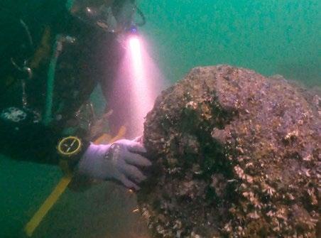
DEAL, KENTHMS NORTHUMBERLAND WRECKAGE
CONTINUITY THROUGH INDUSTRIAL TRANSITION
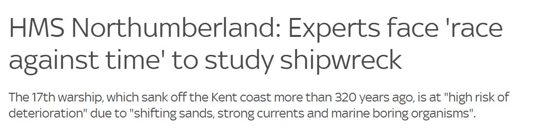
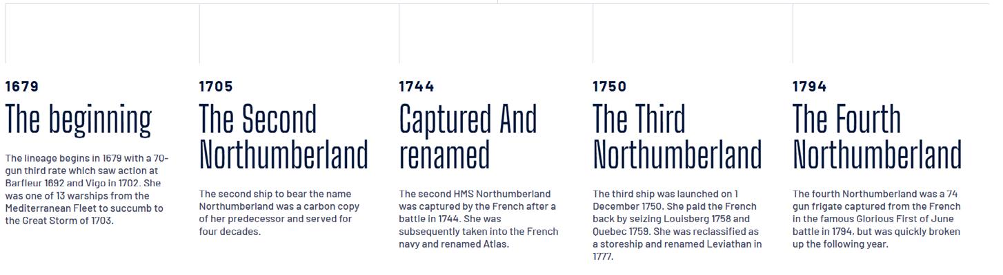
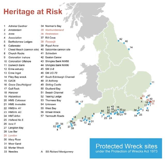
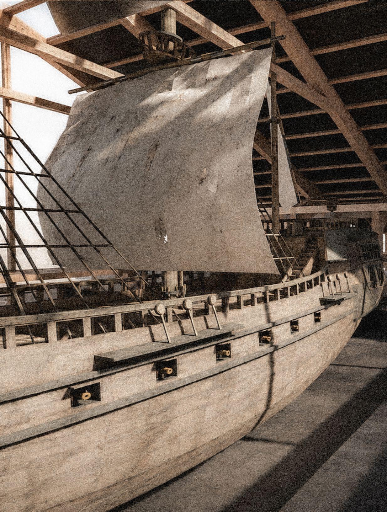
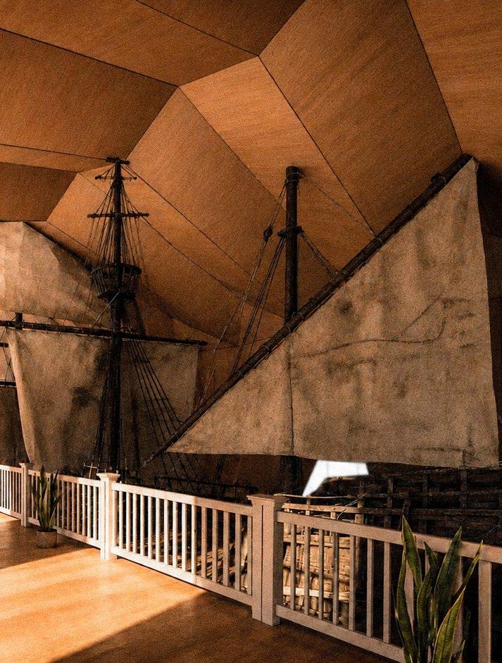
Currently identified as being at heritage risk, the Northumberland Ship will be integrated within a museum aspect of the programme to preserve a physical fragment of Britain’s maritime progressing history within an increasingly industrialised ferry corridor and 4th iteration of ship lineage, reinforcing the project’s broader ambition to embed cultural continuity.
SHOREHAM PORT HARBOUR
INTRODUCTION TO SITE
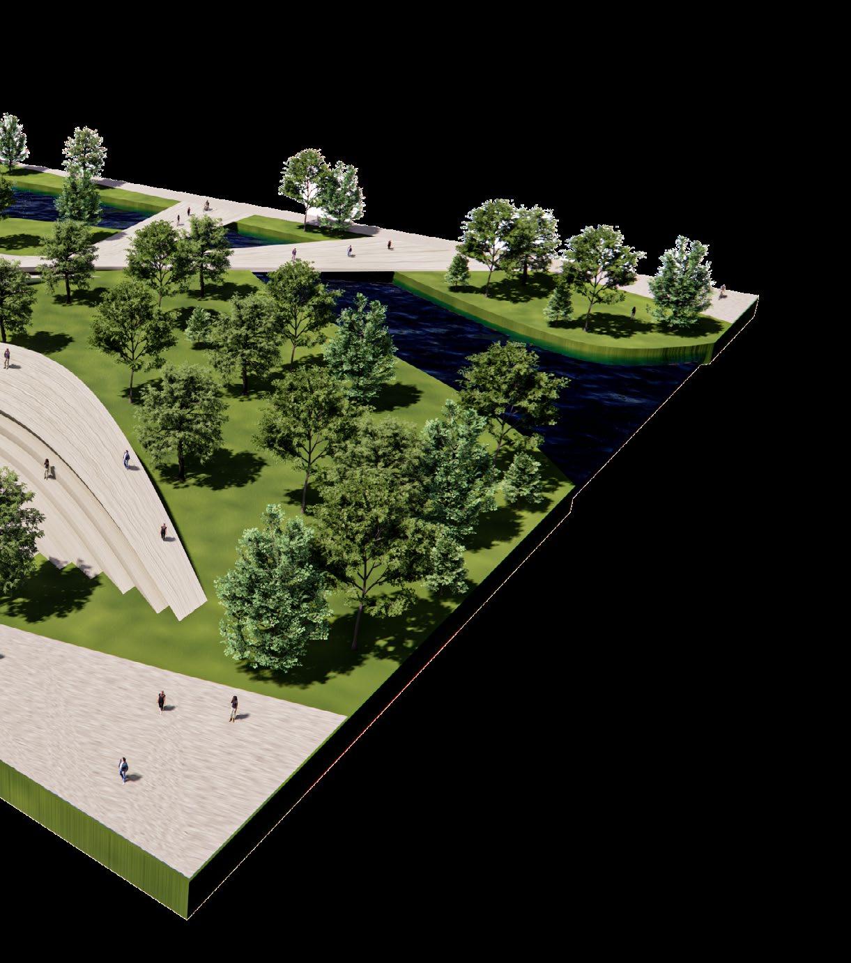
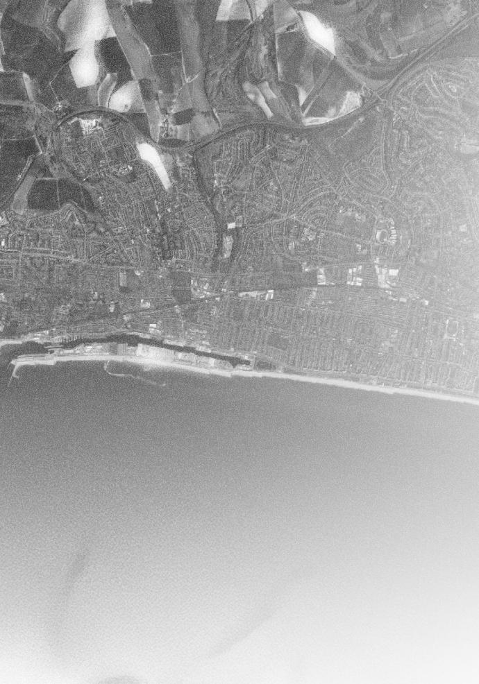
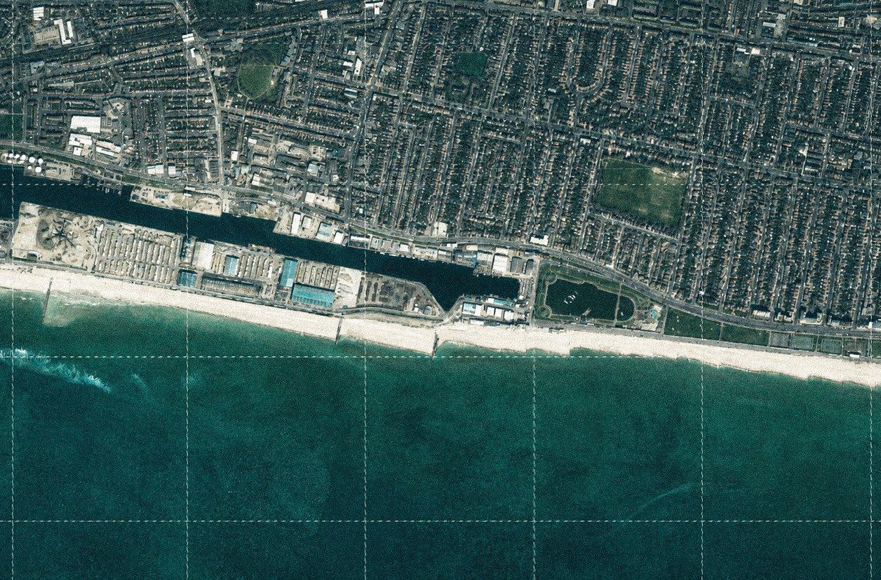
Positioned along the South Coast corridor, Shoreham Harbour operates as a threshold between industrial maritime infrastructure and public coastal condition.
SITE CONTEXT - REINTEGRATION
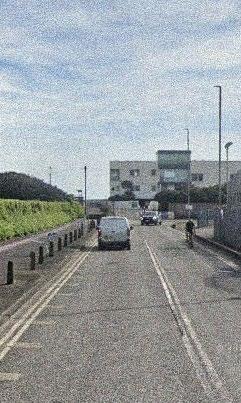
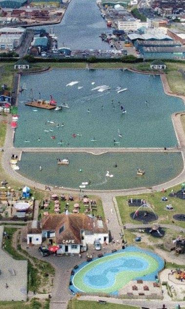
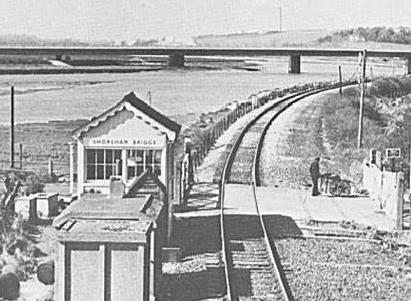
Existing site conditions reveal increasing fragmentation between operational harbour infrastructure, recreational waterfront activity and public coastal access across the wider harbour edge.
Parameters - Site Geology
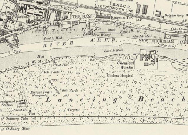
The site is classified as Made Ground (undivided), Holocene, indicating that the natural ground has been significantly modified through land reclamation and port-related activity. A high groundwater table is likely.
Parameters - Saltwater Impact
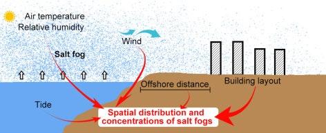
Salt water and marine moisture accelerate corrosion of metals and other facade materiality. Sea levels are rising (~4-8mm each year), increasing the risks of storm surge and coastal flooding. Materiality treatment would be required.
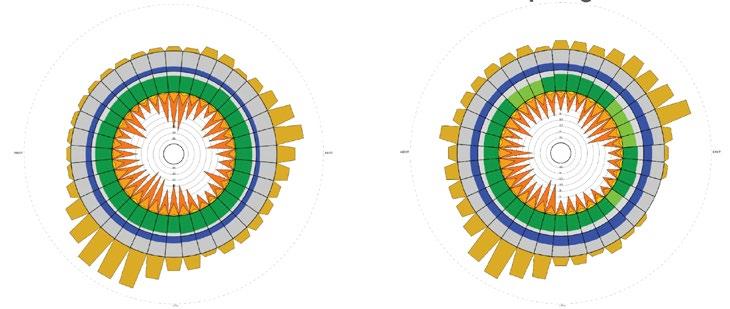
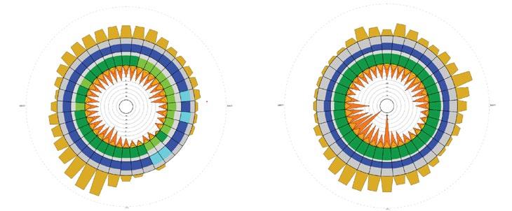
Climate analysis for Shoreham shows a mild coastal environment rainfall and relatively high humidity throughout the year. such as natural ventilation and maximising daylight, while hydrology.
Precipitation - Rainfall Averages
Annual Humidity + Cloud Coverages Wind Analysis
Long periods of wind from South West with occasional winds from the East; Little to no wind from North West 0-22 degrees
All year round is averaging over 70%
4m/s from South West; 3m/s from all other directions
Spikes of 14m/s and 18m/s from all other directions; Fewer spikes from South East
Psychrometric Chart Analysis + Preliminary Ideas
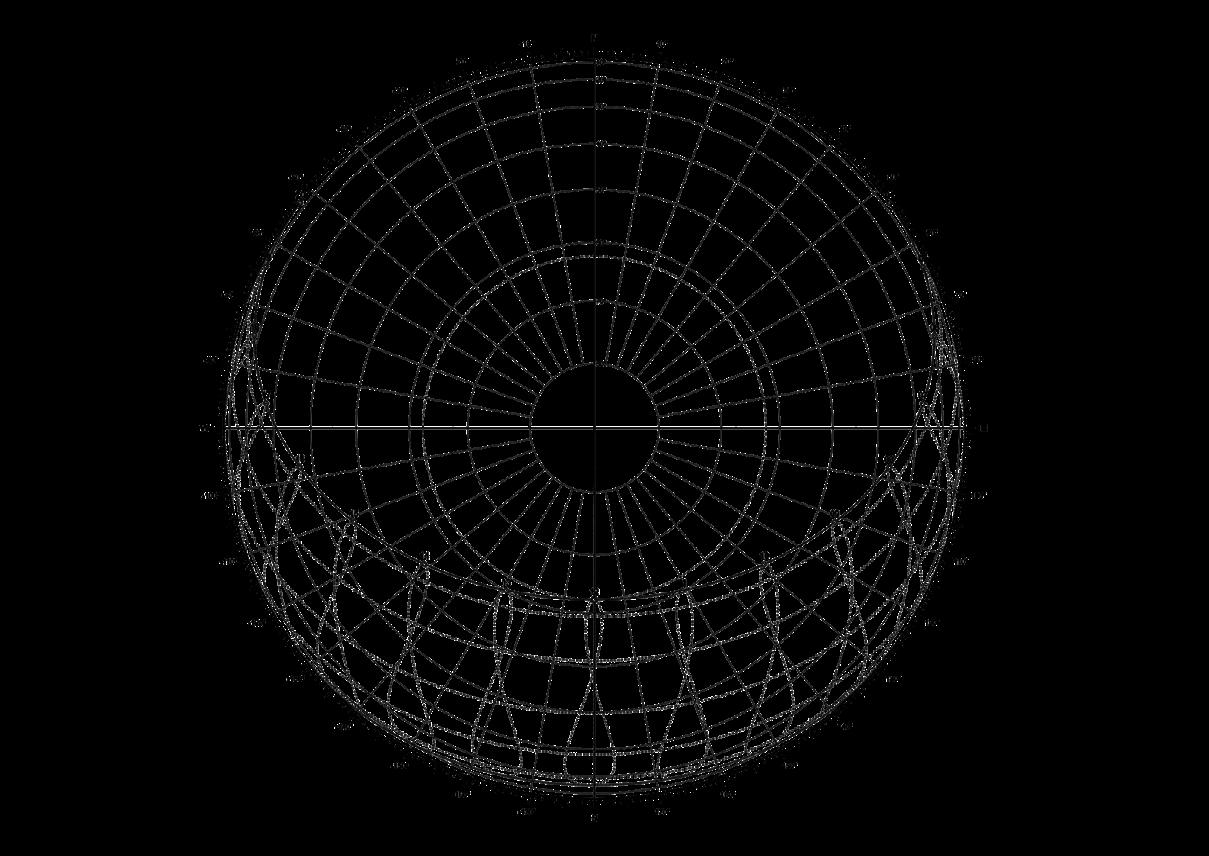
This graph identifies the effectiveness of design strategies.
environment with moderate temperatures, consistent year. These conditions support passive design strategies while requiring effective drainage and efficient use of hydrology.
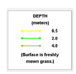
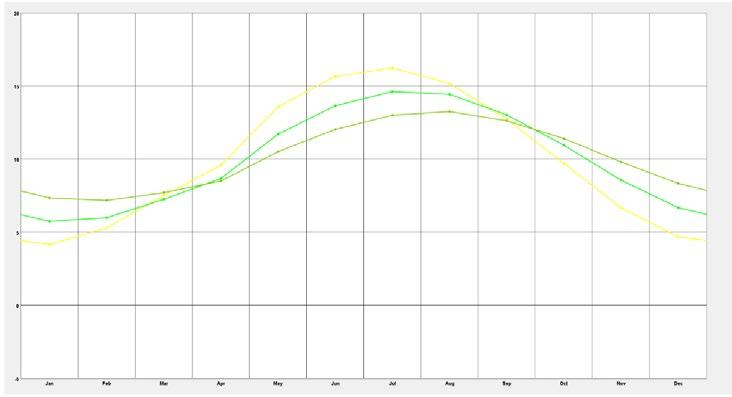
Ground Temperature Differentiation
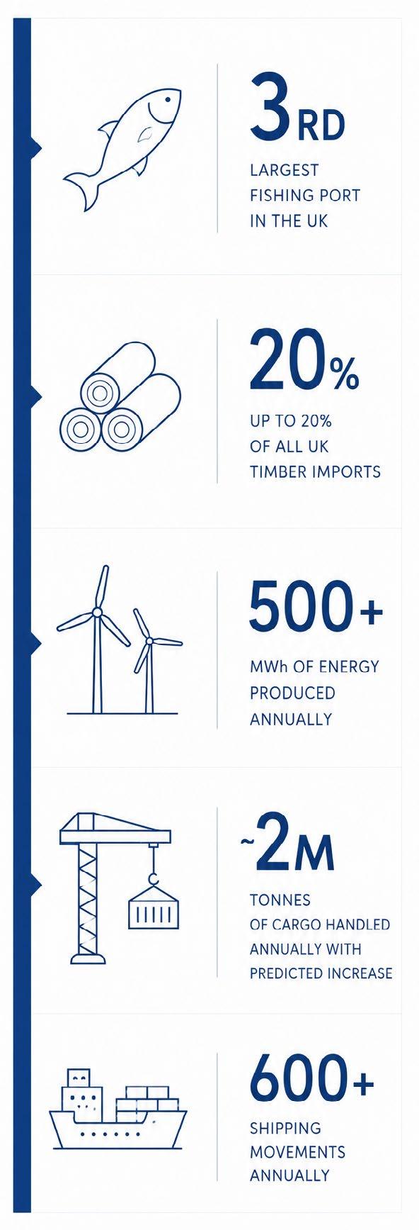
Shoreham’s established role in trade, logistics and material exhchange provides the foundation for future ferry integration.
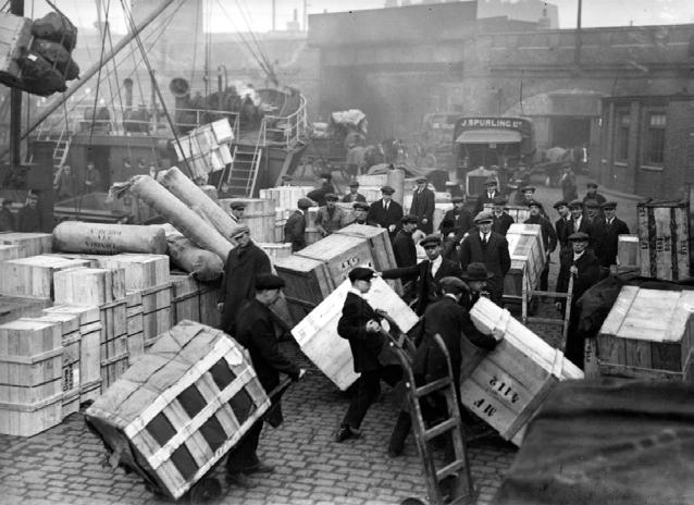
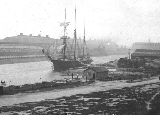
Shoreham harbour developed through the movement as a critical point of exchange between maritime and pressures associated with freight logistics, growing industries the waterfront
CURRENT UTILISATION
movement of materials, labour and goods, establishing its role and terrestrial infrastructure. Contemporary operational industries and recreation have increasingly fragmented waterfront condition.
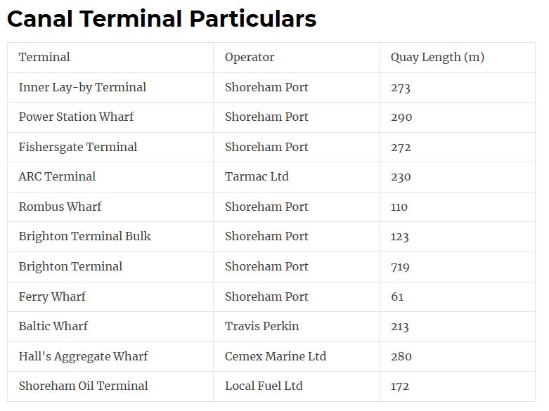
Vessel movement analysis mapped existing freight circulation, across the inner harbour, revealing the spatial pressures constrained canal
Cargo/Freight Dimensions
Circa. 103m
Passenger Ferry Dimensions
Circa. 41m
Corresponds to turning circle radius required
DIMENSIONS + ROUTE
circulation, docking behaviour and turning requirements pressures imposed by future ferry integration within the canal condition.
CORE 1
TERMINAL SNOITAREPO
• PASSENGER FERRY TERMINAL
• TICKETING, SECURITY
• WAITING LOUNGE
• EMBARKATION
FERRY TERMINAL PLANNING AND LOGISTICS
CORE 2
CULTURAL & CIVIC
• PRIMARY EXHIBITION
• PUBLIC GALLERY
• VIEWING DECK
• CAFE/RETAIL
INDUSTRIAL FACILITIES
CORE 3
CONSTRU C YTITLICAFNOIT
• BOAT CONSTRUCTION WORKSHOP
• STORAGE
• OFFICES
• DELIVERIES
PUBLIC CAR PARK
VEHICULAR ROUTE FOR CARGO
TO BEACH / BREAKWATER
ALTERNATIVE ACCESS
DEPARTURE
PUBLIC AMENITIES/ RESTAURANT
PASSENGER FERRY BOAT CONSTRUCTION FACILITY
The three programme cores are linked through a movement, public engagement and maritime industry, Shoreham Port industrial areas,
These diagrams highlighting demolished buildings and specific viewpoints, access points, existing civic and operational functions determine the programme placement
ROAD ENTRANCE
OVERALL SITE STRATEGY
shared circulation strategy, balancing passenger industry, while strengthening connections between areas, the harbour and the lagoon.
The artefact study informed the organisation of programme establish an early framework for subsequent
ARCHITECTURE
programme through the abstraction of a maritime form to subsequent design development.
SECTION 3
DESIGN DEVELOPMENT
Restaurant
Boat construction
Private access
Exhibition Space
Terminal operations
Public amenities
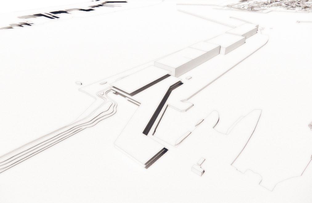
PLAN ITERATION 1 - FRAGMENT
Maritime trajectories and site geometries informed the testing programmatic and spatial frameworks to be iteration, the museum becomes
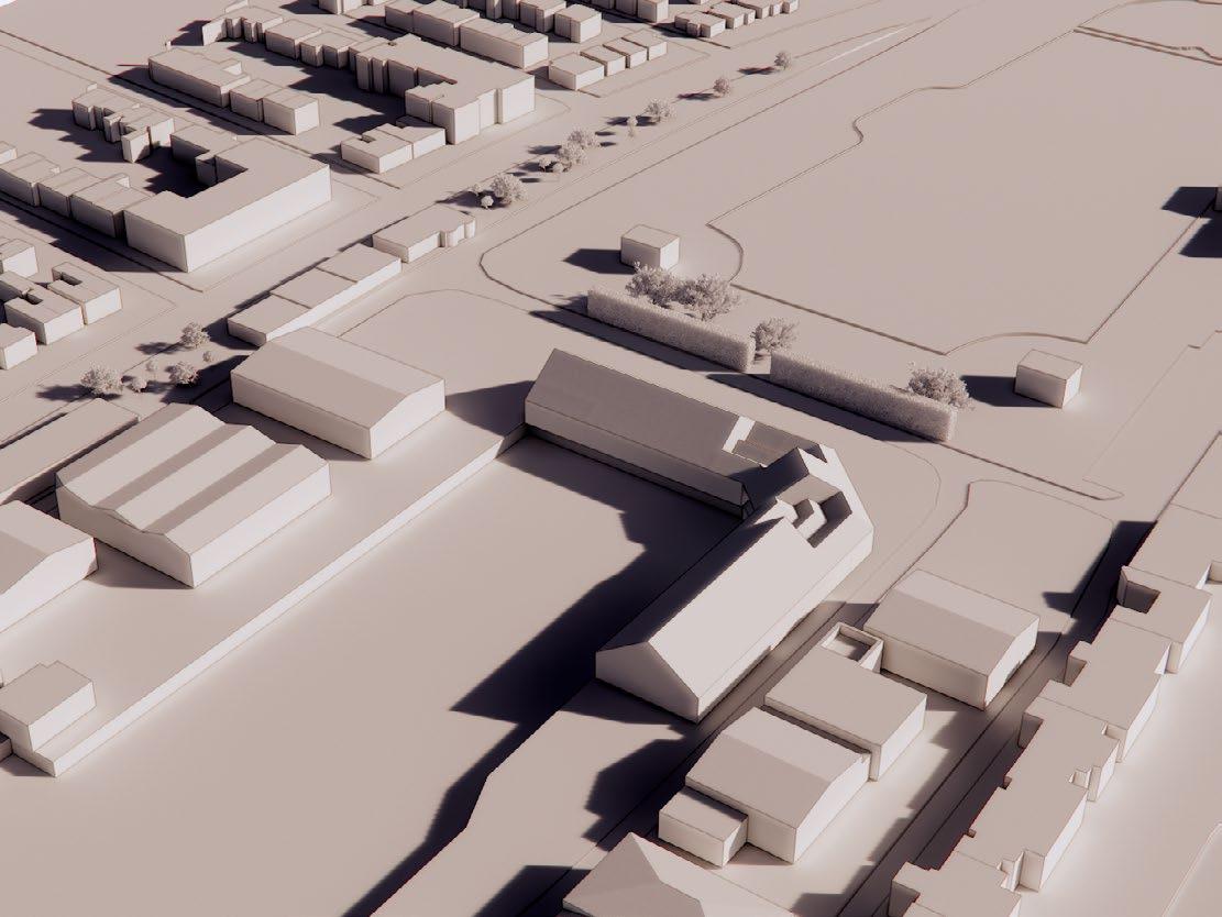
FRAGMENT FORMATION
the initial generation of architectural fragmentation, be carried forward throughout the proposal. In this becomes the central core.
Viewing deck
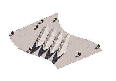
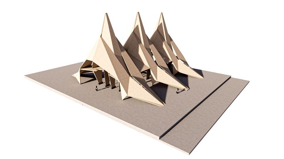
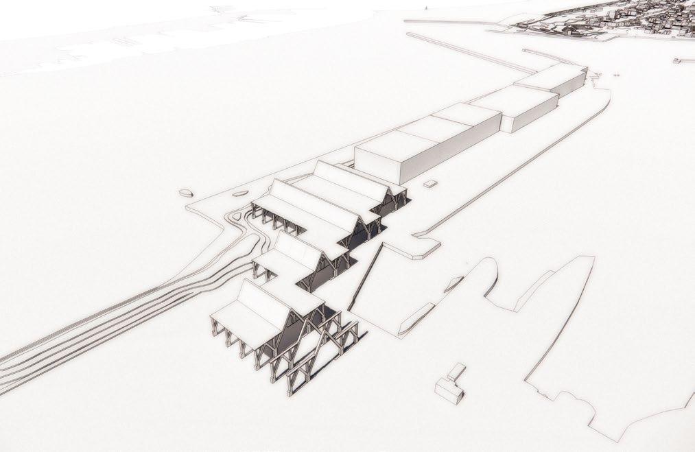
An early massing study explored the aggregation of architectural triple gables to convey themes of hierarchy, drawn
architectural fragments, employing single, double and drawn on research by Gare de Mons and cruck systems.
IMPORTED MATERIALS - EXISTING TIMBER HANDLING
LOCAL + SCANDINAVIAN MATERIALITY
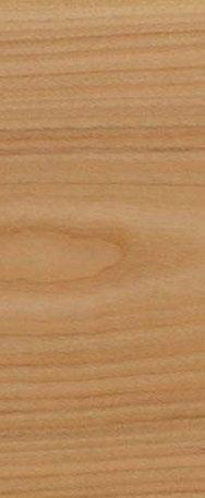
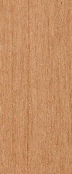
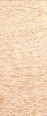
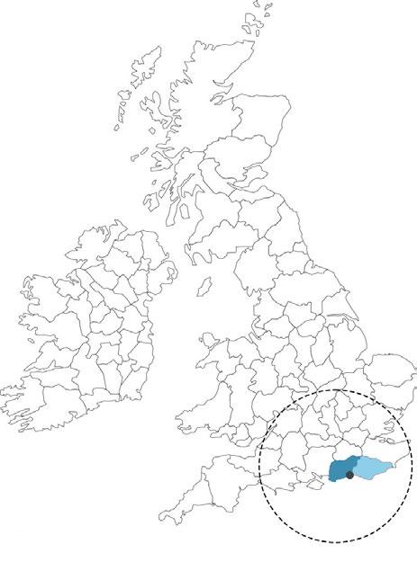
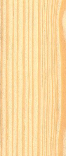
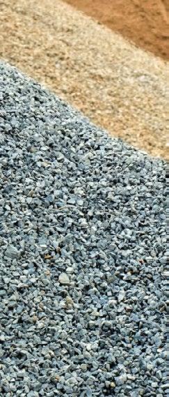
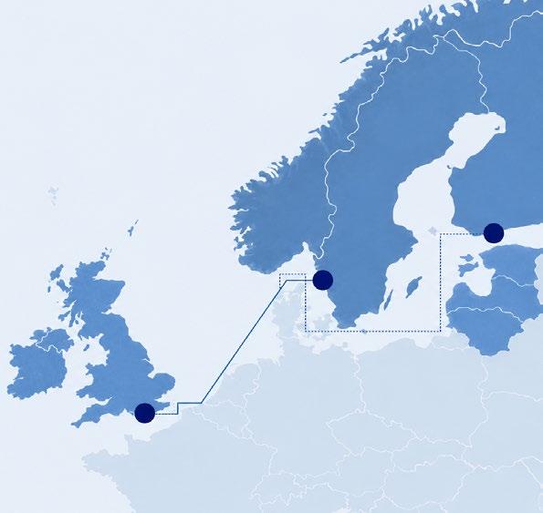
Local Sussex hardwood and Scandinavian timber were identified to establish a material palette informed by existing regional sourcing, Nordic construction traditions and maritime timber craft.
Chichester
Arun
Mid Sussex
Crawley Horsham
Worthing Adur
St Leonard’s Forest
Ebernoe Common
Upper Adur Valley
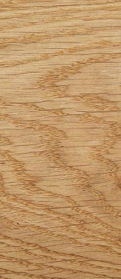
Sweet Chestnut Castanea Sativa Hardwood
Alder Alnus Glutinosa Hardwood
Birch Betula Pendula Hardwood
Oak Quercus Robur Hardwood
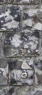
Flint Sicileous Stone
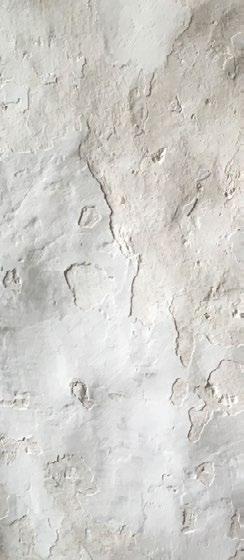
Clay + Chalk Plaster Alumino Silicate
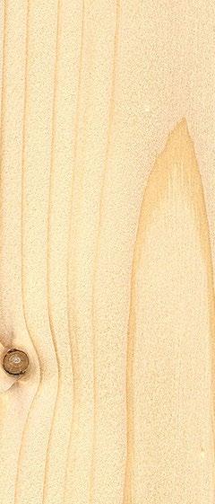
Norway Spruce Picea Abies Softwood
Scots Pine Pinus Sylvestris Softwood
Aggregates Sand, Gravel Shoreham, UK
Gothenburg, Sweden
Kotka, Finland
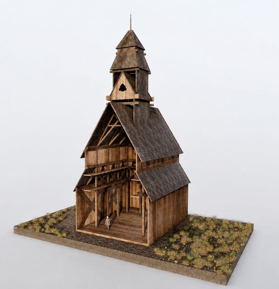
STAVE CHURCH ‘NAVIS’ + CRUCK ETYMOLOGY
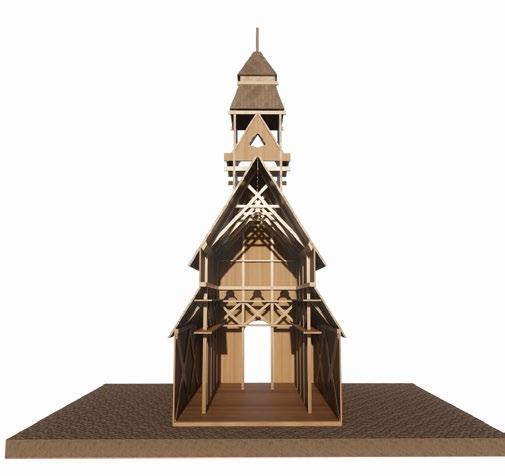
The stave church is analysed through its exposed timber frame, layered hierarchy and ‘navis’ symbolism, where ship-like structural ribs organise procession and enclosure through a central timber volume. These principles inform the development of a contemporary cruck-like system constructed through double layered CLT systems while retaining the ceremonial spatial sequence of historical maritime architecture.
STRUCTURAL AND FORMAL
Research into traditional cruck construction informed single and triple gables volumes established principles into the later tectonic development - highlighting an design, much like the juxtaposition of industrial
FORMAL DEVELOPMENT
an early structural framework, while the articulation of of hierarchy and enclosure that were carried forward an abstraction of the traditional cruck into a modern industrial to contemporary operations.
ARTEFACT
The presrved vessel forms the spatial focus of the museum, artefact within a large-span
museum, allowing visitors to engage directly with the
exhibition environment.
The gabled structural framework establishes a hierarchy between ship construction and form - later to be abstracted keeping focus on the concept
EXPRESSION
hierarchy of volumes, expressing the direct relationship abstracted utilising modern advances in construction yet concept of the folding roof form.
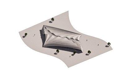
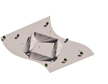
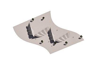
FURTHER MASSING REFINEMENT -
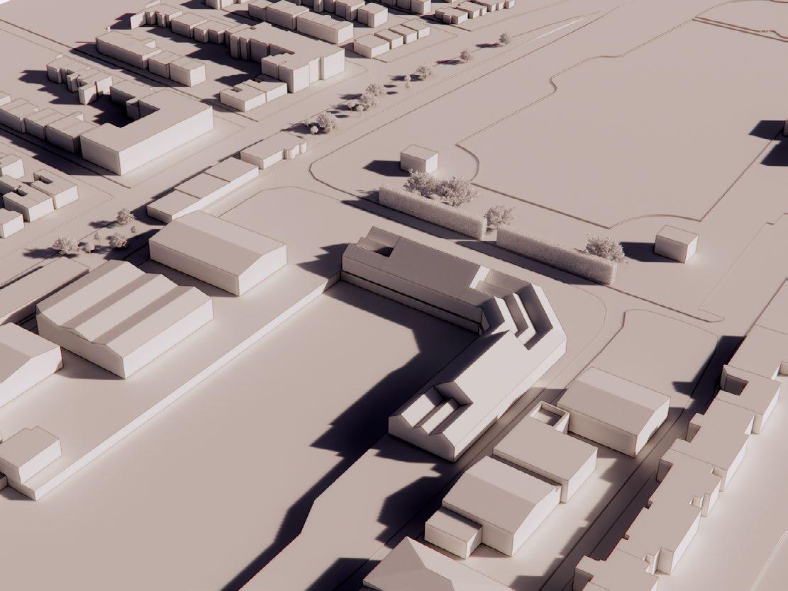
Successive massing studies tested the relationship highlighting the organisational framework
ROOFING SURFACE ABSTRACTION
relationship between site constraints and gabled volumes, framework carried forward into the final proposal
Restaurant
Exhibition Space
Primary viewpoint
Public amenities
Terminal operations
Boat construction
PLAN ITERATION 2 - PROGRAMMATIC
The distribution of programme tested relationships between informing the organisational principles developed later. museum, enabling the museum to act as a cultural activities.
PROGRAMMATIC DISTRIBUTION
between operational, educational and cultural functions, later. The primary viewpoint is located adjacent to the buffer between industrial and recreational maritime activities.
FRAGMENT 1
SHOREHAM PORT TYPICAL UNIT
FRAGMENT 2
THEATRE VIDY-LAUSANNE
SITE CONTEXTUAL RHYTHM
LINEAR REPETITION
KEY DESIGN DRIVERS -
ABSTRACTING
Maritime trajectories and site geometries informed the testing programmatic and spatial frameworks to
FRAGMENT 3 FRAGMENT 4
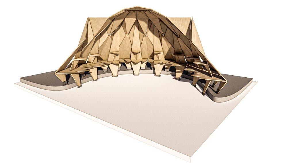
RADIAL ENCLOSURE
ABSTRACTING THE FORM
the initial generation of architectural fragmentation, to be carried forward throughout the proposal.
HIERARCHIAL ORDER
SOM CADET CHAPEL DOMAINE DE BAYSSAN
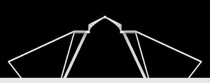
This early-stage design constraints study is exploratory of the 60 degree limit for CNC production technology to efficiently manufacture wood-wood connections.
PLANAR MASSING + STRUCTURAL RIGIDITY DEVELOPMENT
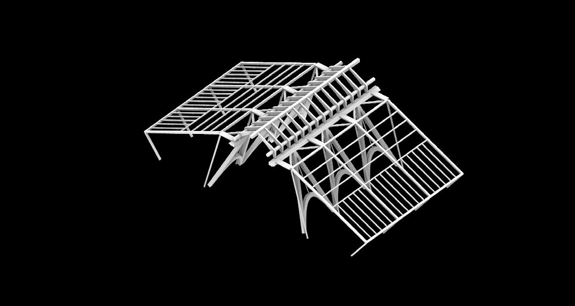
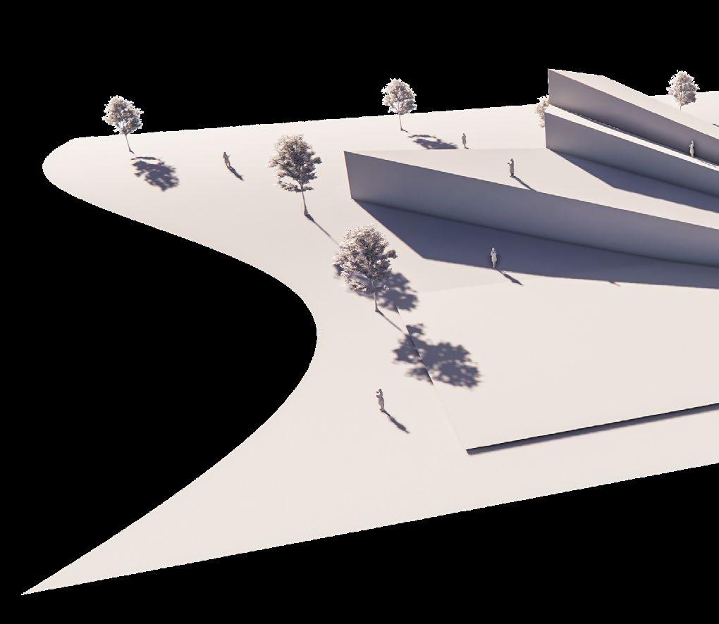
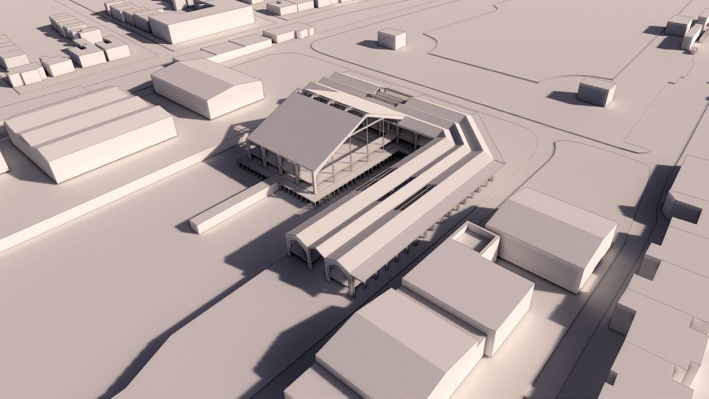
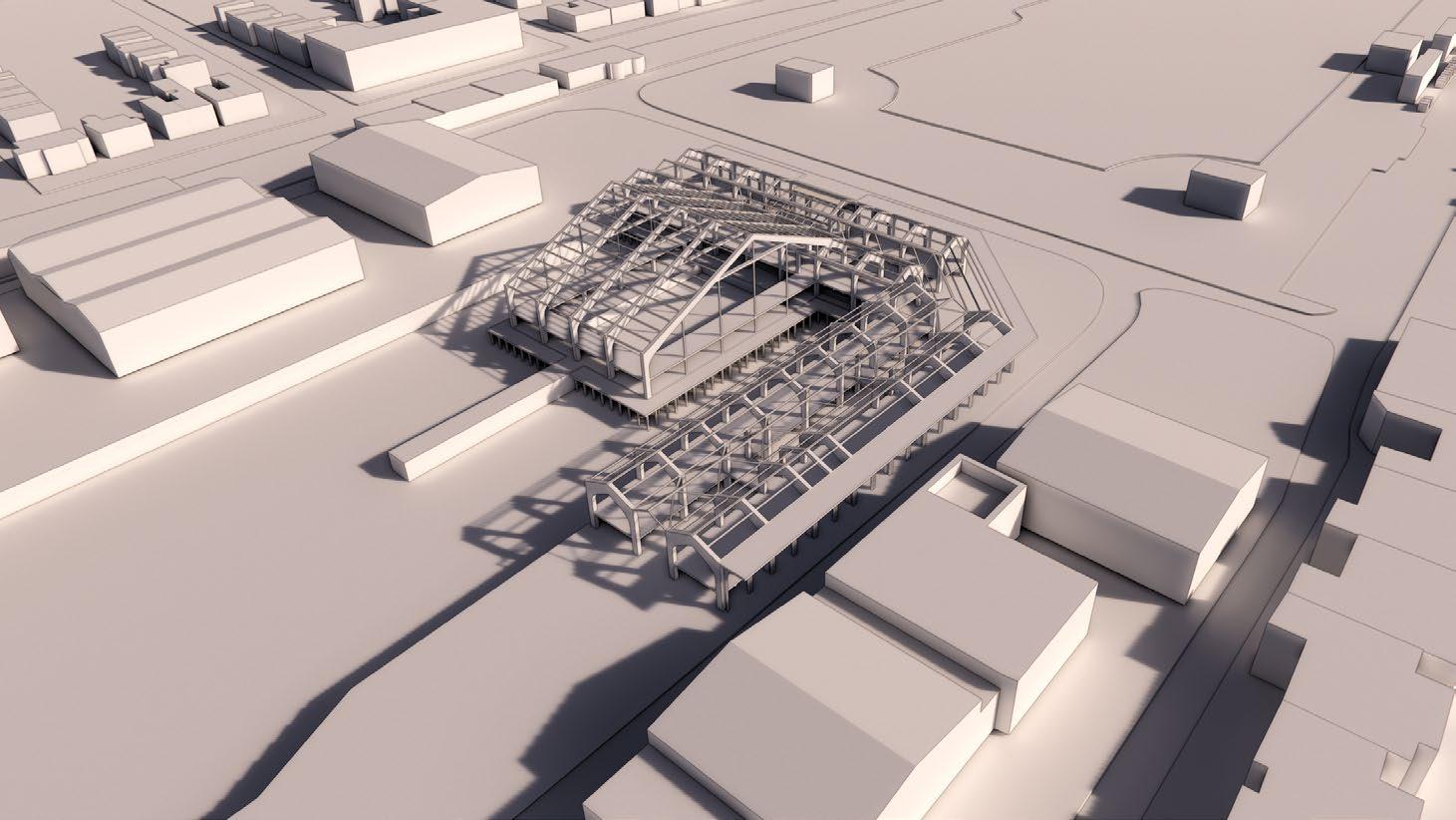
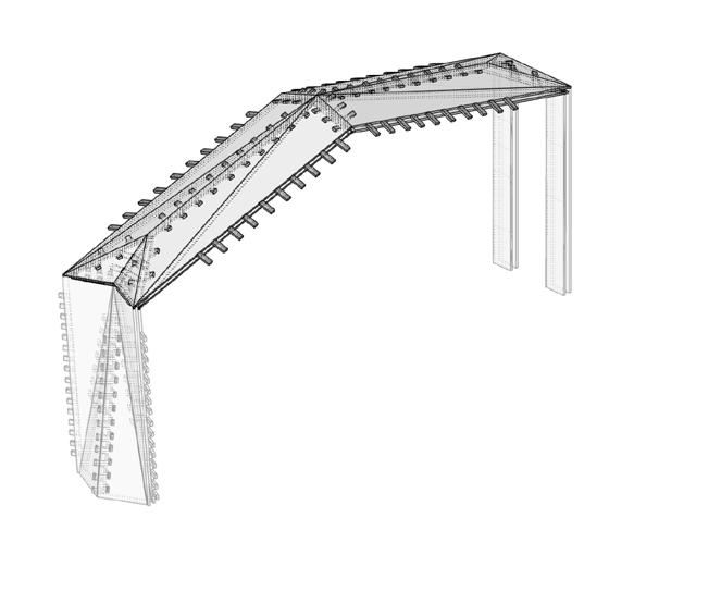
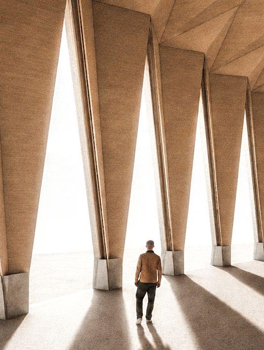
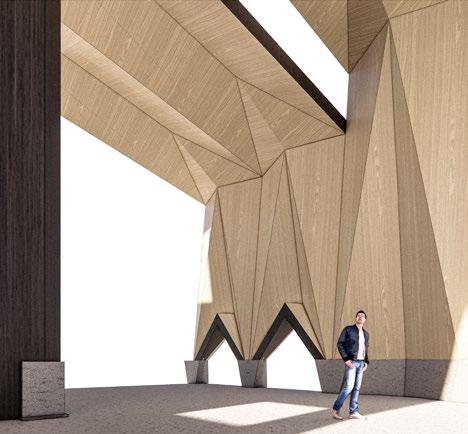
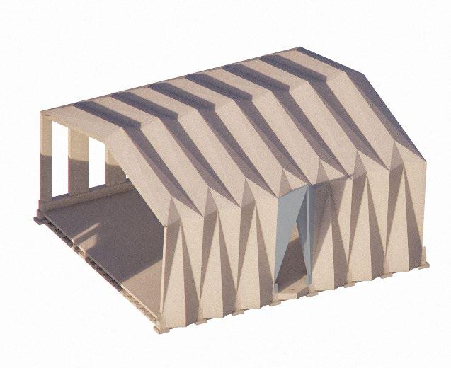
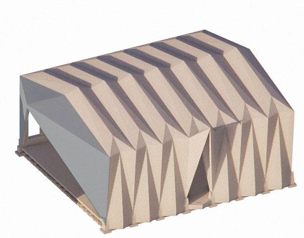
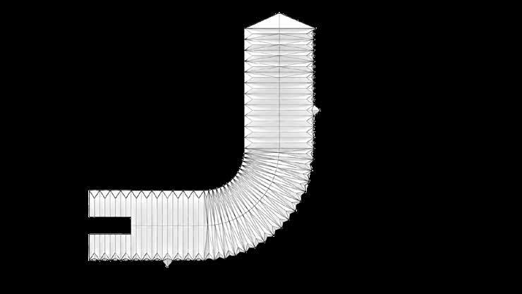
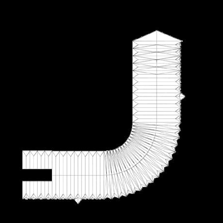
Folded planar elements reinterpret earlier gabled forms, generating enclosure, structure and spatial hierarchy. This includes development from Fragments 1 + 2.
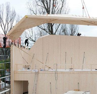
Folded CLT plates are CNC milled off-site using digitally fabricated cutting paths to produce interlocking timber connections. Prefabricated structure is lifted directly from fabrication bed through crane handling before transportation and on-site assembly.
CNC MILLING + TRADITIONAL GABLE FURTHER DEVELOPMENT
The proposal separates permanent ground-contacting elements from the primary timber superstructure utilising concrete casting to seamlessly integrate the design framing.
This project innovates through the integration of prefabricated folded CLT systems with existing maritime logistics, creating a direct link between material supply chains and architectural form.
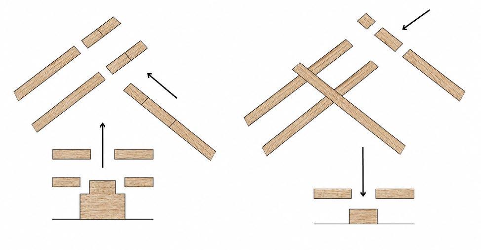
Assembly/Disassembly Principle
Designing for Disassembly
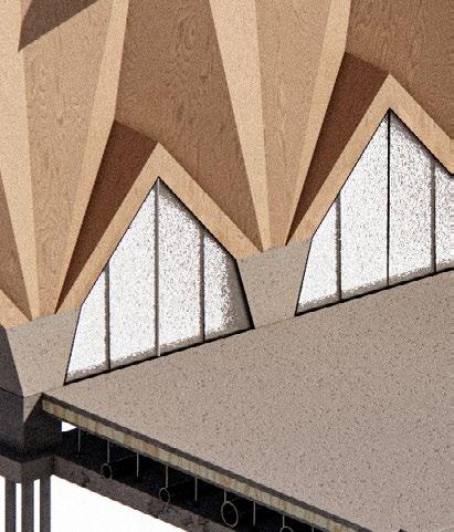
Chamfered interlocking joints improve assembly tolerance. Cellulose is placed between double layered CLT plates to provide acoustic and thermal performance
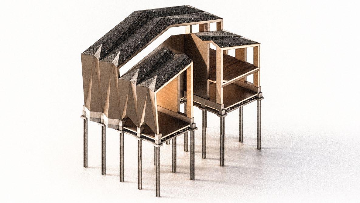
PRIMARY STRUCTURE CONSTRUCTION METHOD Primary Folded CLT Plate Formation Vertical Support Connection Installation
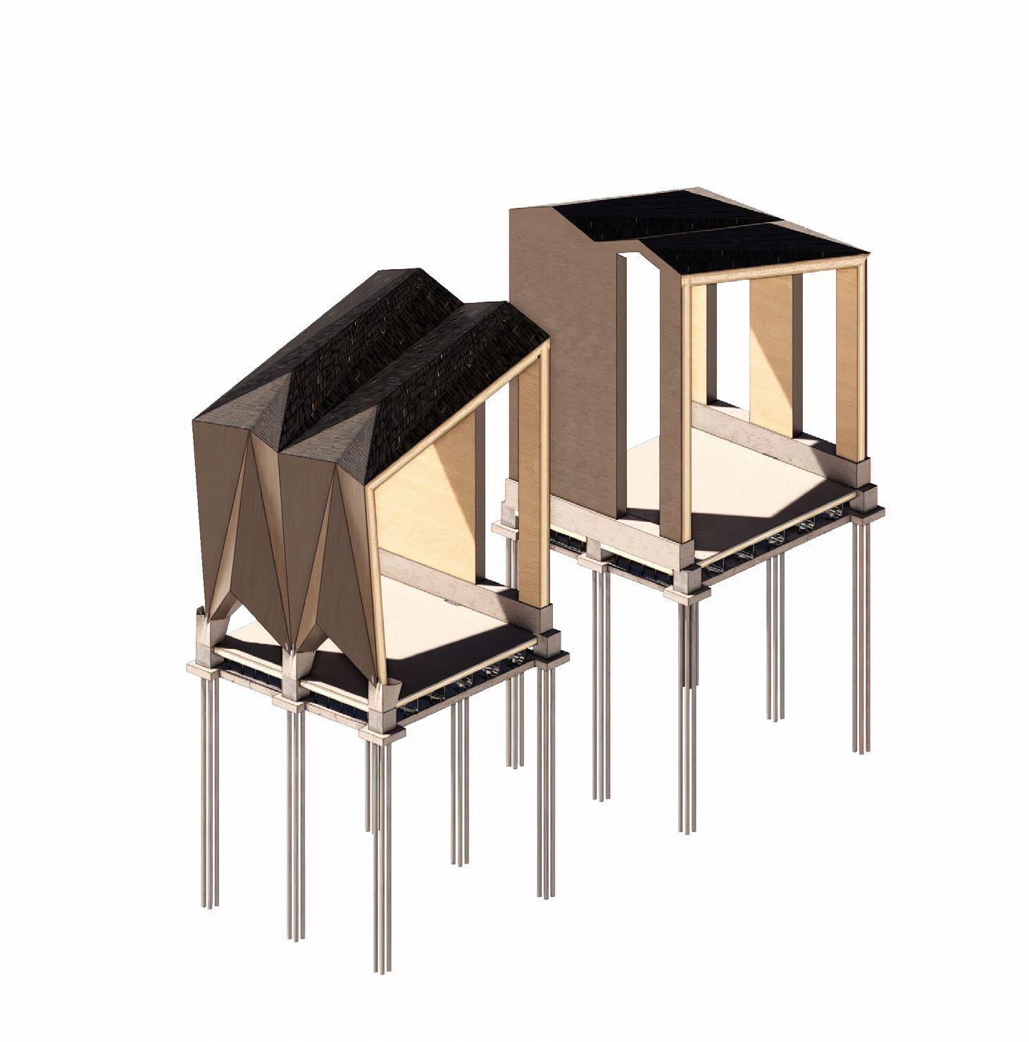
LINEAR GABLE MODULE
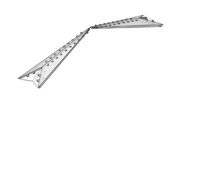
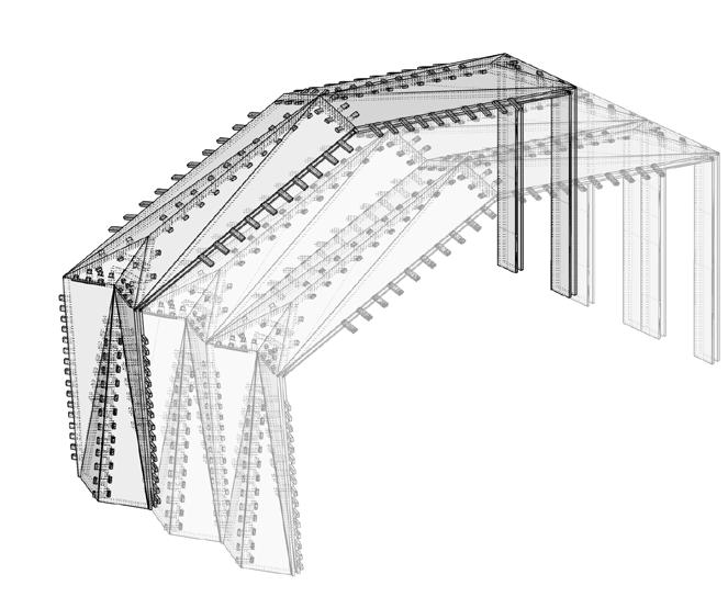
Sequential folding and assembly transforms a planar module. Double layered interlocking elements
planar element into a self-supporting gabled structural elements enable a tectonic system to be replicated.
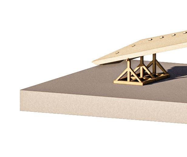
The construction method utilises reusable supports to create regular modules, able to be adapted for height and width. This would be a sustainable construction method whereby modules will be prefabricated and constructed on site to reduce site traffic and exposure to salt winds.
Excess of nodes to be sanded post construction for cladding purposes.
SEQUENTIAL PHYSICAL TESTING
Physical model testing evaluated the structural limitations and integrity, determining node placement for connection logic, load distribution and the potential for modular adaptability.
PHYSICAL FORM TESTING
This overall form supports the idea of structural stiffness for the linear module, placing cellulose insulation between the CLT panels to ensure regulation for thermal and acoustic properties.
Abstracting the triple gable form, independent modules occupiable
GABLE SEPARATION
modules explore the creation of external procession and
space.
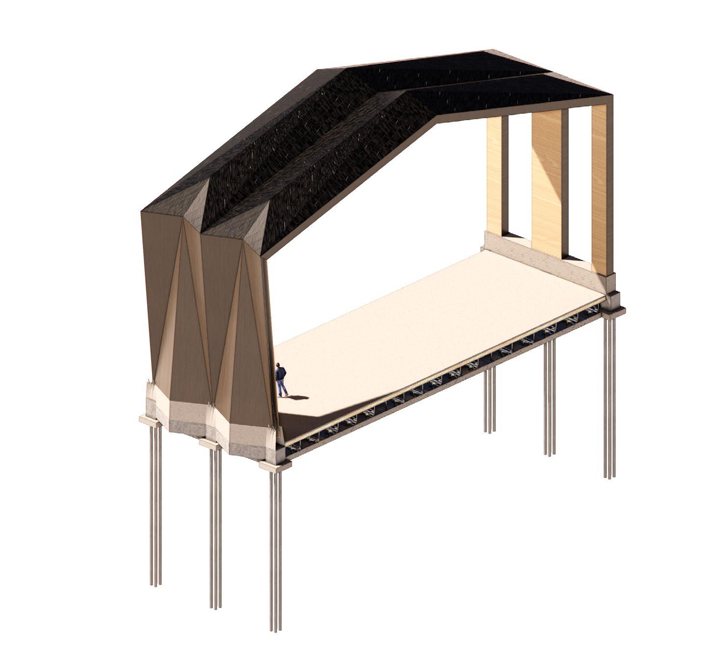
FRAGMENT 2 - MODULAR
Removing intermediate volumes created a flexible accommodate larger
MODULAR OPEN SPACE
flexible open bay, testing how the tectonic system could uninterrupted spaces.
Consolidating programme around a perimeter condition circulation, operational management
condition highlighted a clearer relationship between management and public occupation.
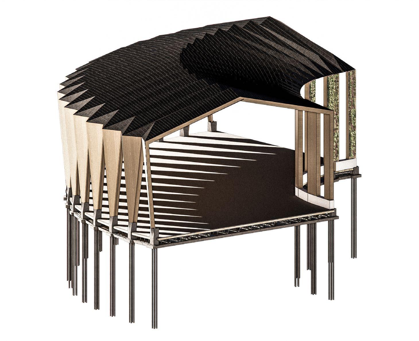
FRAGMENT 3 - RADIAL
Consolidating programme around a perimeter condition circulation, operational management
condition highlighted a clearer relationship between management and public occupation.
FRAGMENT
Individual fragment studies are consolidated into a coherent enclosure and
Energy efficiency and temperature thermal regulation with U-value of ~ 0.7W/M2K
Vertical hierarchy with stepped structural rhythm. This adaptation allows controlled daylighting and highlighting programme hierarchy for circulation Stave Church Tectonic Principles
Steep roofing allows for removal of rainfall quickly to reduce water retention and timber decay.
✓
✓
Charred Timber Benefits
Lower embodied carbon compared to conventional external cladding systems through sustainably sourced Scandinavian softwood
Maritime trade accessibility between Scandinavia and Shoreham supports efficient regional sourcing and material transportation
✓
Increased durability within exposed coastal and high-moisture environments
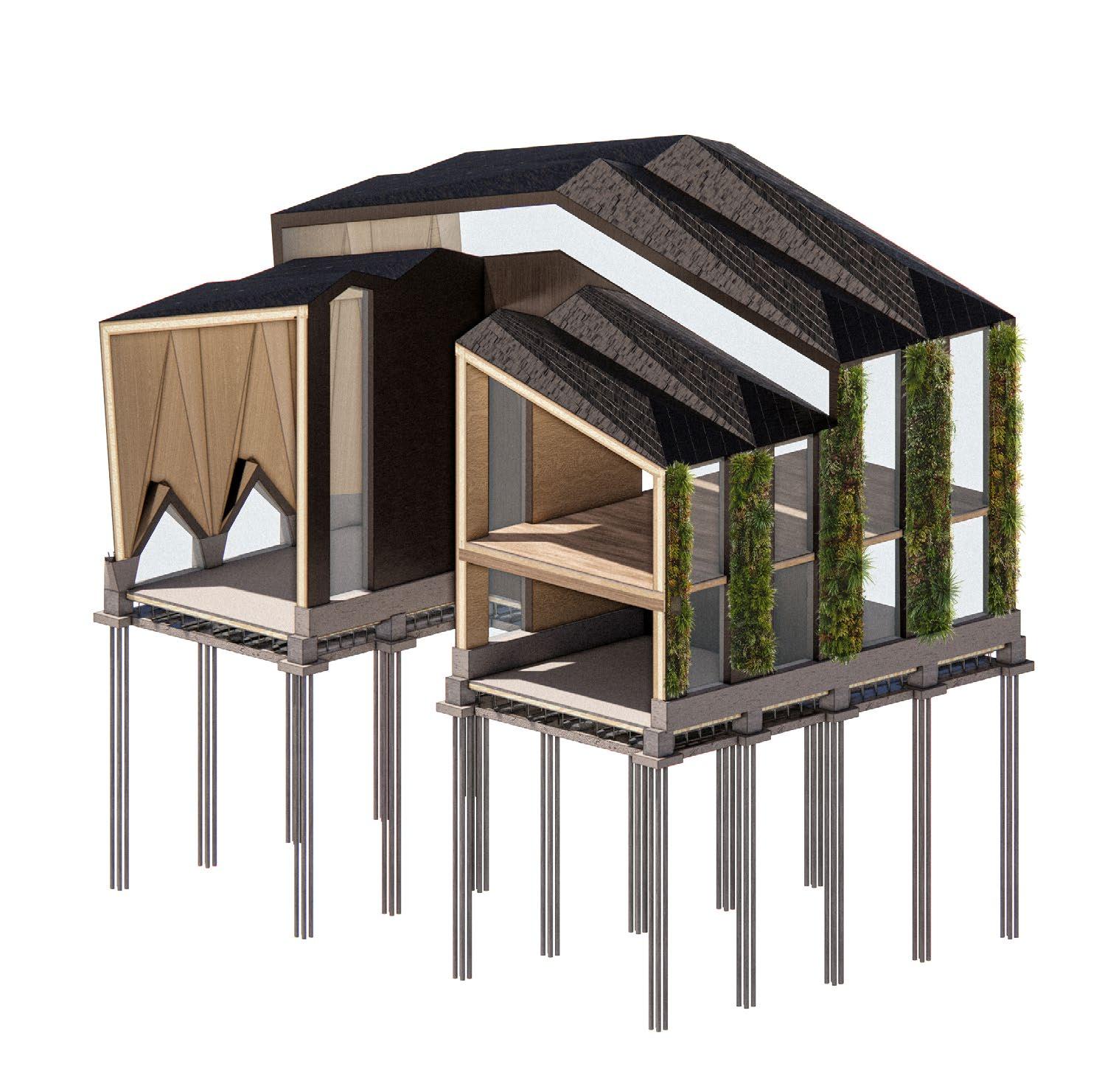
Structural Build-up (Tectonic Adaptation)
Glulam support column 210mm
Cellulose insulation (between) 210mm
Timber floor finish 25mm
Acoustic/service layer 50mm
CLT floor slab 200mm
Solid timber block
Glulam beam 400mm
Secondary vapour control barrier
Solid timber block
Internal structural CLT layer 100mm
Air cavity with timber battens 40mm
Vapour control barrier
Charred timber cladding 30mm
Folded CLT geometry alone provides insufficient rigidity along the harbour edge
✓ Supplementary glulam columns reinforce structural stability within the envelope
✓
✓ Concealed structural supports maintain tectonic continuity within the facade system X
Integrated floor beams distribute strutural loading across the folded form
STRUCTURAL
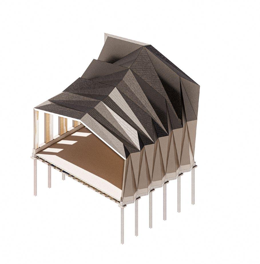
The proposed assembly integrates CLT construction, charred to create a durable coastal envelope. Structural and folded tectonic form, ensuring continuity
charred timber cladding and high-performance glazing and environmental strategies are embedded within the
concept and construction.
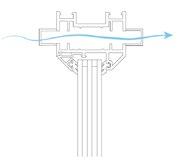
Triple glazed custom window
Ground floor build up
Pile foundations for reclaimed ground
Timber finish first floor build up
Green wall build up*
UV protective glazing*
Double layered CLT primary structure
Charred timber cladding
Glazing Solar roof
HeucheraImproves biodiversity through dense evergreen foliage and seasonal variation
Carex GrassesEnhances biodiversity and wind resilience within exposed coastal conditions
SedumProvides drought resistance and low-maintenance ecological coverage
Coastal FernsSupports shaded habitat creation and moisture retention across the facade.
Soft landscaping provides BNG and social impact through external masterplanning means.
Lavender -
Pollinator-friendly planting thriving in dry, sun exposed coastal conditions
Festuca GlaucaSalt-tolerant ornamental grass improving biodiversity and visual texture across waterfront
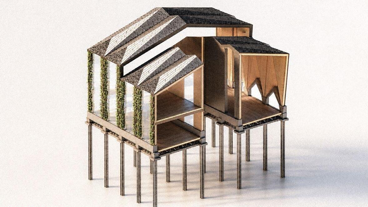
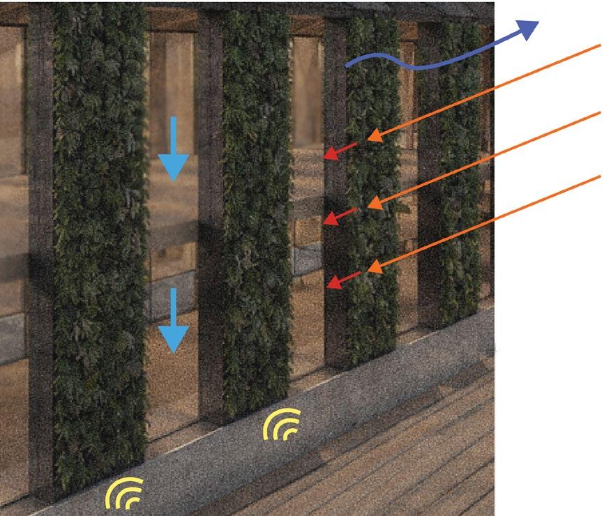
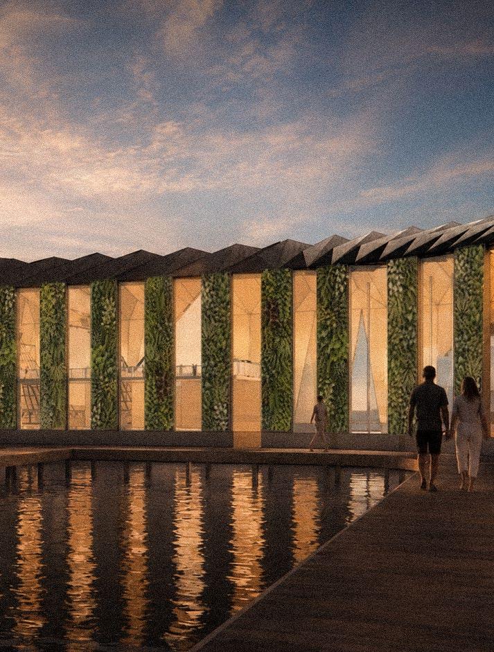
The green wall system integrates salt-tolerant coastal planting species to improve biodiversity, passive cooling and environmental resilience within the exposed harbour environment.
GREEN LIVING WALLS + PASSIVE COOLING
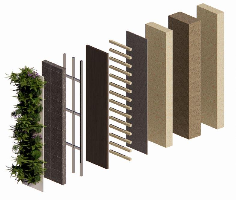
CLT structure
Cellulose
CLT structure
Vapour Barrier
Air cavity, timber battens
Charred timber cladding (rot resistant)
Steel fixing system with drip irrigation system
Modular planting tray
Coastal planting green wall system
Provides habitat for pollinators and insects
Provides evapotranspiration to passively cool the building
GREEN WALLING
Complimentary Materiality - Charred timber is naturally resistant to decay and rot which makes it an ideal substrate for supporting a green wall system that requires iriigation and ensuring longevity within the design. Glulam columns will be utilised to ensure structural integrity within the CLT build-up.
water
through
Green wall systems are primarily integrated along the museum and terminal facades to reduce solar heat gain in open, public spaces in the afternoons when these programmed spaces are predominantly used.
THERMAL
Evapotranspiration (passive cooling)
Solar radiation
Transmitted radiation
Internal cooling load
Vegetation and planting depth provide supplementary acoustic absorption
PROPERTIES / STRATEGIES
Glazing and green walling provide thermal insulation alongside cellulose insulation between the double layered CLT panels. Heating and cooling strategies are in place through radiant floor heating beneath the floor within a layer of screed.
Warm
circulates
the underfloor pipes. Heat is transferred upwards through the slab to warm the space
Cool water circulates to enable heat from the area to be absorbed into the slab and removed. Hot air exits via trickle vents and openings
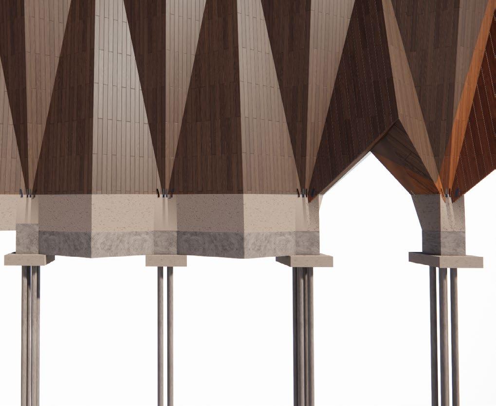
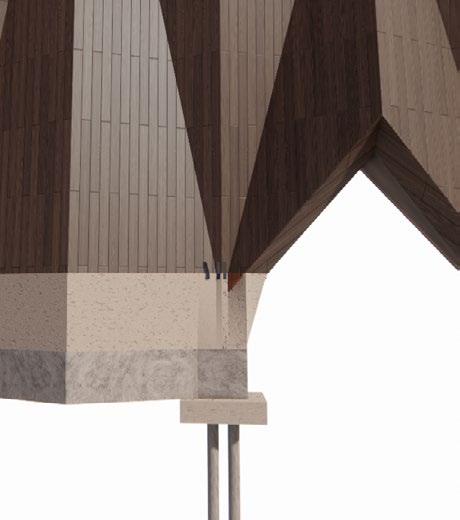
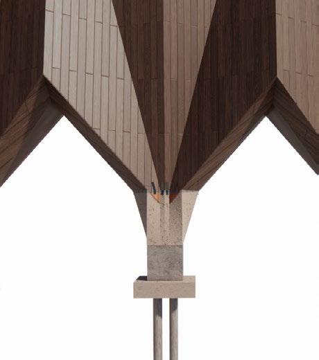
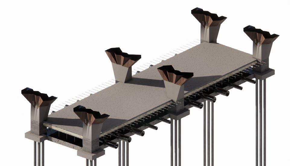
The foundation strategy uses reinforced concrete pile footings to transfer loads from the folded timber structure into stable ground conditions while ensuring the timber would not be exposed to marine floods, preventing any further risk of rot.
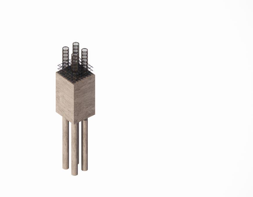
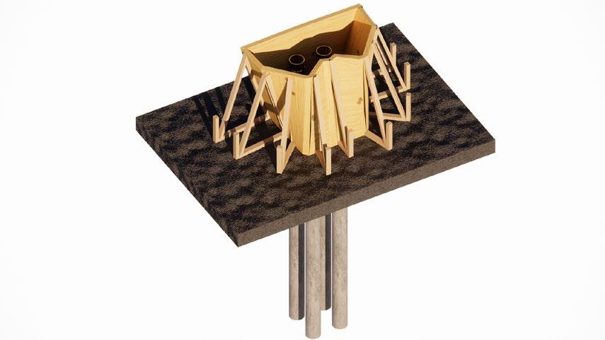
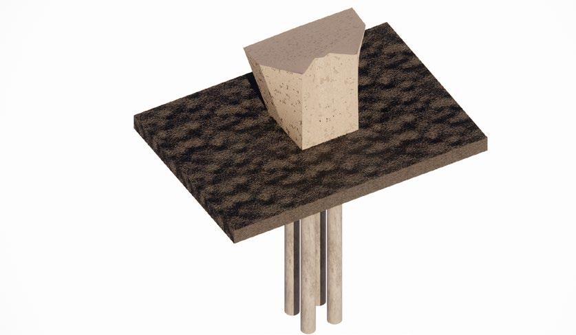
This footing system is constructed through stages pile installation, temporary timber formwork assembly and cast in-situ concrete caps to create stable connections between the primary structural CLT frame and pile foundations.
Custom cast in-situ concrete footings were formed using unique folded column geometries. The system provides piled foundations, responding to the
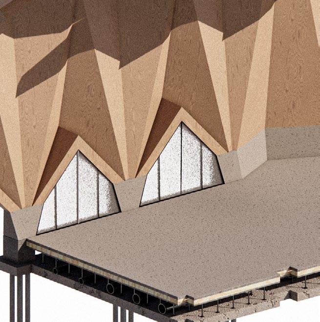
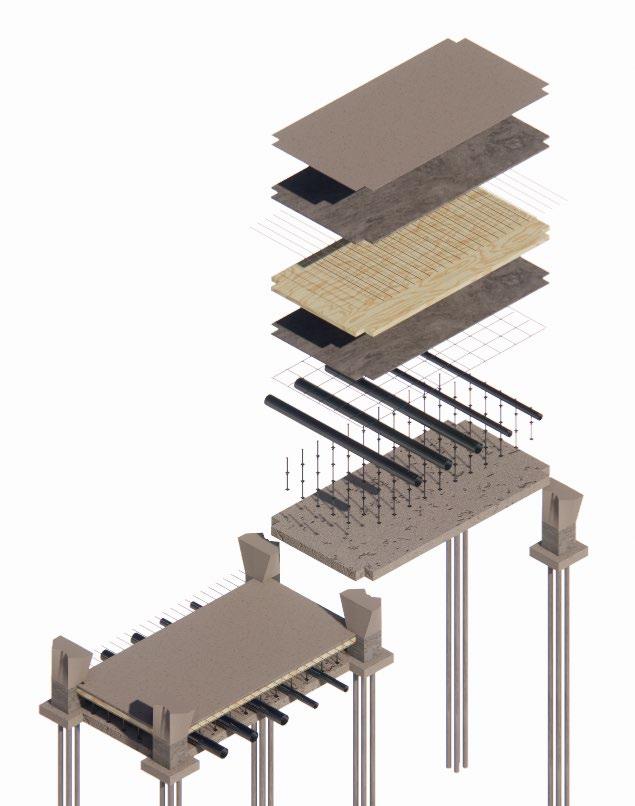
Concrete floor finish (75% GGBS)
Screed for radiant floor heating system
Radiant floor heating pipes
Mineral wool insulation (thermal and acoustic)
Cement floor panels within steel supports
Reinforcement steel support system
Services (notably water, gas electricity, drainage + tele-communications)
Raised floor support system (600x600 grid)
Structural concrete slab - pre cast
FOOTING TO PRIMARY STRUCTURE BUILD UP
CLT primary structure attached through steel cleats and anchor joints
Column footing (overground) cast in-situ concrete
Column footing (underground) - concrete
Concrete pile cap
Concrete pile foundation
using temporary timber formwork to accommodate the provides a clear load path between the CLT structure and the reclaimed land of the waterfront.
Restaurant
Exhibition Space
Primary viewpoint
Terminal operations
Public amenities
Boat construction
Consolidating programme around a perimeter condition circulation, operational management
OPERATIONAL CONSOLIDATION
condition highlighted a clearer relationship between management and public occupation.
Museum + dock primary viewpoint
Primary entrance and viewpoint modular differentiation
SECTION ITERATION 3 - OPERATIONAL
Consolidating programme around a perimeter condition circulation, operational management
Module ending condition / sheltering and entrance
OPERATIONAL CONSOLIDATION
condition highlighted a clearer relationship between management and public occupation.
Height variation establishes a hierarchy of programme, through elevated volumes while operational spaces remain strengthens visibility, orientation and
programme, with public and cultural functions expressed remain compressed and secondary. This differentiation public engagement from the street.
Heightened volumes are strategically allocated to the and enhancing the prominence of cultural
HIERARCHIAL CONSOLIDATION
the exhibition spaces, reinforcing programme hierarchy cultural artefacts within the terminal.
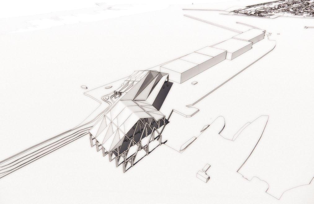
The scheme arrangement consolidates individual fragment system.
fragment investigations into a continuous architectural system. CONSOLIDATION
SECTION 4
FINAL DRAWINGS
Primary viewpoint from museum to jetty
Key axis for site reintegration from Aldrington Basin to Hove Lagoon
Secondary entrance from car park
Primary viewpoint into museum from street
Primary entrance into museum from street
Terminal operations
Views internally via junction
1. RESTAURANT
2. BAR/LOUNGE
3. SHOP/PUBLIC AMENITIES
4. W/C
5. BOAT CONSTRUCTION FACILITY
6. PLANT
7. STAFF ROOM
8. STAFF LOCKER ROOM
9. TERMINAL WAITING
10. BOARDING GATES
11. EXHIBITION
12. PRIMARY MUSEUM
14. BOAT CONSTRUCTION VIEWING DECK 15. HISTORIC BOAT + DOCK VIEWING DECK
13. KITCHEN
APPENDIX SECTION 5
FURTHER DEVELOPMENTS
The studied presented within this appendix informed the project’s structural thinking, spatial hierarchy and tectonic development, contributing to the final design without being directly adopted or translated into the final architectural language.
LANGUAGE DEVELOPMENT - BOAT STRUCTURE
Maritime vessel construction was studied to understand structural repetition, timber craft and ribbed assembly, informing the proposal’s emerging architectural language.
STRUCTURAL FRAGMENT EXPLORATION - CRUCK SYSTEM
Cruck systems were amplified and tested as a spatial and structural framework, exploring level changes through utilising the original method of abstraction with planar folds.
ESTABLISHING HIERARCHY
The aggregation of single and grouped frames tested how hierarchy could emerge through repetition, scale and enclosure.
STRUCTURAL ENVELOPE - FRAGMENT VARIATION
Alternative envelope configurations explored how structure could simultaneously provide an architectural identity through modern construction methods of timber utilisation.
APPLICATION OF ARTEFACT + PRECEDENT
Formal principles extracted from the artefact development were combined with research from Gare de Mons to generate a new structural language.
SPECULATIVE STAVE CHURCH / CRUCK RESPONSE
A speculative study tested how precedents of timber construction could be reinterpreted through contemporary structural and spatial strategies.
STRUCTURAL OPTIONS
Multiple structural configurations were evaluated to determine their impact on hierarchy, enclosure and spatial experience - including the use of mezzanines to use as viewing decks for the museum.
INTERNAL CONDITIONS
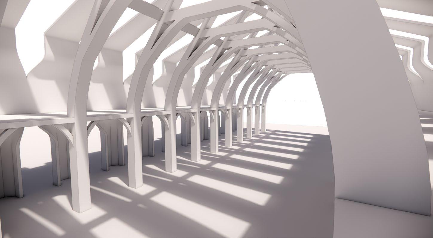
Interior studies of this fragment assessed how the system shaped light and occupation.
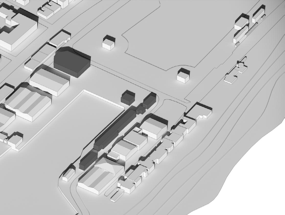
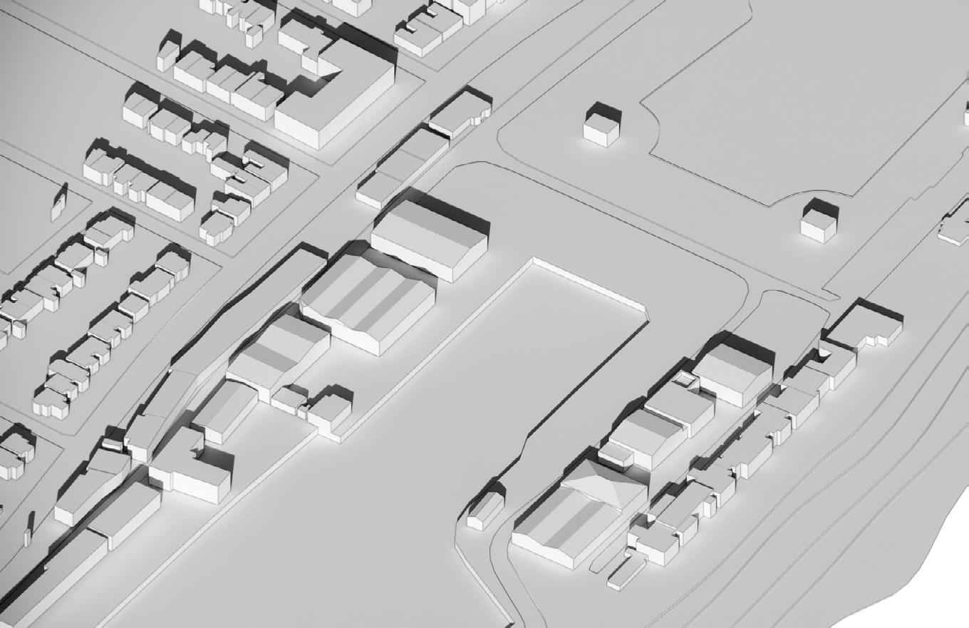
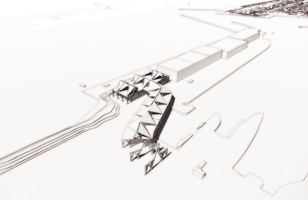
A sequence of massing models translated site constraints into speculative ideas SEQUENTIAL
constraints , circulation routes and programme requirements of architectural forms.
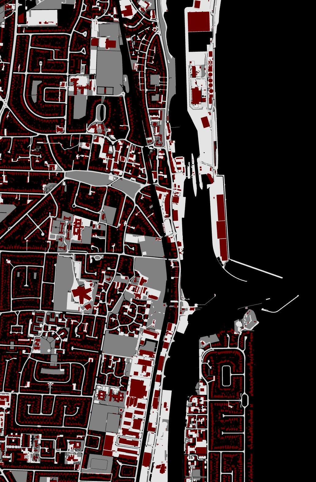
BUILDING MASSES
Buildings
Other Land Use
General Land/Road
The surrounding urban grain nearing the entrance to the site via ship was analysed to understand patterns of density and scale.
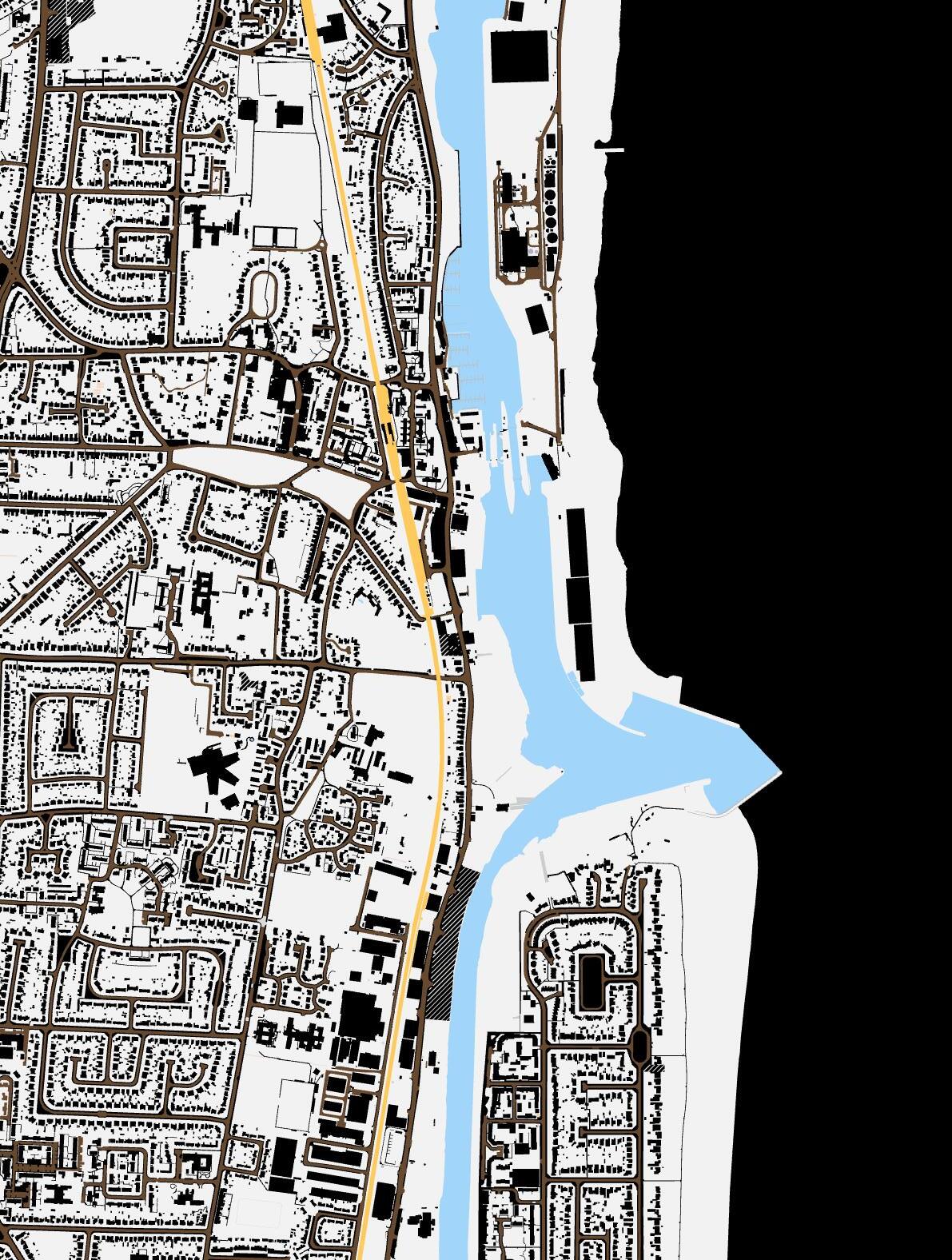
Waterways
Railway
Roads
Land
TRANSIT INFRASTRUCTURE
Existing transport networks were mapped to understand movement corridors nearing the site entrance via ship.
All work produced by Unit 14 Unit book design by Charlie Harriswww.bartlett.ucl.ac.uk/architecture
Copyright 2021 The Bartlett School of Architecture, UCL All rights reserved.
No part of this publication may be reproduced or transmited in any form or by any means, electronic or mechanical, including photocopy, recording or any information storage and retreival system without permission in writing from the publisher.
At the center of Unit 14’s academic exploration lies Buckminster Fuller’s ideal of the ‘The Comprehensive Designer’, a master-builder that follows Renaissance principles and a holistic approach. Fuller referred to this ideal of the designer as somebody who is capable of comprehending the ‘integrateable significance’ of specialised findings and is able to realise and coordinate the commonwealth potentials of these discoveries while not disappearing into a career of expertise. Like Fuller, we are opportunists in search of new ideas and their benefits via architectural synthesis. As such Unit 14 is a test bed for exploration and innovation, examining the role of the architect in an environment of continuous change. We are in search of the new, leveraging technologies, workflows and modes of production seen in disciplines outside our own. We test ideas systematically by means of digital as well as physical drawings, models and prototypes. Our work evolves around technological speculation with a research-driven core, generating momentum through astute synthesis. Our propositions are ultimately made through the design of buildings and through the in-depth consideration of structural formation and tectonic. This, coupled with a strong research ethos, will generate new and unprecedented, one day viable and spectacular proposals. They will be beautiful because of their intelligence - extraordinary findings and the artful integration of those into architecture.
The focus of this year’s work evolves around the concept of ‘Constructed Futures’. The term aims to describe architecture and as such fundamentally human future as the result of the architect’s highest degree of synthesis of underlying principles. Constructional logic, spatial innovation, typological organisation, environmental and structural performance are all negotiated in a highly iterative process driven by intense architectural investigation. Inspiration for inherent principles of organisational intelligence can be observed in both biotic and abiotic systems, in all spatial arrangements where it is critical for the overall performance of the developed order. Through the deep understanding of constructional principles, we will generate highly developed architectural systems of unencountered intensity where spatial organisation arises as a result of sets of mutual interactions. Observation as well as re-examination of civilisatory developments will enable us to project near future scenarios and position ourselves as avant-garde in the process of designing a comprehensive vision for the forthcoming. The projects will take shape as research based imaginative tales, architectural visions driven by speculation.
Thanks to: Seth Stein Architects, DKFS, ZHA, Foster and Partners, Minifie Architects, Buro Happold, Amanda Levete Architects, Penta Real Estate, RSHP