
Architecture Portfolio
JANKI SUVAGIYAHello,
My name is Janki Suvagiya. I am a graduate of the D.C. Patel School of Architecture in Gujarat, India and completed a three-year Architecture Technology program at Sheridan College, Mississauga. My goal is to develop sustainable and aesthetically - pleasing spaces to inspire and motivate others to imagine and create conditions for better living.
I am hardworking, a keen observer and ambitious individual. I am eagerly and energetically pursuing my lifelong desire of becoming a qualified architecture technologist. This portfolio contains my resume and features a sample of my selected school projects.
Thank you very much for taking a look!

JANKI SUVAGIYA
ABOUT ME
Female
20 October 1996
Languages
English
Gujarati
Hindi
CONTACT
+1(647)5402975
suvagiyajanki@gmail com
Etobicoke, Ontario
PERSONAL SOFTWARE
KNOWN
Ms office
Photoshop
SolidWorks
AutoCAD
Revit Sketchup
Inventor
My goal is to continually expand my professional knowledge and skills in architecture and design My dedication, hard work, and eagerness to learn make me a valuable asset on any team.
WORK EXPERIENCE
2023
2022
2022
2017 2021
2017
Architectural Designer at Premiere custom millwork and Fireplace ltd.
CO-OP Architecture Coordinator at St Michael’s Hospital (Unity Health Toronto)
CO-OP Project Coordinator at Sheridan College
CO-OP Project Coordinator at Sheridan College
Junior Architect and Interior design at Ojas Hirani architects and engineers
INTERN at Ojas Hirani architects and engineers
EDUCATION
2020 ARCHITECTURAL TECHNOLOGY
Architectural Technology from Sheridan College
2014
BACHELOR IN ARCHITECTURE
B.Arch. from D.C. Patel school of architecture, A.P.I.E.D, Vallabh V dhyanagar, Anand, Gujarat.
PERSONAL INTEREST
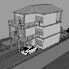
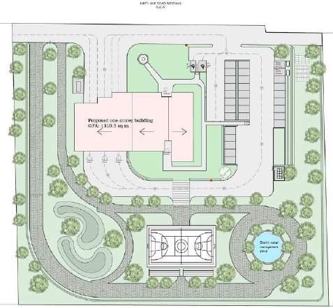
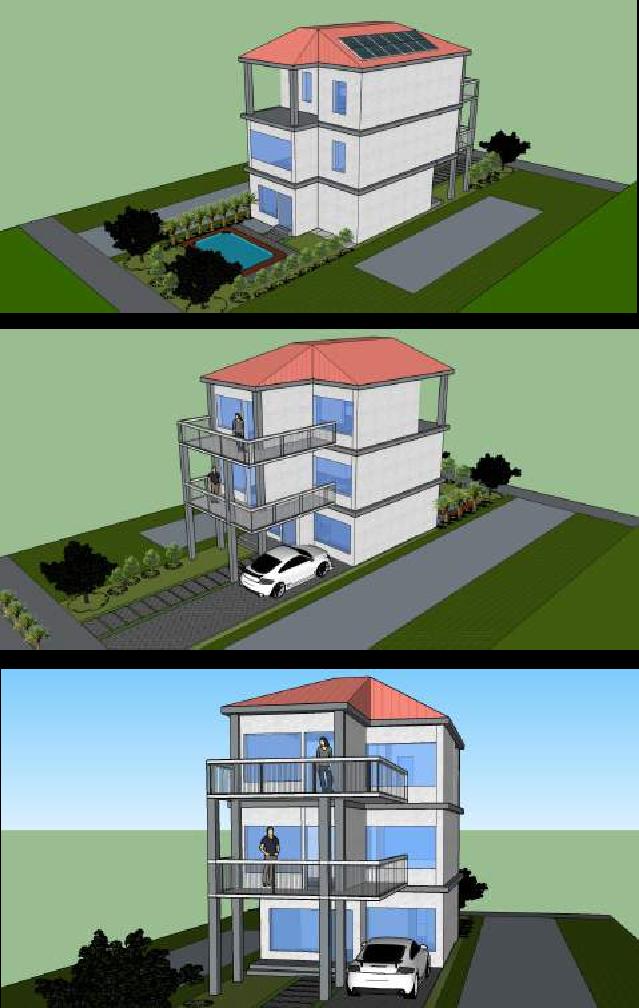
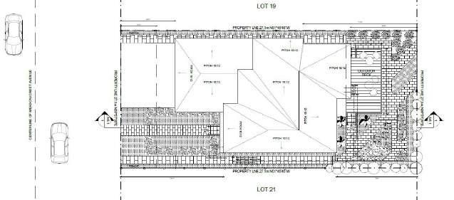
STUDIO 4 - FIRE STATION
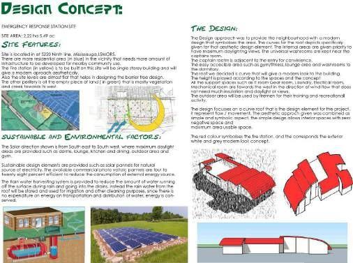
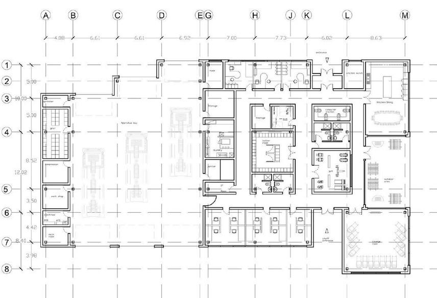
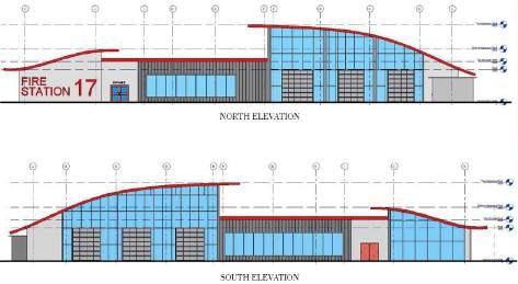
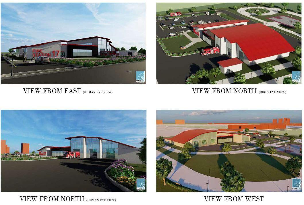

INTRODUCTION:
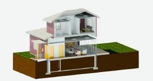
Keeping in mind challenges facing the world such as global warming and water shortages, this project includes some strategies that help in development of green building strategies such as LEED, Passive House Design, Zero Energy Design (ZED) and Zero Carbon Design etc.
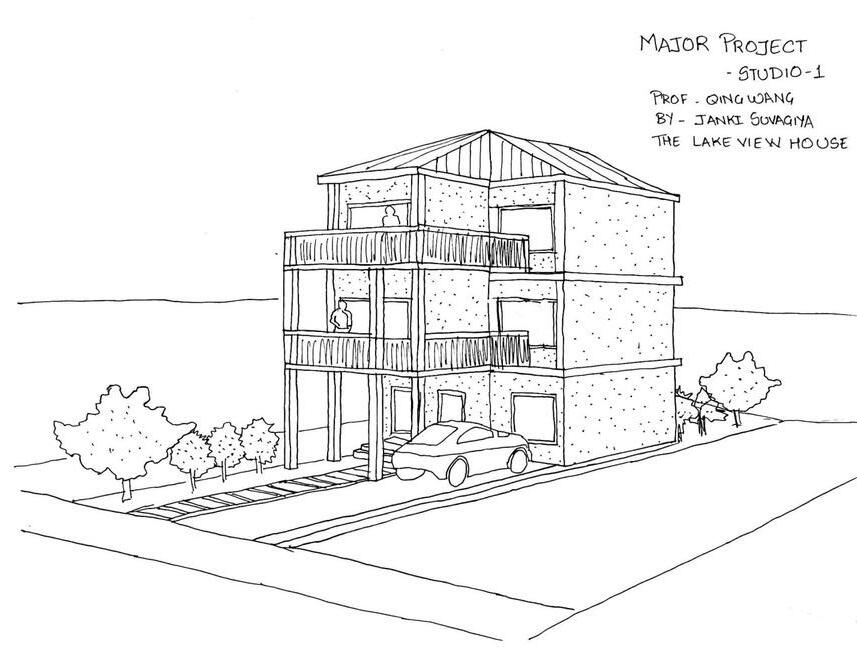
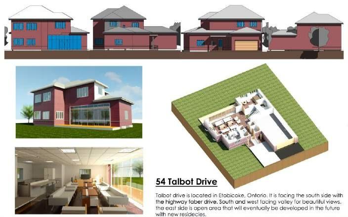
The client purchased land in the City of Mississauga and wishes to build a three-story dwelling that will maximize the use of a very small urban lot and employ sustainable design strategies to reduce its overall environmental impact and running costs.
CLIENT’S REQUIREMENTS: Ÿ
using sustainable design practices to develop a unique and creative solution for the house.
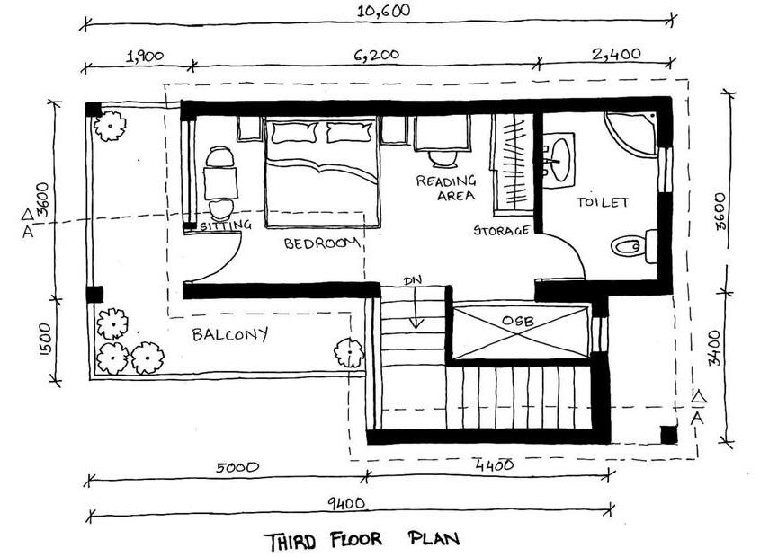
maximum total floor area is 98 sq. meters for 1-bedroom house, the bedroom must fit a queen size bed and should also include a reading/office space where the client can work.
the client wishes to maximize daylight entering each room.
not being fond of cooking or having a big kitchen, she only requires a small kitchen area.
she prefers a shower over a bathtub.
she needs a swimming pool for her enjoyment.
she needs a dressing area with maximum closet space
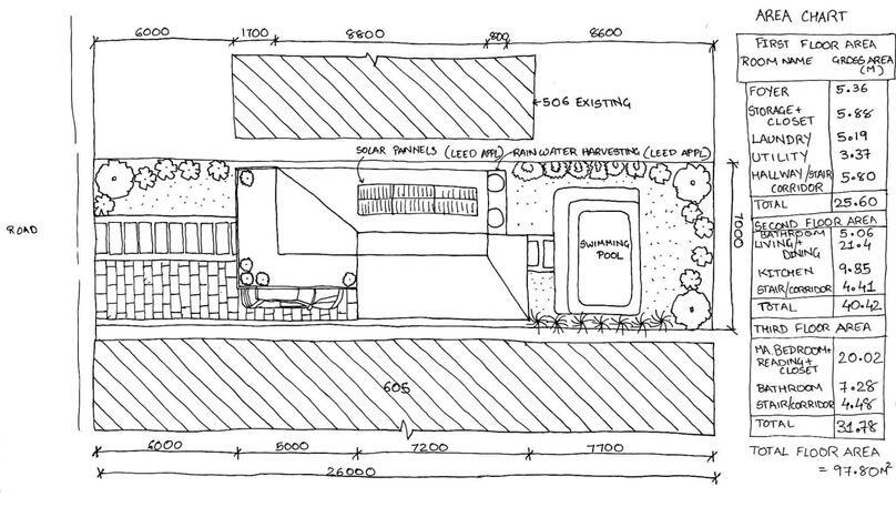
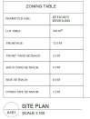
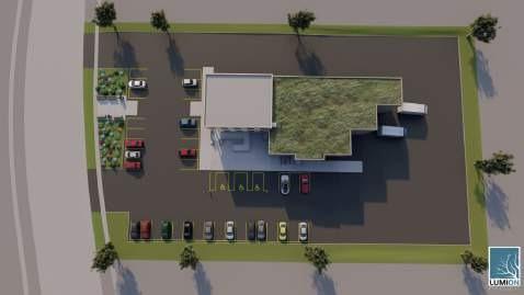
SITE PLAN:
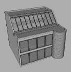
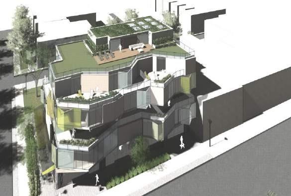
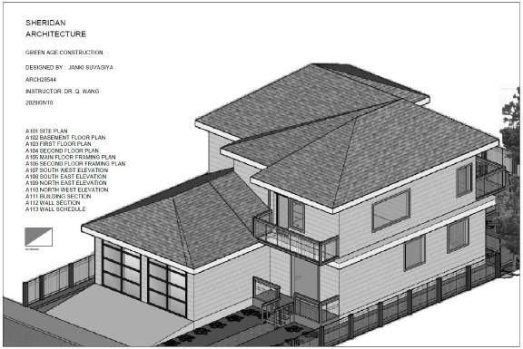
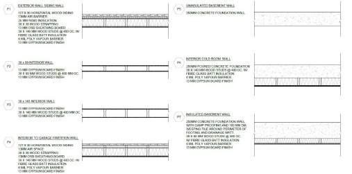
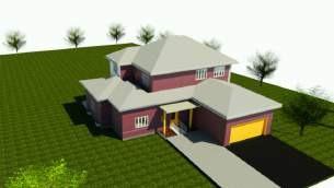
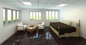
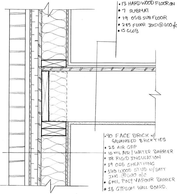
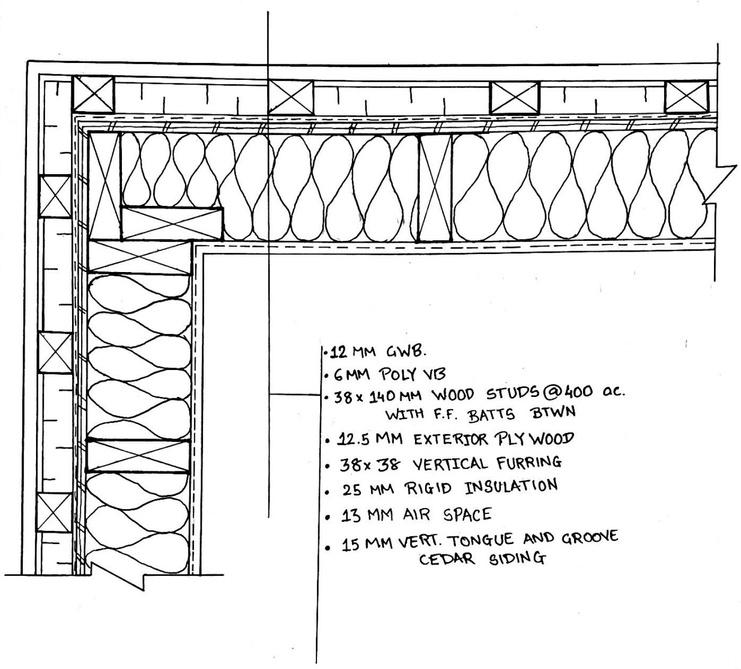
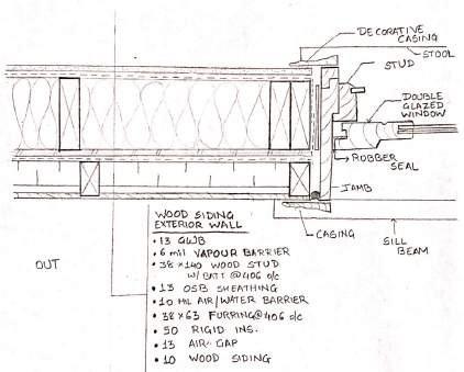
STUDIO 2 - RESIDENCE
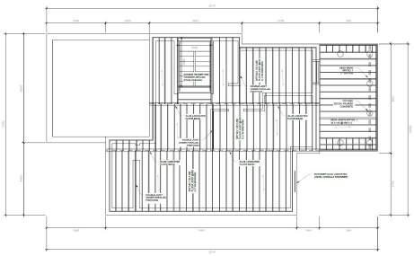

First oor framing:
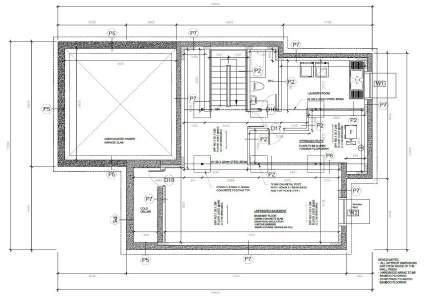
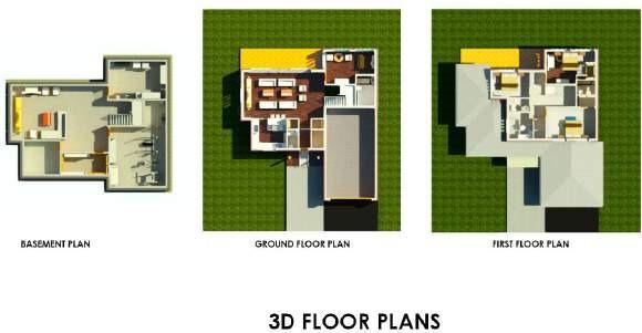
Basement plan:
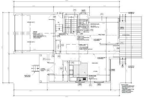
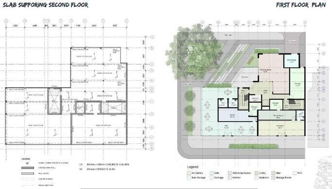
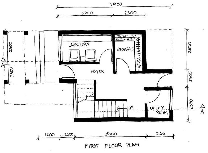
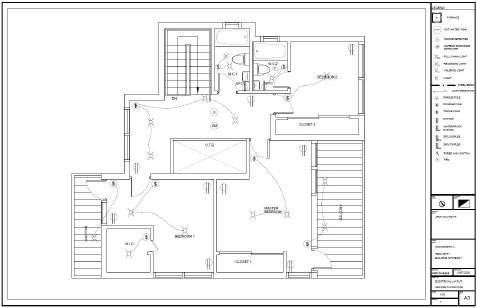
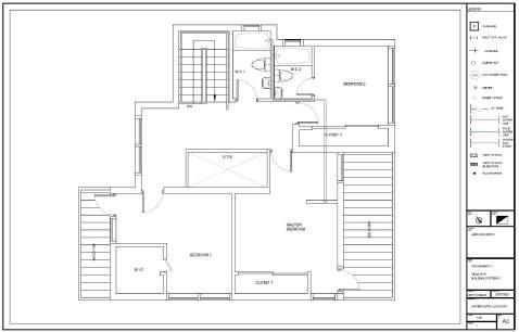
First floor plan
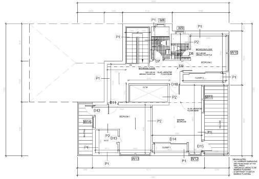
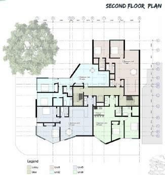
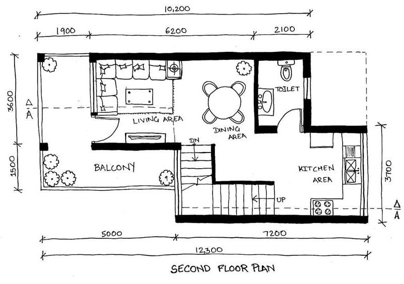
Second floor plan
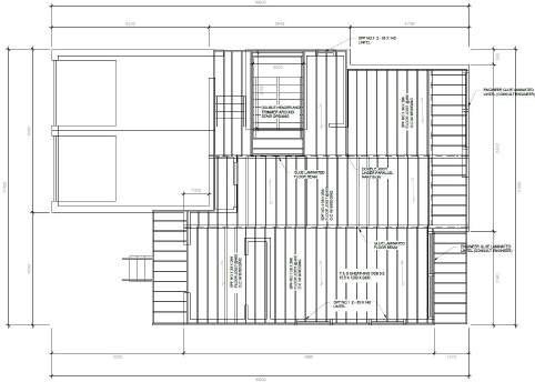
Second floor framing plan
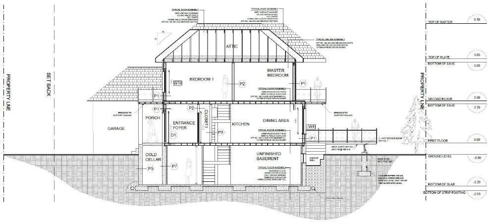


Designing using Revit Architecture:
Isometric views:
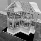
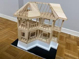
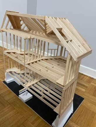
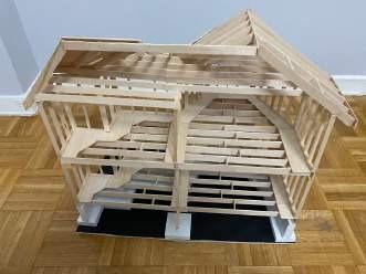
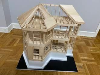
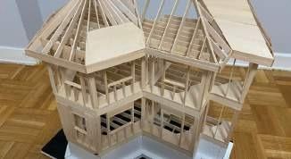
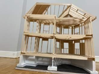
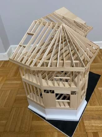
WOOD MODEL
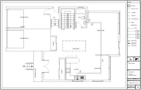
Electrical and Water Supply Layout:
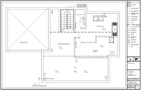
Basement oor plan (electrical)
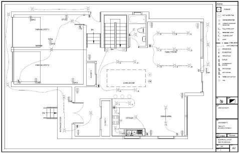
First oor plan (elctrical)
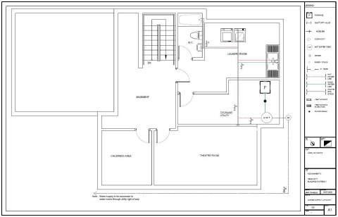
Basement oor plan (water supply)
First oor plan (water supply)
Electrical and Water Supply Layout:
Second oor plan (electrical)
Second oor plan (water supply)
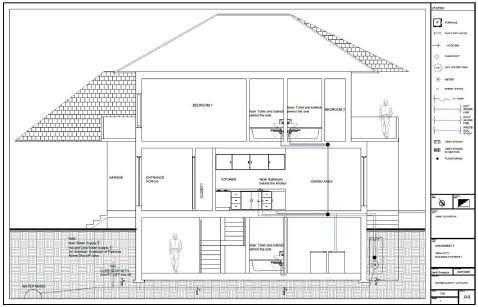
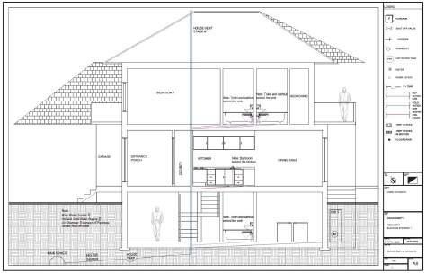
Section
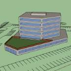
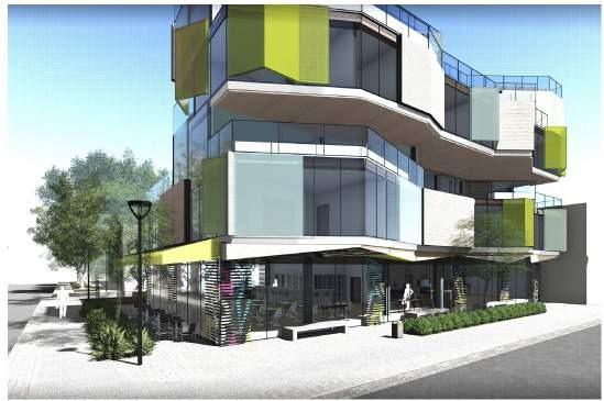
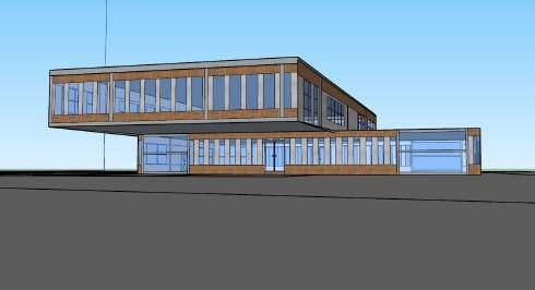
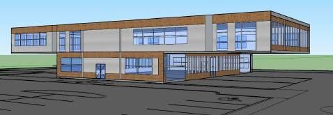
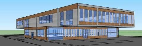
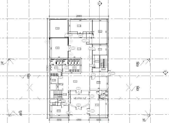
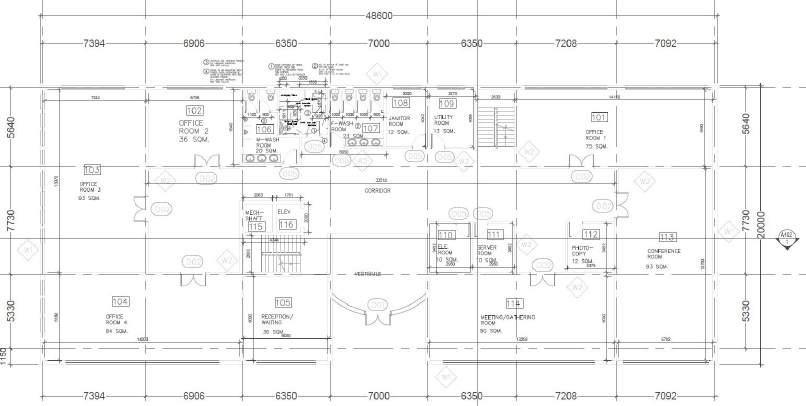
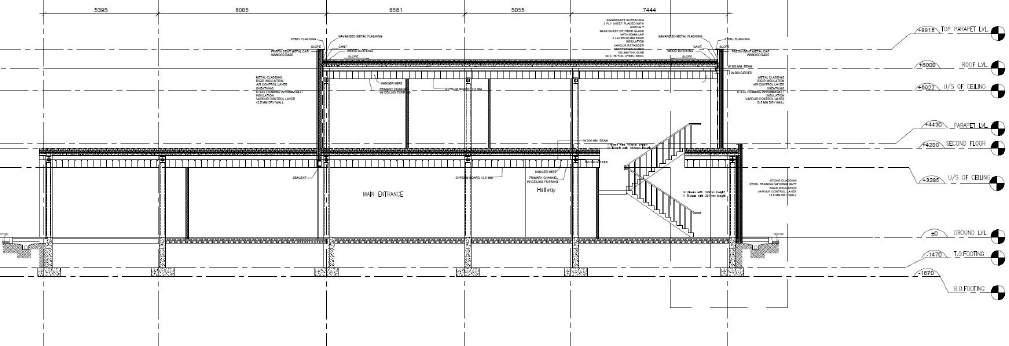
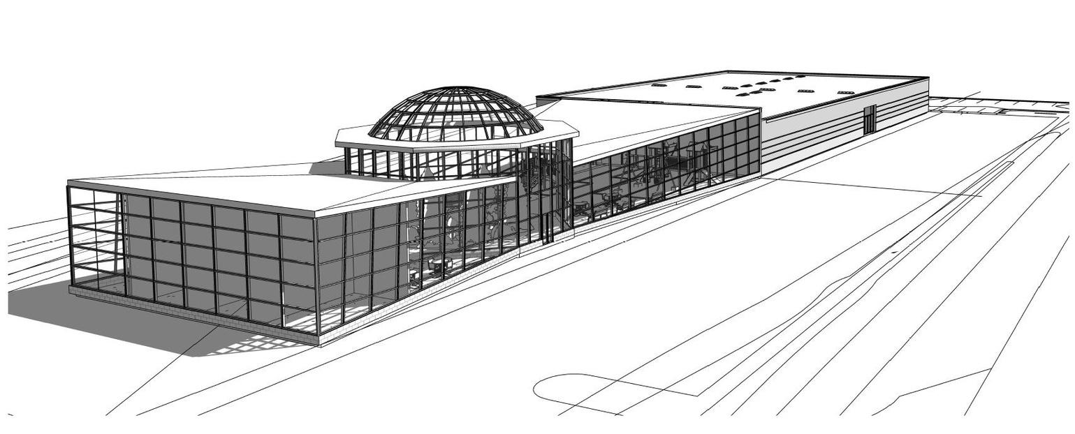
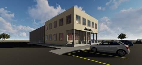
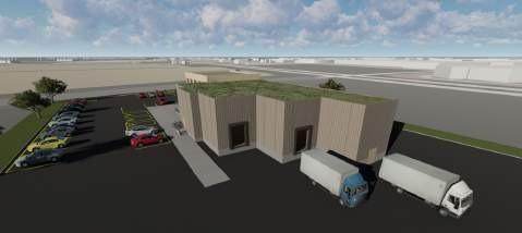
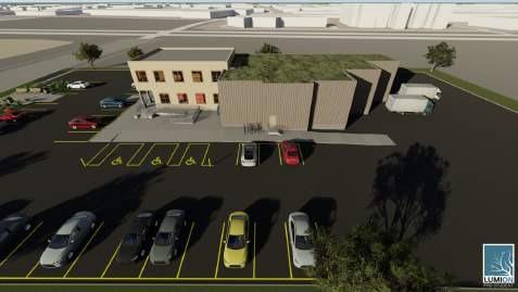
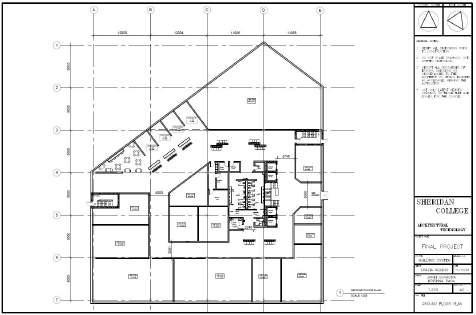
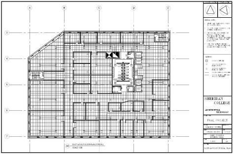
Introduction:
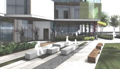
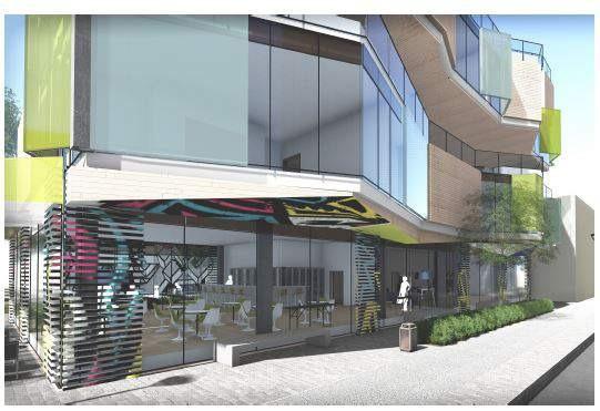
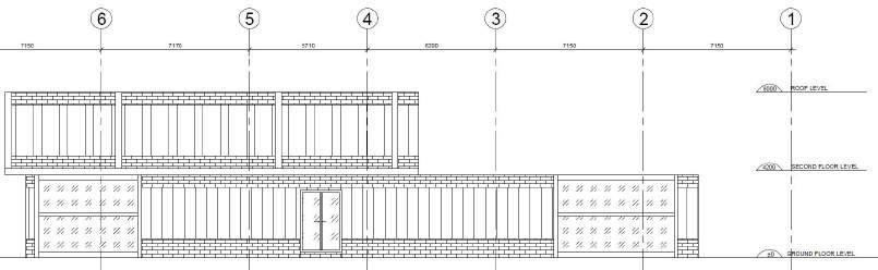
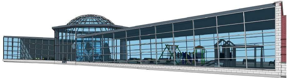
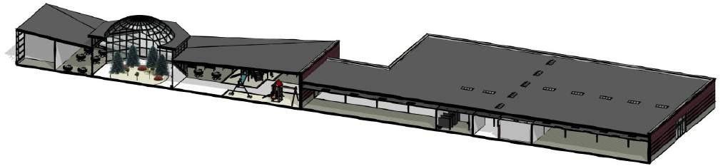
The building is a six storey mixed use building composed of multi-tenant retail space on the ground floor and multi-tenant office space on above floors. The site consists of two entrances: one for main entrance and one for the exit. The building shape is very similar to the edge of our site for convenience of design of parking and the building benefits from maximum use of space.
The Exterior materials used in this building are brick and aluminum cladding with curtain glass windows and doors for natural light to enter the building Also there is a dogleg staircase at the core that acts as a feature element at the entrance to the building. The other aspects of the building such as HVAC, Plumbing, Electrical, Fire and Life Safety are discussed further.
HVAC: Cooling, Heating and Air Handling
The building is using a VAV Duct system throughout. Thus the heating and cooling are dependent on each other.
The penthouse design consists of a 5000 x 5000mm cooling tower. Two 4500 x 1800mm chillers, and two 3000 x 1500 mm boilers are needed according to the building's HVAC system. The cooling tower is connected to the chillers and chillers are connected to the air handling units. The chillers consist of a cold fluid pumped to the air handling units. Inside the air handling units the hot air is passed through coils and gets cooled and passed to the building areas through duct work. The heated liquid found in the coils is sent to the chillers and gets cooled to pass through the ducts The same process takes place with the heaters when cold liquid found in the coils is sent to the boilers and gets heated to pass through ducts in winter.
The air handling units are connected to ducts which circulate the air via diffusers and return grills. 610 mm x 610 mm diffusers are located at certain intervals that are used for supply air.Also,610 x 610mm return grills are placed at each corner of the room for the return air.
Plumbing:
The main supply for the plumbing will be provided by the city main line. The main line connects to the pump room located in the basement area that is connected to other building areas for several uses. Water that comes from the main line is also used for the fire hydrants and washrooms. There is a washroom present at the core of the building of all floors and is a ached with a 600mm standpipe. All the fixtures are placed at the wall where the risers are present to supply water. The drains are located at all washroom and janitor areas to prevent any overflow of the water. The waste from the fixtures gets removed off site through a sanitary system, which then connects to the city sewage line. There are catch basins provided at the parking areas and around the main entrance of the building for drainage that leads to the storm water system.
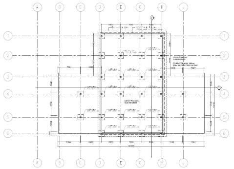
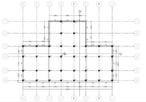
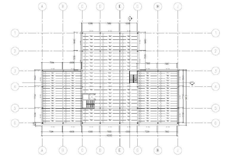
Mechanical Drawings for the project: (Commercial)
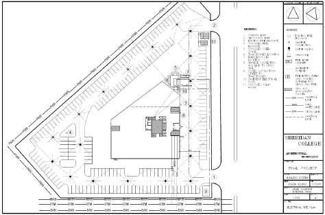
Electrical Site plan
First oor plan
Electrical:
A wide extend of lighting is introduced throughout the building. In each room, 610mm x 1220mm and 610mm x 610mm common light installations are affixed with decorative lights in the bathroom. They are by and large dispersed equally based on the ceiling le network in each room and dispersed enough all through the corridors. The lights are situated to not interfere with the other administrations, such as the diffusers, return grilles, and sprinklers. A server room is found on each floor of the building, which contains control and holds servers and an information center for phones and other telecommunication equipment. An electrical board can be found within the electrical room within the cellar, which acts as a intertwine to prevent any overburdening of the electrical framework.
The city control network runs control through the building's transformer, which runs through the transformer meter, to which the electrical board is connected. A generator is also located on location, which interfaces to the electrical panel in the electrical room in case of any control blackout.
Fire and life safety:
All through the building, sprinklers are installed to guarantee all areas receive fire suppressions in the event of a fire. A 6m breadth splash is utilized as a rule for the sprinklers, so that satisfactory spacing is provided The sprinklers are placed within the center of the ceiling lattice les for aesthetics. There are four elevators within the center of the building, each employing a equipped framework to function.
In case of crisis, elevators are modified to return to the ground floor and stay open. All four elevators have access to the penthouse, and one elevator has access to the basement. This ensures an elevator is available for the fire department to access all floors of the building. There are four fire cabinets on each floor containing fire extinguishers and fire hoses. Two are set next to the washroom, and an extra one is situated close to the staircase exit. One more is placed close to the security room. Standpipes situated close to the staircase permit for easy access to water. Emergency fire responders will approach the site from Living Arts Drive, where a Siamese connector is available nearby. Proposed fire hydrants are no more than 36m from each entrance. This allows the emergency fire responders easy access to a water source Existing the location, the fire truck is able to perform a 3-point turn back onto Living Arts Drive.
A single organized fire response plan is put in place to quickly identify emergencies and alert fire responders and all other emergency services, as well as caution tenants of an existing emergency so that the building is safely evacuated. As noted, there are two staircases on inverse sides of the building They are apart by more than half the span between the most distant corners of the building, to meet OBC guidelines. Moreover, the stair widths are 3m and the profundity of the arrivals in between are 1.75m, which permits an area of shelter during a fire for those stairs within the building. Passages all through the building are more than 12m in width to supply plentiful space for travel. The way of travel is planned to play down hindrance for ease of travel.
Mechanical Drawings for the project:
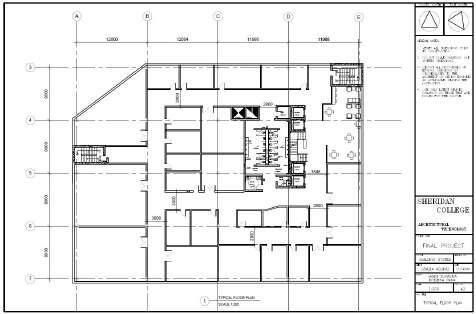
Typical oor plan
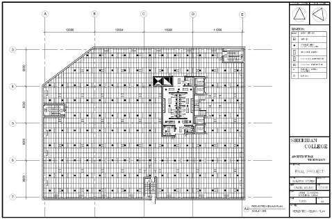
Reflected Ceiling plan
Mechanical Drawings for the project:
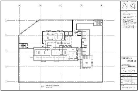
Penthouse oor plan
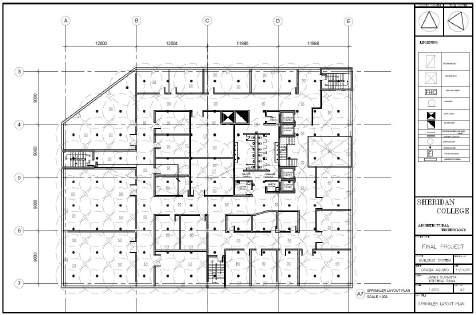
Sprinkler Layout plan
Duct Layout Typical plan
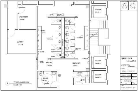
Typical Washroom plan
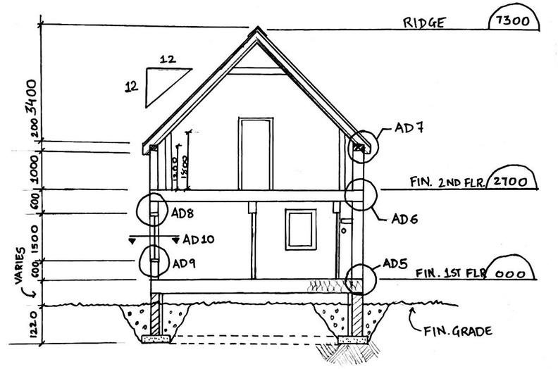
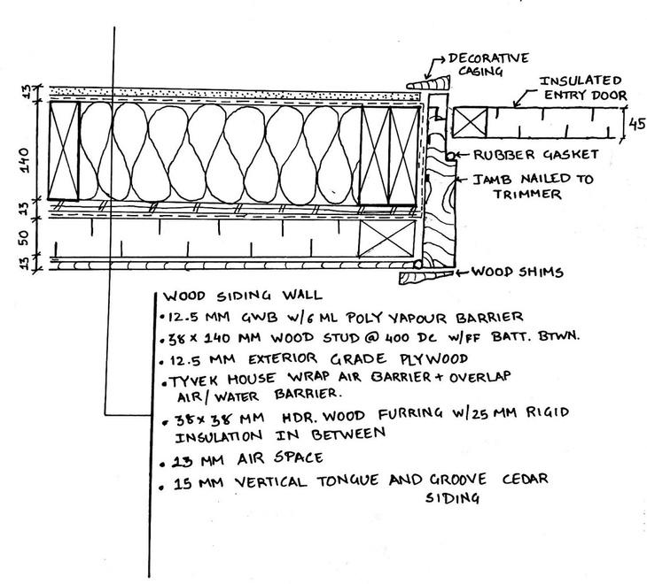
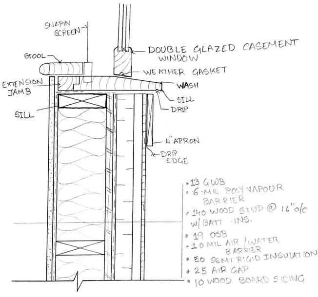
AD 9 (Window jamb detail) Door Jamb detail
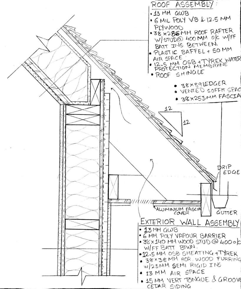
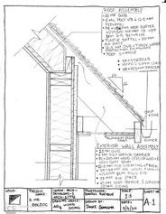
AD 7 (Roof to Wall assembly detail)