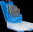
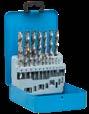
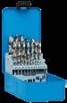
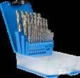
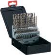
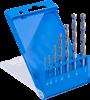
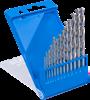
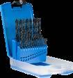
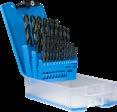
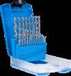
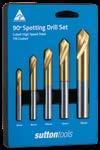
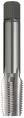
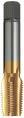
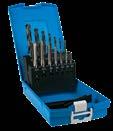
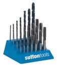
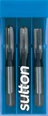
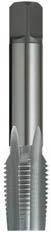
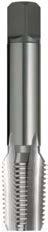
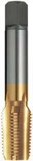
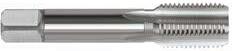
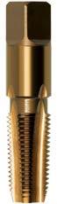
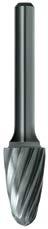
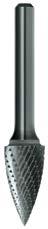
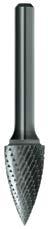
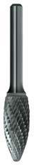
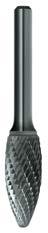
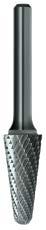
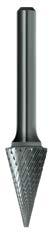
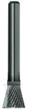
Sutton Tools item # system makes it easier to identify a product. The codes are based on a universal prefix and suffix system.
Prefix (Catalogue Code) – is alpha numeric, and is unique to a specific product range. The letter is relevant to the type of tool, and the number refers to a product range.
B - Burrs
C - Countersinks
D - Drills
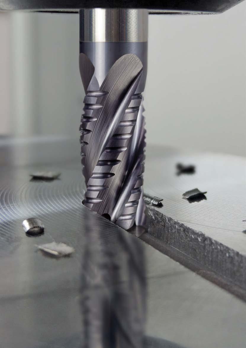
E - Endmills
L - Literature
M - Toolbits & Needle Files
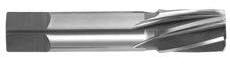
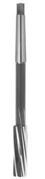
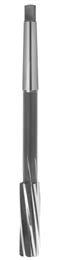
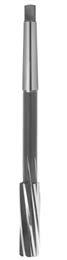
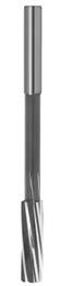
R - Reamers
T - Taps
Z - Tool Holders / Chucks
Suffix (Size Ref.) – in most cases is relevant to the diameter or size reference of an item and is based on a metric value.
For example 5mm = 0500, and 1/4" = 0635 (inch converted to decimal). Suffix can also refer to set code or number of pieces in a set.
Benefits of the coding system
• Range identification simplified.
• Search online by range using catalogue code.
Understanding your Sutton Tools Catalogue
Discount Group (A0202 – Z1108)
All product groups have been given a discount group number. These codes enable our distributor partners to identify their discounts on any particular product.
Material
This highlights what the product is made of. (e.g. VHM = Carbide, HSS = High Speed Steel) For the full list of explanation, refer to page 201 of the technical information section.
Surface Coatings
Many of our products have various surface coatings to improve the performance. Surface coatings improve productivity by increasing speeds and feeds and reducing friction related problems.
Symbols
For all of our product pages you will find symbols which depict what specifications these products were made to. Symbols have been used to simplify product identification. A full list of symbols can be found at the start of this catalogue.
Some common examples
D101 0150
Catalogue Code Size Ref.
#
ISO Taps
HSS Endmills Reamers
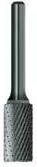
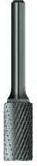
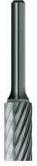
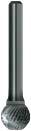
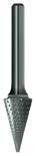
Carbide Burrs
ISO Taps
ISO Taps Metric, Forming, Single Coolant Groove
ISO Taps Metric, Gun, N
ISO Taps Metric, Spiral Flute, N 74
ISO Taps Metric, Straight Flute, N, Left Hand 70
ISO Taps Metric, Straight Flute, Oversize 71
ISO Taps Pipe, G (BSPF), Spiral Flute 116
ISO Taps Pipe, G (BSPF), Spiral Point Gun 115
ISO Taps Pipe, G (BSPF), Straight Flute 115
ISO Taps Pipe, National Series 119
ISO Taps Pipe, Rc (BSPT), Straight Flute 118
ISO Taps Pipe, Rp & Pg Series, Straight Flute 118
ISO Taps UNC, Forming, Single Coolant Groove 90
ISO Taps UNC, Gun, N 86
ISO Taps UNC, Machine Nut, Long Shank
ISO Taps UNC, Spiral Flute, N
ISO Taps UNC, Straight Flute, N 82
ISO Taps UNC, Straight Flute, N, Left Hand 84
ISO Taps UNEF, Straight Flute, N 96
ISO Taps UNF, Forming, Single Coolant Groove 101
ISO Taps UNF, Gun, N 98
ISO Taps UNF, Spiral Flute, N 100
ISO Taps UNF, Straight Flute, N 92
ISO Taps UNF, Straight Flute, N, Left Hand 94
Endmills 4 Flute, R30 N, Long 132
Endmills 4 Flute, R30 N, Regular 129
Roughers HR (fine), R30 NH, Regular 138
Roughers NR (normal), R30 WN, Long 136
Roughers NR (normal), R30 WN, Regular 134
Roughers Woodruff Cutter, Threaded 124
Slot Drills 2 Flute, R30 N, Long 127
Slot Drills 2 Flute, R30 N, Long 128
Slot Drills 2 Flute, R30 N, Regular 125
Slot Drills Ballnose, 2 Flute, R30 N, Long 137
ISO Taps
Carbide Burrs
Carbide Burrs
Carbide Burrs
Carbide Burrs
Technical Information
Technical Information
Technical Information
Technical Information
Technical Information
Technical Information
Technical Information
Technical Information
Technical Information Tapping Drill Size Chart (Fluteless)
- For use in machine applications Type N - For non-ferrous, - Type UNI - For difficult to machine materials
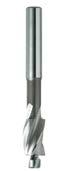
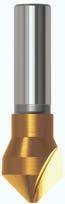
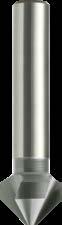
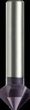
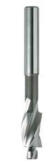
Countersinks Counterbore
- Solid pilot style
- 3 flute design
- Right-hand cutting
- Nominal size to suit metric socket head cap screws
- Cobalt High Speed Steel enables counterboring in high alloy steels
Catalogue Code C100
Discount Group B0709
Material HSS Co
Surface Finish Brt
Sutton Designation N
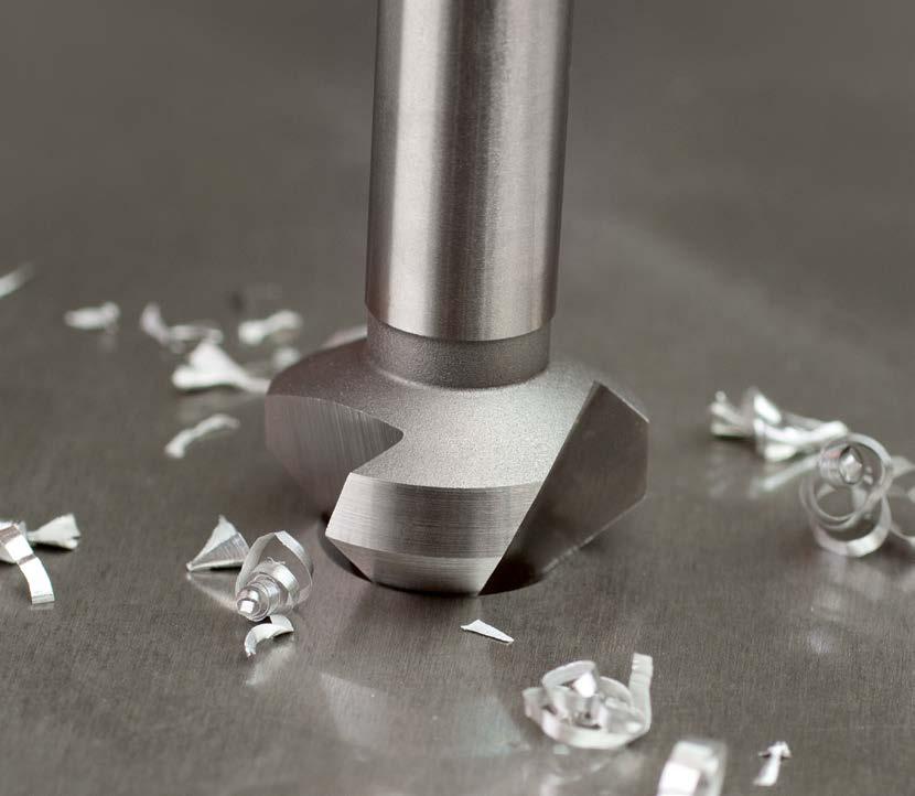
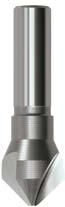
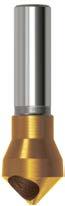
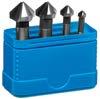
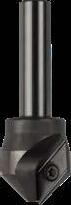
Chamfers Indexable Countersink with Carbide Insert
Suitable for both hand and machine operations
90° Standard Chamfer
Chatter-free countersinking and de-burring
Suitable for unstable machining at lower RPMs
Carbide strip design provides excellent chamfering surface and better tool life
ISO TAPS
• M, MF • UNC, UNF, UNEF, UN, UNS • BSW, BSF, BA, BSB
• Rc (BSPT), Rp (BSPPL), Pg Series, G (BSPF) • NPT, NPTF, NPSF
Special Taps Express Delivery Service…
Sutton Tools is a leading international Manufacturer of specialist cutting tools and is renowned for producing high performance, precision cutting tools specifically designed to individual customer requirements.
With comprehensive customer service and warehouse facilities, our Express Delivery Service enables us to meet your requirements more efficiently than ever before.
All Thread Forms
UN, Metric, UNJC, UNJF, MJ, UH, Pg, Whit, Rope forms & Acme and more!!
With our state of the art CNC grinding equipment almost any profile can be achieved. Feel free to discuss these with our Tech team.
*For
Within 24 hours*
Straight Flute Taps M3 to M127
• Spiral Taps M3 to M36
Within 48 Hours*
• Gun Taps M3 to M36
Within 5 Working Days*
Surface Finishes and Treatments:
• Steam Oxide
• Gas Nitride
• Titanium Nitride
• Chromium Nitride
Titanium Carbo-Nitride
• Titanium Aluminium Nitride
(BSPT), Rp (BSPPL), Pg, NPT, NPTF, NPSF
also be determined by referring to the material cross reference listing in the application guide at the back of this
For expert tooling recommendations, go to: www.suttonhps.com
ISO Taps Metric, Straight Flute,
- General purpose use
- Suitable for materials up to 1000N/mm2
- Through & blind holes
- Suitable for both hand and machine operations
14 piece set (intermediate)
Taps: M3, M4, M5, M6, M8, M10, M12
2.5, 3.3, 4.2, 5.0, 6.8, 8.5, 10.2mm
T385 0014
ISO Taps Metric, Straight Flute, N
- General purpose use
- Suitable for materials up to 1000N/mm2
- Through & blind holes
- Suitable for both hand and machine operations
- Depths up to approx. 1 x d1
Tap & Drill Sets
28 piece set (taper, inter, bott) (Discount Group Z0304)
Taps: M3, M4, M5, M6, M8, M10, M12
Drills: 2.5, 3.3, 4.2, 5.0, 6.8, 8.5, 10.2mm
-
-
ISO Taps Metric, Straight Flute, N, Left Hand
ISO Taps Metric, Straight Flute, N, Left Hand
- General purpose use
- Suitable for
- Through & blind holes
- Suitable for both hand and machine operations
- Depths up to approx. 1 x d1
ISO Taps Metric, Straight Flute, Oversize
- Oversize allowance to suit components for galvanize plating
- General purpose use, materials up to 1000N/mm2
- Through & blind holes
- Suitable for both hand and machine operations
- Depths up to approx 1 x d1
- Taper and inter leads available on request
- General purpose use
- Suitable for materials up to 1000N/mm2
- Through holes
- Depths up to approx. 3 x d1
-
Catalogue Code T395
Discount Group D0706
Material HSSE
Surface Finish TiN Sutton Designation N
- General purpose use
- Suitable for materials up to 1000N/mm2
- Blind holes
- Depths up to approx. 2.5 x d1
ISO Taps Metric, Spiral Flute, N
ISO Taps Metric, Forming, Single Coolant Groove
- For cold forming of threads in materials with good flow characteristics
- Through or blind holes
- Depths up to approx. 1.5 x d1
- TiN for longer tool life
ISO Taps Metric Fine, Straight Flute, N
-
- Suitable for materials up to 1000N/mm2
- Through & blind holes
-
ISO Taps Metric Fine, Straight Flute, N
- General purpose use
- Suitable for materials up to 1000N/mm2
- Through & blind holes
-
- Suitable for both hand and machine operations
to approx. 1 x d1
ISO Taps Metric Fine, Gun, N
- General purpose use
- Suitable for materials up to 1000N/mm2
- Through holes
- Depths up to approx. 3 x d1
ISO Taps Metric Fine, Gun,
- General purpose use
- Suitable for materials up to 1000N/mm2
- Through holes
- Depths up to approx. 3 x d1
Catalogue Code T408
Discount Group D0706
Material HSSE
Surface Finish TiN
Sutton Designation N
Geometry
ISO Taps Metric Fine, Spiral Flute, N
- General purpose use
- Suitable for materials up to 1000N/mm2
- Blind holes
- Depths up to approx. 2.5 x d1
- General purpose use
- Suitable for materials up to 1000N/mm2
- Through & blind holes
- Suitable for both hand and machine operations
- Depths up to approx. 1 x d1
-
ISO Taps UNC, Straight Flute, N, Left Hand
- General purpose use
- Suitable for materials up to 1000N/mm2
- Through & blind holes
- Suitable for both hand and machine operations
- Depths up to approx. 1 x d1
-
-
ISO Taps UNC, Straight Flute, N, Left Hand
Tolerance
- General purpose use
- Suitable for materials up to 1000N/mm2
- Through holes
- Depths up to approx. 3 x d1
-
- Depths up to approx. 3 x d1 Catalogue Code T424
Discount Group D0706 Material HSSE Surface Finish TiN
- General purpose use
- Suitable for materials up to 1000N/mm2
- Blind holes
- Depths up to approx. 2.5 x d1
ISO Taps UNC, Spiral Flute, N
ISO Taps UNC, Forming, Single Coolant Groove
- For cold forming of threads in materials with good flow characteristics - Through or blind holes - Depths up to
for longer tool life
ISO Taps UNC, Machine Nut, Long Shank
- Suited to long reach applications
- Suitable for materials up to 1000N/mm2
- Through holes
- Depths up to approx. 2 x d1
- General purpose use
- Suitable for materials up to 1000N/mm2
- Through & blind holes
- Suitable for both hand and
ISO Taps UNF, Straight Flute, N, Left Hand
- General purpose use
- Suitable for materials up to 1000N/mm2
- Through & blind holes
- Suitable for both hand and machine operations
- Depths up to approx. 1 x d1
ISO Taps UNF, Straight Flute, N, Left Hand
- General purpose use
- Suitable for materials up to 1000N/mm2
-
- Through & blind holes
for both hand and machine operations
- General purpose use
- Suitable for materials up to 1000N/mm2
- Through & blind holes
- Suitable for both hand and machine operations
- Depths up to approx. 1 x d1
Series
Tyre Valve Tap (UNS)
Stitching Tap
ISO Taps UNEF, Straight Flute, N
- General purpose use
- Suitable for materials up to 1000N/mm2
- Through & blind holes
- Suitable for both hand and machine operations
- Depths up to approx. 1 x d1
Tyre Valve Tap (UNS)
Stitching Tap UNEF
- General purpose use
- Suitable for materials up to 1000N/mm2
- Through holes
- Depths up to approx. 3 x d1
- General purpose use
- Suitable for materials up to 1000N/mm2
- Through holes
- Depths up to approx. 3 x d1 Catalogue Code T441
- General purpose use
- Suitable for materials up to 1000N/mm2
- Blind holes
- Depths up to approx. 2.5 x d1
ISO Taps UNF, Forming, Single Coolant Groove
- For cold forming of threads in materials with good flow characteristics
- Through or blind holes
- Depths up to approx. 1.5 x d1
- General purpose use
- Suitable for materials up to 1000N/mm2
- Through & blind holes
- Suitable for both hand and machine operations
- Depths up to approx. 1 x d1
- General purpose use
- Suitable for materials up to 1000N/mm2
- Through & blind holes
- Suitable for both hand and machine operations
- Depths up to approx. 1 x d1
ISO Taps BSW, Straight Flute, N, Left Hand
- General purpose use
- Suitable for materials up to 1000N/mm2
- Through & blind holes
- Suitable for both hand and machine operations
- Depths up to approx. 1 x d1
Catalogue Code T456
Discount Group D0702
Material HSS
Surface Finish Brt
Sutton Designation N
Geometry Left Hand
Chamfer Bottoming
Limit & Nut Tolerance Z3 LH Medium
- General purpose use
- Suitable for materials up to 1000N/mm2
- Through holes
- Depths up to approx. 3 x d1
- Suitable for materials
- Through
- Depths up to approx. 3 x d1
Catalogue Code T459
Discount Group D0706
Material HSSE
Surface Finish TiN
Sutton Designation N
Geometry
- General purpose use
- Suitable for materials up to 1000N/mm2
- Blind holes
- Depths up to approx. 2.5 x d1
Catalogue Code T462
Discount Group D0706
Material HSSE
Surface Finish TiN
Sutton Designation N
Geometry R40
ISO Taps BSW, Forming, Single Coolant Groove
- Suited to long reach applications
- Suitable for materials up to 1000N/mm2
- Through holes
- Depths up to approx. 2 x d1
Discount Group D0702
ISO Taps BSF, BSB & BA, Straight Flute,
- General purpose use
- Suitable for materials up to 1000N/mm2
- Through & blind holes
-
- Suitable for both hand and machine operations
ISO Taps BSF, BSB & BA, Straight Flute,
- Suitable for materials
- Through & blind holes
- Suitable for both hand and machine operations
- Depths up to approx. 1 x d1
ISO Taps
Pipe, G (BSPF), Straight Flute
- General
- Suitable for
- Through & blind holes
- Suitable for both hand and machine operations
- Depths up to approx. 1 x d1
ISO Taps Pipe, G (BSPF), Spiral Point Gun
- General purpose use
- Suitable for materials up to 1000N/mm2
- Through & blind holes
- Depths up to approx. 1 x d1
-
ISO Taps Pipe, G (BSPF), Straight Flute
ISO Taps Pipe, G (BSPF), Spiral Flute
- General purpose use
- Suitable for materials up to 1000N/mm2
- Through & blind holes
- Depths up to approx. 1 x d1
- General purpose use
- Suitable for materials up to 1000N/mm2
- Through & blind holes
- Suitable for both hand and machine operations
- Depths up to approx. 1 x d1
ISO Taps Pipe, Rc (BSPT), Straight Flute
- General purpose use
- Suitable for materials up to 1000N/mm2
- Through & blind holes
- Suitable for both hand and machine operations
- Taper pipe reamer recommended prior to tapping Rc (BSPT) thread forms
ISO Taps Pipe, Rp & Pg Series, Straight Flute
- General Purpose use for materials up to approx. 1000 N/mm2
- Through & blind holes
- Suitable for both hand and machine operations
Discount Group: D0702 Rc (BSPT) 1:16 Taper Rate
ISO Taps Pipe, National Series
- General purpose use, materials up to approx. 1000 N/mm2
- Used prior to tapping - For Rc (BSPT), NPT & NPTF tapered threads - Prolongs tap life, especially in tough materials
HSS ENDMILLS
• Slotting, Finishing, Roughing & Profiling • Short & Long Series
• General purpose & application specific geometries
recommendations, go to: www.suttonhps.com
Slotting
Finishing
Universal
Roughing
Profiling
Roughers Woodruff Cutter,
- For cutting key seats to suit standard imperial woodruff keys
Catalogue Code E178
Discount Group B0709
Material HSS
Surface Finish Brt
Sutton
Slot Drills 2 Flute, R30 N, Regular
- For soft steels & non-ferrous material
Catalogue Code E100
Discount Group B0502
Material HSS Co.8
Surface Finish Brt
Sutton Designation N Geometry R30 Shank Form (DIN 1835) A Shank Tolerance h6
Slot Drills 2 Flute, R30 N,
- For precision milling of slots & cavities
- Suitable for materials up to 1000 N/mm2
- For soft steels & non-ferrous material
Catalogue Code E100
Discount Group B0502
Material HSS Co.8
Surface Finish Brt
Sutton Designation N
Geometry R30
Shank Form (DIN 1835) A Shank Tolerance h6
Slot Drills 2 Flute, R30 N, Long
Slot Drills 2 Flute, R30 N, Long
- For long-reach slotting applications
- Suitable for materials up to 1000 N/mm2
- For soft steels & non-ferrous material
- TiAlN for longer tool life
Catalogue Code E184
Discount Group B0608
Material HSS Co.8
Surface Finish TiAlN
Sutton Designation N
Geometry R30
Shank Form (DIN 1835) A Shank Tolerance h6
E184
Endmills 4 Flute, R30 N, Regular
- For precision finish milling applications
- Suitable for materials up to 1000 N/mm2
Endmills 4 Flute, R30 N, Regular
- For precision finish milling applications
- Suitable for materials up to 1000 N/mm2
Catalogue Code E125
Discount Group B0502
Material HSS Co.8
Surface Finish Brt
Sutton Designation N
Geometry R30
Shank Form (DIN 1835) A Shank Tolerance h6
Endmills 4 Flute, R30 N, Regular
- For precision finish milling applications
- Suitable for materials up to 1000 N/mm2
- TiAlN for longer tool life
Catalogue Code E127
Discount Group B0502
Material HSS Co.8
Surface Finish Brt
Sutton Designation N
Geometry R30
Shank Form (DIN 1835) A Shank Tolerance h6
Endmills 4 Flute, R30 N, Long
- For roughing applications - NR geometry allows for heavy cuts - Suitable for materials up to 1000 N/mm2
- For roughing applications - NR geometry allows for heavy cuts
- Suitable for materials up to 1000 N/mm2
- TiCN for longer tool life
Discount
Material
Surface
Sutton
Roughers
For roughing applications
- NR geometry allows for heavy cuts
- Suitable for materials up to 1000 N/mm2
Catalogue Code E146
Discount Group B0402
Material HSS Co.8
Surface Finish Brt
Sutton Designation WN
Geometry R30 NR (coarse pitch)
Shank Form (DIN 1835) A Shank Tolerance h6
Slot Drills Ballnose, 2 Flute, R30 N, Long
Roughers HR (fine), R30 NH, Regular
- For roughing applications
- HR geometry allows for heavy cuts, in harder materials
- Suitable for materials up to 1300 N/mm2
- TiCN for longer tool life
E533 R35/38 Short E535 R35/38 Regular E559 R35/38 Corner Radius
R45-HRS
Performance Unequalled…
Harmony Endmills
The Harmony range of Endmills represents world’s latest technologies to provide increases in both performance and tool life. The key to successful milling is to minimise or eliminate the harmonic vibration produced in the cutting action.
The Harmony Endmill overcomes vibration, through the latest technologies in tool engineering:
AlCrN: G6 generation coatings... a quantum leap in tool wear resistance
Aluminium Chromium Nitride
The latest tool coating formula is Aluminium Chromium Nitride (AICrN). Coatings of this G6 generation developed, markedly expand the performance envelope versus conventional titanium based coatings (such as TiAIN, AITiN or TiCN).
Unique coating properties
The AICrN coating exhibits until now, an unmatched degree of oxidation resistance and hot hardness. These properties have triggered a quantum leap in tool wear resistance.
The bottom line: greater productivity!
Tools coated with AlCrN let you choose noticeably higher cutting speeds and allow you to more effectively exploit the potential of modern machine tools. You can produce more parts per time / unit to decisively boost the productivity of your manufacturing resources and hone your competitive edge.
Extraordinary performance gains have been demonstrated in dry and wet machining processes involving:
• Unalloyed steels
• High strength steels
• High hardness steels (up to 54 HRC)
Coating properties:
• Very high abrasion resistance
• High and constant temperature resistance
• Unrivalled oxidation resistance
• Titanium free coating
Reamers Hand
- For use by hand with suitable wrench - Suitable for tool rooms & workshop use
- Produces clean, accurate holes, to a H7 tolerance
Reamers Hand
- For use by hand with suitable wrench
- Suitable for tool rooms & workshop use
- Produces clean, accurate holes, to a H7 tolerance
Reamers Machine
- Machine use
- Suitable for toolroom & workshop use
- Produces clean, accurate holes, to a H7 tolerance
Reamers Machine
- Machine use
- Suitable for toolroom & workshop use
- Produces clean, accurate holes, to a H7 tolerance
Reamers Machine
- Machine use
- Suitable for toolroom & workshop use
- Produces clean, accurate holes, to a H7 tolerance
Reamers Chucking
- Machine use
- Suitable for toolroom & workshop use
- Produces clean, accurate holes, to a H7 tolerance
- Machine use
- For opening out existing holes
- Ideal for alignment in fabrication & construction work
Catalogue Code R104
Discount Group B0302
Material HSS
Surface Finish Brt
Sutton Designation N
Geometry L15
Reamers Taper Pin
- For use by hand with suitable wrench - For opening out parallel holes to suit 1:48 taper pins
Reamers Morse Taper Socket
- For use by hand with suitable wrench
Suitable
Rougher,
Reamers Morse Taper Socket
- For use by hand with suitable wrench
- Suitable for tool rooms & workshop use
- Rougher,
Reamers Taper Pipe
- For use by hand with suitable wrench
- Suitable for tool rooms & workshop use
- Used prior to tapping tapered thread forms 1:16 taper (BSPT, NPT)
- Prolongs tap life, especially in tough materials
Reamers Adjustable
- For use by hand with suitable wrench
- General purpose
- Adjustable size range
- TCA (Tungsten Chrome Alloy)
Reamers Adjustable
For use by hand with suitable wrench
General purpose
Adjustable size range
TCA (Tungsten Chrome Alloy)
CARBIDE BURRS
• Double Cut • Aluminium Cut • Comprehensive range of shapes
• Standard & extra length available • Sets • Die Grinder Kit
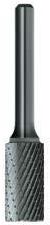
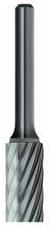
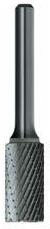
Carbide Burrs Cylindrical, Square End
- Double Cut, for rapid stock removal in the harder materials.
- The chisel tooth pattern not only minimises tool chatter but reduces the chip to a granular shape, in most materials.
- Al Cut, for rapid stock removal of soft materials such as: Aluminium, Brass, Copper, Plastics that would normally load other cuts
SA410 1/16 1-1/2 1/4 1/8 B200 SA410
SA420 3/32 1-1/2 7/16 1/8
SA430 1/8 1-1/2 9/16 1/8
SA510 1/4 2 3/16 1/8
SA140 3/16 2 5/8 1/4
SA100 1/4 2 5/8 1/4
SA200 5/16 2-1/2 3/4 1/4
SA300 3/8 2-1/2 3/4 1/4
SA400 7/16 2-3/4 1 1/4
SA500 1/2 2-3/4 1 1/4
SA600 5/8 2-3/4 1 1/4
SA700 3/4 2-3/4 1 1/4
SA900 1 2-3/4 1 1/4
Double Cut, Long Reach
SA3L6 3/8 6-3/4 3/4 1/4
SA5L6 1/2 7 1 1/4
Aluminium Cut
SA1AC 1/4 2 3/4 1/4
SA3AC 3/8 2-1/2 3/4 1/4
SA5AC 1/2 2-3/4 1 1/4
SA6AC 5/8 2-3/4 1 1/4
SA7AC 3/4 2-3/4 1 1/4
B200 SA420
B200 SA430
B200 SA510
B200 SA140
B200 SA100
B200 SA200
B200 SA300
B200 SA400
B200 SA500
B200 SA600
B200 SA700
B200 SA900
B210
B210 SA3L6
B210 SA5L6
B215 SA1AC
B215 SA3AC
B215 SA5AC
B215 SA6AC
B215 SA7AC
Cylindrical Square
Carbide Burrs Cylindrical, Square End
- Double Cut, for rapid stock removal in the harder materials.
- The chisel tooth pattern not only minimises tool chatter but reduces the chip to a granular shape, in most materials.
- Al Cut, for rapid stock removal of soft materials such as: Aluminium, Brass, Copper, Plastics that would normally load other cuts
Cylindrical Square
Carbide Burrs Cylindrical, Radius End
- Double Cut, for rapid stock removal in the harder materials.
- The chisel tooth pattern not only minimises tool chatter but reduces the chip to a granular shape, in most materials.
- Al Cut, for rapid stock removal of soft materials such as: Aluminium, Brass, Copper, Plastics that would normally load other cuts
SC410 3/32 1-1/2 1/2 1/8 B201 SC410
SC420 1/8 1-1/2 1/2 1/8
SC510 1/4 2 1/2 1/8
SC120 1/8 2 1/2 1/4
SC140 3/16 2 5/8 1/4
B201 SC420
B201 SC510
B201 SC120
B201 SC140
SC100 1/4 2 5/8 1/4 B201 SC100
SC200 5/16 2-1/2 3/4 1/4
B201 SC200
SC300 3/8 2-1/2 3/4 1/4 B201 SC300
SC400 7/16 2-3/4 1 1/4
SC500 1/2 2-3/4 1 1/4
B201 SC400
B201 SC500
SC600 5/8 2-3/4 1 1/4 B201 SC600
SC700 3/4 2-3/4 1 1/4
Double Cut, Long Reach
SC3L6 3/8 6-3/4 3/4 1/4
SC5L6 1/2 7 1 1/4
Aluminium Cut
SC1AC 1/4 2 5/8 1/4
SC3AC 3/8 2-1/2 3/4 1/4
SC5AC 1/2 2-3/4 1 1/4
SC7AC 3/4 2-3/4 1 1/4
Cylindrical Square
B201 SC700
B211
B211 SC3L6
B211 SC5L6
B216 SC1AC
B216 SC3AC
B216 SC5AC
B216 SC7AC
Cylindrical Round
Carbide Burrs Cylindrical, Radius End
- Double Cut, for rapid stock removal in the harder materials.
- The chisel tooth pattern not only minimises tool chatter but reduces the chip to a granular shape, in most materials.
- Al Cut, for rapid stock removal of soft materials such as: Aluminium, Brass, Copper, Plastics that would normally load other cuts
Cylindrical Square
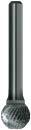
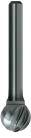
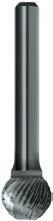
Carbide Burrs Ball Shape
- Double Cut, for rapid stock removal in the harder materials.
- The chisel tooth pattern not only minimises tool chatter but reduces the chip to a granular shape, in most materials.
- Al Cut, for rapid stock removal of soft materials such as: Aluminium, Brass, Copper, Plastics that would normally load other cuts
IMPERIAL
SD410 3/32 1-1/2 1/8
SD410 SD420 1/8 1-1/2 1/8 B202 SD420
1/4 1-3/4 1/8
SD510 SD110 1/8 2 1/4
SD140 3/16 2 1/4 B202 SD140
SD100 1/4 2 1/4
SD200 5/16 2-1/16 1/4
SD300 3/8 2-1/16 1/4
SD400 7/16 2-1/8 1/4
SD500 1/2 2-3/16 1/4
SD600 5/8 2-5/16 1/4
SD700 3/4 2-7/16 1/4
SD900 1 2-3/4 1/4
Double
Cut, Long Reach
SD3L6 3/8 6-3/4 1/4
SD5L6 1/2 6-1/2 1/4
Aluminium Cut
SD1AC 1/4 2 1/4
SD3AC 3/8 2-1/16 1/4
SD5AC 1/2 2-3/16 1/4
SD6AC 5/8 2-5/16 1/4
SD7AC 3/4 2-7/16 1/4
B202 SD100
B202 SD200
B202 SD300
B202 SD400
B202 SD500
B202 SD600
B202 SD700
B202 SD900
B212
B212 SD3L6
B212 SD5L6
B217 SD1AC
B217 SD3AC
Cylindrical Square
B217 SD5AC
B217 SD6AC
B217 SD7AC
Shape
Ball
Carbide Burrs Ball Shape
- Double Cut, for rapid stock removal in the harder materials.
- The chisel tooth pattern not only minimises tool chatter but reduces the chip to a granular shape, in most materials.
- Al Cut, for rapid stock removal of soft materials such as: Aluminium, Brass, Copper, Plastics that would normally load other cuts
Cylindrical Square
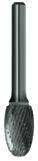
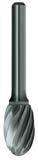
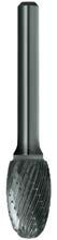
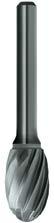
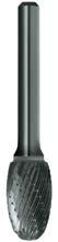
Carbide Burrs Oval Shape
- Double Cut, for rapid stock removal in the harder materials.
- The chisel tooth pattern not only minimises tool chatter but reduces the chip to a granular shape, in most materials.
- Al Cut, for rapid stock removal of soft materials such as: Aluminium, Brass, Copper, Plastics that would normally load other cuts
1/2 2-5/8 7/8 1/4
5/8 2-3/4 1 1/4
3/4 2-3/4 1 1/4
SE3AC 3/8 2-11/32 19/32 1/4
SE600
B218 SE3AC SE5AC 1/2 2-5/8 7/8 1/4 B218 SE5AC
Carbide Burrs Oval Shape
- Double Cut, for rapid stock removal in the harder materials.
- The chisel tooth pattern not only minimises tool chatter but reduces the chip to a granular shape, in most materials.
Cylindrical Square
Catalogue Code B303
Discount Group B0102 Material
Surface Finish
Cylindrical Round
Oval Shape
Ball Shape
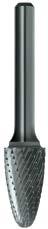
Carbide Burrs Tree Shape, Radius End
- Double Cut, for rapid stock removal in the harder materials.
- The chisel tooth pattern not only minimises tool chatter but reduces the chip to a granular shape, in most materials.
- Al Cut, for rapid stock removal of soft materials such as: Aluminium, Brass, Copper, Plastics that would normally load other cuts
SF410 1/8 1-1/2 1/4 1/8
SF410 SF420 1/8 1-1/2 1/2 1/8 B204 SF420
SF510 1/4 2 1/2 1/8 B204 SF510
SF100 1/4 2 5/8 1/4 B204 SF100
SF300 3/8 2-1/2 3/4 1/4
B204 SF300
SF400 7/16 2-3/4 1 1/4 B204 SF400
SF500 1/2 2-3/4 1 1/4
Cylindrical Square
B204 SF500
SF600 5/8 2-3/4 1 1/4 B204 SF600
SF700 3/4 2-3/4 1 1/4 B204 SF700
SF140 3/4 2-3/4 1 -1/4 1/4
SF150 3/4 3-1/4 1 -1/2 1/4
Double Cut, Long Reach
SF3L6 3/8 6-3/4 3/4 1/4
SF5L6 1/2 7 1 1/4
Aluminium Cut
SF1AC 1/4 2 3/4 1/4
SF3AC 3/8 2-1/2 3/4 1/4
SF5AC 1/2 2-3/4 1 1/4
SF6AC 5/8 2-3/4 1 1/4
B204 SF140
B204 SF150
B213
B213 SF3L6
B213 SF5L6
B219 SF1AC
B219 SF3AC
B219 SF5AC
B219 SF6AC
Tree Shape Radius Ball Shape
Carbide Burrs Tree Shape, Radius End
- Double Cut, for rapid stock removal in the harder materials.
- The chisel tooth pattern not only minimises tool chatter but reduces the chip to a granular shape, in most materials.
- Al Cut, for rapid stock removal of soft materials such as: Aluminium, Brass, Copper, Plastics that would normally load other cuts
Cylindrical Square
Shape
Shape Radius
Carbide Burrs Tree Shape, Pointed End
- Double Cut, for rapid stock removal in the harder materials.
- The chisel tooth pattern not only minimises tool chatter but reduces the chip to a granular shape, in most materials.
1/4 2 1/2 1/8
1/4 2 5/8 1/4 B205 SG100
SG200 5/16 2-1/2 3/4 1/4 B205 SG200
SG300 3/8 2-1/2 3/4 1/4 B205 SG300
SG130 1/2 2-1/2 3/4 1/4 B205 SG130
SG500 1/2 2-3/4 1 1/4 B205 SG500
SG600 5/8 2-3/4 1 1/4 B205 SG600
SG700 3/4 2-3/4 1 1/4
B205 SG700
SG150 3/4 2-3/4 1-1/2 1/4 B205 SG150
METRIC
Double Cut
SG200 SG300 9.5 64.0 19.1 6.0 B305 SG300
SG130 12.7 64.0 19.1 6.0
SG500 12.7 70.0 25.4 6.0
B305 SG130
B305 SG500
Tree Shape Radius
Tree Shape Pointed
Oval Shape
Ball Shape
Cylindrical Round
Cylindrical Square
Carbide Burrs Flame Shape
- Double Cut, for rapid stock removal in the harder materials.
- The chisel tooth pattern not only minimises tool chatter but reduces the chip to a granular shape, in most materials.
Carbide Burrs Taper Shape
- Double Cut, for rapid stock removal in the harder materials.
- The chisel tooth pattern not only minimises tool chatter but reduces the chip to a granular shape, in most materials.
- Al Cut, for rapid stock removal of soft materials such as: Aluminium, Brass, Copper, Plastics that would normally load other cuts
Carbide Burrs Taper Shape
- Double Cut, for rapid stock removal in the harder materials.
- The chisel tooth pattern not only minimises tool chatter but reduces the chip to a granular shape, in most materials.
Catalogue Code B307
Discount Group
Surface
Carbide Burrs Cone Shape
- Double Cut, for rapid stock removal in the harder materials.
- The chisel tooth pattern not only minimises tool chatter but reduces the chip to a granular shape, in most materials.
METRIC
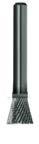
Carbide Burrs Inverted Cone Shape
- Double Cut, for rapid stock removal in the harder materials.
- The chisel tooth pattern not only minimises tool chatter but reduces the chip to a granular shape, in most materials.
Catalogue Code B209
Discount
Surface
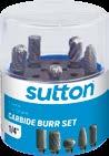
Carbide Burrs Sets
All sets packed in ABS case (industrial grade plastic material).
Catalogue Code B900
Discount Group B0102
Material VHM
Surface Finish Brt ApplicationGeometryShank 1/4"
B900 SCB100
B900 SCB100
B900 SCB300 B900 SCB500 B900 SCB5
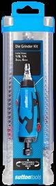
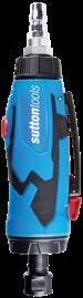
Carbide Burrs Die Grinder Kit
Sutton Tools Die Grinder is the perfect tool for detailed metal or woodwork providing precise clean cuts. Use it with Sutton Tools range of carbide burrs to sculpt and shape harder materials.
Suitable for grinding back and neatening welds, porting, polishing and woodworking applications.
Features:
• Quick release attachment
• Trigger with safety latch prevent accidental operation
• Adjusting knob controls speed of rotation
Specifications:
• Collet capacity: 1/8, 1/4, 3 & 6mm
• No load speed: 25,000 RPM
• Air Pressure: 90 PSI
• Overall Length: 165mm
• Net Weight: 557g
Die Grinder Kit Pneumatic Die Grinder 4 collets: 1/8, 1/4, 3 & 6mm 2 x wrenches
Note: Reduce cutting speeds by 50% when using long shank carbide burrs.
Electrical safety laws of electricity electrical conductors
Electrical codes and standards
Electrical conduit and conduit bending
Electrical formulae and conversion factors transformers and motors
Electrical socket-outlets, switches and enclosures
• Led lighting, fibre optics and data cabling and more…
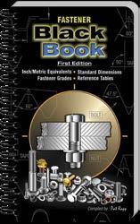
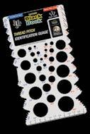
Fastener Black Book - 248 Pages of:
Screw thread fundamentals
• Standards
• Heat treatment
• Thread classes
Grades
Materials and coatings
• Failures and corrosion
Thread terminology
Tolerances
• Fastener strengths and markings
Hydrogen embrittlement
• Screw thread profiles
Dimensional specifications
DIN / ISO / ANSI
Galling
Material selection
• Torque control
• Platings
• Elevated temperature effects
Discount Group: Z0502
Other Cutting Lubricant, Venom
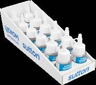
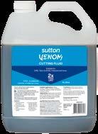
Venom Endurance+ Cutting Fluid
Venom Endurance+ Cutting Fluid is a highly efficient cutting and lubricating fluid. Formulated to increase tool life and enhance cutting performance in a broad range of metals including carbon steel, aluminium alloys, copper, brass, bronze and stainless steel. Mild clinging action helps fluid adhere to the tool and part when vertical work is required.
*Only available in multiples of 6 **Only available in multiples of 12
Features
• Low melting point – adheres to cutting edge for greater tool protection
• Not affected by coolant
• Lowest torque required for higher performance
• Reduced friction for extremely high quality surface finish
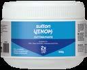
Venom Extreme Power Cutting Paste
Formulated for superior tool life and cutting performance in carbon steel, aluminium alloys, copper, bronze, stainless steel, nickels, titaniums and other super alloys.
Venom Extreme Power Cutting Paste is a high performance low melting point lubricant specifically designed to adhere to the cutting edges, even when using additional coolants.
Features
• Reduces torque and friction
• Extends tool life
• Improves surface finish
• Accurate thread quality
• Environmentally friendly mineral oil base with 10% organic coconut oil. Free from Trichloroethane – low odour.
CUTTING SPRAY
Features
• Comfort nozzle allows an accurate spray flow in hard-to-reach working areas
• Precise spray flow within 1.5m range
• Non-flammable
• Reduces torque and friction
• Extends tool life
• Improves surface finish
• Accurate thread quality
• Environmentally friendly mineral oil base with 10% organic coconut oil. Free from Trichloroethane – low odour.
• Suitable for use in non-ventilated areas
TECHNICAL
Regrinding Service… Reduce your production costs
Sutton Tools continue to reinvest to provide a ‘complete’ range in cutting tool products and services. Our regrinding service returns tools to ‘as new’ condition. Quality is guaranteed from the CNC grinding machines which are operated by highly experienced personnel, using advanced technology. A full regrinding service is offered in Europe. HSS and carbide tooling can be reconditioned by our highly experienced personnel, with reproducible, high quality results, every time.
We regrind HSS Powdered Metallurgy and grades of Solid Carbide, complemented by fifth generation thin film coatings.
Sutton Tools Recoating Service
In Europe we provide a full regrinding service for Sutton Tools distributors. Using world-leading technology, coatings are available to solve a wide range of problems relating to friction and wear, thereby improving tool performance and increasing tool life, up to 300-1000% compared to uncoated.
Send & Return Service
Sutton Tools re-sharpening boxes will be provided for safe shipment of your tools for servicing. Simply fill in the request form, and we will return the tools to ‘as new’ condition as instructed. Contact us for your Sutton Tools re-sharpening box and request form.
Application Guide Materials - Workpiece
4
4
5
6
6
6
6
6
6
6
6
6
6
6
6
6
6
12
12
14.1
14.1
14.2
Application Guide Materials - Workpiece
31 1.4558 X 2 NiCrAITi 32 20 NA 15
31 1.4562 X 1 NiCrMoCu 32 28 7 N
31 1.4958 X 5 NiCrAITi 31 20
31
32
35
35 3.7115 TiAl5Sn2
36 3.7025 Ti 1 2 TA 1 R
36
37 3.7145 TiAl6Sn2Zr4Mo2Si
37 3.7195 TiAl 3 V 2.5
37 TiAl4Mo4Sn4Si0.5
40
40
Application Guide Speeds & Feeds - HSS Drills
VDI Material Group
N N Non-Ferrous Metals, Aluminiums & Coppers
S S Titaniums & Super Alloys
H H Hard Materials (≥ 45 HRC) H
^ VDI 3323 material groups can also be determined by referring to the workpiece material cross reference listing. Refer to main index of this section. For expert tooling recommendations, go to: www.suttonhps.com
JOBBER
Notes on Drilling
1. Step feeding or pecking is required for drilling greater than 3 x Ø.
2. When drilling cast surface & black (ie: not machined surface), reduce drilling speed by
3. For optimal positional accuracy and hole size, the use of spot drills is recommended prior to drilling desired hole, refer to our standard range (D175).
4. For hole depths greater than 7 x Ø, pre-drill initially to pilot start for more accurate hole position and eliminate drill wandering. The pilot can be drilled with short rigid drill, approximately. 3 x Ø in depth and reduced feed to ensure accurate pilot hole.
4.0
Application Guide Speeds & Feeds - Taps
ISO VDI Material Group
P A Steel
M R Stainless Steel
K F Cast Iron
N N Non-Ferrous Metals, Aluminiums & Coppers
S S Titaniums & Super Alloys
H H Hard Materials (≥ 45 HRC) H ^ VDI 3323 material groups can also be determined by referring to the workpiece material cross reference listing. Refer to main index of this section. For expert tooling recommendations, go to: www.suttonhps.com
Notes on Tapping
1. The speeds listed above are a recommendation only, and are based on depth of thread listed, speeds can be adjusted on application. As a general rule; -If hole depth required is less than above mentioned = increase speed -If hole depth required is more than above mentioned = reduce speed
2. Taps must be driven by the square to eliminate slippage, eg, ER-GB collets (square drive).
3. When using spiral flute taps with length compensation tapping attachment, it is recommended to short pitch the feed 95%, to eliminate tap cutting oversize, eg. M6x1 @ 1000RPM, Feedrate= 950mm/min.
Application Guide Speeds & Feeds - HSS Endmills
N N Non-Ferrous Metals, Aluminiums & Coppers
S S Titaniums & Super Alloys
H H Hard Materials (≥ 45 HRC)
^ VDI 3323 material groups can also be determined by referring to the workpiece material cross reference listing. Refer to main index of this section. For expert tooling recommendations, go to: www.suttonhps.com
Notes on Milling
1. Above values are guidelines for the size and type of cut nominated.
2. For long series tools, reduce speed by 40% and feed by 20%.
• Spring or backlash in drill press, fixture or work
•
•
•
• • Feed too heavy
Cutting speed too high
Dry cutting, no lubricant at cutting edges
•
Drill web (core) diameter too big
• Fixture/Clamping not rigid
• Unequal angle or uneven length of cutting edges
• Spindle run-out/Loose spindle
• Bad fit between shank taper & socket. The drive & alignment is controlled by the taper fit
Regrind correctly
Remove drill from hole and to clear flutes
Check each item for rigidity and alignment
Reduce Feed
Reduce speed
Apply cutting fluid
Thin web to original size
Secure job firmly
Regrind to same lip lengths and angles
Check machine
Remove dirt, nicks or burrs, or replace worn socket
Wrong tap, cutting geometry of the tap is not suitable for this operation
Tap hole diameter is undersize
Misalignment - tap hole position, or angle is not correct
Use correct tap for the material group. See Expert Tool Selector, at www.suttontools.com/expert-tool-selector
Tap hole diameter should be in accordance to DIN336 or respective standard. For cold forming taps, a special hole diameter is needed.
a) check workpiece clamping
b) check machine settings • The axial machine spindle movement is not free and easy
•
Cold welding on the thread flanks of the tap
• Poor guidance of the tap because of little thread depth
• Speed is too high
• • • Chip clogging
•
•
•
• •
•
• • The lubrication wrong, additives or the coolant supply is not sufficient
Spiral fluted taps are over pressured in the initial cutting phase (retracting pulling force)
Spiral pointed taps (gun taps) are not receiving enough pressure in the initial cutting phase
Tolerance on the tap is not identical to the tolerance on the drawing or on the gauge
Wrong initial cutting pressure has been used or the machine spindle is not moving along its axis free and easy
• • Tap is over loaded, either from coarse pitch and/or tough material
• Cold welding, material build-up (pick-up)
• • Hardened walls in drilled hole
• Over loading of teeth in the chamfer area
a) use mechanical feed
b) use tap holder with length compensation
a) use a new tap
b) improve and check lubrication
c) remove cold welding area from tap
d) use tap with surface treatment or coatings
a) use mechanical feed
b) use tap that has better guiding characteristics
a) improve lubrication
b) lower speed
a) use tap with different flute form
b) use coated taps
c) use tap set
Make sure that the coolant is correct and that the supply is sufficient
Spiral fluted taps should only be lightly pushed into the tap hole until it begins to cut. The tap holder should immediately begin to apply tension to the tap.
Spiral pointed taps and even left hand spiral flute taps must have a stronger pressure until they begin to cut.
The tap holder should immediately begin to apply pressure to the tap (pushing force)
Use a tap which has a correct tolerance
a) use mechanical feed
b) use tap holder with length compensation
Use set of taps
a) improve coolant supply, use taps with surface treatments or coatings
b) check if surface treatment is correct for this application
a) use drill best suited to material being drilled
b) use new drill or boring tool
c) resharpen drilling or boring tools
d) if possible, heat treatment and coatings should only be made after threading
a) use a longer chamfer (check if the tap hole is blind hole or through)
b) use increased number of teeth in the chamfer area by selecting tap with increased number of flutes
• Tap hole chamfer is missing or wrong Countersink tap hole chamfer with correct angle
• Tap crashed against the bottom of tap hole
Use tap holder with length compensation and over load clutch
Application Guide Troubleshooting - Endmills
• • Dirt or burrs in spindle or socket in which reamer is held clean spindle
• • Misalignment of two or more parts of the set-up. This condition can cause a bell-mouthed hole align holes or use bridge style reamer
•
• • Too fast or too slow speeds adjust
• • • • Too much or too little feed adjust
• Wrong type of coolant refer to lubricant supplier’s literature
• No lubricant between guide bushing and reamer apply
• • Lack of lubricant increase
• Bottoming in blind holes reduce depth travel of reamer
• Lack of sufficient stock to ream drill smaller hole
•
• • Too much stock to ream drill larger hole
• • Entering work too fast slow down the approach feed, until all cutting edges are located in the hole
• • Badly drilled holes – too rough, tapered or bell-mouthed. Bellmouthed holes may cause the reamer to wedge rather than cut replace drill
• • Oversize or undersize bushings use suitable bush
• • Lack of rigidity in machine or work holder improve rigidity
• • • Improperly designed reamer for the job use a different reamer
Alcrona (AlCrN)
• Low alloy steels and high tensile steels
• Hardened steels up to 54 HRC
• Ideal for carbide tools Aldura TiAlN + AlCrN
• High speed machining
• Suitable for minimum quantity lubrication (MQL) and dry machining
• Machining of hardened steels (>60HRC)
• Ideal for carbide tools
• Even high thermal stresses hardly effect the superior hardness of the coating
• Its high hot hardness results in excellent abrasion resistance even at high cutting speeds
• For ferrous metals
• Prevents chip build-up on the cutting edges, especially in low carbon steels
• Oxide layer protects surface
• Good carrier of lubricants
• For general purpose applications
• Cutting and forming of copper, nickel, & monel metal
• Enhanced thermal stability and oxidation resistance
• Excellent corrosion resistance
• Abrasive materials - cast iron and heat treated steel
• Difficult to machine materials, such as stainless steel
• Low internal stress of coating results in excellent adhesion under high loads Futura
• Higher speeds and feeds
• Reduces or eliminates use of coolants
• Excellent friction and lubricating properties of the coating provide optimal chip flow
• Tapping and drilling of hard to machine materials
• Suitable for minimum quantity lubrication (MQL) and dry machining
• Longer tool life
• Higher cutting speeds and feeds
• Superb chip evacuation
• Greater number of regrinds
• Improved drill hole quality
• Excellent performance in abrasive material
• Increases surface hardness
• Better lubricant carrying properties
• Abrasive materials - cast iron and Aluminium alloys TiN Titanium Nitride Mono Layer 2300 HV 0.4 up to 1112°F Gold - Yellow
• General purpose use
• Wide range of materials
• 3 to 8 times longer tool life than uncoated tools
• High performance applications
• Difficult to machine materials
• Abrasive materials - cast iron and Aluminium alloys
• Higher tool speeds and feeds than uncoated tools TiCN Titanium Carbonitride Gradient Coating
• Adhesive materials - copper and copper based alloys TiSiN TiSi based Multi Layer 3600 HV 0.3 <1200°C Copper
• Suitable for high speed (wet / dry) and hard machining for difficult materials above 52 HRC.
• Suitable for high speed machining with hardened steels above 60 HRC to maximum of 63 HRC
• Vc & Vf = +50% Latest advances in thin film coatings to optimise your machining application
Abbreviations Type
Conventional high speed steel
HSS
HSS Co
HSSE Co 8%
5% cobalt grade of high speed steel
8% cobalt grade of high speed steel
HSSE Premium grade of high speed steel
PM-HSSE V3
PM-HSS Co
SPM
VHM
VHM
VHM-ULTRA
Powdered metallurgy - vanadium grade of high speed steel
Powdered metallurgy - 8% Cobalt grade of high speed steel
Powdered metallurgy - 11% Cobalt grade of high speed steel
Sub-micron grade of solid Carbide (ISO K15-K30)
Sub-micron grade of solid Carbide (ISO K40)
Sub-micron grade of solid Carbide (ISO K40-K50)
Application
Standard tool material for most common applications
High-heat resistance, especially suited for roughing or when coolant insufficient
Increased heat resistance and hardness, suitable for difficult-to-machine materials
Special applications, requiring very high edge hardness. Cutting tools with the appropriate geometry can be applied to workpiece materials with hardness up to 55 HRC
Tapping hardened steel
Sutton standard grade for endmills & drills
High performance grade for endmills
Description
Used for the manufacturing of cutting tools such as twist drills, endmills and taps.
Cobalt alloyed, tungsten-molybdenum high speed steel possessing high hardness, excellent cutting properties, high-red hardness and good toughness.
Available for applications that require a strong resistance to softening at elevated cutting temperatures. The ability of the steel to maintain its “red-hot hardness” is provided by the addition of cobalt. The high hot hardness is required for machining difficult materials such as nickel-base, titanium and highly alloyed steel.
Vanadium grade gives high wear resistance and toughness for most tapping applications.
PM-HSS V3 for higher performance tools, incorporates very fine and uniform grain structure allowing a high hardness to be achieved, whilst maintaining good toughness.
The addition of cobalt provides this material with the ability to maintain its strength and hardness level when exposed to extremely high cutting temperatures. This makes PM-HSS Co suitable for heavy duty tapping, in materials such as high alloyed steels to non-ferrous metals like Ni-base alloys & Ti-alloys.
An excellent bridge material between high speed steel and carbide. SPM offers very high red hardness, wear resistance and the highest compressive strength of any high speed steel.
Ultra fine grain type (0.8µm) with maximum toughness & high hardness, therefore especially recommended for rotating tools to machine hardened parts.
Ultra fine grain type (0.6µm) offers the ideal combination of hardness & toughness for high performance drilling & general milling applications
Ultra fine grain type (0.5µm) offers the best wear resistance for high performance milling applications. Computer controlled
Conversion of values depends on the actual alloy content; this chart therefore indicates a general conversion only.
Manufacturing Tolerances
Conversion: 1 micron equals .00004 inches
High
Speed Steel Straight Shanks
Form A (plain)
Carbide Straight Shanks
6
8
Drill Definitions
*Drills
Drill Point Types (DIN1412)
Type A thinned chisel edge
Type D point ground for cast iron
Drill Tolerances DIN / ISO 286, Part 2
Web Thinning
On most drills the web increases in thickness towards the shank with the result that, as the drill is shortened by repeated sharpening, the chisel edge will become wider. As the chisel edge does not cut but forces the metal out of the way, too wide a chisel edge will result in more pressure required for penetration, leading to greater heat generation and a resultant loss of life.
Cutting Fluids
The use of cutting fluids is an advantage in most drilling operations and an essential in some. The two main functions of the cutting fluid are lubrication and cooling. The purpose of lubrication is to reduce friction by lubricating the surfaces tool and work, to facilitate easier sliding of the chips up the flute and to prevent the chips welding to the cutting edges. In production work, particularly when drilling deep holes, the cooling action of the fluid is often more important than the lubrication. Overheating will shorten the life of the drill. Intermittent feed on deep holes, where possible, not only clears the chips but permits more effective cooling.
Speeds
The speed of a drill is the rate at which the periphery of the drill moves in relation to the work being drilled. As a rule, with a drill working within its speed range for a specific material, more holes between sharpening will be achieved if the speed is reduced and less holes if the speed is increased. Thus, for each production run, a speed must be established which will result in the highest rate of production without excessive breakdown time or drill usage. The factors governing speed are: component material, hardness of material, depth of hole, quality required, condition of drilling machine, efficiency of cutting fluid.
Feeds
The feed of the drill is governed by the drill size and the component material. As with speeds, an increase in feed will lessen the number of holes produced sharpening but it is essential that a constant feed be maintained. If a drill is allowed to dwell, breakdown of the cutting edges will result.
Small Drill Feeds and Speeds
Breakdown of small drills can most often be attributed to two faults: speed too high and feed too low. A feed which will produce CHIPS not POWDER, coupled with a speed compatible with the strength of the drill is essential for small hole drilling. Feeds must be based on thickness of chip, not mm/min, and speeds adjusted accordingly. EXAMPLE: A 1mm drill is to operate at a feed of 0.013mm /rev, drilling steel. While the material may permit a speed of 30m/min or 9,500 RPM it is obvious that the drill could not withstand a load of 0.013mm feed at this speed; a penetration rate of 124mm/min. The correct procedure is to retain the feed but reduce the speed to obtain a penetration within the capacity of the strength of the drill.
Deep Hole Drilling
When drilling deep holes, speeds and feeds should be reduced as follows:
3 times drill diameter
4 times drill diameter
5 times drill diameter 30 20
6 to 8 times drill diameter 35 to 40 20
Tap Definitions
Thread Relief Types
Cutting Faces
length of shank
overall length
Concentric threads (no radial relief) Eccentric threads (relieved to cutting edge)
Construction dimensions / designs
Short Machine & Hand Taps ISO 529 JIS (J TYPE)
Reinforced Shank Taps DIN371
Reduced Shank Taps DIN374 / DIN376 / DIN5156
Machine Nut Taps ANSI B949 Standard
Pipe Taps
Tap Styles
Rc(BSPT), G (BSPF), Rp (BSPPL) - ISO2284 Standard NPT, NPTF, NPSF - ANSI B949 Standard
Chamfer Type / Length
Table below is in accordance with ISO8830 / DIN2197
Tap Types - Helix direction/ Helical pitch / Fluteless
The helix angle depends primarily upon the hole form, eg. Through hole , blind hole, deep blind hole, etc., but the material, eg short chips, long chips, also has a strong influence on the direction of the helix. The following basic forms have derived during the development of taps:
Description
1 Straight Flutes (Hand) - Suitable for through or blind holes. The flutes only have room for a small amount of chips. The chips are not transported axially. Therefore, it is not advisable to cut deep through or blind holes (except in short chipping materials), with this type.
2 Straight Flutes with (Gun) – Suitable for through holes, the gun point curls the chip forward ahead of the tap & out of the hole. Therefore, chip clogging is avoided and coolant can flow without problems.
3 Spiral Flutes (LH Spiral, right hand cutting) – Suitable for interrupted through holes, where cross-holes exist. The direction of the flutes, curls & transports the chips forward of the tap, similar to Gun taps (also, opposite to RH spiral flutes). However, in applications where another hole intersects with the tapped hole, the helical flutes maintain the pitching of the thread.
4 15° Spiral Flutes (RH Spiral) – Suitable for blind holes, best suited to tough short chipping materials, up to 1.5 x D in depth. This particular tap design has no advantages for soft, and long chipping materials, especially over 1.5 x d1 in depth. Due to the slow helix angle not transporting the chips well, clogging is possible.
5 40° to 50° Spiral Flutes (RH Spiral) – Suitable for blind holes, best suited to long chipping materials, the high helix angle & the direction of the flutes, curls & transports the chips back out of the hole. This particular tap style is required to cut on reversal; therefore flute rake is required on the both front & back flute faces.
6 Thredflo/Roll taps (fluteless) - Suitable for blind & through holes. This type of tap internally rolls a thread, therefore displacing the metal rather than cutting, like the above mentioned styles. Due to torque generated when producing roll threads, much higher machine power is required. Roll threads also produce much stronger threads than cut threads, as the grain structure of the thread remains uniform through the thread form profile. Note! Tapping drill size is not the same as a cut thread tap.
The above basic tool types are available in different variations, which have been designed & developed in respect to the specific materials and working conditions.
Tap Hole Types
Through Holes
For blind holes, there are generally two thread run out forms used at the bottom of the tap hole. One form has a recessed diameter at the bottom of the hole, and the other form has a standard run out. Other types of holes are respective to construction designs, eg.
Illustration
a) The bore is smaller than the tap hole diameter (typical for pipes)
b) As step hole, where the following diameter (second step), is smaller than the tap hole diameter.
Blind Holes
Geometry
GG For cast iron – iron is a very abrasive material, therefore to increase tool life the taps are always surface treated or coated to resist the abrasion. The thread limit for this range is 6HX, which is high limit of the 6H tolerance allowing for longer wear life.
flutes with low rake angle
N For normal, general purpose type materials – suited to a wide range of materials, with normal rakes & relief’s. This is existing geometry that Sutton Tools has historically manufactured. Normal rake angle & normal thread relief
UNI For normal, general purpose type materials – suited to a wide range of materials, with normal rakes & high relief’s. However tap material is powder metal high speed steel (PM-HSS), which due to its finer grain structure than that of conventional HSS, higher hardness can be achieved with excellent toughness, along with TiAlN surface coating allowing for better tool life than normal taps. Normal rake angle & high thread relief
VA For stainless and tough steels – to avoid clogging in tough, long chipping materials such as stainless steel, it is essential that the chip flows continuously in an axial direction. Best suited to rigid tapping applications due to high thread relief. TiCN & TiN coating has proven to be best suited for these materials.
High rake angle & thread relief
VAPM For stainless and tough steels – geometry similar to VA range, however tap material is powder metal high speed steel (PM-HSS), which due to its finer grain structure than that of conventional HSS, higher hardness can be achieved with excellent toughness, allowing for better tool life than VA taps. High rake angle & thread relief
H For hard materials forming short chips – the low rakes & relief’s combined with a hard surface coating, allow excellent tool life.
rake angle & thread relief
W For soft materials – due to the very high rake angle with a low thread relief, allows for excellent chip flow & gauging in soft materials. High rake angle & low thread relief
AI For malleable aluminium with long chips – to avoid clogging when threading in aluminium which forms long chips, it is essential that the chip flows continuously in an axial direction. Generally these taps have 1 less flute than normal taps & therefore have larger flute space, which more adequate for large volumes of chips to help avoid clogging.
High rake angle, high helix, 2 flutes, low thread relief
Straight
TiCN Plasma Nitride Ni
Bright Plasma Nitride
Technical Information Tapping Information
Lubricants
Use:
Use of a suitable lubricant or cutting compound is necessary on most tapping operations. The type of lubricant as well as the method of application is often of extreme importance and can be responsible for the success or failure of a tapping operation.
Recommendation:
Better results can sometimes be obtained by the use of one of the many modified or specialised lubricants recommended by cutting oil specialists. The general principle is to have more EP (Extreme Pressure) additives added with the degree of difficulty, usually hardness increase. Oils stick, and improve frictional properties essential in tapping tough applications.
Application:
Proper application of the lubricant is just as important as the type used. To be effective, ample quantities of lubricant must reach the chamfer or cutting portion of the tap during the entire tapping operation. In many cases, the lubricant must also aid in controlling or disposing of the chips.
Flow:
The flow of lubricant should be directed into the hole rather than at the tap and should have sufficient pressure to wash the chips away from the hole as much as possible. Also, if the flow is not continuous, it should start before the tap enters the hole and continue until the tap is completely reversed out of the hole. In this way, ample oil is provided at the start of the cut and loose chips will be suspended in the oil so that they do not interfere with the tap backing out of the hole. On machines where the work revolves and the tap is stationary, it is desirable to use several streams of lubricant on opposite sides of the tap, especially on horizontal tapping.
Cleanliness:
Tapping lubricants must always be clean. If filter equipment is not used, the lubricant must be replaced periodically to eliminate fine chips, grit and foreign matter that accumulate in the tank. Also, it is very important that the piping and tank are thoroughly flushed and cleaned before filling with new lubricant. The dilution of lubricants often changes during use so that additions may be necessary to maintain the recommended proportion of active materials.
Tapping drill
The tapping drill hole diameter should be drilled as large as possible, within the respective fitting just under the upper permissible dimension of the tolerance
If the tapping drill hole diameter is too small, then this will cause the thread root diameter (minor diameter) to cut the material. This should be avoided, because the small chips which derive from the root of thread, clog the normal chip flow and rip pieces of material out of the finished thread. Consequently, the tap is overloaded and often breaks because of the high torque.
Another problem which occurs in certain materials due to thread root diameter cutting, is when a chip-bulge has been formed around the root radius. The minor diameter of the tap is clogged with small chips, which leads to a clamping of the tool teeth are ripped out, which leads to tool breakage. It is therefore, necessary that the material which is to be tapped, be taken into account when determining the tap hole diameter. Typical materials which do not squeeze or clamp are iron, brass and bronze and materials which squeeze are steels, steel castings and malleable steels. The tap cuts more economically, when the tap drill hole diameter is within the upper range of the permissible tolerance.
Warning: When drilling holes in materials which tend to work harden, care is needed to ensure the drills are sharp otherwise tap life is decreased.
Tapping drill formula
The correct size of drill to give the desired percentage of thread can be calculated by using the following formula:
All sizes are “suggested sizes” only and may be varied to suit individual requirements
Thread forming (Fluteless taps)
*Taper pipe threads of improved quality are obtained when taper is pre-formed using Sutton Tools Taper Pipe Reamers.
Fluteless taps
Fluteless taps do not cut threads in the same manner as conventional taps – but actually FORM and FLOW the threads with an absence of chips. Used under suitable conditions, these taps produce threads with a high degree of finish not possible with ordinary taps. Ductile materials are most appropriate for forming of threads and must have a minimum 10% elongation.
Benefits of thread forming
• Higher speeds and tool life
• Reduced possibility of breakage due to no cutting edges and robust tool construction
Figure 1. No chips produced
Figure 2. Higher tensile strength threads produced due to grain structure following the thread form
Figure 3. For use in through and blind holes applications
Suitable for wide range materials
-Low carbon steels
-Leaded steels
-Austenitic stainless steels
-Alloy steels; typically up to 1200 N/mm2, (36 Rc) with a minimum 10% elongation
Percentage of thread required
What's New?
Figure 4. New polygon profile
Figure 5. New radiused blend on polygon profile
Figure 6. Thread profile with radius crest
Figure 7. Polished tool surface, surface finish
-Aluminium die castings alloys (low silicon, 10% max;)
-Wrought aluminium alloys (Ductile)
-Zinc die casting alloys
-Copper and copper alloys
Because the thread produced by a fluteless tap is substantially stronger than a conventional thread, greater tool life and efficiency may be obtained when forming up to 65% thread.
Threads may be formed up to 80% of depth, but tool life will be reduced and work clamping pressure necessarily increased. Greater tapping speeds allow the metal to flow far more readily, so 60 feet per minute minimum may be used as a guide, but this could increase with the type of material being tapped. A depth of 65% is recommended for the ductile materials mentioned, but this percentage will be reduced for less ductile materials to maintain all-round efficiency.
Tapping drill formula for fluteless taps
Refer Tapping Drill Size Chart for recommended sizes (Suitable for Unified, Whitworth and Metric sizes only). The formula to calculate the theoretical hole size for a required percentage of thread is:
Drill size for 65% of thread in a M6 x 1.0 threaded hole would be:
size = nominal thread dia. (in mm)– (0.007 x % of thread x pitch)
Drill size = 6 – (0.007 x 65 x 1.0 (pitch)) = 5.54mm (Use 5.50mm drill (Stockable drill) = 71%)
It is to be noted that the drill size for fluteless tapping is always larger than the P.D. of the thread. A drill size equal to the P.D. of the thread would produce 100% of thread, but this is NOT recommended. As the additional driving torque is only up to 50% increase, any conventional driving equipment using the square as a drive is suitable for fluteless tapping
Lubrication
In general it is best to use a good cutting oil or lubricant rather than a coolant for fluteless tapping. Sulphur base and mineral oils, along with most friction reducing lubricants recommended for use in cold extrusion or metal drawing, have proven best for this work. Make sure lubricant is clean, free from chips swarf and filings in suspension, which produce a poor finish and jamming, sometimes breakage – extra filtration may be required.
Countersinking
Because the fluteless tap displaces metal, some metal will be displaced above the mouth of the hole during tapping, countersink or chamfer the hole prior to tapping will reduce the extrusion within the countersink and not interfere with the mating part.
Formula Example
Drill
Figure 2.
Figure 1.
Figure 3.
Figure 4.
Figure 5.
Figure 6.
Figure 7.
R1 R2
R1 R2
(Fluteless) Roll Taps:
Technical Information Thread Forms Components & Tap Limits
Thread Systems
The ISO standard is the international standard intended to be adopted throughout the world to unify and rationalise screw threads at an international level. The ISO standard recognises two groups of screw threads, (a) ISO metric, a complete thread system in metric units and (b) ISO inch Unified which is covered by British Standard BS 1580 and American Standard ANSI – B1-1 – Unified screw thread systems. The Whitworth and BA screw threads are obsolete but still widely used during the period of transition.
All measurements must have a controlling point or base from which to start. In the case of a screw thread, this control point is called BASIC or theoretically correct size, which is calculated on the basis of a full thread form. Thus, on a given screw thread, we have the Basic Major Diameter, the Basic Pitch Diameter, and the Basic Minor Diameter. The Basic Profile is the profile to which the deviations, which define the limits of the external and internal threads, are applied.
While it is impossible in practice to form screw threads to their precise theoretical or BASIC sizes, it is possible and practical to establish limits to which the deviation must not exceed. These are called the “Maximum” and “Minimum” Limits. If the product is no smaller than the “Minimum Limit” and no larger than the “Maximum Limit”, then it is within the size limits required. This difference between the Maximum and Minimum Limits is the TOLERANCE. In actual practice, the Basic size is not necessarily between Maximum and Minimum Limits. In most cases, the Basic Size is one of the Limits.
In general, tolerances for internal threads will be above Basic and for external threads, below Basic.
Basic Profile for ISO Inch (Unified) and ISO Metric
The basic form is derived from an equilateral triangle which is truncated 1/8 of the height at the major diameter and 1/4 of the height at the minor diameter. The corresponding flats have a width of P/8 and P/4 respectively. Figure 1.
In practice major diameter clearance is provided by the tap beyond the P/8 flat on internal threads and beyond the P/4 flat on external threads. These clearances are usually rounded.
ISO Metric Tolerance Positions
Three tolerance positions are standardised for bolts and two for nuts. These are designated e, g and h for bolts and G and H for nuts. As in the ISO System for limits and fits, small letters are used to designate tolerance positions for bolts and capital letters are used for nut tolerance positions. Also the letters h and H are used for tolerance positions having the maximum metal limit coincided with the basic size, i.e., with a fundamental deviation of zero. Figure 2.
ISO Metric Tolerance Grades
A series of tolerance grades designated 4, 5, 6, 7 and 8 for nut pitch diameters.
An extended series of tolerance grades, designated 3, 4, 5, 6, 7,8 and 9, for bolt pitch diameters.
An important factor here is that for the same tolerance grade the nut pitch diameter tolerance is 1.32 x the corresponding bolt pitch diameter tolerance. Size and recommendations of fits can be obtained from the Australian Standards AS 1275 or AS 1721.
Figure 1 major dia.
Figure 2
Metric Taps; Comparison Tap Limits & Product Classes and Grades
P limits; they stock the smaller P limit for SP Taps, and the larger P limit for PO taps. Where there is only the one “P” limit; it is the same limit for both SP & PO Taps
The ISO metric system of tap tolerances comprises three classes of tap sizes which are calculated from the Grade 5 nut tolerance, irrespective of the nut grade to be cut as follows:
ISO, Class 1 – Class 2 – Class 3
The tolerances of these three classes are determined in terms of a tolerance unit t, the value of which is equal to the pitch tolerance value TD2 grade 5 of nut (extrapolated up to pitch 0.2mm): t = TD2 grade 5
The value of the tap pitch diameter tolerance is the same for all three classes 1, 2 and 3: it is equal to 20% of t.
The position of the tolerance of the tap with respect to the basic pitch diameter results from the lower deviation the values of which are (see Figure 3):
for tap class 1: + 0.1 t for tap class 2: + 0.3 t for tap class 3: + 0.5 t
Choice of tolerance class of the tap with respect to the class of thread to be produced.
Unless otherwise specified, the taps of classes 1 to 3 will generally be used for the manufacture of nuts of the following classes:
ISO, Class 1: for nuts of limits 4H and 5H
ISO, Class 2: for nuts of limits 6H and 5G
ISO, Class 3: for nuts of limits 7H – 8H and 6G.
Class 1
Class 2
Class 3
Figure 3 nut limits
pitch diameter of basic profile
ISO tap classes
Technical Information Unified Screw Thread Tolerancing System
This system is well known. It has now been accepted by ISO as the recommended tolerance for ISO inch threads down to 0.06 inch nominal diameter. The arrangement of the allowance and the various classes of pitch diameter tolerance for a normal length of engagement of the mating threads is shown in this diagram.
The pitch diameter tolerance for Class 2A bolts is shown as 100 units, and the fundamental deviation and other tolerances are shown as percentages of the Class 2A tolerance. Figure 4.
Unified Taps The “GH” System
This system provides for a range of pitch diameters for each size of tap: the height limit of pitch diameters being the basic pitch diameter plus increments or units of .0005". It is designated by the letter “GH” followed by a numeral indicating the number or units applying to the particular “GH” size. The tap manufacturer’s tolerance is applied as minus.
This is the limit which will normally be supplied. Alternative “GH” limits other than those shown in the price list can be made to special order.
For Sutton Tools Metric (mm) Roll / Fluteless Taps (Limit same as the “RH” & “G” Limits)
GH Limits: Steps of 0.0127 mm N = GH number
GH Limits are applied to JIS Metric and Unified Thredflo Tap Threads due to market demands in the JIS standard.
Figure 4
basic pitch diameter bolt
class 3B
class 2B
class 1B
class 3A
class 2A class 1A
Basic Profile for Whitworth (BSW, BSF and WHIT.) Thread forms
British Standard Whitworth Form
The sides of the thread form an angle of 55° with one another, and the top and bottom of the full triangle are truncated one-sixth of the height. The actual depth of the thread is equal to two-thirds of the height of the generating triangle and is equal to 0.6403 times the pitch. The crests and roots are rounded to a radius of 0.137329 times the pitch. Figure 5.
The Whitworth Screw Thread Tolerance System
British Tap Size Zone Limits
British Standard Zone 3 and Zone 4 limits are normally applied to Whitworth and BA taps.
The values for position and tolerances are formulated and must be obtained from the standard’s tables.
The accompanying chart shows the zone limits relationship for ground threads. Figure 7.
Pitch diameter tolerance zones of recommended combinations of classes of bolts and nuts having Whitworth screw threads. Figure 6.
Figure 6
Figure 7
The International Standard Pipe Tap Thread System (ISO) has been derived from the original Whitworth gas and water pipe tap threads, formerly known as BSPF (Fastening) and BSPT (Taper), these systems have been so widely used throughout Europe and the United Kingdom that they have been metricated, whilst still retaining the Whitworth thread form. These popular thread systems are the basis for the ISO parallel “G” series and the taper “R” series, these systems are endorsed and in agreement with the current British and Australian standards. For comparison, the pitch diameter tolerance zones are given for both the parallel and taper systems.
“G” Fastening Parallel Pipe Threads – ISO 228, AS1722 PT2 and BS2779.
This parallel thread system has only one positive internal thread tolerance and two classes of external tolerances. This series constitutes a fine series of fastening connecting pipe threads for general engineering purposes, the assembly tolerances on these threads are such as to make them unsuitable for pressure tight seal by the threads themselves. For the conveying of fluids, the seal may be produced by gaskets, flanges, or “O” rings.
INTERNAL THREAD
internal thread external thread
INTERNAL THREAD
EXTERNAL THREAD
EXTERNAL THREAD
TAPER PARALLEL RC R RP
taper parallel
TAPER
BASIC PITCH DIAMETER (at gauge plane)
basic pitch diameter
BASIC PITCH DIAMETER
BASIC PITCH DIAMETER
“R” Sealing Taper Pipe Threads – ISO 7, AS1722 PT1 and BS21. The taper rate is 1-16 on diameter. This series is for tubes and fittings where pressure tight joints are made by threads, these threads therefore must have a full form profile (no truncations). The series include a taper external thread (R) for assembly with either taper internal (Rc) or parallel internal (Rp) threads. The Rp series has a unilateral tolerance (+/–) which normally requires a special below basic low limit tap, to allow for sizing deviations at the start of the internal thread, the size is gauged at this position, with an Rc taper gauge. The low limit Rp tap size, allows a minimum accommodation length to be machined, with an equivalent material saving possible.
MINIMUM INTERNAL PITCH DIAMETER MAXIMUM INTERNAL PITCH DIAMETER
MAXIMUM INTERNAL PITCH DIAMETER
maximum internal pitch diameter
BASIC PITCH DIAMETER (at gauge plane)
basic pitch diameter (at gauge plane)
MINIMUM INTERNAL PITCH DIAMETER
minimum internal pitch diameter
Endmill Definitions
For shank styles refer page 205
Conventional milling versus climb milling
A milling cutter can cut in two directions, sometimes known as climb or conventional.
Conventional milling: The depth of the cut starts at zero thickness, and increases up to the maximum. The cut is so light at the beginning that the tool does not cut, but slides across the surface of the material, until sufficient pressure is built up and the tooth suddenly bites and begins to cut. This deforms the material (at point A on the diagram, left), work hardening it, and dulling the tool. The sliding and biting behaviour leaves a poor finish on the material.
Conventional milling. Point A become work hardened
cutting depth (feed per tooth) material to be removed by the next tooth material feed
Chip formation during climb milling
cutting depth (feed per tooth)
Climb milling: Each tooth engages the material at a definite point, and the width of the cut starts at the maximum and decreases to zero. The chips are disposed behind the cutter, leading to easier swarf removal. The tooth does not rub on the material, and so tool life may be longer. However, climb milling can apply larger loads to the machine, and so is not recommended for older milling machines, or machines which are not in good condition. This type of milling is used predominantly on mills with a backlash eliminator.
material feed cutter rotation
Finishing Form
Slotting & Finishing - Use in soft materials, quick spiral 45° up to 600 N/mm2
VA Optimised geometry for Austentic Stainless Steels & other long chipping materials up to 1000 N/mm2
AI & CU For slotting wrought aluminium alloys with efficient chip evacuation, due to high relief angles and 40° spiral
NR Normal Roughing Form - general purpose
NF
Semi Roughing Form - Ideally suited to soft, long chipping materials.
WR Coarse Form - ideally suited to soft, non-ferrous materials.
HR Fine Pitch Roughing Form - ideally suited to hard, short chipping materials
HRS Special Fine Pitch Roughing Form - Universal use
Ti Wave Form - ideally suited to titanium & nickel alloys
STF Special tooth form - Semi Roughing Form, ideally suited to materials up to 1400 N/mm2
Hints on use
Feeds
In reaming, feeds are usually much higher than those used for drilling. The amount per feed may vary with the material, but a good starting point would be between 0.038mm and 0.10mm per flute per revolution. Too low a feed may result in glazing, excessive wear, and occasionally chatter. Too high a feed tends to reduce the accuracy of the hole and may lower the quality of the finish. The basic idea is to use as high a feed as possible and still produce the required accuracy and finish.
Stock to be removed
For the same reason, insufficient stock for reaming may result in a burnishing rather than a cutting action. It is very difficult to generalise on this phase as it is closely tied with the type of material the finish required, depth of hole, and chip capacity of the reamer. For machine reaming 0.20mm for a 6mm hole, 0.30mm for a 12mm hole, and 0.50mm for a 50mm hole, would be a typical starting point guide. For hand reaming, stock allowances are much smaller, partly because of the difficulty in hand forcing the reamer through greater stock. A common allowance is 0.08mm to 0.13mm.
Speeds
The most efficient speed for machine reaming is closely tied in with the type of material being reamed, the rigidity of the set-up, and the tolerance or finish required. Quite often the best speed is found to lie around two-thirds the speed used for drilling the same material.
A lack of rigidity in the set-up may necessitate slower speeds, while occasionally a very compact, rigid operation may permit still higher speeds. When close tolerances and fine finish are required it is usually found necessary to finish the reamer at considerably lower speeds.
In general, reamers do not work well when they chatter. Consequently, one primary consideration in selecting a speed is to stay low enough to eliminate chatter. Other ways of reducing chatter will be considered later, but this one rule holds: SPEEDS MUST NOT BE SO HIGH AS TO PERMIT CHATTER.
Limit of tolerance on cutting diameter
The following charts gives recommended surface meter per minute values which may be used as a basis from which to start.
and its alloys
Chatter
The presence of chatter while reaming has a very bad effect on reamer life and on the finish of the hole. Chatter may be the result of several causes, some of which are listed:
1. Excessive speed.
2. Too much clearance on reamer.
3. Lack of rigidity in jig or machine.
4. Insecure holding of work.
5. Excessive overhang of reamer in spindle.
6. Excessive looseness in floating holder.
7. Too light a feed.
Correcting the cause can materially increase both reamer life and the quality of the reamed holes.
Coolants for Reaming
In reaming, the emphasis is usually on finish and a lubricant is normally chosen for this purpose rather than for cooling. Quite often this means a straight cutting oil.
The tolerance on the cutting diameter measured immediately behind the bevel or taper lead for parallel reamers listed is M6 as specified in BS122-PT2-1964. It is not practicable to standardise reamer limits to suit each grade of hole and the limits chosen are intended to produce H7 holes.
Workpiece Details
Short Chipping
APPLICATION TAP - SPECIAL ENQUIRY
Vertical
Horizontal
Oblique
Stationary
Pneumatic
Hydraulic
Tapping Chuck
Tension
Compression
Tapping Attachment
Tapping Chuck (rigid)
Collet Chuck (length compensating)
Manual Tapping Attachment:
APPLICATION HSS DRILLS - SPECIAL ENQUIRY
Drill Details
Basic Geometry
Tool Type:
Drill
Step Drill
Countersinks
Subland Drills
Core Drills
Centre Drills
Total Length (mm):
Number of Steps: Without With steps Step Diameter (mm):
other
Point Design
Point Geometry:
Relieved Cone
For Grey Cast Iron
Centre Point
Facet Point Grind
other Special
Drawing / Notes
Shank Design:
Reinforced Without Flat
With Flat
Parallel Straight Shank
Morse Taper other
Forms Carbide Drills
APPLICATION TWIST DRILL - SPECIAL ENQUIRY
Point geometry (specify if known) (specify if known)
Surface finish/coating Uncoated
APPLICATION MILLING - SPECIAL ENQUIRY
Customer No.: New Customer
Company:
Address:
State /
Endmill Details
Basic Geometry
Range
Norm-Ø d2 (3 – 20mm)
Shank-Ø d2 to DIN 6535 (4 – 20mm)
Shank length l3 to DIN 6535 mm
Total length l1 Ø 3 – 10mm (28 – 100mm) from Ø 10 – 20mm (56 – 150mm)