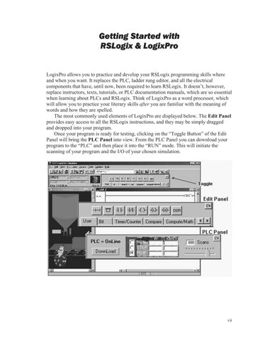
LogixPro allows you to practice and develop your RSLogix programming skills where and when you want. It replaces the PLC, ladder rung editor, and all the electrical components that have, until now, been required to learn RSLogix. It doesn’t, however, replace instructors, texts, tutorials, or PLC documentation manuals, which are so essential when learning about PLCs and RSLogix. Think of LogixPro as a word processor, which will allow you to practice your literary skills after you are familiar with the meaning of words and how they are spelled.
The most commonly used elements of LogixPro are displayed below. The Edit Panel provides easy access to all the RSLogix instructions, and they may be simply dragged and dropped into your program.
Once your program is ready for testing, clicking on the “Toggle Button” of the Edit Panel will bring the PLC Panel into view. From the PLC Panel you can download your program to the “PLC” and then place it into the “RUN” mode. This will initiate the scanning of your program and the I/O of your chosen simulation.

Editing Your Program
If you’re familiar with Windows and how to use a mouse, then you are going to find editing a breeze. Both Instructions and Rungs are selected simply by clicking on them with the left mouse button. Deleting is then just a matter of hitting the DEL, or DELETE, key on your keyboard.
Double-clicking (two quick clicks) with the left mouse button allows you to edit an Instruction’s address while right clicking (with the right mouse button) displays a pop-up menu of related editing commands.
By clicking on an Instruction or Rung with the left mouse button and keeping it held down, you will be able to drag it wherever you please. Let go of it on any of the tiny locating boxes that you will see, and the Instruction or Rung will cling to its new home.
Debugging Your Program
If you take a look at the PLC Panel you’ll notice an adjustable Speed Control. This is not a component of normal PLCs, but is provided with LogixPro so that you may adjust the speed of the simulations to suit your particular computer.

When the simulation is slowed, so is the PLC scanning. You can use this to good effect when trying to debug your program. Set the scan slow enough, and you can easily monitor how your program’s instructions are responding. This capability may not be typical of real PLCs, but for training purposes, you will find that it is an invaluable debugging tool
If you run into problems with the exercises or LogixPro itself, remember that this is still relatively new material and software. Don’t waste too much time trying to figure out some program action that seems amiss. Just e-mail us, and we’ll do our best either to fix or to explain the problem (www.thelearningpit.com).
LogixPro Relay Logic Introductory Lab
RSLogix
Relay Logic Instructions
This exercise is designed to familiarize you with the operation of LogixPro and to step you through the process of creating, editing, and testing simple PLC programs utilizing the Relay Logic Instructions supported by RSLogix.

From the Simulations menu at the top of the LogixPro window, select the I/O Simulator and ensure that the User Instruction Bar shown above is visible.
The program editing window should contain a single rung. This is the End of Program rung and is always the last rung in any program. If this is the only rung visible, then your program is currently empty. If your program is not empty, then click on the File menu entry at the top of the window and select “New” from the drop-down list. A dialog box will appear asking you to select a Processor Type. Just click on “OK” to accept the default TLP LogixPro selection. Now maximize the ProSim-II Simulations window.


The I/O Simulator
The simulator screen shown above should now be in view. For this exercise we will be using the I/O Simulator section, which consists of 32 switches and 32 lights. Two groups of 16 toggle switches are shown connected to 2 input cards of our simulated PLC. Likewise 2 groups of 16 lights are connected to 2 output cards of our PLC. The 2 input cards are addressed as “I:1” and “I:3” while the output cards are addressed “O:2” and “O:4.”
Use your mouse to left click on the various switches, and note the change in the status color of the terminal that the switch is connected to. Move your mouse slowly over a switch, and the mouse cursor should change to a hand symbol, indicating that clicking at this location can alter the state of switch. When you pass the mouse over a switch, a “Tooltip” text box appears and informs you to “Right click to toggle switch type.” Click your right mouse button on a switch, and note how the switch type may be readily changed.
RSLogix Program Creation
Collapse the I/O Simulator screen back to its normal size by clicking on the same (center) button you used to maximize the Simulator's window. You should now be able to see both the simulator and program editing windows again. If you wish, you can adjust the relative size of these windows by dragging the bar that divides them with your mouse. I want you to now enter the following single rung program, which consists of a single Input instruction (XIC—Examine If Closed) and a single Output instruction (OTE— Output Energize). There’s more than one way to accomplish this task, but for now I will outline what I consider to be the most commonly used approach.

First click on the “New Rung” button in the User Instruction Bar. It’s the first button on the very left end of the bar. If you hold the mouse pointer over any of these buttons for a second or two, you should see a short “Tooltip,” which describes the function or name of the instruction that the button represents.

You should now see a new rung added to your program as shown above, and the rung number at the left side of the new rung should be highlighted. Note that the new rung was inserted above the existing End of Program (END) rung. Alternatively you could have dragged (with the left mouse button held down) the New Rung button into the program editing window and dropped it onto one of the locating boxes that would have appeared.

Make sure the rung number 000 is highlighted by left clicking on it. Now left click on the XIC instruction, and it will be added to the right of your highlighted selection. Note that the new XIC instruction is now selected (highlighted). Once again, you could have alternatively dragged and dropped the instruction into the program editing window.

If you accidentally add an instruction, which you wish to remove, just left click on the instruction to select it, and then press the “Del,” or “Delete,” key on your keyboard. Alternatively, you may right click on the instruction and then select “Cut” from the drop-down menu that appears. Left click on the OTE output instruction, and it will be added to the right of your current selection.
Double-click (two quick left mouse button clicks) on the XIC instruction, and a text box should appear which will allow you to enter the address (I:1/0) of the switch we wish to monitor. Use the Backspace key to get rid of the “?” currently in the text box. Once you type in the address, press the Enter key on your keyboard or click anywhere else other than the text box, and the box should close.
Right click on the XIC instruction, and select “Edit Symbol” from the drop-down menu that appears. Another text box will appear where you can type in a name (Switch-0) to associate with this address. As before, pressing Enter or clicking anywhere else will close the box.
Enter the address and symbol for the OTE instruction, and your first RSLogix program will now be complete. Before continuing, however, you should double check that the addresses of your instructions are correct.
Testing your Program
It’s now time to “Download” your program to the PLC. First click on the “Toggle” button at the top right corner of the Edit Panel, which will bring the PLC Panel into view.

Click on the “Download” button to initiate the downloading of your program to the PLC. Once complete, you should click inside the “RUN” option selection circle to start the PLC scanning.
Enlarge the ProSim Simulations window so that you can see both the switches and lamps, by dragging the bar that separates the Simulations and Program Editing windows to the right with your mouse. Now click on switch I:1/00 in the simulator, and if all is well, lamp O:2/00 should illuminate.
Toggle the Switch On and Off a number of times, and note the change in value indicated in the PLC Panel’s status boxes that are being updated constantly as the PLC scans. Try placing the PLC back into the “PGM” mode, and then toggle the simulator’s switch a few times, and note the result. Place the PLC back into the “RUN” mode, and the scan should resume.
We are usually told to think of the XIC instruction as an electrical contact that allows electrical flow to pass when an external switch is closed. We are then told that the OTE will energize if the flow is allowed to get through to it. In fact the XIC is a conditional instruction, which tests any bit that we address for truth or a 1.
Editing your Program
Click on the “Toggle” button of the PLC Panel, which will put the PLC into the PGM mode and bring the Edit Panel back into view.
Now add a second rung to your program as shown below. This time instead of entering the addresses as you did before, try dragging the appropriate address which is displayed in the I/O Simulator and dropping it onto the instruction.
Note that the XIO instruction, which tests for zero or false, has its address highlighted in yellow. This indicates that the instruction is true, which in the case of an XIO means that the bit addressed is currently a zero or false.

Try moving instructions from rung to rung by holding the left mouse button down while over an instruction, and then while keeping the mouse button down, move the mouse (and instruction) to a new location. Try doing the same with complete rungs by dragging the box at the left end of the rung and dropping it in a new location.
Once you feel comfortable with dragging and dropping, ensure that your program once again looks like the one pictured above. Now download your program to the PLC, and place the PLC into the RUN mode. Toggle both Switch-0 and Switch-1 on and off a number of times, and observe the effects this has on the lamps. Ensure that you are satisfied with the operation of your program before proceeding further.


