STRUCTURE MARCH 2026
NCSEA | CASE | SEI
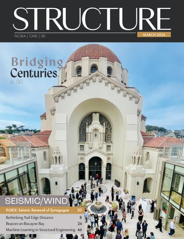
Bridging Centuries p. 30
SEISMIC/WIND INSIDE: Seismic Renewal of Synagogue
30
Rethinking Nail Edge Distance 8 Beacon on Biscayne Bay 24 Machine Learning in Structural Engineering 46
STRUCTURE MARCH 2026
NCSEA | CASE | SEI
Bridging Centuries p. 30
SEISMIC/WIND INSIDE: Seismic Renewal of Synagogue
30
Rethinking Nail Edge Distance 8 Beacon on Biscayne Bay 24 Machine Learning in Structural Engineering 46