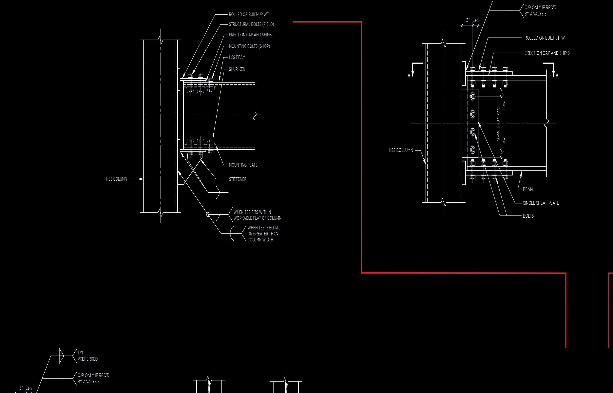
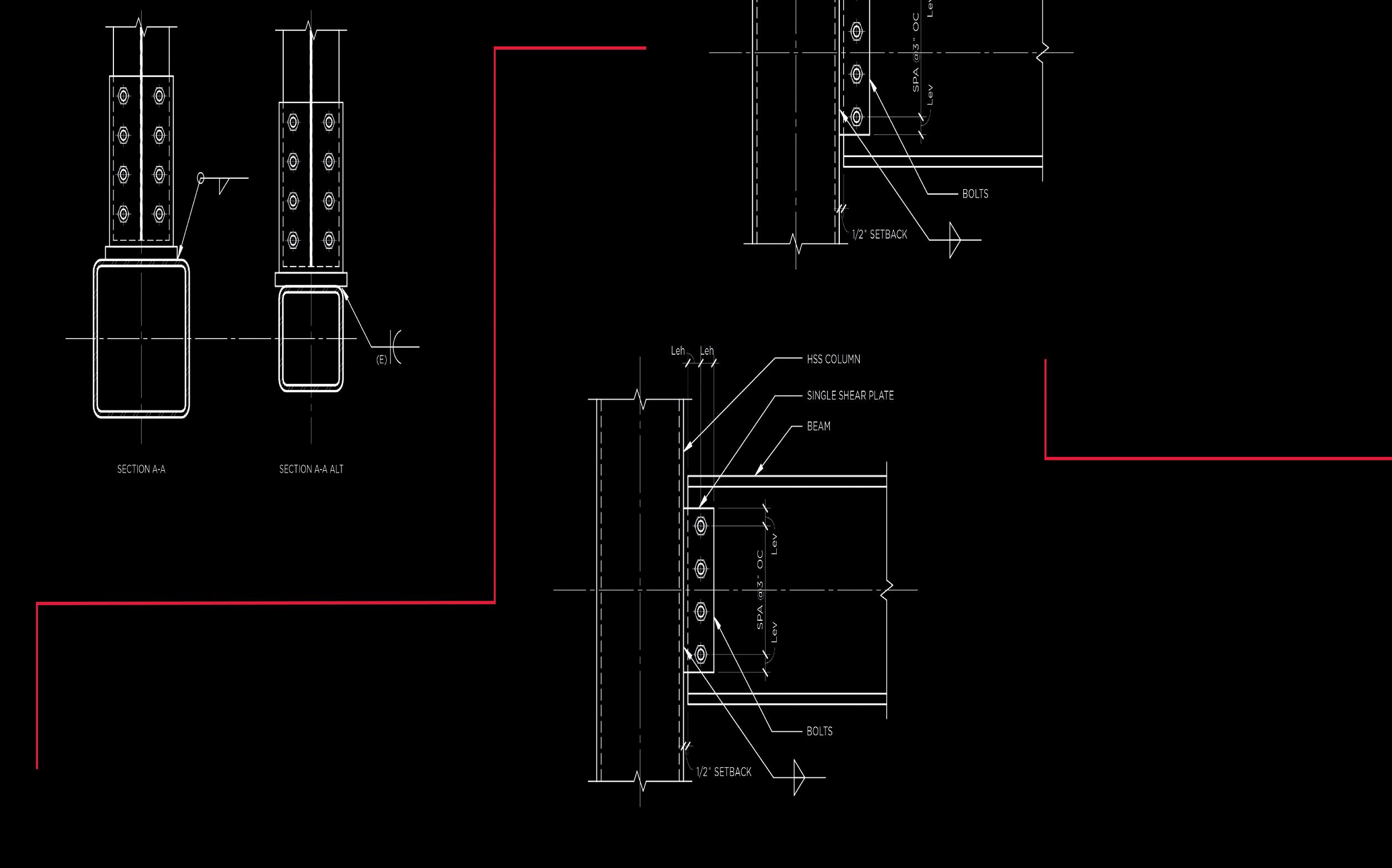
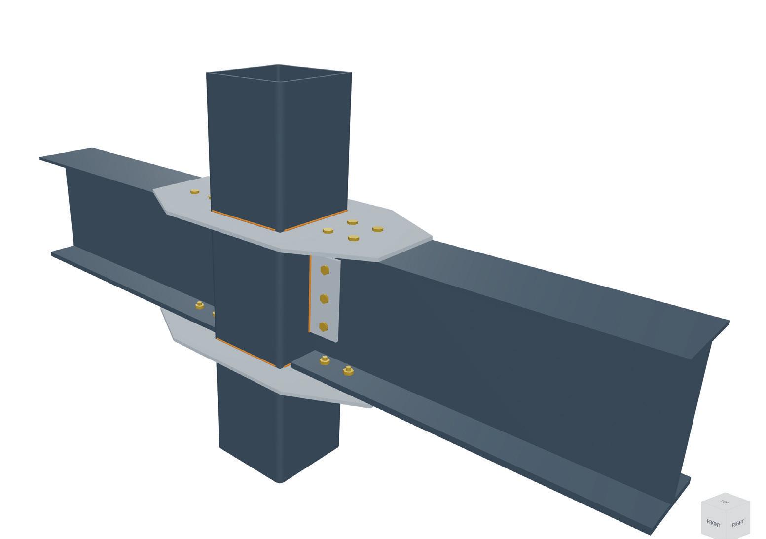
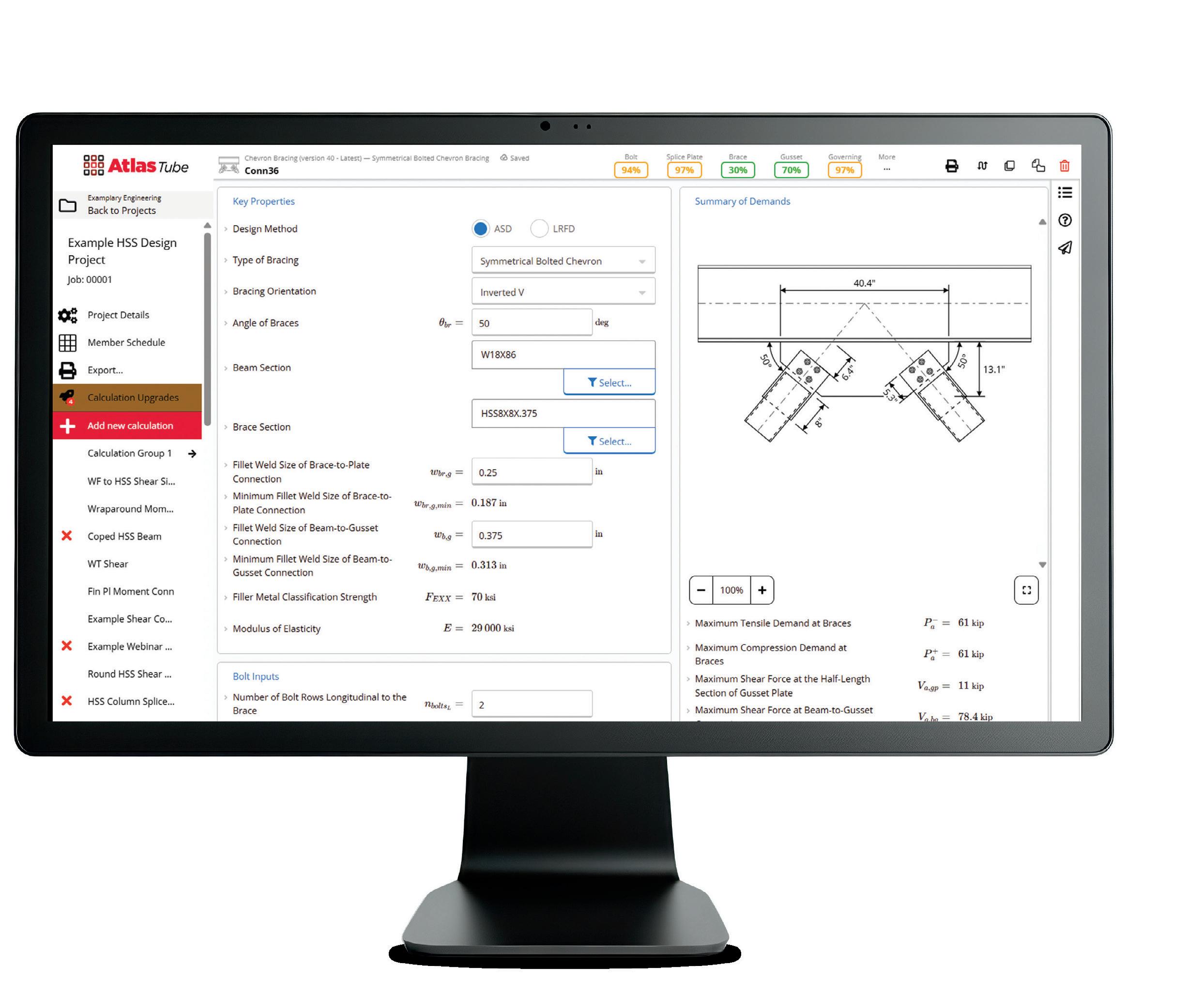
Now with 150+ typical details and calculators for easier, fabrication-friendly HSS connections.
Join 3,200+ engineers and fabricators using this indispensable and complimentary online resource, now including seismic OMF and R=3 system checks, additional diagram views, auto-determined truss connection type and more. Atlas Tube’s HSS Connections Hub streamlines workflows, saves time and helps teams move beyond convention to leverage the full potential of HSS. atlastube.com/hub-more
WORKFLOW EASE.
Atlas Tube’s HSS Connections Hub™ continues to evolve with dozens of recent updates and over 150 connections for AISC and CISC standards.
Welcome to a world of efficient HSS connection design.
No more developing and maintaining custom spreadsheets. Teams can streamline process and enhance collaboration directly on the HSS Connections Hub. Engineers quickly create HSS connection calculations, and fabricators get connection designs that meet requirements without all the back-and-forth revisions.
What’s New, June 2026
• Shear capacity in HSS to HSS splice connections
o Apply and check shear loads on splice connections for enhanced safety
• Seismic OMF and R=3 checks
o Automatic SDC determination based on project address and site soil conditions, checks for Ordinary Moment Frames and more
• Additional truss types
o KT - Overlapped circular
o KT - Gapped circular
o KT - Gapped rectangular
o Bolted truss connection (matched)
o Bolted truss connection (stepped)
• Auto-determined truss
o Automatically determine the truss connection type based on geometry and applied loads and calculate capacity based on this type
• Optimized end plate connection
o Enhanced calculations to optimize end plates for concrete-filled HSS columns
• Reversible loading option
o Toggle allowing reversible loading on bracing templates
• Bulk import from Excel and upload
o Import your connection requirements using Excel, and the HSS Connections Hub will pre-populate the details
• More diagram views
o Top-down views for more clarity and a sneak peek of 3D views
• Axial loads in shear connections
o Apply axial loads to shear connections
• Composite column design
o New calculators for concrete-filled HSS columns, including axial, bending, shear and deflection checks.
• Additional CAST CONNEX® options
o More ways to design with cast steel connections
Put the HSS Connections Hub to work for you.
• Access a growing library of HSS connection calculators and fabrication-friendly typical HSS details.
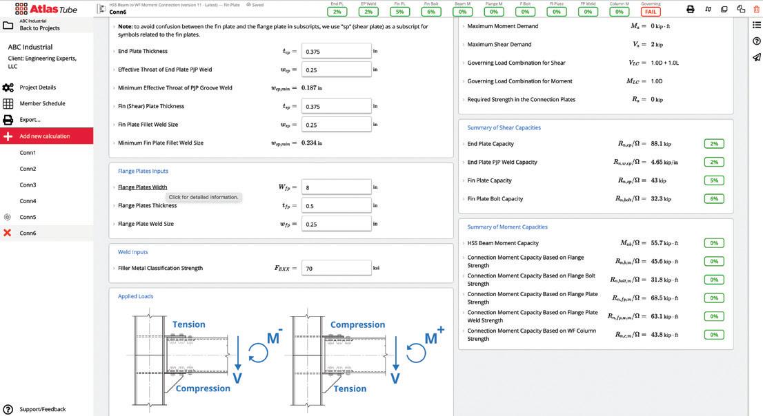
• Hub calculators automate and confirm connection designs in real-time.
Shuriken® Better Bolted Connections
Eliminate field-welding with bolt-and-go ease. More Sizes. More connections.
All Shuriken-enabled calculations are identified in the HSS Connections Hub. Look for the Shuriken icon.
• Clear and concise results indicate whether the designed connection is efficient and meets specified requirements.
• Full transparency: Review and verify your calculations against specific code references with a simple click.
• Download or share detailed reports and connection drawings, including dimensions, bolt sizes and other relevant information for easy communication with fabricators.
• Request support from Atlas Tube’s engineering experts on your project.
Sign up today and start using the HSS Connections Hub. connectionshub.atlastube.com
HSS Connections Hub video demo
STRUCTURE
CIRCULATION
subscriptions@structuremag.org
EDITORIAL BOARD
Chair John A. Dal Pino, S.E. Claremont Engineers Inc., Oakland, CA chair@STRUCTUREmag.org
Kevin Adamson, PE Structural Focus, Gardena, CA
Marshall Carman, PE, SE Schaefer, Cincinnati, Ohio
Erin Conaway, PE AISC, Littleton, CO
Sarah Evans, PE Walter P Moore, Houston, TX
Steven Judd
Interstate Brick, West Jordan, Utah, and H.C. Muddox, Sacramento, California
Linda M. Kaplan, PE Pennoni, Pittsburgh, PA
Publication of any article, image, or advertisement in STRUCTURE® magazine does not constitute endorsement by NCSEA, CASE, SEI, the Publisher, or the Editorial Board. Authors, contributors, and advertisers retain sole responsibility for the content of their submissions. STRUCTURE magazine is not a peer-reviewed publication. Readers are encouraged to do their due diligence through personal research on topics.
By Songtao Liao, Benjamin Pimentel, Matthew Segerman, and Yu Huang
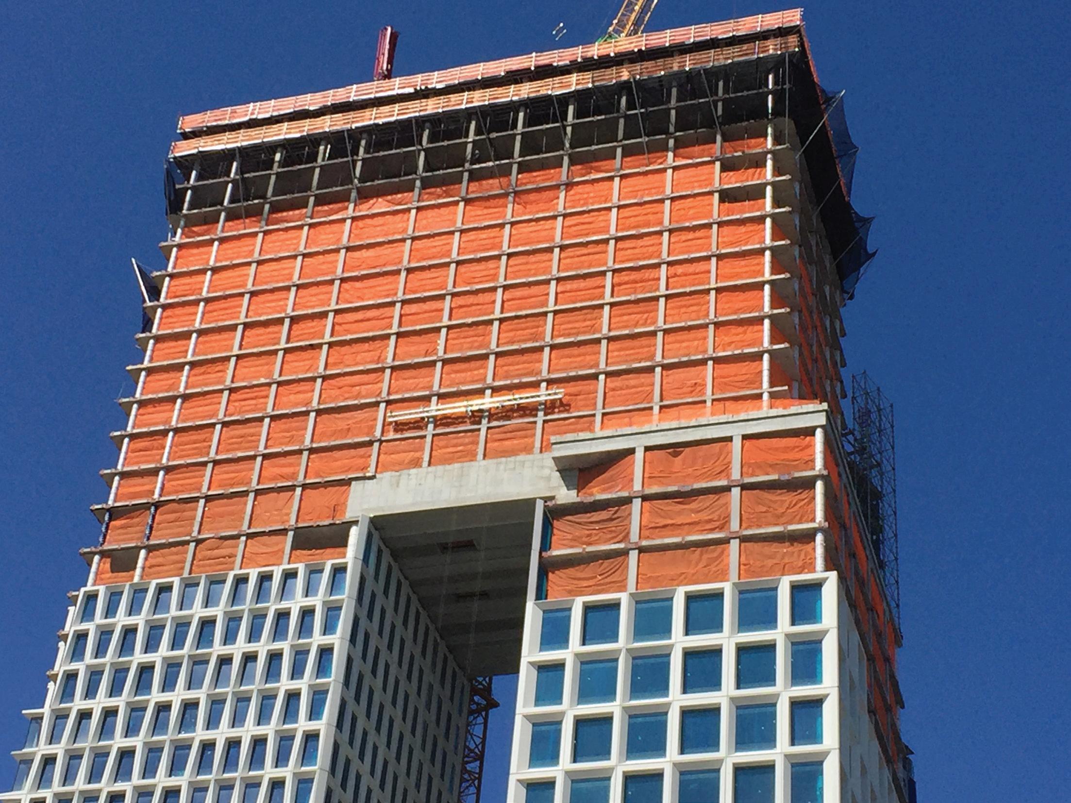
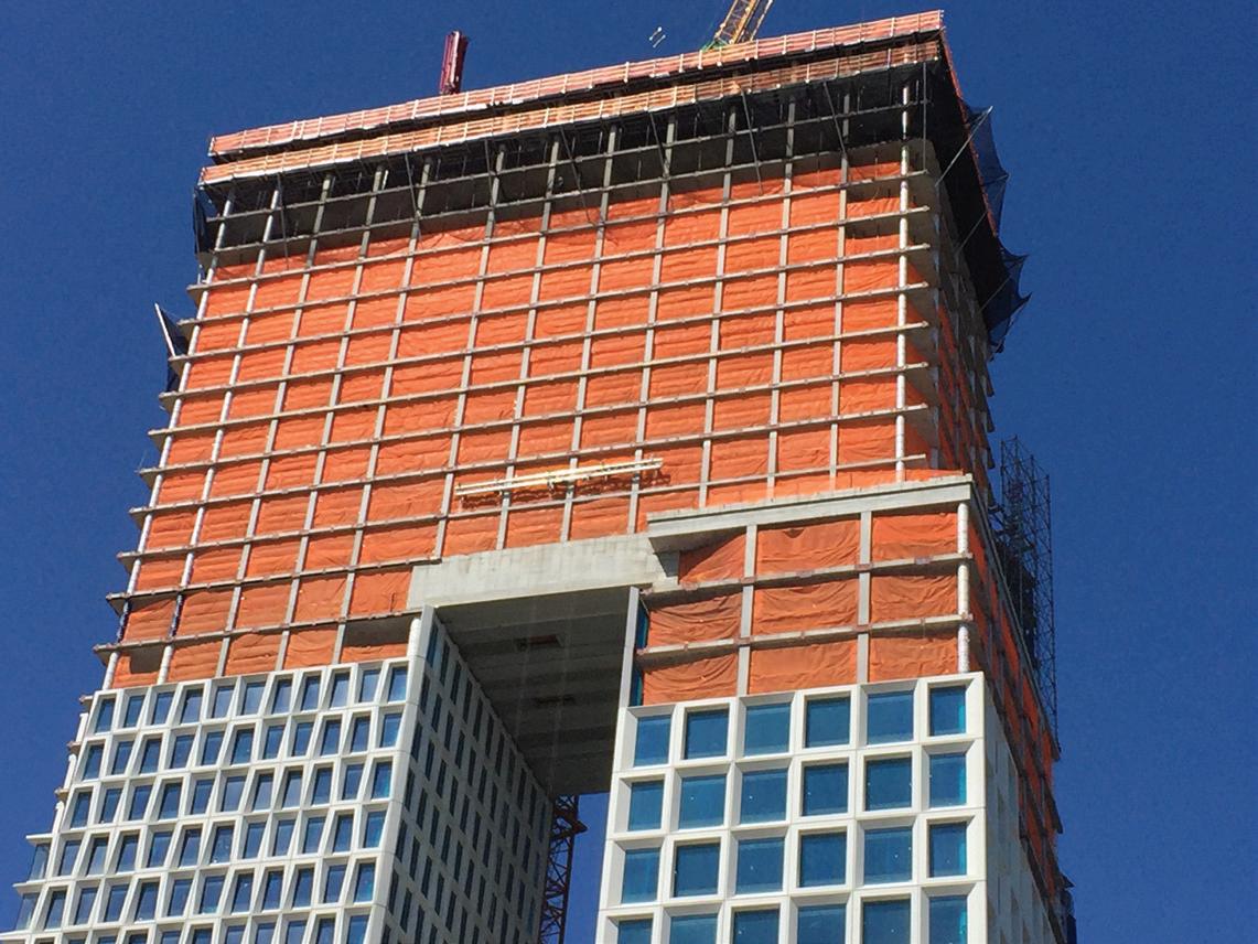
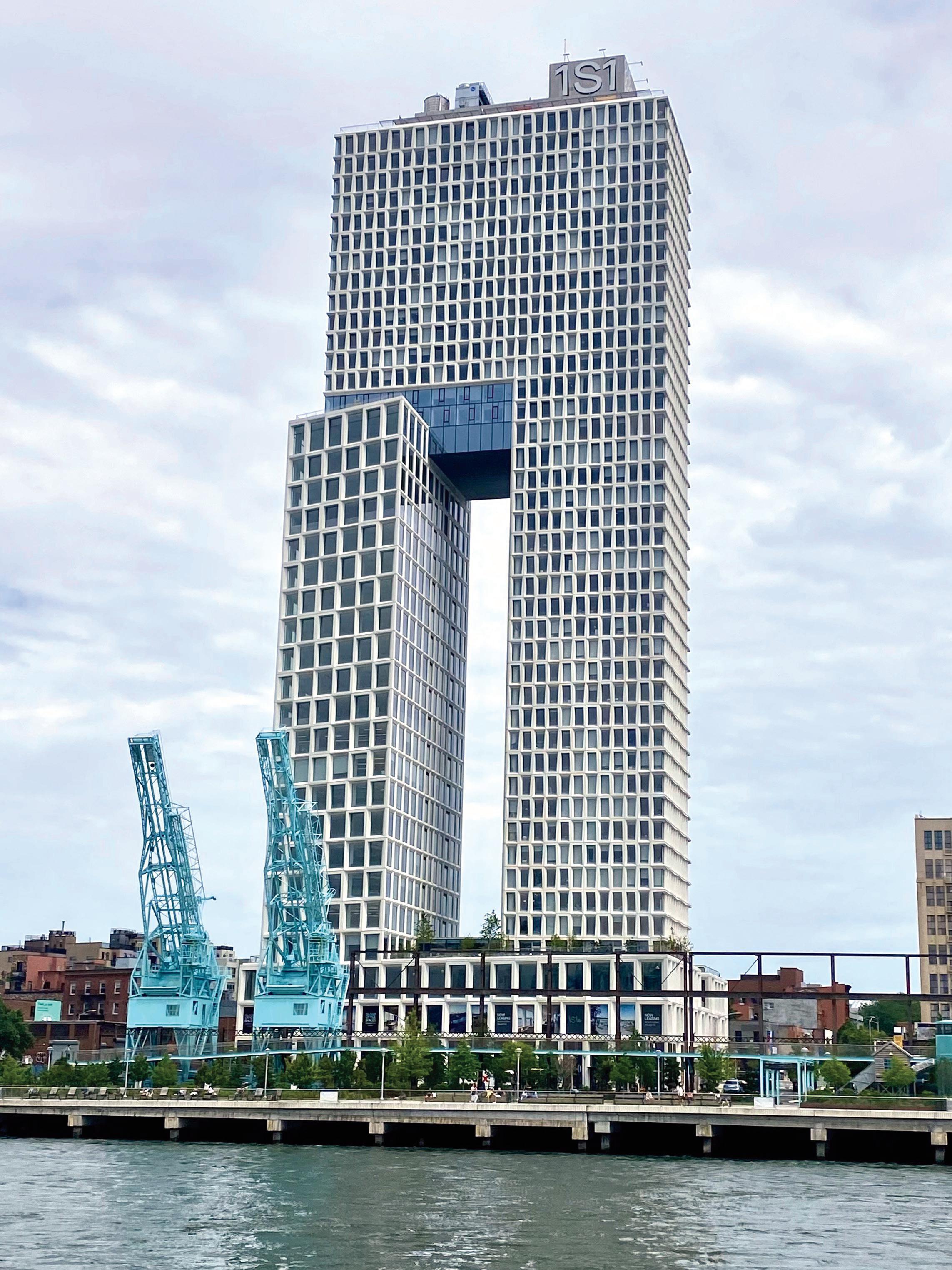
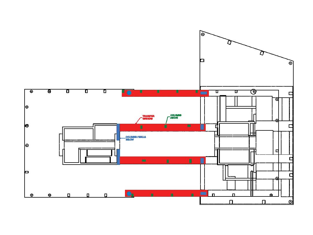
One South First is an interconnected twin-tower high-rise enabled by innovative structural and formwork solutions.
FEATURES
TRANSFORMING HISTORIC
ST. JOHN’S TERMINAL INTO GOOGLE’S NYC HQ
26
By Stephanie Berrios, PE
Using structural bridge design principles, the retrofit enabled a vertical expansion adding nine stories above the original structure.
PINNACLE ON PEACHTREE
By Susendar Muthukumar, PhD, SE, and Daniel Traub, SE
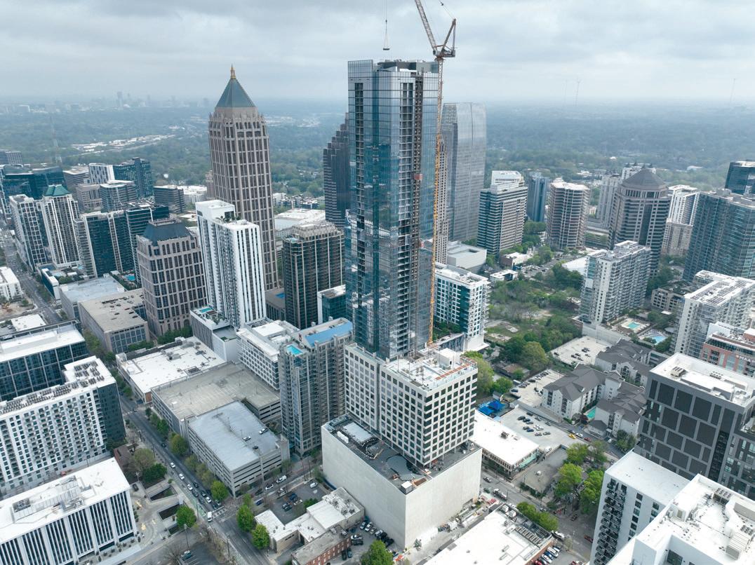
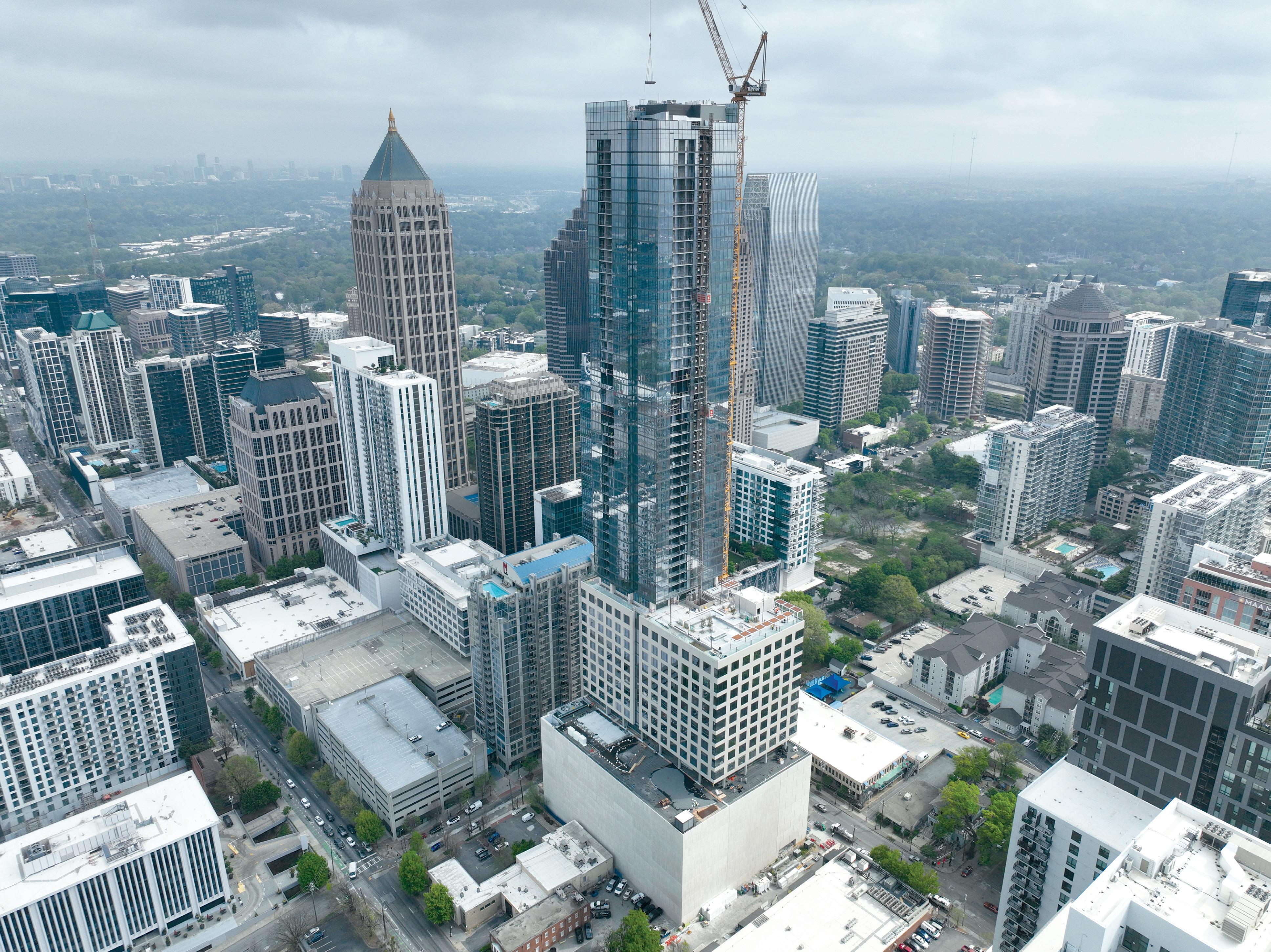
Atlanta’s new 60-story tower soars into the skyline.
46
WARP 10: STRUCTURAL DESIGN OF A CGMP MANUFACTURING FACILITY USING MASS TIMBER
32
By Paul Constantini, PE, SE (AZ, GA, ID, IL, NV) and Taryn Napolitano, PE
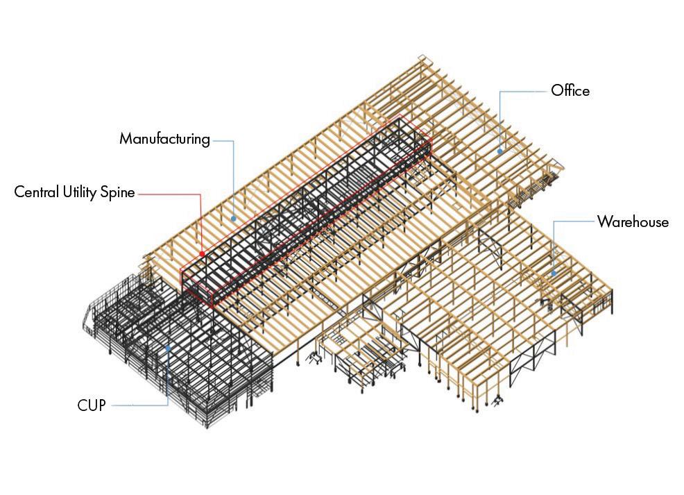
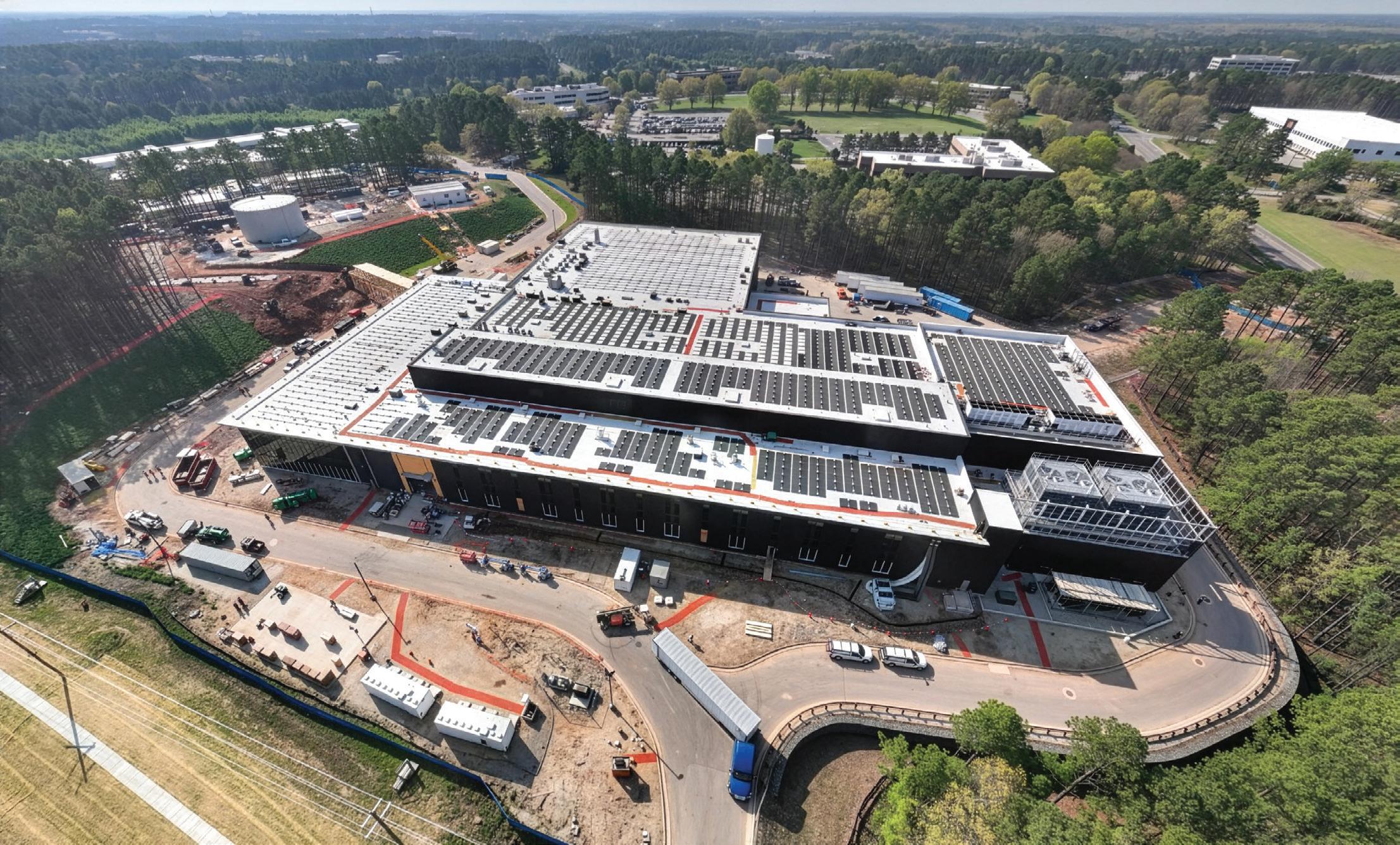
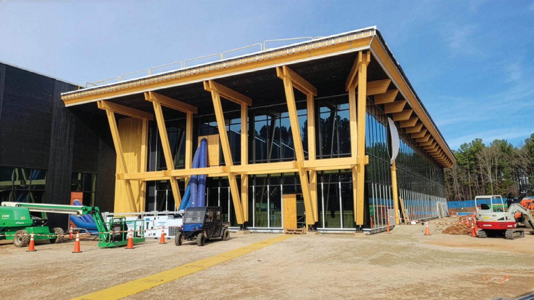
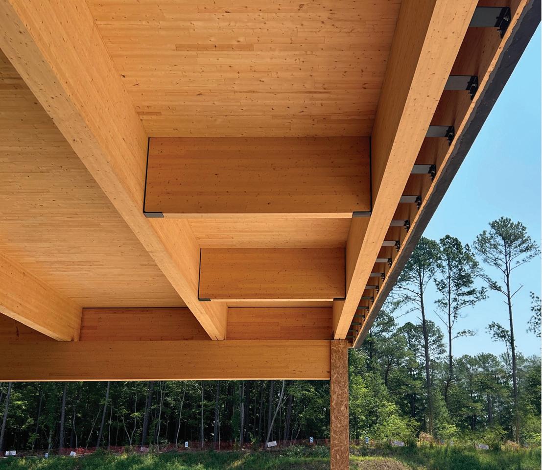
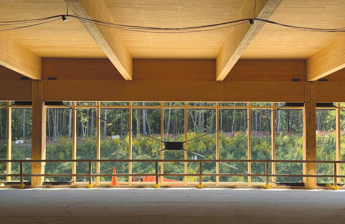
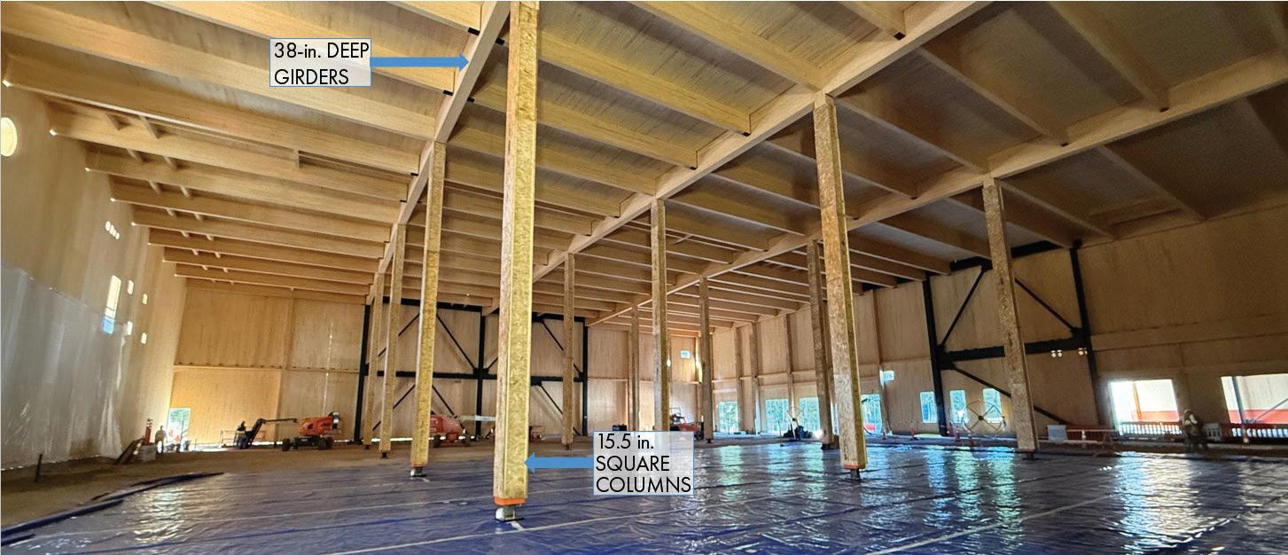
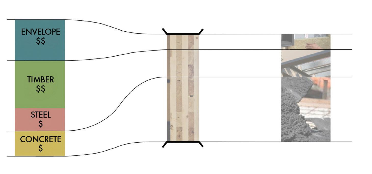
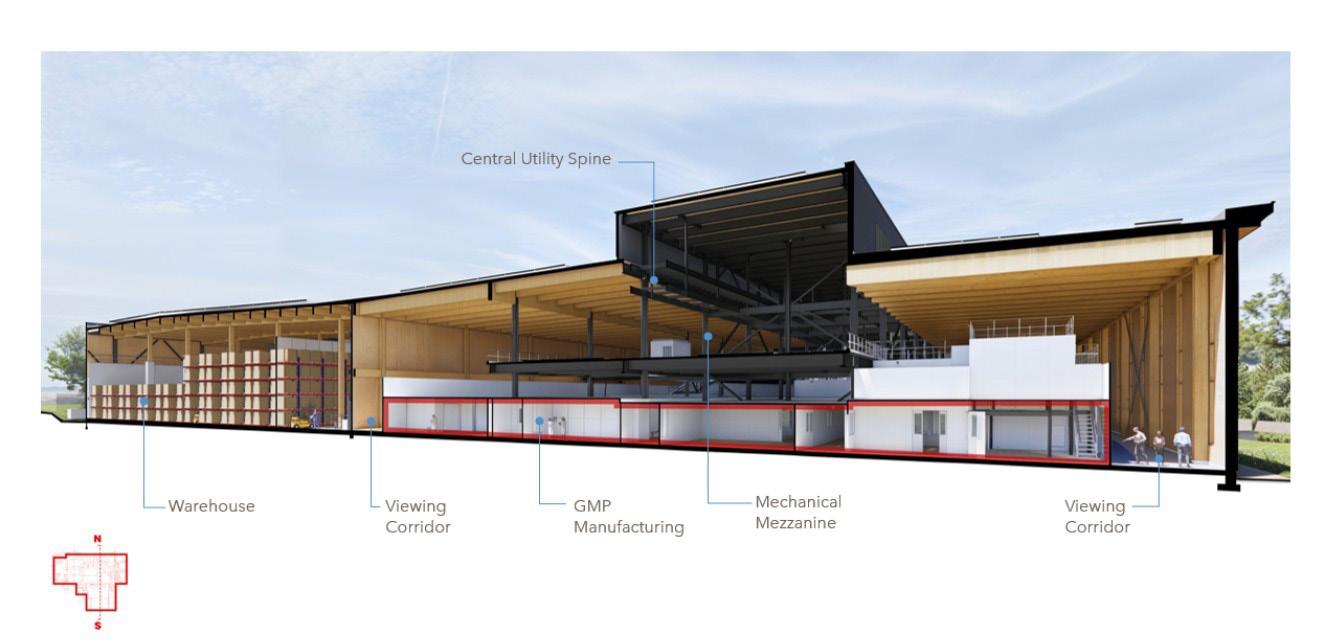
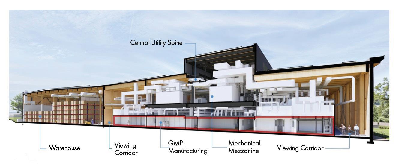
While the United Therapeutics' WARP10 project does not bend space and time, it does aim to achieve something unprecedented in the life sciences sector: to realize a Current Good Manufacturing Practices (cGMP) pharmaceutical manufacturing plant built largely from mass timber and designed to approach zero carbon.
STRUCTURAL FLEX: HOW ONE GIRDER DOES THE HEAVY LIFTING
By Yavor Cekov, PE, Kara Hartleib, PE, and Andrew Zucker, PE
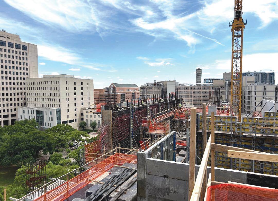
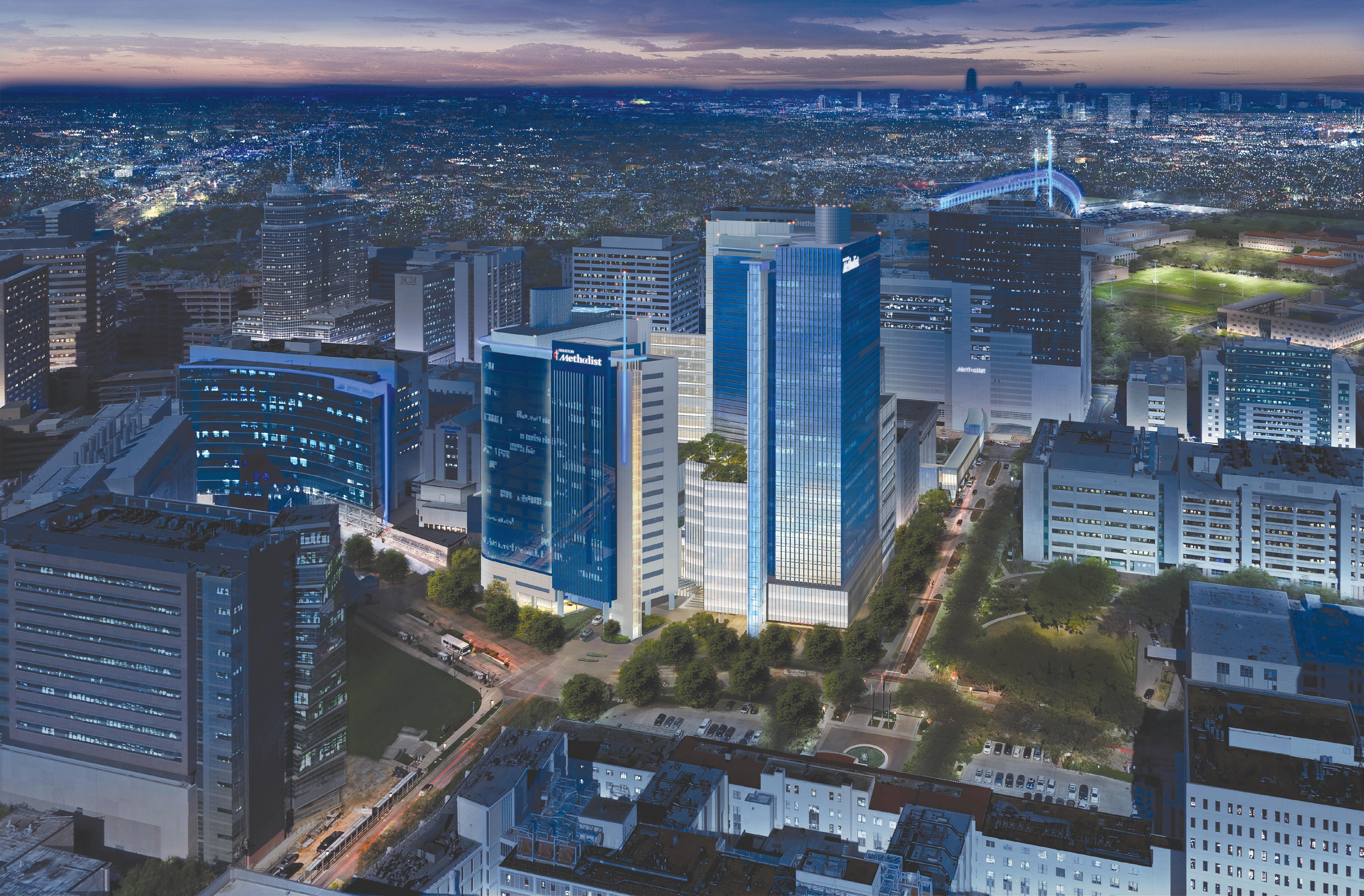
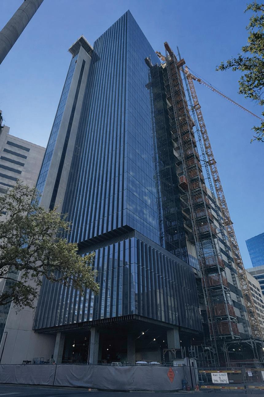
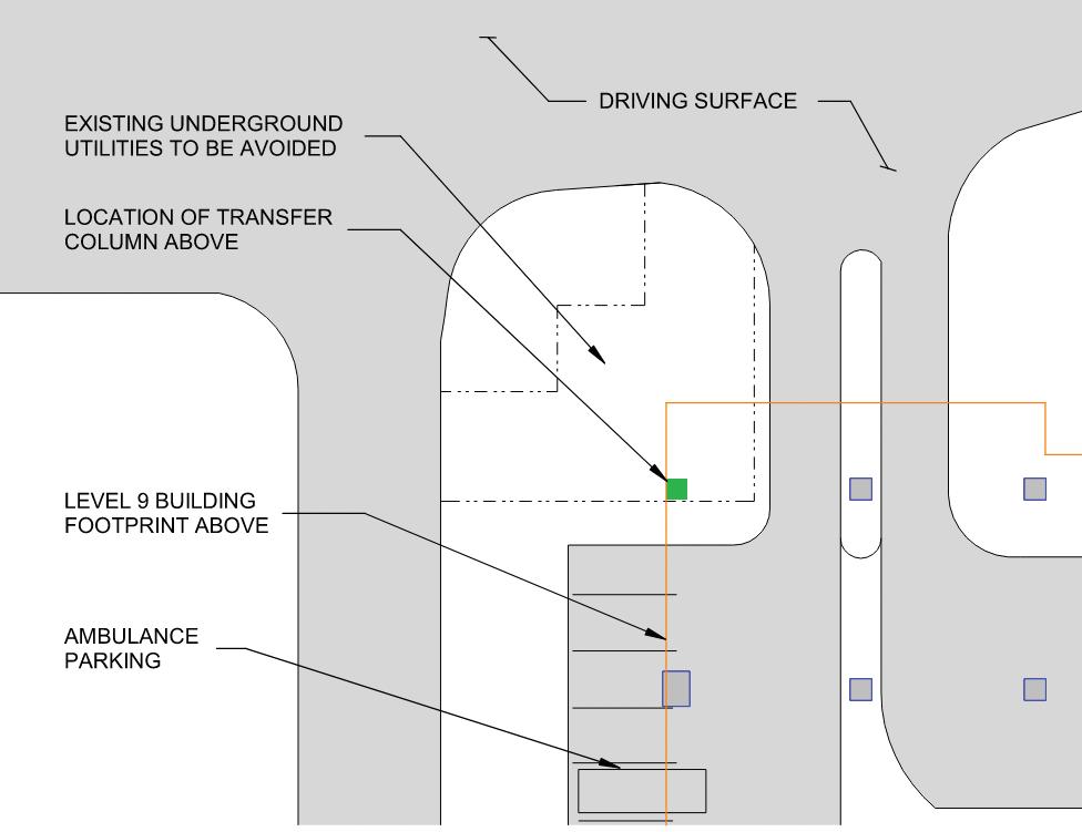
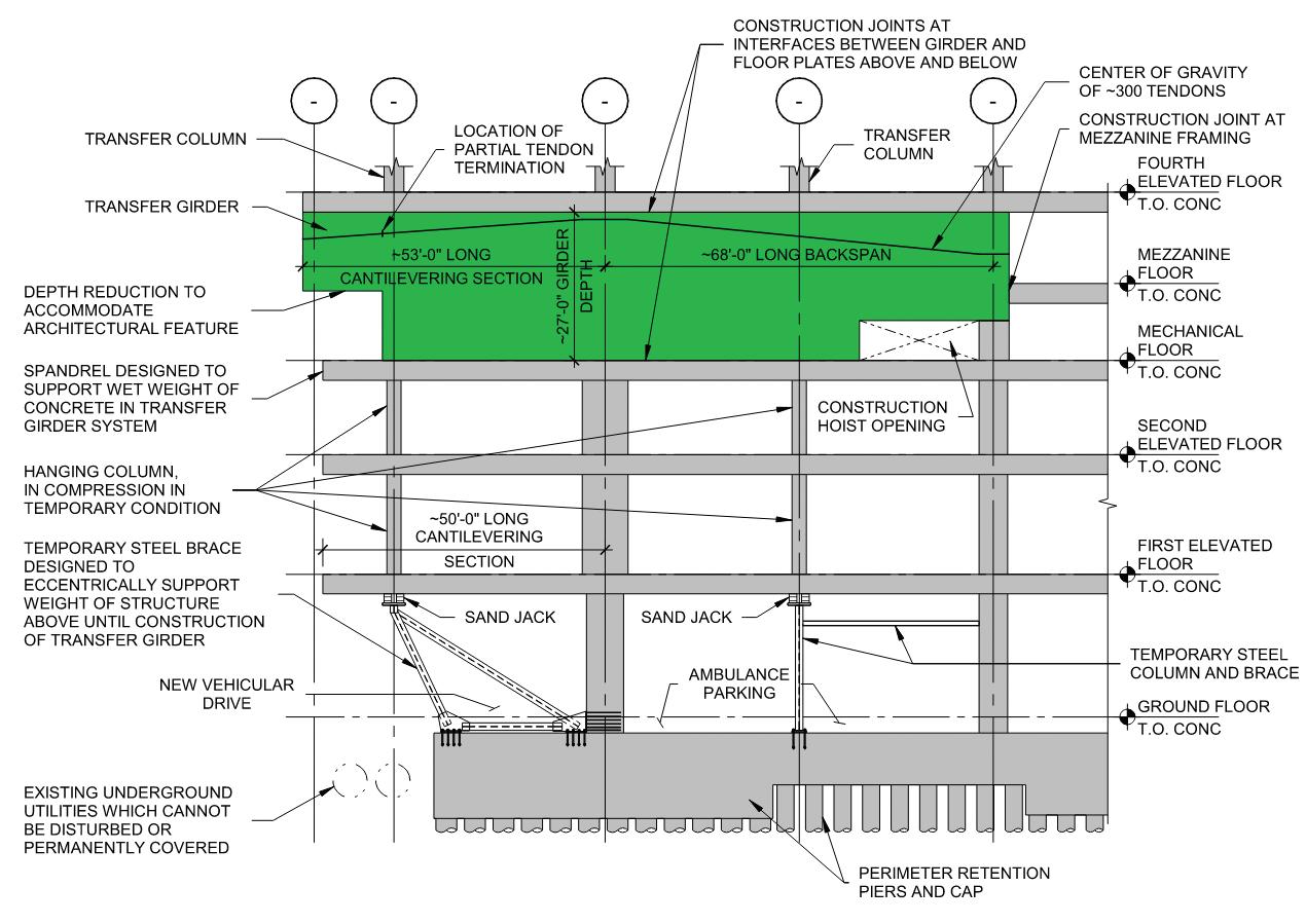
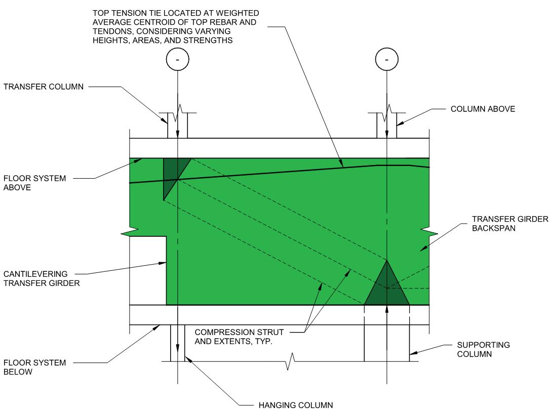
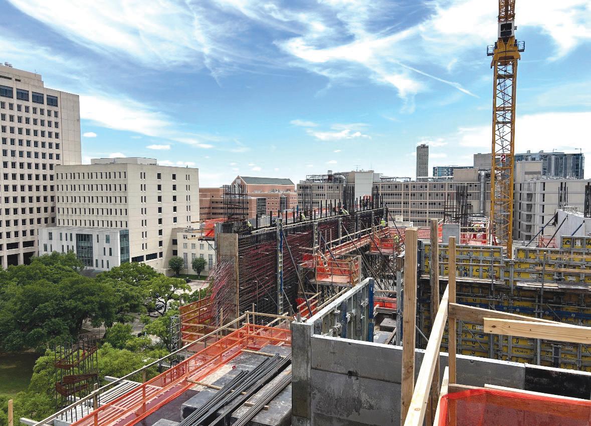
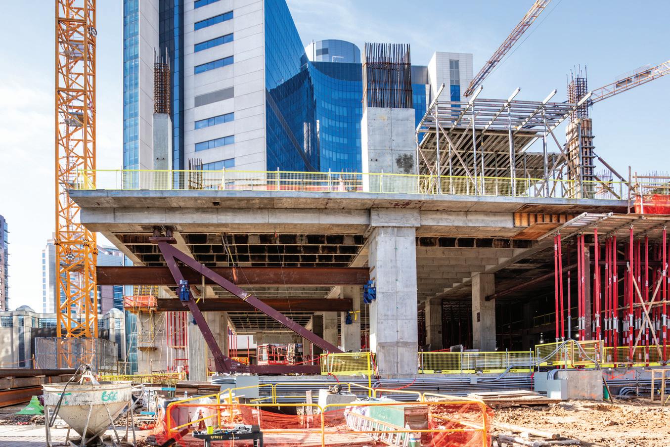
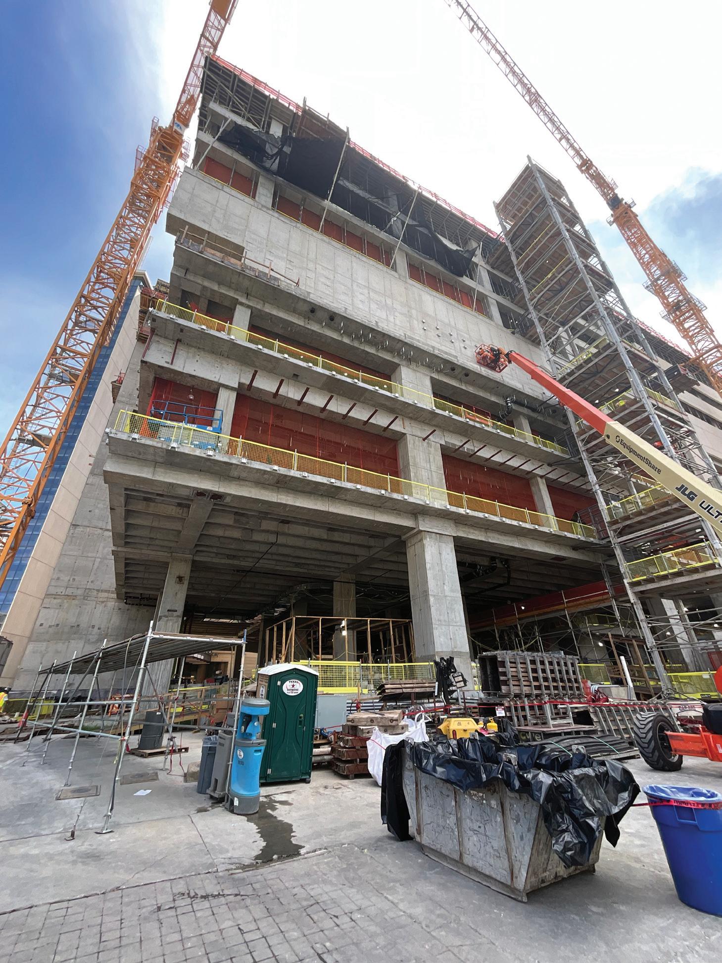
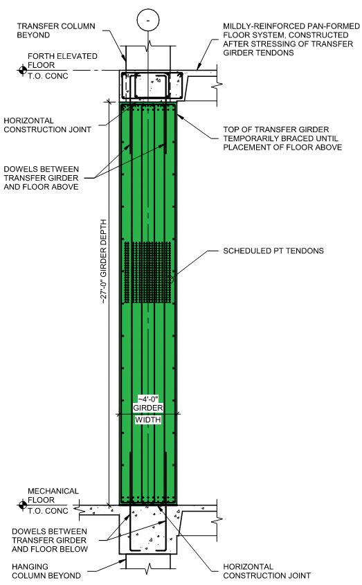
A cantilevering transfer girder helps the corner of Houston Methodist Hospital’s new Centennial Tower float over the ambulance drive and underground utilities. 52
Kevin Aswegan,
Sudarshan C. Kasera,
John A. Dal Pino,
CONNECTION IS CRITICAL
COMPLEX ASSEMBLIES
LEAVE ZERO MARGIN FOR ERROR. DEWALT® DRIL-FLEX® AND TAP-FLEX® STRUCTURAL SCREWS DELIVER THE STRENGTH AND DUCTILITY YOUR CURTAIN WALL SYSTEM DEMANDS.
THE FIRST * AND ONLY** ICC-ES APPROVED SELF-DRILLING TAPPING SCREWS USED IN ALUMINUM.
The Future Is Now: Performance-Based Design
By Kevin Aswegan, PE, SE, F.SEI
In 2019, I read and was inspired by the structural efficiencies and improvements described in Don Dusenberry’s editorial in this publication titled “Performance-Based Design Is the Future.” Here we are, seven years later, and that future is now.
Performance-based design (PBD) is more relevant and critical today than it has ever been. This is evidenced by the Structural Engineering Institute’s (SEI’s) recent decision to establish PBD as one of four new “Focus Initiatives” (alongside Education and Leadership, Young Professionals, and SE 2050) to help prioritize resources and activities for the immediate future.
SEI selected PBD as a Focus Initiative because of its proven ability to improve design, reduce material quantities, and streamline construction offering a solution for some of the most significant challenges society faces related to sustainability, cost of construction, and affordable housing.
What Has Transpired?
Since 2019, PBD has increased in popularity and impact. From its origin with design firms on the west coast of the United States in the 1990s as a way to design better structures in seismic zones, performance-based seismic design (PBSD) has expanded around the world. Because it is recognized as state-of-the-art design methodology, it is even being employed in areas of low or moderate seismic hazard. In many cities, PBD is no longer considered an exotic design approach, but rather the standard of care for tall or unique buildings.
The expansion of PBD principles to other hazards beyond earthquakes has also gained traction. With the publication of ASCE’s Prestandard for Performance-Based Wind Design (PBWD) in 2019, and an updated version in 2023, the first project designed and built using PBWD principles was recently completed: ATX Tower in Austin, Texas. Due to the direct consideration of nonlinear structural behavior, the design resulted in significant cost savings for the project as compared to prescriptive design.
Creativity Shines
Prescriptive code-based design has its advantages and disadvantages. Its advantages include
simplicity, uniformity, broad applicability, and ease of implementation; however, those advantages come with inherent drawbacks. Because prescriptive design must be capable of being written down in “mandatory language” in a building code, it is necessarily limited. It cannot address all cases and therefore must be a simplification and approximation of reality.
On the other hand, PBD flips the narrative. Rather than defining a precise step-by-step process, it creates a framework. This framework puts the end first, starting with defining the intended performance objectives for a given hazard (e.g. collapse prevention or reoccupancy) and works backwards from there. By reframing the problem in this way, it allows and even encourages structural engineers to get creative. PBD creates the opportunity for structural engineers to do the following:
• Extend prescriptive structural systems beyond their rigid code limitations. A common example is the Special Reinforced Concrete Shear Wall system, which for earthquake design is limited to 160 feet (or 240 feet with certain regularity requirements) for most high seismic sites. PBSD has been used on hundreds of tall buildings to demonstrate that the structures performed as intended by the building code without conforming to every prescriptive requirement.
• Introduce new structural systems. Opportunities for innovation abound with PBD, which creates a framework to introduce new systems or construction techniques like SpeedCore into the industry.
• Enhanced performance targets. PBD provides a detailed and comprehensive understanding of the performance of engineering designs. With input from stakeholders (e.g. architects, owners, and the public), this allows us to set enhanced performance targets that may exceed the building code. This is a common discussion with “long term” building owners such as universities, hospitals, and government agencies who may desire structural performance better than “code minimum.”
Shift in Mindset
PBD is sometimes misunderstood as a synonym for “advanced analysis” or “nonlinear
modeling.” While PBD may include advanced design techniques as part of the process, those techniques are merely tools rather than being fundamental.
A mindset shift is needed within the profession to embrace probabilistic thinking and move beyond binary pass/fail design approaches. Instead, we must arm our clients with information to make risk-informed decisions. PBD can be best summarized as a shift in focus from compliance to intent. In other words, rather than ticking boxes within a checklist of building code requirements, engineers should aim to explicitly prove that a design achieves the intent of the building code.
Let’s Be Leaders
As Dusenberry succinctly warned in his 2019 editorial, “We are evolving into masters of the Code, who add value by being able to navigate the complexity of prescriptive provisions rapidly, rather than by developing creative and innovative solutions to multi-faceted problems.” This is a danger collectively to our profession, made much more critical by the advent of Artificial Intelligence, which will inevitably soon surpass structural engineers with ability to instantly recall every aspect of the building code and perform basic engineering tasks.
PBD presents an opportunity to bring increased value to society as thought leaders rather than facilitators. Engineers are key to solving many of the industry’s biggest challenges by reducing project cost, building structures faster, and tailoring performance objectives to client needs. As structural engineers, we must embrace this opportunity for leadership, not only because it is what is best for society, but it is also what is best for our profession. ■
Kevin Aswegan, PE, SE, is a Senior Principal at Magnusson Klemencic Associates, a structural and civil engineering firm headquartered in Seattle. Kevin serves as the Chair of the SEI Advancement of Performance-Based Design Committee.
structural DESIGN
Unevenly Loaded Welds Revisited
Inelastic analysis can be used to identify whether action is needed to mitigate the effects of uneven loading and help determine the best mitigation strategy.
By Mark Denavit
Welding expert Duane Miller wrote an excellent pair of articles for the February and March 2024 issues of STRUCTURE Magazine. The articles described 10 conditions where welds can experience uneven loading. These conditions can be problematic if not avoided or given special attention in design. The common assumption that applied loads cause uniform stresses in a weld does not apply for these conditions. However, what if you are using a design approach that never makes such an assumption? Connection design by inelastic
Ten Most Frequently Encountered Conditions Involving Unevenly Loaded Welds
In his 2024 STRUCTURE two-part series on unevenly loaded welds (February and March issues), author Duane Miller summarized the following common conditions encountered.
Condition 1: Unevenly Loaded Because of Bending About the Root of Fillet or PJP Groove Welds
Condition 2: Unevenly Loaded Because of a Single Transverse Weld in an End-Loaded Lap Joint
Condition 3: Unevenly Loaded Because of Short Spacing Between Transverse Welds in End-Loaded Connections
Condition 4: Unevenly Loaded Because of Shear Lag
Condition 5: Unevenly Loaded Because of a Long Weld in an End-Loaded Connection
Condition 6: Unevenly Loaded Because the Weld Group Is Unevenly Loaded
Condition 7: Unevenly Loaded Because the Weld Attaches a Rigid Member to a Flexible Member
Condition 8: Unevenly Loaded Because Transverse Welds Are Combined with Longitudinal Welds
Condition 9: Unevenly Loaded Because the Weld Is Part of a Tubular Connection
Condition 10: Unevenly Loaded Because Welds Are Combined With Bolts or Rivets
analysis, for example using the component-based finite element method (CBFEM) such as implemented in IDEA StatiCa Connection, makes no broad assumptions about the distribution of stress in welds, or any other components. Stresses arise naturally in the analysis based on the stiffness of the various components of the connection. This article walks through each of Miller’s 10 conditions to identify what special attention they require when designing by inelastic analysis.
The first condition is uneven loading because of bending about the root of a fillet or PJP groove weld. The second condition is a single transverse weld in an end-loaded lap joint, where there is potential for uneven loading because of bending about the root if the deflection of the lapped parts is not sufficiently restrained. Modeling of welds varies in inelastic analysis approaches, but in the CBFEM, fillet welds and PJP groove welds are modeled using multi-point constraints and an equivalent weld shell element that approximates the elastoplastic behavior of the weld. An important aspect of this modeling approach is that it results in zero bending stiffness about the root of the weld. As a result, no bending stresses can develop and, for the details shown in Miller’s article, the analysis will not run because the lack of bending stiffness makes the model unstable. However, in some cases, the connection may not rely on the bending stiffness of the weld to be stable, and bending deformations about the root of a weld can develop. Bending deformations should be avoided by inspection of the deflected shape from the analysis model and proper detailing of the connection.
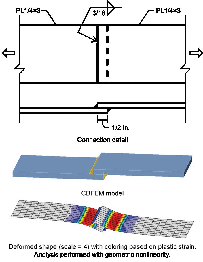
In the third condition, the uneven loading is due to short spacing between transverse welds in end-loaded connections. Using the CBFEM, the spacing has minimal effect on the strength of the welds. Consider the connection shown in Figure 1. Without geometric nonlinearity, the boundary conditions and eccentricity result in significant bending in the plates. Bending is reduced with geometric nonlinearity due to membrane effects, yet the short spacing has no effect on the welds. For very short spacing (e.g., overlap of 1/2 inch), the plates yield, limiting strength, but again the evaluation of the welds is not affected. Ealuating strength by inelastic analysis eliminates the need to check certain limit states captured by the model, but it does not eliminate the need to satisfy detailing requirements such as the requirement in AISC Specification Section J2.2b(f) which prescribes a minimum overlap distance.
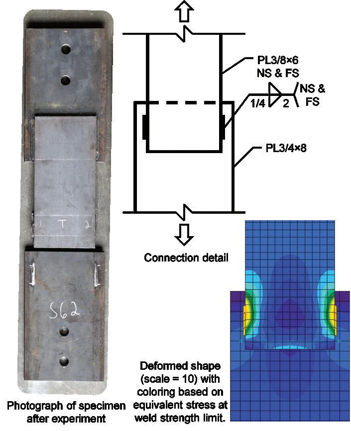
Shear lag is the concern in the fourth condition. While shear lag exists in connections such as the end-loaded lap joint shown in Figure 2, whether shear lag affects the strength of the connection is unclear. CBFEM analyses do not detect any reduction in weld strength due to shear lag for this connection, but neither did a recent series of physical experiments conducted by the author. Nonetheless, just like for the third condition, American Welding Society (AWS) detailing requirements must be satisfied even when assessing strength using inelastic analysis. Specifically, AWS D1.1 Clause 4.9.2 specifies that the length of each fillet weld shall be no less than the perpendicular distance between them if longitudinal fillet welds are used alone in lap joints of end connections of flat bar or plate members.
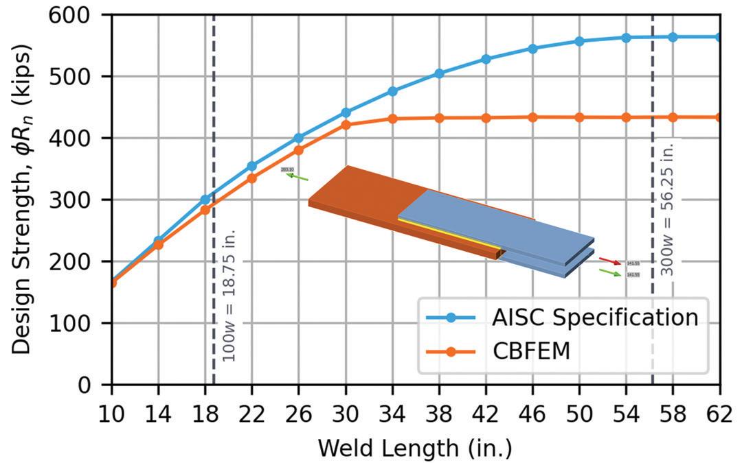
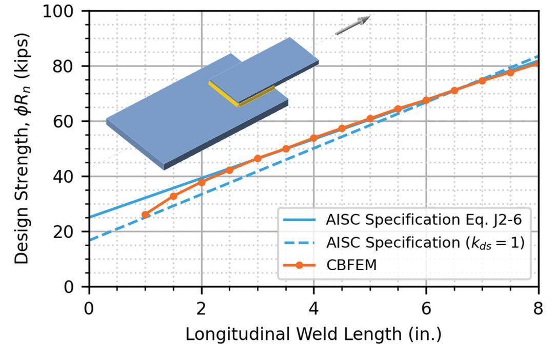
Long welds in end-loaded connections experience uneven loading due to strain compatibility between the connected parts. The stress near the ends of the welds is greater than near the middle with the difference depending on the relative stiffness between the welds and the connected parts. In traditional design, this fifth condition of unevenly loaded weld is addressed by using a reduced effective length for long welds. In design by inelastic analysis, the stiffnesses of the welds and connected parts are modeled explicitly, and strain compatibility is enforced. Thus, the results more accurately capture the effect of uneven loading than the approximate equation. A comparison between the results from CBFEM analyses and traditional design is shown in Figure 3 based on a larger study.
The sixth condition is when the weld group is unevenly, or eccentrically, loaded. In traditional design, this condition is often addressed using the instantaneous center of rotation method via tables in Part 8 of the AISC Manual. The instantaneous center of rotation method is itself a nonlinear analysis method that ensures equilibrium and strain compatibility are satisfied while also incorporating the beneficial effect of the directional strength increase factor. Comparisons between the instantaneous center of rotation method and the CBFEM for bracket plate connections have shown that the CBFEM conservatively captures the uneven loading.
Conditions 7 through 10 feature multiple possible load paths, with
Unevenly loaded welds ... deserve special attention because they can be less efficient than evenly loaded welds and because they violate common assumptions in traditional design approaches.
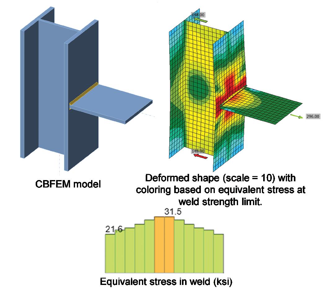
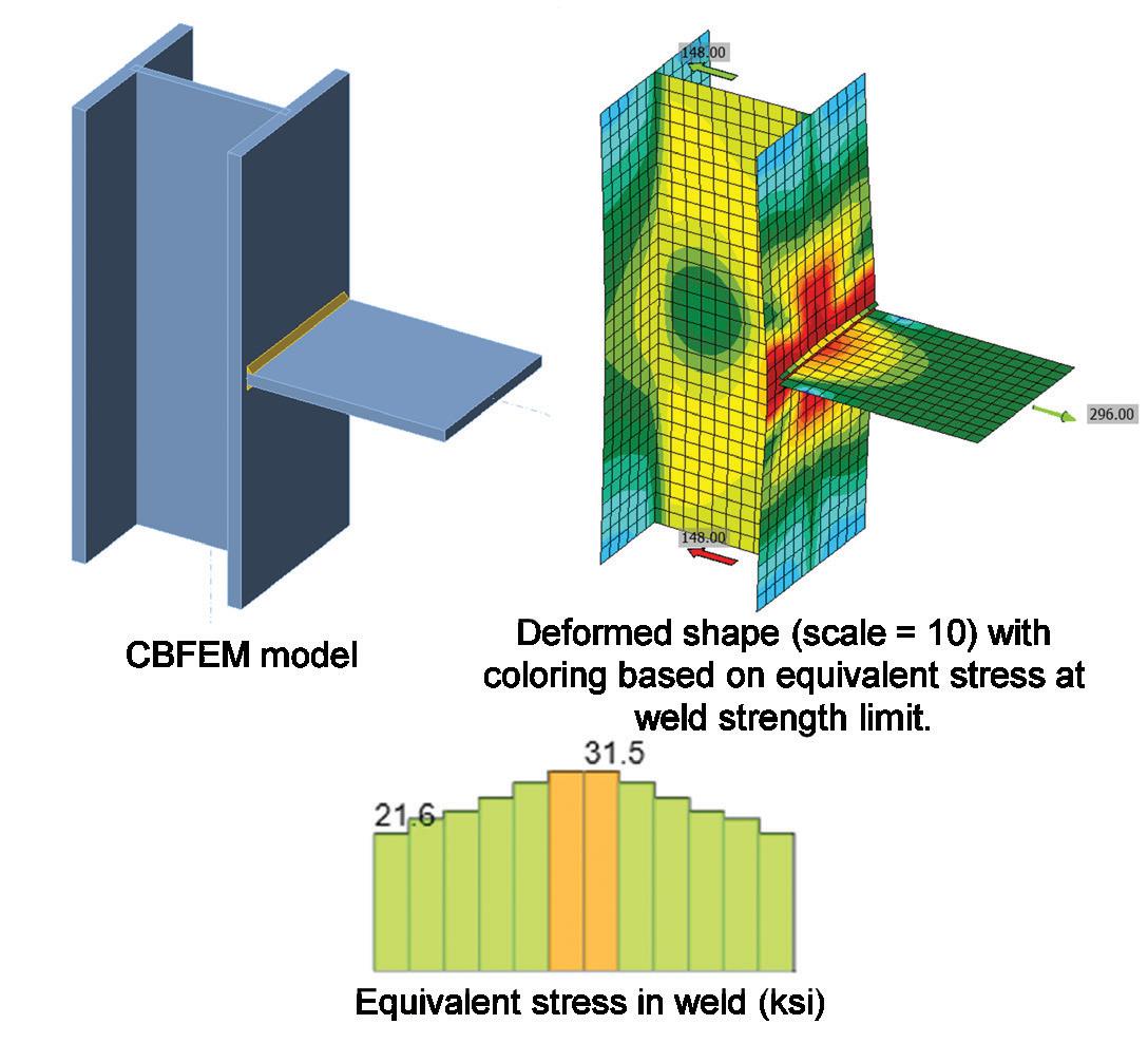
uneven loading arising because some paths are stiffer or stronger than others. Design by inelastic analysis is well suited to properly evaluate these conditions because the stiffness of all components is modeled explicitly and strain compatibility and equilibrium are enforced. Welding a rigid member to a flexible member is the seventh condition. A plate under tension welded across the flange of an I-shaped section such as shown in Figure 4 is a classic example of Condition 7. The weld between the plate and the flange is unevenly loaded because a greater portion of the load is attracted to the stiffer path directly through the flange and into the web. When modeled using the CBFEM, the weld stresses are highest at the web of the I-shaped member. These welds reach their full utilization first, signaling that the strength of the connection has been reached, even when the portions of the weld near the flange tips are not at their full capacity. The ninth condition, welds that are part of a tubular connection, is another example of welding a rigid
Fig. 1. Short spacing between transverse welds in end-loaded connections results in an unevenly loaded weld. (Condition 3)
Fig. 2. Shear lag exists in an end-loaded lap joint but it’s not clear if it affects the strength of the connection. (Condition 4)
Fig. 3. Strength comparison for long end-loaded welded connection (Condition 5)
Fig. 4. A rigid member welded to a flexible member is an example of Condition 7.
member to a flexible member. Again, the CBFEM is able to pick up the uneven loading and compute the utilization of the welds accordingly. In the eighth condition, transverse welds are combined with longitudinal welds and uneven loading occurs because welded connection with transverse welds are stronger but less ductile than similar connections made with longitudinal welds. The AISC Specification provides Equation J2-6 for concentrically loaded weld groups such as this. Even without implementation of this equation, the CBFEM captures the effect well since the underlying behavior is modeled and incorporated in the strength checks (Fig. 5).
The tenth and final condition of uneven loading occurs when welds are combined with bolts or rivets. AISC Specification Section J1.8 allows bolts and welds to be considered as sharing load only in the design of shear connections on a common faying surface where strain compatibility between the bolts and welds is considered. Strength checks for bolts and welds are independent in the CBFEM with no special handling of when bolts and welds share load. Given the explicit modeling of the stiffness of bolts, welds, members, and connecting elements, strain compatibility is always considered in the CBFEM. When bolts and welds share load, the required strength of each is based on their relative stiffness. The result is overall strengths that are similar to those obtained using the approximate method also presented in AISC Specification Section J1.8. However, the CBFEM generally does not prohibit sharing of loads between bolts and welds in tension connections. The user must avoid cases such as this by modeling either bolts or welds in tension connections, even if both are present in the physical connection.
Unevenly loaded welds such as evaluated in Miller’s original articles and revisited here deserve special attention because they can be less efficient than evenly loaded welds and because they violate common assumptions in traditional design approaches. Design by inelastic analysis
Fig. 5. Strength comparison for C-shaped weld group with longitudinal and transverse welds (Condition 8).
provides a path forward for these welds because well-defined analysis models never assume that welds are evenly loaded. Furthermore, inelastic analysis can be used to identify if action is needed to mitigate the effects of uneven loading, and, where necessary, help determine the best mitigation strategy. ■
Full references are included in the online version of the article at
Mark Denavit is an associate professor in the Department of Civil and Environmental Engineering at the University of Tennessee, Knoxville.
“The
— Lenard Tran SE, PE - Structural Engineer of MDEP
Engineering Concealment Telecommunication Towers
Designing
cell towers that are hidden in plain sight balances aesthetics and structural performance.
By Sudarshan C. Kasera, PE, PMP
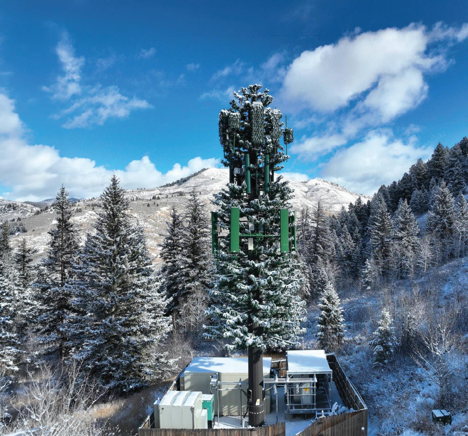
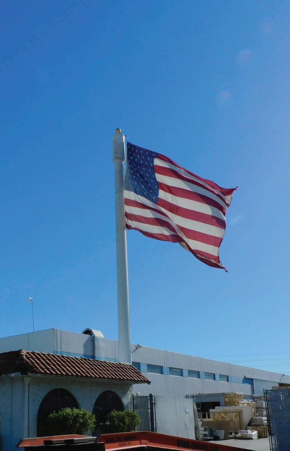
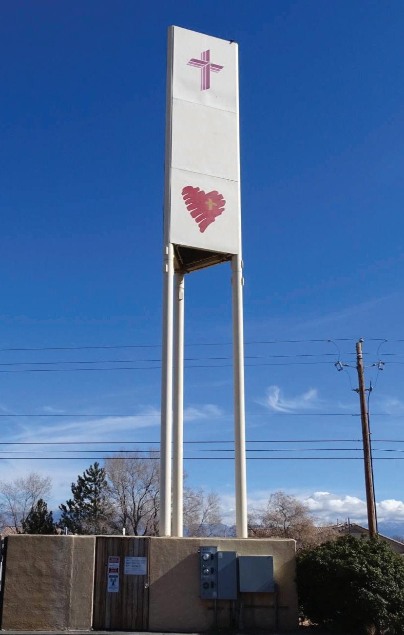
Many telecommunications towers conceal their true purpose. That towering pine tree alongside the highway? It might be broadcasting your phone signal. The church steeple in your neighborhood? It’s possibly serving as a telecommunication site. The flagpole at city hall? It might also be a monopole. As networks demand ever-denser infrastructure, engineers are designing towers that hide in plain sight, and the structural challenges are far from ordinary.
Telecommunication towers form the backbone of cellphone networks, accommodating various generations of expansion including 5G. However, emerging technologies sometimes face mounting resistance from communities that reject visually prominent macro towers, especially within urban districts, scenic corridors, and protected landscapes. As the United States’ telecommunications tower network surpasses 154,800 structures, with concealment designs gaining momentum at a projected growth rate of nearly 6.9% annually,
Fig. 1. Added mass in the form of vegetation like with this monopine structure raises the tower’s center of gravity and increases moment arms for lateral loads, requiring careful evaluation of foundation adequacy and base connection capacity to resist amplified overturning moments under combined loading scenarios.
a thorough understanding of the structural impact of camouflage assemblies is more important than ever.
This article discusses structural engineering considerations for concealment telecommunications towers, from loading complications to radio-frequency (RF) transparent materials, operational challenges, and cost-benefit analysis.
The Driving Forces Behind Concealment Towers
Concealment towers emerged in the early 1990s to mitigate public opposition to industrial infrastructure. Conventional lattice and monopole structures faced widespread community pushback. Property owners, civic authorities, and conservation organizations increasingly
perceive traditional towers as visual degradation that reduces property valuations and contradicts neighborhood identity. Consequently, the telecommunications sector developed concealment methodologies that include vegetation simulations, architectural integrations, and disguise designs to fit the surroundings while fulfilling connectivity requirements and reducing visual prominence. Larson Camouflage pioneered the first “monopine” in Monument, Colorado (near Denver) in 1992. The Telecommunications Act of 1996 accelerated their use by restricting local governments from banning towers while permitting aesthetic mandates. While concealment typically requires a significant capital cost premium over conventional towers, carriers increasingly accept these economics in exchange for expedited permitting and reduced community opposition.
Common concealment types for macrotowers include, but are not limited to:
• Monopoles resembling trees or vegetation.
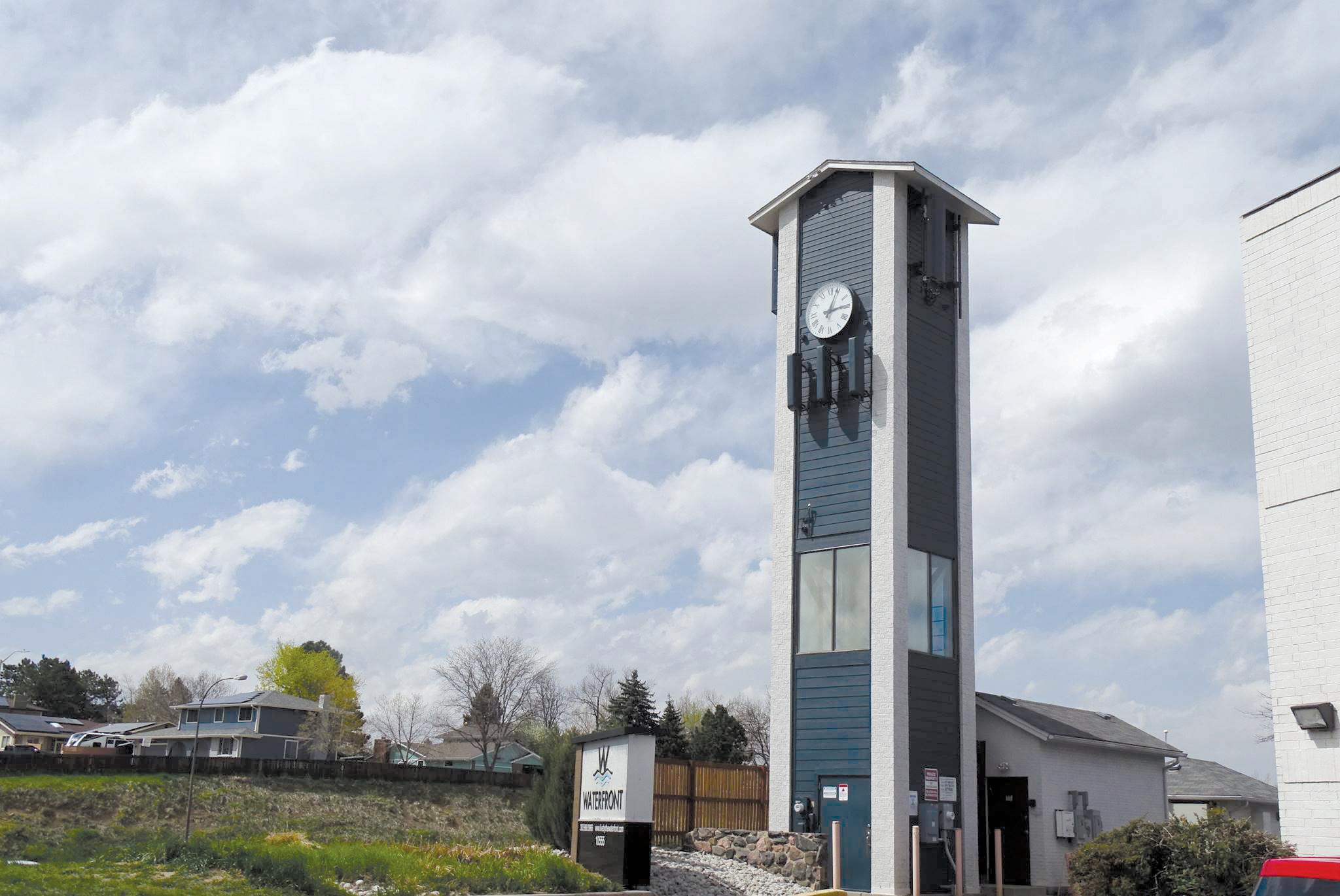
• Architectural enclosures mimicking clock towers, steeples, or silos.
• Rooftop and building-integrated screening systems.
• Decorative shrouds and radomes.
Each approach introduces structural considerations that differ significantly from conventional exposed towers.
Materials
Hot-dip galvanized structural steel forms the primary load-bearing monopole or lattice framework for telecommunications towers. Engineers apply concealment materials to these steel cores, which must satisfy requirements for RF transparency, structural durability, aesthetic fidelity, and long-term weathering resistance.
Fiber-reinforced polymer (FRP) composites serve as the principal material system for RF-transparent cladding applications. Glass fiber-reinforced polyester or vinyl ester resins combine adequate mechanical strength with RF transparency, maintaining signal transmission losses below 0.5 dB across cellular frequency bands. These materials draw heritage from aerospace radome construction, where similar composites have demonstrated reliable performance protecting radar and communications equipment. Fabricators can mold FRP sections to precise geometries replicating architectural elements or natural forms, with surface treatments providing texture and coloration matching regional aesthetics. Modern fabrication techniques enable integration of metasurface patterns and specialized coatings that enhance both optical and RF transparency while maintaining structural integrity.
Monopine and monopalm vegetation-simulated towers employ distinct material assemblies. Manufacturers fabricate synthetic branches from ultraviolet (UV)-stabilized high-density polyethylene (HDPE) or polypropylene that incorporate hindered amine light stabilizers (HALS) and UV absorbers to resist UV breakdown from sun exposure. Industry-standard accelerated weathering protocols per ASTM G154 verify performance exceeding 3,000 hours equivalent exposure. Internal galvanized steel wire armatures provide mechanical support while maintaining RF transparency through minimal electromagnetic interaction. Bark cladding employs glass FRP sections that manufacturers mold from actual tree specimens, with polyurethane foam cores reducing weight and UV-stabilized gelcoat finishes providing color stability. Material specifications balance operational requirements including RF transparency, impact resistance per IEC 62262, temperature stability from –40F to +175F, and aesthetic durability, though UV-induced polymer degradation necessitates component replacement.
Fig. 2. This flagpole is also a telecommunications tower.
Fig. 3. Concealment assemblies like this church steeple tower add extra weight and wind area that can substantially increase total loading.
Fig. 4. A tower disguised as a cactus provides cellphone service to the community without degrading the area’s scenery.
Structural Challenges of Concealment
The specialized materials the previous section describes enable concealment towers to blend into diverse environments while maintaining RF transparency. However, these aesthetic solutions introduce unique structural engineering challenges that conventional monopole towers do not face. The addition of synthetic foliage, cladding panels, and textured surfaces significantly impacts load calculations across all design criteria including dead load, wind pressure, ice accumulation, and seismic response, requiring careful analysis to ensure structural adequacy. Furthermore, ANSI/TIA222 (Structural Standard for Antenna Supporting Structures, Antennas and Small Wind Turbine Support Structures) load combinations that govern tower analysis and design become more critical for concealment structures due to their increased surface area and mass, which amplify both wind-induced overturning moments and seismic base shear demands.
Dead Load Complications
Traditional monopole and lattice configurations carry relatively predictable loads: structural steel, antennas, transmission lines, and mounting hardware. Concealment assemblies add extra weight that can substantially increase total loading. Vegetation simulation arrangements employ frameworks of steel or fiberglass appendages radiating from central poles, with each appendage supporting clusters of synthetic foliage that manufacturers produce from UV-resistant polymer compounds. Full-height vegetation concealment on typical monopoles may contribute approximately 75% or more in additional distributed loading along tower elevation depending on the tower height and required density of foliage, with mass concentration at appendage attachment locations. Architectural concealment structures introduce different loading patterns; cylindrical FRP canisters and flagpole enclosures typically add more than 10% in additional dead load as relatively uniform distributed loading along the concealed portion of the shaft; and clock
tower and steeple assemblies with heavy facade components can result in 30% to 100% higher dead loads compared to similar self-support towers. These added masses raise the tower’s center of gravity and increase moment arms for lateral loads, requiring careful evaluation of foundation adequacy and base connection capacity to resist amplified overturning moments under combined loading scenarios.
Wind Loading Ramifications
Wind loading governs most telecommunications tower designs. Concealment components substantially increase both drag coefficients and effective projected surfaces relative to exposed steel configurations. Comprehensive wind tunnel testing and computational fluid dynamics (CFD) evaluations document that vegetation simulations and architectural enclosures can increase base overturning moments by 60% to more than 200% compared to conventional exposed towers. Tree-camouflaged monopoles experiencing 100% moment increases require fundamental structural redesign through thicker pole sections, larger foundations, or both.
Slender, smooth-surfaced concealment structures, particularly flagpoles and canister/radome-enclosed monopoles with cylindrical profiles, remain vulnerable to vortexinduced vibration within specific wind velocity ranges. As wind flows past these structures, alternating vortices shed from either side, creating a Kármán vortex street in the wake. When the vortex shedding frequency approaches the structure’s natural frequency, resonance can occur, producing
crosswind oscillations perpendicular to wind direction. Research on flagpoles and tubular telecommunications towers indicates vortex-induced vibration typically occurs at moderate wind speeds (12-30 mph), generating millions of fatigue cycles annually that threaten critical connection integrity. ANSI/TIA-222 Revision I expanded fatigue loading assessment provisions to include monopole structure, recognizing that repeated wind cycles can cause failure at base plates, anchor bolts, and welds, even when the design satisfies ultimate strength criteria. Engineers must evaluate these connections using appropriate stress range criteria, with particular attention to monopole structures where oscillations and vortex shedding can accumulate damaging stress reversals over the tower’s service life. Mitigation strategies include helical strakes, spoilers to disrupt vortex formation, vented canisters to break vortex coherence, or tuned mass dampers to dissipate vibrational energy.
Ice Loading Considerations
In regions susceptible to freezing precipitation, ice accumulation creates particularly severe loading conditions. Ice bridging between closely positioned components can transform nominally open frameworks into near-solid surfaces with dramatically increased wind exposure. Engineering methodology must incorporate conservative assumptions about ice formation patterns (typically 0.5-to-1.0-inch radial ice with concurrent wind) or pursue wind tunnel examination with iced models to develop defensible load scenarios for structures in ice-susceptible regions.
Fig. 5. Clock tower and steeple assemblies with heavy facade components can result in 30% to 100% higher dead loads and 2 to 6 times higher wind area compared to similar self-support towers.
The supplementary loading, altered aerodynamics, and access complications that concealment assemblies introduce are readily manageable through established engineering methods.
Seismic Considerations
Seismic evaluation of concealment telecommunication structures requires special attention because architectural cladding, added mass, and non standard geometries influence dynamic behavior in ways not observed in conventional monopoles or lattice towers. Concealment designs such as monopines, stealth flagpoles, slimline canisters, and cupola type enclosures rely on FRP cladding and irregular internal framing that increase effective seismic weight and modify stiffness distribution along the height. Flagpole and slimline canister sites exhibit pronounced mass and stiffness irregularities along their height, creating complex modal responses that deviate from conventional tower behavior. These variations amplify higher mode participation and introduce torsional effects, making multi modal response spectrum analysis essential in seismic regions governed by ANSI/TIA 222 and ASCE 7. Tree type monopoles also develop eccentric mass from branch framing, which increases torsional irregularities and drift sensitivity. Material compatibility also plays a critical role: lightweight FRP cladding can crack or detach under seismic deformation if engineers do not detail connections to accommodate differential movement relative to the steel support frame. Engineers must model the influence of nonstructural components, capture P Δ effects, and verify serviceability drifts to ensure both structural integrity and concealment performance during seismic events.
Tools and Software
Analysis and design of concealment telecommunication towers follow conventional monopole or lattice procedures, with additional considerations for increased wind drag, shielding effects, and discrete attachment loads from shrouds, radomes, and synthetic tree appendages. These analyses rely on industry-specific software capable of automating ANSI/TIA-222 load generation, P-Δ nonlinear analysis, and member design checks. Widely adopted platforms include tnxTower, OpenTower, and ASMTower, each offering specialized capabilities for tower modeling, appurtenance libraries, and code-compliant design. Many tower engineering firms also employ alternative commercial platforms or proprietary in-house software tailored to their specific design workflows and quality control processes. General-purpose finite element programs such as STAAD Pro and RISA-3D supplement
these tools for complex connection and foundation analysis. L-Pile is the industry standard for modeling nonlinear soil-structure interaction, specifically utilized to analyze the lateral load-bearing capacity and deflection of deep foundations under high overturning moments. Microsoft Excel and Mathcad remain prominent supplements for custom engineering calculations, particularly for base plate design, anchor bolt checks, and site-specific load derivations. Concealment elements present unique analytical challenges because standard drag coefficients and effective projected areas do not account for irregular shapes such as synthetic branches and textured cladding. Engineers frequently derive custom effective projected area values through CFD modeling or wind tunnel testing to accurately quantify wind loading on non-standard appendages, especially for monopine and monopalm configurations where branch density significantly influences aerodynamic behavior.
Operational Sustainability and Future-Readiness
Concealment assemblies must accommodate routine inspection and equipment modifications without extensive disassembly. Effective access strategies include removable panels aligned with antenna locations and adequate clearance around equipment to permit safe working positions. Monopine and monopalm systems employ modular branch attachment architectures utilizing standardized receptors welded to monopole structures, enabling cross-manufacturer compatibility for replacement components. Manufacturers aim to produce replacement branches adaptable to most receptors, facilitating component replacement without complete tower disassembly.
Concealment configurations must provide antenna mounting zones with sufficient volume and structural capacity to accommodate equipment upgrades. Providing concealment volumes with generous margin beyond initial requirements helps avoid premature obsolescence and enables technology upgrades without structural modifications.
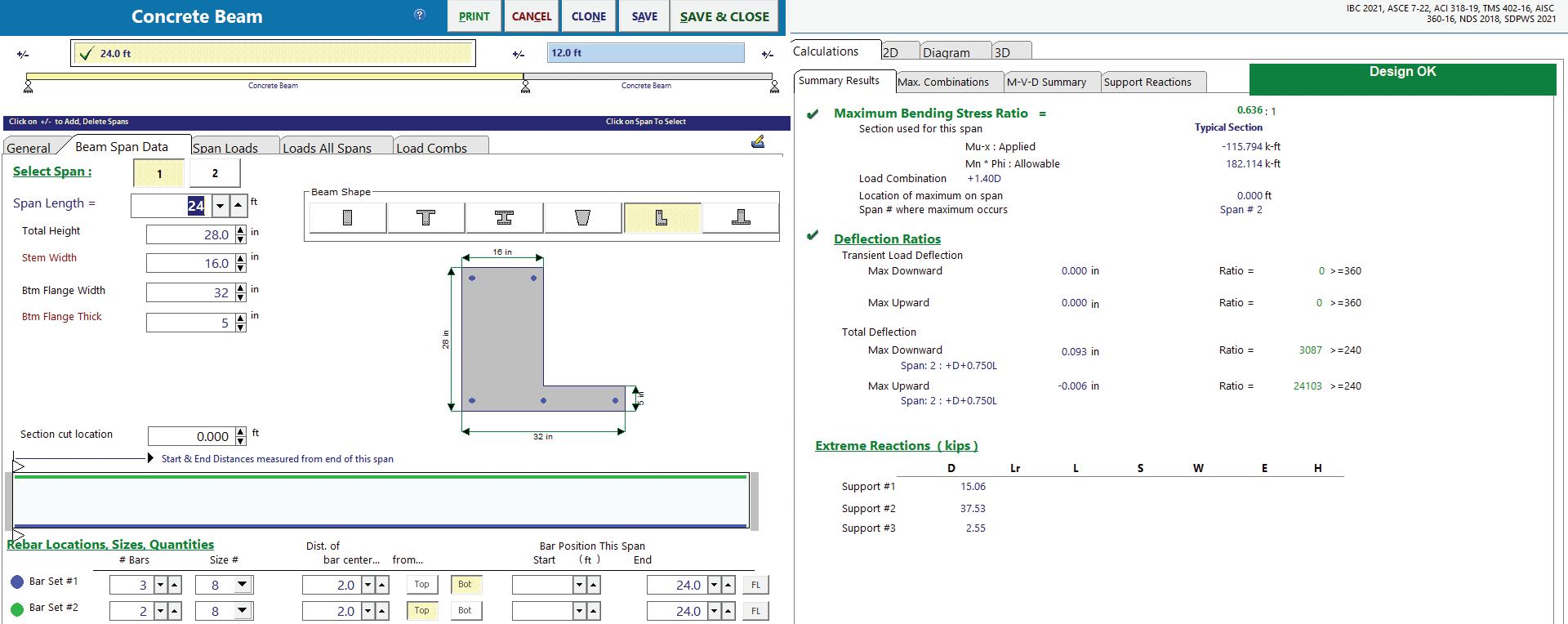
AUTOMATED RC COLUMN DESIGN & SCHEDULE
ANSI/TIA-222 recommends minimum structural inspection intervals of five years for self-supporting monopole towers, and the standard recommends more frequent assessments for coastal or corrosive environments. Comprehensive inspections involve climbed assessments by certified technicians examining structural members, connections, and mounting hardware. Many operators supplement these with annual ground-based visual inspections examining base conditions and concealment integrity without climbing personnel. ANSI/TIA-222 Revision I recognizes drone-based inspection technologies enabling detailed documentation while reducing climbing requirements. Inspection protocols for concealment tree assemblies emphasize branch receptor security, foliage UV degradation, and bark cladding condition. Maintenance budgets must acknowledge concealment components as consumable items requiring periodic replacement at intervals shorter than primary structure service life.
Cost-Benefit Analysis
Telecommunications tower deployment costs vary considerably by structural typology, and concealment requirements continue to introduce meaningful cost premiums relative to standard monopoles. Recent industry data place typical U.S. monopole construction costs at approximately $250,000 for towers in the 100- to 200-foot range, inclusive of foundations, structural steel, site preparation, and installation activities. Although these installations satisfy functional and structural performance demands, they offer limited aesthetic accommodation.
Increasingly stringent zoning ordinances and municipal review processes have elevated aesthetic considerations, leading carriers toward concealment-based solutions. Industry analyses indicate that camouflage tree towers can cost 1.5 to 3 times as much as standard monopoles, largely due to FRP cladding, synthetic foliage, custom fabrication, and extended installation needs. For monopine or monopalm designs, this often translates into six-figure cost increases above baseline tower budgets. Although specific nationwide figures vary, the added cost of specialized components such as UV-stabilized branches, bark-texture finishes, and custom mounting systems accounts for most of the premium.
From a project-delivery standpoint, concealment often functions less as an elective architectural upgrade and more as an enabling condition for site approval. In jurisdictions with stringent aesthetic expectations or active community opposition, carriers routinely accept higher upfront capital costs to avoid protracted entitlement cycles, redesign requirements, or application denials. As a result, concealment structures frequently represent the only technically and commercially viable solution for deploying infrastructure in regulated or community-sensitive settings.
Conclusion
The structural engineering of concealed telecommunications towers represents a multifaceted challenge demanding integration of aesthetic configuration, structural evaluation, materials science, and regulatory compliance. As network proliferation continues to drive facility expansion, concealment approaches that balance community expectations with engineering rigor will only grow in importance.
Effective concealment need not compromise structural integrity or operational functionality when design teams apply systematic evaluation, leverage appropriate materials, and remain attentive to operational requirements. The supplementary loading, altered aerodynamics, and access complications that concealment assemblies introduce are readily manageable through established engineering methods such as finite element analysis, supplemented by tools including computational fluid dynamics and wind tunnel testing, and advanced composite materials.
Success in this specialized field depends on close collaboration among structural engineers, RF engineers, architects, material suppliers, and regulatory consultants with disciplined communication and welldefined responsibilities across project stages. And perhaps next time you encounter what appears to be a conventional architectural feature, a moment’s observation may reveal an engineered concealment structure quietly fulfilling its role in the continuum of modern connectivity. ■
Full references are included in the online version of the article at STRUCTUREmag.org .
Sudarshan C Kasera, PE, PMP, is a Senior Project Engineer at Crown Castle, a leading provider of shared wireless infrastructure in the U.S. With over ten years of experience, and significant responsibility as a licensed Professional Engineer, Kasera has made impactful contributions to the safety, resilience, and sustainability of telecommunications infrastructure nationwide. (Sudarshan. Kasera@Outlook.com)
The opinions expressed herein are the author’s own and do not necessarily represent those of his present or past employers.
BEYOND GWP
Sustainable project design goes beyond lower Global Warming Potential (GWP) targets and requires:
Komponent shrinkage-compensating concrete optimizes sustainability while improving structural behavior, dimensional stability, and durability.
Improved construction efficiencies help meet demanding project schedules and speed time to completion.
Request optimized design support, specification assistance, EPD information, or other project support needs.
Susan Foster, sfoster@ctscement.com, (714) 614-7392
Scan to read about our
capabilities
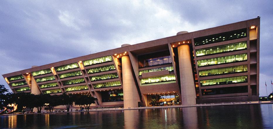
Dallas City Hall: 50 years and going strong. Sustainability that outlasts the GWP metric.
structural DESIGN
Considering Engineering Judgment in Forensic Investigations
The structural engineer is often relied upon to make crucial, time-sensitive decisions in the event of structural failure, sometimes with limited information and without extensive analysis. Three case studies look at real-life emergency scenarios requiring rapid decisions in structurally compromised situations.
By Ross Smith, PE, LEED AB BD+C, CDT
As engineers advance through school and embrace their larval state as practitioners, they eventually encounter the concept of “Engineering Judgment.” For many, initial perceptions of the phrase are dubious or even dismissive, inferring shortcuts bypassing important steps. These notions usually evolve as most realize it is more than a “gut-feeling;” the foundations of technical knowledge, expertise, and professional standards can only be forged in a slow kiln of gained experience. This truth rings especially true for forensic consulting engineers whose engineering judgment takes on additional dimensions including navigating emotionally-charged situations, time-sensitive contemplations, and recent or impending catastrophes. In most cases, engineering judgment is required long before any actual analysis is undertaken.
Using an adaptation of a recent interactive NCSEA Structural Summit Presentation and national NCSEA Webinar, several real-world case studies exhibiting engineering judgment are presented herein. Before learning how the author applied judgment, the reader is invited to reflect on proposed considerations and determine what actions they would choose had they stepped into the fray, and then compare with what was actually decided. The cases are not meant to proclaim decisions as right or wrong, but rather to encourage immersion in the thought experiment process and applying one’s own engineering judgment to uniquely challenging scenarios.
Case Study 1: Fire at the Corner of History
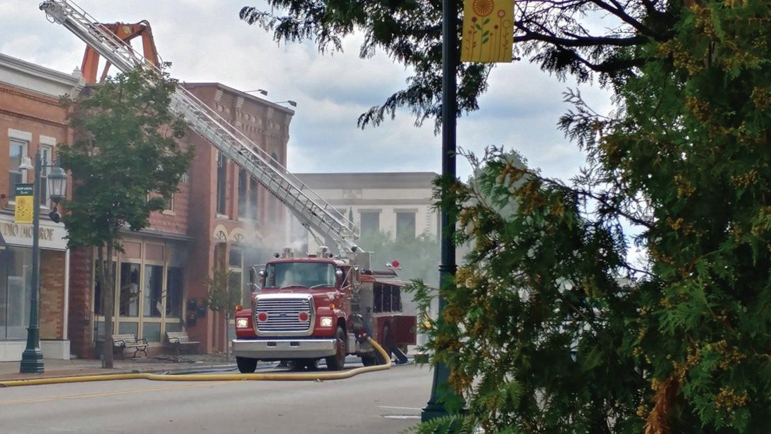
Constructed in 1873, a small riverside town’s oldest brick building, and a favorite restaurant to generations of locals, became the focus of an early summer morning emergency: a dumpster fire had spread and engulfed large portions of the treasured structure. The engineer receives a call with urgency typical of a no-notice incident response, but with a new wrinkle: the building is still on fire.
Engineering consulting is often a difficult job, with difficult tasks and demands for quick decisions. This time, before even accepting the assignment, engineering judgment is required as the engineer considers how to evaluate the state of the emergency:
1. The fire makes unsafe conditions; delay visit until further notification.
2. An engineer may be of help and can wisely navigate conditions. Go to site promptly.
Interested in the uniqueness of the challenge, after some internal deliberation, the engineer chooses to visit the site immediately, consulting a senior colleague en route to discuss strategies and get another valued opinion. Upon arrival, the engineer is greeted by the local fire chief who promptly demands, “I need you to tell us to take down the
building.” Moments later, distraught building owners begin pleading for the engineer to save the historic landmark (Fig.1).
Amidst a tense scenario with conflicting parties and no time to burn, the engineer considers how to characterize their own responsibility:
1. An engineer has an ethical obligation to protect public.
2. An engineer is not a firefighter; they can’t make decisions on an active fire site.
3. An engineer knows the most about buildings and structures.
4. An engineer is not the building owner and can’t decide for them. Since safety of the fire fighting crew was paramount, the engineer defers fire-related decisions to the fire chief, but suggests that if an inspection can be undertaken reasonably safely, it may be possible to save the remaining portions of the structure. Through continued extinguishing efforts, the flames are controlled, but the engineer struggles with how to gain reasonably safe access beyond grade level observations from afar. On a hunch (and perhaps manifesting a childhood dream) the engineer asks the chief if the high-reach aerial ladder truck currently in use by a hose-wielding firefighter can be utilized for a better view. Surprisingly, the chief agrees, and after donning the appropriate PPE, the engineer climbs to the top of the fully extended ladder.
Watch the Webinar
Watch the on-demand webinar on this same topic, “What Should We Do Now? Implementing Structural Engineering Judgment in Urgent Response to Localized Structural Failure,” by author Ross Smith at www.ncsea.com/webinars.
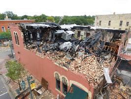
Fig. 1. When a historic landmark in a riverside town caught fire, local authorities suggested demolishing the entire structure, while the owners were hopeful the restaurant could be saved.
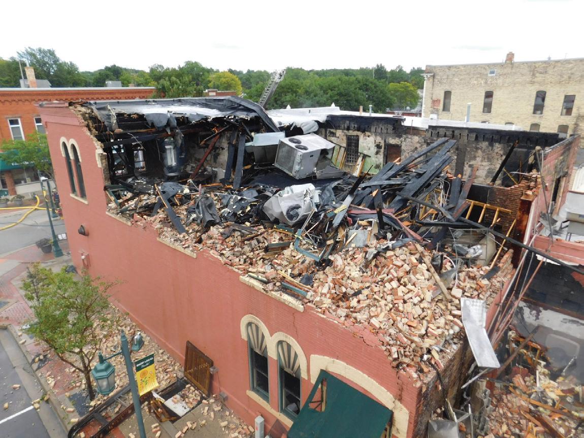
The new perspective makes all the difference (Fig. 2). It becomes clear that while the north and west walls of the second floor are severely damaged, the east and south walls are intact, including most of the historic east facade. Equally important, the second-floor framing is largely intact but is now supporting a tremendous amount of debris.
After descending, the engineer relays thoughts to both the fire chief and the owners. Assuming the fire can be extinguished, the remaining portions of the building can be saved but in doing so there are two short-term key considerations: structural stability and public safety. Regarding stability, since the intact second-floor framing is overloaded, the debris should be removed as quickly and delicately as possible. Further, given the compromised roof and second-floor diaphragms, the remaining partial walls require shoring from both the inside and outside.
Due to the unbraced west and south exterior walls, street and sidewalk closures are required to address public safety. But as with any scenario where the engineer recommends temporary closures, the question of extent lingers. The fire chief wants to minimize disruption to the roads and local businesses, meanwhile the engineer worries that if the unstable, two-story walls fall outward, the debris can catapult into the storefronts across the street, endangering people and property. As the engineer considers barricades, a stroke of ingenuity is offered by another engineer on site representing the town: a series of tall roll-off steel dumpsters could be ordered and lined up in the far parking lanes of the opposing streets. The two-layered steel wall will form a barrier protecting the storefronts and are cheaper and faster to mobilize than designing and constructing a traditional wall. In this case, utilizing engineering judgment meant receiving good ideas from other sources which helped wisely set appropriate, effective boundaries.
Aligning the many swift decisions and recommendations, the judgmentbased plan worked. Barricades and shoring provided protection and stability, the remaining iconic facade was saved, the damaged areas rebuilt, and the community was thrilled to have its favorite haunt reopened for business.
Case Study 2: Collapse Class is in Session
A high school building, originally built in 1924, with at least four large additions over the decades, stands proud: a two-story fortress of brick masonry, protecting a century of history and serving as the centerpiece of a thriving urban community. One sleepy June morning, merely a week after the start of summer vacation, a maintenance team
discovers a partial roof collapse, stirring the staff, administration, and the surrounding neighborhood. Soon after, the engineer is contacted and conscripted into the investigation.
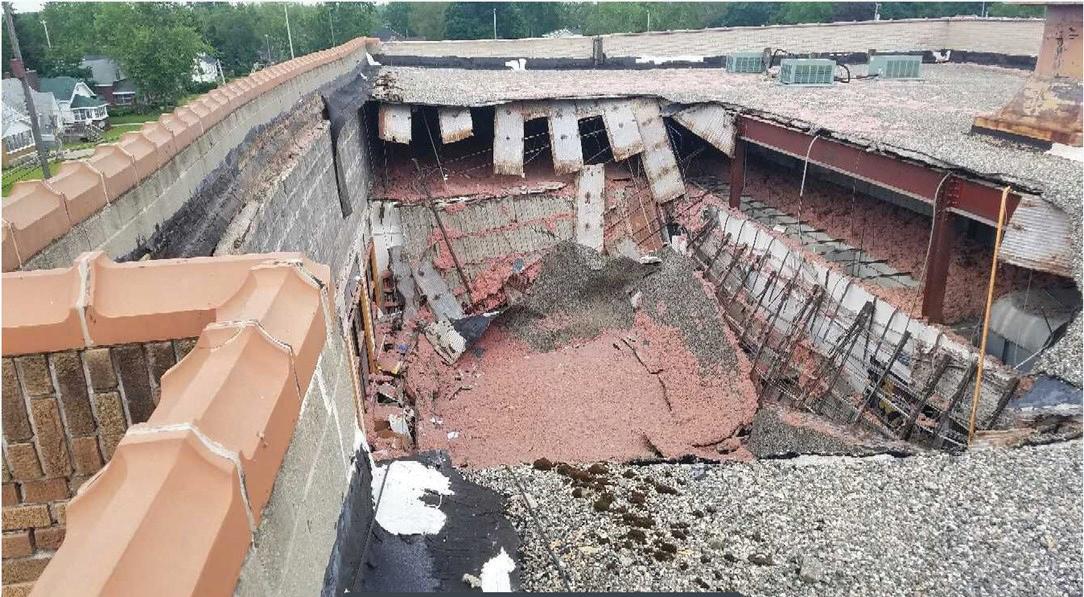
Upon arrival, response activity is underway including limited shoring of one exterior wall and a tarp draped over the newly sunken roof area. Inside, initial inspection on the first floor offers only seemingly innocuous displaced ceiling tiles but prying open the door of a second-floor classroom reveals a tangled mess of collapsed open-web steel bar joists and an accumulated heap of roofing, ceiling tiles, and classroom furniture. Anecdotal input from some brazen roofers who had been walking on the debris pile informed the engineer they had heard some building groaning noises, but that the pile had only moved “a little” during their emergency tarping work (Fig. 3). Eager to investigate, but short on information and registering a likely framing overload, the engineer contemplates various notions of what areas should be accessed and how:
1. Enter debris field carefully. Multiple roofers worked several hours already and were fine, effectively providing a larger load and longer duration than one engineer entering for a few minutes.
2. Do not enter collapse area. The second floor is now carrying significantly more load and has already suffered a dynamic loading beyond its design intent.
3. Do not enter any portion of the building. Construction details of the failed area are unknown, as is the failure mechanism. The entire structure could be compromised.
The engineer elects to continue investigating from stable surrounding positions but chooses not to enter on top of or beneath the collapse debris. That risk is unreasonable, despite the roofers’ assurances. After a few hours of observation and discovering original building drawings, the engineer confers with the on-site response team to discuss shortterm key considerations: water management and restricting access. While ponding water often raises concern of additional load accumulation, inspections also reveal the electrical switchgear for the entire campus is housed in a basement vault adjacent to the collapse and had reportedly filled and been pumped out once already. With redirectional tarps and basic drainage provisions already deployed, safe maintenance of the makeshift system was critical to prevent water from ponding on top of the collapse, which may exacerbate it, or from collecting in the basement which could debilitate the entire complex.
Staff curiosity dictates strict closures around the collapsed area, both inside and outside the school. Fortunately, existing fire separations and structural isolation provide an opportunity for installation of hard barriers and keyed entrances to deter and protect would-be explorers.
After the initial considerations, uneasy whispers and assumptions run rampant, with various opinions swirling about how much of the building
Fig. 2. A view of the restaurant from above revealed the east and south walls were intact, including most of the east facade.
Fig. 3. A partial roof collapse was discovered at an isolated section of a school building—one week after classes finished for the summer.
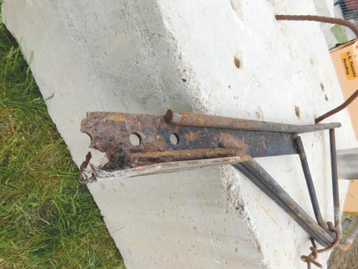
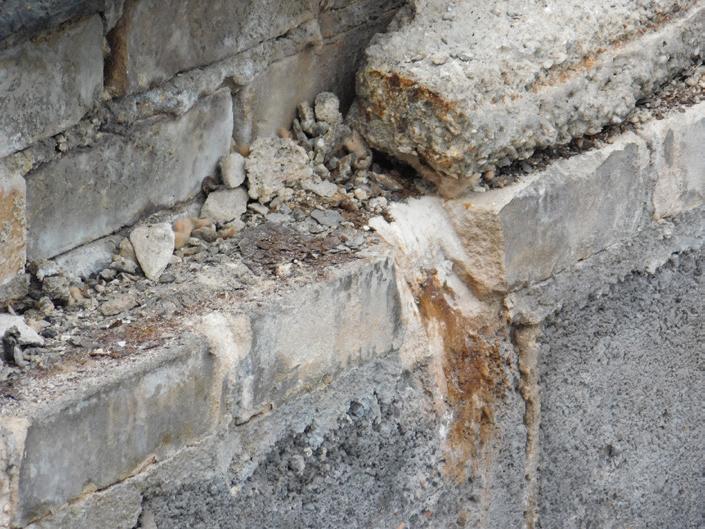
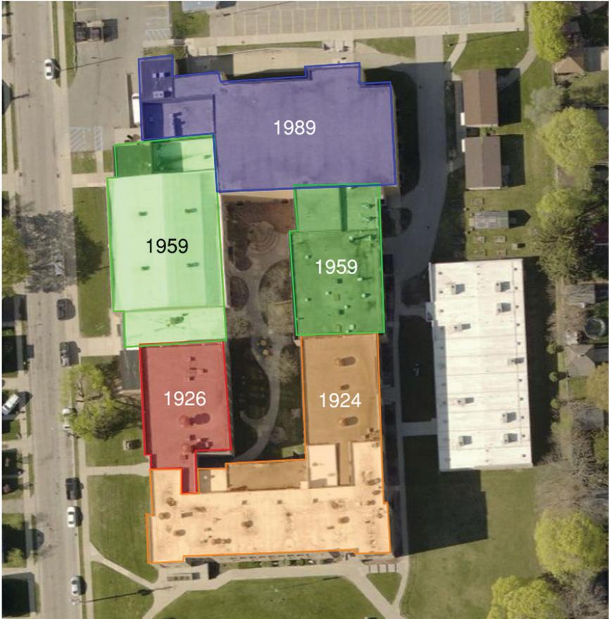
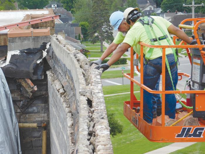
needs to be demolished, how quickly the school can be re-opened, and how did this all happen. It takes the engineer numerous meetings with the school board to eschew others’ aggressive demolition plans and recommends to the decision-makers that the engineer be allowed to conduct a surgical disassembly of the remaining wall and debris pile. With the help of a skilled deconstruction team, salvaged artifacts reveal the roof joist bearing seats were corroded through and the supporting masonry wall eroded. An iterative cycle of section loss and a sliding bearing loss ended in a sequence of joist failures and catastrophic collapse (Fig. 4.). Though the failure surprisingly occurred at the high side of the roof slope, brick patterns and mortar coloration suggested years of parapet infiltration and deterioration led to a prior coping and wall replacement decades ago, but hidden structural damage just below the roof was never understood, accessed, or addressed. With the cause understood and with the failure located specifically in the 1926 addition, the engineer wonders: Where else might this condition be looming? Which of the building sections need to be reviewed (Fig. 5)?
1. Remaining 1926 construction.
2. 1924 construction.
3. 1959 construction.
4. 1989 construction.
At a minimum, the engineer recommends review of the other 1926 areas, any similarly constructed conditions, and conditions of similar age. Select inspection openings expose pristine conditions at the remaining steel joists bearings while a series of thorough attic inspections reveal the 1924 and 1959 vintage building portions host a completely different, wood-framed system and confirm that they are in good condition.
To support these positive results, the school board requests the engineer present findings in a forum with administration, staff, and parents to alleviate remaining community concerns regarding the aged building. Balancing helpful intentions against liability concerns, the engineer mulls whether to present findings in a public forum.
1. Yes! The engineer may finally gain well deserved respect and recognition.
2. Absolutely not. It’s a risk of misinterpretation in an uncontrolled environment.
3. If necessary, it’s sometimes part of the responsibilities of professional service.
Ultimately, the engineer presents to a standing-room-only gathering. The results are conveyed and questions answered in a largely successful forum, notwithstanding a scuffle between staff and an overeager local news reporter, and an unfounded accusation that the engineer should be imprisoned for culpability with regard to the performance of a building designed and built over 50-years before their birth.
With demolition of the unstable areas complete and plans for replacement emerging, the engineer’s focus shifts to conducting a life safety analysis and working with local fire authorities to ensure re-occupancy of the building. As August arrives the final letter and drawings are approved and school opens on time. Years later, a brand-new building segment is opened, replacing the collapsed portion with new classrooms and new interactive spaces to enrich student experiences.
Case Study 3: An Unexpectedly Uplifting Situation
After an elementary school is glanced by an EF-1 tornado, the district superintendent and a trusted construction management partner contact the engineer to request assistance.
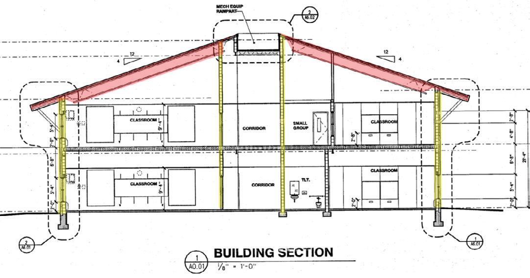
Completed in 1997, with a 2001 southern addition, the long, sweeping crescent shaped building’s two stacked stories each feature a double-loaded central hallway serving classrooms on either side. The building framing includes sloped open-web steel joists bearing on interior and exterior concrete masonry walls with an indented mechanical equipment rampart in the middle (Fig. 6).
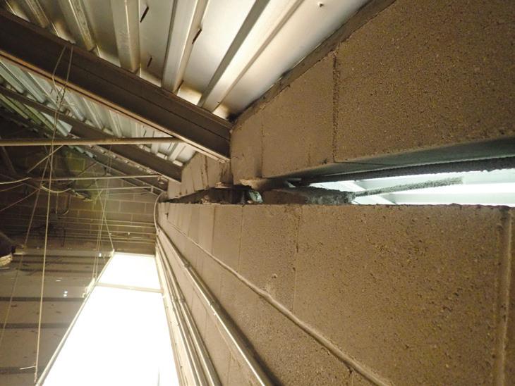
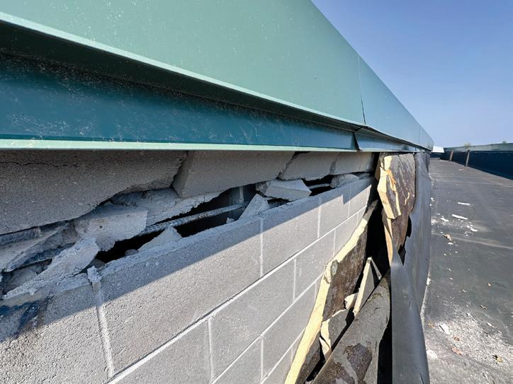
Upon arrival to site, the engineer assesses each room on each level for distress. At the southern end of the second floor, the engineer finds isolated concentrations of vertically displaced joists and separated/shattered bond beams and disengaged grout, including areas where chunks of concrete
Fig. 4. During deconstruction, it was revealed joist bearing seat section loss, erosion, and sliding at the masonry bearing ledge led to eventual collapse.
Fig. 5. After understanding the cause of the collapse, the structural engineer must determine what other building sections need to be reviewed for similar underlying conditions.
masonry had fallen through the ceiling (Figs. 7 and 8). Throughout the rest of the building, concrete masonry cracks are observed near the upper corners of most windows. In characterizing concerning, event-related damage the engineer considers various possibilities:
1. Any CMU or other cracking should be considered tornado-related.
2. The event only affected the top floor; Only top floor cracking is considered tornado-related.
3. Displaced joists and masonry are tornado-related; The other cracks are incidental and not concerning.
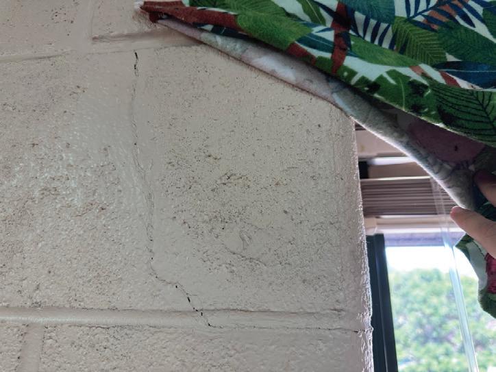
The corner cracks exhibit no evidence of recent origin, and many have dust within or paint across their gaps (Fig. 9). Accordingly, the engineer’s concerns are reduced to the more severely distressed area at the southern end of the second level. Hearing this provisional conclusion after already canceling a few days of school, a school official poses a question for the engineer’s next deliberation: How much of the school needs to be closed:
1. No closures are required. The joists and walls are damaged but now stable.
2. Can’t be too cautious—there are kids in there! Close the entire school until repairs can be implemented.
3. Close all second-floor rooms.
4. Close only the rooms exhibiting damage.
The engineer outlines two key considerations: in terms of damage, only a handful of second floor rooms require closure. However, since some instabilities remained, until joists and CMU walls are repaired, vertical shoring will be required. Analysis of the second-floor precast hollow core concrete structural system determines it cannot support shoring loads—the shoring towers will need to extend into the undamaged, first floor classrooms as well. The engineer expected shoring would be too
disruptive, thus forcing the closure of six additional classrooms, rendering the school out of space and forcing temporary relocation of the entire institution. In an inspiring act of resilience, inconvenience gave way to resourcefulness, as the principal and affected teachers instead choose to decorate the shore towers and simply work around them. With this flexibility and repurposing of other spaces within the facility, classes resume the following week.
With prompt repairs the stated priority, working with the city and state authorities having jurisdiction, and coordinating with the construction manager, the engineer advises postponing a causation report and moving forward with two repair packages: one for concrete masonry repairs (short lead time, weather-sensitive) and a second phase for damaged steel bar joists (longer lead time, no weather implications). The repair team works stealthily and strategically to limit noise disruptions and successfully complete the masonry work before winter holiday break. They finish the joist repairs a few months after - under budget and ahead of schedule. Once the shoring towers are removed, the ceilings are restored, and the walls receive a fresh coat of paint, the entire school community is elated to finish school year the way they had originally intended.
Conclusion
Engineering judgment is not merely an antiquated euphemism. It is real, reliable, and becomes increasingly critical as situations become more complex. Though intangible and impossible to physically hold, engineering judgment must be grasped and executed by practitioners in all facets of project decisions, especially in unstable scenarios. It is the net sum of each individual’s education, expertise, and experience but regardless of how many decades of experience one has, the best way to hone engineering judgment is to confer with technical colleagues along the way. Healthy skepticism and rigorous discussion ultimately lead to better results allowing us to achieve project objectives agreeable to all parties and protect the public along the way. ■
Ross J. Smith, PE, LEED AB BD+C, CDT, is a Principal at WJE with over 25 years’ experience in investigations of structural and architectural failures related to water infiltration, fire, wind, snow, condensation, and unique material failures. He also works in structural evaluation, repair design, construction quality control, and building enclosure commissioning (BECx). He is experienced in new building design, sustainable construction, peer reviews, and litigation assistance.
Fig. 6. The building frame of the school hit by a EF-1 tornado had sloped open-web steel joists (red shading) bearing on interior and exterior concrete masonry walls (yellow shading). An indented mechanical rampart was located in the middle.
Figs. 7-8. Isolated concentrations of vertically displaced joists and separated bond beams were found at the southern end of the school’s second floor. Though difficult to see, the grout did not effectively bond with the reinforcement. Further, the vertical reinforcement did not properly extend into the bond beam at the top of the wall.
Fig. 9. Corner cracks, with paint across them or dust within them, did not appear to be recent.
in FOCUS
Answering the Call: Structural Engineers, and Disaster Response
This article is the first of a three-part Joint Summer Series, “Disaster Response and Lessons Learned,” produced by NCSEA, SEI, and CASE.
By Klaus Perkins, PE, SE
Iremember the first time I stood in front of a damaged building after an earthquake. The family was living in a tent in their front yard for fear of going back into their home and I was going through my training to make sure I provided the right assessment before moving to the next building. It was at that moment that my role as a structural engineer during a disaster became very real: providing a clear, defensible answer using judgment, experience, and limited information.
When a disaster strikes, whether from earthquakes, hurricanes, floods, tornadoes, or wildfire, communities immediately turn to engineers for answers. Among the most urgent question is a simple but critical one: Is it safe? For practicing structural engineers, answering that question defines our role in the immediate aftermath. Unlike traditional design work, disaster response is fast-paced, field-driven, and focused solely on life safety.
From my own perspective as a practicing structural engineer, the first time you walk into a post-disaster environment is unlike anything encountered in day-to-day practice. There are no complete drawing sets, no time for analysis models, and no opportunity to step away and “think it through” later. Decisions are made in minutes, often with incomplete information, and those decisions directly impact whether people can return home/reopen business or need to stay out of harm’s way. That reality fundamentally changes how we approach engineering.
Structural engineers play a vital role in answering that question during the chaotic days following a disaster. Through coordinated post-disaster safety assessments, engineers help protect lives, support emergency operations, and enable communities to begin recovery. At the national level, the National Council of Structural Engineers Associations (NCSEA), through its Structural Engineering Emergency Response (SEER) Committee, provides leadership and a consistent framework to ensure that engineers are prepared to respond effectively and responsibly.
As disasters increase in frequency and severity, the profession’s role after an event has become as important as the work done before one. Understanding how engineers can engage, and how NCSEA and SEER fit into that process is essential for those who want to help.
The Structural Engineer’s Role After a Disaster
Following an emergency declaration, structural engineers typically serve as second responders, mobilized through state or local emergency management agencies. Their responsibility is to conduct rapid postdisaster safety assessments consisting of visual evaluations of buildings and infrastructure to determine whether a structure can be reoccupied, requires some level of restricted use, or is unsafe.
Joint Summer Series
The Coalition of American Structural Engineers (CASE), the National Council of Structural Engineers Associations (NCSEA), and the Structural Engineering Institute of the American Society of Civil Engineers (SEI) are proud to announce their second Joint Summer Series with three free webinars and accompanying STRUCTURE magazine articles centered around a topic with the potential to broadly impact all aspects of structural engineering, from education and research to design and construction and business practice. This year’s topic is “Disaster Response and Lessons Learned.”
Register for the webinars at https://program.acec.org/slug-2026-joint-summer-series-disaster-response.
Session One: Tuesday, June 23, 1-2 p.m. ET
Answering the Call: Structural Engineers, NCSEA, and Disaster Response
Speakers: Klaus Perkins, PE, SE
Session Two: Tuesday, July 28, 1-2 p.m. ET National Disasters/Good Samaritan Protection
Speakers: Leo Argiris, PE, and Roger Guilian, JD, CRIS
Session Three: Tuesday, August 25, 1-2 p.m. ET Natural Disasters and Their Impacts on Codes and Standards
Speakers: Cherylyn Henry, PE, and Jessica Mandrick, PE, SE, LEED AP
These assessments are not full damage investigations or repair designs. Instead, engineers perform quick judgment and training-based evaluations to identify immediate life-safety hazards. Using standardized placarding systems, typically consisting of green (inspected), yellow (restricted use), or red (unsafe), engineers communicate risk clearly to occupants, emergency responders, and public officials. What stands out in practice is how heavily this relies on engineering intuition. Recognizing instability from a cracked shear wall or a displaced frame is not about calculations; it is about experience and pattern recognition. Equally important is discipline: knowing when to stop, when conditions are unsafe to enter, and when a situation exceeds the scope of a rapid assessment.
How Can a Practicing Engineer Get Involved?
Disaster response is not reserved for a narrow subset of specialists. Licensed structural engineers often serve as team leaders or make final occupancy determinations. Early career engineers and Engineers-inTraining support assessment teams through inspections, documentation, and coordination under appropriate supervision. Engineers from diverse practice backgrounds, including buildings, bridges, and industrial structures, can contribute meaningfully when properly trained.
NCSEA does not deploy engineers directly. Instead, it serves as a national connector and advocate, helping coordinate training, terminology, and readiness across states. Through SEER, NCSEA supports member organizations at the state level in building and maintaining effective structural engineering response programs.
A key element of this effort is NCSEA’s partnership with the International Code Council (ICC) through the Disaster Response Alliance (DRA, www.disasterresponse.org), a national roster of engineers who have completed recognized post-disaster safety assessment training. Engineers who complete approved training are encouraged to register, upload credentials, and maintain readiness within this system. Through this roster, engineers with the necessary credentials will be identified, contacted, and deployed.
The goal is to develop a broad, well-trained pool of qualified engineers so response efforts are sustainable, and no small group of volunteers is overloaded during successive disasters or long recovery periods.
Training Required Before Deployment
Disaster response requires preparation beyond typical engineering practice. While structural fundamentals are essential, field readiness and decision-making under uncertainty are equally important.
NCSEA and SEER promote standardized training based on nationally accepted post-disaster safety assessment methodologies. Twice a year, NCSEA offers training based upon the Safety Assessment Program (SAP) developed by the California Office of Emergency Services (CalOES). This one-day webinar, based upon nationally recognized methodologies of ATC-20 Procedures for Postearthquake Safety Evaluation of Buildings and ATC-45 Field Manual: Safety Evaluation of Buildings after Windstorms and Floods, covers rapid evaluation
procedures and limitations, use of standardized placarding systems, recognition of common failure modes, personal safety and situational awareness, and coordination with authorities.
Training emphasizes that assessments are professional judgments under time pressure, not full engineering analyses, and stresses the importance of recognizing when conditions exceed the scope of a rapid assessment. Perhaps the most challenging adjustment for practicing engineers is the shift in mindset. Day-to-day work emphasizes completeness, coordination, and precision. Disaster response requires speed, prioritization, and the acceptance of uncertainty.
There is rarely enough time to do everything thoroughly. Instead, the focus becomes evaluating as many structures as possible and identifying immediate hazards. This shift is uncomfortable at first, but it is essential for providing meaningful assistance during large-scale events.
Conclusion
Disaster response represents one of the clearest expressions of the structural engineering profession’s commitment to public safety. Through NCSEA and the SEER Committee, engineers have a defined, ethical, and effective pathway to serve communities when they are most vulnerable. When disaster strikes and the question is asked “Is it safe?”, wellprepared structural engineers provide not only technical expertise, but calm judgment, clarity, and leadership. By training in advance and engaging through SEER-aligned programs, engineers ensure the profession is ready to answer when it matters most. ■
Visit program.acec.org/-slug-2026-joint-summer-seriesdisaster-response.to register for this summer disaster recovery webinar series.
Klaus Perkins, PE, SE, is a Principal and Department Manager at Bennett & Pless, Inc. He serves as a Structures Specialist with North Carolina Heavy Rescue teams and is actively involved in disaster preparedness and response as a member of NCSEA’s Structural Engineering Emergency Response (SEER) Committee.
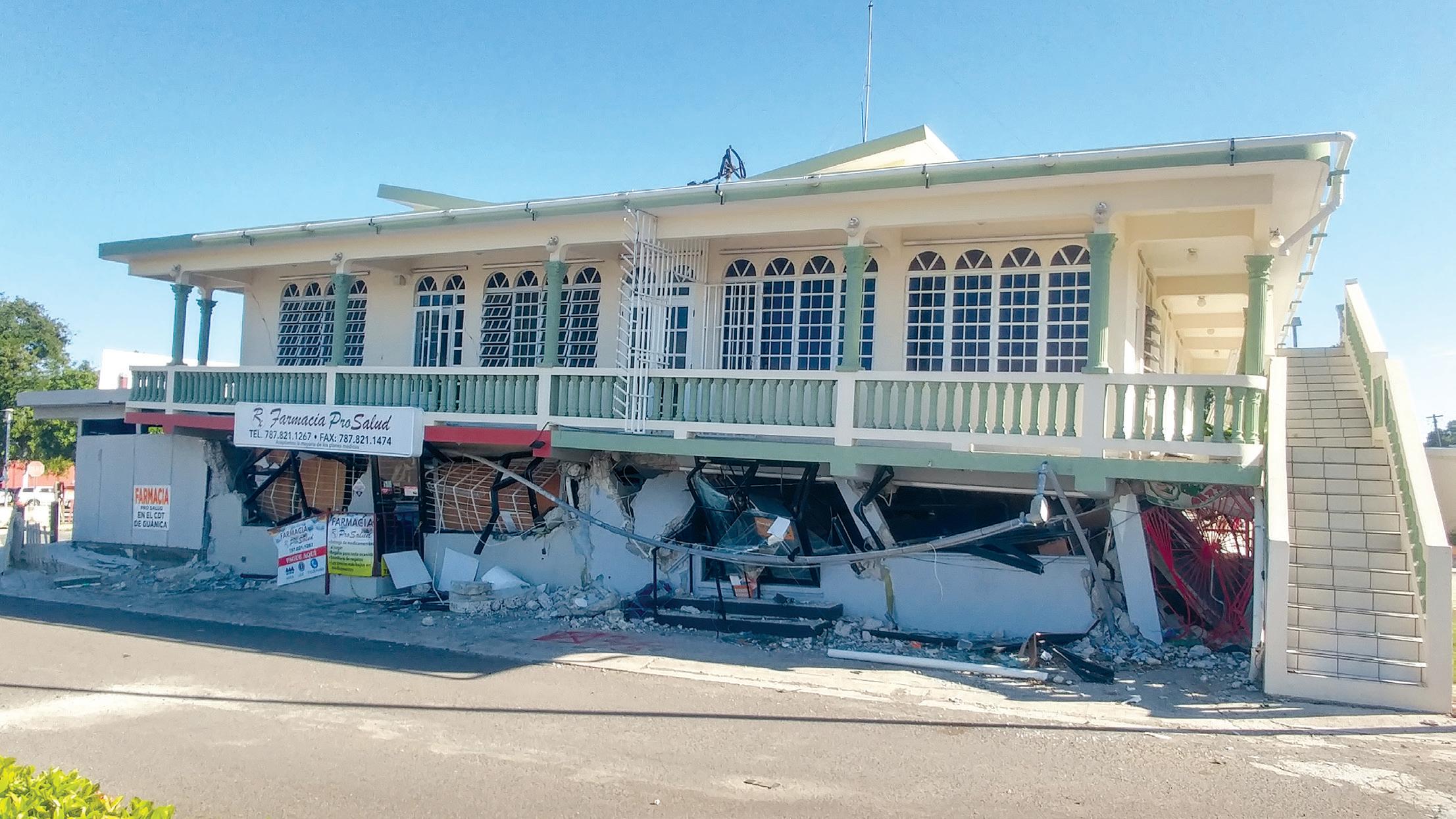
This soft-story collapse from the 2020 Puerto Rico earthquake is representative of the life-safety hazards evaluated by structural engineers during post-disaster response.
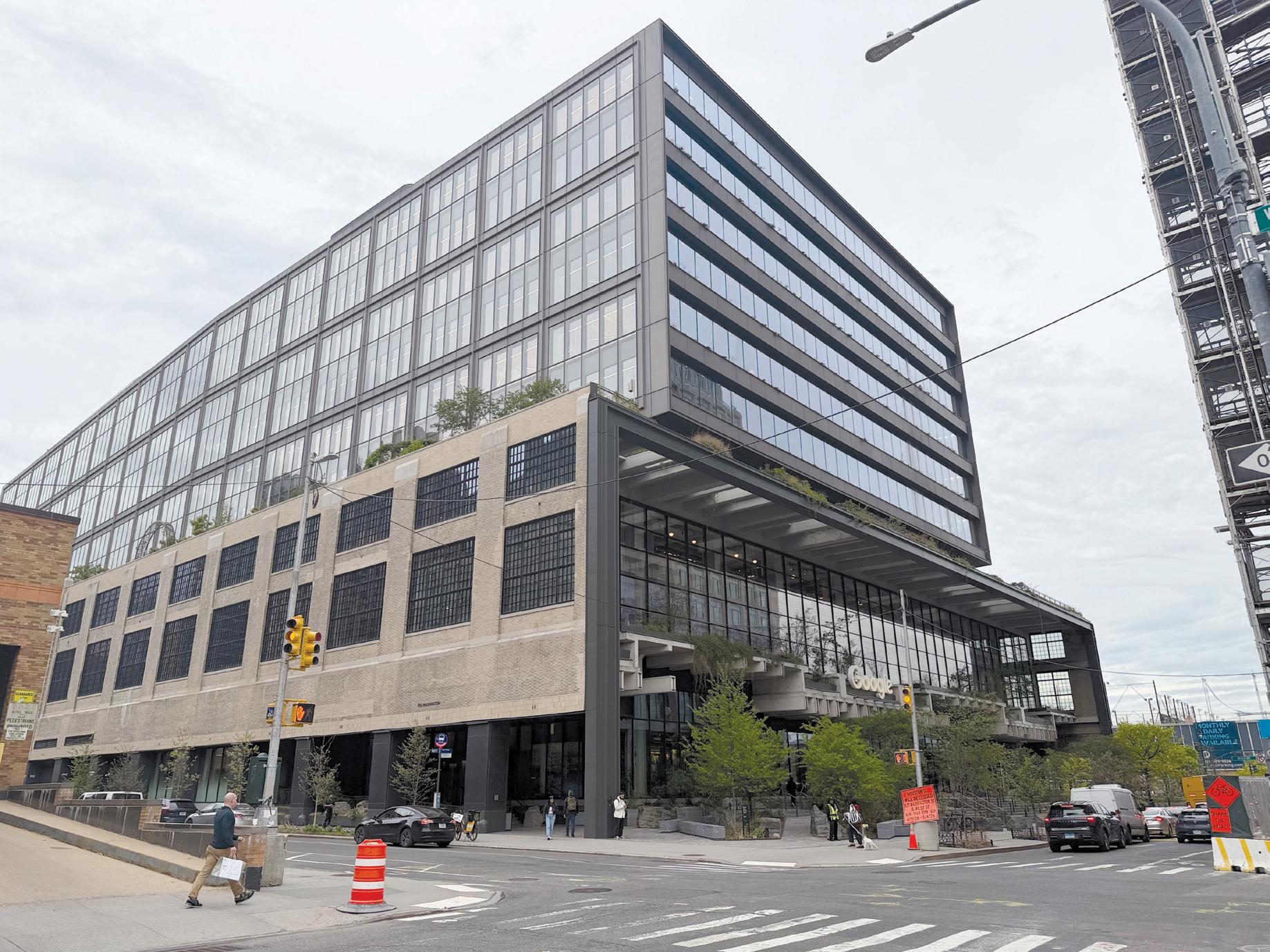
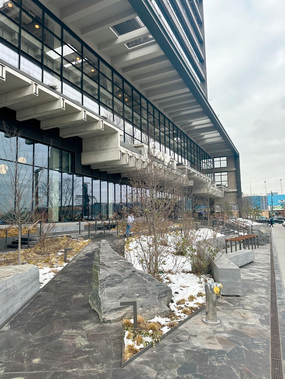
St. John’s Terminal, here facing Southwest, was converted from a rail station to office occupancy in the 1960s and most recently underwent additional renovations to become Google’s new headquarters.
Transforming Historic St. John’s Terminal into Google’s NYC HQ
Using structural bridge design principles, the retrofit enabled a vertical expansion adding nine stories above the original structure.
By Stephanie Berrios, PE, in collaboration with Dave Douglas, PEng, David Stevenson, PEng, & Barry Charnish, PEng
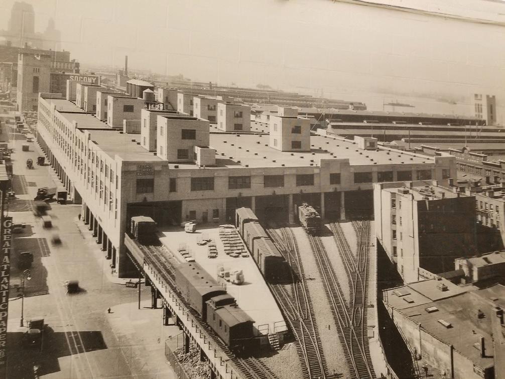
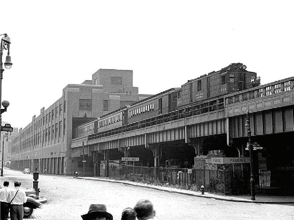
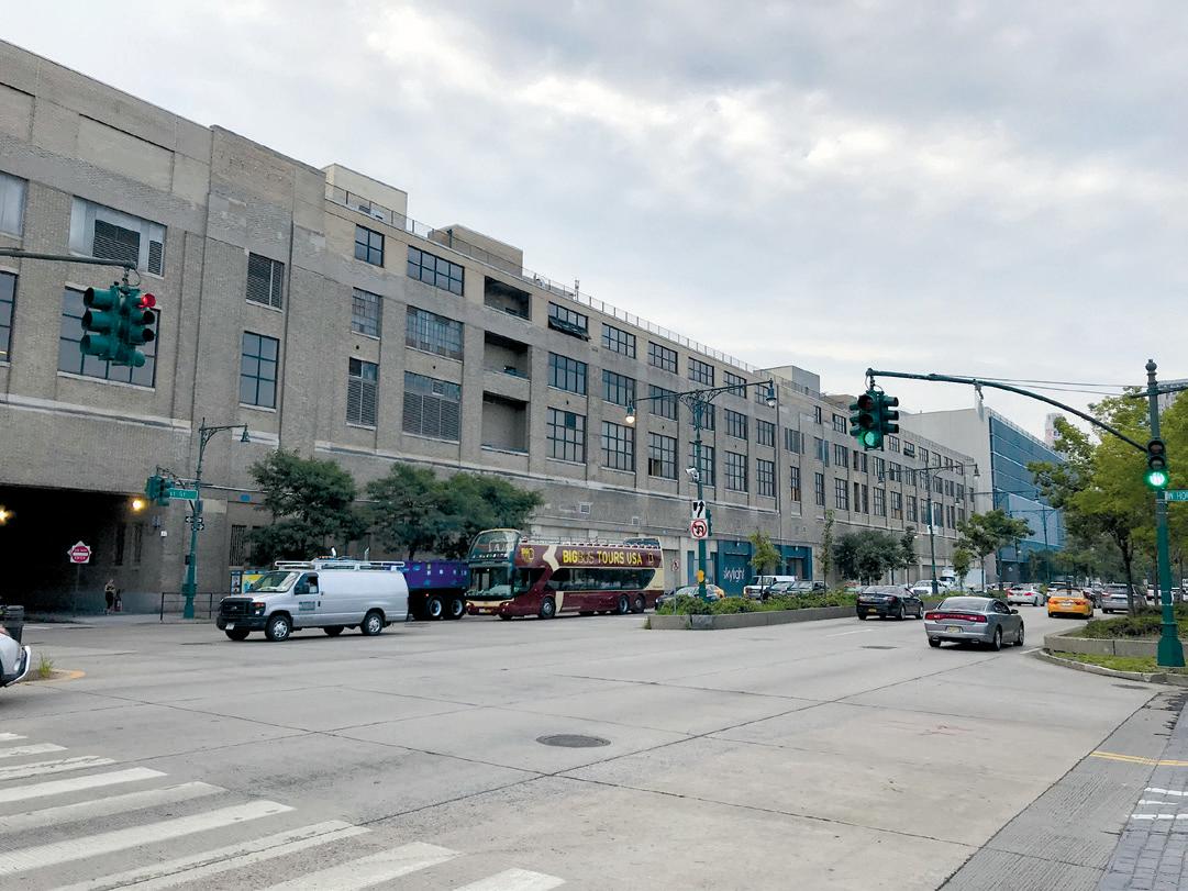
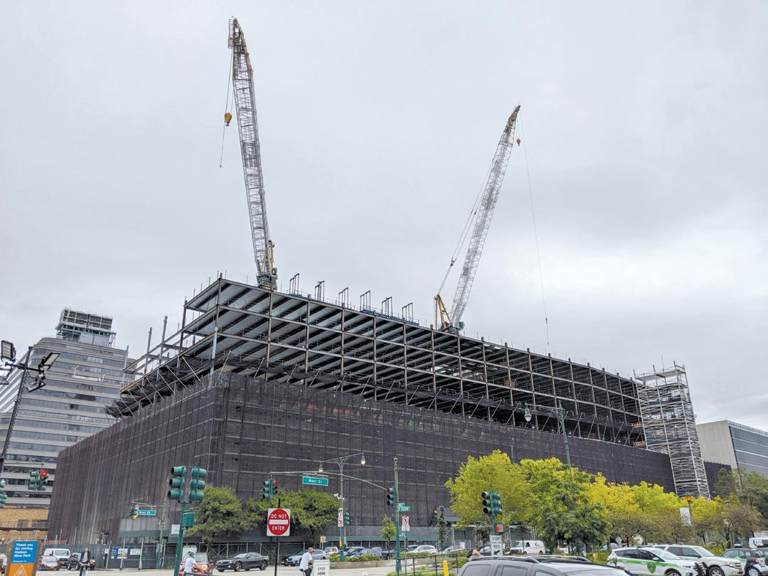
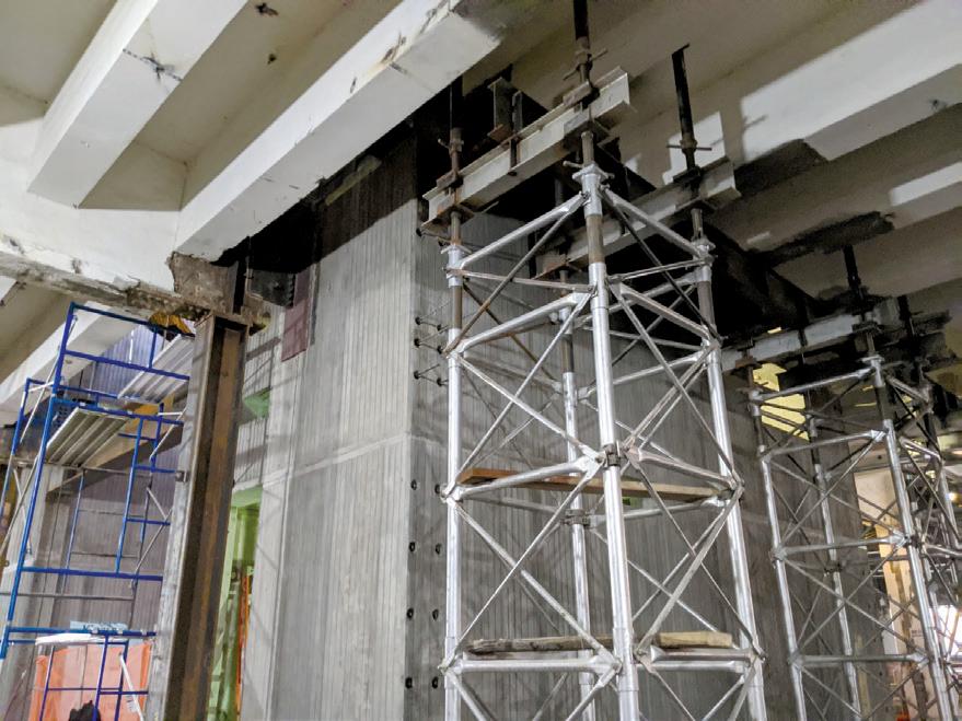
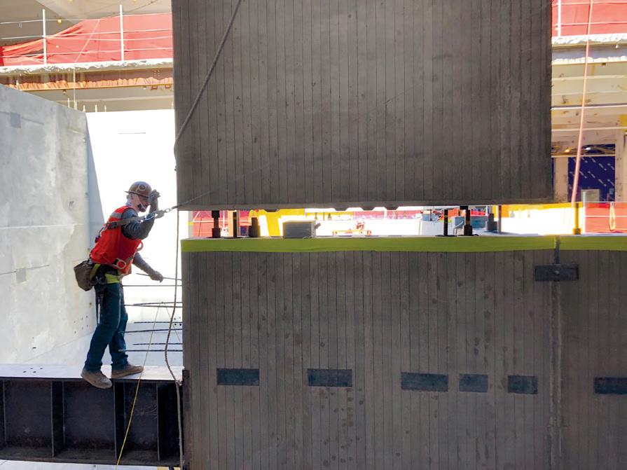
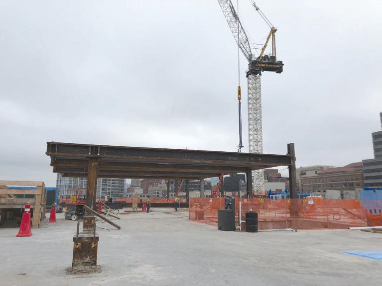
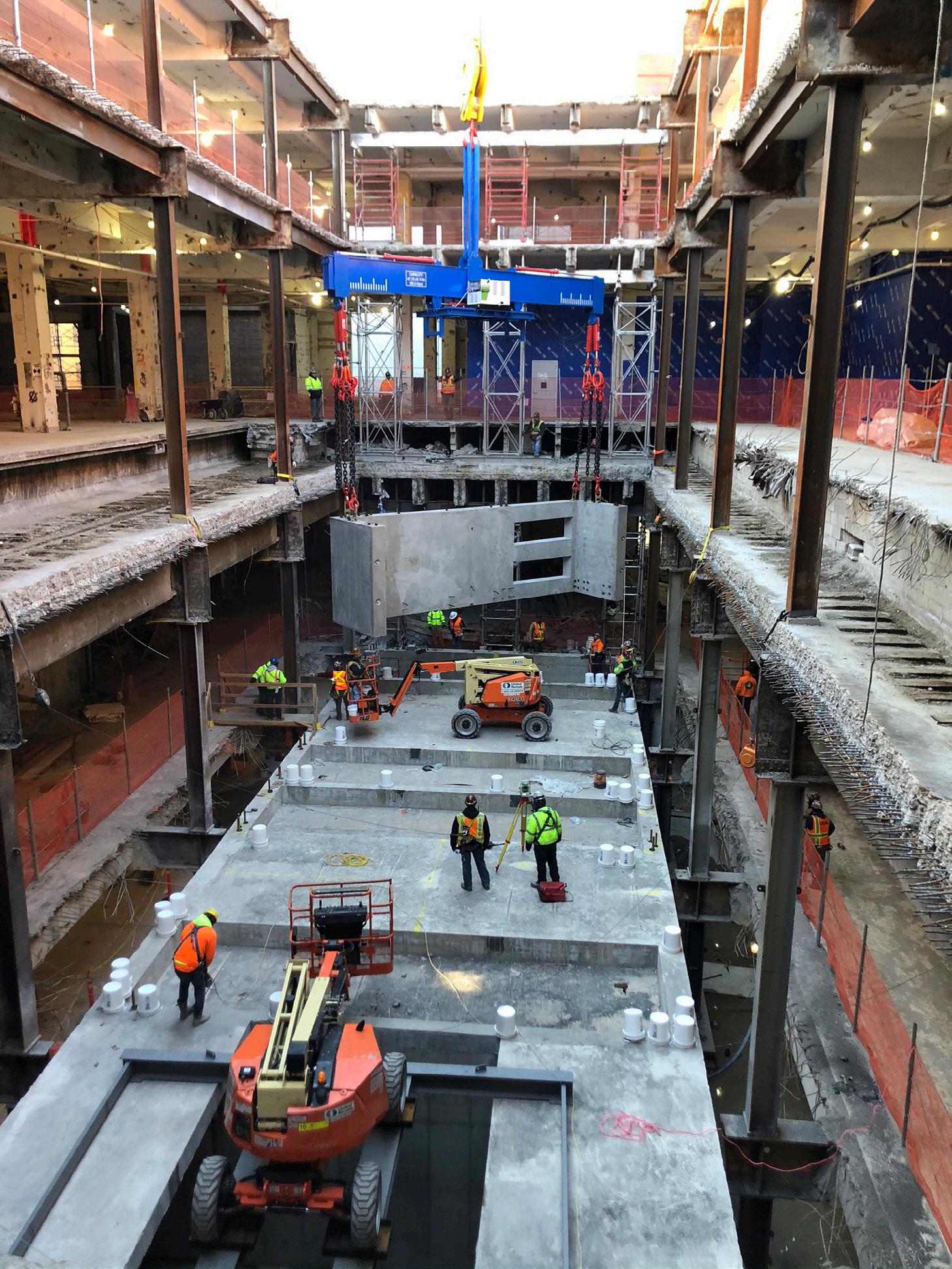
St. John’s Terminal, with three floors of 205,000 square feet each, had the largest floor space in New York City when completed in 1934 (Fig. 1). This freight-focused building, adjacent to the Hudson River, connected to the High Line elevated rail tracks on Manhattan’s West Side at 550 Washington Street and provided storage capacity for 227 train cars (Fig. 2). All floors were designed to withstand a live load of 300 pounds per square foot (psf) in addition to train loads, a specification that would enable innovation nearly nine decades later when the building was transformed into Google New York Headquarters at St. John’s Terminal. A variety of structural design strategies were instrumental to the successful redevelopment, which added nine stories above the original structure. The most notable involved leveraging structural bridge design principles, typically used for horizontal spans, to enable a vertical expansion, while preserving the character of St. John’s Terminal.
Fig. 1. Shown here is an overhead view of St. John’s Terminal during railroad operations (facing southwest).
Fig. 2. Historically, St. John’s Terminal, shown here looking up from Washington St. (facing south), connected to High Line elevated train tracks.
Changing with the Times
After a steady decline in rail freight following World War II, the High Line ceased service to St. John’s Terminal and was eventually transformed into a public park. Constructed with substantial structural strength and generous open spaces, the Terminal was repurposed in the 1960s for office and warehouse use, accommodating a range of commercial tenants.
In 2016, Cookfox Architects completed an Urban Land Use Review Procedure (ULURP) study that established a framework for redevelopment, including the potential for vertical expansion while preserving the building’s historic character (Fig. 3).
Engaging in discussions with the ownership team, Entuitive was retained in 2017 to better understand the building and inform a future design strategy. What began as preliminary investigations and feasibility studies ultimately evolved into a full structural design for a vertical expansion.
A base design for a commercial office redevelopment was developed, and construction commenced prior to Google’s acquisition of the
property in 2021 (Fig. 4). With construction already underway, the design was further refined to meet Google’s programmatic needs while maintaining an aggressive schedule. Through close collaboration between the design and construction teams, the building was completed and occupied in February 2024.
Phase 1: Investigations Into the Existing Structure
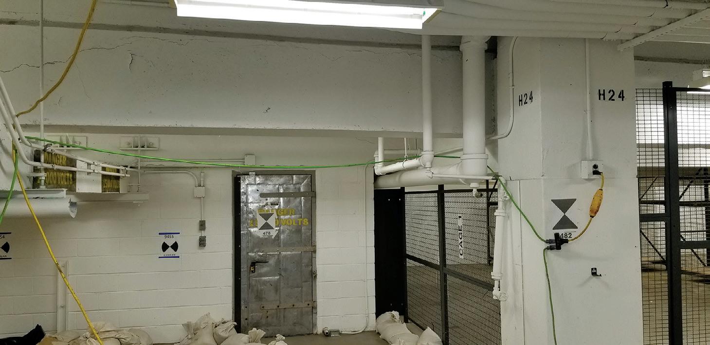
Understanding the existing structure was critical to unlocking its potential for vertical expansion. Original structural drawings were incomplete, requiring a combination of archival research, field investigation, and testing to establish a reliable structural baseline.
The team conducted extensive on-site investigations, including:
• Review of available historic drawings and records.
• Review of 3D laser scanning output completed by others to document existing geometry and framing layouts (Fig. 5).
• Structural condition assessments to evaluate
deterioration and material performance.
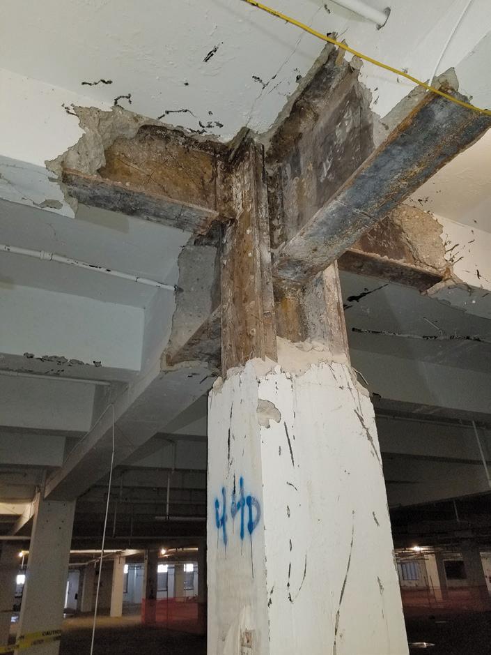
• Probes to evaluate existing connections (Fig. 6).
Where gaps in information remained, supplemental material testing was performed:
• Concrete core samples were extracted to determine in-place compressive strength, which was found to be on the order of 3,000 psi, and whether any deterioration had occurred due to the presence of diesel locomotives.
• Steel coupons were obtained to verify material properties and assess chemical composition.
These efforts confirmed that the existing structure, composed of steel framing encased in concrete supporting reinforced concrete slabs, retained significant capacity consistent with its original heavy industrial design.
Existing Structure
The original terminal structure consisted of a four-level podium framed with steel columns and steel beams encased in concrete, supporting
Fig. 3. St. John’s Terminal’s condition in 2014 was examined through a Urban Land Use Review Procedure.
Fig. 4. Two tower cranes install and erect the steel framing following core installation.
Fig. 5. Onsite 3D laser scanning, shown here in the cellar level, documented existing geometries and framing layouts.
Fig. 6. Exploratory probes extract steel coupons to aid in understanding existing connection capacities.
reinforced concrete slabs approximately 5 to 7 inches thick with beam spacings of 6 to 7 feet.
The structure was supported on caisson foundations socketed into bedrock, typical of early 20th-century heavy construction. Designed for rail loading, the system’s 300 psf capacity far exceeded modern office requirements, providing a strong foundation, both literally and structurally, for redevelopment.
Leveraging the Existing Overbuild
Designs for commercial office spaces typically target live loads of approximately 50 psf. In contrast, the original design of St. John’s Terminal could withstand loads of up to 300 psf. Leveraging this existing capacity eased the challenge of significantly increasing the building height.
The existing structure was able to support the addition of eight new office floors above the original podium. The podium roof was converted into an occupied floor, and a new roof level was introduced above the overbuild, resulting in a nine-story vertical expansion. Structural modifications were localized rather than applied broadly across the building, avoiding the need for extensive strengthening across the entire building. Reinforcement of the existing framing was primarily required in areas with increased demand, including:
• Areas with increased mechanical loading.
• Zones where framing was modified to accommodate cantilevered terrace areas and double-height spaces.
• Locations incorporating new architectural features such as skylights, terraces, and exposed rail beds.
Localized strengthening measures included the addition of steel reinforcement plates and welded WT sections to increase the flexural capacity of existing beams. In areas where demands exceeded the capacity of the original framing, particularly at terrace locations, existing members were removed and replaced with new steel girders designed to transfer loads to existing supports with sufficient reserve capacity.
The strength of the original system also enabled selective column removal within the footprint of the overbuild, allowing for open and flexible floor plates aligned with modern office needs (Fig. 7). These removals were achieved through the introduction of transfer elements, including built-up plate girders at the fifth floor, which redistribute loads from the new structure above to align with the existing column grid below.
Gravity loads from the overbuild are
supported by the continuous precast core system and a limited number of column lines, enabling clear spans of approximately 34 to 50 feet. At the perimeter, these column loads are transferred through a cantilevered transfer girder system at the fifth floor. These builtup plate girders redistribute loads from the new structure above to align with the existing column locations within the podium below, maintaining compatibility between the new and existing structural systems.
Turning Structural Design on Its Head
Necessity breeds innovation. A structural retrofit of a nearly century-old building under an accelerated schedule required creative approaches to structural design.
Recognizing that the increased building height would introduce significant lateral load demands, several structural systems were evaluated during preliminary studies, including cast-in-place concrete cores, steel braced frames, and SpeedCore systems (which are prefabricated steel panels filled with concrete). The selection process ultimately centered on how effectively each system addressed the following criteria:
• Aesthetic compatibility with the architectural vision for exposed interior elements.
• Constructability, safety, and schedule, particularly given limited staging space and the need to advance new construction while restoration work continued within the existing podium.
• Transportation and logistics, including the ability to efficiently deliver and erect materials in a constrained urban site.
• Compliance with the current New York City Building Code without requiring extensive retrofitting of the existing structure.
To maximize these benefits, the design team proposed an innovative solution: the use of segmental precast, post-tensioned concrete walls in a vertical building application, a system more commonly associated with bridge construction. The concept draws from Entuitive’s design of the Manhattan West Platform, where post-tensioned precast box girders span long distances over active rail tracks, minimizing disruption below. At St. John’s Terminal, this concept was reinterpreted by rotating the system 90 degrees. Instead of spanning horizontally, precast, post-tensioned concrete core walls were introduced within the existing building by cutting openings through the podium floors and extending the cores continuously up from new foundations below, through the existing structure, and into the overbuild above. These elements act as vertical load-bearing and lateral-resisting components within the building (Fig. 8).
Fig. 7. Shown is a typical overbuild floor plan with reduced column lines and open spans.
Fig. 8. The typical core plan layout is shown. The precast concrete walls are highlighted in yellow, green and red, corresponding to the three different mold types used to cast the walls.
Precast concrete walls
ing structure, and support large open spans.
These cores serve dual structural roles:
• Gravity system: supports loads from both the new floors and areas where existing columns were removed (Fig. 9).
• Lateral system: functions as shear walls that resist wind and seismic forces for the expanded building (Fig. 10).
Core sizes were influenced not only by structural demands, but also by elevator
The increased height introduced new lateral demands. After selectively demolishing and temporarily supporting the existing framing at the core locations, new mini-caisson foundations were installed beneath the cores (Fig. 11). Cast-in-place starter walls were then constructed to align the precast system with these newly installed foundations.
The existing steel framing was then reconnected to the cores using extended shear tabs bolted to the existing beams and welded to cast-in plates within the precast core walls. Coordination of these embedded plates with the post-tensioning tendons and reinforcement
was critical to avoid congestion and ensure constructability.
This approach allowed the new structural
Figure 9. This typical core elevation shows where precast segments or lifts (indicated at right) are different from the floor-to-floor heights (indicated at left).
Fig. 10. Shown is an overview of two precast cores (red dotted boxes) in the full building, spanning from the existing podium up through the overbuild.
Fig. 11. Temporary shoring supports the existing structure at core opening.
Figure 12. A precast segment is lifted horizontally from a truck to the tilt table on the right.
system to integrate with the existing structure while establishing a continuous and code-compliant lateral load path through the building as well as leveraging the inherent strength of the existing building. It also enabled parallel construction activities, with steel erection for the new floors progressing simultaneously with restoration work within the existing podium. Additional efficiencies were realized in construction logistics. The tower cranes used for steel erection also were utilized to lift the precast core segments into place, minimizing the need for additional equipment and reducing on-site storage requirements (Fig. 12). The use of a single trade to install both steel framing and precast core elements further streamlined coordination and communication.
Core wall segments were transported horizontally and erected vertically using custom tilt tables, installed on top of the original podium roof. The crane lifted each segment onto the tilt table, which rotated the wall segment into its vertical position for final placement (Fig. 13).
Coordination was equally critical during design and fabrication. To accommodate transportation constraints, including load limits for crossing the George Washington Bridge (which spans the Hudson River between Manhattan and New Jersey) and dimensional restrictions for truck transport, core segments were designed within allowable shipping limits. As a result, segment heights did not always align with floor-to-floor elevations, requiring careful detailing where floor beams and girders framed into the cores. Temporary steel frames were used during transportation and lifting to prevent temporary load cases from governing reinforcement design and to reduce congestion of embedded components.
Construction analysis was performed to evaluate stresses during transportation and lifting, as well as long-term effects such as creep, elastic shortening, and alignment tolerances. Sequenced erection analysis also was used to monitor deviations from vertical alignment and inform shimming and steel framing installation to ensure proper fit-up between the core system and surrounding structure.
The project team’s prior experience with posttensioned precast systems on Manhattan West proved instrumental in successfully adapting this approach to a vertical application, enabling the realization of a first-of-its-kind structural solution.
Transfer Systems and Cantilevered Design
Steel built-up plate girders were strategically introduced at Levels 4 and 5 to facilitate architectural features and structural load transfer.
On the fourth floor along the north side, plate girders support cantilevered areas enabling the creation of skylights and green terrace spaces while maintaining an open floor below (Fig. 14).
On the fifth floor, which functions as a transfer level, plate transfer girders support new column lines of the overbuild (Fig. 15).
The perimeter columns from the floors above terminate at this level and bear on the ends of these plate girders. These transfer girders are supported by column lines that align with the existing structural grid below, allowing loads from the new structure to be redistributed and delivered to existing columns within the podium. In this way, the transfer system reconciles the mismatch between the new column layout and the constraints of the original building.
This strategy enables a column-free terrace level on the fourth floor while maintaining compatibility with the existing structural system below.
Foundations and Load Transfer
The existing structure was supported on caisson foundations socketed into bedrock. By maintaining comparable gravity loads, these
foundations were largely sufficient for reuse without extensive modification.
However, the original structure lacked a clearly defined lateral force resisting system capable of supporting a taller building. To address this, the newly introduced precast, post-tensioned concrete cores, functioning as reinforced concrete shear walls, provide the primary lateral force-resisting system for the combined structure, extending continuously from the new foundations through the podium and into the overbuild above.
New mini-caisson foundations (small-diameter drilled caissons) were installed beneath the cores to support the new lateral demands. These mini caisson foundations:
• Include rock sockets with a minimum length of approximately 15 feet.
• Utilize steel casing and threaded reinforcement.
• Transfer loads through a reinforced transfer plate with couplers (Fig. 16).
To satisfy updated FEMA map flood requirements and account for the building’s proximity to the Hudson River, a reinforced 1 foot, 6 inchthick concrete pressure slab was constructed above the existing 1 foot, 6-inch foundation mat slab. This slab resists hydrostatic uplift and integrates the new foundation elements into the overall system.
Fig. 13. A core segment is set in place.
Fig. 14. The north side of the building features skylights and green spaces. Exposed track-bed structure highlights the Highline history.
Fig. 15. Fifth floor transfer girders supported by new columns below are aligned with the existing podium column locations.
Transfer girder
Location of overbuild column
Vault Relocation
When St. John’s Terminal was converted from rail use to office occupancy in the 1960s, a large electrical vault, approximately 35 feet by 100 feet and weighing 900 tons, was constructed to support building operations.
For the redevelopment, the vault location conflicted with the new architectural program on the 4th floor, particularly for the green, open spaces. A controlled jacking scheme was developed to lower the vault as a single unit by two floors and shift it horizontally into a new position. This operation required careful location.
This operation resolved spatial constraints, enabled the creation of a new mechanical level, and allowed for early activation of building systems, supporting an accelerated construction schedule.
Conclusion
In a risk-averse industry, opportunities to implement first-of-their-kind structural solutions at this scale are rare. For St. John’s Terminal, the willingness to embrace
tion, St. John’s Terminal continues to evolve, demonstrating how thoughtful structural engineering can extend the life and relevance of existing infrastructure for generations to come.■
Stephanie Berrios, PE, is a structural engineer committed to strengthening her home city through her work and mentoring the next generation of engineers through SEAoNY. Having grown professionally at Entuitive, she co-founded Adhart to continue blending technical expertise with her passion for New York City.
Fig. 16. Components of the new mini caisson.
Fig. 17. A segmental precast concrete wall, a concept typically used in bridge construction, is lowered into place at the St. John’s Terminal/Google Headquarters.
WARP 10 Structural Design of a cGMP Manufacturing Facility Using Mass Timber
By Paul Constantini, PE, SE (AZ, GA, ID, IL, NV) and Taryn Napolitano, PE
In Star Trek, Warp 10 represents the theoretical speed limit of the universe. United Therapeutics (UT) adopted the name for its newest North Carolina project, WARP10, signaling an ambition to push the boundaries of sustainable design and construction. While the facility does not bend space and time, it aims to achieve something unprecedented in the life sciences sector: to realize a Current Good Manufacturing Practices (cGMP) pharmaceutical manufacturing plant built largely from mass timber and designed to approach zero carbon. The project is defined by four primary objectives: maximize manufacturing throughput, meet cost targets, deliver an operational facility by 2027, and achieve both net zero operational carbon and net zero embodied carbon. The 196,000-square-foot facility includes manufacturing, warehousing, laboratory, office, and central utility plant.
From the outset, UT prioritized sustainable material selection. The resulting hybrid structure combines mass timber with steel framing, incorporating green steel, low-carbon concrete, organic cladding materials, and rooftop photovoltaic systems. Traditional cleanroom systems and finishes are used within the manufacturing environments to meet stringent operational requirements.
Site and Context
The 12-acre site within Research Triangle Park is surrounded by mature trees and pedestrian walkways. The building responds directly to this setting, expressing UT’s sustainability ethos through the use of mass timber framing, timber curtain walls, and Shou Sugi Ban charred Accoya wood siding.
Code Considerations
The project was designed under the 2018 North Carolina Building Code which references ASCE 7-10 Minimum Design Loads for Buildings and Other Structures. This version of the International Building Code
(IBC) provides very limited guidance for mass timber. Although wind controls the building’s lateral design, seismic requirements required special attention because ASCE 7-10 does not list mass timber frames as recognized seismic force resisting systems. Selecting an appropriate R (response modification) value therefore required careful evaluation. The 2018 North Carolina code also references the 2015 National Design Specification (NDS). However, the 2018 NDS, which was the latest code available at the time of design, was used to take advantage of its more current and comprehensive provisions for mass timber. The provisions from the 2021 IBC for special inspections were utilized for the mass timber construction.
Foundations and Substructure
Site preparation required demolition of an existing building and parking lot. Subsurface conditions included residual soils and shallow weathered rock, with approximately 50 feet of slope across the
Fig. 2. This isometric of the building structure shows which material was used in each sector of the building. Mass timber is shown in brown and steel is shown in black.
site. Blasting was required on the eastern edge, with fill placed on the western portion (Fig. 1).
A ground improvement system using rammed aggregate piers increased allowable soil bearing pressure to 6,000 psf, reducing the volume of concrete required and supporting the project’s carbon reduction goals. Rock anchors were introduced to provide uplift resistance at steel-braced frame locations.
Concrete mix designs were optimized to minimize embodied carbon, incorporating Type 1L cement, fly ash, slag, and CarbonCure technology, which injects CO2 during production to reduce overall carbon footprint.
Program Organization
The building is organized into four primary components: the central utility plant, manufacturing area, office space, and warehouse/lab areas (Fig. 2).
Central Utility Plant (CUP)
The two-story CUP anchors the western side of the facility and supports all manufacturing utilities. Due to operational demands, it is primarily steel-framed. The second floor consists of steel wideflange beams supporting a composite concrete slab on a metal deck. The low roof of the CUP contains a very large cooling tower and screen wall supported on a steel-framed platform with posts to the low roof steel. The roof framing consists of steel beams supporting an untopped metal roof deck. Horizontal steel angle diaphragm bracing is provided in the roof’s plane to enhance the diaphragm capacity due to the heavy mass of the cooling tower. The high roof over the CUP consists of wide-flange steel beams supporting 3-ply, 4-1/8 inch thick CLT roof panels (Fig. 3).
Lateral wind and seismic forces are resisted by conventional concentric steel braced frames. In order to meet the carbon goals of the project, steel was carefully sourced from mills with the capacity to meet the EPD
performance criteria required for the project. The majority of wideflange steel sections sourced for the project were produced by Gerdau Long Steel North America at their Petersburg, Virginia, steel mill.
Manufacturing Area
The manufacturing zone is a two-story, high-volume space containing cleanrooms, clean utilities, and extensive MEP infrastructure. The volume of the space was primarily driven by the height of the cleanroom ceilings, which ranged from 8 to 16 feet in height.
A 23,800 square foot mechanical equipment platform spans the 315-foot length of the manufacturing space. The structure for the manufacturing area is a mixture of conventional steel framing and mass timber framing. The mechanical platform consists of wide flange steel columns supporting conventional composite steel framing topped with a concrete slab-on-metal-deck. Conventional composite steel framing was chosen for the platform due to the large number of utilities and large clear spans below to service the manufacturing space. The remaining framing for the manufacturing space consists of glulam columns and beams, and a 3-ply CLT roof deck, to minimize the project's embodied carbon.
The column grid spacing approaches 54 feet, and clear heights of 35 feet were required in the manufacturing space to achieve the manufacturing program, which led to glulam column sizes approaching 20-inches square with glulam roof beams as large as 11½ inches wide by 435/8 inches deep. The exterior wall along the northern side of the manufacturing area is 35 feet tall and is comprised of 7-ply, 95/8-inch thick CLT panels. Lateral forces in this area are resisted by a combination of conventional steel-braced and moment resisting frames (Fig. 4).
Due to the project's warp speed, trade partners were brought in early to assist the design team. Nordic Structures was selected by the construction manager DPR to provide the mass timber framing. Nordic was able to use drawings from the schematic and design development phases to estimate and reserve the wood fiber volume early, allowing the maintenance of the fast-paced construction. Approximately 150,800 cubic feet of wood fiber
Fig. 1. The overall building and site as of April 7, 2026.
was required for this project and was sourced from Nordic’s FSC-certified sustainable forest located in northern Canada. The team used glue-laminated timber for the beams and columns with cross-laminated timber for the walls, floor, and roof decks. The wood species for all timber framing is spruce-pine-fir. Most of the glulam columns and beams exposed to exterior conditions are Alaskan yellow cedar (Fig. 5).
Office Area
The office area is a 31,000-square-foot, twostory space and provides office, collaboration, conferencing, and amenity spaces. The structure in this area highlights UT’s sustainability philosophy, as it is entirely framed in mass timber. To create large open spaces, the clear spans of floor beam framing range from 38 to almost 44 feet, with girders spanning 33 feet. Glulam floor beams range in width from 9½ to 11½ inches and are 35 inches deep (Fig. 6).
The 41-inch-deep girders supporting the floor framing are dropped in the center bay of the building to facilitate space for utilities. The second floor was established at 16 feet to meet the elevation of the adjacent mechanical platform in the manufacturing bay for convenient access. Glulam columns for the office area are 11½ inches square. The second-floor framing is topped with a 5-ply, 55/8 inch-thick cross laminated timber deck. The CLT decking is topped with a 1½-inch thick gypcrete layer to provide the required STC rating for the floor. The roof is at an elevation of 16 feet above the second floor and is comprised of glulam columns and beams, and 3-ply, 41/8inch thick CLT roof panels.
Fig. 5. The front entrance into the office of the building utilized Alaskan Yellow Cedar for the exposed members.
Fig. 4. The largest span in the building is in the manufacturing north viewing corridor. The large span was necessary to span the cleanrooms in the space below.
Fig. 3. Structure of the CUP roof is shown before (left) and after utility installation (right).
Lateral loads in this space are resisted by steel rod x-bracing between the timber framing (Fig. 7).
Warehouse and Lab Areas
The warehouse area is a two-story, high-volume facility with ambient temperature and refrigerated storage. The storage warehouse has over 1,400 pallet positions, reaching a height of 26 feet. The racking is accessed by guided turret fork trucks, which necessitated flat concrete floors with an Fmin rating of 75. The roof over the warehouse and laboratory areas provides a clear height of 38 feet. The warehouse and lab areas were another location where UT’s sustainability philosophy is highlighted. Roof framing consists of glulam beams and girders supporting a 3-ply CLT roof deck. The volume of the space was primarily driven by the required number of pallet positions.
Clear spans of the roof framing vary from 31-feet to almost 44-feet with 15½ inch square columns supporting the roof. A 5-ply CLT wall separates the warehouse from the manufacturing to the north, and a 3-ply CLT wall separates the laboratory space to the east. A mechanical platform comprised of glulam beams and a 5-ply CLT floor deck is provided over a portion of the lab area to provide space for mechanical and process equipment serving both the lab and warehouse. The column grid spacing over the lab contains spans approaching 44 feet. Glulam roof beams were as large as 9½ inches wide by 355/8 inches deep. Lateral forces in this area are resisted by conventional steel chevron-braced frames and steel rod x-bracing between the timber framing (Fig. 8).
Key Challenges
The project presented several technical and logistical challenges, including column bay spacing with spans approaching 50 feet and achieving carbon neutrality goals. Compounding these was the need to design a structurally efficient building without over-designing due to carbon concerns, all while issuing structural drawings and starting construction before the internal process systems were fully designed (Fig. 9).
Concrete slab on metal deck thickness was minimized to 2½ inches concrete over 2-inch metal deck (4½ inch total thickness). This cre ated challenges with anchorage to the concrete due to the slab’s thinness. Drilled mechanical anchors had reduced capacities. In addition, the use of the building as an intensive manu facturing facility with numerous utilities and a central utility plant led to challenges of supporting heavy loads on a very thin slab and providing anchorage for numerous utilities. Heavy utilities,
Fig. 6. Shown is typical office roof construction.
Fig. 7. Rod bracing was used in areas of aesthetic importance. These areas were the office and the north viewing corridor of the manufacturing area.
Fig. 8. Typical framing sizes shown here in the warehouse area maximize allowable racking positions..
including 12-inch diameter chilled water piping and heavy mechanical equipment, had to be supported with supplemental steel framing. More than 19,000 hangers are in the manufacturing area alone for the various piping, ductwork, and electrical systems. The team created an intensive 3D BIM coordination model to layout all systems and support points prior to construction, aiding coordination among various disciplines (Figs. 10-11).
The wood’s potential to shrink prompted another major consideration in the design. The phenomenon of wood shrinkage is well understood with the biggest variable starting and final moisture content. Every connection and interface between the wood framing and the steel framing, as well as with the CLT walls, needed to be closely evaluated. Provisions were made by leaving gaps for timber shrinkage throughout the building, where beams passed through the CLT walls, and by lowering steel beams.
Water management strategies to protect the exposed timber framing were critical during construction since the timber framing is to be left exposed in many areas of the finished building. Moisture affects the wood members themselves and can impact the steel in the connections if not managed properly.
Photovoltaic (PV) arrays are located on almost every available square foot of roof space. When completed, the PV system is expected to supply more than 6 million kBtu, approximately equivalent to the capacity needed to power almost 167 average American homes over the course of a year.
This output is anticipated to provide the facility with almost 40 percent of the energy it will need over the course of a year. Meanwhile, the building design, which incorporates mass timber, low-carbon concrete, green steel, optimized insulation, and organic exterior finish materials, is expected to achieve the goal of net-zero embodied carbon for the building.
One of the larger challenges and takeaways from the project is the trade-off between cost and construction time, as well as the project's scale for adaptability.
While mass timber has a higher upfront material cost than steel, the use of timber greatly accelerated the construction timeline. The schedule gains offset some of the cost premiums, which led to a reduction in carrying costs and labor duration. The building’s large structural spans supported the accelerated construction schedule while enabling flexible, adaptable manufacturing spaces. Ttypical lab buildings utilize a 22-foot bay span for mass timber. However, due to the structure needing to be finished before the design of the process equipment, the larger spans were paramount in aiding for future adjustability and maintaining an accelerated schedule.
Cost, Schedule, and Innovation
WARP10 demonstrates how a quick schedule, advanced structural engineering, and a commitment to carbon reduction can successfully align. Early trade partner involvement, careful material selection, and detailed coordination were essential to meeting both an aggressive schedule and the project’s net zero objectives. By integrating mass timber, lowcarbon concrete, green steel, and PV systems, the design team created a manufacturing environment optimized for throughput while
minimizing the environmental impact. When complete, WARP10 will set a new standard for sustainable cGMP manufacturing facilities and support UT’s mission to deliver critical therapies with speed and responsibility. ■
Paul Constantini (pconstantini@ewingcole.com) is a principal and the director of structural engineering with EwingCole.
Taryn Napolitano (tnapolitano@ewingcole.com) is a structural engineer, also with EwingCole.
Fig. 9. The cost components of the building materials did not directly equate to the cost of the carbon. For example, concrete was the cheapest material used on site but the heaviest contributor to the carbon impact of the building.
Fig. 10. This section through the building shows only the structural and architectural components.
Fig. 11. This section through the building shows the extent of utilities required for a cGMP building. The space required for the utilities informed the spaces of the building.
High-Strength Structural Steel
REIMAGINE
Reimagine your project designs with Aeos ® ASTM A913 high-strength structural steel. Its high strength-to-weight ratio and reduced welding pre-heat requirements make Aeos an efficient and sustainable design solution. As the only domestic producer of A913 and the largest steel manufacturer in North America, Nucor can help you optimize your supply chain and reimagine your next project.
Material strength
Welding efficiency
Supply chain assurance
Creating a Concrete Skybridge Connection
One South First is an interconnected twin-tower high-rise enabled by innovative structural and formwork solutions.
By Songtao Liao, Benjamin Pimentel, Matthew Segerman, and Yu Huang
With the advancement of building technology in the past two decades, some high-rise buildings with interconnected towers through skybridges have been developed around the world for their unique iconic architectural profiles. Notable examples include the American Copper Building in New York City, Marina Bay Sands in Singapore, and Raffles City in Chongqing, China. In most of these projects, the skybridges are constructed using steel space truss systems, with members that can be hoisted into place at interconnection levels. One South First also features interconnected towers; however, unlike most similar buildings, it is constructed entirely of reinforced concrete.
Located at the original Domino Sugar refinery site along the Brooklyn side of the East River, just north of Williamsburg Bridge in New York City, One South First is a recently completed 43-story reinforced concrete high-rise building, whose main roof is 432 feet tall. A distinctive architectural feature of the building is the interconnection of the two towers with 16 skybridge floors above the 27th level, which is approximately 270 feet above the ground floor. These interconnected floors span 44 feet between the two towers. The unique architectural configuration was thoughtfully designed to maintain view corridors between the river and the inland neighborhood, while presenting a more porous skyline when seen from the East River. Concurrently, a greater number of residential apartments are positioned at higher elevations within the building (Fig. 1).
Another prominent architectural feature of the building is its contemporary crystalline facade. The building facade consists of angled white precast concrete faceted frames, onto which the glazing is mounted (Fig. 2). These precast frames also serve as sunshades, improving energy performance and reducing cooling demand. As a result of their shading function and architectural expression, the precast facade frames are substantial in size, with depths reaching up to 20 inches and widths extending up to 22 feet over a full story height. The frames are pointsupported at the slab edges of the reinforced concrete floor system, where support reactions can be as high as 21 kips. Given the size of the precast facade frames, stringent control of relative deformation is essential to maintain facade alignment and performance.
Fig. 2. Story-high precast facade is shown with the skybridge floors under construction.
Fig. 1. One South First is a 43-story residential high-rise building on the Brooklyn side of the East River.
Integrally Interconnected Structural System
In typical interconnected-tower skyscrapers, the skybridge sizes are relatively small compared to the primary towers and are often designed to accommodate movement relative to the base structures. For the One South First project, however, a sliding skybridge solution was not feasible due to the substantial number of the interconnected floors and the large size of the precast facade frame. A sliding connection would require big expansion joints along the facade, which could discontinue the architectural feature and pose difficulties to the envelope long-term serviceability maintenance. By structurally locking the towers together through the skybridge floors, the design maintains a consistent precast facade expression across the entire building, preserving architectural continuity.
The popular flat slab floor system was selected for the One South First building due to its simplified formwork, flexibility in column layout, and reduced floor-to-floor story heights. The 16 skybridge flat slab floors work integrally with the two towers as structural diaphragms and contribute to the lateral force-resisting system, which enhances the overall building stiffness. The contribution of the flat slab system to the lateral forceresisting system was explicitly considered in the structural design, resulting in more realistic structural dynamic behavior compared to assuming that all lateral loads were resisted solely by shear walls. By accounting for the lateral participation of the flat slab-column frames, the total number of shear wall piles was reduced, significantly lowering foundation costs.
From a structural standpoint, integrally connected towers can enhance overall lateral stiffness, mitigate cross-wind excitation, and improve occupant comfort at upper levels. The benefits of this integrated configuration were confirmed through wind tunnel testing. Results demonstrated that the interconnected tower system improved perception performance: the estimated 1-year return period peak acceleration at the 42nd floor is approximately 4.9 milli-g, comparing to 6.0 milli-g estimate for a similar standalone reinforced concrete tower.
Formwork Solution for Interconnected Skybridge Floors
Due to the 270 feet elevation of the reinforced concrete skybridge floors, erecting falsework from grade to skybridge levels was neither practical nor economical. Supporting the bridge floors and their associated formwork therefore became a primary challenge in the structural system selection. The constructability and cost implications of the skybridge solution also had direct impacts on building zoning, architectural layout, and overall construction sequencing. During the early feasibility study phase, the design team and the client evaluated multiple structural framing options for the interconnected towers.
After assessing construction schedules and cost efficiency, the structural design team proposed an innovative solution: story-high cast-in-place reinforced concrete transfer girders spanning between the two towers to support the 16 skybridge floors; 44-foot long precast prestressed planks were used as the formwork/platform for the story-high reinforced concrete transfer girders at the 27th floor, as well as the shore/reshore bases for the floors above.
To simplify transfer girder framing, the columns of the 16 skybridge flat-slab floors were intentionally aligned into 4 rows without sacrificing architectural apartment layout, so that the columns loads could be transferred through four parallel girders spanned between the two towers (Fig.
Fig. 3. Four parallel transfer girders span between two towers at the 27th floor (exterior girders are 48 inches wide; interior ones are 54 inches wide).
3). The parallel girders enabled the design team to utilize the interstitial space as functional mechanical space, where the exhaust and intake louvers were routed through the skybridge soffit. This eliminated the need for facade penetrations and maintains the continuity of the building’s crystalline feature.
Precast Plank Manufacture and Installation
Seventeen 44-foot-long solid precast prestressed planks were used to cover the 65-foot width of the skybridge floors. One typical plank was 15 inches deep and about 4 feet wide, with an individual weight of roughly 33 kips. The upward camber of the planks due to the prestressing was controlled to be 2 inches before erection, and mechanical openings in planks were fully coordinated prior to their fabrication. The planks were manufactured in Selkirk, New York, approximately 150 miles from the project site, then transported by truck and hoisted by tower crane to the 27th floor for installation (Fig. 4). Neoprene pads were placed between the planks and the supporting concrete ledges to accommodate relative movement between the two towers during plank installation, and windy conditions were avoided to ensure successful erection.
The planks were designed to span between the exterior column lines of the two towers. Due to the shear wall layout, no columns were located directly beneath one side of the two interior transfer girders, resulting in potentially excessive deflections under the plank ends. Temporary shores were therefore provided at the plank supports. At the time of plank installation, mechanical piping and ductwork routing would already be in progress at the podium levels, making shoring down to the foundation impractical. Instead, the vertical shores were shifted by approximately 3.5 inches at each floor to transfer the temporary plank loads from the tower edge supports back to the shear walls at the 5th floor (Fig. 5).
Transfer Girders
The precast prestressed planks served as the working platform for the construction of the four transfer girders, which support the 16 flat-slab skybridge floors above. Two rows of dowels, spaced at 5 inches on center,
Tall BuildingS Spotlight
were embedded within each precast plank and cast integrally with the transfer girders and the topping slab, allowing the planks to remain permanently in place. Nevertheless, the structural design conservatively assumed that all gravity and lateral loads were carried solely by the castin-place transfer girders, without relying on any strength contribution from the precast planks.
Following installation and stabilization of the prestressed planks at the 27th floor, reinforcement placement and construction of the transfer girders and topping slab proceeded (Fig. 6). The transfer girders linked the 27th floor slab with the 28th floor slab, which effectively formed a 65-foot-wide multi-zoned box girder. The slabs enlarge the compression/tension zones to reduce deflections and minimize reinforcement
congestion. Because of their substantial size, the transfer girders were detailed to be cast in four phases to minimize the risk of mass concrete thermal cracking and to reduce temporary construction loads on the precast planks.
The reinforced concrete transfer girders were cast monolithically with the columns and shear walls at the 27th story, establishing the initial integral structural connection between the two towers. Subsequent flat-slab floors acted as structural diaphragms, further integrating the towers into a unified structural system. Although the precast prestressed planks were allowed relative movement during erection, the completed cast-in-place concrete system ultimately achieved full structural integrity between the towers.
Fig. 4. Precast prestressed plank manufacture and installation: (left) concrete pouring for precast planks and (right) lifting precast plank with tower crane.
Fig. 5. Precast plank end support shore shifting: (above) shore shifting detail, (middle) shore location at the 25th floor plan, and (far right) shore location at the 5th floor plan.
Fig. 6. Transfer girder reinforcing is installed on top of the precast plank platform (with mechanical splice anchors to alleviate reinforcing congestion).
Deformation Control Measures
Due to the integral structural skybridge floors between the two towers and the large size of the precast facade frames at One South First, careful control of long-term differential column shortening and precast frame support deflections was essential. Several design measures were implemented to mitigate these effects:
1. Column Section Enlargement
To minimize long-term differential shortening, the column sections supporting the transfer girders were intentionally increased in size. Enlarging the sections reduced compressive stress differentials between vertical elements, thereby limiting time-dependent shortening discrepancies.
2. Strict Control of Transfer Girder
Deflection
To eliminate the need to construct floors above the transfer girder level with cambers, the total long-term deflection estimates of the transfer girders were limited to approximately 1.5 inches, in addition to satisfying the relative deflection requirements in ACI 318 Building Code Requirements for Structural Concrete and Commentary. Controlling the absolute total long-term deflections is critical to prevent differential movement of the skybridge floors, which could otherwise result in facade misalignment and serviceability concerns.
3. Optimization of Exterior Column Layout
Significant coordination was performed during the schematic design phase to align the precast facade substantial point loads near structural columns. The locations of exterior columns were strategically adjusted so that the support connections for the heavy precast facade frames were placed in close proximity to columns. This adjustment minimizes differential deformation at slab-edge supports and reduces stress concentrations within the precast facade frames. As a result, the facade caulk joint sizes were minimized, maintaining the aesthetic appearance of the architectural facade.
Special Construction Sequence Related to the Skybridge Floors
The project incorporates precast prestressed planks, precast facade panels, and cast-in-place concrete structural members. To optimize equipment utilization and minimize schedule delays, the construction sequence was carefully planned to ensure continuous and efficient progress. Owing to the massive size of the skybridge floors, two notable construction considerations warrant special attention.
Fig. 7. Space truss platform and temporary monorail for soffit facade panel installation.
Tall BuildingS Spotlight
The first relates to adjustments in the precast facade installation sequence along the inward-facing building elevations below the skybridge. Typically, facade installation at a given floor starts when concrete placement is underway approximately five floors above. Because the precast facade panels in this project were heavy, their installation required the use of tower cranes. To avoid crane conflicts and scheduling constraints underneath the skybridge floors, the panel installation below those levels was expedited. With temporary shoring provided, the inward-facing panels were fully installed before hoisting the precast prestressed planks to the 27th floor. As shown in Figure 4, the precast panels at the inward elevations were completed while the planks were being lifted into position.
The second construction specialty involved installation of the architectural soffit panels beneath the skybridge. Given the approximately 65-foot width of the bridge portion, a dedicated space truss measuring 10 feet by 66 feet was fabricated to serve as a working platform for installing the skybridge soffit facade panels. The space truss was assembled at the podium roof level and subsequently hoisted into position beneath the bridge. To allow the platform to travel between the two towers, a temporary monorail system was constructed at the 29th floor. Figure 7 presents an elevation sketch of the monorail and space truss system.
Summary
To the authors’ knowledge, One South First has the highest skybridge floors among fully reinforced concrete interconnected high-rise towers
worldwide. Located approximately 270 feet above the ground level, the 16 skybridge floors work integrally with the two towers, functioning as structural diaphragms that enhance the overall lateral stiffness of the building. Precast prestressed planks were utilized as stay-in-place formwork to support the cast-in-place transfer girders at the 27th floor, facilitating an efficient and well-sequenced construction process. Specific design measures were implemented to address the structural and constructability challenges associated with the elevated skybridge configuration. By successfully realizing the fully reinforced-concrete elevated interconnected skybridge floors, One South First demonstrates the seamless integration of architectural intent, structural performance and constructability. ■
Songtao Liao, Ph.D, PE, is a senior associate at Rosenwasser/Grossman Consulting Engineers, P.C., with over 20 years of experience in high-rise structural analysis and design. (stevenl@rgce.com).
Benjamin Pimentel, PE, president of Rosenwasser/Grossman Consulting Engineers, P.C., specializes in high-rise concrete structures. He is a past President of the Concrete Industry Board, the current president of the Concrete Industry Foundation, and co-chair of the concrete panel for the upcoming New York City Building Code cycle.
Matthew Segerman, PE, is a senior associate at Rosenwasser/Grossman Consulting Engineers, P.C., and serves as project manager for several notable high-rise projects, including the new Domino development in Brooklyn, NY.
Yu Huang, Ph.D, PE, is a senior structural engineer at Alan Margolin & Associates Consulting Engineers and Architects, with 15 years of experience.
Spotlight: Strongwell FRP Works Where Other Materials Can’t
Since 1956, Strongwell has developed hundreds of FRP structural shapes, plate, gratings, planking, railing, fencing, structural building panels, and much more, proudly made in the U.S.A. in an ISO 9001 certified, BABAA compliant facility.
The last thing engineers should worry about when designing a tall building is weight concerns for necessary rooftop structures. Cellular, radio, and mechanical equipment must often be placed on the roof, requiring shielding for protection against the harsh elements or screening to prevent them from being an eyesore. Strongwell FRP is lightweight, corrosion resistant, EMI/RFI transparent, and low in thermal and electrical conductivity, making it the ideal solution for rooftop structures.
Rooftop structures fabricated with EXTREN® structural shapes and fastened together by FIBREBOLT® studs and nuts have adorned the Orlando, FL, skyline atop 200 South Orange (formerly the SunTrust Center) since 1988. These four fiberglass turrets house antennae for first responders’ communications and have endured hundreds of severe coastal weather events in nearly 40 years of service with little maintenance necessary.
The spire of the Bank of America Plaza in Atlanta, GA, has been adorned with a 37’ tall EXTREN structure clad with DURASHIELD® 1” tongue-and-groove foam core panels since being installed in 1991. The spire sits over 1,000 ft above ground level and is designed to sustain wind pressures of 80 psf. Contained inside this structure is valuable rental space for communications antennae.
Functional-use rooftop spaces such as recreation, leisure, shopping, dining, and green roofs are growing in popularity for multi-family
housing developments. These spaces need a lightweight subflooring option that allows for drainage, bi-directional loading, is corrosion resistant, and is easy to maneuver, fabricate, and install with minimal effort and disruption to traffic and residents. To meet these requirements, DURAGRATE® molded grating was supplied for The Grand at Sky View Parc in Flushing, NY. A total of 1,500 panels were installed to support the decking and tile flooring in the expansive shared space. Other Strongwell FRP products used for rooftop applications include DURAGRID® pultruded grating and SAFRAIL™ handrail for maintenance access and platforms, SAFPLANK® interlocking decking, and SAFPLATE® gritted plate for continuous walking surfaces. ■
The 60-story 1072 West Peachtree is Atlanta’s tallest high-rise since 1992.
Tall BuildingS Spotlight
Pinnacle on Peachtree
Atlanta’s new 60-story tower soars into the skyline.
By Susendar Muthukumar, PhD, SE, and Daniel Traub, SE
1072 West Peachtree located in Midtown, Atlanta, at the southwest corner of West Peachtree and 12th Street, is the latest addition to the city skyline. Developer Rockefeller Group partnered with TVS Architects, Walter P Moore Structural Engineers, and Turner Construction to design the 60-story mixed use tower. The 1-million-square-feet building vertically integrates 224,000 square feet of Class-A office spaces, 6,300 square feet of retail, eight levels of parking with 729 spaces, 357 luxury apartments and world class amenities. The skyscraper, at an architectural height of 749 feet, is Atlanta’s fifth tallest building and the latest constructed in the last 30 years. The primary structural system consists of a cast-in-place concrete frame with concrete shear wall cores enclosed by a glass and precast facade and topped with a steel crown.
From the outset, the project team pursued a holistic design approach, integrating wind engineering, structural optimization, and interdisciplinary coordination to deliver an elevated level of occupancy, a high-performing building, and an efficient design. This article describes design and construction challenges that were unique to this building, including column layout transitions, temperature monitoring in the mat foundations, concrete outrigger detailing, occupant comfort performance, field monitoring for column shortening, and coordination with MEP systems.
Structural Overview
The floor framing systems were selected for varying functional occupancies throughout the building. The ground-floor retail, amenity at levels 10 and 20, and the office floors on levels 11 to 19 utilize reinforced concrete slabs framing to mild pan-formed beams and post-tensioned girders. This system provides flexibility for future tenant modifications and accommodates slab elevation changes using a mild steel slab instead of having post-tensioning everywhere. The parking and residential levels consist of two-way post-tensioned slabs that maximized floor to floor height while leaving the slab soffits visible, as part of the architectural aesthetic. Column layouts were coordinated with architectural and functional requirements. To transition between differing column layouts at the residential and office levels, sloped columns over five levels were introduced to accommodate the larger office bay spacing. Similarly, bay spacing transitions between office and parking levels were achieved using 60-inch wide x 96-inch deep post-tensioned transfer girders, which were strategically located within an amenity level to minimize structural and architectural impacts. The transfer beams supported 10 floor levels with column loads of 1,900 kips magnitude transferred. Steel framing above the roof conceals mechanical equipment and elevator machine rooms, while also supporting the building maintenance (window washing) system. Level 20 features an expansive 2,400-square-foot pool with a 4-foot depth that required 18- to 24-inch-deep mildly reinforced concrete slabs framing to 5-feetdeep concrete beams, typically on a 30-foot grid. The site included one level below grade basement and was constrained by adjacent roadways and existing buildings. The top of slab at the basement level was 14 feet to 18 feet below ground surface. A permanent cantilevered retention system was provided consisting of cantilevered soldier piles with embedded steel H-piles, typically spaced at 6 feet on center. A reinforced concrete shotcrete wall was installed over the lagging to serve as the permanent basement wall system. Field verification and survey measurements were critical in locating the retention system, requiring adjustments during construction to maintain alignment within the property line.
Shown is the reinforced concrete shear wall and outrigger lateral system.
At Right/Opposite Page: Three outrigger sections with design reinforcement are illustrated.
The geotechnical recommendations were to support the building on a deep foundation system bearing on rock, which was encountered in the borings at depths ranging from 16 feet to 53 feet below the existing ground surface. Drilled piers with diameters ranging from 3 feet to 8 feet were utilized with 5-foot to 10-foot socket extensions provided to resist uplift. The tower columns were founded on individual piers. The north and south shear wall cores were supported on 11-foot and 9-foot-thick foundation mats to better distribute the significant overturning demands from the shear walls. Soil-structure interaction was considered to ensure uniform settlement and to provide adequate system stiffness.
Temperature monitoring in mass concrete was a key consideration for the mat foundations. Notes were included in the structural drawings outlining contractor responsibilities for temperature control and location of thermocouples. Sixteen thermocouple locations were identified on the foundation plan for each of the two pier supported mat foundations. At each location, a set of four thermocouples was installed throughout the depth of the foundation to monitor differential temperatures during curing. The Contractor submitted a thermal control plan outlining the monitoring procedures and mitigation measures to address differential temperature conditions. During the foundation pours, the Contractor implemented the necessary precautions to ensure that the concrete placement temperature remained below 95F, the maximum curing temperature did not exceed 160F, and the temperature differential between any two monitored points did not exceed 60F.
Lateral System
The building’s reinforced concrete shear walls interconnect with coupling beams for lateral resistance. The north core extends the full height of the building with wall thickness ranging from 24 inches to 39 inches. The
south core extends up to level 20 with 24-inch and 30-inch-thick concrete walls. Over 400 coupling beams placed above door openings link the shear walls and offer higher overturning resistance to wind loads. In 18% of the coupling beams, steel sections embedded in the concrete ensure optimal lateral performance at the more heavily loaded locations. A 24-footdeep outrigger system was positioned at approximately two-thirds of the building height to further enhance lateral performance by redistributing overturning forces to perimeter super columns. This strategy allowed the core wall thickness to contribute to the project goals of increasing usable floor area without compromising performance.
The shear walls were constructed with a high-strength 10,000 psi concrete mix at the lower levels that transitioned to 8,000 psi and 5,000 psi at the upper levels. The modulus of elasticity (MoE) of the concrete mix is a significant contributor toward building stiffness, helps control drift, and enhances occupant comfort under serviceability wind loads. Factors affecting MoE include type of rock, porosity,
(Left) The concrete outrigger system enhanced lateral performance with door openings for access. (Right) The outrigger elevation is shown with section locations.
Rebar placement at the outrigger sections as seen in the field.
Tall BuildingS Spotlight
texture, hardness, water content, and mineralogy. An enhanced modulus of elasticity was specified for the project with minimum values of 6,500 ksi and 5,800 ksi for the 10 ksi and 8 ksi concrete. The project team collaborated with local concrete suppliers to obtain aggregates sourced from outside the Atlanta area, which were then batch-tested to ensure conformance with performance requirements.
Wind Tunnel & Performance Criteria
Based on building height and slenderness, performance during service level wind loads is an important aspect of structural design. A wind tunnel study was performed by RWDI wind engineering consultants based on structural dynamic properties supplied by Walter P Moore. RWDI employed the High Frequency Force Balance (HFFB) technique in conjunction with the most recent Atlanta-area wind climate model to better understand wind pressures, dynamic response characteristics, and vortex shedding effects. Damping ratios of 2% and 1.5% were used for strength and serviceability, based on building type and height. Wind tunnel results highlighted a strong crosswind building response that aligned with the wind climate directionality. Loads from the wind tunnel study were incorporated directly into the structural design, allowing for refinement of member sizes and lateral force distribution while reducing wall reinforcement for the project. Wind-induced accelerations at the top occupied floor were evaluated for compliance with the International Organization for Standardization (ISO) residential criteria. The predicted wind accelerations for the 1-year and 10-year return periods were 11 milli-g and 18 milli-g. Because these accelerations are within the corresponding ISO criteria, the building motions were deemed acceptable for occupant comfort. Torsional velocities were also estimated at the top occupied floor and observed to be well within the criteria for the 1-year and 10-year return periods.
Vertical Compensation
Relative differential column shortening is a significant consideration during design, especially for buildings over 40 stories tall. When left unaddressed, differential column shortening can cause cladding distress, affect partitions and architectural finishes, and produce uneven floors, resulting in disputes and unanticipated tenant costs. The biggest contributors to differential shortening include elastic shortening, shrinkage, and creep, with shrinkage being the largest contributor and creep being the most variable. A common rule of thumb for column shortening is 1 inch for each 80 feet of height.
In this project, long-term time-dependent behavior of the concrete structure, including shrinkage and creep of vertical elements, was evaluated based on a differential shortening analysis with results incorporated into both the design and construction sequencing. The tower perimeter columns were expected to shorten more than the core walls. To obtain level floors at the end of construction, the contractor needed to compensate for the differential shortening. The design team developed a column compensation schedule, wherein designated top of concrete elevations are matched during construction. The schedule outlined amounts by which the columns needed to be super-elevated.
The shortening of the walls and columns were monitored during construction to corroborate analysis results. The design team outlined a surveying program on the drawings with recommended survey locations and schedule for field elevation measurements. Some of the specific requirements included the contractor engaging the services of a licensed surveyor, setting up differential shortening preconstruction meetings, and submitting survey reports within seven days from the time of measurement. The field elevations were required to be reported based on surveys to be taken from a fixed, off-site benchmark. The project team then processed the surveyed column offsets with respect to the column cores to ensure acceptable tolerance (span/360). Differential
Typical column shortening estimate is shown. Notes in the design drawings said to outline expected shortening of the structural system.
shortening also impacts other trades, including the cladding consultant and MEP contractor for pipe support system attachments. The vertical pipes were designed to provide shortening, and the structure was reviewed for any increased loading that may occur. Notes were included in the design drawings to outline expected shortening of the structural system on this project. The relative shortening for the core wall was estimated at 1/16 inch per floor and the total perimeter column shortening per floor was anticipated to range from 1/8 inch to 3/16 inch per floor.
Integrated Coordination
The coordinated design required close integration across all disciplines. Coordination meetings facilitated a holistic design approach, allowing the team to align structural systems with architectural, mechanical, and construction requirements. A key coordination effort involved the interface between the concrete core and MEP systems. Designated wall zones were established to allow piping to pass
through the core walls while maintaining structural integrity. Additionally, coupling beam detailing was developed to allow routing of ducts and conduits beneath and, where feasible, through these elements without compromising performance. This integration reduced conflicts during construction and enabled a more efficient and streamlined building system.
Conclusion
1072 West Peachtree shows how a wellintegrated design approach can provide an efficient, constructable, and performancedriven design. The structural system combined high strength concrete cores with outrigger action and wind-tunnel-informed design optimization. This approach delivered a high-rise system that met strength, serviceability, and occupant comfort requirements while aligning with project budget.
Enhanced analysis methods including wind tunnel testing and time-dependent deformation studies were instrumental in refining the design and ensuring occupant comfort,
CONNECT SEAMLESSLY
TURNKEY. EFFORTLESS. UNOBTRUSIVE.
CAST CONNEX ® Diablo Bolted Splice ™ (DBS) is a cast steel fitting that enables unobtrusive field bolted splices in circular hollow structural section (HSS) members. The DBS splice connectors are offered with thin-gauge cover plates to conceal the splice, or it may be left uncovered.
Constructability Elevated
• Pre-engineered solution a vailable in sizes to fit a range of HSS members
• Affordable enough to be used repetitiously
• Designed specifically for AESS applications, making them easy for fabricators to work with
long-term serviceability. Coordination of structural systems detailing, from transfer elements and sloped columns to foundation design and thermal control measures, addressed the unique challenges posed by the building’s height, mixed-use program, and site conditions.
Proactive coordination across disciplines enabled design integration of structural, architectural, and MEP systems, minimizing conflicts and enhancing overall building performance. Construction-phase strategies such as column shortening compensation and field
monitoring further ensured floor levelness and adequate attachments of façade and piping support systems.
As urban environments continue to densify, 1072 West Peachtree serves as a model for delivering tall buildings that are efficient, resilient, and responsive to modern demands. The project stands as a high-performing addition to the Atlanta skyline, illustrating how innovation, technical rigor, and collaboration can elevate both building performance and occupant experience.
Designated wall zones were established to allowing piping to pass through, like these conduit penetrations at shear wall.
CAST CONNEX® is the industry leader in the architectural and structural use of cast steel components in the design and construction of building and bridge structures. We simplify the design and enhance the performance of structures by enabling Architects and Engineers to use cast steel connections. We offer design-build services for custom cast steel nodes and components. Our products include pre-engineered connectors that simplify the design and enhance the performance of structures.
Our pre-engineered connectors are developed to streamline design, and accelerate steel fabrication and erection in construction projects. In parallel, our design-build services for custom castings allow project teams to address highly specialized requirements, from complex geometries, to arduous loading, to improving performance at fatigue-critical connections. In every case, CAST CONNEX works collaboratively with design engineers, fabricators, and contractors to deliver reliable, buildable solutions.
Across North America, CAST CONNEX standardized products and custom-designed castings have been successfully used to improve performance and simplify construction on landmark tall building projects, including 30 Hudson Yards and PENN 2 in New York City, and TD Terrace, and CIBC II in Toronto. These projects demonstrate how steel castings can resolve
demanding structural requirements while supporting efficient construction sequencing and high-quality architectural outcomes.
As specialists in structural steel connection design and steel casting manufacturing, CAST CONNEX provides unparalleled technical expertise, educational support, and project-specific collaboration. From early concept design through construction, our team partners with project stakeholders to deliver innovative connection solutions that elevate the structural per formance of building and bridge structures.
Susendar Muthukumar, PhD, SE is a Senior Design Manager with Walter P Moore based in Los Angeles, CA
Daniel Traub, SE is a Senior Project Manager with Walter P Moore based in Los Angeles, CA.
This detail reflects the coordination to locate penetrations at shear walls.
Structural Flex: How One Girder Does the Heavy Lifting
A cantilevering transfer girder helps the corner of Houston Methodist Hospital’s new Centennial Tower float over the ambulance drive and critical underground utilities.
By Yavor Cekov, PE, Kara Hartleib, PE, and Andrew Zucker, PE
Centennial Tower, Houston Methodist Hospital's new patient bed tower, is currently under construction in the Texas Medical Center. It is slated to partially open in early 2027 and to be fully operational in early 2028. The tower is a 26-story, 420-foot-tall, pan-formed concrete moment frame with concrete shear walls as its primary lateral system. The structure also includes two basement levels, three mezzanine levels, and multiple rooftop penthouses. Page, now Stantec, led the design team, with Walter P Moore serving as structural engineer of record, and Vaughn Construction as the general contractor.
Challenges and Solutions
One significant structural design challenge for this project was the need for the northwest corner to be free of both a ground-level column and a below-grade foundation element (Fig. 1). This corner of the building houses a vehicular drive and emergency vehicle parking, as well as sidewalks and landscaping. Further complicating matters, an existing underground utility line in this vicinity must remain operational; it could not be dis turbed. To properly accommodate the architectural vision for the ground floor and existing conditions, the column supporting the northwest corner of the building’s upper floors needed to be transferred. This condition made for a long cantilevering section at the perimeter and an even greater cantilever length where upper floors slightly overhang lower floors (Fig. 2). Headspace requirements below the first elevated floor over the drive,
Project Team
Owner: Houston Methodist Hospital, Houston, Texas
Structural Engineer: Walter P Moore & Associates, Houston, Texas
Architect: Page, now Stantec, Houston, Texas
General Contractor: Vaughn Construction, Houston, Texas
Fig. 1. A column-free northwest corner was needed to accommodate the drive and ambulance parking, and to avoid the underground utilities.
Fig. 2. The northwest corner of Centennial Tower cantilevers over 50 feet. (Photo courtesy of Vaughn Construction.)
coupled with the needed transfer girder depth, prevented the use of a traditionally located transfer girder at the level directly above the drive. However, a mechanical floor a few levels higher in the building quickly proved to be a suitable location for the deep transfer girder (Fig. 3). Plans for the upper mechanical space already included a tall story height to fit equipment, and windows or vents were not needed along the west edge, making it the perfect home for a 27-foot deep, 53-foot long cantilevering transfer girder, with a correspondingly massive 68-foot long backspan that supports a transfer column of its own. Transferring the column at the backspan was also needed programmatically, and it provided a very helpful natural balance to the load on the cantilevering end, reducing uplift in the backspan.
Additional geometric challenges included a depth reduction at the end of the cantilever to accommodate a cladding setback, as well as a depth reduction in the backspan to allow an opening for construction access at an exterior hoist. The depth reduction for the cladding setback is fortunately well located with respect to maximum expected shears and moments (or, from an alternative perspective, locations of struts and ties). The location of the access opening had some flexibility, so the design and construction teams were able to coordinate a similarly favorable spot for it in the backspan.
Analysis, Design, and Detailing
The transfer girder system, which was initially sized using the analysis and design software ADAPT-PT, is composed of normal-weight concrete with a specified compressive strength of 8,000 psi. It is post-tensioned to reduce congestion and help control deflections at the cantilevering end. Although allowed to enter the transition region between uncracked and cracked behavior, i.e., “Class T” per ACI 318-14, the tendon force and profile still provide enough lift to greatly reduce net deflections. Discontinuity (D-) regions were checked outside of ADAPT-PT for deep beam behavior using a strut-and-tie model that includes the effects of the tendons and the mild reinforcing working in parallel. The tendons drape, whereas the top reinforcing extends horizontally at a constant elevation
along the top of the girder (Fig. 4). Additionally, prescriptive deep beam requirements of ACI 318 were followed.
Approximately three hundred 0.6-inch diameter, 270 ksi, ASTM A416, low-relaxation post-tensioning tendons replace what would have been a much greater area of rebar had the girder been only mildly reinforced, greatly enhancing the constructability of the system (Figs. 5 and 6). Initially, 0.5-inch diameter tendons were specified. The team at Suncoast Post-Tension suggested the 0.6-inch substitution, which reduced the total number of tendons by approximately 30 percent. This greatly helped to
Fig. 3. The perimeter frame along the west side includes an upper level transfer girder.
Fig. 4. Portions of the cantilevering transfer girder were checked using strut-and-tie modeling.
Fig. 5. Walter P Moore worked closely with Suncoast Post-Tension to determine the exact tendon layout.
Tall BuildingS Spotlight
manage congestion, especially at anchorages, even in spite of the fact that required anchorage hardware for 0.6-inch tendons is larger than that for 0.5-inch tendons.
At the controlling location (the cantilever’s first supporting column), well over half the flexural capacity is provided by the tendons. About onethird of the tendons terminate at the depth reduction in the cantilever to avoid overstressing the reduced-depth section. Tendons were stressed from both directions and anchored in multiple layers in order to fit all anchor plates. Five layers of #11 mild reinforcing rebar lie along the top of the transfer system at the controlling location, and face bars are tightly spaced in accordance with deep beam requirements. To reduce congestion, Walter P Moore set the tendon drape such that it falls completely within the outer rebar cage, below the top layers of rebar. Additionally, continuous rebar was spliced using couplers, and the construction team chose to replace hooks at ends of rebar with terminators.
Construction Sequencing
The transfer girder’s location higher up in the building means it not only has transfer columns posting down to it, but also columns below that hang from it. As a result, special consideration of the construction sequence was warranted for the lower (hanging) floors.
The hanging columns experienced temporary compression while supporting the weight of the partial structure above until the transfer girder was ready to do the work. Walter P Moore analyzed and incorporated this action into the design via staged construction cases using the structural engineering software ETABS.
The staged construction analysis also yielded the expected system deflections at various steps in the process. Vaughn Construction monitored as-built deflections throughout the construction process, which were compared to predicted deflections to ensure the structure was behaving as expected. The observed deflections tracked the predicted deflections reasonably well, especially in early stages. As construction progressed, observed deflections were smaller than predicted, likely because assumptions made in design tend to be conservative.
Temporary steel shoring and bracing was provided from the foundation level to the first elevated floor directly below the hanging columns (Fig. 7). In the backspan location, the temporary support could be placed vertically and was therefore essentially a steel column. However, at the cantilever end the temporary support had to slope to bridge the gap between the foundation location and the location of the transfer column above. As a result, it was more complex with multiple components (basically a leaning steel column with a neighboring tension diagonal to stabilize it and a horizontal strut between them just above the foundation). These temporary supports had to be kept in place until the tendons in the transfer girder had been stressed and its concrete reached an acceptable percentage of its specified strength (Fig. 8).
The tendons were stressed all in one stage not only to avoid periodically circling back to restress, which could have been difficult as construction of the surrounding intermediate mezzanine level progressed, but also to provide a sizeable lift to the transfer girder prior to removal of the temporary support. Transfer girder bottom reinforcing was sized to handle the single-stage stressing.
The project team engaged Walter P Moore’s construction engineering group to design sand jacks that sat atop the temporary steel supports and enabled a slow transfer of load to the transfer girder system above, thereby simplifying removal of the temporary supports. However, the stressing of the tendons actually lifted the cantilevering end enough to almost fully relieve the load in the temporary steel support below it even before any sand was released from the sand jack.
Additional Considerations
Because the transfer system is post-tensioned, the full height between the floor systems above and below was poured continuously without any horizontal construction joints (Fig. 9). A horizontal construction joint within a post-tensioned member, especially a joint with tendons sloping through it, could cause unwanted shears and possibly some degree of slip at the joint. Walter P Moore designed the spandrel beam within the floor system below the transfer girder to support the wet weight of concrete
Fig. 6. Careful coordination and placement of rebar and tendons helped mitigate congestion. (Photo courtesy of Vaughn Construction.)
Fig. 7. Temporary supports were required during construction. (Photo courtesy of Vaughn Construction.)
8. The temporary supports were removed once the upper level transfer girder was ready to support the load.
9. The cantilevering transfer girder is sandwiched between two floor plates.
Fig.
Fig.
Tall BuildingS Spotlight
of the transfer girder, which amounted to about 16 kips per linear foot, along with its formwork.
Considering both the cantilever and the backspan, the transfer girder system contains approximately 400 cubic yards of concrete. Such a large volume of concrete qualified as a mass concrete pour, and therefore measures were taken to ensure quality of concrete. Keystone construction created two mock up samples of concrete using the intended concrete mix. The concrete temperature was measured during hydration at several points along the depth of the mock up and temperature curve was created based on these measurements.
With the nearly 4-foot thick transfer girder system sandwiched between two floor plates, it could easily act as a massive shear wall inserted for one story within the building mid-height, causing detrimental shear reversals in the shear walls and large associated forces in the connecting diaphragms. From a lateral system standpoint, the transfer girder would ideally be isolated from the floor systems above and below it. However, some connection is needed for lateral and torsional stability of the transfer girder system itself. Also, from a constructability standpoint, it is easiest to pour the girder directly over the floor plate below and to pour the floor plate above directly onto the girder. Detailing the interfaces between the transfer girder and floor plates had to be done in such a way as to balance these conflicting concerns. The approach taken was to avoid complete isolation, but to provide light dowels at the interfaces to limit the amount of lateral shear flowing into and out of the transfer system from the diaphragms through shear friction.
Results and Outcomes
This unique transfer girder addressed the operational and architectural desire for a column-free corner at the ground floor while maintaining adequate headroom at the floor above, constraints that prevented a conventional load path. The transfer girder size, reinforcing, and location, and the associated constructability issues, created challenges for the design and construction teams alike. The successful outcome was made possible only through teamwork and careful coordination among all parties involved. ■
Yavor Cekov, PE is a design manager in the Houston, Texas, office of Walter P Moore focused on healthcare projects. Cekov was the project manager of the Centennial Tower structural scope. (ycekov@walterpmoore.com)
Kara Hartleib, PE is now a quality engineer at Walter P Moore. Kara previously served as a design manager in the Houston, Texas, office, working on a wide array of projects. Kara oversaw the design of several structural components of Centennial Tower, including transfer girders. (khartleib@walterpmoore.com)
Andrew Zucker, PE is a senior engineer in the Houston, Texas, office of Walter P Moore with a wide range of project type experience including higher education, science and technology, and healthcare. Andrew was the project engineer of the Centennial Tower structural scope. (azucker@walterpmoore.com)
Spotlight: Advanced Motion Control for Modern Structures
For over a century, GERB has been a trailblazer in vibration isolation and structural motion control, assisting engineers and architects to protect some of the world’s most demanding structures. From slender skyscrapers and long-span footbridges to monumental staircases and critical infrastructure, GERB offers innovative Wall Dampers, Tuned and Active Mass Dampers (TMD and AMD) and 3D Base Control (3D-BCS) systems that enhance structural performance, occupant comfort, and seismic resilience.
GERB Viscous Wall Dampers (GVWD) are engineered to dissipate windand seismic-induced motion through distributed, floor-height viscoelastic dampers, while GERB TMDs operate exclusively at a structure’s natural frequency.
Applications range from mitigating perceptible sway in tall buildings to reducing vibrations in long-span floors, monumental staircases, and pedestrian bridges where comfort and serviceability are critical.
GERB has further innovated existing TMD technology with its Low Friction
Rail System (LFRS) for projects with limited installation height. GERB’s TMD systems operate without hydraulic dampers. By utilizing proprietary mechanical damping technologies, the LFRS provides highly reliable motion control with virtually maintenance-free operation over the life of the structure. This makes LFRS TMDs especially well-suited for tall, slender buildings and retrofit applications where compact design, long-term reliability, and minimal maintenance are essential.
In addition to motion control, GERB is a recognized leader in seismic and vibration base isolation for both new construction and retrofit applications. Its 3D-Base Control System (3D-BCS) technology uses pre-stressable steel spring isolators and viscous dampers (Viscodamper®) below structures to reduce the transmission of structure-borne noise, vibration, and earthquake forces in all spatial directions. Through close collaboration with architects, structural engineers, and developers, GERB continues to advance vibration and seismic protection technologies for resilient, high-performance structures.
GERB Double Pendulum Tuned Mass Damper
GERB Low Friction Rail System Tuned Mass Damper (LFRS-TMD)
GERB Tuned Mass Dampers for Footfall and WindInduced Motion
structural FORUM
Stamping Out Engineering Fraud
Consistent digital workflows and enforcement are necessary to protect engineers and the general public from fraudulent use of engineering seals.
By Marshall Carman, PE, SE
As professional services are now being sold on online marketplaces, a new form of professional fraud is emerging. Licensed engineers are discovering that their names, license numbers, and professional identities are being used without their knowledge to produce and stamp design documents. While digital signatures and electronic authentication laws exist, inconsistent adoption and enforcement have left significant gaps in the system. This article explores a real-world case of engineering impersonation, examines why current safeguards are falling short, and argues that protecting the public and the industry will require more than technology alone.
Last year, someone at my firm brought a website to my attention. It was a gig-economy website specifically for professional services. Unlike platforms like TaskRabbit, which connects people with gig contractors willing to assemble furniture or mount a TV to a wall, this service aims to connect people and companies with professionals willing to do “white-collar” freelance work like programming, graphic design, digital marketing, or architecture and engineering services.
The Problem
The colleague who brought this to my attention had discovered that his license was being fraudulently used to sign and seal structural drawing and calculation packages. He found this out when he received a call from a contractor trying to get a question answered about project documents. For a project that my colleague knew nothing about.
This wasn’t a case where they had lifted my colleague’s signature and seal from a set of drawings. The scammer simply obtained his name and license number from the state board’s website, made their own digital stamp, and added a messy signature that had no resemblance to my colleague’s.
When the contractor attempted to get a hold of the individual he thought he hired, and could not reach anyone through the website he had originally used, he went to Google and found the name he was looking for on our company website and found the real engineer instead. After the initial confusion and concern, they reached out to the local authority having jurisdiction and the state board to report the issue.
The Verdict
After the board’s investigation, it was determined that the homeowner, the contractor, and my colleague were all victims of fraud (i.e. it was not determined that the contractor was complicit or had reason to know that he was procuring illegitimate engineering services). By
Definitions
Electronic Signature: A broad term referring to any electronic process that indicates authorship, approval, or acceptance of a document. An electronic signature could simply involve applying an image of your signature to a document. Electronic signatures wouldn’t necessarily have to include any type of security and could be easily scanned or reproduced.
Digital Signature: A type of electronic signature that uses encryption and is tied to a Digital Certificate. The application of a digital signature may include meta data of who signed a document and when the document was signed. A digital signature can also verify the integrity of the document by detecting if the document is changed after the signature is applied.
Digital Certificate: An electronic file that serves as a unique digital fingerprint that links an identity to a public key. This can be used to prove that a digital signature belongs to the identity signing a document. Certificates can be “self-signed” or issued by a 3rd party Certificate Authority (CA). However, a certificate provided by a trusted 3rd party Certificate Authority would be required to prove that the digital “identity” is actually you, and not someone claiming to be you.
the time the investigation started, the scammer no longer had an account or persona on the platform. My colleague eventually found out that this scammer had fraudulently used his license number for a couple of other projects before disappearing. It is possible that the actual number of projects completed with his license number could be much more than what was discovered.
Unfortunately, this is not a unique story, and it’s something that states are being watchful of and are putting out communication about. Code officials that I work with in Ohio reported similar stories. The Alabama State Board for Licensure for Professional Engineers and Land Surveyors has a Fraud Alert notification on their home page. The notification highlights the rise in online scams where individuals impersonate licensed engineers and provides tips for identifying warning signs of fraudulent practices. The Oregon State Board of Examiners for Engineering and Land Surveying’s latest newsletter includes a “Protect the Public & Be Aware” notification describing this issue, and providing recommendations for engineers.
The Solution
A technology solution already exists: Require the use of digital signatures by designers to confirm documents are valid and require the use of a trusted certificate authority to confirm the person signing and sealing the documents are who they say they are. In fact, almost all states already have laws like the following in the Ohio Administrative Code:
Rule 4733-23-01 Paragraph D
Plans, specifications, plats, reports and all other engineering of surveying work product bearing a computer generated seal and electronic signature and date shall have an electronic authentication process attached to or logically associated with the electronic document. The electronic signature must be unique to the person using it; capable of verification; under the sole control of the person using it; linked to a document in such a manner that the electronic signature is invalidated if any data in the document is changed.
Some states are more explicit regarding digital signature requirements, and some are more vague, but in general, states require that electronic or digital signatures meet some combination of the following requirements.
• Unique to the individual.
• Capable of verification.
• Under the sole control of the person using it.
• Is removed, invalidated, or modified if the documents are modified after the digital signature is applied.
The Problem With the Solution
Digital signature technology is not new, and the Ohio law referenced above requiring the use of digital signatures is nearly 20 years old. However, except for a few states, this technology is still not universally adopted in practice, nor is the law universally enforced by building departments.
Any individual can self-sign their own certificate to create a digital signature, but this alone wouldn’t prevent someone from using someone else’s identity to digitally sign a document. You still need to ensure that the person signing the document is actually who they say they are.
Certificate Authority
One way for this technology to work is to require identity verification through a trusted Certificate Authority. Purchasing these certificates from a Certificate Authority can cost anywhere from $90 to over $700 per year per certificate depending upon the Certificate Authority and type of certificate required. While this might be expensive, I don’t necessarily believe the barrier to adoption is the cost.
I think the lack of adoption is because the process is complicated. It requires the recipient of the digitally signed documents to agree that the Certificate Authority is trusted. That means the recipient has to have the appropriate root certificates installed on their computer. While some root certificates are pre-installed on most computers, others may require a manual user installation. This may require the plan reviewers at the building department to both have the authority and the capability to manually install a root certificate into their computer’s trust store. Alternately, to avoid requiring staff to install root certificates on their computers, authorities having jurisdiction (AHJ) could simply dictate which Certificate Authorities, and types of certificates are permitted. In either case, this can create some additional
Digital signature technology is not new, and the Ohio law requiring the use of digital signatures is nearly 20 years old. However, except for a few states, this technology is still not universally adopted in practice, nor is the law universally enforced by building departments.
confusion if different states and AHJs adopt different requirements. Assuming all parties can get on board with similar standards and enforcement for digital signatures, a valid signature on the document will have a have a green checkmark or similar symbol that indicates that signature is valid. Clicking on the signature will provide additional meta-data validating when, where and by whom the document was signed.
Continued Challenges
Working with digitally signed documents still has its challenges. Changes made to the document after a digital signature is applied will remove the green checkmark and replace it with a warning symbol letting the user of the document know that the document has been modified. Modifications that trigger this warning might include combining PDFs from different disciplines into a single document, or the application of an additional digital signature by another licensed professional, or the application of a stamp by the AHJ itself. Despite state law that required the use of digital signatures for electronic plan submittal, in one case an AHJ’s own electronic submittal instructions actually prohibited the use of digital signatures specifically because it interfered with how the AHJ internally processed PDFs after they received them.
Design firms that work in municipalities and states such as Florida that do enforce their own digital signature laws have managed to make it work. It isn’t a simple or straightforward solution, but it can work if all parties agree to implement it.
What Is the Problem Again?
I believe two things have occurred in recent years that have resulted in the recent surge in engineering fraud.
1. The public has a new comfort with gig-economy workers. Whether it is ride-shares, renting vacation homes, or furniture assembly, people are more comfortable with transactional relationships with individuals they don’t know or vet providing goods and services.
2. The world is flat. It is easy for anyone anywhere in the world to offer services. This results in immensely cheaper costs for services. Unlike ride-shares, vacation home rentals, or furniture assembly, certain consulting services never require a physical presence (i.e. if site visits or live meetings aren’t required). This makes it impossible for local agencies to regulate these
services or catch criminals operating outside of the United States.
To give you an idea of what’s out there, one freelancer on one of these sites, whose bio indicates they are from the UK, offers architectural and structural engineering stamps! Their instructions and online order form state the following:
• Place your order from the list of packages based on number of pages and shipping speed.
• Submit your documents.
• They will review the documents and apply the necessary stamps.
You can compare their packages in Fig. 1. It costs $100 for stamping up to five pages, and $500 for stamping up to 20 pages with expedited delivery and additional revisions.
Rule 4733-23-01 paragraph B of the Ohio Revised Code states that “Each registrant is charged with the safeguarding of their personal seal.”
Had my colleague only ever produced work using digital signatures and ensured that his personal seal and digital signature were adequately safeguarded, it would not have prevented the fraudulent use of his license number (which is publicly available on the state’s license lookup website). The building department that permitted these documents, like most others in the state, was willing to accept drawings that didn’t meet the state’s digital signature requirements.
I don’t think the problem is the lack of safeguarding of engineer’s seal, or necessarily the lack of a digital signature. The problem is some individuals are willing to defraud others by offering plan stamping services. In some cases, we are asking the general public to be able to identify legitimate engineers from people offering plan stamping services and committing fraud.
In my colleague’s case, the public was put at risk because their contractor hired an “engineer” that the contractor didn’t know and didn’t verify was licensed and qualified to do the work they offering to perform. This fraud was committed before plans were issued for permits. Some level of research and vetting could have prevented this fraud well before it would be identified by a lack of a digital signature on the permit plans.
That is exactly what Engineers Nova Scotia is proposing. Engineers Nova Scotia created a public social media campaign titled “Verify Before You Hire” (Fig. 2). As part of Engineers Nova Scotia’s “Verify Before You Hire” program, members of the public are encouraged to contact the regulator before hiring an engineer to confirm that the individual is properly licensed. Where necessary, Engineers Nova Scotia can also verify the registered engineer’s contact information, allowing the public to confirm that they are dealing with the licensed professional. There has been national interest from Engineers Canada, and internal discussions are underway regarding the development of a national fraud awareness campaign. The goal of this program is not only to protect the public from risk associated with work being performed by unregistered and potentially unqualified engineers, but also to protect the public from the costs associated with being defrauded before plans are submitted for review.
The engineering and architecture community has some catching up to do in order to be compliant with state laws requiring digital signatures and seals on drawings and documents. Consistent digital signature workflows and enforcement is necessary when operating completely digitally with unfamiliar consultants. But submitting documents for permit is the last step in the fraudulent impersonation of an engineer or architect. Catching fraud at this point protects the public from a potentially unsafe design provided by an unlicensed individual. Stopping fraud before the unlicensed individual is hired would protect the general public and the consumer. ■
Marshall Carman, PE, SE is a structural engineer in Cincinnati, Ohio. He currently serves as Technical Director for Schaefer.
Fig. 1. Here’s an example of a freelancer’s structural engineering services and packages it offers online.
Fig. 2. Engineers Nova Scotia created a social media campaign, “Verify Before You Hire,” to encourage members of the public to contact the regulator before hiring an engineer to confirm that individual is properly licensed.
historic STRUCTURES
Alton, Illinois Bridge 1894
19th Century Mississippi River Bridges
By Dr. Frank Griggs, Dist. M. ASCE
Alton, Illinois is located approximately 6-miles upstream from St. Louis and 200miles south of the Burlington Bridge. It sits on a bluff overlooking the river with lowlands on the west side (Missouri) of the river. The shipping channel was close to the Alton side of the river but had been known to shift depending on the river flow. “The channel of the river flows at their foot at the upper and business part of the city. The river leaves the bluff about ½ mile above the bridge and at the bridge there is low ground about 1/4 of a mile in width between the low water bank and the foot of the bluffs.”
A bridge across the river at this site had been proposed for many years and in fact Col. Stephen Hariman Long had submitted a design in 1839. The Chicago, Burlington and Quincy Railroad, (CB&Q) already had bridges across the River at Burlington and Quincy and was using the Eads Bridge to cross the Mississippi at St. Louis. CB&Q did not like to be dependent on other lines and bridges with tolls and began planning a bridge of their own at Alton in 1879 with the idea of a line that ran north of the city to the west and then down to St. Louis. This would also require a bridge across the Missouri River to be called the Bellefontaine Bridge. The company used George S. Morison as its Chief Engineer. Morison was one of the leading bridge engineers in the country at the time and built many bridges over the Missouri, Mississippi, and other rivers.
The company used George S. Morison as their Chief Engineer. Morison was on the leading bridge engineers in the country at the time and built many bridges over the Missouri, Mississippi and other rivers and several for the CB & Q. He began the design without the knowledge of the citizens of Alton.
The CB &Q along with some citizens of Alton formed the Saint Clair, Madison and Saint Louis Belt Railroad Company. Their line would run from Bellville, Illinois through St. Clair and Madison Counties to the bridge. Upon crossing the bridge, it would connect with St. Louis, Keokuk and North Western Railroad, another line linked to the CB & Q, into St. Louis. The first official announcement of their plans was not made public until the spring of 1889.
The bridge company received the approval of Congress with Chapter 816, “An act to authorize the construction of a bridge across the Mississippi River at some accessible point between the mouth of the Illinois and the mouth of the Missouri Rivers” on August 29, 1890. The act stated in part,
That said bridge shall be constructed to provide for the passage of railroad trains, and, at the option of the corporation by which it may be built, for the transit of foot passengers, animals, wagons, and vehicles of all kinds, for such reasonable rates of toll as may be approved from time to time by the Secretary of War…
That if any bridge built under this act shall be constructed as a drawbridge the same shall be constructed as a pivot drawbridge, with a draw at a point accessible and convenient for navigation, and with spans of not less than two hundred feet in length in the clear Spans at pivot pier. on each side of the central or pivot pier of the draw, and the next adjoining span or spans shall not be less than three hundred and fifty feet in length, and the headroom under such spans shall not be less than ten feet above high water.
That all railroad companies desiring the use of such bridge shall have and be entitled to equal rights and privileges relative to the passage of railroad trains over the same and over the approaches thereto upon payment of a reasonable compensation for such use.
Morison submitted his location and plans to the War Department for their approval on April 8, 1891 and they were approved with the proviso “that the opening on each side of pier VII [the swing pier] should not be closed until a good channel should be established through the draw and rendered permanent by the action of the Government dike now under construction, the company agreeing to maintain the channel from the lower end of the dike through the draw.” The citizens of Alton, however, did not find out about the plans until February 10,1892 at a meeting in Alton where they saw some—but not all—of their plans. His plan was to cross the river with a swing span 454’ long providing 200’ clearance, on both sides of the swing pier, close to the Alton side
The track for Chicago, Burlington, and Quincy Railroad connected with the bridge site on the south bank of the Mississippi River and connected to Alton, Missouri.
Historic American Engineering Record (HAER) drawing of the Alton, Illinois bridge.
of the river followed by a fixed Pennsylvania Truss 350 feet long followed by six 210 feet long single intersection Pratt Trusses. The bridge was built entirely of steel. He provided the required 10 feet clearance of high water. Long wooden trestles on both sides completed the crossing. The westerly abutment was on Ellis Island with the wooden trestle crossing a small lake then down to grade. The swing span was one of the longest and heaviest in the United States at the time as it was designed to carry two tracks.
The masonry piers were set on 4-foot thick timber mats, 60 feet by 20 feet, resting on wood piles spaced three feet apart. The contractor for the foundation work was Louis Loss who started work in early March 1892 and was complete in summer of 1893. The Union Bridge Company, under Charles Macdonald, started work shortly after and by March 1894 completed work on the swing span which was first swung later in the month. The first train to cross the bridge was on April 5, 1893.
While the work on the bridge was going on Morison took steps to ensure the main shipping channel, at all water levels, was through the swing span openings. Steamboat captains made a last ditch stand against the bridge at a meeting with a Board of Army engineers on February 14,1894 in which they claimed, “the bridge company had placed the draw span on the wrong position; that the current was not there, and that not a thing should be done until the bridge company remedied the evil.” After hearing all the arguments, and Morison’s rebuttals, the Board approved the bridge, “with the understanding that the bridge company extend the dike and continue large-scale dredging through the draw.”
The bridge had a grand opening on May 1, 1894, with Morison delivering a speech he entitled, Great Engineering Achievements of the Age. The Governor of Illinois and the Lt. Governor of Missouri, attended and gave speeches.
The Old Clark Vehicular Bridge was built adjacent to the railroad bridge and opened on July 15, 1928. It was replaced by the current bridge in January1994 and demolished in August 1994.
Unfortunately, business was slow on the railroad bridge and the company went into receivership on January 16, 1897. In August 1904 the Missouri & Illinois Bridge & Belt Railroad took over the operating of the bridge. Traffic across the bridge stopped in 1988 when the line was abandoned. It was demolished in 1990. ■
Dr. Frank Griggs, Dist.M. ASCE, specializes in the restoration of historic bridges, having restored many 19th Century cast and wrought iron bridges. He is now an Independent Consulting Engineer (fgriggsjr@verizon.net).
Structural Engineering Resource
A view of the bridge looking toward Missouri shows the various truss styles.
Savills Research Identifies New York and San Francisco as Leading Hubs for Architecture and Engineering Talent; Dallas, Seattle and Boston Emerging as Key U.S. Growth Markets
Savills has released new global research examining how architecture and engineering firms are reshaping their office strategies in response to intensifying competition for talent, rising costs, evolving workplace expectations and accelerating digital transformation, with U.S. markets playing a central role in that shift.
According to Savills’ latest “Spotlight on the Architecture & Engineering Sectors,” access to talent is the most important factor shaping office portfolio strategy for A&E firms, cited by 78% of respondents. Real estate cost and talent cost follow closely behind, highlighting the extent to which firms are balancing access to specialized labor with overall cost efficiency as they evaluate where to grow and how to structure their portfolios.
The report’s Savills A&E Talent Index ranks San Francisco and New York as the top two global hubs for architecture and engineering talent. Boston, Chicago and Seattle also rank among the most attractive North American markets, reflecting their large, specialized labor pools, dense concentrations of leading firms, strong salary levels and access to worldclass universities and research institutions.
At the same time, the research points to a widening opportunity set across the United States. Dallas, Austin, Denver, Nashville, Salt Lake City and Atlanta are identified as rising North American markets gaining momentum due to lower living costs, population growth and expanding sector ecosystems. Among them, Dallas stands out as a market that combines strong access to talent with lower costs. At the same time, Seattle offers a top 20 talent profile and more competitive prime rents than those in coastal gateway markets such as New York and San Francisco. The research also highlights Boston and Dallas as U.S. markets where firms can access deep labor pools without the same salary premium as the most expensive global hubs.
“A combination of talent constraints, cost pressures, client expectations
and technology is reshaping where architecture and engineering firms locate and how they configure their portfolios,” said Rick Schuham, CEO of Global Occupier Services at Savills. “Increasingly, these firms want their offices to demonstrate environmental leadership, support more flexible and future-focused ways of working, and provide clients with a tangible example of how workplace strategy and technology can come together. Competition for space that meets those requirements in the world’s leading cities is intense, and the cost implications are significant. Looking ahead, those location and cost pressures are only expected to increase, making informed corporate real estate planning an increasingly important driver of business performance.”
The report also shows that U.S. A&E firms were more likely to expand office space in the second half of 2026 than their counterparts in other regions. Approximately 36% of firms in key U.S. markets increased their office footprint during that period, compared with 33% in EMEA and 15% in Asia Pacific. Globally, 39% of firms maintained square footage, 35% consolidated, and 25% expanded, underscoring that office strategy across the sector remains in flux.
For architecture and engineering firms, the office continues to serve a strategic role beyond mere occupancy. Savills research notes that firms are placing greater emphasis on technology-enabled workplaces that support collaboration around complex models and data, while also using office space to reinforce culture, showcase technical capability, and demonstrate sustainability commitments to clients.
The findings suggest that while legacy gateway cities remain essential for access to top-tier architecture and engineering talent, a growing group of lower-cost U.S. markets is becoming increasingly competitive as firms seek to balance hiring needs, client proximity, workplace quality and portfolio efficiency. ■
ASCE COPRI Honors Gayle Johnson for Excellence in Harbor and Coastal Engineering
The American Society of Civil Engineers’ (ASCE) Coasts, Oceans, Ports, and Rivers Institute (COPRI) honored Simpson Gumpertz & Heger (SGH) Senior Principal Gayle Johnson with the 2026 John G. Moffatt–Frank E. Nichol Harbor and Coastal Engineering Award, one of the institute’s highest honors. The award recognizes Johnson’s four decades of expertise in seismic engineering, project leadership, and contributions to advancing industry standards in harbor and coastal engineering. He will be formally recognized during the Ports ’28 Conference, which takes place in Mobile, AL, May 22-25, 2028.
Established in 1977, the award honors innovative ideas and concepts that advance engineering and construction practices for harbor and coastal projects, benefiting both the profession and the public.
Larson Design Group Announces Addition of MI Engineering to Expand Transportation Expertise in North Carolina
MI Engineering—a transportation engineering firm based in Raleigh, North Carolina—joined the Larson Design Group (LDG) family of companies effective March 29, strengthening LDG’s transportation services, expanding its presence in the Southeast, and supporting its commitment to delivering high-quality infrastructure solutions for public and private sector clients.
MI Engineering is known for its expertise in complex bridge design and inspection and hydraulics. Their team enhances LDG’s longstanding transportation engineering portfolio.
LDG is an award-winning, employee-owned architecture, engineering, and consulting firm.
Sandman Structural Engineers Acquires Mattson Macdonald Young
Sandman Structural Engineers (SSE, Moorehead, Minnesota) announced it acquired Mattson Macdonald Young, a structural engineering firm located in Minneapolis, Minnesota. This acquisition represents a key step in SSE’s strategic growth, adding to its established offices across Minnesota, according to a press release.
IMEG Expands Florida Capabilities With Acquisition of MARLIN Engineering
IMEG has acquired MARLIN Engineering, a Florida-based transportation engineering and planning firm recognized for its expertise in traffic engineering, bridge operations and inspection, roadway design, surveying, and advanced data and analytics.
The acquisition marks a significant expansion of IMEG’s capabilities in Florida—adding transportation engineering and planning to its existing MEP and structural services and advancing a more comprehensive, full-service offering across the region.
■
AECOM Delivers Engineering Innovations on Fanling Bypass in Hong Kong
AECOM supported the completion of Fanling Bypass (Eastern Section) in Hong Kong’s Northern Metropolis, which opened on May 3.
The approximately four-kilometer, dual two-lane carriageway serves as a primary distributor linking the Fanling North New Development Area to Fanling Highway.
The project showcases a series of engineering innovations, including:
• Hong Kong’s first horizontal bridge rotation, used to position a 140-meter-long, 7,000-ton bridge over the East Rail Line in a single overnight operation, which reduced the construction time by approximately 12 months
• The world’s first structural application of ultra-high-strength S960 steel in footbridges, reducing carbon emissions by approximately 2,400 tons of CO₂.
According to a press release, AECOM delivered multidisciplinary consultancy services for First Phase and the Remaining Phase Development of Kwu Tung North and Fanling North New Development Areas. The team applied advanced digital and construction technologies—including 4D BIM, LiDAR and AI-assisted monitoring—alongside prefabrication methods supported by robotic
welding and 3D swept path analysis to improve safety, quality and delivery speed.
One of the project’s most complex challenges was constructing a vehicular bridge across the active East Rail Line while navigating large diameter watermains, high voltage underground power cables and an existing footbridge. To overcome this, the team implemented a horizontal rotation technique, constructing the bridge adjacent to the alignment before rotating it into position overnight. This method minimized disruption to rail operations and enhanced overall safety. Innovation extended to the development of two new footbridges, including Footbridge F6 at Lung Yeuk Tau Interchange—the first structural application of ultra-high-strength S960 steel.
Drawing on experience from the project, the consulting firm contributed to a series of technical guidelines—including the “Practice Notes on Horizontal Bridge Rotation Method for Viaduct Construction Across Existing Railway Lines,” “Technical Guidance on the Structural Design of Plate Girder Structures using Ultra-High-Strength S960 Steel,” and “Technical Guidelines for Robotic Welding Operations of Structural Steel in Construction,” published by the Hong Kong Civil Engineering and Development Department. ■
SEI Update
Structures Congress 2026 Advances Practice and Global Collaboration
Structures Congress 2026 convened structural engineers across practice, research, and industry, with participation spanning North America, Europe, Asia, Australia, Africa, and South America, reinforcing SEI’s global role in advancing the structural engineering profession.
The SE 2050 Summit, now in its second year, drew nearly 170 participants, more than doubling its inaugural attendance, reflecting growing engagement around reducing embodied carbon in structural systems.
This shift from aspiration to implementation was visible in the “Reframing the Future” pavilion, a full-scale demonstration of lowcarbon structural systems built from salvaged mass timber, reused steel, and optimized precast concrete.
Past SEI President Jerome F. Hajjar Named ASCE Distinguished Member
J
erome F. Hajjar, PhD, PE, NAE, F.SEI, Dist.M.ASCE, has been named to ASCE’s 2026 class of Distinguished Members, the highest honor conferred by ASCE, in recognition of his transformative contributions to civil engineering education, research, and practice. Internationally known for his pioneering work in steel and composite structures, structural stability, and earthquake engineering, Hajjar served as SEI President in 2024 and will be honored at the 2026 ASCE Outstanding Projects and Leaders Gala.
SEI Announces 2026–2027 O. H. Ammann Fellowship Recipients
The O. H. Ammann Fellowship recognizes outstanding graduate students advancing structural engineering research.
Ishfaq Aziz, S.M.ASCE
University of Illinois Urbana Champaign
Estimation of the Load Rating of Existing Highway Bridges Based on Bridge Weigh In Motion Data
Saeed Davar, S.M.ASCE
University of Tennessee, Knoxville
Structural Performance and Durability
Assessment of Post Tensioned Concrete Beams and Girders Constructed Using PPTC, ON PT 3DCP, and OFF PT 3DCP Methods
Bahareh Dokhaei, S.M.ASCE
Iowa State University
Reinforcement Learning–Based Control for Mitigating Wind Induced Vibrations in Buildings: An Experimental Study
Amir Ramezani, S.M.ASCE
Iowa State University
Lightweight Ultra High Performance Concrete (LW UHPC) Systems
Yuxiang Zhao, S.M.ASCE
University of Illinois Urbana Champaign
Research Grade UAV for Full Scale Testing of Automated Structural Inspection
Frameworks
Structures
Congress 2026 Proceedings Now Available
The peer-reviewed proceedings from Structures Congress 2026 are now available, featuring technical papers addressing current issues in structural engineering, including topics such as blast and impact loading, bridges and transportation structures, forensics, natural hazards, and disaster response. Access the full volume using the QR code.
“Reframing the Future” at Structures Congress 2026 (Photo Credit: Luke Lombardi)
Jerome F. Hajjar
News of the Structural Engineering Institute of ASCE
Chapter Spotlight: SEI Richmond
SEI
Richmond launched its first event with a site visit to the Virginia Commonwealth University Arts and Innovation Building, bringing together local SEI and ASCE members, including students and earlycareer professionals, for a first-hand look at an active construction project. Organized in collaboration with industry partners, the event combined project insight with informal networking. Support from the SEI Futures Fund helped enable the chapter to host the event, highlighting how local engagement is strengthened through investment in memberled activities.
Committee Highlight: Multi-hazard Mitigation
TNew Resource: ASCE 7-22 Snow Load Overview Available
he SEI Multi-hazard Mitigation Committee is leading a special project to develop practice-oriented guidance for structural design under multiple hazards, addressing scenarios such as earthquakes followed by fire or hurricanes combined with storm surge and flooding. The effort will synthesize existing codes and standards to identify gaps and provide engineers with clear frameworks for when and how multi-hazard considerations should be applied in design. The resulting technical report and continuing education materials are intended to support future ASCE/SEI standards and improve risk-informed, resilient structural systems.
Upcoming Webinars
A30-minute overview of the snow load provisions in ASCE 7-22 Minimum Design Loads and Associated Criteria for Buildings and Other Structures is now available on the SEI YouTube channel (youtube.com/@structuralengineeringinsti8674 ). Presented by SEI Technical Director Jeannette Torrents, the session provides a clear, practice-focused explanation of key changes, including the shift to reliability-targeted ground snow loads and what those changes mean for design.
Registration is available through ASCE Continuing Education.
June 23 Performance-Based Design Series: Introduction to Performance-Based Seismic Design 1 p.m.-2:30 p.m. ET
This session concludes the SEI Performance-Based Design Series; previous sessions are available on demand.
June 10-11 Designing Nonbuilding Structures Using ASCE/SEI 7-22 9 a.m.-5 p.m. ET
June 22-23 Practical Engineering Topics They Rarely Teach in Schools, But You Need to Know 9 a.m.-5 p.m. ET
CASE in Point
McMillen Inc. Awarded 2026 Grand Conceptor Award
The American Council of Engineering Companies (ACEC) has awarded its 2026 Grand Conceptor Award, the organization’s highest recognition for engineering excellence, to the Klamath River Renewal Project, led by McMillen, Inc. The project, located in Oregon and California, was recognized as the world’s largest dam removal and river restoration effort and honored for its combination of engi neering innovation, environmental restoration, and multi-stakeholder collaboration.
The Klamath River Renewal Project removed four aging hydroelectric dams that had blocked the river for more than a century, reopening more than 400 miles of historic habitat and reconnecting tributaries and floodplains throughout the watershed. Once considered one of the West Coast’s most important salmon-producing river systems, the Klamath River is already showing signs of ecological recovery following the completion of the project. Engineers addressed significant techni cal and environmental challenges while carefully managing sediment movement, river restoration, and long-term ecosystem resilience.
McMillen, Inc. served as owner’s representative for the Klamath River Renewal Corporation, coordinating technical planning and execution among dozens of agencies, organizations, and Tribal nations. The project was guided by the leadership and advocacy of the Hoopa, Karuk, Yurok, Shasta, Klamath, and Modoc Tribes, whose efforts helped advance the decades-long restoration initiative. The project demonstrated how engineering, environmental science, and cultural stewardship can work together to solve complex infrastructure and ecological challenges.
Selected from nearly 200 entries nationwide, the Grand Conceptor Award recognizes the year’s most outstanding engineering achievement based on technical innovation, social and economic impact, originality, and contribution to the engineering profession. The Klamath River Renewal Project not only restored a major river ecosystem but also established a model for collaborative infrastructure removal and largescale environmental recovery.
To learn more, you can watch here or go to https://www.acec.org/ awards/engineering-excellence-awards/#grand-conceptor. ■
Research Watch: T&I Committee Releases Text of $580B Surface Transportation Reauthorization Bill
Congress has taken a major step toward advancing the next surface transportation reauthorization package with the release of the bipartisan BUILD America 250 Act, a five-year proposal totaling approximately $580 billion in transportation funding authorizations. Released by House Transportation & Infrastructure Committee
Chairman Sam Graves (R-MO) and Ranking Member Rick Larsen (D-WA), the legislation would continue federal investment in highways, bridges, transit, and rail programs while modestly increasing overall funding levels above those included in the Infrastructure Investment and Jobs Act (IIJA).
For structural engineers, one of the most significant provisions is the bill’s proposed investment in bridge infrastructure. The legislation authorizes $9.2 billion annually for bridge programs over the next five years, along with an additional $2 billion authorization subject to future appropriations. Combined with projected increases in state highway formula funding, the proposal is expected to provide state DOTs with expanded resources for bridge rehabilitation, replacement, and modernization projects nationwide.
The bill also includes several provisions aimed at improving project delivery and engineering practices. Among them are measures directing the Federal Highway Administration to provide technical assistance and best practices related to lump-sum contracting, as well as updates tied to design exceptions and federal cost principle compliance. The legislation additionally reauthorizes technology-focused grant programs intended to support digital construction management and smart transportation infrastructure initiatives.
The House Transportation & Infrastructure Committee is expected to debate and vote on the legislation in the coming days before it advances to the full House later this year. Industry organizations, including ACEC, continue to review the proposal closely, but early reactions suggest the legislation aligns with many of the engineering industry’s transportation infrastructure priorities. If enacted, the bill would shape federal transportation and bridge investment policy for the next five years and could have a significant impact on the structural engineering and infrastructure sectors nationwide. ■
News of the Coalition of American Structural Engineers
CASE Toolkit Committee Releases New Intern Program Publication
The Coalition of American Structural Engineers (CASE) has released Tool 1-5: Creating an Effective Internship Program, a new resource designed to help structural engineering firms build, strengthen, and sustain successful internship programs. Developed by the CASE Toolkit Committee, the publication provides a practical framework for firms looking to launch internships for the first time or improve existing programs to better attract and retain future engineering talent.
The tool outlines proven strategies for onboarding, mentorship, work assignments, learning opportunities, and performance
evaluations, all tailored specifically to the structural engineering profession. By emphasizing meaningful project experience, structured feedback, and integration into firm culture, the guide helps firms create internships that benefit both students and employers. In a competitive hiring environment, the publication offers structural engineering leaders a roadmap for developing stronger recruiting pipelines while giving emerging professionals a more engaging and productive introduction to the industry.
You can purchase the tool on acec.org by clicking Resources and then Contracts and Publications. ■
CASE Access Now Included with ACEC Membership
ACEC has eliminated separate dues for most coalitions, allowing ACEC member firms to participate in the Council of American Structural Engineers (CASE) at no additional cost. The Design Professionals Coalition remains the only exception.
For structural engineering firms, the change removes a cost barrier to engaging in CASE activities and accessing CASE-developed resources, including contract language
Upcoming ACEC Events
ACEC Annual Forums
Rguidance, business practice tools, and peer discussions focused on structural engineering practice.
Important membership update Firms that previously participated in CASE must actively rejoin the coalition under the new structure to maintain access. Prior participation does not automatically carry forward. Use the QR code provided to rejoin. ■
egistration is now open for ACEC’s annual Forums, bringing together engineering industry professionals from across the country for peer-to-peer learning, networking, and discussions on the business challenges shaping the profession. Organized around key functional areas including Business Development & Marketing, Finance, Human Resources, Information Technology, Young Professionals, and Women in Leadership, the Forums provide attendees with practical
insights, collaborative problem-solving, and valuable industry connections.
The ACEC Forums are designed to help engineering firms strengthen operations, develop future leaders, and stay ahead of evolving industry trends through workshops, roundtables, and educational programming tailored specifically to the engineering and design services community. ACEC members are encouraged to register early and take advantage of one of the organization’s most valuable professional engagement opportunities.
To register for the Forums, visit https://www.acec.org/membercenter/get-involved/forums/. ■
ACEC Fall Conference
The 2026 ACEC Fall Conference will take place October 25–28, 2026, at the JW Marriott Phoenix Desert Ridge in Phoenix, Arizona. Industry leaders and professionals from across the country will gather for several days of educational programming, networking opportunities, and conversations focused on the future of the engineering industry. More details and registration information will be released in the coming months. ■
NCSEA News
NCSEA Summit Coming to San Francisco This October
Registration has opened registration for the 2026 NCSEA Structural Engineering Summit, scheduled for Oct. 27–30 at the Hilton Union Square in San Francisco. The annual event draws approximately 1,000 practicing structural engineers from across the United States for four days of technical education, networking, and professional development.
This year’s Summit introduces something new: a full-day hackathon preconference event designed to put emerging technology directly in the hands of structural engineers.
The Big Build: SE Hackathon—Coding Solutions for Structural Engineers (8 a.m.–7:30 p.m., Oct. 27) marks NCSEA’s first foray into hackathon programming, co-hosted with AECtech, veterans in the AEC hackathon space. Participants will learn vibe coding and AI-assisted prompting before forming teams to prototype solutions to real workflow challenges. Three awards—Best Overall Hack, Most Collaborative, and Most Relevant—will be presented at the end of the day, with all teams that complete a demo eligible to compete. Registration is $299 for NCSEA members and $399 for non-members. Also on Oct. 27, the NCSEA SE3 Committee presents Bridge the Gap: Connecting Engagement to Retention (12:30–5 p.m.), a halfday workshop exploring what it takes to build a stronger structural
Future Builders Takes Its First Step Into the Classroom
This May, several NCSEA staff members visited a St. Louis-area school to deliver the NCSEA Foundation’s Future Builders Program in person for the first time — bringing structural engineering directly into two kindergarten classrooms at St. Catherine Laboure.
NCSEA’s Monica Shripka, P.E., led the presentations, walking students through what structures are, how engineers design them, and why the work of a structural engineer matters to their communities. After the introduction, students split into six small groups to build their own structures and produced some genuinely impressive designs in a short amount of time.
The results were measurable. Before the presentation, 4 students in the first class and 5 in the second could identify what a structural engineer does. Afterward, those numbers jumped to 27 and 28, respectively. In under an hour, nearly an entire room of five-year-olds gained meaningful awareness of the profession.
The response from the school was immediate. Teachers asked before the volunteers had left the building whether they could return next year.
“The energy and excitement we were hoping to inspire truly came to life in the classroom. It was very exciting to see,” said Jill Kilker, who heads up the NCSEA Foundation.
Future Builders is a national K–12 outreach and teaching initiative developed by Miision Fuel and launched by the NCSEA Foundation. The program, which is aligned with Next Generation Science Standards, is currently in pilot phase with SEAOI, SEAONC, and SEAoNY. To learn more or get involved, visit ncseafoundation.org/future-builders.
engineering community across generations, career stages, and backgrounds. Attendees will hear from a multigenerational panel of engineers, participate in small-group discussions on communication, career pathways, and mental health, and explore breakout sessions covering visa support for engineering firms and career navigation for young professionals. The day closes with a session on the value of mentorship as a tool for retention and connection. Registration is $199 for NCSEA members and $299 for non-members.
Full Summit programming includes technical sessions across multiple tracks, access to the exhibit floor, and multiple PDH opportunities. Early-bird pricing on Summit registration is available through Sept. 11. Full program details, hotel information, and registration are available at NCSEASummit.com.
Inside the 2nd Annual SEAoK + AIA Kentucky Pickleball Tournament
The Structural Engineers Association of Kentucky Young Members Group (SEAoK YMG) and AIA Kentucky recently hosted their 2nd Annual Pickleball Tournament at PKL Lex in Lexington, bringing together more than 40 professionals from across the structural engineering, architectural, and mechanical engineering fields.
The tournament featured 14 doubles teams competing across skill levels, with a reserved viewing area for spectators. Leo Biagi and Nick Abend of Omni Architects claimed the first-place title and took home customized trophies. Finalists also competed for prizes throughout the event.
Attendance reflected a broad range of professional experience, from students and engineers-in-training to licensed PEs and architects, as well as firm principals, reinforcing the event’s goal of creating connections across firms and career stages alike.
PKL Lex provided modern indoor courts, food and beverage options, and gathering spaces that made the venue well-suited for combining competitive play with professional conversation.
The tournament is part of SEAoK YMG’s ongoing effort to build meaningful professional relationships through shared experiences rather than traditional networking formats. By pairing friendly competition with an open, social atmosphere, the event offered a natural setting for connections to form between disciplines that
don’t always find themselves in the same room.
The 2026 tournament is the second installment of what has become a popular annual event. Organizers credit its success to its accessibility — welcoming participants of all skill levels and backgrounds — and to the genuine camaraderie that tends to emerge when professionals get out from behind their desks.
Special thanks to Amanda Bellamy, Trey Schadt, Erin Stoffer, Auburn Mattingly, and George Stanley for organizing the event.
NCSEA Launches Archie, an AI Tool Built for the Structural Engineering Community
NCSEA recently rolled out Archie, an AI-powered tool trained exclusively on NCSEA content giving structural engineering professionals a smarter, faster way to navigate the full NCSEA ecosystem.
Unlike general-purpose AI platforms, Archie draws only from trusted NCSEA sources: website pages and member resources, STRUCTURE Magazine articles and archives, webinars, conference materials, NCSEA Foundation content, and We SEE Above & Beyond resources. It is designed to help users find, navigate, and understand what NCSEA has to offer, without wading through the open internet.
Archie can help members locate specific webinars, publications, and technical resources; summarize STRUCTURE Magazine content; explore NCSEA programs and member benefits; and surface relevant guidance on structural engineering topics. It does not generate original engineering analysis or replace professional judgment, but it can point users directly to the authoritative resources they need.
Archie builds on the foundation of SE GPT and represents a new phase in how NCSEA delivers information to its members. As new content is added across NCSEA platforms, Archie’s knowledge base will continue to expand.
The tool is currently in beta. Users are encouraged to use the thumbs-up and thumbs-down feedback buttons, which help refine results and improve accuracy over time.
Access Archie directly at ncsea.com/ask-archie.
s k A r c h i e , O u r N e w S E G P T
Check out our updated AIpowered tool educated on the NCSEA ecosystem, including STRUCTURE’s archives.
Each new issue of STRUCTURE and its articles are posted to the website, dating back to 2012 F r e e W e b i n a r s
Watch a collection of free presentations from STRUCTURE and its partners
So You Want to Start Your Own Firm Part 2: Getting and Doing the Work
In this second article of a three-part series, the author explores the questions to consider about establishing clients and lining up projects.
By John Dal Pino
At its essence, getting the work can be distilled down to reaching an agreement with a client concerning the services they need you to provide for them. Sounds simple right? Perhaps it was simple several generations ago. Back then, you personally knew the client, you reached a verbal agreement defining the services you would provide, you shook hands, you did the work and you sent a bill when the work was completed, with a full expectation that you would get paid.
Sorry to disappoint, but that isn’t reality any longer. Almost all work performed today is won based on a formal written proposal and often an in-person interview.
What projects should you pursue?
Chasing potential projects and doing all the work required takes a lot of time. All the effort you expend on projects that you don’t win is wasted time better spent on something else. Every firm has its own procedures for deciding which projects to pursue, often called the “go-no go” decision. It can be a formal process with a numerical scoring system or for smaller firms an informal thought process. But regardless, you need to assess:
• Have you worked for this client before?
• Do you have the technical skills and staffing required?
• Who is the competition and what experience and staffing do they have relative to your own?
• How much do you know about the client and their reputation for working fairly with consultants?
• Is the scope of work easily definable?
• Is the project funded?
• Is there a reasonable chance of making a fair profit?
• Is the project located in a place you can easily service with regard to site visits?
After honestly answering these questions, you can decide what projects to pursue.
Do you have experience writing proposals?
The answer depends on where you have worked before. Some firms
involve even their youngest engineers in the proposal development process while at other firms, project work is assigned to the engineers based on work won entirely by others.
As a refresher, the basic parts of a written proposal are:
• A definition of the project and the estimated construction cost.
• The basic scope of services to be performed, including assumptions about issues not well defined in the information you have been provided.
• The project deliverables by project phase.
• The project schedule.
• The fee requested in each phase for the basic scope of services.
• How you will bill: fixed fee by phase, hourly with no limit, hourly to a maximum fee, etc.
• Hourly rates for projects performed on an hourly basis.
• A list of possible additional or extra services you may need to perform in addition to the basic work scope.
• A list of services that are excluded from your scope of services.
• Terms and conditions applicable to the proposal.
Do you have experience developing appropriate fees?
Based on your own prior work experience, you ought to have a reasonable idea of what technical work needs to be performed and how long it takes to perform these engineering tasks. If something new is facing you, you will need to ask a colleague or two.
What you may not appreciate or fully understand is the effort involved in other aspects of the project – drafting and developing typical details, interaction and coordination with the client and other consultants including weekly conference calls, preparing written specifications, collecting documents (drawings, calcs and specs), preparing submittals, preparing invoices and chasing unpaid accounts receivable, addressing plan review comments from the AHJ, processing shop drawings, creating RFIs, and making structural observation site visits during construction. Start by writing these tasks on paper if the job is small, or preparing a spreadsheet if the job is large, and assigning estimated hours and costs to each activity. You will find out once you have done this a few times that the more items you list, the greater the required fee will grow. Not developing a detailed list doesn’t mean the work will not be required, it just means you will be performing the work for free if you happen to win the job.
When you are finished with your estimate, compare your fee with reasonable industry benchmarks for the work which are usually based
on a percentage of the estimated construction cost. Depending on the market and market participants (your competition), this percentage could range from ½% to 1% or more. If you don’t know, ask a colleague or two for advice. If your task-based fee differs greatly from the industry percentage, this is a warning sign. Two possible explanations are: 1) you were either too optimistic or too conservative in your estimates or 2) your competition is far more experienced with this type of project than you are. This isn’t to say that you can’t do the work, it just means that you won’t get the job because your fee is too high, or you can expect to do a lot of work for free if your fee is too low.
Do you need your own contract terms and conditions?
The answer is yes. A critical part of any proposal is the contract terms and conditions. The purpose of the terms and conditions is to state your understanding of the business relationship you expect to have with your client. Rather than argue later about what each of you expected to happen, you define as much as possible up front. All of the good engineering work you perform will be wasted if you have a bad contract and take on risks and possible costs you weren’t aware of and can’t afford. You will need to develop your own terms and conditions, or hire an attorney experienced in the construction industry to draft them for you. If you try to write your own, examples are available that have been prepared by entities such as the AIA, EJCDC, ACEC, etc. Or you can ask a trusted colleague for advice or possibly a copy of theirs as a start for you. Once you are finished, have an attorney review and edit. Most good insurance companies will review your terms and conditions and offer advice with regard to what might be missing, what might not be required, wording, and whether your document is consistent with the insurance you buy from them.
If you develop your own terms and conditions, they need to be comprehensive, protect your interests, and be legally enforceable in the jurisdiction where you do business (this is where the attorney is required). Your client needs to agree to your proposed terms and conditions, so presenting an overly long or unfair list of items may paint you as being an overly litigious person and scare them off. It is best to focus on what is likely to come up in your relationship and to be reasonable.
Do you have experience reviewing client-proposed contract contracts?
You may find that your client, particularly government entities, will propose their own terms and conditions for you to agree to. Or your client, say an architect, is asking you to agree to the terms and conditions they negotiated with their client (called a pass-through). Just because you are a fair person, that doesn’t mean everyone else is, and others may try to use their market dominance to push as much risk, liability, obligations, etc. on you as possible.
Sometimes others will negotiate with you and sometimes not. Small changes to wording or striking out clauses that just don’t apply to work in the A/E industry, can have a significant impact. If you are not experienced with reviewing contracts, you ought to consider having an attorney review it for you, until you gain enough experience to be confident in your own abilities. Your insurance company can also coach you on where to look for unfair or uninsurable items. Shifting risk to you via an indemnification clause (asking you to pay for the errors, omissions and negligence of others, paying third-party claims against the project or by requiring you to perform your services at a level that exceeds the standard of care in your area) is the most important item to be aware of. In the end, it is a business decision. Is the potential gain from the project worth the risks you are taking on? Only you can decide.
Doing the Work
Are you going to work from home?
During COVID-19, most of us worked from home. But for the long term, you really need a reasonable amount of space for a desk, drawings, books, etc. Everything can’t be accomplished on a computer. When it comes to taxes, you can claim an expense for the cost of the home office. I have never done this, but you might want to consider it. At some point, you may want to rent a small office, but can you afford this contractual obligations and fixed cost?
What work can you accept with limited or no staff?
Be honest with yourself as to the projects you are capable of performing. You will be doing all the work yourself, but all your time can’t be dedicated to just one project. And there is no one to delegate to. If you can’t properly serve the client and the project, are you setting yourself up for an E&O claim down the road, despite the project revenue you will earn?
Do you know your own limitations technically and business-wise?
Because you are working to establish your firm, you will be tempted to accept projects that are on the edge of your capabilities. You will need to consider whether it is best to be a bit conservative and decline an opportunity than to get yourself involved in a project that requires more than you can provide.
How will you prepare drawings? Is an outsourced vendor an option?
You may be a wiz at AutoCAD and/or Revit but you are likely to not have done all of what I will call “drafting” at your old firm. If you did, and you can work at a speed that justifies your hourly rate, great. If not, you will need to hire someone to draft for you, whether locally, across the country, or internationally. Do you have drafting standards? Do you care?
Do you have a collection of typical details that are AutoCAD/Revit ready?
You are going to need these. Plan on having them drafted into separate files so you can assemble sheets as you need them.
Conclusion
After starting your own firm, getting the work is the core of your business, followed closely by doing the work. Your overall success will largely depend on chasing projects you have experience with. Proposals must have clear and well-defined scopes of work, appropriate fees and fair contract terms and conditions. When starting out on your own, you might be tempted to accept a lower fee than you want, or agree to increased scope items or to sign an agreement with contract terms stacked in favor of the client and not you. Extra work for less money is something you can survive and learn from. You may not survive by signing a bad contract that voids all or part of your insurance coverage, so be extra careful. ■
John Dal Pino, SE, is a Principal with Claremont Engineers Inc., Oakland, California and the Chair of the STRUCTURE Editorial Board.