AT L A S T U B E ’ S
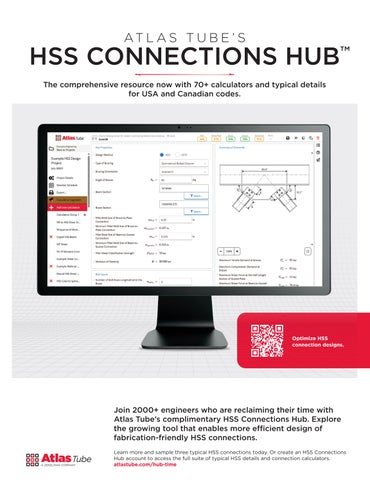
HSS CONNECTIONS HUB™ The comprehensive resource now with 70+ calculators and typical details for USA and Canadian codes.
Optimize HSS connection designs.
Join 2000+ engineers who are reclaiming their time with Atlas Tube’s complimentary HSS Connections Hub. Explore the growing tool that enables more efficient design of fabrication-friendly HSS connections. Learn more and sample three typical HSS connections today. Or create an HSS Connections Hub account to access the full suite of typical HSS details and connection calculators. atlastube.com/hub-time
RELENTLESS SUPPORT.
An ever-expanding resource for engineers, detailers and fabricators now featuring over 100 new updates. What’s New Highlights
Recently Released • Direct-input factored loads: Import factored reactions directly from your favorite analysis software. • Automatic truss type detection: We’ll identify the correct truss type (T, K, Y, X, etc.) for you. • Axial loads in moment connections: Apply axial loads to moment connections—shear connections coming soon! • Built-up tees in WT connections: Customize tee sizes for WT connections beyond handbook limits.
Launching in January • HSS columns and beams for brace calculations: Connect braces to HSS beams and columns, expanding beyond current WF options. • New truss connections: Enjoy support for X connections with round HSS and overlapped KT configurations. • Moment in End Plate splices: Moment loads are now supported in splice connections for greater versatility.
Available in February • Shear in splices: Apply and check shear loads on splice connections for enhanced safety. • Extended configuration for shear plates: Add more bolt lines and length to shear plates for increased adaptability. • Seismic design: Seismic design category determination and Ordinary moment frame (OMF) checks.
• Custom bolt spacing for splices: Optimize bolt spacing to maximize splice capacity.
Create an HSS Connections Hub account today! Access the full suite of typical HSS details and connection calculators. atlastube.com/hub-time
STRUCTURE JANUARY 2026
NCSEA | CASE | SEI
Structural Solutions For a University Hospital p. 24
INSIDE: Ohio State Univ. Inpatient Tower
24
Common Pitfalls in Diaphragm FEM 8 Renovating a Building for Modern Research 16 An Institute Among the Trees 20
POWERFUL STEEL AND CONCRETE DESIGN AT YOUR FINGERTIPS
Save time and money with the world-leading structural design software. Connection design at its best Steel anchorage workflow Supplement your strut and tie analysis Any geometry, any loading, in minutes Intergates with your software
www.ideastatica.com
Try the full version for 14 days for free
ADVERTISER index
Please support these advertisers
Atlas...................................................................................... Onsert Computers & Structures Inc...................................................... Back Cover CTS Cement....................................................................... 9 DEWALT.............................................................................. 10 ENERCALC......................................................................... 7 IDEA StatiCa...................................................................... Inside Front Cover Inducta................................................................................. 11 MAX USA CORP.............................................................. 14 SEI......................................................................................... 34 QBCorp............................................................................... 30-31
STRUCTURE
®
CIRCULATION
subscriptions@structuremag.org
EDITORIAL BOARD Chair John A. Dal Pino, S.E. Claremont Engineers Inc., Oakland, CA chair@STRUCTUREmag.org Kevin Adamson, PE Structural Focus, Gardena, CA Marshall Carman, PE, SE Schaefer, Cincinnati, Ohio Erin Conaway, PE AISC, Littleton, CO Sarah Evans, PE Walter P Moore, Houston, TX
January 2026 Digital Issue Available Only at
STRUCTUREmag.org
Publication of any article, image, or advertisement in STRUCTURE® magazine does not constitute endorsement by NCSEA, CASE, SEI, the Publisher, or the Editorial Board. Authors, contributors, and advertisers retain sole responsibility for the content of their submissions. STRUCTURE magazine is not a peer-reviewed publication. Readers are encouraged to do their due diligence through personal research on topics.
Steven Judd Interstate Brick, West Jordan, Utah, and H.C. Muddox, Sacramento, California Linda M. Kaplan, PE Pennoni, Pittsburgh, PA Jessica Mandrick, PE, SE, LEED AP Gilsanz Murray Steficek, LLP, New York, NY Brian W. Miller Cast Connex Corporation, Davis, CA Evans Mountzouris, PE Retired, Milford, CT Kenneth Ogorzalek, PE, SE KPFF Consulting Engineers, San Francisco, CA (WI) John “Buddy” Showalter, PE International Code Council, Washington, DC Eytan Solomon, PE, LEED AP Silman, New York, NY
EDITORIAL STAFF Executive Editor Alfred Spada aspada@ncsea.com
Managing Editor Shannon Wetzel swetzel@structuremag.org
MARKETING & ADVERTISING SALES Senior Director for Business Development & Marketing Monica Shripka Tel: 773-974-6561 monica.shripka@STRUCTUREmag.org
Sales Manager Audrey Schmook Tel: 312-649-4600 Ext. 213 aschmook@ncsea.com STRUCTURE magazine (ISSN 1536 4283) is published monthly by The ®
On the Cover: At 1.9 million square feet, The Ohio State University’s (OSU’s) new University Hospital in Columbus, Ohio, is the largest single project in the University’s 155-year history. This 22-level seamless connection to the adjacent James Cancer Hospital and Solove Research Institute is among the most intricate in the nation. Here, the construction of the jump-formed concrete core walls, ahead of the steel-framed floors, kept pace with an accelerated schedule.
National Council of Structural Engineers Associations (a nonprofit Association), 20 N. Wacker Drive, Suite 750, Chicago, IL 60606 312.649.4600. Periodical postage paid at Chicago, Il, and at additional mailing offices. STRUCTURE magazine, Volume 33, Number 1, © 2026 by The National Council of Structural Engineers Associations, all rights reserved. Subscription services, back issues and subscription information tel: 312-649-4600, or write to STRUCTURE magazine Circulation, 20 N. Wacker Drive, Suite 750, Chicago, IL 60606.The publication is distributed to members of The National Council of Structural Engineers Associations through a resolution to its bylaws, and to members of CASE and SEI paid by each organization as nominal price subscription for its members as a benefit of their membership. Yearly Subscription in USA $75; $40 For Students; Canada $90; $60 for Canadian Students; Foreign $135, $90 for foreign students. Editorial Office: Send editorial mail to: STRUCTURE magazine, Attn: Editorial, 20 N. Wacker Drive, Suite 750, Chicago, IL 60606. POSTMASTER: Send Address changes to STRUCTURE magazine, 20 N. Wacker Drive, Suite 750, Chicago, IL 60606. STRUCTURE is a registered trademark of the National Council of Structural Engineers Associations (NCSEA). Articles may not be reproduced in whole or in part without the written permission of the publisher.
JANUARY 2026
3
Contents JA N UA RY 2 0 26
Multi-Symptom Structural Solutions for The Ohio State University Inpatient Tower The structural design of a new university hospital addressed several challenges, including highrise-force winds, flood risk, vibration criteria, and an accelerated construction schedule.
24
F E A T U R E S RENOVATING EXISTING BUILDINGS FOR MODERN RESEARCH
16
By Timothy Schuster PE, SE
The renovation of a concrete research building involved a significant retrofit to relocate existing shafts and mechanical cores to optimize lab efficiency while maintaining building functionality throughout construction.
4
STRUCTUREmagazine
AN INSTITUTE AMONG THE TREES By Thomas Reynolds, PE, SE
20
Johns Hopkins University’s Stavros Niarchos Foundation Agora Institute maintains an interconnectivity among its three separate volumes through unique staircases, bridges, and a transparent facade.
C O L U M N S a n d D E PA RT M E N TS
6
Editorial
8
Ushering in a Year of Thriving on Challenges By John Dal Pino
8 Structural Design
Common Pitfalls in Diaphragm Finite Element Modeling By Swarna Karuppiah, PE
12
Structural Analysis
Contractor-Ready Construction Documents—Part 2 By Jeremy Salmon, PE, SE and Zak Pruitt, PE, SE
15
Structural Quality
12
Identification, Cause, Prevention, and Repair of Cracks By Dave Flax
32 Iconic Structures
Dynamic Loading Solutions in Taipei 101 By Jannat Ara Jabin, Krishna P. Ghimire, PhD., PE
32
37 Codes and Standards FAQ on SEI Standards By Jeannette Torrents, PE, SE
38 Historic Structures Winona High Bridge 1892 By Dr. Frank Griggs, Dist. M. ASCE
40
Structural Sustainability 10 Things Every Structural Engineer Should Know: Masonry By SE 2050 Resources Working Group
54
54 Book Review
A Singularly Unfeminine Profession—One Woman’s Journey in Physics By John Dal Pino
56 Structural Forum
Engineering Better Contracts By Mark Blankenship
In Every Issue 3 Advertiser Index 44 SE News 48 SEI Update 50 CASE in Point 52 NCSEA News
JANUARY 2026
5
EDITORIAL Ushering in a Year of Thriving on Challenges By John Dal Pino
L
et me be one of the first, who doesn’t know you personally, to wish you a Happy New Year on behalf of everyone at STRUCTURE magazine and the extended NCSEA family. If you haven’t noticed, we live in interesting times. I can clearly remember standing in my office a quarter century ago discussing with others the chances of our computers refusing to start up when we returned to the office in January 2000. No one prevailed in the debate because none of us knew anything about what we were predicting. I suppose we should have asked a computer expert? It turned out to be much ado about nothing. All of these years later, we are now having a similar debate about AI, with most of us knowing nothing about the details yet wondering when the computers will lock us out of the office, start performing calculations and preparing drawings, and generally make us humans redundant. Hopefully our new masters will be benevolent and give us enough money for food. But think of all the time off we will have! The end of work-life balance will be upon us. But thanks to AI, I now know that the Chinese New Year in 2026 will usher in the year of the Fire Horse and that there are five sub-types of the years of the Horse (although I didn’t ask), with the Fire Horse being one of them. The year of the Fire Horse will usher in energy, passion, and transformative potential, which are associated with traits like intelligence, courage, and independence. If you are expecting an addition to your family soon, babies born in in 2026 will be seen as energetic, confident, proactive, and thriving on challenges, with a strong desire for progress and breakthroughs. Sound like future structural engineers to me! If this sounds good and you are want to do the right thing by your new child, while also helping address the industry shortage of engineers, I figure you have about two months to get in the game. Enough fun and frivolity, or doom and gloom, as the case may be. Let’s get down to business and have a look ahead.
Call for Articles for STRUCTURE in 2026 The quality of this magazine is better than ever thanks to our authors, our editorial staff, and the dedicated editorial board volunteers. I hope you like the larger graphics as much as I do.
6 STRUCTURE magazine
STRUCTURE is the structural engineering profession’s primary vehicle for sharing information and educating structural engineers about topics they need to know about or topics they didn’t know they needed to know about (kind of like those messages from your AI app). We aim at the sweet spot, not too technical, not too light, and with enough information to inform and pique your interest to learn more. If you haven’t noticed, our major themes include concrete, steel, wood, and masonry (the big four on licensure exams), with sub-themes including wind, seismic, tall buildings, bridges, and computer software.
If you have an idea you would like to propose, or if you wish to update a previous article with new material, we would love to hear from you. I invite you to contribute by writing for STRUCTURE. While technical and projectrelated topics are our bread and butter, readers also enjoy articles that educate them on the full breadth of the engineering profession, including business issues. These under-explored topics include challenges facing small firms (meeting and developing clients, monitoring company and project finances, hiring staff, etc.), larger industry trends (the economics of construction, material selection and availability, labor, etc.) and research (new and evolving technologies, innovative or improved engineering tools, cutting-edge research, etc.). The magazine succeeds because of you. So please don’t be bashful. If you have an idea you would like to propose, or if you wish to update a previous article you authored with new material, we would love to hear from you.
Our Next Phase of SE GPT Our first year with a dedicated structural engineering GPT based largely on STRUCTURE magazine articles, along with other NCSEA and affiliated resources, has been a successful first step in using this technology. STRUCTURE is broadening
its AI capabilities with a new tool to be launched in the spring of 2026. Like the original SE GPT, this tool will answer queries based on a closed database that includes structural engineeringspecific resources. This means, STRUCTURE magazine articles, NCSEA publications, NCSEA webinar transcripts, white papers, and other documents. The update will be more user-friendly and better integrated into our website, so users won’t have to navigate to a third-party site. The tool itself also has additional capabilities that will help expand its knowledgebase. It will be a sort of “Super Librarian” for our readers.
The NCSEA Summit Travels to San Francisco The NCSEA Summit will be held for the first time in San Francisco in October. The organizers for the 2025 Summit in New York City were happy to announce that the event set an attendance record of over 1,000 individuals. Just 10 years ago, the NCSEA annual event drew 200. Hundreds of practicing structural engineers, industry leaders, and innovative thinkers gathered in New York City to explore the latest advancements in structural engineering. Speaking as a native San Franciscan, October is a great time to visit northern California. The late summer weather is pleasant (as usual), there is less coastal fog, and the last of the wine grapes are being harvested. Consider expanding your visit to an entire week and have a look around at what there is to see. We spoiled locals don’t explore as much as we ought to, but I guarantee that a drive north or south along the coast, a day trip to Monterey and Carmel or a quick visit to the Redwoods farther north, will be rewarding experiences. Please make 2026 a year for sharing your knowledge with others, exploring new tools and resources available to us, and coming to San Francisco to meet with your colleagues. ■ John A. Dal Pino is a Principal with Claremont Engineers, Inc. in Oakland, California. He serves as the Chair of the STRUCTURE Editorial Board (jdalpino@claremontengineers.com).
structural DESIGN
Common Pitfalls in Diaphragm Finite Element Modeling
While contours may appear intuitive, discerning real diaphragm force flow demands a more thoughtful approach. By Swarna Karuppiah, PE
F
inite Element Modeling (FEM) has become an essential tool for diaphragm design, offering engineers the ability to capture in-plane shear flow, visualize redistribution around openings, and quantify collector and chord demands hidden under rigid-diaphragm assumptions. However, finite element models are only as reliable as the assumptions behind them. Misaligned plate axes, coarse meshes, incorrect support definitions, or misinterpretation of results can lead to misleading outputs. More subtly, plate–member stiffness interaction can redistribute forces in ways that diverge from design intent, producing surprises during detailing. This article outlines common pitfalls in diaphragm FEM and provides practical recommendations to help engineers achieve reliable, code-compliant results.
Why This Matters Diaphragms are the load-distribution backbone of the lateral system, transferring wind and seismic forces to shear walls, braced frames, and moment frames. Most industry software allows engineers to model diaphragms as rigid, semi-rigid, or flexible: • Rigid diaphragms tie all nodes at a floor together for in-plane translation and rotation, distributing loads solely by connected element stiffness. It is ideal for flat, stiff concrete slabs where in-plane deformation is negligible. In FEM software, default stiffness is in the order of ~10⁷ times the modeled slab stiffness, adjustable for convergence or ghost-reaction issues. Ghost reactions occur when the model is so stiff or over-constrained that the solver diverts small numerical inconsistencies into support directions that cannot be justified by actual loading. They generally point to overly stiff links, distorted plates, or diaphragm assumptions that need correction. • Semi-rigid diaphragms distribute loads based on diaphragm stiffness and element stiffness, providing a realistic force flow. It is used for irregular plans. For in-plane action only, use element formulations that do not contribute out-of-plane bending stiffness. Compare rigid and semi-rigid results—if force distribution differs by more than ~10%, diaphragm flexibility likely matters and should be captured as semi-rigid. • Flexible diaphragms act as load-attribution devices with no stiffness in the matrix, distributing loads by tributary area. It is common for wood or light-gage deck systems where diaphragm deformations dominate.
Diaphragm Modeling With the importance of diaphragm behavior established, the next step is deciding how to model it using plate elements that capture the 8 STRUCTURE magazine
Fig. 1. A meshed diaphragm shows force discontinuity across misaligned corner nodes.
in-plane stiffness of the slab. By assigning a material that reflects the diaphragm’s actual properties—modulus of elasticity, thickness, and weight, the plate can capture the properties representing the real deck system, whether concrete, composite, or steel deck. Next, if the model fails to capture the conditions where a diaphragm steps vertically at features such as canopies, podium transfers, or mezzanines, the discontinuities can produce artificial stress concentrations and disconnected regions. Using FEM plates with offset links or vertical connection elements allows loads to transfer across these steps and helps trace collector forces through the discontinuity. Finally, turn to meshing. Even with proper materials and offsets, many FEM errors are subtle and only reveal themselves in the outputs. As shown in Figure 1, misaligned plate corners prevent the mesh from forming a continuous boundary between adjacent plates. The solver then treats the plates as disconnected, interrupting membrane force transfer and creating the abrupt contour change. Ensuring aligned nodes or consistent mesh divisions across plate edges restores proper force flow. A carefully constructed mesh is critical to ensuring that the results are accurate reflections of diaphragm behavior.
Plate Local Axis Orientation Plate local axis misalignment is one of the easiest problems to overlook, yet it can have a major impact on the clarity of the results. Each plate element has its own local axes, which define the directions of its in-plane membrane forces. When some plates are rotated relative to others, what should be a smooth force flow can appear jagged or discontinuous in contour plots, creating false “cracks” in the diaphragm. The orientation of local
Fig. 2. A combination of triangular and quadrilateral meshed plates connects each to vertical framing.
element axes can be visually confirmed early in the modeling by displaying the local axis arrows, helping ensure consistent alignment across plates. Though this does not affect the individual plate forces, the contour plots can mislead the actual flow.
Mesh Resolution
Shrinkage-Compensating Concrete & Grout Solutions
MEETS STRINGENT SUSTAINABLE DESIGN CRITERIA.
ADVANTAGES Eliminate Negative volume change Control joints Curling Maximize extended joint spacing
Improve structural performance Maintain dimensional stability Lower permeability Maximize long-term durability Enhance strength and abrasion resistance
ADVERTISEMENT–For Advertiser Information, visit STRUCTUREmag.org
A mesh that is too coarse will smear peak shear flows and underestimate collector or chord forces, while one that is unnecessarily fine can slow solution times and generate noisy contour plots that obscure global trends. Mesh resolution is one of the most influential factors in the accuracy of diaphragm FEM results. A best-practice approach is to treat mesh refinement as an iterative process. Start with a reasonably coarse mesh size of 10% of the diaphragm span, record critical results— such as peak Nx near openings, chord force at the diaphragm edge, or total base shear reactions—and progressively refine the mesh. Once further refinement produces only a small change (commonly <1–2%), the model can be considered mesh-independent for that quantity. A diaphragm often uses a combination of quadrilateral plates in uniform regions and triangular plates near irregular geometry, with plate nodes aligned along line features such as roof ridges, valleys, or diaphragm openings as shown in Figure 2. This mix avoids highly skewed quads while still keeping the mesh efficient, ensuring that nodes
Booth #S10405 JANUARY 20–22 Fig. 3. A rigid link connects stepped diaphragm to vertical framing.
CTScement.com 800.929.3030
JANUARY 2026
9
Plate–Member Interaction
Fig. 4: Diagram showing chord force contours; colors indicate relative magnitudes of in-plane forces in in kips/ft.
occur at line elements where membrane-only plates can transfer in-plane forces even though they have no out-of-plane moment stiffness. Plate elements shall maintain a reasonable length-to-width and thickness-to-width ratio to prevent distortion and ensure plate theory remains valid. Triangular elements should also follow these proportion guidelines—avoid sliver triangles with very short edges or extreme angles, which can produce inaccurate stiffness and stress results. Importantly, engineers do not need a uniformly fine mesh everywhere. Refinement should be concentrated near re-entrant corners, openings, and stiff boundaries, while less critical
regions may remain coarser to keep the model efficient. This targeted approach balances computational cost with engineering accuracy and is especially helpful for large building diaphragms. Most FEM solvers compute internal stresses at Gauss points and then extrapolate them to nodes. When adjacent elements report very different values at the same node, it indicates the mesh is too coarse in that region. As the mesh improves, these discontinuities shrink—making contour plots smoother and more physically meaningful. Many software packages even report a percentage discontinuity at shared nodes, which can be used to estimate solution error.
Perhaps the most misunderstood pitfall is unintended load sharing between plates and members. Because FEM distributes load by relative stiffness, beams or trusses may attract less demand than expected when stiff plates are present. For example, a beam expected to carry 15.5 k-ft of moment only carried 7.3 k-ft when a slab plate was included—a 47% reduction. In another, a truss top chord saw axial load reduced by ~40% when a metal deck plate was modeled. If plates are intended for diaphragm action only, use Plane Stress options to eliminate out-of-plane stiffness. Apply gravity loads directly to beams when appropriate. For orthotropic decks, model directional stiffness explicitly.
Missing Supports For a diaphragm to perform its role, it must connect to lateral force-resisting elements such as shear walls, braced frames, or moment frames. Yet in many finite element models, plate meshes are drawn without sharing nodes with these vertical elements. The result is a diaphragm that
ADVERTISEMENT–For Advertiser Information, visit STRUCTUREmag.org
BUILT FOR THE UNBREAKABLE
™
BEING RELENTLESS, ADAPTABLE, AND SAFE IS NOT A CHOICE— IT’S THE JOB.
SCAN TO LEARN MORE
STATE-OF-THE-ART STRUCTURAL DESIGN SOFTWARE DESIGN
Code-compliant anchor designs according to ACI 318-19, ACI 318-14, and CAS A23.3-14
DOCUMENT
Comprehensive design calculations with numerous reporting options
10 STRUCTURE magazine
COMPARE
Compare multiple anchor types, sizes, and brands at a glance to efficiently evaluate design requirements
ANCHOR
Strengthen your design with a full catalog of DEWALT® anchors
appears stiffer than reality, while the intended wall or frame “floats” without reactions. At the other extreme, some models restrain diaphragm motion with a single fixed node, creating unrealistic force concentrations. First, verify that plate edges share nodes with adjacent wall or frame elements so that diaphragm shear is delivered into the vertical system. Second, use rigid links or line constraints where needed to distribute stiffness along edges, particularly when a stepped diaphragm meets a vertical frame as shown in Figure 3. Finally, review support reactions against simple hand-calculated shear distribution to confirm that load paths are modeled as intended.
models are indispensable for today’s complex building geometries. But their sophistication demands discipline. Misaligned axes, poor meshing, misplaced supports, misread results, and unintended stiffness interactions can all undermine design if left unchecked. By approaching diaphragm FEM with intention—aligning, refining, filtering, and validating—engineers can turn pitfalls into insights. The reward is not just colorful contour plots, but trustworthy results that guide efficient detailing, clear coordination, and resilient buildings. ■
Full references are included in the online version of the article at STRUCTUREmag.org.
Swarna Karuppiah, PE, is a structural engineer at Datum Engineers at Austin, Texas, with experience designing across commercial, educational, and government buildings.
Interpreting Contour Plots
Introducing INDUCTA’s
Stress contours like Von Mises plots can be a useful diagnostic in FEM diaphragm modeling, but they are calculated from the in-plane principal stresses of the plate and plotted with a smoothing algorithm that interpolates values across nodes. Contours may not match the raw element values at specific locations, especially in regions of high stress gradients. They inform us of overall stress intensity, highlighting regions of concentration near openings, supports, or re-entrant corners, but what they don’t show is the diaphragm shear demand directly. For diaphragm design, rely on membrane force plots and strip-averaged extractions. Chord forces are obtained by integrating the in-plane membrane forces along a selected span of the diaphragm, as illustrated in Figure 4. The resulting axial couple at the diaphragm edges is the chord force: one edge in tension, the other in compression. This strip-averaging method filters out local “hot spots” where a spike near an opening may be reduced through a strip integration producing 40% to 50% lesser demand. The overall design strips can be compared against hand checks to benchmark FEM reactions against code-based diaphragm force distribution. Used properly, Von Mises plots can complement force-based design checks by flagging areas of unusual stress concentration, but they should not replace membrane-force extractions or hand-calculated checks.
Automated RC Column Design & Schedule
If the diaphragm forces appear unwilling to agree, the cause is often a subtle lapse in mesh communication. Finite element diaphragm
Level
C47
C48
C49
C50
C51
C52
C53
C54
C55
C57
C58
Story8 f'c: 6000 psi H : 10.66 ft
3,200 Story7 f'c: 6000 psi H : 10.66 ft
3,100 3,000 2,900 2,800 2,700 2,600 2,500 2,400
ADVERTISEMENT–For Advertiser Information, visit STRUCTUREmag.org
Conclusion
Design and Detail RC Columns in Record Time
Story6 f'c: 6000 psi H : 10.66 ft
2,300 2,200 2,100
Axial Load - ΦΡ (kip)
2,000
Max Comp 1,900 (0, 1852) 1,800 1,700
Allowable Comp. (282, 1482)
1,600 1,500
Story5 f'c: 6000 psi H : 10.66 ft
fs = 0 (396, 1284)
1,400 1,300
Mn, Pn (808, 1258)
Mpr, Pu.max (864, 1252)
1,200 1,100
Mpr.max, Pu (893, 1042)
fs = 0.5fy (509, 921)
1,000 900 800
Mu, Pu
700
ΦMn, ΦPn (514, 889)
(452, 800)
600
Story4 f'c: 6000 psi H : 12.66 ft
fs = εy + 0.003 (580, 454)
500
Mpr, Pu.min (726, 432)
400 300 200
Pure Bending (332, 0)
100 0
0
50
100
150
200
250
300
350
400
Story3
450
500
550
Moment - ΦMx-Top-Ult (kip-ft)
f'c: 8000 psi 600 650 H : 12.66 ft
700
750
800
850
900
950
Accelerate your RC column design to ACI 318 and CSA A23.3. Design and detail for strength, fire resistance, restraint, core confinement, shear, and seismic requirements with the click of a button. Streamline your workflows by importing data directly from CSi and/or Bentley software. Refine the design using column groups, with effortless export options to Excel, .dxf, or Revit. The entire column schedule can be designed, rationalized, and detailed all within one integrated software solution.
For a free trial contact info@inducta.com.au
inducta.com.au JANUARY 2026
11
C
structural DESIGN Contractor-Ready Construction Documents—Part 2
Contractor involvement can optimize the design, detailing, constructability, and sequencing on a building project. By Jeremy Salmon, PE, SE and Zak Pruitt, PE, SE
D
esign decisions are typically based on previous experience, engineering judgment, and code requirements. However, the project location, general contractor, trade partners, and local practices may impact the structural design and detailing. Contractor involvement during design can provide input on key decisions in the selection of structural systems, use of building materials, and more. Instead of value engineering after the project has been completed, contractor assistance can avoid costly redesign efforts and schedule delays. Part 1 of this series, which appeared in the December 2025 issue of STRUCTURE, discussed contractor input that affects the design of the structure. Part 2 discusses contractor input that affects detailing, constructability issues, and construction sequencing.
Rooftop Units During design, mechanical engineers use preferred vendors to size mechanical units with their associated weights and dimensions. This information is used to size and locate beams to support the heavy load of the mechanical unit and frame around the required duct openings. Sometimes, these units are altered during the contractor’s bidding process and the weights and/or dimensions are changed. This results in potentially reframing and re-designing a portion of the structure to accommodate the final selected unit. This effort can have schedule, cost, and re-detailing implications.
Elevator Early Release Package Elevators are frequently put out to bid after construction documents are issued. The hoistway size, pit depth, overrun requirements, rail forces, etc. always vary between manufacturers. The surrounding structure, such as slab edges, beam locations, and mat foundations, are all affected. Projects with concrete shearwalls frequently rely on elevator shaft concrete walls to help provide the lateral load resisting system for the structure. A change in hoistway dimensions will alter the shearwalls. Recruiting contractor assistance in producing an early-release elevator package or at least selecting the elevator supplier during design can reduce the amount of redesign and re-detailing required after construction documents are issued.
Foundation Excavations Contractor input on how to handle different foundation types in varying subsurface conditions can simplify construction and save time in the project schedule. • Projects requiring controlled blasting or excavation through rock may have several options for foundations. The contractor may 12 STRUCTURE magazine
•
•
prefer to over-excavate rock to a constant bearing elevation so the bottom of every footing is the same. The footing thickness could be the same for each footing size, or the top of each footing could vary. Alternatively, lean concrete can be considered to provide a means for shallower footings to also bear on the same rock while maintaining a constant top of footing and constant bearing strata. The preferred approach will potentially impact the column and wall heights. Auger cast pile foundations will have pile caps with varying number of piles. For each pile cap, the thickness can be optimized depending on the number and layout of the piles. Instead of varying the pile cap thickness, the contractor may prefer to make all pile caps the same thickness. This provides the drill rig a flat surface on which to maneuver during pile installation. Sites with highly variable rock elevations may involve a combination of both spread footings and drilled piers. For example, a 50-foot elevation difference in rock elevation has been observed across many project building footprints. Once the column layout is set, mobilizing the contractor to make additional borings at each column location can provide valuable information before construction starts by identifying where rock is anticipated at each column location.
Prefabricated Exterior Wall Panels Prefabricated exterior wall panels provide the benefit of assembly in a shop environment and speed of erection on site. Early selection of the prefab wall supplier by the contractor provides valuable input to the design team. • For projects with large floor heights and high wind speeds, the supplier can determine the wall stud depth that will be required, so the exterior wall profile is depicted correctly. • The slab edge and bent plate dimensions will be set by how much tolerance and air space is required by the selected prefab wall supplier. This can potentially impact column locations and beam/columns sizes. Steel members with large flange widths and fireproofing can potentially conflict with the wall panels (Fig. 1) • The prefab wall supplier can help define which portions of the building elevations may not prove to be efficient with prefab wall panels and when stick-framed stud walls are more appropriate. For instance, a short stud knee wall under a strip window may be more effective with stiffening channels in the stud walls compared with stud moment resisting connections at the wall base track. • Maximum panel heights and widths and joint locations can be reviewed with the prefab wall supplier, which will need to be incorporated into the building elevations and beam designs.
Earth Retention System Where temporary or permanent earth retention systems will be required, contractor involvement, along with their preferred specialty foundation contractor, benefits the design team by providing feasible options for the project. Determining how close a new building with a basement can be located to an existing structure may be driven by the earth retention system that is used.
Early-release Sleeve Package Locating openings in floor slabs is critical to ensure the integrity of the structure. Prefabricated bathroom pods often used in healthcare facilities have specific opening locations with minimal tolerance for field adjustments. Early involvement by the contractor and prefab supplier will allow sleeve locations to be identified prior to construction. Not having this information prior to construction may require retrofit or additional supporting structure to accommodate field cut openings. Coring through a two-way concrete system will be problematic if there is no flexibility with core locations. Existing slab reinforcement is often cut during coring, which reduces significantly the shear/flexural capacity of the slab.
City Review Process Some cities and counties require structural calculations to be submitted for review prior to issuing a permit for construction. The review process may be done by the city itself, or may be outsourced to another engineering firm. The city comments may lead to changes to portions of the design and detailing of the structure, which in turn affects shop drawing production, fabrication, and the start of construction. Additional time is typically required to allow for correspondence with the City to resolve any review comments and generate any additional calculations the City may require. Discussions with the contractor during design
Fig. 1. Exterior wall slab edge conditions are detailed.
Fig. 2. Column relocation is shown. JANUARY 2026
13
about the City review process can assist in the development of the project schedule and owner expectations.
Verify As-built Conditions Expanding existing buildings always requires field verification. A set of existing design drawings is not the same as having an accurate set of as-built drawings or field survey information. At the time of the existing building construction, field modifications, RFI (Requests For Information) responses, changes made to shop drawings, etc. are often not depicted on the existing drawings. Having a contractor on site during the design phase to investigate the existing building will save potential delays once construction begins. As-built conditions can affect the design in countless ways, such as the following: • A survey locating the size, location, and orientation of the existing building relative to the new addition is essential. • As-built column orientation and detailing do not always match the existing drawings which will affect new beam lengths that are supported by existing columns. • Grid-tag dimensions will not match the theoretical grid-tag dimensions due to tolerances. • Modifications may have been made to the existing structure during a previous renovation for which there were either no drawings prepared or they are lost over time. For example, a new rooftop unit may have been added along with additional steel support beams; or, an existing column may have been relocated to provide additional square footage in a particular room (Fig. 2).
Phasing Considerations Renovating or expanding existing structures frequently involves phasing to minimize the downtime of portions of the facility. Temporary exit paths and careful phasing is an important part of the project for the owner. Understanding the phasing plan may impact the design by requiring additional foundation walls to provide temporary egress stairs early during construction. Or, if beam or joist retrofits are required, the extent of work in a particular phase may need to be increased to capture the space needed for the fix.
Conclusion Contractor involvement during design can help take the guesswork out of what may be preferred and considered most economical by the contractor in addition to identifying/confirming existing site and building conditions. The design, detailing, constructability, and sequencing can be optimized to provide a cost-effective project and minimize potential design and drawing changes after construction documents are issued. ■
Jeremy Salmon, PE, SE, is a principal at Structural Design Group in Nashville, Tennessee. He may be reached at Jeremys@sdg-structure.com. Zak Pruitt, PE, SE, is an associate principal at Structural Design Group and may be reached at zakp@sdg-structure.com
ADVERTISEMENT–For Advertiser Information, visit STRUCTUREmag.org
HN120
THE BEST WAY TO INSTALL METAL TRACK! Works With The AKHL1320E Powerlite® High Pressure Compressor
SCAN HERE TO SCHEDULE A PRODUCT DEMONSTRATION
14 STRUCTURE magazine
Central Hall: #C4005 Silver Lot :#031137
All MAX products are protected by registered patents and design rights including trademarks. For details, please contact MAX.
structural QUALITY Identification, Cause, Prevention, and Repair of Cracks By Dave Flax
C
racks aren’t all the same. Many different types of cracks happen for many different reasons. They can be due to construction defects, job-site conditions, design problems, contractor error, environmental issues, change of use, concrete issues, shrinkage, etc. Many cracks do not have a single cause but rather a combination of causes. For example, Figure 1 shows a plan view of a doorway in a wall of a warehouse in the first of many identical warehouses on a project in Mesa, Arizona. Look at the cracks and take a moment to think about (1) the cause of the cracks and (2) how to prevent similar cracking on future projects. This warehouse had many dozens of overhead doors, and almost all the doorways had a similar cracking pattern. Many readers might see the re-entrant corner as the cause. Others are certainly screaming drying shrinkage. Some are probably thinking that because this is in Arizona the hot, dry, windy conditions were the problem. All are contributing factors, but none of them were the primary cause of those cracks. Restraint was the main culprit. The stem wall foundation was placed, the CMU walls were built above, the foam expansion joint material was put into place, and the slab was cast. As the figure shows, the slab in the doorway was placed directly on top of the stem wall, which had a very rough top surface. That rough top surface was great for where the CMU walls were placed, but it locked the slab to the stem wall in the doorway. When shrinkage occurred, the concrete slab was free to move except at the doorway where it was restrained by the stem so the concrete cracked as shown. That is why everything concerning each crack isn’t just important. Everything is essential. In this example, an investigator would need to know about the construction sequence in addition to reviewing the drawings to develop a step-by-step sequence of events that would lead to the cause. The solution to prevent similar cracking on the remaining warehouses
Fig. 2. Twenty-three types of cracks (illustrated here in red) will be covered in a webinar on February 19.
Fig. 1. Cracks appeared near the doorway in a wall of a warehouse. What caused the cracks, and how can they be prevented in future projects?
was to finish the top of the stem walls smooth at the doorways. Then, just to make absolutely sure that restraint would not be a problem, two strips of bond breaking, poly sheeting were placed on top of the stem walls at the doorways. Voila. Similar cracking did not occur in the other warehouses. An NCSEA webinar will cover this topic on February 19. The presentation will go over 23 different types of cracks with photos and time for questions (Fig. 2). The following items will be discussed for each type of crack: • How to identify it. Knowing what type of crack you are dealing with is always the first step. • What caused it. It is extremely important to know the cause of the cracking before repairs begin. The webinar will cover how to determine the cause. This is essential because any repair must address the cause, not just the symptom. • How to prevent it. If we know how to prevent the cracking, we can make the changes necessary to reduce or eliminate similar cracking on future projects. • How to repair it. The methods used for structural, functional, and aesthetic crack repairs will be covered. A myriad of repair materials and methods are available in the marketplace, and the selection of the correct materials and the correct application methods will be discussed. Visit www.ncsea.com/webinars to register for the webinar. ■ Dave Flax, engineer, is the South-Western Regional Manager with the Business Development Group of the Euclid Chemical Company.
JANUARY 2026
15
Photo courtesy of HDR © 2023 James Lane Steel jackets around concrete columns allowed for flexibility in the framing to account for existing conditions and MEP coordination.
Renovating Existing Buildings for Modern Research The renovation of a concrete research building involved a significant retrofit to relocate existing shafts and mechanical cores to optimize lab efficiency while maintaining building functionality throughout construction. By Timothy Schuster, PE
O
ne of America’s leading research centers has dramatically reshaped its existing campuses through a combination of major new construction, renovation, and expansion. Part of this transformation included the modernization of the existing 23-story research building known as the “Avenue.” Originally constructed in the 1990s, the Avenue building contains public spaces, laboratories, and staff residences. The renovations of the Avenue included 120,000 square feet of existing space on the second through sixth floors of a 23-story building to create modern, flexible labs that support critical research. In order to achieve a modern and efficient lab space, existing shafts and mechanical cores had to be relocated, which created some structural challenges and the need for innovative design solutions.
16 STRUCTURE magazine
Existing Structure and the Challenges: Why Steel The Avenue building superstructure consists of one-way and twoway reinforced concrete flat slabs. The existing floor plans located the main mechanical shafts within the middle of the structural bays of the building with plumbing risers located on a select number of columns. The existing slab design only included drop caps at columns with the plumbing risers to account for the reduction in the punching shear capacity. While the current layout of shafts and risers may have been ideal for research 25 years ago, this layout limited the design team’s ability to optimize and modernize the space for current research consistent with other buildings on campus. For example, the
Photo courtesy of HDR © 2023 James Lane
Photo courtesy of HDR © 2023 James Lane
Avenue building did not have the same flexibility as new steel construction in terms of layout of columns and mechanical openings to fit within lab spaces. The solution was to infill the existing shafts and risers with reinforced concrete and relocate the shaft openings to areas that maximize the layout of modern labs. This required penetrating the existing slab with large new mechanical shafts and adding plumbing risers adjacent to columns, greatly reducing the punching shear capacity of the slab and column joint. Dealing with any existing structure comes with unique challenges and requires careful coordination between all design team disciplines taking into consideration the current conditions and limitations. During the modernization of the Avenue, consideration of occupants above and below the stories under renovation needed to be considered. This meant limiting the hours of noisy work such Steel framing was modified to existing utilities that were critical to building operations. as drilling and jack hammering. Another challenge was that operations and utilities that pass through the building to other parts of the building complex needed with creating openings in a two-way concrete slab. This made it easier to be operable throughout construction, which meant phasing of to identify locations where the slab was overstressed and required mechanical, electrical, and plumbing (MEP) demolition and installa- strengthening. It also allowed the team to verify that the existing tion. Some ducts and pipes had to remain in place and the structural conditions were still valid for the current building code loading. modifications needed to be coordinated around them. As the building Based off the analysis, it was determined that if the new mechanical had undergone several prior minor modifications, as-built MEP draw- shafts were created without additional reinforcing, the existing slab ings were not available and as such many of these obstacles could not would be overstressed, and certain areas would see large deflections. have been known during the project’s initial design phase. Given the The design team reviewed several different building materials to existing conditions and constraints, the design team reviewed multiple reinforce the existing slab which included reinforced concrete, steel building materials and methods, with the goal of providing a solution plating, FRP, and steel framing. Utilizing fiber-reinforced polymer that would allow for flexibility based on the actual in-situ conditions. (FRP) to strengthen most of the slab was one option the team reviewed, as it provided a lightweight and non-intrusive solution that wouldn’t impact above-ceiling space MEP. After a careful review of the analysis Solution models, in many instances the size and number of openings created a large change in moment demands that went over the FRP’s capacity The first step the design team took was to create two different finite to increase the slab strength for flexure and punching shear. element models using CSI SAFE. The first one was to recreate the Another option the design team considered was the use of additional existing structure with all the current openings and penetrations, and concrete and reinforcing to improve the concrete superstructure’s loadthe second model included the existing structure modified with the carrying capabilities. Strengthening of existing slabs would require new updated mechanical openings. This approach allowed the team to slab and beam sections to be poured and bonded to the existing. This set a baseline model for tracking the redistributed forces that come would increase flexural capacity but would also require very close coordination between the existing rebar to remain and the large amount of rebar being drilled and epoxied into the existing sections. Additional challenges with this approach included the selective demolition of existing rebar, working around many existing plumbing utilities that had to remain operational, and working around existing electrical conduits in the slab that were to remain. With so many unknowns, there was the risk of major design changes during construction. In addition, the large number of reinforcing bars that would require drilling and epoxying into existing concrete would create much noise, impacting occupants above and below, and forcing the contractor to work during off-hours. For similar reasons to the concrete approach, the design team elected not to pursue reinforcing the slabs with steel plates and post-installed concrete anchors. While exploring the steel plating and FRP approaches, another option presented itself. To reduce the amount of drilling and provide maximum flexibility for the MEP team, the structural team explored using steel beams to frame out the openings. In this approach, the A mix of steel framing and FRP were utilized to strength the existing concrete slab.
JANUARY 2026
17
steel beams would support the concrete slab around openings and bring the loads directly back to the columns. This approach reduced the demand on the slabs, also reducing the amount of FRP required. FRP was still used in isolated locations away from the new openings to meet the slab strength design for the newly distributed forces where steel beams were not nearby. To reduce drilling for anchors and help with the construction schedule, the steel beams were designed for the full unbraced length for lateral torsional buckling. Steel jackets were installed around columns to transfer the beam forces into the columns safely without the anchors breaking out and having to rely on the column reinforcement for
concrete breakout. The face of the jacket that the steel beam framed into utilized anchor rods with an adhesive that were sized to transfer the beam reaction into the steel jacket and column; while through bolts with adhesive were used on the opposite column face to help with confinement and provide reinforcement for the concrete breakout. All oversized holes drilled into the concrete columns were infilled with epoxy or grout to minimize reduction to the column’s axial capacity. The column sizes at the lower levels of the 23-story high rise measured 2 feet by 3 feet, which made it difficult to drill holes for through bolts. Holes of this length have the possibility of not aligning and would need to miss rebar on all faces of the concrete columns. The steel
Steel drop cap with coordinated core locations to miss existing rebar.
Photo courtesy of HDR © 2023 James Lane
Due to existing conditions and MEP coordination modeling beams had to be skewed, but the steel jacks and anchors allowed for this flexibility.
Steel drop caps had to be coordinated with large duct work and other MEP.
18 STRUCTURE magazine
Photo courtesy of HDR © 2023 James Lane Photo courtesy of HDR © 2023 James Lane
contractor’s solution was to scan the columns and drill the holes on all four column faces, then survey the hole locations and create a custom-plated jacket for each column location. This ensured that each steel jacket fit in the field and had minimal adjustments. The use of steel beams was found to be very useful as the contractor started to demolish the existing labs spaces. Demolition activities uncovered previously unknown plumbing mains that served the whole building and could not be interrupted or shut off. Steel framing was quickly redesigned and resized as the demolition progressed, allowing the contractor to stay on schedule. The use of steel jackets also limited the need to redesign for field conditions since the jackets are very flexible in their ability to support any steel framing members. Steel beams were able to be offset and skewed to avoid existing mechanical ducts and pipes. In addition to the new mechanical shafts, Typical steel jacket and drop cap at existing concrete column. the plumbing risers were relocated to different columns than original. Since several columns were already steel jacketed, steel drop caps with stiffener plates were used to reinforce the beam-column joints for punching shear. The addition of the drop cap not only helped with punching shear capacity but also reduced the negative and positive bending in the slab since the slab design spans were shorter. The use of steel framing and steel drop caps reduced the demand on the slab’s top reinforcing at the column locations, which reduced the amount of FRP strips and did allow for a few existing rebar to be cut when locating the new plumbing cores. To maintain the existing slab’s negative bending capacity, all concrete slabs needed to be scanned and marked out so the plumbing contractor could locate their cores to avoid the existing rebar. The steel contractor utilized plexiglass templates that traced the plumbing cores to accurately fabricate the steel drop caps. A laser cutting machine produced very accurate steel members, saving significant time and labor to install the new plumbing risers. In addition to modernizing the main lab spaces, the central knuckle which provides circulation between adjacent buildings was to be renovated and included a redesign of the monumental stairs between floors. To provide a sense of openness, the design of the new steel stair did not include any supports at the mid-level landing, instead cantilevering out around the stair plinth. This allowed the architects to maximize circulation and use of space and provided optimal views of the two- A mix of threaded rods and through bolts with epoxy were used to support the new steel to concrete connections. story art wall. Support of the new stair required the existing floor opening to be modified, including infill and cutting of the existing concrete slab. Steel design team’s ability to perform major structural modifications to an beams were added around the opening that connect back to existing existing concrete structure by utilizing steel framing and FRP while columns and beams. The C10x30 stair stingers were supported by a maintaining building functionality and minimizing impacts to users steel HSS16x12x3/8 header that connected to two existing concrete during construction. The use of structural steel framing allowed for beams, originally not designed for such forces. To minimize impact flexibility for unknown field conditions and created an elegant soluand cost, the existing concrete beams were reinforced with FRP for tion to a very challenging project. ■ both flexure and shear.
Conclusion Upgrading any existing building requires careful consideration and analysis and outside-the-box solutions. The Avenue building modernization makes no exception, and the project showcases the
Timothy Schuster PE, is a structural engineer at HDR in the Princeton, New Jersey, office. (Timothy.Schuster@hdrinc.com)
JANUARY 2026
19
Surrounding trees are reflected in the exterior facade of the Stavros Niarchos Foundation Agora Building on the John Hopkins University Campus.
An Institute Among the Trees Johns Hopkins University’s Stavros Niarchos Foundation Agora Institute maintains an interconnectivity among its three separate volumes through unique staircases, bridges, and a transparent facade. By Thomas Reynolds, PE, SE
20 STRUCTURE magazine
The campus building is made up of three volumes: the main building, auditorium, and a center staircase referred to as the "spider."
T
Project Team he Stavros Niarchos Foundation Agora Building was designed to create a communal space on the JHU campus. It is made up of three separate volumes, about • Owner: John Hopkins University 57,000 total square feet, comprised of classrooms, office • Architect: Renzo Piano Building Workshop with Ayers Saint Gross and a large community space for exhibitions, conferences, or other • Structural Engineer: TYLin events. The three volumes maintain interconnectivity to each other • Construction Manager: Consigli and the surrounding campus at large through unique staircases, • Precast Concrete Fabricator: BPDL bridges, and a transparent facade designed to make the two end • Precast Concrete Design Assist Engineer: HGS volumes look like floating cubes surrounded by a dense landscape. The design team studied a number of different materials to achieve the desired aesthetic and feel, ultimately landing on structural steel 2018 Maryland Building performance standards. Other standard addiand load bearing precast concrete. tional design codes such as ASCE 7-16, (Minimum Design Loads for When working on a long-term project, you see the design evolve Buildings and Other Structures), ACI 318-14 (Building Code Requirements from its most original thoughts and aspirations to what is eventually for Structural Concrete and Commentary), and the American Institute of achieved in the field. Engineers don’t often take the time to appreciate Steel Construction 341-16 (AISC) Design Guides were referenced for how the first pass 2-D framing sketch grows into a well-coordinated, on loading requirements and material specific requirements. budget, goal-meeting new building. The Stavros Niarchos Foundation The building structure at and below grade is all cast-in-place concrete (SNF) Agora Institute (SNFAI) was no different; the first sketch supported by over 120 90-ton axial capacity auger pressure grouted looked like the 2-D stick model in Figure 1 and then grew through piles. The 12-inch thick cast-in-place concrete slab at the ground level multiple iterations into the institute that will serve the students at supports an exterior public plaza and landscaping. John Hopkins University for years to come. SNF Agora Institute is composed of two separate volumes—the main building and auditorium—interconnected by bridges and a center Challenges multi-level stair affectionately known as the “spider.” The main building has four stories A multitude of factors contributed to the with a roof, and the auditorium building has challenges faced when framing SNF Agora two stories with a roof and an interior mezzafor support of the main gravity and live loads: nine. The spider provides the pathway between What material could be expressed best to the two buildings with a continuous staircase match the owners and architects’ design connecting all floors as well as interior bridges aspirations? What framing layout provided providing access to the two buildings from the best path for MEP routing? How is that the second and third floors with additional achieved across two separate volumes and exterior egress stairs on either side of the main make it buildable? building and the auditorium building. Early iterations of the auditorium used Fig. 1. An early 2D model of the auditorium building is The design of the buildings followed the 2018 much different than the final design of the Stavros Niarchos steel framing with a story truss and tension International Building Code (IBC) with the Foundation Agora Institute building. tie rods (to stop the building from tipping JANUARY 2026
21
over) with two pairs of columns 7 feet apart braced frames, and precast concrete shear on either end, as it was intended to look walls. The inter-connected buildings needed like a floating glass cube. The trusses got to be designed to move independently but still bulky, and the building movement became provide public access across seismic joints. too much for the facade performance and Figure 3 shows how the movement joints were vibration requirements for user comfort. The laid out in each direction, at the structural main building tested a wood framed buildinterface of each building. The joint moveing within a steel frame with the rendering ment, subsequent joint size and lateral system shown in Figure 2. layout were each precisely coordinated so they This iteration used steel trusses, mass fit within the architecture at the seismic joint timber, and a thin steel-framed facade suplocation—allowing the necessary physical port around the perimeter. When this didn’t building movement without compromising work out because of the heavy steel and wood, architectural intent. the designers tried a cast-in-place concrete Fig. 2. An early 3D model of the main building looks Per the diagram shown in Figure 3, the option (standard reinforced, post-tensioned nothing like the final product. auditorium was seismically separated from and void formed were all put on the table). the spider and the main building while proHowever, this all proved costly given the need viding the lateral resistance for the exterior to support the building on piles, which drove up foundation costs precast concrete stair (which was directly attached to the slabs at and seismic loads. each level). A response modification factor of three (not specifically The final product for the gravity framing was an amalgamation detailed for seismic resistance) was utilized for seismic design with of all the different structural options studied. Both buildings are 120 mph, 3-second gust for MWFRS loads. Tension only, doublesteel-framed with concrete on metal deck, which was chosen for its steel plate braced frames (moment frames were too flexible and the flexibility, comparative (to concrete) lightweight, buildability, and exposed connections at the ground floor didn’t fit the architectural ability to provide framing for cantilevers and limited number of intent) are provided in three discreet locations at the ground floor columns while still meeting vibration criteria and other serviceability and four more locations between the second floor and the roof. requirements related to acoustic performance and deflection. The The braced frame connections and attachment points were caretypical slabs are framed with 3 ¼ inches of lightweight concrete on a fully coordinated with the architect, as they are exposed, with each 2-inch 18-gage metal deck spanning 10 feet between floor beams. The weld and connection designed with custom shaped gusset plates standard floor beams in the main building are 30 feet long W14x26s and steel forks and pins. The noted braced frames met the design with thirty 3/4-inch diameter headed shear studs with a ¾ -inch camber wind drift criteria (H/400) and the necessary seismic drift required to meet deflection criteria and allow space for MEP runs below them. to establish the seismic joint. W30 members serve as 66-feet span girders at the auditorium’s 2nd Moment frames are provided throughout the main building and floor and roof to provide column-free spaces below. The W30 roof provide the bulk of the lateral resistance. However, the flexible girders support a green roof and all the necessary lighting and equip- moment frame system was not enough to meet the wind and seisment support for the performance space below. mic drift needed to create the desired maximum seismic joint at the The lateral framing for the buildings is a hybrid of moment frames, interface with the spider. The interior precast concrete shear walls in the main building at the stair vestibules (originally assumed to be decorative “interior facade”) were redesigned to provide lateral resistance as shear walls. TYLin provided shear loads and overturning moments to the design assist contractor for the reinforcing design, and they worked together to design the connections to the superstructure such that the lateral performance needed for drift and strength (and seismic joint size) was provided by the combined lateral system.
The Spider
Fig. 3. This hand sketch of multiple buildings is similar to the final product.
22 STRUCTURE magazine
The spider structure is a focal point of SNF Agora Institute. It is not just the center, physically, of the buildings, but also the main artery through which users will traverse the structures and experience the space. Precast concrete was chosen as the main framing for the superstructure. TYLin worked with the design assist engineer to frame the spider. Each level of precast exterior ring beams and facade glass are hung from the precast/
pretensioned roof structure with exterior steel tension rods that deliver loads back to two columns and interior shear walls. The slabs that support the stairs and landings span between shear walls and the noted columns. The shear walls provide lateral resistance in the north-south direction, while the main building provides the lateral resistance in the east-west direction. The spider is tied to the main building in the east-west direction at their interface through short pieces of precast concrete bridge that provide the connection between the buildings and a lateral load path between structures. The noted bridge pieces needed to slip in the north-south direction but still transfer load in the east-west direction. The bridges that span from the main staircase in the spider to the auditorium are connected with a vertical seated connection that provides seismic slip resistance in the eastwest and north-south directions (Figure 4), creating an independent lateral system from the Auditorium building while still transferring vertical loads through bearing. These connections were carefully coordinated with the architectural team so they could slip in each direction, support load vertically and fit within the architectural enclosure without being seen. In addition, the connections had to be coordinated with the design assist contractor and engineer such that they understood the design intent.
Fig. 4. Shown is a seismic joint detail that provides seismic slip resistance in the east-west and north-south directions.
Conclusion SNF Agora is intended to provide students on the JHU Homewood campus with a place for conferences, speaker presentations, art exhibitions, labs and classrooms. The design team had the opportunity to study multiple different iterations of structure (both gravity and lateral) and material layout to meet architectural intent. The final product of steel framing, cast in place, and precast concrete served to provide open sight lines, column-free spaces, and an abundance of natural light. ■
Thomas Reynolds, SE, PE, is a structural engineer with TYLin in New York City. His experience encompasses a range of building types including healthcare, higher education, primary and secondary education, institutional and residential.
JANUARY 2026
23
Credit: Courtesy of Walsh/Turner Joint Venture Fig. 1. The new University Hospital tower is the largest single project in OSU’s history, at 1.9 million square feet and 26 stories high.
Multi-Symptom Structural Solutions for The Ohio State University Inpatient Tower 24 STRUCTURE magazine
The structural design of the new University Hospital addressed several challenges, including highrise-force winds, flood risk, vibration criteria, and an accelerated construction schedule. By James P. Mahoney, PE, SE, and Mike C. Jewsbury, PE, SE
A
Credit: Courtesy of Walsh/Turner Joint Venture
t 1.9 million square feet, The Ohio State University’s (OSU’s) new University Hospital in Columbus, Ohio, is the largest single project in the University’s 155-year history. Its 19-level seamless connection to the adjacent James Cancer Hospital and Solove Research Institute is among the most intricate in the nation. The project targeted several structural goals: control wind-related movement for occupant comfort, keep below-grade areas dry, meet strict vibration limits for imaging and operating rooms, and connect to existing hospital buildings without interrupting operations. Instead of concentrating on each challenge separately, the team developed integrated structural solutions that addressed multiple needs at once to achieve these goals. In prac2. The construction of the jump-formed concrete core walls, ahead of the steel-framed floors, kept pace with an tice, this meant using a coordinated structural Fig. accelerated schedule. strategy to manage wind and flood risks, support vertical circulation, allow for future flexibility, and reduce cost and schedule impacts. conflicts underground. On top of that, groundwater and flood risk required their own mitigation strategy. If “foundation layout” and “flood protection” were treated as separate probThe Case for an Integrated Approach lems, the result would be discordant layered solutions, adding complexity, cost, and risk of interference below grade. Rising 410 feet above the banks of the Olentangy River, the OSU • Given the building’s height, with inpatient comfort requireWexner Medical Center’s new University Hospital ranks among the ments, code checks alone would only confirm minimum drift 10 tallest buildings in Columbus. performance, not how the building feels to patients on the upper From the start, the design team favored an integrated approach floors. Wind-driven movement and acceleration needed tarto achieve a “stacked benefit” result for decisions, coordinating the geted control. If wind comfort were handled as an afterthought foundations, the structural lateral system, and the building’s main (for example, by adding stiffening measures late in design), the vertical elements (such as elevators and stairs) to solve several chalbuilding could risk coordination conflicts, added cost, and lenges at once. design inefficiencies instead of factoring comfort into the main • A field of many small-diameter deep foundations may seem structural system from the beginning. simple, but on this site, it meant hundreds of extra below-grade • The critical circulation path from helipad and Emergency intersections, longer installation time, and more chances to hit Department to ORs and interventional suites has strict requirements: fast, direct, and unobstructed. Structure along this route cannot just be “design as usual;” it must support how care is delivered. Designing framing, elevators, and stairs separately Project Team from the clinical path, risked columns, transfer beams, or awkward layouts cutting into the most important circulation routes. Owner: The Ohio State University • The new tower needed to function as one continuous facilArchitect: HDR ity with the existing cancer hospital but structurally remain Contractor: Walsh-Turner Joint Venture independent. That meant a connection that would allow relaStructural Engineer of Record: Magnusson Klemencic Associates tive movement from wind and thermal fluctuations but while remaining operational across many floors. Hospital planning
JANUARY 2026
25
at the connection levels needed to align large rooms, pass-throughs, and column-free areas so people, equipment, and services could move through cleanly. Taken together, these constraints showed that the project needed coordinated solutions that would solve multiple issues simultaneously to avoid significant cost increases, schedule delays, and inefficient layouts.
Fig. 3. The foundation system integrated deep foundations with a hydrostatic mat, complete with formed trenches for effective water management.
Credit: CPP, Inc. Wind Engineering & Air Quality Consultants
Like many major hospitals, OSU needed substantial parking on a constrained site. An additional basement parking level was omitted following groundwater and flood-risk analysis, considering the nearby Olentangy River. To keep the campus functioning, the project phased the work by relocating Cannon Drive, allowing a new stand-alone 1,877-stall parking garage to open first and maintain capacity during early demolition activities. The construction of the centralized inpatient tower followed. The remaining below-grade level became a sealed, flood-resistant “bathtub” serving as a water barrier while resisting hydrostatic uplift. The result is a foundation system that serves dual purposes, providing both structural support and clinical functionality, housed in the lowest level of the building. The first step to achieve this was to redesign an originally proposed forest of small-diameter augercast deep foundation elements with fewer, high-capacity deep foundations. Instead of more than 1,000 piles with caps, the team took one straight shot to rock with 237 rock-bearing drilled shafts, sized to diameters of up to 9 feet. The approach simplified the work, reduced concrete material and embodied carbon, and better addressed the site’s natural geology by utilizing the bedrock layer 50 feet below. Geotechnical testing was
Credit: MKA
Foundations: Fewer, Deeper, Drier
conducted to eliminate conservative factors and confirm the 200 ksf bearing capacity—unusually high for Ohio area bedrock—used in the design. With the right specialty subcontractor and rigs, production averaged roughly three shafts per day. The change delivered approximately $8 million in foundation savings and meaningful schedule compression. Below grade, the “bathtub” acts like a boat hull, with variable concrete thickness tuned to also carry building loads to the drilled shaft foundations. The 30-inch continuous portion of the mat slab is designed to keep water out and resist hydrostatic uplift pressures resulting from more than 34 feet of embedment below the design flood water level. The buoyancy was significant enough to require active dewatering during construction until the hold-down weight of multiple floors was constructed. Because basements do not just flood from the outside, the team coordinated internal water management with the plumbing engineer, BR+A. Trenches were formed within the top surface of the mat and directed to dual sump pumps so that if a leak forms or a system floods inside the building, water has a reliable path out. The sealed-basement concept, paired with integrated drains, provided a resilient system necessary for continuous hospital operations. The combined foundation strategy—drilled shafts to bedrock, plus a sealed bathtub—reduced elements, simplified construction, and supported the programmatic need for below-grade space, doing more than just making the structural math work.
Targeted Stiffness
Fig. 4. Wind tunnel testing of the structure resulted in increased demands compared to codeprescriptive calculations.
26 STRUCTURE magazine
Early wind-tunnel testing during the schematic design phase provided a surprise. North–south wind actions exceeded prescriptive code forces by a significant margin, resulting in a 63% increase in wind-driven base shear. In round numbers, that meant stepping up from roughly 4,600 to 7,500 kips, while east–west behavior tracked more closely with the prescriptive code values. The building’s long, wing-shaped floor plates resulted in a torsional response under wind that required mitigation. A multi-core scheme
Center Core
410 feet 26 total stories 820 private inpatient rooms 1.9 million square feet 22 connected floors
North Core
Steel Outriggers
Fig. 5. 3D BIM view of the isolated lateral system.
Credit: Courtesy of Walsh/Turner Joint Venture
focused on locating concrete walls around groupings of the 51 total elevators within the building, avoiding shear walls in high-value clinical program space. The combined staff and patient elevator banks provided the central anchor, with north and south stair and elevator cores complemented by a braced frame on the east side, providing torsional restraint where needed. The team added strength and targeted stiffness where wind demanded it. Outrigger bracing introduced during schematic design tied the cores to perimeter columns through steel truss elements at double-height mechanical spaces between Levels 7 and 10 (about 33 feet clear). The inclusion of the outriggers trimmed concrete core sizes by roughly 20% while keeping the clinical planning modules intact
East Steel BF
Credit: MKA
OSU’s New University Hospital
South Core
Fig. 6. A dedicated pair of trauma elevators provides direct routing from the roof helipad to the operating rooms on Levels 4 and 5. JANUARY 2026
27
and service zones uncluttered. Comfort ran parallel to strength. Floor lateral accelerations were evaluated against inpatient criteria at service-level winds across all occupied floors, validating that the propeller effect was tamed without over-stiffening the entire frame.
Fig. 7. A series of story-deep steel trusses, up to 102 feet long, span the podium over the Emergency Department parking and the loading dock access path.
For time-critical care, the team first established the vertical route that incoming patients would use, then designed the structural framing around that path. A dedicated pair of trauma elevators provides a direct connection from the roof helipad to the operating rooms on Levels 4 and 5, eliminating the need for ambulance transfers in between. Compared with layouts where helipads sit on remote garages and patients are then moved by ambulance to the Emergency Department or operating rooms, this roof-to-operatingroom route reduces handoffs and delays when seconds matter. Placing the helipad on the roof aligned with state-of-the-art hospital practice and the project’s regional Level 1 Trauma Center role, but it demanded structural follow-through. At the top of the building, that meant supporting the raised helipad platform and its 30,000pound load allowance. Oversized elevators required catwalk access, and overhead machine room framing extended an additional 48 feet above the main roof level. Below the OR, ground-level Emergency Department parking and loading dock access had to be thoughtfully addressed. The challenges were resolved by clear-spanning the northeast portion of the podium over the traffic below with a series of story-deep steel trusses up to 102 feet long. Performance-based vibration analysis confirmed a stringent criterion of 4,000 MIPS was satisfied. By treating the helipad, trauma elevators, operating floors, and supporting framing as one coordinated system, the team created the fastest path to care without adding structural complexity. The same integrated approach that aligned vertical logistics with clinical needs also drove steel framing efficiencies across the project, contributing to nearly $24 million in savings.
Credit: Courtesy of Walsh/Turner Joint Venture (Photo), MKA (BIM)
Direct to Care, Without Detours
Bigger rooms and column-free zones in critical areas reduced obstacles at the pass-throughs, allowing people, equipment, and supplies to move as if within a single building, even though the structures are deliberately separated. Executing a 19-floor connection required repeatable details that could be built, inspected, and maintained. Expansion-joint covers, rated separations, and movement-capable utilities were integrated so that what worked on Level 5 would also work on Level 15. The structural detailing utilized a held-back column line and variable-length cantilever framing to accommodate custom joints tailored to the needs of each floor. The structural separation does the quiet work of absorbing movement; the architectural and life-safety detailing does the visible work of making the hospitals feel continuous.
The tower does not just sit beside the existing James Cancer Hospital and Solove Research Institute; it links to it across 19 levels, requiring extraordinary expansion joints. The separation allows each building to move independently to meet thermal and wind demands, while maintaining continuous daily operations between facilities. This meant designing for up to 16 inches of relative movement in systems addressing fire and smoke, mechanical and plumbing services, access control, doors, services, and finishes. The connection strategy flowed as an extension of how the hospital program was arranged. A cost-effective vertical layout placed the patient tower above clinical floors, with mid-level mechanical and podium diagnostics aligned to maintain contiguous primary services. 28 STRUCTURE magazine
Fig. 8. Integrated BIM files were created for each adjacent existing building and the new construction.
Credit: MKA
Campus Connection
OSU’s new University Hospital demonstrates the value of making structural choices that address more than one challenge at a time. Rock-bearing shafts and a sealed “bathtub” address groundwater and uplift while simplifying foundation construction. A wind-tuned, multi-core lateral bracing system with targeted outriggers meets drift and comfort criteria driven by efficiency. Critical care pathways are provided through vertical planning and long-span framing, without sacrificing vibration performance. A 19-level expansion joint allows facilities to operate as one for patients while maintaining independent structures for engineering purposes. With a project cost of $1.9 billion, the building is the capstone of a multi-year upgrade that began with The James and extends a higher standard of adult inpatient care across the campus. Taken together, the tower, its connections, and the modernization of clinical settings enable OSU to transition from aging inpatient facilities to a durable platform for the future of growing regional demand and evolving clinical practice. ■
James P. Mahoney, P.E., S.E., is a Principal at Magnusson Klemencic Associates (MKA) Mike C. Jewsbury, P.E., S.E., is a Senior Principal at MKA Fig. 9. The University Hospital tower interfaces with the adjacent James Cancer Center, utilizing expansion joints across 19 levels.
Credit: Courtesy of Walsh/Turner Joint Venture
Conclusion
Credit: Courtesy of Walsh/Turner Joint Venture
Fig. 10. The new University Hospital is the capstone of a multi-year upgrade that modernizes the standard of adult inpatient care for the central Ohio region.
JANUARY 2026
29
Advertorial
2.0 “True” MOE Glulam: Innovation or Illusion? An interview with Mike Baker, P.E. (retired) When a manufacturer markets a 2.0 “true” MOE glulam as a major breakthrough in beam performance, it sounds like a big deal. Higher Modulus of Elasticity (MOE) means a stiffer beam and longer allowable spans. Right? Engineer Mike Baker is not convinced. The modest performance gain often comes with added complexity and confusion for designers, manufacturers, distributors, lumberyards, and framers — tradeoffs that outweigh the perceived benefit.
“The term ‘major’ is a big stretch. In practical use, it’s a relatively minor difference.” Baker has a four decade-long career in engineered wood. He served as VP of Engineering at Trus Joist, overseeing product development, quality control, and software across 17 plants in North America, and now advises QB Corp on glulam manufacturing, design, quality, and application. Over that time, he has seen many new grades framed as step-changes. His assessment of 2.0 “true” MOE is grounded in mechanics, statistics, and how structures actually behave in the field.
Apparent vs. True MOE: What’s Actually Different At its core, the difference between “apparent” and “true” MOE comes down to deflection calculations. In common glulam practice, the relationship between the two is well established: “apparent” MOE is roughly 0.95 times the “true” MOE. In practical terms, a 2.0 “true” MOE beam is approximately equivalent to a 1.9 “apparent” MOE beam.
“With ‘apparent’ MOE, shear deformation is accounted for in the base deflection calculation. With ‘true’ it isn’t.” “Apparent” MOE became the industry standard largely because it made hand calculations manageable. Before design software became widespread, few engineers wanted to add another step to account for shear deformation.
MOE denoted are in million psi.
Variability: Why the Label Isn’t the Whole Story When it comes to materials, according to Baker: “Everything varies, especially wood. When you test beams, half fall below the average and half above it.” A beam labeled 2.0 “true” MOE represents a statistical average, not a guaranteed value. With a coefficient of variation on the order of 8-10%, the performance distributions for 1.9 and 2.0 “true” MOE beams overlap heavily — by roughly 80%.
“Anybody buying those beams will never know if they’re getting one on the low end or the high end. The number on the tag is just the average in the middle, not an absolute.” To make the point tangible, Baker uses a familiar analogy. “It’s like buying a bag of M&Ms,” he says. “Some people get 53, some get 47. Beams are the same way. You’re buying into a range, not a precise count.” In practice, roughly one out of six beams in a 2.0 “true” MOE grade will actually test 10% below the claimed 2.0 “true” grade. “You can’t take a material that varies by more than 10% and then argue that a 1% difference in MOE makes something definitively better,” he says.
Advertorial
MOE Is About Serviceability, Not Strength
Not New, Not Exclusive — and Not Free
Another key distinction Baker emphasizes is between
Despite some marketing narratives, “true” MOE glulam
serviceability and strength.
layups are neither new nor exclusive. The “true” MOE of most glulam beams has long been around 1.9, while an
“MOE is not a structural concern, it’s a serviceability issue.” Strength properties govern life-safety concerns such as bending failure, shear failure, or crushing, and those values
apparent MOE of 1.8 has been used for decades. “The ability to make a 2.0 ‘true’ beam has been available to all manufacturers under APA standards for nearly a decade,” Baker says. “APA has an approved layup that requires an enhancement in one of the tension laminations.”
are intentionally conservative. “If MOE were structural, you
That enhancement comes at a cost. “You have to use a
wouldn’t base it on the average,” Baker explains. “You’d
higher-grade tension lam,” Baker explains. “Those are the
use lower-percentile values and apply safety factors so you
hardest to source. If you put more high-grade material into
know almost everything exceeds that threshold.”
one beam, you’re spreading that resource less efficiently.”
Deflection, by contrast, addresses comfort and function: whether a floor feels bouncy, cabinets rattle, or doors and windows stick. In typical framing systems, Baker notes, it’s the floor joists or trusses that control how a space feels. The supporting glulam beam is usually much wider and deeper. “I know engineers who design joists at L/480 and
From a manufacturing standpoint, that often means higher costs without delivering proportional performance benefits.
leave the glulam at L/360,” he says. “A person walking across the floor isn’t moving the beam much.”
A Measured Conclusion
How Much Does 5% Really Buy?
Baker is careful not to say that higher MOE has no value.
So what does a roughly 5% increase in MOE actually
stiffer beam are better.” But he’s clear about the scale of
deliver? “It means a little bit, potentially,” Baker says. “But it still depends on which beam you get — and you don’t know.”
In most applications, the real-world difference translates to about 3 to 6 inches of additional allowable span, depending on loading and deflection limits. Roof applications may see slightly more, but the gains are modest. “Most people aren’t even going to look for that,” Baker says, “because it’s so minor and there’s so much overlap and uncertainty.” He contrasts that small gain with the impact of changing
“It is higher,” he says. “The chances of getting a slightly the benefits. “The chances of anyone actually feeling that difference in a building are extremely small unless you’re doing a very controlled study.” His advice to designers is straightforward. “Most seasoned engineers won’t design that tight,” Baker says. “They’ll add depth and build in margins so it doesn’t come back to haunt them.” His bottom line is simple:
“With the variability inherent in wood products, a 1.9 ‘true’ MOE versus a 2.0 ‘true’ MOE is basically the same thing. If you want a meaningful change, don’t chase 5% in MOE. Change the depth.”
beam depth. “If someone is truly concerned about deflection, they’ll add another inch and a half in depth,” Baker explains. “That doesn’t sound like much, but the effect is huge. A 12-inch beam is roughly 50% stiffer than a 10 ½-inch beam.” In Baker’s view, depth and span are the real levers in design, not incremental changes in MOE.
Learn more at TrueMOETruth.com
iconic STRUCTURES Dynamic Loading Solutions in Taipei 101 The design of Taipei 101 demonstrates the application of advanced engineering and architectural strategies to address challenges related to height, ground conditions, and environmental loads. By Jannat Ara Jabin and Krishna P. Ghimire, PhD., PE
A
s cities continue to rise skyward, tall buildings have become more than just structures—they represent innovation, ambition, and the ongoing challenge of balancing height with stability. Rising more than half a kilometer above the streets of Taipei, Taipei 101 once held the title of the world’s tallest building and remains a benchmark in high-rise engineering. The increasing height of skyscrapers creates unique design challenges due to their heightened vulnerability to dynamic factors such as wind and seismic activity. To address these challenges, engineers have developed a range of structural strategies broadly categorized into internal systems, external systems, and supplemental damping devices, each offering distinctive solutions to manage lateral forces. The combination of internal systems, external frameworks, and advanced damping technologies is brought to life in Taipei 101, a tower that demonstrates how engineering ingenuity can overcome the formidable challenges of height, wind, and seismic activity. Completed in 2004, Taipei 101 was the world’s tallest building at the time, and its design represented a breakthrough in combining aerodynamic shaping with structural resilience in one of the most demanding seismic and wind environments on earth. Two decades later, it remains a benchmark project—both as a retrospective on what made it groundbreaking when first completed and as a continuing reference point for understanding the structural concepts that guide today’s super tall design.
Structural and Damping Systems
diagonal intersecting members to carry both gravity and lateral loads efficiently, and mega-frame systems place large structural elements at the building perimeter to support major vertical and lateral forces. Complementing these systems, damping devices such as tuned mass dampers, viscous dampers, and tuned liquid sloshing dampers dissipate dynamic energy from wind or earthquakes to reduce vibrations and enhance occupant comfort. Together, these strategies provide the foundation for understanding the advanced structural solutions implemented in Taipei 101. The integration of these structural systems and damping technologies is exemplified by Taipei 101, a marvel of engineering that incorporates a combination of internal and external systems alongside a massive tuned mass damper.
An Example of Modern Engineering Taipei 101, completed in 2004, is a 508-meter-high (1,667 feet) office tower located in downtown Taipei’s east district and stands as a prominent example of modern engineering combined with cultural symbolism (Fig. 1). With an extra five levels in the basement, the 101-story structure has a gross floor space of almost 180,000 square meters (1,837,503 square feet) and a footprint of 45.9 x 45.9 meters (150.6 x 150.6 feet). The building’s eight angled portions, each with eight stories, and the eight-meter-long Chinese Ru-yi emblems on either side emphasize the significant role of the number eight in Chinese culture, linked to prosperity. Its structural system, which comprises eight super-columns and 16 core columns, provides a strong framework designed to withstand Taipei’s high seismic and wind activity.
High-rise buildings rely on a blend of internal and external systems, each contributing uniquely to lateral load resistance and drift control. Internally, moment-resisting frames use rigid beam-column connections to provide both flexibility and stability, braced frames use diagonal members to increase stiffness without sacrificing floor space, and shear walls add significant rigidity against horizontal forces. Core–outrigger systems use a central concrete core connected to perimeter columns through outrigger trusses or walls, creating a larger lever arm that improves overturning resistance and reduces drift—enhanced further by belt trusses tying perimeter columns together. Externally, tubular systems utilize closely spaced perim- Fig. 2. This figure illustrates how aerodynamic modifications reduce windeter frames to act as a unified tube induced vibrations. Sawtooth or chamfered edges disrupt vortex shedding resisting wind, diagrid systems employ around a tower. (Image courtesy Taipei 101-Structural Engineering Explained) 32 STRUCTURE magazine
Wind Design and Structural Resilience of Taipei 101 The design of Taipei 101 had to overcome major challenges, including frequent typhoons and earthquakes in Taiwan, poor soil conditions, and its proximity to an active fault line with a high-water table. Engineers implemented creative structural strategies such as outriggers, belt trusses, and a damping system to increase stiffness, control lateral drift, and resist overturning forces. At the same time, the
Fig. 1. The Taipei World Financial Centre in Taiwan (Taipei 101) was the world’s tallest building when it was completed in 2004.
JANUARY 2026
33
ADVERTISEMENT–For Advertiser Information, visit STRUCTUREmag.org
Fig. 3. (Left) The building’s concrete-filled core columns extend from the 8th to the 62nd floor. (Right) The perimeter super-columns extend from the 62nd to the 90th floor, demonstrating their contribution to the tower’s lateral and vertical load resistance. (Image courtesy Taipei 101-Structural Engineering Explained)
34 STRUCTURE magazine
Fig. 4. Taipei 101’s super columns have thick steel plates, shear studs, welded splices, and internal cross ties, all of which contribute to the column’s high strength and stiffness. (Image courtesy Taipei 101-Structural Engineering Explained)
tower’s form was shaped with a tapered base and flared upper sections inspired by “Bamboo”—flexible, light, and strong— providing both cultural symbolism and aerodynamic benefits. The placement of outriggers and belt trusses every eight stories further echoed bamboo joints, reinforcing stability and reducing overall sway for improved occupant comfort. When wind moves around a structure, it can create a swirling pattern called vortex shedding, where air currents form on alternating sides like small whirlpools behind the building. This causes tall, thin structures, such as skyscrapers, to experience alternating crosswind stresses. These pressures can intensify when the vortex shedding frequency, which is determined by the wind speed and the building’s dimensions, coincides with the structure’s natural period. Located in a high typhoon zone, Taipei 101 experiences winds of up to 156 km/h (97 mph) with a 100-year return time, resulting in crosswind forces that surpass typical design loads Testing in a wind tunnel on Taipei 101 revealed that square structures with sharp corners produce large amounts of lateral forces, which must be considered when dealing with such strong crosswinds. Modifying the corner design, however, proved effective in reducing these forces. Although 45-degree chamfers and rounded corners helped reduce lateral response, a “sawtooth” or “double notch” arrangement with 2.5-meter (8.2-foot) notches significantly reduced crosswind reaction by as much as 40% (Fig. 2). In 2015, the building endured a 7.1 magnitude earthquake and a Category 5 typhoon, proving that it can withstand a 0.5-g ground acceleration and demonstrating its resilience against significant wind and seismic activity.
An Innovative Approach for High-Strength Concrete Although the wind performance of Taipei 101 was improved by strategic building design, further measures were needed to reduce lateral movement and interstory drift, particularly in very windy cases. The building was designed to mitigate the possible collapse of facades and interior partitions amid a “50-year storm” by limiting its drift to a threshold of 1/200th of its height. Additionally, elevated column stiffness was required for efficient drift control since overturning rotation in the lower stories significantly contributes to drift. The structural solution involved the use of mega columns composed of hollow steel box sections filled with high-strength concrete (69,000 kPa [10,000 psi]). Taipei 101 incorporates a square inside the tower with the core structure consisting of 16 steel box columns arranged in a rectangular core in four lines that are fully braced by moment frames between floors, encased in concrete walls from the foundation to the 8th floor (Fig. 3). In addition to the core, eight “super columns” run around the structure, two on each side. These columns are filled with high-strength concrete and built up to level 90. These super columns, measuring up to 3 meters by 2.4 meters (9.8 feet by 7.9 feet) at their base, were fabricated from 50 to 80 mm (2 to 3.1 inches) thick steel plates and employed internal cross ties to prevent bulging (Fig. 4). Additionally, shear studs link the steel to the concrete, while the concrete is further reinforced with steel bars. This integrated column design provides essential rigidity to limit drift and rotation, reinforcing Taipei 101’s structural resilience against high winds. The steel framing system features a special moment-resisting frame, designed primarily to withstand wind forces while ensuring seismic resilience. To meet seismic requirements, the system was tested and optimized for ductility and strength, incorporating reduced beam sections (also known as “dogbone”) to enhance flexibility and absorb seismic energy, as shown in Figure 5. This steel moment frame runs along each sloping face of the structure, working in tandem with a braced core and outriggers, forming an integrated framework to counteract seismic forces effectively.
Lateral System with Outriggers and Belt Trusses Outriggers are essential to resist overturning forces by connecting core systems to exterior columns. Much like the outriggers used on boats and cranes to prevent tipping, these structural elements in buildings act as stabilizers under lateral loads such as wind or seismic forces. In Taipei 101, outriggers are crucial in linking two central structural systems: the core and perimeter. By resisting the core’s rotation when lateral forces act on the building, these outriggers reduce lateral deflections and moments, distributing the load more effectively and enhancing the building’s overall stability (Fig. 6). Belt trusses in Taipei 101 connect the perimeter columns, which helps distribute axial loads, such as tension and compression, across multiple columns (Fig. 6). This distribution reduces the demand on individual columns by allowing tensile and compressive forces to be shared by many exterior columns. The trusses effectively transfer the weight from the perimeter columns to two large super columns on each face of the building, reinforcing the load-bearing capacity of the structure. The belt trusses and outriggers, which connect the building’s central core to the outer columns, form an interconnected system that strengthens Taipei 101 against lateral forces. These connections
Fig. 5. A reduced beam section (dogbone) improves ductility and energy dissipation during seismic events, allowing the beam to yield under earthquakes without compromising the column connection. (Image courtesy Taipei 101-Structural Engineering Explained)
increase the core’s ability to resist overturning by transferring some forces from the core to the outer columns. In 2009, Fan and his team established constitutive relationships for rectangular CFT columns based on a unified theory, which was verified through a comparison between shaking table test data and numerical analysis results. A 3D finite element model of the building was developed using these validated constitutive relationships and appropriate finite element types for its structural members. The seismic analysis revealed that the structural system, incorporating belt trusses at every eighth or tenth story, ensures uniform stiffness along the building’s height, effectively minimizing lateral deformation. Response spectrum analysis indicated nearly equal deformations in the x and y directions, owing to the building’s symmetric structural system and shape (Fig. 7). Additionally, the maximum interstory drift ratios, 1/281.7 in the x direction and 1/261.1 in the y direction, comply with local design code (BST) criteria, satisfying the first-level performance requirements. The study further highlighted the role of outrigger trusses, which form cells every eight to ten stories, in controlling lateral deformation. These trusses function like rings, creating inter-story drift ratios
Fig. 6. The outrigger system in Taipei 101 connects the core to perimeter columns, converting wind-induced overturning forces into tension and compression in the outer columns, thereby enhancing lateral stability. (Image courtesy Taipei 101-Structural Engineering Explained) JANUARY 2026
35
Fig. 7. These plots show the building’s deformation under lateral loads and the differences in response between the two principal directions. (Image courtesy “Seismic Analysis of the World’s Tallest Building,” Fan et al., 2009 )
Fig. 8. The Tuned Mass Damper in Taipei 101 operates like a giant pendulum suspended inside the building. Engineers can fine-tune its performance by adjusting the vertical position. (Image courtesy Taipei 101-Structural Engineering Explained)
that peak in the middle stories and taper at the top and bottom, as illustrated by smooth cantilever-like displacement curves. This well-proportioned distribution of equivalent rigidities enhances the overall stability of the structure. The mega-frame system, with a central braced core connected to perimeter columns, efficiently transfers dead and live loads to sloping exterior columns, bolstering the building’s capacity to resist lateral loads. Consequently, Taipei 101 exhibits high earthquake resistance, ensuring structural safety under moderate seismic conditions prescribed by local seismic design codes. These findings underline the effectiveness of its advanced structural system in achieving stability and resilience in seismic events.
Motion Control Taipei 101 employs a massive tuned mass damper (TMD) between the 86th and 92nd floors to control wind-induced vibrations and ensure both structural safety and occupant comfort. The pendulumlike device consists of a sphere made from stacked steel plates, weighing about 660 megagrams (728 tons), which is approximately 0.24 percent of the building’s total mass (Fig. 8). The system is finetuned by adjusting the positions of restraining blocks that control the suspension cables, much like adjusting the pitch of a guitar
string. When the tower vibrates at its target frequency, the TMD oscillates out of phase, absorbing vibrational energy and dissipating it through sealed dashpots. This damping effect increases with the square of the mass’s velocity—meaning it effectively counters strong wind-induced motion—while remaining subtle under minor movements. In the event of sudden jolts, such as during an earthquake, the dashpots provide a “lock down” effect, limiting the damper’s swing, and additional bumper systems offer further protection.
Global Influence The structural innovations, such as those used in Taipei 101, have influenced the design of many super tall buildings worldwide. For example, the Shanghai World Financial Center and the Burj Khalifa both adopt core–outrigger systems that link the internal core to perimeter columns. Similarly, the Shanghai Tower incorporates not only an outrigger system but also a highly aerodynamic twisting form and a tuned mass damper. Proposed projects such as the Signature Tower in Jakarta continue this trend by combining a central core with outrigger and belt truss systems to control drift and improve stiffness. The design of Taipei 101 demonstrates the application of advanced engineering and architectural strategies to address challenges related to height, ground conditions, and environmental loads. ■ Full references are included in the online version of the article at STRUCTUREmag.org.
Jannat Ara Jabin S.M. ASCE, is a graduate student at Kansas State University, pursuing her Master’s in Civil Engineering. She works as a Graduate Research Assistant, focusing on prestressed concrete materials. (jannatjabin@ksu.edu)
Fig. 9. The tuned mass damper reduces building sway by moving opposite to the vibration, absorbing energy, and improving stability during wind or seismic events. (Image courtesy “Seismic Risk and Mitigation in Japan-Rethink the Future”)
36 STRUCTURE magazine
Krishna P. Ghimire, PhD, PE, M. ASCE, is a Teaching Associate Professor at Kansas State University. His research in structural modeling and the anchorage of headed reinforcing bars in concrete has helped update the ACI 318 Building Code. He also contributes to the academic community as an ASCE ExCEEd Assistant Mentor, and faculty advisor to the AISC-ASCE Steel Bridge Team, and the Engineers Without Borders chapter at K-State. (krishnag@ksu.edu)
codes and STANDARDS FAQ on SEI Standards
What you always wanted to ask. By Jeannette Torrents, PE, SE
T
his quarterly article addresses some of the questions received about structural standards developed by the Structural Engineering Institute (SEI) of the American Society of Civil Engineers (ASCE). Questions from engineers, building officials, and other design professionals are often considered to develop future editions. These topics and more are discussed on the ASCE Peer-to-Peer Standards Exchange Forum. ASCE/SEI members can ask and answer questions in the forum. Visit https://collaborate.asce.org/standardsexchange/home to learn more and read about other topics.
Default Site Class in the ASCE Hazard Tool When the “Default” site class is selected, does the ASCE Hazard Tool find the most critical design spectral response acceleration parameters for site classes C, CD, and D and provide as the output the most critical parameters (envelope)? Answer: Yes.
Understanding Reliability-Targeted Ground Snow Loads Minneapolis, Boston, and Baltimore have very different climates. How is it that they all have similar ground snow loads in ASCE 7-22 when they were significantly different in ASCE 7-16?
Rapid Access to SEI Standards Guidance I have a time-sensitive question regarding SEI standards. Is there a way to get a quicker response than waiting for the quarterly FAQ to be published in STRUCTURE? Answer: The fastest way to receive a response is to ask Eaves, ASCE AMPLIFY’s new AI Assistant. Eaves can answer questions on nine of SEI’s 21 published standards: ASCE/SEI 7: Minimum Design Loads and Associated Criteria for Buildings and Other Structures, ASCE/SEI 8: Specification for the Design of Cold-Formed Stainless Steel Structural Members, ASCE/SEI 19: Structural Applications of Steel Cables for Buildings, ASCE/SEI 24: Flood Resistant Design and Construction, ASCE/SEI 29: Standard Calculation Methods for Structural Fire Protection, ASCE/SEI 32: Design and Construction of Frost-Protected Shallow Foundations, ASCE/SEI 41: Seismic Evaluation and Retrofit of Existing Buildings, ASCE/SEI 49: Wind Tunnel Testing for Buildings and Other Structures, and ASCE/SEI 55: Tensile Membrane Structures. You can also search questions and responses on the ASCE Peerto-Peer Standards Exchange Forum. While ASCE membership is required to post a question or an answer, membership is not required to view the forum.
Using the ASCE Hazard Tool for Ground Snow Loads What is the resolution used in the ASCE 7-22 snow load maps? Answer: The ASCE 7-22 Design Ground Snow Load Geodatabase provides values for the conterminous United States on an approximately one-half mile by one-half mile grid. To see the variation in snow loads across a region, use the Overlay slider under the View Results tab in the ASCE Hazard Tool. For areas with a significant elevation difference over a short distance, compare the Mapped Elevation provided in the Details tab with the actual elevation of your site. In instances of significant difference over 500 feet, use the Find on Map option to select a location up to one-half mile away with a Mapped Elevation that better matches the actual elevation of your location.
Answer: The ground snow loads in ASCE 7-22 are reliability-targeted loads that are determined through probability analysis. In locations like Minneapolis where precipitation during the winter months regularly falls as snow instead of rain, there is less year-to-year variability in the annual maximum ground snow loads and the reliability-targeted load is less than 1.6 times the 50-year MRI load. Baltimore, where the average coldest month temperature hovers right above freezing, has more potential for variability, and the reliability-targeted load is more than 1.6 times the 50-year MRI load. Boston falls in the middle where the reliability-targeted load is very close to the 50-year MRI load. The ASCE 7-16 ground snow loads had the same annual probability of occurrence at each location but resulted in different annual probabilities of failure. The ASCE 7-22 ground snow loads have different annual probabilities of occurrence at each location but result in the same annual probability of failure when used for design. This article’s information is provided for general informational purposes only and is not intended in any fashion to be a substitute for professional consultation. Information provided does not constitute a formal interpretation of the standard. Under no circumstances does ASCE/SEI, its affiliates, officers, directors, employees, or volunteers warrant the completeness, accuracy, or relevancy of any information or advice provided herein or its usefulness for any particular purpose. ASCE/SEI, its affiliates, officers, directors, employees, and volunteers expressly disclaim any and all responsibility for any liability, loss, or damage that you may cause or incur in reliance on any information or advice provided herein. If you have a question you want to be considered in a future issue, please send it to sei@asce.org with FAQ in the subject line. Visit asce. org/sei to learn more about ASCE/SEI Standards. ■
Jeannette Torrents, PE, SE, F.SEI, is the Technical Director of the Structural Engineering Institute.
JANUARY 2026
37
historic STRUCTURES
A view from the Winona, Minnesota side of the bridge shows the long S shaped ramp. The 1871 railroad bridge is in the background.
Winona High Bridge 1892 19th Century Mississippi River Bridges By Dr. Frank Griggs, Dist. M. ASCE
A
s of 1891, Winona, Minnesota had two railroad bridges built in 1871 and 1891. Wagon traffic across the Mississippi river consisted of a wooden trestle on the Wisconsin side built to Latsch Island in 1887 at a cost of $9,500. A ferry then carried them to the city of Winona. As traffic increased, a need for a bridge became evident, and the Winona City Council decided to build it as a toll bridge to be funded by bonds. It obtained approval from the Federal Government on September 25, 1890, Chapter 918, “An act to authorize the construction of a bridge across the Mississippi river at Winona, Minnesota,” with the following requirements... Said bridge shall be constructed to provide for the passage of wagons and vehicles of all kinds, for the transit of animals, and for foot passengers, for such reasonable rates of toll as may be fixed from time to time by the Secretary of War. SEC. 2…. That if the said bridge shall be built with unbroken and continuous spans it shall have one or more channel-spans, each 38 STRUCTURE magazine
giving a clear Spans. head-room of not less than fifty-five feet above high-water mark, as understood at the point of location, and a clear width of water-way of not less than three hundred and fifty feet, and the clear head room under other than channel-spans may be reduced to ten feet above high-water mark, as understood at the point of location, if the interests of navigation be not affected thereby and the piers of said bridge shall be parallel with the current of said river: SEC. 4. That the structure herein authorized shall be built and located under and subject to such regulations for the security of navigation of said river as the Secretary of War shall prescribe; and to secure that object the said city shall submit to the Secretary of War for examination and approval a design and drawing of the approve plans, etc. bridge and a map of the location, giving the topography of the banks of the river, the shore-lines at high and low water, and the soundings, accurately showing the bed of the stream, and shall furnish such other information as shall be required for a full and satisfactory
understanding of the subject; and until the said plan and location of the bridge are decided by the Secretary of War to be such as will not materially affect the interests of navigation the bridge shall not be commenced or built. And should any change be made in the plan of said bridge during the progress of construction such changes shall be subject to the approval of the Secretary of War.
1.
For double teams with driver and one passenger one way, 15 cents, and for single teams with driver and one passenger one way, 10 cents. Each passenger in excess of driver and one passenger same rate as foot passenger. 2. For horse and rider one way, 10 cents. 3. For horses and cattle not exceeding ten in number per head, 10 cents; in excess of ten per head, 5 cents. 4. For sheep or hogs, each 5 cents. 5. For foot passengers or bicycle with rider one way, 5 cents. 6. Children under 8 years of age, accompanied by adult person, free. While the two 90 degree turns on the Winona approach and the narrow width of 18 feet were acceptable for horse drawn wagons, they were not acceptable for automobiles and trucks. By the 1930s it was obvious that the bridge would have to be upgraded. It continued to serve until 1941 when it was closed with the construction of a cantilever bridge upstream from the 1871 railroad bridge. An adjacent steel girder bridge was added in 2016 and the cantilever bridge was upgraded in 2019. With the construction of the wagon bridge, Winona was proud to call itself the City of Bridges with its three bridges across the Mississippi River. ■
Wisconsin had earlier approved the bridge on March 15, 1880, (pontoon bridge) Chapter 274 and Minnesota approved the bridge, Chapter 113 in 1890. Proposals to design the bridge came from several engineers including J. A. L. Waddell, Oscar Zanne, H. H. Longfield, and George T. Baker, the engineer of the Muscatine Bridge (STRUCTURE magazine, September 2025). Baker was selected as the Chief Engineer to design the bridge. Based upon his Muscatine Bridge, he designed another similar cantilever span. The city wanted to keep the ferry bridge from Wisconsin to Latsch Island so he continued that alignment across the river but determined that the long approach down to land on Johnson Street in Winona would require too much land in the city. He decided to have the road make a left-hand turn and run down a ramp along the river front and then a right hand turn down to grade on Main Street. The grade on the approach ramp was 4.22%. The ramp was supported by pin connected deck trusses with spans of 40-60 feet. The bridge was built primarily of steel. The deck was 18 feet wide with a 5-foot sidewalk and was made of wood. The bridge itself started with a 200-foot anchor span, the 360-foot main, cantilever, span, and another anchor span of 250 feet followed Dr. Frank Griggs, Dist.M. ASCE, specializes in the restoration of historic bridges, by a 250-foot span followed by a turn to the right and a timber trestle having restored many 19th Century cast and wrought iron bridges. He is now an down to the existing Ferry Bridge. The slope of the anchor spans was Independent Consulting Engineer (fgriggsjr@verizon.net). 4.5% and the 360-foot span was level and provided a clearance over high water of the required 55 feet. The last 250-foot span was a half-through span of unusual design, and on the portal featured the name of the Chicago Bridge and Iron Company and had a clearance over high water of 10 feet. The piers were masonry resting on a wooden mat set on wood piles. On the cantilever span, steel bents resting on the masonry supported the truss work. On the other piers, the steel trusses rested directly on the masonry. Bids were sought from several bridge building companies. The Chicago Bridge and Iron Company was awarded the contract on September 24, 1891, for $94,700. A completion date of August 1,1892, was set with a $15/day penalty for late delivery. The firm was founded by H. E. Horton, the builder of the Fort Snelling Cantilever Bridge (STRUCTURE magazine, January 2025), in 1889 and was one of its first major bridges. The bridge opened on July 4, 1892, to a grand celebration. The tolls as approved by the Department of War on August 1, 1892, were, View of portal of Winona Bridge looking towards Wisconsin.
JANUARY 2026
39
Photo credit: Fernandes Masonry
structural SUSTAINABILITY
10
Things Every Structural Engineer Should Know: Masonry By SE 2050 Resources Working Group
T
he SEI SE 2050 Commitment Program was developed and is managed by a dedicated group of volunteers. Each member of the team brings a unique perspective and level of expertise to SE 2050. This is the fourth of a series of lists developed by the SE2050 Resources Working Group to communicate essential information that every structural engineer should understand about the topic of embodied carbon as they approach their work, and it is focused on concrete masonry. See http://SE2050.org to learn more about both the commitment program and embodied carbon in general.
1. Concrete masonry assemblies can be a lower embodied carbon form of concrete construction. Concrete Masonry Units (CMU) are manufactured to optimize material 40 STRUCTURE magazine
efficiency. The dry-cast concrete process uses less water and cement, and the hollow shape of the units further reduces embodied carbon by minimizing material volume when not fully grouted. CMU’s manufacturing process gives CMU a unique void structure within the concrete itself that enables increased amounts of CO2 to be absorbed deeper into the matrix at relatively fast rates through a chemical reaction called carbonation. Research indicates that typically 21% of the calcination emissions originally released from the limestone during the manufacturing of the cement are reabsorbed through carbonation by the time CMU leaves the manufacturing facility. Research and modeling suggest the CO2 uptake could offset up to 25% of CMU’s upfront embodied carbon within 20–25 years. CMU carbonation during manufacturing is reflected in the industry average CMU Environmental Product Declaration (EPD). The Prestandard for Assessing the Embodied Carbon of Structural Systems for Buildings outlines the recommended approach for including CMU carbonation in the use phase.
This chart shows the GWP of CMU assemblies with different spacings of reinforcement and grout.
2. Two main factors drive the embodied carbon of CMU block: strength and type of lightweight aggregate. The US Industry average CMU EPD published August of 2024 categorizes the two main factors affecting the embodied carbon of CMU. These factors include the strength of the CMU (higher strengths require more cement) and the type of lightweight aggregate used for lower density units. Lightweight aggregate can either be manufactured, such as expanded shale, or can be naturally occurring, such as pumice and scoria. Manufactured lightweight aggregate has higher embodied carbon than naturally occurring aggregate because of the energy required for production. The CMU industry average EPD reports that the Global Warming Potential (GWP) for lightweight CMU using manufactured light weight aggregate is approximately 40% higher than CMU using natural lightweight aggregate. It is important to note that the type of lightweight aggregate available to CMU producers varies by geographical region.
3. Reduction Strategy: Optimize masonry assembly components Concrete masonry assemblies include CMU, mortar, grout, rebar, and sometimes joint reinforcement. One of the most effective ways to lower the embodied carbon of CMU assemblies is to maximize rebar and grout spacing. This helps to lower not only embodied carbon but also cost. Engineers may also consider the smallest depth block that can be used for the project. The chart above shows the GWP of CMU assemblies with different spacings of reinforcement and grout. For non-seismic or low seismic areas vertical wall reinforcing can exceed 48 inches on center and can approach 120 inches on center in many cases. See the Masonry Assembly Components section of the Design Guidance page for additional information.
4. Reduction Strategy: Reduce Grout Cement Content To reduce cement content of grout, specify the compressive strength method rather than the volume method and consider specifying coarse aggregate in place of fine aggregate as defined in ASTM C476. Because masonry grout sees no performance gains from a higher compressive strength than the assembly f ’m, the goal is to use only as much cement as needed to bind the aggregate and keep it from separating. Grout can also be specified with Supplementary Cementitious Materials (SCM) such as fly ash, slag, and ground glass pozzolans to replace cement with replacement rates as high as 50%. See the Specified Compressive Strength Method for Grout Section of the Specification Guidance page for additional information.
5. Reduction Strategy: Assembly Strength (f’m) CMU complying with the ASTM C90 minimum compressive strength requirement of 2000 PSI can be used for most applications. An assembly design strength (f ’m) requirement of 2000 PSI can be achieved using a CMU compressive strength of 2000 PSI and Type S mortar. Where structurally required, higher design strengths can be specified. In some cases, using higher-strength CMU—although they may have higher embodied carbon individually—can reduce the amount of reinforcement and grout required, thereby lowering the total embodied carbon of the wall assembly. Each scenario would need to be evaluated for the embodied carbon intensity of the wall assembly. See the Assembly Strength section of the Design Guidance page for additional information.
JANUARY 2026
41
Photo credit: Heidi Jandris
6. Reduction Strategy: Consider the full range of structural concrete masonry applications When concrete masonry walls are reinforced for load-bearing applications, they can span taller unbraced lengths, support substantial gravity loads and serve as lateral force resisting elements. If vertical supports are required, columns can be built out of standard units and bond beams can be used over openings. Capitalizing on masonry’s full structural capabilities can eliminate redundant structural elements, streamline trades, and reduce construction-phase carbon and cost. See the Use Full Range of Structural Concrete Masonry Applications section of the Design Guidance page for additional information.
7. Reduction Strategy: Align designs with standard CMU dimensions For maximum construction efficiency and economy, concrete masonry elements should be designed and constructed with a layout that considers the modularity of the units. If dimensions of openings, wall lengths, and wall heights adhere to an 8-inch module, units don’t need to be cut in the field, which helps to minimize labor costs, and lower embodied carbon by minimizing waste. Structural engineers can collaborate with architects to promote this approach when laying out the building. See the Modular Dimensioning section of the Design Guidance page for additional information.
8. Reduction Strategy: Integrate structure and building envelope Masonry systems can be multi-functional serving as structure and building envelope so fewer materials are needed to meet performance and program requirements. When used at exterior wall locations, architecturally-finished CMU construction may also be part of the envelope system and provide the finished surface, reducing the need for additional cladding material. Since coatings and coverings can affect the rate of CMU carbonation and contribute additional embodied carbon to the wall assembly, design teams should incorporate these factors when developing embodied carbon assessments and comparing design options. Additionally, load bearing CMU walls eliminate the need for additional non-structural materials used as infill between structural framing.
9. Reduction Strategy: Engineered masonry design is more efficient than empirical design Typical CMU details and schedules on construction drawings have historically been based on empirical design assumptions which may be overly conservative for the project. Empirical design methodology was removed from the IBC in 2021 and from TMS 402 in 2022 in favor of analytical design methodology. Consider creating projectspecific schedules for each masonry element (wall, beam, partition, column, etc.). These might include separate bond beam tables for load bearing and non-load bearing walls and partition tables tailored to local seismic demands, leading to more efficient, lower embodied 42 STRUCTURE magazine
carbon designs. See the Engineered Masonry Design section of the Design Guidance page for additional information.
10. Reduction Strategy: Innovation There are several manufacturing and construction innovations that can reduce the embodied carbon associated with CMU construction. Strategies include mix design optimization, technologies encouraging more CO2 sequestration, and using non-traditional SCM such as ground glass and alternative cements. Also consider dry-stack structural walls which can be used for any application that regular CMU walls are used for, with the exception of fire rated assemblies (unless solidly grouted). Using this approach eliminates the need for mortar and can contribute to circularity of CMU construction by allowing for easier deconstruction and reuse of units. ■
The SE 2050 Resources Working Group produces, maintains, and publishes resources on the SE 2050 website for structural engineers on the topic of embodied carbon. More information on the SE 2050 Commitment can be found at http://SE2050.org.
The Retreat Designed for Firm Leaders This March 18-20 at the Omni Amelia Island Resort in Florida, the 2026 NCSEA Structural Engineering Executive Retreat invites firm leaders to gain a sharper perspective on their business, their people, and the future of the profession. Building on last year’s record participation from 53 firms across 29 states, this year’s retreat expands the conversation—bringing together even more decisionmakers to learn, collaborate, and shape what’s next for structural engineering. Sessions will explore topics such as risk management, recruitment and retention for the next generation, and economic trends and forecasting for 2026.
To register or learn more about the event, scan the QR code or visit www.ncsea.com/exec-retreat.
SE NEWS
U.S. Army Corps of Engineers Delivers Old Guard Interim Stables Less Than One Year After Request
T
he U.S. Army Corps of Engineers (USACE) completed a project to design and build a removable, 10,000-square-foot equine facility on a site adjacent to Arlington National Cemetery in less than a year, with the facility ribbon-cutting held in December 2025. The interim stables are for the 3d U.S. Infantry Regiment (“The Old Guard”) Caisson Detachment, whose horse teams serve as the mounted escort to the nation’s fallen. According to an article by Jeremy Todd published by the USACE, the project supports modernization efforts to improve herd health and facilities for The Old Guard, part of a larger USACE mission that includes renovation of the platoon’s historic stables dating back to 1896 and 1909, as well as acquisition of an equine training facility in northern Virginia. The contractor JBW Federal was selected based on its proposed elevated platform solution. By raising the facility on helical pile foundations with minimal surface disturbance, the design allowed parking lot runoff to flow beneath the structure, eliminated the need for extensive site work and created a system that could be removed and reassembled elsewhere. The helical piles also provided structural support without the extended timeline typically required for excavation,
grading, and concrete curing. The completed facility includes 26 horse stalls, each providing a minimum of 140 square feet with rubber flooring designed to support draft horses. A 26-foot-wide center aisle accommodates two-way horse traffic. Specialized wash areas feature non-slip flooring and enhanced drainage systems, which separate stormwater from contaminated runoff. Supporting structures include 4,200 square feet of office space for 20 personnel and 500 square feet of storage, all meeting accessibility requirements despite the elevated platform configuration. The modular construction approach enabled components to be fabricated in controlled environments while site preparation progressed, reducing weather-related delays and improving quality control. The design allows the entire facility to be disassembled and reassembled at a different location when the interim period concludes. ■
The U.S. Army Corps of Engineers Baltimore District executed a five-month accelerated construction timeline from June to November 2025 to deliver the Old Guard’s interim stables facility. The project featured innovative elevated platform construction using minimaldisturbance helical pile foundations, allowing the structure to be built above existing parking areas without major site disruption. Multiple specialized contractors coordinated installation of equine-specific systems including advanced drainage, climate control, and veterinary facilities. The accelerated timeline compressed typical 18-month construction into six months while maintaining the precision standards required for a facility adjacent to the nation’s most hallowed grounds. (Jeremy Todd)
NEU Releases The Low-Carbon Concrete Guide: Materials N
EU: An ACI Center of Excellence for Carbon Neutral Concrete, announced the release of a new publication, The Low-Carbon Concrete Guide: Materials. The guide is authored by Mary Christiansen, Ph.D, LEED AP. This guide focuses on practical, data-driven strategies for reducing the carbon footprint of concrete, with particular emphasis on the material and mixture decisions that designers, engineers, contractors, and policymakers make at the project level. The goal is to support performance-based choices that lower emissions meaningfully while meeting the safety, strength, and durability expected of traditional concrete. The publication examines the role of concrete in global carbon emissions, life-cycle thinking, and carbon quantification tools, as well as 44 STRUCTURE magazine
a full spectrum of binder-level strategies, including SCMs, mineral fillers, blended cements, low-carbon portland cements, and alternative cements. It also introduces aggregate, reinforcement, and water-level pathways, along with supporting concepts such as mixture optimization and durability, as well as advanced concrete technologies to illustrate how material choices interact with long-term performance. The guide provides the context, background, and technical framework needed to understand low-carbon concrete materials and their implications for performance and sustainability. The Low-Carbon Concrete Guide: Materials is available from the ACI store for $99 for ACI members and $129 for non-members. It can be downloaded at https://ow.ly/13cn50Xw4ci.
Draft horses from the 3d U.S. Infantry Regiment’s Caisson Detachment settle into their new interim stables at Joint Base Myer-Henderson Hall following their first operational day in the facility. The 10,000-square-foot barn houses 26 individual stalls with advanced climate control and drainage systems engineered for the 2,000-pound horses that conduct funeral honors at Arlington National Cemetery. (USACE photo by Jeremy Todd) (Jeremy Todd) Construction crews conduct foundational work including concrete preparation, structural truss installation, crane operations for CONEX unit placement, interior stall wall construction, specialized rubber flooring installation, and precision welding operations. The multi-phase construction process utilized elevated platform design and modular assembly techniques to create a state-of-the-art facility for the 3d U.S. Infantry Regiment’s ceremonial horses while ensuring complete removability upon project completion. (Jeremy Todd)
First Phase of Race Track Logistics Pompano Construction Completed C
onstruction of the first phase of Race Track Logistics Pompano, a 1.5-million-square-foot industrial development in Pompano Beach, Florida, has been completed by Frampton Construction Company. The milestone provides four buildings for a total of more than 620,000 square feet of new Class A industrial space and the first product of its kind brought to Pompano Beach in years. Developed by Rockhill Management, the project transforms part of the former horse racing track into a logistics hub.
Designed by Ware Malcomb, the complex features two-story glass storefronts, architectural facade treatments, energy-efficient TPO roofing, and expansive landscaping that distinguish it from standard warehouse projects. With the four shell buildings now complete, Frampton has begun interior work to add one tenant upfit and five speculative office spaces, giving future tenants options ranging from custom buildouts to move-in ready suites. This work is scheduled to finish in February 2026. JANUARY 2026
45
IN BRIEF Dunaway Expands Infrastructure Services With Bontempo Structural Engineering Inc. Acquisition Dunaway has acquired Bontempo Structural Engineering, Inc. (BSE),a structural engineering firm based in Austin, Texas. This move enhances Dunaway’s existing structural engineering services to include specialized expertise in bridge inspection and federal highway safety compliance. Dunaway has appointed Luke Esser, PE, Line of Business Executive and Principal, to lead the transition alongside Stephen M. Bontempo, PE, Owner and Founder of Bontempo Structural Engineering, Inc. Through the acquisition of BSE, Dunaway continues to execute its vision to be the leading independent multi-discipline design firm in Texas by expanding its structural services to include advanced inspection planning, bridge inspection, and load rating analysis, and compliance with state and federal highway safety standards, furthering its commitment to infrastructure safety and reliability.
Structural Design Expert Han Xu Joins Simpson Gumpertz & Heger
Simpson Gumpertz & Heger (SGH) has welcomed Han Xu to the firm as a Principal, bolstering its structural engineering and consulting expertise. He joins SGH’s New Structural Design Division in the Boston, MA, area, where he will partner closely with SGH peers and clients throughout New England. Han brings more than 25 years of experience in the industry designing modern structures made of steel, Han Xu concrete, masonry, and timber. He has extensive experience leading structural design and construction efforts for large, multidisciplinary projects in the commercial, residential, educational, cultural, health care, and infrastructure sectors. Han currently serves as President of the Board of Directors for the Structural Engineers Association of Massachusetts (SEAMASS); contributes to the Structural Advisory Committee for the Board of Building Regulations and Standards (BBRS); and participates as a member of the American Society of Civil Engineers (ASCE), Boston Society of Civil Engineers (BSCE), and Structural Engineering Institute (SEI).
Trimjoist Launches “100% Built in America” Campaign
Trimjoist, a manufacturer of trimmable, open-web floor joists, announced the launch of its “100% Built in America” campaign. “We’ve always believed that the best way to build America is to build in America,” said Brian Thomas, President and COO of
46 STRUCTURE magazine
Trimjoist West. “Our products are proudly built here in the U.S.— from start to finish. This commitment ensures unmatched quality, supports American jobs, and helps keep our construction supply chain strong.” As a third-generation structural framing company with manufacturing facilities in Mississippi and Idaho, Trimjoist offers open-web, field-trimmable design that provides flexibility and efficiency for builders while maintaining high standards of precision and durability. Trimjoist also manufactures its own steel connector plates, ensuring control over product cost, quality, and consistency without needing to rely on outside suppliers.
Concrete Sawing and Drilling Association Names Georgia Foley Executive Director
The Concrete Sawing and Drilling Association (CSDA) is pleased to announce the appointment of Georgia Foley as its new Executive Director, effective January 1, 2026. Foley brings more than two decades of leadership experience in the construction trade association sector. Foley currently serves as Chief Executive Officer of STAFDA (Specialty Tools & Fasteners Distributors Association), where she has led the organization since 1999. Under her leadership, STAFDA strengthened its position as a key industry resource, expanded membership programs, and deepened engagement across the construction supply chain. As Executive Director, Foley will oversee CSDA’s strategic initiatives, member programs, and industry partnerships, advancing the association’s mission to provide leadership, advocacy, and training for professionals in the concrete cutting, sawing, and drilling industry. Founded in 1972, the Concrete Sawing and Drilling Association represents contractors, manufacturers, and industry professionals dedicated to advancing safe, efficient concrete cutting practices worldwide.
DFI Announces New Board of Trustee Members Deep Foundation Institute’s (DFI) membership voted to elect two new members to the DFI Board of Trustees. Their terms begin on January 1, 2026. The newly elected trustees are Luca Barison, Nicholson Construction Company, and Tanner Blackburn, Ph.D., P.E., Keller. Luca Barison is the senior vice president of strategy and business development for the Major Projects Group at Nicholson Construction Company, based in Centennial, Colorado. Tanner Blackburn is vice president – engineering of Keller North America. The two trustees who were re-elected to serve another term are Peter Faust, Dipl.-Ing., Malcolm Drilling, and Franz-Werner Gerressen, Dipl.-Ing., Bauer Maschinen. DFI is appreciative of the support and service of outgoing trustees David Paul, P.E., Paul GeoTek Engineering, and Howard Perko, Ph.D., P.E., Magnum Piering. ■
2025 Brick in Architecture Awards Honor Exceptional Design T
he Brick Industry Association (BIA) has awarded 42 winning projects in the 2025 Brick in Architecture Awards, a global design competition featuring fired-clay brick. The winning projects and teams will be honored live on stage at the first Brick Excellence Gala on April 9, 2026, in Orlando, Florida during the National Clay Brick Expo. Generating 120 entries this year, 42 winners judged by a jury of peers span the United States, Belgium, Canada, China, Columbia and South Africa. Winners include Best in Class, Gold, Silver and Bronze with an overall Craftsmanship Award honoring a mason or team of masons for artful or unique installation. The 2025 judges include Carla Ceruzzi, AIA, LEED AP, Associate Principal, Sasaki Design; Gabriel Deck, AIA, LEED AP, Gnome Architects; Michael LeBlanc, AIA, Principal, Utile and Jesse Mainwaring, AIA, Senior Associate, DIGSAU. The 2025 Best in Class winners include:
COMMERCIAL
Amant Campus Gallery & Cafe New York, New York Architect: SO-IL Brick Manufacturer: Acme Brick Company Brick Distributor: Belden Tri-State Building Materials Mason Contractor: Vertical Spaces
EDUCATION – COLLEGES & UNIVERSITIES
Myers Switchgear Philadelphia, Pennsylvania Architect: Moto Designshop Brick Manufacturer: Diener Brick Company Mason Contractor: General Masonry and Restoration
EDUCATION – K-12
The Packer Collegiate Institute Garden House Renovation & Expansion Brooklyn, New York Architect: WXY architecture + urban design Mason Contractor: JJ Matthews Inc., Seamus McNabb and Archstone Builders LLC, Joe Moran
INTERNATIONAL
Preescolar Colegio Los Nogales Bogotá, Colombia Architect: Taller de Arquitectura de Bogotá S.A.S.
PAVING & LANDSCAPING Bridge District Pavers Washington, D.C.
64 University Place is a Best in Class winner in the Residential-Multifamily category and the Craftsmanship Award Winner.
Landscape Architect: Lemon Brooke Brick Manufacturer: The Belden Brick Company Brick Distributor: Potomac Valley Brick & Supply Company Mason Contractor: AMA Construction Co., Inc.
RESIDENTIAL – MULTIFAMILY (and Craftsmanship Award Winner) 64 University Place New York, New York Architect: Kohn Pedersen Fox (KPF) Brick Manufacturer: Watsontown Brick Brick Distributor: Consolidated Brick Mason Contractor: SNG Brick & Stone
RESIDENTIAL - SINGLE FAMILY
Casa Lotus Austin, Texas Architect: Miró Rivera Architects Brick Manufacturer: Cloud Ceramics Brick Distributor: Upchurch Kimbrough Mason Contractor: BJK Masonry
THIN BRICK
University of California Riverside - School of Business Riverside, California Architect: Moore Ruble Yudell Architects & Planners Mason Contractor: McCandless Tile JANUARY 2026
47
SEI Update SEI Announces Keynote & Plenary Speakers for Structures Congress 2026
R
egistration is open for Structures Congress 2026, scheduled for April 29–May 1 in Boston, Massachusetts. The annual event brings together structural engineering professionals for three days of technical sessions, networking, and industry insights. Following are the keynote and plenary speakers for the event. Registration details and full program information are available on the Structures Congress website, www. structurescongress.org/
Keynote Address—Changing the World for the Better Through Engineering Leadership Tanya de Hoog, Chief Engineering, Eminence & Innovation Officer at Aurecon and former President of IStructE, will share how engineering leadership can drive meaningful change. She’ll explore innovation, sustainability, and collaboration as catalysts for progress, offering insights on career growth and organizational leadership in a rapidly evolving industry.
Opening Plenary—Say What? Effective Multigenerational Communication Today’s workforce spans five generations, each with unique communication styles, expectations, and values. In this engaging session, Kristy Shinn, MS, CIT, Training & Development Manager at RETTEW, examines how generational influences shape workplace interactions and connection—revealing strategies to bridge gaps and foster understanding.
Afternoon Plenary Panel—The Future of Engineering: How AI is Reshaping the Industry Artificial intelligence is transforming structural engineering by introducing tools that enhance efficiency, creativity, and safety. Moderator Marc Hoit (NC State University) and panelists Markus Weidner (Pennoni), Rob Otani (Thornton Tomasetti), Dr. M.Z. Naser (Clemson University), and Dr. Abhinav Gupta (NC State University) will discuss how AI is redefining design, delivery, and the profession’s future. Kristy Shinn
Fireside Chat—The Human Equation: Cultural Dynamics in Infrastructure Delivery Andrea Galli, Group CEO of ARX Group, explores how human nature and cultural diversity influence project outcomes. This conversation offers practical strategies to foster collaboration, strengthen cross-cultural understanding, and leverage diversity as an asset—creating more resilient and inclusive environments for successful infrastructure delivery.
Rob Otani
Markus Weidner
Marc Hoit
Dr. Abhinav Gupta
Andrea Galli
ASCE Announces New Leadership and Management Certificate Program ASCE’s Leadership and Management Certificate Program 1 is a flexible, online training series designed to help early-career civil engineers strengthen the professional skills needed to lead successful infrastructure projects. The program includes three 8-week, interactive courses, Communication Skills, Teamwork, and Leadership Fundamentals. Each is focused on real-world scenarios that build confidence in presenting ideas, managing 48 STRUCTURE magazine
teams, and leading with purpose. This program equips engineers with practical, job-ready skills that support on-the-job performance, career advancement, and leadership development in infrastructure-focused roles. Courses can be taken in any order, and participants earn a digital badge for each one completed. Those who finish all three receive an additional certificate and badge.
Dr. M.Z. Naser
News of the Structural Engineering Institute of ASCE Congratulations to the 2026 SEI Fellows!
SEI Champions Sustainability in 2026
S
S
EI is proud to announce the 2026 class of SEI Fellows. The SEI Fellow designation recognizes individuals who have made significant contributions to the profession and exemplify excellence in structural engineering. 2026 SEI Fellows: • Ahmed Abdel-Mohti, Ph.D., P.E., S.E., F.SEI, M.ASCE • Mitsuyoshi Akiyama, Dr. Eng., F.SEI, M.ASCE • Thomas Anthony, P.E., F.SEI, M.ASCE • Byungik Chang, Ph.D., P.E., F.SEI, M.ASCE • Aimee Corn, P.E., F.SEI, M.ASCE • Joseph M. Danatzko, P.E., F.SEI, F.ASCE • Mohammad Adil Dar, Ph.D., P.E., F.SEI, M.ASCE • Carol Friedland, Ph.D., P.E., F.SEI, M.ASCE • Gregory Holbrook, P.E., F.SEI, M.ASCE • Jordan Jarrett, Ph.D., P.E., F.SEI, M.ASCE • William Kirkham, Ph.D., P.E., S.E., F.SEI, M.ASCE • Roman Okelo, P.E., F.SEI, M.ASCE • Sarah Orton, Ph.D., P.E., F.SEI, M.ASCE • Jay Puckett, Ph.D., P.E., F.SEI, F.ASCE • Behrouz Shafei, Ph.D., P.E., F.SEI, F.ASCE • Stephanie Slocum, P.E., F.SEI, M.ASCE • Dale Statler, P.E., F.SEI, M.ASCE • Elaina Sutley, Ph.D., P.E., F.SEI, M.ASCE • Georgios Tsampras, Ph.D., F.SEI, M.ASCE • Trevor Walker, P.E., S.E., F.SEI, M.ASCE
SEI Call for Abstracts for 2027 Conference
S
EI is joining forces with all ASCE institutes for a new, collaborative event in 2027 - ASCE2027: The Infrastructure & Engineering Experience. Structures Congress, Geo Congress, the EMI Conference, the CI Summit, the World Environmental and Water Resources Congress, the International Conference on Transportation and Development and Pavements Conference are all coming together in one event that combines institute-specific tracks with the opportunity to collaborate with peers across disciplines. Due to the scale of the event, abstracts are due March 4, 2026. Structural-specific content will be reviewed and selected by the same SEI National Technical Program Committee responsible for Structures Congress 2026. Submit your proposal: https://experience.asce.org/program/ call-for-content.
ETS 2025 Recordings Now Available
C
ontent presented at the 2025 Electrical Transmission & Substation Structures (ETS) Conference in September is now available on ASCE’s On-Demand Training platform. Scan the QR code to explore the 10 new ETS 2025 webinars in the On-Demand Catalog created from recordings of ETS 2025.
EI brings exciting opportunities in the coming year for structural engineers to unite, share knowledge, and shape the industry’s climate-conscious future.
2nd North American Structural Engineering Sustainability Symposium Date: February 11, 2026 | Time: 12:00 PM – 3:30 PM ET | Location: Virtual (Zoom) Hosted by SEI’s Sustainability Technical Committee, this free, halfday symposium returns for its second year to tackle the climate impact of the construction industry. Session topics include What’s New in the Policy Landscape, Communicating the Value of Sustainable Design, Real-World Strategies for Sustainability, and Standards, Rating, and Design Strategies. Register: go.asce.org/2026StructuralEngineering SustainabilitySymposium
SE2050 Signatory Summit Date: April 29, 2026 | Time: 1:00 PM – 5:15 PM ET | Boston, Massachusetts The annual SE2050 Signatory Summit brings together signatory firms and program supporters in-person to collaborate on shaping the future of sustainable structural engineering. This year’s summit will take place as a pre-conference event at Structures Congress 2026, featuring interactive workshops on industry trends, emerging resources, and strategies to advance the SE2050 Commitment Program. Attendees will engage directly with SE2050 leadership and help drive new initiatives forward. Learn more about the program at https:// www.structurescongress.org/program/se2050-signatory-summit
Embodied Carbon Bootcamp Date: June 11th-12th, 2026 | Location: University of Cincinnati Day one of the bootcamp will focus on ensuring all attendees are fluent in the language of embodied carbon. Through a combination of lecture-style instruction and interactive workshops, attendees will learn the fundamentals of embodied carbon and best practices for incorporating embodied carbon measurement and reduction strategies into their designs. Day two of the bootcamp will bring attendees up to speed with the latest best practices for addressing embodied carbon as a structural engineer. Presentation topics will include design strategies, resources for engaging with architects and contractors, and insights into the new SEI Prestandard for Assessing the Embodied Carbon of Structural Systems for Buildings.
Sustainable Structures of the Future: Innovation and Impact Date: November 5th, 2026 | Location: London, England (Hybrid) SEI is partnering with the Institution of Structural Engineers (IStructE) to host a full-day hybrid symposium focused on structural sustainability. Presentation recordings will be made available on-demand post-event.
JANUARY 2026
49
CASE in Point ACEC Restructures 2026 Coalitions Conference with Dedicated Structural Engineering Track
A
CEC has announced that the 2026 Coalitions Conference will take place February 26–27 at the InterContinental Houston, introducing a new two-track format that transforms the former Winter Coalitions Summit. The restructured conference will feature two concurrent programs: the Practice Area Summit and the Small Firm Workshop, allowing attendees to select programming aligned with their discipline or firm size. Under the new format, the Practice Area Summit will organize sessions by engineering discipline, including structural engineering, MEP, land development, geoprofessionals practice, and surveying. Each discipline will convene separately for briefings, technical discussions, and business-focused sessions
addressing current issues within their practice areas. CASE members and structural engineering firms will participate in programming specific to structural practice. Planned topics include AI and digital delivery, contract language, and a joint roundtable with MEP professionals focused on coordination and shared project challenges. According to ACEC, the revised format is intended to provide more targeted content based on discipline and firm size, enabling participants to engage with peers facing similar technical and business conditions. Registration information is available on ACEC’s event page.acec.org/education-events/ events/coalitions-conference/. Contact Erin Wander (ewander@acec.org) for details on opportunities to sponsor.
Seattle Aquarium’s Ocean Pavilion Highlights Structural Innovation on National Infrastructure Roadshow
T
he Roadshow highlights infrastructure projects across the country to demonstrate how engineering supports public facilities, economic activity, and community resilience. For structural engineers, the Ocean Pavilion is being recognized for its unconventional use of structure as both architecture and primary load-resisting system. The Pavilion includes a 500,000-gallon Supertank that serves both as a marine habitat and as the Pavilion’s primary structural system. The reinforced concrete tank carries gravity and lateral loads, eliminating the need for traditional columns and shear walls. This approach allowed for large, open interior spaces while meeting seismic performance requirement. To achieve the Pavilions free-form geometry, the design team employed fabrication techniques more commonly associated with shipbuilding, including CNC-cut formwork and custom 3D-contoured molds. These methods were driving by a combination of architectural intent, seismic demands, and constructability constraints. Structural engineering for the project was provided by Magnusson Klemencic Associates, an ACEC Member Firm. MKA received the 2025 ACEC Washington Engineering Excellence Platinum Award for its work on the Ocean Pavilion. The Roadshow spotlight places the project within the broader context of public infrastructure, including buildings, transportation systems, and utilities that support daily life. ACEC notes that showcasing projects like the Ocean Pavilion is intended to increase public understanding of the role engineers play in delivering complex, high-performance structures. Structural engineering for the project was provided by Magnusson Klemencic Associates, an ACEC Member Firm. MKA received the 50 STRUCTURE magazine
2025 ACEC Washington Engineering Excellence Platinum Award for its work on the Ocean Pavilion. Additional information about the Roadshow and a short video describing the Pavilion’s construction process are available at www. infrastructureroadshow.org To watch a brief video describing the construction process, go to www. youtube.com/watch?v=9BPZzbiRr6E&t=7s.
The new Ocean Pavilion opened in August 2024. Photo credit: Randall Phillip Williams.
News of the Coalition of American Structural Engineers ACEC Workforce Development Playbook Identifies Competitive Gaps Facing Engineering Firms
T
his fall, the ACEC Research Institute released its Workforce Development Playbook, a new resource intended to help engineering firms address current and anticipated talent shortages. The Playbook is part of ACEC’s broader workforce initiative and consolidates research findings, data, and practical strategies to strengthen recruitment, retention, and long-term workforce stability. National survey data included in the Playbook show that engineering performs strongly in job stability, purpose-driven work, and professional growth. Areas where the profession underperforms include work-life balance, diversity, equity, and inclusion, adaptability, and public understanding. For structural engineering firms, the findings highlight issues that directly affect hiring and retention. One notable gap appears
in perceptions of adaptability. While 58 percent of students rate engineering positively on adaptability, only 29 percent of executives do so. The report notes that this expectations gap can contribute to early-career dissatisfaction if firms are unable to demonstrate flexibility or evolving work practices. The Playbook’s release comes as demand for engineering services continues to rise due to sustained infrastructure investment, while firms face increased competition for technical talent. Structural engineering practices are experiencing these pressures acutely, particularly in recruiting early-career engineers and maintaining mid-level staff capacity. The Workforce Development Playbook is available at no cost on the ACEC website at www.acec.org/advocacy/advocacy-priorities/ workforce/playbook/.
2026 ACEC Convention and Legislative Summit to Emphasize Federal Policy and Advocacy
A
CEC has announced that its 2026 Annual Convention and Legislative Summit will take place May 3–6, 2026, in Washington, D.C. The meeting will focus on ACEC’s federal advocacy priorities, including infrastructure investment, licensure policy, and building safety, from a broad, multi-discipline perspective. The Summit is designed to support ACEC’s overall advocacy agenda rather than discipline-specific policy development. Programming will center on legislative briefings, meetings with
policymakers, and discussions on how federal decisions affect the engineering profession as a whole. CASE will hold its standard structural engineering roundtable during the Convention, providing a dedicated forum for SE participants within the broader event. Additional agenda details will be released closer to the meeting. Additional details on the Convention and Legislative Summit agenda will be released closer to the meeting.
Policy Watch: Federal Small Business and DBE Updates Affect SE Firms ACEC is flagging several federal policy developments that may affect how structural engineering firms pursue work, structure teams, and maintain compliance in the coming months. 8(a) Program Deadline Creates Near-Term Compliance Risk The Small Business Administration is requiring all firms participating in the 8(a) Business Development Program to submit three years of financial documentation by early January. Firms that miss the deadline risk suspension or removal from the program, which can affect eligibility for federally funded projects. Structural engineering firms that work as or with 8(a) partners may want to confirm that required submissions are underway. Updated DOT DBE Guidance Impacts Transportation Projects The U.S. Department of Transportation has released updated frequently asked questions related to the Disadvantaged Business Enterprise rule. The guidance affects DBE certification, subcontracting requirements, and compliance on DOT-funded projects. Structural engineering firms involved in transportation or public infrastructure work
should review the updates to ensure current teaming and procurement practices align with federal requirements. ACEC has compiled the updated DOT FAQs along with recordings from recent online briefings on its DBE resource page. Federal Reauthorization Bills Signal Future Project Pipeline Looking ahead, the House and Senate transportation committees are expected to release surface transportation reauthorization and water infrastructure legislation in early 2026. These bills will set federal funding priorities and influence the volume and type of infrastructure projects available to structural engineering firms in the coming years. Immediate action required for 8(a) firms: The Small Business Administration requires three years of financial documents from every 8(a) Program participant by early January. Looking ahead: The House and Senate transportation committees will release their surface transportation reauthorization and water infrastructure bills early in 2026.
JANUARY 2026
51
NCSEA News Foundation Launches New Website
T
he NCSEA Foundation has launched a new standalone website at NCSEAFoundation. org, offering a clearer, more accessible home for information about its programs, resources, and fundraising efforts. The new site brings together details on the Foundation’s mission, current initiatives, support opportunities, and ways for individuals and organizations to get involved. It also centralizes updates on ongoing projects and provides a streamlined way to make contributions that support the Foundation’s work.
As the Foundation continues developing resources and educational outreach for the structural engineering community, NCSEAFoundation. org will serve as the central place to learn more and stay connected. The site is now live at www.NCSEAFoundation.org.
NCSEA Opens Benchmarking Surveys for Structural Engineers
N
CSEA has opened its newest benchmarking surveys, inviting structural engineers nationwide to contribute data that will help capture current trends and experiences within the profession. The Compensation & Benefits Study is collecting updated information on salaries, benefits, and workplace practices to provide an accurate view of today’s structural engineering landscape. Input from engineers across firm sizes, regions, and career stages will help ensure
Registration Now Open for 2026 Executive Retreat
N
CSEA has announced that registration is now open for the 2026 Structural Engineering Executive Retreat, taking place March 18-20, 2026, at the Omni Amelia Island Resort & Spa in Florida. The retreat is designed to give structural engineering firm leaders dedicated time to focus on long-term strategy. The program will feature sessions on risk management, workforce development, economic expectations, and other issues that shape firm planning and growth. Attendees will also have opportunities for peer discussion and networking. The event is open to current and emerging firm leaders. After registering, attendees will have their hotel reservations coordinated directly by NCSEA. More information is available at www.ncsea.com/exec-retreat. 52 STRUCTURE magazine
the results are meaningful and representative. NCSEA has also launched the latest SE3 Survey, which gathers feedback on job satisfaction, career development, mentorship, and more. Together, the two surveys offer a comprehensive snapshot of the factors shaping the structural engineering workforce. Both surveys are available at benchmarking.ncsea.com. New participants will be asked to create a brief account before getting started.
News from the National Council of Structural Engineers Associations
NCSEA Announces SEA Grant Recipients
T
he National Council of Structural Engineers Associations (NCSEA) has announced the recipients of its 2025 SEA Grants, an annual program that empowers Structural Engineers Associations (SEAs) nationwide to launch initiatives that strengthen the profession. Each year, the SEA Grant Program supports projects that expand outreach, advance leadership, elevate inclusion and mentorship, and build stronger connections within the engineering community. This year’s funded initiatives are:
SEAoNY (New York): Caring is Our New Currency: Building Women Leaders in Structural Engineering SEAoNY’s Caring Is Our New Currency initiative, held in celebration of International Women in Engineering Day, will empower engineers of all genders to develop people-centered leadership skills, foster inclusivity, and strengthen community within the profession.
TNSEA (Tennessee): Young Member Group Launched in 2024, TNSEA’s YMG connects students, recent graduates, and early-career professionals. With additional funding, the YMG aims to grow its membership and create more meaningful programs that foster collaboration, mentorship, and engagement.
FSEA (Florida): Blueprints for Leadership: Building Connections in Structural Engineering FSEA is launching Blueprints for Leadership, a networking and professional development event designed to connect and empower engineering leaders across South Florida. Attendees will engage in guided discussions on leadership challenges, hear insights from a professional coach, and even receive complimentary headshots.
SEAoAL (Alabama): Building with Bricks SEAoA and the Alabama Center for Architecture are inspiring the next generation of builders through Building with Bricks, a weeklong, hands-on exhibit where kids become engineers for a day. Guided by volunteer engineers and architects, participants learn how real buildings stand strong and why solid foundations matter—all through play, collaboration, and creativity.
SEAOG (Georgia): Spring 2026 Mentorship Event The Spring 2026 Mentorship Event builds on the success of SEAOG’s first speed mentoring session, which brought together students, junior engineers, and experienced professionals for an evening of candid conversation and shared insights. By pairing small groups of mentors and mentees in rotating discussions, participants gain valuable advice on leadership, career development, and overcoming industry challenges.
SEAOSC (Southern California): Committee Leadership Training Program Through a mix of interactive workshops, one-on-one mentorship, and an annual leadership summit, SEAOSC’s Committee Leadership Training Program equips new committee chairs and vice-chairs with the tools to lead effectively. SEAOSC aims to strengthen committee participation, improve volunteer retention, and create a scalable model that other SEAs can adapt.
SEAoA (Arizona): The Licensure Launchpad/Building the Future Emerging Engineers The Licensure Launchpad is SEAoA’s year-round, community-driven study program designed to guide early-career professionals on their path to licensure. The initiative features two alternating 10–12 week tracks: a Foundations Track that reinforces core structural principles and real-world applications, and an Exam Prep Track that offers focused support for the NCEES SE exams through guided practice, code navigation, and peer accountability. Building the Future Emerging Engineers is a K–12 outreach program engaging students through LEGO design challenges, classroom visits, and STEM events, helping young learners discover how structural engineering shapes their world and encouraging future career exploration. Together, these initiatives highlight the power of local engagement to create lasting national impact. NCSEA is proud to support SEAs as they strengthen the profession, uplift future leaders, and build a more connected and resilient engineering community. For more information about the SEA Grant Program, visit www. NCSEAFoundation.org.
Foundation Accepting Applications for 2026 Diversity Scholarships
T
he NCSEA Foundation has announced that applications are now open for the 2026 Diversity in Structural Engineering Scholarship Program. The annual program provides financial support to junior college, undergraduate, and graduate students pursuing degrees in structural engineering. Established in 2021, the scholarship aims to broaden participation in the profession by supporting students from historically underrepresented backgrounds. Since its launch, the program has awarded more than $216,000 in scholarships with the
support of the Foundation’s partners. Applications are submitted through Submittable, and the deadline to apply is February 1, 2026. For more information and a link to apply, visit www.ncseafoundation.org/programs-and-initiatives/ diversity-scholarship. The Foundation encourages structural engineers, educators, and industry professionals to share this opportunity with eligible students, including interns, mentees, and emerging engineers within their networks. JANUARY 2026
53
book REVIEW A Singularly Unfeminine Profession—One Woman’s Journey in Physics A memoir by Mary Kay Gaillard provides inspiration to those in STEM fields. By John Dal Pino
I
recently came across an obituary in the New York Times for Mary Kay Gaillard, an internationally renowned expert in theoretical physics. Known to many as simply “Mary K”, Dr. Gaillard, who died on May 23, 2025, at the age of 86, was the first woman hired as a professor by the physics department at the University of California, Berkeley in 1981. Much of her groundbreaking work had occurred prior to arriving at Berkeley during a long engagement at the European Organization for Nuclear Research, or CERN, located outside Geneva, Switzerland. In 2015, Professor Gaillard published a memoir titled A Singularly Unfeminine Profession—One Woman’s Journey in Physics. STRUCTURE runs a series called Structural Influencers focused on professionals who we think can serve as role models for others. In that vein, I highly recommend Dr. Gaillard’s book as a look into a fascinating life which ought to be an inspiration to others pursuing a career in any academic or STEM field, particularly one considered historically male-dominated. Not to bring back memories of college physics classes, mostly best long forgotten, Dr. Gaillard’s academic credits include significant contributions to the Standard Model of particle physics particularly the correct predictions of the masses of the charmed and bottom quarks, two of the six quarks that make up all matter. Decades ago, Gaillard produced the roadmap that theoretical physicists Peter Higgs and François Englert would later use to find the Higgs particle in 2012, which earned them, but not Professor Gaillard, the 2013 Nobel Prize in Physics. The book is a fascinating weaved discussion of Gaillard’s personal academic and professional career alongside a high-level look into theoretical particle physics and the Standard Model. Her story should be an inspiration for all, particularly for women in or considering a career in STEM fields. She knew she wanted to be a physicist from a young age and she dogged pursued her dreams, from childhood in New Jersey and Ohio, to a small college in Virginia, to graduate work at Columbia in New York City and summers at the Brookhaven National Laboratory on Long Island, to a PhD at the University of Paris at Orsay, to CERN, to Fermilab outside Chicago and eventually to the Berkeley campus and the Lawrence Berkeley National Laboratory. In the book’s preface she notes that “the evolution of the Standard Model is described through the lens of my own work, in a language intended for a lay audience.” Readers will soon see that Gaillard’s “dumbed down” version of particle physics is still well beyond the reach of most people (including me), although if nothing else the reader will learn that protons, neutrons and electrons are made up of a large number 54 STRUCTURE magazine
of even smaller particles (quarks) that only theory and experimentation via high energy colliders can detect. Every reader will have their own takeaways, but these should be of special interest to structural engineers, particularly those who face similar obstacles as Gaillard in the physics world:
1. Following Your Passion Gaillard had a good, although not wealthy, upbringing where she was involved in many activities, beyond regular school studies. She constantly evaluated what she liked and didn’t like, what she was good at and what she wasn’t, and through it all kept her eye on physics, deciding that physics was “her thing,” despite a high school classmate calling physics a singularly “unfeminine” profession. She was obviously gifted in mathematics, but due to limited family finances, attended a college with a very limited physics curricula because the school offered her the largest scholarship. But that didn’t stop her. Through her mentors, she became involved in as many experiences as possible to make up for her deficit in formal undergraduate physics education which through persistence led to her acceptance at Columbia for graduate work and all that followed. A recurring theme of importance to structural engineers is a personal dedication to life-long learning and proactively finding and engaging with mentors who can provide guidance and open doors to valuable opportunities.
2. Overcoming Obstacles Gaillard’s personal stories were the most engaging parts of the book. She married young, divorced, and then remarried. Her husbands were distinguished physicists too. She had three children in relatively quick
succession and was responsible for more than her fair share of cooking, cleaning, and childrearing. She arrived at work late and left early to pick up the kids. She traveled a lot. She experienced many of the same challenges that working parents today face while engaging with and working alongside the most highly regarded physicists in the world. A person with less dedication could easily have given up, but she obviously had a special drive and made it all work, as unfair as we might judge her circumstances today. She arrived in Berkeley in the early 1980s looking for greener pastures, only to find home mortgage rates were 12% (we think 7% is high today) and house prices were astronomically high compared to France. She acknowledged that lifestyle adjustments had to be made because she was finally where she had always dreamed of being.
3. Developing a Survival Mechanism Gaillard faced tremendous gender discrimination and overt sexual harassment at a time when there were no obvious legal remedies other than responding with equal or greater toughness and selfdetermination. In her time at CERN, she drew a meager wage compared to her equal male counterparts, and it took her years to move, literally, up the height of the building, from an office in the basement to one in the upper stories. She had to take to wearing pants to avoid being mistaken as being one of the female secretaries who at the time all wore skirts. I think it is fair to say that workplace conditions are far different today. Some might disagree. But I think we can all agree that a person shouldn’t have to battle gender discrimination because it shouldn’t
exist anymore. But I am not so sure this is the case. Most people don’t overtly discriminate, but first impressions still matter, particularly for people who don’t fit the bill of a stereotypical structural engineer (white, male, a few gray hairs, etc.). Doing it better and more professionally than the next person is still an important survival mechanism, at both a personal level and in corporate marketing and sales. Survival is forever! You might ask why a structural engineer should bother reading a memoir written by a physicist. The reasons are many, but the most important is to see how others, like ourselves, dealt with and overcame obstacles far larger than we will probably experience in our own careers. We aren’t the first ones to have family matters get in the way of a well-planned career, or to see a promotion go to someone we judge as less deserving than ourselves, or being assigned to the same kinds of projects that offer little chances for advancement. Reading an interesting story that offers free mentorship and ideas on survival in tough situations is a good investment of your time. You will also learn about the spin of quarks. ■
John Dal Pino, SE, is a Principal with Claremont Engineers Inc., Oakland, California and the Chair of the STRUCTURE Editorial Board.
CONCRETE guide
ANCHOR guide
VoidForm Products, LLC
RISA Tech, Inc.
Phone: 888-704-8643 Email: connect@voidform.com Web: voidform.com Product: StormVoid and SureVoid Description: Damaging soils cause significant financial loss every year. To mitigate the risk, engineers specify StormVoid and SureVoid to create space around structural concrete, allowing the soil to move without causing damage. Our forms protect beams/walls, slabs, and piers from expansive, seismic, and corrosive soil. Made in the U.S.A. and Canada.
DuroTerra
Phone: 781-817-6053 Email: info@duroterra.com Web: www.duroterra.com Product: Ductile Iron Piles Description: DuroTerra is a supplier of Ductile Iron Piles manufactured by Tiroler Rohre GmbH (TRM). Ductile Iron Piles provide a modular, fast, and low vibration, driven pile solution ideally suited for constrained sites with building additions and renovations with limited access and overhead clearance restrictions.
ENERCALC, LLC
ASDIP Structural Software
Phone: 407-284-9202 Email: support@asdipsoft.com Web: www.asdipsoft.com Product: ASDIP Concrete Description: Advanced software for the design of multi-span continues beams, biaxial slender columns, concrete/masonry bearing walls, shear walls, one-way slabs and wall opening design, per the latest design codes. ASDIP Concrete easily integrates with other software to effortlessly maximize your designs with a few clicks.
Phone:949-951-5815 Email: info@risa.com Web: risa.com Product: RISAConnection Description: RISAConnection is at the cutting edge of next-generation connection design software and now features full anchorage design as well as expandable reports and full 3D visualization. RISAConnection includes complete integration with RISA-3D and RISAFloor, as well as partner software packages such as Tekla Structures and Hilti Profis for anchorage design.
Not listed? Monthly 2026 Resource Guide forms are available on our website. www.structuremag.org
Phone: 800-424-2252 Email: info@enercalc.com Web: https://enercalc.com Product: ENERCALC SEL/ENERCALC 3D Description: Streamline the design and calculations of anchor and anchor bolts with ENERCALC. ENERCALC SEL can assist in determining loads and performing analyses of full structures and connected components through its Loads & Forces modules and its many analysis and design modules including the Base Plate by FEM module.
JANUARY 2026
55
structural FORUM
Engineering Better Contracts Protect your profits and insurance converage through equitable contract terms. By Mark Blankenship
T
he email arrived with congratulations: the owner selected your firm as engineer of record for their new project. Attached were the terms and conditions—standard boilerplate, they assured you. Just sign here. Three years later, that signature would be the decision that would haunt you. The problem isn’t that owners are inherently duplicitous. It’s that when someone takes the time to draft custom contract terms, those terms almost certainly transfer risk away from the owner and onto you. And if you don’t understand what you’re agreeing to, you’re gambling with your firm’s profitability, or worse!
The Foundation: What Equitable Risk Allocation Actually Means Before diving into specific contract dangers, we need to establish what fair risk allocation looks like. I’ve developed four guiding principles that have protected countless firms from preventable disasters: • Respect established industry customs and practices. Contractors should bear full responsibility for construction 56 STRUCTURE magazine
means, methods, and jobsite safety—including providing additional insured coverage for owners and their consultants. This isn’t arbitrary; it reflects who actually controls these aspects of the work. • Assign risk to those who can control it. Engineering firms should retain responsibility for design work because that’s what they control and what they’re qualified to manage. You can’t effectively manage risks you have no ability to influence. • Consider who can actually bear the risk. Owners should carry contingencies for project uncertainties. Claims against engineers should be limited to legal liability, aligning with available insurance coverage. • Evaluate your bargaining position realistically. Is it possible to actually negotiate reasonable terms? If not, that’s valuable information about whether you should take this project at all. The approach I advocate starts with a simple premise: review every contract for clauses that threaten your insurance coverage and profitability. The key to this analysis is understanding the professional standard of care and the legal protections surrounding it—because your professional liability policy covers legal liability but specifically excludes contractual obligations that wouldn’t exist without the contract you signed.
The Shield That Protects You—And How Owners Try to Remove It The professional standard of care is your most important protection. It’s generally defined as the degree of skill demonstrated by similarly situated professionals practicing in the same community at the time services were provided. The critical protection here: perfection is not required. Under the professional standard of care, you’re not providing warranties or guarantees. Change orders are expected. One of the most powerful tools for protecting against claims is ensuring the owner establishes an adequate contingency budget from the start. Yet owners routinely attempt to elevate this standard through contract language that seems innocuous until disaster strikes.
The “Highest Standard” Trap The most obvious danger comes when contracts require you to perform to the “highest” standard of care. This language fundamentally changes your obligation from meeting industry norms to achieving perfection—a standard that voids your insurance coverage and invites claims over any imperfection, no matter how minor.
“Comply With All Laws” A less obvious but equally dangerous provision is a requirements to “comply with all codes and laws”—as if codes never conflict. Nearly every engineer has experienced situations where a building official’s interpretation differs from an occupancy inspector’s view. Codes are abstractions subject to interpretation, and reasonable professionals can disagree about their application. The real danger: “comply with all laws” creates a warranty. You’re no longer promising to exercise reasonable professional judgment about code compliance—you’re guaranteeing a specific outcome. This establishes strict liability rather than the basic negligence standard, which means your insurance coverage vanishes precisely when you need it most. The better approach: agree to comply with the professional standard of care relative to codes and laws. This maintains a negligence standard consistent with your insurance coverage.
When Time Becomes More Important Than Safety “Time is of the essence” is a legal term of art with devastating implications. If you’re one day late with any deliverable, you’re in breach of contract—regardless of circumstances. This language suggests that timely performance is the paramount consideration, which directly conflicts with the ethical obligation of design professionals to place public health, safety, and welfare above all else. Professional association guidelines strike the appropriate balance: “services shall be performed as expeditiously as is consistent with sound professional practices and the orderly progress of the work.” This language recognizes both the importance of timely service and adherence to professional standards.
The Economic Loss Rule: Your Legal Shield Against Unlimited Liability The professional standard of care also defines who can sue you
Learn More A webinar, “Engineering Better Contracts” is being held on Feb. 3, presented by Mark Blankenship. This is part of a series of NCSEA Connect webinars on claim reduction education. This program equips engineers with essential strategies for negotiating client contracts and integrating subconsultant agreements, focusing on contractual risk transfer, favorable vs. unfavorable terms, and practical negotiation tactics. Participants will learn to identify and eliminate uninsurable risks, structure flow-down obligations, and apply industry-standard clauses using tools like indemnity, additional insured status, and scope definition. Grounded in the Four Cornerstones of Risk Management—risk evaluation, contract allocation, QA/QC, and construction administration—the course emphasizes realistic risk assessment, documentation, and the use of standard agreement forms to protect professional interests and ensure alignment across project teams. After the webinar, all attendees will receive a certificate of completion from WTW A&E that can be used to self report for continuing education credits. To register, scan the QR code or visit www.ncsea. com/education-events/online-learning/ncseaconnect-webinars/.
and for what damages. Under the law, engineers are only liable for damages “to the extent caused by” their negligence—defined as failure to meet the professional standard of care. The vast majority of claims against engineers involve purely economic losses: cost overruns, delays, and lost profits. Most states follow the “economic loss rule,” which provides that parties can only sue you for pure economic loss if you have a contract with them. This rule is your shield against the contractor, subcontractors, suppliers, and any other party on the project who might like to blame you for their financial problems.
The Indemnity Clause: Where Your Shield Gets Dismantled The indemnity clause is where responsibility for damages gets assigned, making it the most critical provision to scrutinize. To “indemnify” means to reimburse—to repay someone else’s losses. You need three essential protections: First, limit your indemnification duty to your direct client and their officers, directors, and employees. In states following the economic loss rule, you owe no financial duty to your client’s agents, affiliated companies, contractors, or other third parties. Don’t let contract language override this legal protection. Second, limit indemnification to damages “to the extent caused by” your negligence. Most owners will request indemnity for damages “arising out of ” your services. This distinction is critical: courts JANUARY 2026
57
have interpreted “arising out of ” to mean you’re responsible for all project damages—whether you caused them or not. Third, eliminate any duty to defend the client. Under the law, you’re not obligated to pay anything until you’ve been adjudicated liable. Assuming a defense obligation means paying the owner’s attorney fees as incurred—depriving you of due process and triggering obligations your professional liability insurance specifically excludes. If the owner absolutely insists on a defense obligation, we recommend bifurcated indemnity language: the duty to defend exists only for claims covered by your Commercial General Liability insurance pursuant to Additional Insured status—not for professional liability claims.
The technical work you do deserves protection. Equitable contract terms provide that protection—but only if you recognize the dangers before you sign.
Set-Off: Due Process Eliminated by Contract Many owners attempt to eliminate your due process rights through “set-off ” provisions allowing them to withhold amounts they determine are necessary to protect against possible claims. Read that again: “they determine” and “possible claims.” Under set-off language, the owner becomes judge and jury, deciding unilaterally that you might be liable for something and therefore they’re keeping your money. You haven’t been found negligent. You haven’t had an opportunity to present your case. They simply decide to withhold payment. Your contract should only allow set-off for amounts you’ve been adjudicated to be liable for—meaning a court or arbitrator has made a finding after you’ve had the opportunity to defend yourself.
The Lien Indemnity Trap Similarly, an owner may request indemnification against any mechanic’s lien claim you might file. Most states prohibit requiring waiver of lien rights as a condition of contract. So instead of asking you to waive your lien rights directly, clever attorneys ask you to indemnify against your own lien. The practical effect is identical: you give up your most powerful collection tool without the owner violating the letter of the law prohibiting such waivers. This provision should be eliminated entirely or limited to situations where fees have been paid as agreed—making it a pure bad-faith protection rather than a blanket elimination of your rights.
Prevailing Party Attorney Fees: The Trap That Voids Your Coverage Another risk transfer device is “prevailing party attorney fees” language. Under U.S. law, everyone typically pays their own attorney, win or lose (with certain limited exceptions). Therefore, any obligation to pay prevailing party attorney fees is contractual liability not covered by your insurance. Consider this scenario: The owner sues for $1 million. After lengthy litigation, they receive an award of $10,000. Are they now the “prevailing party” entitled to payment of their $300,000 in attorney fees? This clause should be eliminated entirely. If that’s not possible, revise it to limit application by carefully defining what it means to be the “prevailing party.”
58 STRUCTURE magazine
The Insurance Coverage Conversation If your request for equitable contract terms falls on deaf ears, try appealing to the owner’s self-interest: your professional liability insurance is the liquid asset standing ready to back your contractual promises. When contract language voids that coverage, everyone loses. The owner believes they’ve transferred risk to you through contract terms, but they’ve actually eliminated the insurance coverage that would fund any recovery. You’re left personally exposed, and they’re left with a judgment against a firm that may not have assets to pay it. It’s in nobody’s interest to void your professional liability coverage through poorly drafted contract terms.
Engineering Better Contracts By targeting high-impact terms—the standard of care, indemnity clauses, set-off provisions, and attorney fee obligations—you can negotiate contracts that protect both your interests and your insurance coverage. This isn’t about being difficult or unreasonable. It’s about ensuring that when you sign that congratulatory email attachment, you’re not inadvertently signing away your firm’s profits. The technical work you do deserves protection. Equitable contract terms provide that protection—but only if you recognize the dangers before you sign. ■ The information contained herein is not intended to constitute legal or other professional advice and should not be relied upon in lieu of consultation with your own legal advisors.
Mark Blankenship is Director of Risk Management for WTW A&E. WTW A&E is the Center of Excellence for WTW that is exclusively dedicated to providing insurance and risk management solutions to architects and engineers in North America. More information on WTW A&E can be found at www.wtwae.com/.