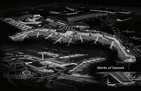
Works of Samuel
TABLE OF CONTENTS EWR: Newark Airport Master Planning
.
.
.
.
.
.
.
.
.
.
.
1
LGA: LaGuardia Airport - Terminal C .
.
.
.
.
.
.
.
.
.
.
11
JFK: Terminal 4 .
.
.
.
.
.
.
.
.
.
.
.
.
.
.
.
.
25
JFK: Terminal 6 .
.
.
.
.
.
.
.
.
.
.
.
.
.
.
.
.
35
Kuwait International Airport: Terminal 2
.
.
.
.
.
.
.
.
.
.
.
63
GTAA: Terminal 1 Air Canada
.
.
.
.
.
.
.
.
.
.
.
.
.
75
Changi Airport: Terminal 2 & 3
.
.
.
.
.
.
.
.
.
.
.
.
.
85
Changi Airport: Railway System .
.
.
.
.
.
.
.
.
.
.
.
.
91
Amtrak Railway: ADA Compiance
.
.
.
.
.
.
.
.
.
.
.
.
93
Penn Station: 32 Street Entry .
.
.
.
.
.
.
.
.
.
.
.
.
95
.
4
EWR: Newark Airport Master Planning - Transportation
5 2
EWR Master Plan Concepts Explored by PANYNJ
EWR Master Plan Concepts Explored by PANYNJ
Concept 2 Triggered from This Concept
Concept 2 Central Processor Triggered from This Concept
6
6
Additional Plan Concepts Additional EWR EWR MasterMaster Plan Concepts Explored byExplored United by United
7
7 4
SS2 JA1 SS5 JA2
Option Option 1 1 END STATE EWR MASTERPLAN AIRCRAFT PARAMETERS OF DESIGN TERMINAL / CONCONOURSE
AIRCRAFT LINEAR FRONTAGE (LF)
MAX MAX NB AIRCRAFT INTERNATION AL WB CONFIGURATION AIRCRAFT (ADG III) (ADG V) *
T1
A
800
5
T1
B
4,900
33
6
T2
C
5,392
37
17
T2
D
4,529
31
15
T2
E
5,382
37
17
T2
F
4,497
31
10
25,500
174
67
TOTAL:
2
* REDUCES NB AIRCRAFT COUNT
WALKING DISTANCE PATH
DISTANCE FT
( T O F UR T H E ST GA T E )
T1 HH - A
2,500
T1 HH - B
1,500
T2 HH - C
3,000
T2 HH - D
3,000
T2 HH - E
4,300
T2 HH - F
5,500
8
8
SS1 SS1 JA5 Option 1 – Potential Phasing Strategy JA5 Option 1 – Potential Phasing Strategy SS1 JA5 Option 1 – Potential Phasing Strategy
Option 1 - Phasing Strategy
Phase 1 Phase 1
Phase 2 Phase 2
Phase 3 Phase 3
Phase 4 Phase 4
Phase 1
Phase 2
Phase 3
Phase 4
Phase 5 Phase 5
Phase 6 Phase 6
End State End State
Phase 5
Phase 6
End State
Note: Phasing durationsdurations are indicative only Note: Phasing are indicative only
Master Planning Statement
10
Note: Phasing durations are indicative I worked on the development of a only comprehensive master plan concept with Corgan for Newark Liberty International Airport (EWR), exploring the integration of Terminals A, B, and C into a single headhouse with four concourses to accommodate 157–174 gates serving both international and domestic flights, including Federal Inspection Services (FIS) for international arrivals. The concept addressed terminal capacity, passenger flow optimization, gate allocation, security screening enhancements, baggage handling systems, and airside/landside connectivity. The master plan incorporated the existing Terminal 1 with the new Terminal 2 design, linking the two headhouses. It also integrated sustainability measures, operational efficiency improvements, and flexibility for future growth—ensuring the terminal meets evolving industry standards and passenger expectations..
10 10
9 6
SS3 JA4 SS6 JA3 SS7 JA6 SS8 JA7 SS9 SS11 JA8
Option 2 Option 2 - Phasing Strategy END STATE EWR MASTERPLAN AIRCRAFT PARAMETERS OF DESIGN
MAX AIRCRAFT MAX NB TERMINAL / LINEAR AIRCRAFT INTERNATIONAL CONCONOURSE FRONTAGE CONFIGURAT WB AIRCRAFT (LF) ION (ADG III) (ADG V) * T1
A
800
5
2
T1
B
5,350
36
6
T2
C
3,600
24
12
T2
D
4,400
29
14
T2
E
4,400
28
14
T2
F
2,300
25
12
T2
G
1,500
10
5
22,350
157
65
TOTAL:
WALKING DISTANCE PATH
(T O F UR T H ES T G A T E )
DISTANCE FT
T1 HH - A
2,500
T1 HH - B
1,500
T2 HH - C
2,800
T2 HH - D
2,500
T2 HH - E
2,300
T2 HH - F
3,000
T2 HH - G
2,600
12
10
JA9 SS10 JA10
Option 2 - Terminal 1 FIS Expansion Options
Option 2 - Terminal 1 FIS Expansion Options
Option 1 ( FIS North of T1)
Option 2 ( FIS South of T1)
14
11 8
SS12 SS13 JA11 SS15 SS16 JA12
Option 2 - Phasing Strategy Option 2 - Phasing Strategy
Phase 1
Phase 2
Phase 3
Phase 5
Phase 6
End State
Phase 4
Note: Phasing durations are indicative only
15
12
13
14
LGA: LaGuardia Airport - Terminal C
- Transportation
Aerial View from East 15 12
16
LaGuardia Aerial
Existing Terminals C and D Aerial
EXISTING SITE PLAN
SITE PLAN
4
SITE AND AIRFIELD PLANNING
EXISTING SITE PLAN EXISTING SITE PLAN
CTB & DELTA SITE PLAN
DUAL TAXILANES
AIRCRAFT START UP POSITIONS 17 14
18
PULL THROUGH DEICE PLAN
ATCT SHADOW STUDY
PART 77 STUDY
7460 PLAN WITH CRANE MOVEMENT AREA
19
20
PHASE 1
PHASE 4
PHASE 8
PHASE 9
34
PHASING
PHASE 5
PHASE 6
PHASE 10
PHASE 11 21 18
ARRIVALS LEVEL FLOOR PLAN
DEPARTURES LEVEL FLOOR PLAN
I assisted with both the master planning and construction documents for LaGuardia Airport’s Terminal C redevelopment. The phased delivery approach began with the construction of Concourse G, followed by the other concourses, all coordinated with the development of the centralized headhouse. This sequencing allowed for smooth operational transitions and maintained terminal functionality throughout construction. My work supported detailed planning and documentation to ensure efficient phasing, constructibility, and integration between the headhouse and each concourse, resulting in a new facility with a total of 37 gates.
22
SECURITY CHECKPOINT AND CONNECTOR LEVEL FLOOR PLAN
SKY CLUB LEVEL FLOOR PLAN
23 20
SOUTHEAST VIEW
NORTHEAST VIEW
1
NORTHWEST VIEW
SOUTHWEST SOUTHWEST VIEW VIEW
1 1
24
12
14 14
HEADHOUSE BUILDING SECTION The headhouse of LaGuardia’s Terminal C serves SECTION as the HEADHOUSE BUILDING central hub for arrivals, departures, security screening, and baggage handling. Spanning approximately 850,000 square feet, it provides a spacious, light-filled environment designed to enhance passenger experience and streamline terminal operations. The headhouse seamlessly connects to four concourses, facilitating efficient passenger flow and easy access to gates while integrating modern amenities and sustainable design features.
25 22
26
Departure Level view to Concessions Mezzanine
Conessions Mezzanine to Departure Gates Below
Check-In Hall
Departure Gate Holdroom
Airside Connector to Concourses and Gates
Baggage Claim Hall
Departures Roadway
Departures Roadway 27 24
52
TERMINAL 4
New York, New York - Transportation
JFK Terminal - 4
-Transportation
65 New International Airport (JFK) in New York. The new constructed $1.4 billion terminal New International Airport (JFK) in New York. The new constructed $1.4 billion complex combines Delta’s processes at JFK, allowing the airline to travel out of old facilities terminalincomplex combines Delta’s processes at JFK, allowing the airline to Terminal 3.
travel out of old facilities in Terminal 3.
Terminal 4 by nearly one third to 1.94 million square feet, and gives Delta the ability to
Terminalaccommodate 4 by nearlyall one to 1.94 million feet, and Delta of third their international flightssquare from Terminal 4. Itgives involves the the extension integration of existing services into one full-capacity facility, including: ability toand accommodate all of their international flights from Terminal 4. Itnine in- newly constructed passenger gates in addition to seven original, renovated gates; a new baggage volves the extension and integration of existing services into one full-capacity system; and the consolidation of existing security checkpoints. facility, including: nine newly constructed passenger gates in addition to seven original, renovated gates; a new baggage system; and the consolidation of ArupSOM architect of record was the designer of the original Terminal 4 building and I existing security checkpoints. worked on the Design and Construction Documentation for ArupSOM architect of record for Terminal 4 building which opened in 2001. This latest project includes the expansion of ArupSOM architect of record was designer the original 4 build-also Terminal 4’s Concourse B and thethe addition of new of security facilities. Terminal The redevelopment ing and features Samuelexpanded Ness worked onareas, the Design ConstructionDelta Documentation shopping the newand 24,000-square-foot Sky Club, and new for ArupSOM architect of record for Terminal 4 building which opened in 2001. to domestic baggage claim facilities to speed the transfer of passengers from international domestic flights. This latest project includes the expansion of Terminal 4’s Concourse B and the
addition of new security facilities. The redevelopment also features expanded shopping areas, the new 24,000-square-foot Delta Sky Club, and new domestic baggage claim facilities to speed the transfer of passengers from international 53 26 to domestic flights. 63
62
62 54 62
55 28
64
64 5664
JOHN JOHNF.F.KENNEDY KENNEDY TERMINAL TERMINAL4 4
IN
- Transportation
JOHN F. KENNEDY TERMINAL 4
INTERNATIONAL AIRPORT New York, New York - Transportation
65
JOHN F. KE TERMINAL
57 30
JOHN F. KENNEDY TERMINAL 4
58
INTERNATIONAL A New York,
- Tra
67 59 32
- Transportation - Transportation
New International Airpo terminal complex comb travel out of old faciliti
Terminal 4 by nearly on ability to accommodate volves the extension a facility, including: nine en original, renovated existing security check
60
ArupSOM architect of ing and Samuel Ness w for ArupSOM architect This latest project inclu addition of new securit shopping areas, the ne baggage claim facilitie to domestic flights. 69
69
ort (JFK) in New York. The new constructed $1.4 billion bines Delta’s processes at JFK, allowing the airline to ies in Terminal 3.
ne third to 1.94 million square feet, and gives Delta the e all of their international flights from Terminal 4. It inand integration of existing services into one full-capacity e newly constructed passenger gates in addition to sevgates; a new baggage system; and the consolidation of kpoints.
record was the designer of the original Terminal 4 buildworked on the Design and Construction Documentation of record for Terminal 4 building which opened in 2001. udes the expansion of Terminal 4’s Concourse B and the ty facilities. The redevelopment also features expanded ew 24,000-square-foot Delta Sky Club, and new domestic es to speed the transfer of passengers from international 63
61 34
70
JFK Terminal - 6
- Transportation
71 36
EXPANSION JOINT SCHEDULE FLOOR EXPANSION JOINT COVER ASSEMBLIES
TYPE
FLOOR FINISH
EJ-F1 2
GENERAL PLANPLAN NOTES NOTES
EXPANSION JOINT SCHEDULE (CONT) JOINT COVER FINISH
JOINT WIDTH
VAPOR BARRIER
FIRE BARRIER
REFERENCED DETAIL
NOTE
1.
ROOF EXPANSION JOINT COVER ASSEMBLIES
TYPE
ROOF FINISH
JOINT COVER FINISH
JOINT WIDTH
VAPOR BARRIER
FIRE BARRIER
2.
NOTE
REFERENCED DETAIL
777-9
CARPET / CARPET
STAINLESS STEEL
3"
YES
2 HRS
3 / A19.0914-01
MM SYSTEM MODEL: LSSB-NB 3-1.5
EJ-R1
KEE ROOFING
KEE ROOFING
3"
YES
3 / A19.0911-18
TYP ROOF RS-01
EJ-F1A
CARPET / PORCELAIN TILE
STAINLESS STEEL
3"
YES
2 HRS
3 / A19.0914-01 (SIM)
MM SYSTEM MODEL: LSSB-NB 3-1.5
EJ-R1A
KEE ROOFING
KEE ROOFING
3"
YES
1 / A19.0911-18
TYP ROOF RS-01 TRANSITION TO EXIST ROOF
EJ-F2
PORCELAIN TILE / PORCELAIN TILE
PORCELAIN TILE INSET
3"
YES
2 HRS
2 / A19.0914-01
MM SYSTEM MODEL: PDS-300
EJ-R2
KEE ROOFING
KEE ROOFING
3"
YES
3 / A19.0911-18
TYP ROOF RS-02
EJ-F3
CARPET / PORCELAIN TILE
STAINLESS STEEL
3"
YES
2 HRS
1 / A19.0914-01
MM SYSTEM MODEL: LSSB-NB 3-1.5
EJ-R2A
KEE ROOFING
KEE ROOFING
3"
YES
6 / A19.0911-18
TYP ROOF RS-02
EJ-F4
CONCRETE SIDEWALK / ROADWAY
STAINLESS STEEL
3"
YES
NA
3 / A19.0914-01
MM SYSTEM MODEL: DIH-300
EJ-R3
KEE ROOFING
KEE ROOFING
3"
YES
4 / A19.0911-17
FLAT ROOF WITH CONCRETE ON METAL DECK
EJ-R4
KEE ROOFING
NEOPRENE
3"
YES
2 / A19.0911-21
HORIZONTAL EXPANSION JOINT IN OCULUS SKYLIGHT CURB
2
EJ-R4A
KEE ROOFING
KEE ROOFING
3"
YES
2 / A19.0911-18
HORIZONTAL EXPANSION JOINT IN OCULUS SKYLIGHT CURB
WALL EXPANSION JOINT COVER ASSEMBLIES
EJ-R5
KEE ROOFING
KEE ROOFING
3"
YES
3 / A19.0914-03
ROOF TO CURTAIN WALL WT-02 AT FIXED BRIDGE
STOP
Fo ld e d
d Fo lde 7 77 -9
TYPE
NOTE
WALL FINISH
JOINT COVER FINISH
JOINT WIDTH
VAPOR BARRIER
FIRE BARRIER
REFERENCED DETAIL
EJ-R5A
KEE ROOFING
KEE ROOFING
3"
YES
3 / A19.0911-18
WT-1 / WT-1
ALUM + SILICONE GASKET
3"
YES
NA
5 / A19.0914-02
COLOR TO MATCH WALL FINISH
EJ-R5B
KEE ROOFING
KEE ROOFING
3"
YES
2 / A19.0911-17
EJ-W1A
WT-1 / WT-1
ALUM + SILICONE GASKET
3"
YES
NA
3 / A19.0914-02 (154O)
COLOR TO MATCH WALL FINISH
EJ-R5C
KEE ROOFING
KEE ROOFING
3"
YES
2 / A19.0911-17
EJ-W2
WT-2 / WT-2
ALUM + SILICONE GASKET
3"
YES
NA
5 / A19.0914-02 (SIM)
COLOR TO MATCH WALL FINISH
EJ-R5D
KEE ROOFING
KEE ROOFING
3"
YES
3 / A19.0911-17
EJ-W2A
WT-2 / WT-2
3"
YES
NA
1 / A19.0914-03
COLOR TO MATCH WALL FINISH
CEILING / SOFFIT FINISH
JOINT COVER FINISH
JOINT WIDTH
VAPOR BARRIER
FIRE BARRIER
ALUM PANEL / ALUM PANEL
NEOPRENE
3"
NA
NA
EJ-W2B
STOP
ALUM + SILICONE GASKET
WT-2 / WT-6
ALUM + SILICONE GASKET
3"
YES
NA
2 / A19.0914-03
EJ-W2C
WT-2 / WT-6
ALUM + SILICONE GASKET
3"
YES
NA
2/ A19.0914-03
STOP
EJ-W3
ROOF TRANSITION AT SCREEN WALL
6. 7.
WALL TRANSITION TO EXISTING LOWER ROOF
8. 9.
ROOF TRANSITION TO EXISTING BUILDING WALL
3
10.
ROOF TRANSITION TO WALL
3
5.
COLOR TO MATCH WALL FINISH COLOR TO MATCH WALL FINISH
3
COLOR TO MATCH WALL FINISH
WT-3 / WT-3
ALUM + SILICONE GASKET
3"
YES
2 HRS
9 / A19.0914.02
EJ-W3A
WT-3 / WT-3
ALUM + SILICONE GASKET
3"
YES
NA
2 / A19.0914-02
COLOR TO MATCH WALL FINISH
EJ-W4
WT-4 / WT-4
ALUM + SILICONE GASKET
3"
YES
NA
3 / A19.0914-02
COLOR TO MATCH WALL FINISH
EJ-W4A
WT-4 / WT-7
ALUM + SILICONE GASKET
3"
YES
NA
3 / A19.0914-02 (154o)
COLOR TO MATCH WALL FINISH
EJ-W4B
WT-4 / WT-7
ALUM + SILICONE GASKET
3"
YES
NA
12 / A19.0914-02
COLOR TO MATCH WALL FINISH
EJ-W4C
WT-4 / WT-1
ALUM + SILICONE GASKET
3"
YES
NA
1 / A19.0914-04
COLOR TO MATCH WALL FINISH
EJ-W6
WT-6 / WT-2
ALUM + SILICONE GASKET
3"
YES
2 HRS
2 / A19.0914-03
COLOR TO MATCH WALL FINISH
EJ-W7
WT-7 / WT-7
ALUM + SILICONE GASKET
3"
YES
NA
1 / A19.0914-02
COLOR TO MATCH WALL FINISH
EJ-W8
ELASTOMERIC COATING / PLYWOOD
ALUM + SILICONE GASKET
3"
YES
NA
10 / A19.0914-02
COLOR TO MATCH WALL FINISH
EJ-W9A
WT-4 / EXIST
ALUM + SILICONE GASKET
3"
YES
NA
6 / A19.0914-03
T5 TRANSITION, COLOR TO MATCH WALL FINISH
EJ-W9B
WT-4 / EXIST
ALUM + SILICONE GASKET
3"
YES
NA
6 / A19.0914-03
T5 TRANSITION, COLOR TO MATCH WALL FINISH
3
1
CEILING / SOFFIT EXPANSION JOINT COVER ASSEMBLIES
TYPE
1
EJ-C1
NOTE
REFERENCED DETAIL
COLOR TO MATCH SOFFIT COLOR
STOP
T6-9B
STOP
3
4.
STOP
77 7 -9
Fo
ld ed
777-9 Folded
EJ-W1
3.
BASEPOINT COORDINATES FOR W.P. SURVEY ARE: N/S 172451' 9 15/256", E/W 1045613' ' 105/128" BUILDING ENCLOSURE PACKAGE SCOPE INCLUDES VERTI AND HORIZONTAL ENCLOSURES. THE VERTICAL SYSTEMS INCLUDE BUT ARE NOT LIMITED TO: EXTERIOR MASONRY, CURTAINWALL, STOREFRONT, AND COLD FORMED METAL FRAMING. THE HORIZONTAL ENCLOSURE SYSTEMS INCLU BUT ARE NOT LIMITED TO: ETFE SKYLIGHTS, ALUMINUM COPINGS/ FLASHINGS, SINGLE PLY MEMBRANE WITH EXTRUDED POLYSTYRENE INSULATION, AS WELL AS ETFE CURBSIDE AND PEDESTRIAN WALKWAY CANOPIES. REFER TO FIT OUT YR-6006-22 & CORE ARCHITECTURE YR-6006-20 PACKAGES FOR CORE AND INTERIOR FITOUT. SCOPE ITEMS SHOWN ARE FOR REFERENCE ONL REFER TO SUPERSTRUCTURE YR-6006-18 PACKAGE FOR EXTERIOR STAIRS AND RAILINGS. MISC. METALS & CONCR CURBS. OUT OF SCOPE ITEMS ARE SHOWN FOR REFEREN ONLY. REFER TO PILES AND FOUNDATIONS YR-6006-16 PACKAGE FOR CONCRETE GRADE BEAM, FOUDATIONS, AND PILE CAPS. REFER TO UNDERGROUD WATERPROOFING FOR ADDITIONAL INFORMATION. A ALL ROOF SLOPES ARE 1/4" / 12" UNLESS NOTED OTHERW REFER TO 5/A19.0911-04 FOR TYPICAL DRAIN SLOPES AND FLASHING. ALL ROOFING IS RS-02 SYSTEM UNLESS NOTED OTHERWIS ALL EQUIPMENT, ROOF WALKING PADS, HATCHES, VENTS DRAINS, AND FIXTURES TO BE COORDINATED WITH FINAL PHOTOVOLTAIC PANEL LAYOUT CONTRACTOR TO DETERMINE INSULATION ELEVATIONS BASED ON MINIMUM AND MAXIMUM THICKNESSES LISTED DETAILS AND BASED ON 4-WAY SLOPED SYSTEM
T6-9A
STOP
-8 T6
T6-1A
D/ A19.0501-01
STOP
STOP
7 77 -9 ld ed Fo 777-9 Folded
T6-2 ed
PHASE 1
STOP
Fo ld
PHASE 2
STOP 77 7 -9
STOP 1
MPH
STOP
STOP
STOP
20
STOP
STOP
3
777-9 Folded
T6-4
STOP L5
KEYNOTES
STOP
T5-30
T6-3
T6-6
T6-7
T6-8
1
1
1
TER MIN AL 6
1
TER MIN A
T6-5
STOP 1
T6-2
C/ A19.0501-01
3
STOP
1
EJ-R5A
EJ-R2
T8 REC IRC
EJ-R2
EJ-R2
EJ-R4
DN
1
LANDSCAPE
EJ-R5D
T7 LIFT STATION
TRITURATOR BUILDING UC
K
SIDEWALK/EMERGENCY ACCESS ROAD
EX IT
EJ-R4
EX IT
4/3/2024 4:41:21 PM
PHASE 2
EJ-R1A WEST LIFT STATION
EXISTING TERMINAL 5
EJ-R2
EXISTING T7 AIRTRAIN
PHASE 1
DROP-OFF LANE
EJ-R5C
EJ-R2
DR
PO
PA
IN RK
PIC KU
P
P
T5 ARRIVALS SIDEWALK
XI TA
P
LA NE
SIDEWALK/EMERG ENCY ACCES S ROAD
BUS PICK-UP/DROP-OFF LANE
XI
EJ-R5B
V
LA NE
IN RK
G
LAN E
FH V
EX PO
NG PA RKI
IST
V
B/ A19.0501-01 RE
FUG
E
AR EA
EXISTING YELLOW GARAGE
FH V
FHV/POV /TWA/ T6 DEPARTURE POV TRUCK/TAXI/T5/FHV/
FH V
PI C KU
FH V
P
LAN E
T5
FH V
PI C KU
P
.T 5A
IRT RA PO
EXPANSION JOINT LEGEND
XI
TA
V
I
PO PIC KU
LA NE
EXISTING TWA
FH V
G
PA
V
FF
I
PO
PI C KU
-O
TA
V
PO
FH V
OP
I
LA
EXISTING T7 ORANGE GARAGE
A
TAX
ARRIV AL S T6
ARRIV AL S
T6
EL
.P EC
NT
PLAZ
TAX
RIV AL S
TAX
AR
EJ-R1A
T6 DEPARTURES
A19.0305LEVEL 4.0 ROOF PLAN - OVERALL - EXPANSION JOINT
TRUCK
E/ A19.0501-01
TR
T5 T5
INDICATES WALL EXPANSION JOINT COVER
INDICATES OCULUS CURB EXPANSION JOINT COVER
EXISTING T5 AIRTRAIN PEDESTRIAN BRIDGE
IN
INDICATES FLOOR EXPANSION JOINT COVER TW
V
TW
A/ TR
A/ TR
UC K
UC K
/TA
/TA
XI
INDICATES ROOF EXPANSION JOINT COVER
XI
LAN E
72 0'
25'
60'
120'
STOP
GENERAL PLANPLAN NOTES NO 1.
2
STOP
2.
STOP
25
24.1
24
4.
5.
R2 23 22.10 22.1 22 21.16
21
20.1
20
17
3
16.5 16
15
14
13
12
11
10
09
08.8 08
07
06
e11e10
05
04
03
02
01
6. 7. 8. 9.
4 A19.0703-05
8/ A19.0501-04
8/ A
5
501
3
19.0
4'
1 A19.0703-02
eE
1 A19.0805-04
127
13'
1
eD
SLOPE
eL
e2
9/ A
9 A19.0805-03
T
19.0
501 -0
5
1
eC
12' - 6"
eM 4/ A 19.0 10 501 -05 A19.0805-06
U
1
e6
10'
V
11.
LEVEL 4.0 ROOF - ROOF PLAN PH 1 1" = 30'-0"
1
3 A19.0708-01
1
4 A19.0703-04
1
10.
mB.3
7'
5/ A
51'a
-05
2
REFER TO 1/A19.305-1
-05
mE 19.0
501 -0
1
X
501
2' 6/ A
W
e7
19.0
MATCH LINE
mC.12
7/ A
9 A19.0805-05
1'
19.0
STOP
2
1
501 -0
5
mA
g5C g5D
3.
REFER TO 3/A19.305-1
SLOPE 17' - 6"
26
2
MATCH LINE
STOP
PHASE 1
PHASE 2
3
BASEPOINT COORDINATES FOR W.P. SUR 172451' 9 15/256", E/W 1045613' ' 105/128" BUILDING ENCLOSURE PACKAGE SCOPE AND HORIZONTAL ENCLOSURES. THE VER INCLUDE BUT ARE NOT LIMITED TO: EXTER CURTAINWALL, STOREFRONT, AND COLD FRAMING. THE HORIZONTAL ENCLOSURE BUT ARE NOT LIMITED TO: ETFE SKYLIGH COPINGS/ FLASHINGS, SINGLE PLY MEMB EXTRUDED POLYSTYRENE INSULATION, A CURBSIDE AND PEDESTRIAN WALKWAY C REFER TO FIT OUT YR-6006-22 & CORE AR YR-6006-20 PACKAGES FOR CORE AND INT FITOUT. SCOPE ITEMS SHOWN ARE FOR REFER TO SUPERSTRUCTURE YR-6006-18 EXTERIOR STAIRS AND RAILINGS. MISC. M CURBS. OUT OF SCOPE ITEMS ARE SHOW ONLY. REFER TO PILES AND FOUNDATIONS YR-6 FOR CONCRETE GRADE BEAM, FOUDATIO CAPS. REFER TO UNDERGROUD WATER ADDITIONAL INFORMATION. A ALL ROOF SLOPES ARE 1/4" / 12" UNLESS DR REFER TO 5/A19.0911-04 FOR TYPICAL DRA FLASHING. ALL ROOFING IS RS-02 SYSTEM UNLESS N ALL EQUIPMENT, ROOF WALKING PADS, H DRAINS, AND FIXTURES TO BE COORDINA PHOTOVOLTAIC PANEL LAYOUT LAYOUT. CONTRACTOR TO DETERMINE INSULATIO BASED ON MINIMUM AND MAXIMUM THICK DETAILS AND BASED ON 4-WAY SLOPED S ROOFS COMPLY WITH LOCAL LAW 92 /94. PHOTOVOLTAIC PANEL LAYOUT REFER TO DESIGN PACKAGE.
2
eK
S
R.5
e1
LEVEL 4.0 - ROOF PLAN PH 1 - ENCLOSURE_T5i CONNECTION 1" = 30'-0"
eJ e2'
DN
Q
e1'
eF eC P 3
eQ.17
eH
O
KEYNOTES A121
eR eG
FULLY GROUTED CMU WITH CFRP P INSIDE FACE OF THE WALL TO THE CONCRETE DECK ABOVE. REFER T PACKAGE YR-6006-18-003 FOR DETA
eB eA
2
19
eQ 18
3
3
RJ
RJ
RJ
RV
NA
NA
STS
O POD
IUM
eP
1
ANTENNA FARM
8.2 2°
e17 e16
64
58
eN
e15
e14 EL. 84' - 6 1/4"
AR
RIV AL S
e11 PL AZ A
e10
8 A19.0805-02
127 DR O
POF F
LA NE
e9
ORANGE GARAGE e8
LA N
E
PA
K R
FH V
G IN
PA
PIC KU P
K R
G IN
REFER TO A0301 - 1.0 FOR UNFOLDED ELEVATION MARKS
FH V
LA NE
mE
PO V
PIC KU P
LA N
e5
ING T
FH V
V
E
T5 AIR T
e4
EX IST
PO
5A IR T
PO V
RA IN
7.3 8°
eE
XI TA
eC
2 A19.0305-1
eD
CFRP; SEE KEYNOTE A121
SIDA LINE
XI TA
EXISTING BUILDINGS PHASE NIS
TAXI
PIC KU P
XI TA
TAXI
V
OPEN TO BELOW ANTENNA FARM
TAXI
PO
RA IN BR IDG E
PLAN LEGEND
4/3/2024 4:42:50 PM
A19.0305-1 LEVEL 4.0 ROOF PLAN PH 1
e13
EQUIPMENT PLATFO
eB eA
EQUIPMENT PIT
73 38
e3-3 e3.2
e3 e2
DEPRESSED SLAB
ROOF MAINTENANCE
SMOKE CONTROL EQ
e1
0'
25'
60'
120'
CMU WALL WITH CFR
DESIGN
74
OPTION 1 ARRIVAL LEVEL
OPTION 3 ARRIVAL LEVEL
OPTION 1 DEPARTURE LEVEL
OPTION 3 DEPARTURE LEVEL
STRUCTURAL & MEP
A 34 0-3 00
A340-300
SKETCH PHASE 2
PHASE 1
3/ A201
13
12
11
10
9
08
07
3' - 2" TYP 23' - 10 3/4"
06
05
23' - 7 1/2" EQ
EQ
04
EQ
03
02
EQ
EQ
01'''
01''
01
EQ 30' - 3 1/8"
40' - 6"
A
55
54
53
52
51
50
49
48
47
46
45
44
43
42
41
40
39
38
37
36
35
34
33
30' - 0" TYP 32
31
B 30
29
28
27
26
25
24
23.1
23
22
21
20
19
18
17
16
15
41' - 6 7/8"
56
14
9' - 3 3/4"
7' - 5 7/8" 26' - 3"
5' - 1"
6' - 10 1/4"
14' - 11"
C
D E
10' - 4"
57
30' - 6 7/8"
EQ EQ EQ EQ EQ EQ EQ 58
F
37' - 9 3/8"
21' - 10 7/8"
2' - 10" 26' - 7"
8' - 2"
H
28' - 9 1/2" 33' - 8 3/4"
28' - 9 1/2" 33' - 8 3/4"
G
J J' K L M
37' - 6 7/8"
60' - 0" TYP.
N
14'
60' - 0"
P
13'
12'
60' -0 TYP "
P' Q
60' - 0"
11'
10'
56' - 0"
G' 09'
08'
56' - 0"
E'
07'
06'
56' - 0"
60' - 0"
202
C'
02'
B'
1/ A
04'
PO V
26' - 6"
201
0' 2
05'
1/4"
D' 1/ A
FHV
8' 4"
BIM
R
A'
01'
Project Number: 18143.0000
NORTH
STRUCTURAL GRID LAYOUT - LEVELDRAFT1 - PH1 IN PROGRESS 1" = 40'-0" 04/29/19
This Document was produced by or under the direct supervision of William J. Liese.
This document is incomplete and may not be used for regulatory approval, permit or construction.
75 40
MEP
76
PRELIMINARY MECHENICAL AIR DISTRUBUTION
77 42
BUILDING LIFE SAFETY / EGRESS
78
BUILDING LIFE SAFETY / EGRESS EGRESS DISTANCES - LEVEL 1 - PHASE 2
VV
Maximum Travel Distance
Type
LIFE SAFETY LEGEND
PRIMARY
300
201' - 4"
C7
PRIMARY
300
181' - 7"
C8
PRIMARY
300
180' - 0"
SECTION BC 1016 EXIT ACCESS TRAVEL DISTANCE TABLE 1016.1 EXIT ACCESS TRAVEL DISTANCE OCCUPANCY WITH SPRINKLER SYSTEM (FT.) A SEE SECTION 1028.7 M, F-1 200 F-2, S-2 250 B 300
SECONDARY TRAVEL PATH
A
TRAVEL PATH NAME 1 HOUR FIRE SEPARATION
GG.1
2 HOUR FIRE SEPARATION
TABLE 1028.7 TRAVEL DISTANCE (SPRINKLERED) OCCUPANCY PRIMARY SECONDARY A-2, A-3 150 (FEET) 150 (FEET)
3 HOUR FIRE SEPARATION
PROJECT DATA
PROJECT NAME: PROJECT ADDRESS:
4 HOUR FIRE WALL
84
AA
GENERAL SHEET NOTES
PRIMARY TRAVEL PATH
Travel Path Distance
C6
FIRE SHUTTER
OWNER:
GG
AA.1
STAIR NUMBER: STR-30 STAIR CAPACITY: 72" / 0.3 = 240
83 BB
DESIGNATION OCCUPANCY GROUP
AREA DESCRIPTION
A
ASSEMBLY
RESTAURANTS, CONCOURSE, CIRCULATION, HOLDROOM AREAS, CONCESSION LOUNGE AREAS
B
BUSINESS
FLIGHT SERVICES AND OPERATION, ADMINISTRATIVE AND OFFICE
F-1
FACTORY INDUSTRIAL MODERATE-HAZARD
SUBSTATIONS
F-2
FACTORY INDUSTRIAL LOWHAZARD
MEP
M
MERCANTILE
RETAIL SHOPS (CONCESSIONS) NOT OPEN TO THE CONCOURSE
S-2
STORAGE (LOW HAZARD)
SUPPORT AREAS, STORAGE CLOSETS
IB
2014 NEW YORK CITY BUILDING CODE (NYCBC) 2013 ASME 17.1 -- SAFETY CODE FOR ELEVATORS AND ESCALATORS 2014 NEW YORK CITY ENERGY CONSERVATION CODE (NYCECC). INCLUDING REFERENCE STANDARDS AND THE RULES OF NEW YORK AND NEW YORK CITY LOCAL LAWS 2015 TENANT CONSTRUCTION REVIEW MANUAL (TCRM) LEED BD+C CORE AND SHELL V3 2010 LEED ADA STANDARDS FOR ACCESSIBLE DESIGN, AMERICAN WITH DISABILITIES ACT (ADA)
JFK TERMINAL 6 DEVELOPMENT JOHN F. KENNEDY AIRPORT QUEENS, NY 11430 VANTAGE GROUP
CORGAN ASSOCIATES ARCHITECTS PC 350 Fifth Avenue, Suite 5401 New York, NY 10118 T: 212-490-2930
475 Fifth Avenue New York NY
469 Seventh Avenue New York NY
1001 Avenue of America New York NY
PEOPLE PEOPLE
STAIR NUMBER: STR-31 STAIR CAPACITY: 72" / 0.3 = 240
212 West 35th Street New York NY
STAIR WIDTH: 72" PEOPLE PEOPLE
ACTUAL OCCUPANTS:
15950 N. Dallas Parkway Dallas TX
80
CC
OCCUPANCY GROUPS
CONSTRUCTION TYPE:
APPLICABLE CODES
STAIR WIDTH: 72"
ACTUAL OCCUPANTS: 81 FF
TYPE OF CONTRUCTION - 2014 NYCBC TABLE
STAIR NUMBER: STR-29 STAIR CAPACITY: 72" / 0.3 = 240
STAIR WIDTH: 72" PEOPLE PEOPLE
ACTUAL OCCUPANTS:
CC.1
79
550 Seventh Avenue New York NY STAIR WIDTH: 72"
STAIR NUMBER: STR-19 STAIR CAPACITY: 72" / 0.3 = 240
STANDBY DISTRIBUTION #3
STAIR NUMBER: STR-22 STAIR CAPACITY: 72" / 0.3 = 240
75
58
57
56
55
54
1981 Post Road Fairfield, CT
STAIR WIDTH: 72"
52
51
50
49
48
47
46
45
44
43
42
STAIR WIDTH: 72"
41
40
39
37 37
38
36.1 36.1
36 36
35 35
STAIR NUMBER: STR-16 STAIR CAPACITY: 72" / 0.3 = 240
STAIR CAPACITY: 72" / 0.3 = 240
STAIR WIDTH: 72"
STAIR NUMBER: STR-13 STAIR CAPACITY: 72" / 0.3 = 240
34 34 33 33
32 32
31 31
30 30
29 29
28 28
PEOPLE PEOPLE
ACTUAL OCCUPANTS:
PEOPLE PEOPLE
ACTUAL OCCUPANTS:
STAIR NUMBER: STR-12 STAIR CAPACITY: 72" / 0.3 =
STAIR WIDTH: 72"
PEOPLE PEOPLE
ACTUAL OCCUPANTS:
OUTBOUND BHS 161 (S-2) LOW - HAZARD
53
STAIR NUMBER: STR-18 STAIR CAPACITY: 72" / 0.3 = 240
PEOPLE PEOPLE
ACTUAL OCCUPANTS:
PEOPLE PEOPLE
74 59
PEOPLE PEOPLE
STAIR NUMBER: STR-21 STAIR CAPACITY: 72" / 0.3 = 240
STAIR WIDTH: 72"
ACTUAL OCCUPANTS:
40 Wall Street New York NY
STAIR WIDTH: 72"
ACTUAL OCCUPANTS:
919 (F-2) LOW - HAZARD OCCUPANCY
76
PEOPLE PEOPLE
ACTUAL OCCUPANTS:
PEOPLE PEOPLE
PHASE 1
STAIR WIDTH: 72"
STAIR WIDTH: 72"
PHASE 2
STAIR NUMBER: STR-25 STAIR CAPACITY: 72" / 0.3 = 240 ACTUAL OCCUPANTS:
77
STAIR NUMBER: STR-18 STAIR CAPACITY: 72" / 0.3 = 240
PHASE 1
PEOPLE PEOPLE
ACTUAL OCCUPANTS:
78
PHASE 2
STAIR NUMBER: STR-28 STAIR CAPACITY: 72" / 0.3 = 240
COVERED GSE DD
STAIR WIDTH: 72"
26
25
24
10/16/2019
PEOPLE PEOPLE
ACTUAL OCCUPANTS:
27
14600 Trinity Blvd Fort Worth, TX
23
22
STAIR WIDTH: 72"
STAIR NUMBER: STR-09 STAIR CAPACITY: 72" / 0.3 = 240
20
19
18
17
16
15 14.1
14
13
PEOPLE PEOPLE
STAIR NUMBER: STR-07 STAIR CAPACITY: 72" / 0.3 = 240
PEOPLE PEOPLE 12
STAIR WIDTH: 72"
ACTUAL OCCUPANTS:
STAIR WIDTH: 72"
ACTUAL OCCUPANTS:
21
STAIR NUMBER: STR-08 STAIR CAPACITY: 72" / 0.3 = 240
PEOPLE PEOPLE
ACTUAL OCCUPANTS:
ISSUES
INTERIM PDD SUBMISSION
STAIR WIDTH: 72" PEOPLE PEOPLE
ACTUAL OCCUPANTS:
11
10
09
08
07
06
05
04
02
03
01
ELEC. 173 (F-2) LOW - HAZARD OCCUPANCY MEP
CORGAN ASSOCIATES ARCHITECTS PC 350 Fifth Avenue, Suite 5401 New York, NY 10118 T: 212-490-2930
C8
154 (F-2) LOW - HAZARD OCCUPANCY
475 Fifth Avenue New York NY
EX2
EX2
This Document was produced by or under the authority of Registered Architect:
STAIR NUMBER: STR-06 STAIR CAPACITY: 72" / 0.3 = 240
DN
STAIR NUMBER: STR-05 STAIR CAPACITY: 72" / 0.3 = 240
This document is incomplete and may not be used for regulatory approval, permit or construction.
STAIR NUMBER: STR-10 STAIR CAPACITY: 72" / 0.3 = 240
STAIR NUMBER: STR-04 STAIR CAPACITY: 72" / 0.3 = 240
COVERED GSE
DN
DN
C C6
SUPPORT
OUTBOUND BHS
152 (S-2) LOW - HAZARD WASTE 1195 (S-2) LOW - HAZARD
10/16/2019 5:48:54 PM G01-03 FLOOR PLAN - LEVEL 1 ARRIVALS - PHASE 2 - LIFE SAFETY
73 MEP 1196 (F-2) LOW - HAZARD OCCUPANCY
71 72
C7
965 (S-2) LOW - HAZARD C.1
D LOADING DOCK SIDA
70.1 70
E
151 (S-2) LOW - HAZARD
BR1
R
AI TL3 1
T.1 L
ADA GATE
C4
WT MD 2
68
SUBSTATION #3
MEP
176 (F-2) LOW - HAZARD OCCUPANCY
156 (F-2) LOW - HAZARD OCCUPANCY
2
SUPPORT
MEP 2886 SF
926 (B) BUSINESS T DC
SHARED BSO 1268 (S-2) LOW - HAZARD
F A C1
C DN TO / UP / DEPA FROM RTUR ES
SEWER EJECTOR PUMP ROOM
K' C4 H
STAIR WIDTH: 72"
MEP
920 (F-2) LOW - HAZARD OCCUPANCY
STAIR NUMBER: STR-23 STAIR CAPACITY: 72" / 0.3 = 240
STAIR WIDTH: 72" PEOPLE PEOPLE
ACTUAL OCCUPANTS:
ARRIVALS
PEOPLE PEOPLE
MEP MEP 147 (F-2) LOW - HAZARD OCCUPANCY
A
CIRCULATION - LANDSIDE 20 (A-3) ASSEMBLY
12'
11'
927 (F-2) LOW - HAZARD OCCUPANCY
10'
Travel Path ID
84 GG.1
AA
GG
STAIR NUMBER: STR-30 STAIR CAPACITY: 72" / 0.3 = 240
83
STAIR WIDTH: 72" PEOPLE PEOPLE
ACTUAL OCCUPANTS:
AA.1
STAIR NUMBER: STR-31 STAIR CAPACITY: 72" / 0.3 = 240
81
Type
Maximum Travel Distance
LIFE SAFETY LEGEND
Travel Path Distance
L L
PRIMARY 150 SECONDARY 250
103' - 0" 149' - 5"
M M
PRIMARY 150 SECONDARY 250
126' - 6" 135' - 8"
N N
PRIMARY 150 SECONDARY 250
112' - 11" 116' - 11"
O O
PRIMARY 150 SECONDARY 250
146' - 9" 149' - 0"
TRAVEL PATH NAME 1 HOUR FIRE SEPARATION
FLIGHT SERVICES AND OPERATION, ADMINISTRATIVE AND OFFICE
F-1
FACTORY SUBSTATIONS INDUSTRIAL MODERATE-HAZARD
F-2
FACTORY INDUSTRIAL LOWHAZARD
MEP
M
MERCANTILE
RETAIL SHOPS (CONCESSIONS) NOT OPEN TO THE CONCOURSE
S-2
STORAGE (LOW HAZARD)
SUPPORT AREAS, STORAGE CLOSETS
CBP PRIMARY
A
1312 (A-3) ASSEMBLY
CBP SECONDARY 9 (B) BUSINESS
1 HOUR FIRE SEPARATION
F'
08''
2 HOUR FIRE SEPARATION 3 HOUR FIRE SEPARATION 4 HOUR FIRE WALL
08'
STAIR NUMBER: STR-03 STAIR CAPACITY: 72" / 0.3 = 240
E'
07'
ACTUAL OCCUPANTS:
STAIR NUMBER: STR-02 STAIR CAPACITY: 72" / 0.3 = 240
06' STAIR NUMBER: STR-14 STAIR CAPACITY: 72" / 0.3 = 240
ACTUAL OCCUPANTS:
STAIR WIDTH: 72" PEOPLE PEOPLE
ACTUAL OCCUPANTS:
STAIR NUMBER: STR-01 STAIR CAPACITY: 72" / 0.3 = 240
D'
05'
ELEC.
ACTUAL OCCUPANTS:
1114 (F-2) LOW - HAZARD OCCUPANCY
STAIR WIDTH: 72"
FIRE SHUTTER
PEOPLE PEOPLE
PEOPLE PEOPLE
STAIR WIDTH: 72" PEOPLE PEOPLE
C' 03'
STAIR WIDTH: 72" PEOPLE PEOPLE
B'
01'
2 HOUR FIRE SEPARATION
TABLE 1028.7 TRAVEL DISTANCE (SPRINKLERED) OCCUPANCY PRIMARY SECONDARY A-2, A-3 150 (FEET) 150 (FEET) PROJECT DATA
PROJECT NAME: PROJECT ADDRESS:
FIRE SHUTTER
OWNER:
OCCUPANCY GROUPS
CONSTRUCTION TYPE:
DESIGNATION OCCUPANCY GROUP
IB
APPLICABLE CODES 2014 NEW YORK CITY BUILDING CODE (NYCBC) 2013 ASME 17.1 -- SAFETY CODE FOR ELEVATORS AND ESCALATORS 2014 NEW YORK CITY ENERGY CONSERVATION CODE (NYCECC). INCLUDING REFERENCE STANDARDS AND THE RULES OF NEW YORK AND NEW YORK CITY LOCAL LAWS 2015 TENANT CONSTRUCTION REVIEW MANUAL (TCRM) LEED BD+C CORE AND SHELL V3 2010 LEED ADA STANDARDS FOR ACCESSIBLE DESIGN, AMERICAN WITH DISABILITIES ACT (ADA)
JFK TERMINAL 6 DEVELOPMENT JOHN F. KENNEDY AIRPORT QUEENS, NY 11430 VANTAGE GROUP
Travel Path ID
Maximum Travel Distance
Type
Travel Path Distance
A A
PRIMARY 150 SECONDARY 250
143' - 5" 154' - 4"
B B
PRIMARY 150 SECONDARY 250
94' - 3" 109' - 1"
C C
PRIMARY 150 SECONDARY 250
147' - 0" 152' - 0"
C1 C1
PRIMARY 150 SECONDARY 250
114' - 5" 134' - 3"
C2 C2
PRIMARY 150 SECONDARY 250
89' - 5" 91' - 0"
C3 C3
PRIMARY 150 SECONDARY 250
107' - 7" 172' - 7"
C4 C4
PRIMARY 150 SECONDARY 250
112' - 9" 147' - 3"
C5
PRIMARY
218' - 8"
300
CORGAN ASSOCIATES ARCHITECTS PC 350 Fifth Avenue, Suite 5401 New York, NY 10118 T: 212-490-2930
AREA DESCRIPTION
A
ASSEMBLY
RESTAURANTS, CONCOURSE, CIRCULATION, HOLDROOM AREAS, CONCESSION LOUNGE AREAS
B
BUSINESS
FLIGHT SERVICES AND OPERATION, ADMINISTRATIVE AND OFFICE
F-1
FACTORY INDUSTRIAL MODERATE-HAZARD
SUBSTATIONS
F-2
FACTORY INDUSTRIAL LOWHAZARD
MEP
M
MERCANTILE
RETAIL SHOPS (CONCESSIONS) NOT OPEN TO THE CONCOURSE
S-2
STORAGE (LOW HAZARD)
SUPPORT AREAS, STORAGE CLOSETS
This document is incomplete and may not be used for regulatory approval, permit or construction.
KEY PLAN
A'
02'
TYPE OF CONTRUCTION - 2014 NYCBC TABLE
EGRESS DISTANCES - LEVEL 1 - PHASE 1
STAIR WIDTH: 72"
04'
BSO STORAGE 659 (S-2) LOW - HAZARD
STAIR NUMBER: STR-11 STAIR CAPACITY: 72" / 0.3 = 240 ACTUAL OCCUPANTS:
TRAVEL PATH NAME
B
MEP
3 HOUR FIRE SEPARATION 4 HOUR FIRE WALL
BUSINESS
PRIMARY TRAVEL PATH
1091 (F-2) LOW - HAZARD OCCUPANCY
SECTION BC 1016 EXIT ACCESS TRAVEL DISTANCE TABLE 1016.1 EXIT ACCESS TRAVEL DISTANCE OCCUPANCY WITH SPRINKLER SYSTEM (FT.) A SEE SECTION 1028.7 M, F-1 200 F-2, S-2 250 B 300
SECONDARY TRAVEL PATH
A
B
09'
TELECOM SERVICE ENTRANCE ROOM #2 990 (F-2) LOW - HAZARD OCCUPANCY
GENERAL SHEET NOTES
PRIMARY TRAVEL PATH
RESTAURANTS, CONCOURSE, CIRCULATION, HOLDROOM AREAS, CONCESSION LOUNGE AREAS
SECONDARY TRAVEL PATH
G01-03
FIRE PUMP ROOM
ASSEMBLY
LIFE SAFETY LEGEND
18143.0200 JOB 10/16/19 DATE SHEET
928 (F-2) LOW - HAZARD OCCUPANCY
H' B
This Document was produced by or under the authority of Registered Architect:
William J. Liese
A
C2
CBP BAGGAGE CLAIM 11 (A-3) ASSEMBLY
CBP QUEUE 13 (A-3) ASSEMBLY
01''
EGRESS DISTANCES - LEVEL 2 - PHASE 2
IB
OCCUPANCY GROUPS
FLOOR PLAN LEVEL 1 ARRIVALS - PHASE 2 - LIFE SAFETY
13'
GAS METER ROOM
EMERGENCY SUBSTATION #3
154 (F-2) LOW - HAZARD OCCUPANCY
STAIR WIDTH: 72"
ACTUAL OCCUPANTS:
MEP 922 (F-2) LOW - HAZARD OCCUPANCY
PEOPLE PEOPLE
ACTUAL OCCUPANTS:
C
C1
14'
ELEC. 177 177 (F-2) LOW - HAZARD OCCUPANCY
STAIR NUMBER: STR-17 STAIR CAPACITY: 72" / 0.3 = 240
PLUMBING 921 (F-2) LOW - HAZARD OCCUPANCY
UTILITY CORRIDOR
CONSTRUCTION TYPE:
APPLICABLE CODES 2014 NEW YORK CITY BUILDING CODE (NYCBC) 2013 ASME 17.1 -- SAFETY CODE FOR ELEVATORS AND ESCALATORS 2014 NEW YORK CITY ENERGY CONSERVATION CODE (NYCECC). INCLUDING REFERENCE STANDARDS AND THE RULES OF NEW YORK AND NEW YORK CITY LOCAL LAWS 2015 TENANT CONSTRUCTION REVIEW MANUAL (TCRM) LEED BD+C CORE AND SHELL V3 2010 LEED ADA STANDARDS FOR ACCESSIBLE DESIGN, AMERICAN WITH DISABILITIES ACT (ADA)
J
GAS METER ROOM 924 (F-2) LOW - HAZARD OCCUPANCY
PEOPLE PEOPLE
STAIR NUMBER: STR-27 STAIR CAPACITY: 72" / 0.3 = 240
TYPE OF CONTRUCTION - 2014 NYCBC TABLE
FIRE WALL TO BE PROVIDED ADJACENT TO TERMINAL 5I
G
PEOPLE PEOPLE
925 (F-2) LOW - HAZARD OCCUPANCY
STAIR WIDTH: 72"
OWNER:
TERMINAL T5I EGRESS AIRSIDE DISCHARGE
L'
STAIR WIDTH: 72"
ACTUAL OCCUPANTS:
ISSUES
INTERIM PDD SUBMISSION
JFK TERMINAL 6 DEVELOPMENT JOHN F. KENNEDY AIRPORT QUEENS, NY 11430 VANTAGE GROUP
DESIGNATION OCCUPANCY GROUP AREA DESCRIPTION
STAIR NUMBER: STR-20 STAIR CAPACITY: 72" / 0.3 = 240
ELEC. 175 (F-2) LOW - HAZARD OCCUPANCY
STAIR NUMBER: STR-26 STAIR CAPACITY: 72" / 0.3 = 240
PROJECT NAME: PROJECT ADDRESS:
TERMINAL 5I EGRESS LANDSIDE DISCHARGE
SEE DRAWING G01-02
GOODS SCREENING 149 (S-2) LOW - HAZARD
14600 Trinity Blvd Fort Worth, TX
10/16/2019
PROJECT DATA
ELEC. 913 (F-2) LOW - HAZARD OCCUPANCY
PEOPLE PEOPLE
ACTUAL OCCUPANTS:
TABLE 1028.7 TRAVEL DISTANCE (SPRINKLERED) OCCUPANCY PRIMARY SECONDARY A-2, A-3 150 (FEET) 150 (FEET)
E
KEY PLAN STAIR WIDTH: 72"
C.1
5
RESTROOMS
G.1
60
STAIR NUMBER: STR-24 STAIR CAPACITY: 72" / 0.3 = 240 ACTUAL OCCUPANTS:
SEE DRAWING G01-03
61
EXIST TERMINING AL
1981 Post Road Fairfield, CT
SECTION BC 1016 EXIT ACCESS TRAVEL DISTANCE TABLE 1016.1 EXIT ACCESS TRAVEL DISTANCE OCCUPANCY WITH SPRINKLER SYSTEM (FT.) A SEE SECTION 1028.7 M, F-1 200 F-2, S-2 250 B 300
D
CONCESSIONS
G.1
10/16/2019 5:48:47 PM G01-02 FLOOR PLAN - LEVEL 1 ARRIVALS - PHASE 1 - LIFE SAFETY
62
TERMIN NEW AL 6
C2
T DC
RESTROOMS 63
40 Wall Street New York NY
01.11
GENERAL SHEET NOTES
C3
SID A
G.1
01.1
C
850 (A-3) ASSEMBLY
DN FROM CONCOURSE
f o
69
F
BR2 95.4
15950 N. Dallas Parkway Dallas TX
PEOPLE PEOPLE
02.1
BUSSING LOBBY 658 (A-3) ASSEMBLY
OUTBOUND BHS
161 (S-2) LOW - HAZARD
CONCESSIONS SUPPORT 158 (B) BUSINESS
STAIR WIDTH: 72"
550 Seventh Avenue New York NY INBOUND BHS 5 (S-2) LOW - HAZARD
DN
DN
John F Kennedy International Airport Queens, NY 11430
DN
JFK TERMINAL 6 DEVELOPMENT
EX3
EX3
SUPPORT
212 West 35th Street New York NY
PEOPLE PEOPLE
ACTUAL OCCUPANTS:
B
1001 Avenue of America New York NY
PEOPLE PEOPLE STAIR WIDTH: 72"
ACTUAL OCCUPANTS:
HH
1194 (S-2) LOW - HAZARD
STAIR WIDTH: 72"
ACTUAL OCCUPANTS: A
C3
EE
PEOPLE PEOPLE
ACTUAL OCCUPANTS:
William J. Liese
SUPPORT 150 (B) BUSINESS
469 Seventh Avenue New York NY
STAIR WIDTH: 72"
John F Kennedy International Airport Queens, NY 11430
EX1
JFK TERMINAL 6 DEVELOPMENT
EX1
FLOOR PLAN LEVEL 1 ARRIVALS - PHASE 1 - LIFE SAFETY 18143.0200 JOB 10/16/19 DATE SHEET
G01-02
475 Fifth Avenue New York NY
469 Seventh Avenue New York NY
1001 Avenue of America New York NY
212 West 35th Street New York NY
STAIR WIDTH: 72" PEOPLE PEOPLE
ACTUAL OCCUPANTS: BB STAIR NUMBER: STR-28 STAIR CAPACITY: 72" / 0.3 = 240
PEOPLE PEOPLE STAIR WIDTH: 72" STAIR NUMBER: STR-24 STAIR CAPACITY: 72" / 0.3 = 240
77
PEOPLE PEOPLE
ACTUAL OCCUPANTS: STAIR NUMBER: STR-22 STAIR CAPACITY: 72" / 0.3 = 240
PEOPLE PEOPLE
STAIR NUMBER: STR-20 STAIR CAPACITY: 72" / 0.3 = 240
76
1981 Post Road Fairfield, CT
STAIR WIDTH: 72"
STAIR NUMBER: STR-18 STAIR CAPACITY: 72" / 0.3 = 240
PEOPLE PEOPLE
ACTUAL OCCUPANTS: STAIR NUMBER: STR-21 STAIR CAPACITY: 72" / 0.3 = 240
75
40 Wall Street New York NY
STAIR WIDTH: 72"
ACTUAL OCCUPANTS:
PEOPLE PEOPLE
ACTUAL OCCUPANTS:
STAIR WIDTH: 72"
STAIR NUMBER: STR-19 STAIR CAPACITY: 72" / 0.3 = 240
PEOPLE PEOPLE
ACTUAL OCCUPANTS:
STAIR WIDTH: 72"
STAIR WIDTH: 72" PEOPLE PEOPLE
ACTUAL OCCUPANTS:
PHASE 1
HOLDROOMS
STAIR WIDTH: 72"
PHASE 2
DELUGE SYSTEM PROVIDED. REFER TO FIRE PROTECTION DRAWINGS
78 1043 (A-3) ASSEMBLY
DD
550 Seventh Avenue New York NY
PEOPLE PEOPLE
ACTUAL OCCUPANTS: O
STAIR NUMBER: STR-18 STAIR CAPACITY: 72" / 0.3 = 240
STAIR WIDTH: 72"
STAIR NUMBER: STR-16 STAIR CAPACITY: 72" / 0.3 = 240
59
58
57
56
55
54
53
52
51
50
49
48
47
46
45
44
43
42
41
40
39
38
37
36.1
36
35
34 33
32
31
30
29
PEOPLE PEOPLE
26
25
24
23
22
PEOPLE PEOPLE
STAIR NUMBER: STR-10 STAIR CAPACITY: 72" / 0.3 = 240
PEOPLE PEOPLE 21
STAIR WIDTH: 72"
ACTUAL OCCUPANTS:
ISSUES
10/16/2019 STAIR WIDTH: 72"INTERIM PDD SUBMISSION
STAIR NUMBER: STR-13 STAIR CAPACITY: 72" / 0.3 = 240 ACTUAL OCCUPANTS: 27
28
STAIR NUMBER: STR-08 STAIR CAPACITY: 72" / 0.3 = 240
STAIR WIDTH: 72"Trinity Blvd Fort Worth, TX 14600
ACTUAL OCCUPANTS:
STAIR WIDTH: 72" PEOPLE PEOPLE
ACTUAL OCCUPANTS:
74
STAIR NUMBER: STR-15 STAIR CAPACITY: 72" / 0.3 = 240
PEOPLE PEOPLE
ACTUAL OCCUPANTS:
PHASE 1
STAIR NUMBER: STR-25 STAIR CAPACITY: 72" / 0.3 = 240
79 CC.1
15950 N. Dallas Parkway Dallas TX
STAIR WIDTH: 72"
ACTUAL OCCUPANTS:
CC
PHASE 2
80
FF
20
19
18
17
16
DELUGE SYSTEM PROVIDED. REFER TO FIRE PROTECTION DRAWINGS
STAIR WIDTH: 72" PEOPLE PEOPLE
ACTUAL OCCUPANTS: 15 14.1
14
13
12
11
10
09
08
07
06
05
04
03
02
01
CORGAN ASSOCIATES ARCHITECTS PC 350 Fifth Avenue, Suite 5401 New York, NY 10118 T: 212-490-2930
RESTROOMS
O 475 Fifth Avenue New York NY
This Document was produced by or under the authority of Registered Architect:
EX1
469 Seventh Avenue New York NY
William J. Liese
HOLDROOMS 188 (A-3) ASSEMBLY
DELUGE SYSTEM PROVIDED. REFER TO FIRE PROTECTION DRAWINGS
DELUGE SYSTEM PROVIDED. REFER TO FIRE PROTECTION DRAWINGS
DELUGE This SYSTEM document is incomplete and may PROVIDED. REFER not be used forTOregulatory approval, FIREpermit PROTECTION or construction. DRAWINGS
HOLDROOMS 1067 (A-3) ASSEMBLY
1001 Avenue of America New York NY
A 212 West 35th Street New York NY
EX2
EX2
FROM AIRLINE CLUB ABOVE
I
15950 N. Dallas Parkway Dallas TX
CONCESSIONS
RESTROOMS
195 (A-2) ASSEMBLY
K
D
L
M
N
FIRE SHUTTER TO BE PROVIDED ATRIUM BREAK
HH
70
HOLDROOMS 62 (A-3) ASSEMBLY
M
71 72 70.1
K
RESTROOMS
F BR1
69
BR2 95.4
CONCESSIONS 184 (B) BUSINESS
T.1
CONCESSIONS 961 (A-2) ASSEMBLY
SUPPORT 1139 (B) BUSINESS F.1
68
OPEN TO BELOW
ACTUAL OCCUPANTS:
40 Wall Street New York NY C GENERAL SHEET NOTES
OPEN TO BELOW
F&B 1059 (A-2) ASSEMBLY
TERMIN NEW AL 6
EXIST TERMINING AL
C.1
D CIRCULATION - AIRSIDE PHASE 1 53 (A-3) ASSEMBLY J
F GENERAL RETAIL 83 (A-2) ASSEMBLY
UP
63
62
61
60
G BAR/CASUAL SEATING 1074 (A-2) ASSEMBLY
T.2
IDF (AIRLINE/VENDOR) 214 (F-2) LOW - HAZARD OCCUPANCY
ELEC.
ELEC. 1182 (F-2) LOW - HAZARD OCCUPANCY
ELEC. 217 (F-2) LOW - HAZARD OCCUPANCY
PA IDF 1184 (F-2) LOW - HAZARD OCCUPANCY
SUPPORT 218 (B) BUSINESS
PA IDF 1030 (F-2) LOW - HAZARD OCCUPANCY 213 (F-2) LOW - HAZARD OCCUPANCY
1032 (F-2) LOW - HAZARD OCCUPANCY
PA IDF
CONCESSIONS 1080 (A-2) ASSEMBLY
STAIR NUMBER: STR-23 STAIR CAPACITY: 72" / 0.3 = 240 ACTUAL OCCUPANTS:
STAIR WIDTH: 72" PEOPLE PEOPLE
CCONCOURSE
STAIR NUMBER: STR-03 STAIR CAPACITY: 72" / 0.3 = 240
F&B 662 (A-2) ASSEMBLY
ACTUAL OCCUPANTS:
12'
DN
ELEC.
RESTROOMS G'
ACTUAL OCCUPANTS:
STAIR WIDTH: 72" PEOPLE PEOPLE
ELEC. 80 (F-2) LOW - HAZARD OCCUPANCY STAIR NUMBER: STR-12 STAIR CAPACITY: 72" / 0.3 = 240 ACTUAL OCCUPANTS: STAIR NUMBER: STR-11 STAIR CAPACITY: 72" / 0.3 = 240 ACTUAL OCCUPANTS:
STAIR NUMBER: STR-01 STAIR CAPACITY: 72" / 0.3 = 240 ACTUAL OCCUPANTS:
FLIGHT SERVICES AND OPERATION, ADMINISTRATIVE AND OFFICE
FACTORY SUBSTATIONS INDUSTRIAL MODERATE-HAZARD
F-2
FACTORY INDUSTRIAL LOWHAZARD
MEP
M
MERCANTILE
RETAIL SHOPS (CONCESSIONS) NOT OPEN TO THE CONCOURSE
S-2
STORAGE (LOW HAZARD)
STAIR NUMBER: STR-02 STAIR CAPACITY: 72" / 0.3 = 240
SUPPORT AREAS, STORAGE CLOSETS
LIFE SAFETY LEGEND
STAIR WIDTH: 72" PEOPLE PEOPLE
PRIMARY TRAVEL PATH
A
TRAVEL PATH NAME 1 HOUR FIRE SEPARATION 2 HOUR FIRE SEPARATION 3 HOUR FIRE SEPARATION 4 HOUR FIRE WALL FIRE SHUTTER
08''
E'
08'
SUBSTATION #1 933 (F-2) LOW - HAZARD OCCUPANCY
EGRESS DISTANCES - LEVEL 2 - PHASE 1
07' STANDBY DISTRIBUTION ROOM #1 901 (F-2) LOW - HAZARD OCCUPANCY
06'
DN
H3
D'
STAIR NUMBER: STR-01 STAIR CAPACITY: 72" / 0.3 = 240 ACTUAL OCCUPANTS:
05'
PEOPLE PEOPLE
C' 04'
PEOPLE PEOPLE
B' 03'
02' STAIR NUMBER: STR-17 STAIR CAPACITY: 72" / 0.3 = 240
BUSINESS
F-1
PARALLELING GEAR ROOM 934 (F-2) LOW - HAZARD OCCUPANCY
EMERGENCY SUBSTATION #1 50 (F-2) LOW - HAZARD OCCUPANCY
ACTUAL OCCUPANTS:
B
F'
H2
STAIR WIDTH: 72"
STAIR WIDTH: 72"
RESTAURANTS, CONCOURSE, CIRCULATION, HOLDROOM AREAS, CONCESSION LOUNGE AREAS
UP
MER 894 (F-2) LOW - HAZARD OCCUPANCY
STAIR WIDTH: 72" PEOPLE PEOPLE
ASSEMBLY
SECONDARY TRAVEL PATH
G01-07
STAIR NUMBER: STR-14 STAIR CAPACITY: 72" / 0.3 = 240
MDF #1 (PRIMARY) AIRLINE/VENDOR) 1025 (F-2) LOW - HAZARD OCCUPANCY
ACTUAL OCCUPANTS:
10' SUBSTATION #2 71 (F-2) LOW - HAZARD OCCUPANCY 09' SUBSTATION #2 71 (F-2) LOW - HAZARD OCCUPANCY
H'
A
UP
18143.0200 JOB 10/16/19 DATE SHEET
11'
67 (S-2) LOW - HAZARD
CART STORAGE 668 (B) BUSINESS
PEOPLE PEOPLE
1004 (F-2) LOW - HAZARD OCCUPANCY
MER
FLOOR PLAN LEVEL 2 CONCOURSE PHASE 2 - LIFE SAFETY
13'
STAIR WIDTH: 72"
STAIR WIDTH: 72" PEOPLE PEOPLE 01'
01''
Travel Path ID STAIR WIDTH: 72" PEOPLE PEOPLE
Type
Maximum Travel Distance
This Document was produced by or under the authority of Registered Architect:
William J. Liese
DESIGNATION OCCUPANCY GROUP AREA DESCRIPTION
CONCESSIONS - STORAGE 1019 (S-2) LOW - HAZARD J'
14'
IB
2014 NEW YORK CITY BUILDING CODE (NYCBC) 2013 ASME 17.1 -- SAFETY CODE FOR ELEVATORS AND ESCALATORS 2014 NEW YORK CITY ENERGY CONSERVATION CODE (NYCECC). INCLUDING REFERENCE STANDARDS AND THE RULES OF NEW YORK AND NEW YORK CITY LOCAL LAWS 2015 TENANT CONSTRUCTION REVIEW MANUAL (TCRM) LEED BD+C CORE AND SHELL V3 2010 LEED ADA STANDARDS FOR ACCESSIBLE DESIGN, AMERICAN WITH DISABILITIES ACT (ADA) OCCUPANCY GROUPS
F&B 52 (A-2) ASSEMBLY
J
CONCESSIONS 1119 (A-2) ASSEMBLY
IDF (AIRLINE/VENDOR) 998 (F-2) LOW - HAZARD OCCUPANCY
OWNER:
CONSTRUCTION TYPE:
APPLICABLE CODES
K'
H4
ISSUES
INTERIM PDD SUBMISSION
JFK TERMINAL 6 DEVELOPMENT JOHN F. KENNEDY AIRPORT QUEENS, NY 11430 VANTAGE GROUP
TYPE OF CONTRUCTION - 2014 NYCBC TABLE
FIRE WALL TO BE PROVIDED ADJACENT TO TERMINAL 5I
FIRE SHUTTER TO BE PROVIDED AT THE CONNECTION TO TERMINAL 5i CONCOURSE LEVEL
COFFEE 1058 (A-2) ASSEMBLY
DUTY FREE 68 (A-2) ASSEMBLY
CBIS/ CBRA 78 (S-2) LOW - HAZARD
IDF (AIRLINE/VENDOR) 1183 (F-2) LOW - HAZARD OCCUPANCY
999 (F-2) LOW - HAZARD OCCUPANCY T.3
H
KEY PLAN
DN
IDF (AIRLINE/VENDOR)
ELEC. 1028 (F-2) LOW - HAZARD OCCUPANCY
SEE DRAWING G01-07
PEOPLE PEOPLE
ACTUAL OCCUPANTS:
PROJECT NAME: PROJECT ADDRESS:
S' L'
H
STAIR WIDTH: 72"
SEE DRAWING G01-06
STAIR NUMBER: STR-26 STAIR CAPACITY: 72" / 0.3 = 240
14600 Trinity Blvd Fort Worth, TX
10/16/2019
PROJECT DATA
H DN
TABLE 1028.7 TRAVEL DISTANCE (SPRINKLERED) OCCUPANCY PRIMARY SECONDARY A-2, A-3 150 (FEET) 150 (FEET)
E
OPEN CONCESSIONS 49 (A-2) ASSEMBLY
1981 Post Road Fairfield, CT
SECTION BC 1016 EXIT ACCESS TRAVEL DISTANCE TABLE 1016.1 EXIT ACCESS TRAVEL DISTANCE OCCUPANCY WITH SPRINKLER SYSTEM (FT.) A SEE SECTION 1028.7 M, F-1 200 F-2, S-2 250 B 300
5
J
PEOPLE PEOPLE
ACTUAL OCCUPANTS:
PEOPLE PEOPLE
01.11
G.1
STAIR WIDTH: 72"
550 Seventh Avenue New York NY
STAIR WIDTH: 72"
01.1 I
UP
STAIR NUMBER: STR-27 STAIR CAPACITY: 72" / 0.3 = 240
10/16/2019 5:49:22 PM G01-06 FLOOR PLAN - LEVEL 2 CONCOURSE - PHASE 1 - LIFE SAFETY
10/16/2019 5:49:31 PM G01-07 FLOOR PLAN - LEVEL 2 CONCOURSE - PHASE 2 - LIFE SAFETY
N
STAIR NUMBER: STR-04 STAIR CAPACITY: 72" / 0.3 = 240 02.1
Travel Path Distance
H H
PRIMARY 150 SECONDARY 200
148' - 7" 149' - 8"
H1 H1
PRIMARY 150 SECONDARY 200
87' - 1" 154' - 11"
H2
PRIMARY
300
149' - 1"
H3
PRIMARY
300
112' - 11"
H4
PRIMARY
300
116' - 1"
H5
PRIMARY
300
251' - 1" 113' - 1" 146' - 10"
I I
PRIMARY 150 SECONDARY 200
J J
PRIMARY 150 SECONDARY 200
65' - 11" 142' - 6"
K K
PRIMARY 150 SECONDARY 200
140' - 4" 150' - 11"
This document is incomplete and may not be used for regulatory approval, permit or construction.
John F Kennedy International Airport Queens, NY 11430
C
47 (A-3) ASSEMBLY
JFK TERMINAL 6 DEVELOPMENT
L
X Y
HOLDROOMS
John F Kennedy International Airport Queens, NY 11430
EX3
EX3 SUPPORT 1082 (A-2) ASSEMBLY
EE
JFK TERMINAL 6 DEVELOPMENT
B
KEY PLAN
FLOOR PLAN LEVEL 2 CONCOURSE PHASE 1 - LIFE SAFETY
18143.0200 JOB 10/16/19 DATE SHEET
G01-06
79 44
DESIGN BAGGAGE CLAIM BHS BSO CBP 11 T6-
CIRCULATION - AIRSIDE CIRCULATION - LANDSIDE CONCESSIONS CONCESSIONS STORAGE COVERED GSE STOP
20
MPH
MEP
SUPPORT SPACE
10 T6
-3 T6
UTILITY CORRIDOR WELCOME CENTER LEGEND
-30 0
EXISTING T7 OUTLINE
A3 40
T6 6 A340-300
T6 -9
UP
RESTROOM SERVICE CORRIDOR
T6-7
SIDA LINE
T6-5
8 T6-
4 T6 -
PHASE 2
MEP 9940 SF
PHASE 1
T6
2
COVERED GSE 13291 SF
T6 1 -
DN
UTILITY CORRIDOR 3957 SF
COVERED GSE 13813 SF
MEP 5257 SF
DN RAMP 5% MAX - TYP
DN
DN
OUTBOUND BHS 20697 SF
DN
OPERATOR OFFICES 5675 SF BSO 1461 SF
-1' - 6" DN FROM STERILE CORRIDOR
SUPPORT 17091 SF
SUPPORT 4934 SF
INBOUND BHS 24350 SF
CONCESSIONS SUPPORT 8389 SF
FENCE LINE
MEP 11248 SF
WASTE 3342 SF
LOADING DOCK 1819 SF
GOODS SCREENING 1644 SF
SUPPORT 3565 SF
TERIMINAL 5
KIOSKS
MEP 1530 SF MEP 7916 SF
SUBSTATION 2808 SF
DN CO FROM NC OU RSE
60' - 0" TYP
DN TO / UP / DEPA FROM RT UR ES
SERVICE CORRIDOR 1882 SF
MEETER - GREETER 44807 SF
T7 AIRTRAIN
CBP BAGGAGE CLAIM 63283 SF
RECHECK 1309 SF
WELCOME CENTER
SECURITY CHECK
CBP SUPPORT 5617 SF
CBP QUEUE 21596 SF CBP SECONDARY 8581 SF CBP Primary 12130 SF
FHV
ORANGE GARAGE
PO V
T5 UP
Project Number: 18143.0200
AIR
YELLOW GARAGE
UP
TRA
IN
CONCEPT SCHEME - LEVEL 1 - ARRIVALS
0' 2'
4'
8'
16' NORTH
A104 JFK TERMINAL 6-7 CONCEPT SCHEME - LEVEL 1 - ARRIVALS 1" = 80'-0" MAY 9, 2019
AIRLINE CLUB
This Document was produced by or under the direct supervision of William J. Liese.
This document is incomplete and may not be used for regulatory approval, permit or construction.
CBIS
Project Number: 18143.0200
CIRCULATION - AIRSIDE CIRCULATION - LANDSIDE
A904 JFK TERMINAL 6-7 CONCEPT SCHEME - PERSPECTIVE - ARRIVALS PLAZA
11 T6-
CONCESSIONS CONCESSIONS STORAGE HOLDROOM
04/29/19 This Document was produced by or under the direct supervision of William J. Liese.
MEP OPEN TO BELOW
20
MPH
STOP
RESTROOM SERVICE CORRIDOR SUPPORT SPACE LEGEND
T6-7
10 T6
-3 T6
SIDA LINE A3 40
T6 6
-30 0
EXISTING T7 OUTLINE
A340-300
T6 -9 T6-5
8 T6-
4 T6 -
PHASE 1
PHASE 2
T6
2
HOLDROOMS 12634 SF
T6 1 -
HOLDROOMS 6690 SF
HOLDROOMS 12649 SF
16' - 6"
33' - 3 1/2"
UTILITY CORRIDOR BELOW ON ARRIVALS LEVEL
HOLDROOMS 12545 SF
OPEN TO STERILE CORRIDOR BELOW DASHED LINE INDICATES EDGE OF STERILE CORRIDOR BELOW - TYP
UPPER VOLUME ABOVE
HOLDROOMS 12341 SF CIRCULATION AIRSIDE 46653 SF
NO RE-ENTRY
DN TO CBP
HOLDROOMS 18900 SF
FENCE LINE
29' - 9"
19' - 6" 10' - 8 1/2"
CONCESSIONS 8123 SF
DN AR TO RIV ALS
SUPPORT 16307 SF
MEP 6534 SF
HOLDROOMS 3042 SF CONCESSIONS 4188 SF
TERIMINAL 5
UP
DUTY FREE 6082 SF MEP 10081 SF
CBIS 25539 SF
DN FRO SSC M P RESTROOMS 7056 SF
T7 AIRTRAIN MEP 24797 SF
UP
CONCESSIONS STORAGE 2137 SF
ORANGE GARAGE
T5 DN
YELLOW GARAGE
DN
AIR
TRA
IN 0' 2'
Project Number: 18143.0200
4'
8'
16' NORTH
A102 JFK TERMINAL 6-7 CONCEPT SCHEME - LEVEL 2 - CONCOURSE
80
This Document was produced by or under the direct supervision of William J. Liese.
CONCEPT SCHEME - LEVEL 2 - CONCOURSE 1" = 80'-0" MAY 9, 2019
This document is incomplete and may not be used for regulatory approval, permit or construction.
This document is incomplete and may not be used for regulatory approval, permit or construction.
81 46
STRUCTURAL
82
ROOF SECTION - HIGH ROOF
ROOF PLAN - SOUTH END
ROOF SECTION - LOWER ROOF
TYPICAL PLAN - SOUTH END
BUILDING ENCLOSURE L.A
L.B
L.C
A'
20' - 8"
B'
8' - 2"
C'
F
D'
26' - 8"
E
D
C.1
C
55' - 0"
3 A07-06
NOTE: 5'-0" FLOOR DEPTH INCLUDES FLOOR DECK, BEAMS, MEP, ARCH AND LIGHTING
CHANGE IN VIEW PLANE
LINE OF SIGHT PLANE
RAMP CONTROL TOWER LEVEL 74' - 0"
ROOF STRUCT / ARCH
3 A07-04
DEPARTURES ROOF 67' - 5"
25' - 0"
CLERESTORY GLASS
DEPARTURES CURB
SSCP QUEUE 16165 SF
TSA SUPPORT 2991 SF
CIRCULATION LANDSIDE 37163 SF
LEVEL 3 - DEPARTURES 42' - 5"
17' - 5"
FLOOR STRUCT / MECH/ ARCH
SERVICE CORRIDOR 5596 SF MDF #2 403 SF
SUBSTATION #2 4502 SF
LANDSIDE
HOLDROOMS 13183 SF
LEVEL 2 - CONCOURSE 25' - 0"
CIRCULATION LANDSIDE 698 SF
MEP 1809 SF
MEP 1809 SF
OUTBOUND BHS 29802 SF
13' - 0" 12' - 0"
RESTROOMS 3905 SF
LEVEL 1.5 - STERILE CORRIDOR 12' - 0"
LEVEL 1 - ARRIVALS 0' - 0"
1' - 6"
RESTROOMS 3905 SF
AIRSIDE
STERILE CORRIDOR 12310 SF
10' - 6"
10' - 0"
FLOOR STRUCT / MECH/ ARCH
ARRIVALS CURB
1
CIRCULATION AIRSIDE PHASE 1 52428 SF
SUPPORT 2928 SF
BUILDING SECTION 3 3/32" = 1'-0"
AHUs SEE 'M SERIES ' DWG
H
G.1
G
F
E
D
C.1
LEVEL 1 - ARRIVALS LOWERED -1' - 6"
MOVING WALKWAY PIT BEYOND
C
EX3
45' - 8"
EX2
45' - 8"
EX1
45' - 8"
SOLAR SHADES LINE OF SIGHT PLANE
RAILING, TYP.
3 A01-11
3 A07-04
DEPARTURES CURB
25' - 0"
DEPARTURES ROOF 67' - 5"
3 A07-05 TICKET COUNTER QUEUE 10443 SF
TICKET COUNTERS 4693 SF
0 5A0 2/
CIRCULATION AIRSIDE 33766 SF
CONCESSIONS 9460 SF
HOLDROOMS 13116 SF
LEVEL 2 - CONCOURSE 25' - 0"
STERILE CORRIDOR 31347 SF
JFK T6 _STERILE CORRIDOR - COLUMN LAYOUT 09/11/2019 LEVEL 1.5 - STERILE CORRIDOR 12' - 0"
SUPPORT 11497 SF
COVERED GSE 13873 SF
STERILE CORRIDOR 31347 SF
BUILDING SECTION 4
AIRSIDE
83 48
LEVEL 1 - ARRIVALS 0' - 0"
1' - 6"
LANDSIDE
9' - 0"
CONCEPT SKETCHES
ARRIVALS CURB
EXPERIENCE MOMENT 1018 SF
13' - 0"
SERVICE CORRIDOR 5139 SF
12' - 0"
SUPPORT 6179 SF
17' - 5"
LEVEL 3 - DEPARTURES 42' - 5"
10' - 0"
10/16/2019 5:41:08 PM A05-02
BUILDING SECTIONS - 3 & 4
RAMP CONTROL TOWER LEVEL 74' - 0"
AHUs, SEE M SERIES DWG.
LEVEL 1 - ARRIVALS LOWERED -1' - 6"
KEY PLAN SECTION B - DEPARTURES R
BUILDING ENCLOSURE / FIXED BRIDGE
SKETCH
SKETCH A 07/10/2019
SKETCH
A
A
DWG
CL CL
1'-1 1/2"1'-1 1/2"
18" X 35" SPANDREL BEAM
METAL PANEL
18" X X 35" 35" GIRDER SPANDREL 18" BEAM BEYOND 18" X 35" GIRDER METAL PANEL BEYOND
8" X 8" STRUCTURAL POST POST
METAL PANEL STEEL CAP PLATE
POST
1'-4"
STEEL CAP PLATE
1'-4" CEILING GLAZING
SKETCH 84
6
FIXED BRIDGE COLUMN ENCLOSURE 1 1/2" = 1'-0"
7
FIXED BRIDGE METAL PANEL DETAIL 1 1/2" = 1'-0"
6
FIXED BRIDGE COLUMN ENCLOSURE 1 1/2" = 1'-0"
7
FIXED BRIDGE METAL PANEL DETAIL 1 1/2" = 1'-0"
B
DWG
B
SKETCH
INSULATION
SLOPE 1/4" / FOOT MIN.
FIRE SAFING
CMU BRICK POST 8" X 8" STRUCTURAL ENCLOSURE POST
CL CL
COPING PARAPET CAP CANT STRIP FLASHING INSULATION CANT STRIP
2'-7 1/2"2'-7 1/2"
POST
FLASHING
SLOPE 1/4" / FOOT MIN.
FIRE SAFING CLIP
8" COLD FORMED WATERPROOFING STUD FRAMING WITH MEMBRANE INSULATION 8" COLD FORMED 3 5/8" STUD FRAMING STUD FRAMING WITH INSULATION METAL PANEL 3 5/8" STUD FRAMING
COPING PARAPET CAP
BEAM
FIRE SAFING CLIP
METAL PANEL WATERPROOFING 5/8" SHEATHING MEMBRANE
CMU BRICK POST ENCLOSURE
BEAM
WOOD BLOCKING
METAL PANEL VAPOR BARRIER 5/8" SHEATHING
POST
BEAM
CL CL
WOOD BLOCKING
VAPOR BARRIER
CL CL
BEAM
CEILING
GLAZING 8" X 8" STRUCTURAL POST 8" X 8" STRUCTURAL POST
C
1'-4"
DWG
4
1'-4" FIXED BRIDGE ROOF DETAIL AT FIXED BRIDGE POST 1 1/2" = 1'-0"
4
FIXED BRIDGE ROOF DETAIL AT FIXED BRIDGE POST 1 1/2" = 1'-0"
CL
BEAM
C
BUILDING ENCLOSURE L.A
L.B
L.C
A'
20' - 8"
B'
8' - 2"
C'
F
D'
26' - 8"
E
D
C.1
C
55' - 0"
3 A07-06
NOTE: 5'-0" FLOOR DEPTH INCLUDES FLOOR DECK, BEAMS, MEP, ARCH AND LIGHTING
CHANGE IN VIEW PLANE
LINE OF SIGHT PLANE
RAMP CONTROL TOWER LEVEL 74' - 0"
ROOF STRUCT / ARCH
3 A07-04
DEPARTURES ROOF 67' - 5"
25' - 0"
CLERESTORY GLASS
DEPARTURES CURB
SSCP QUEUE 16165 SF
TSA SUPPORT 2991 SF
CIRCULATION LANDSIDE 37163 SF
LEVEL 3 - DEPARTURES 42' - 5"
17' - 5"
FLOOR STRUCT / MECH/ ARCH
SERVICE CORRIDOR 5596 SF MDF #2 403 SF
SUBSTATION #2 4502 SF
LANDSIDE
HOLDROOMS 13183 SF
LEVEL 2 - CONCOURSE 25' - 0"
CIRCULATION LANDSIDE 698 SF
MEP 1809 SF
MEP 1809 SF
OUTBOUND BHS 29802 SF
13' - 0" 12' - 0"
RESTROOMS 3905 SF
LEVEL 1.5 - STERILE CORRIDOR 12' - 0"
LEVEL 1 - ARRIVALS 0' - 0"
1' - 6"
RESTROOMS 3905 SF
AIRSIDE
STERILE CORRIDOR 12310 SF
10' - 6"
10' - 0"
FLOOR STRUCT / MECH/ ARCH
ARRIVALS CURB
1
CIRCULATION AIRSIDE PHASE 1 52428 SF
SUPPORT 2928 SF
BUILDING SECTION 3 3/32" = 1'-0"
AHUs SEE 'M SERIES ' DWG
H
G.1
G
F
E
D
C.1
LEVEL 1 - ARRIVALS LOWERED -1' - 6"
MOVING WALKWAY PIT BEYOND
C
EX3
45' - 8"
EX2
45' - 8"
EX1
45' - 8"
SOLAR SHADES LINE OF SIGHT PLANE
RAILING, TYP.
3 A01-11
3 A07-04
DEPARTURES CURB
25' - 0"
DEPARTURES ROOF 67' - 5"
3 A07-05 TICKET COUNTER QUEUE 10443 SF
TICKET COUNTERS 4693 SF
0 5A0 2/
CIRCULATION AIRSIDE 33766 SF
CONCESSIONS 9460 SF
HOLDROOMS 13116 SF
LEVEL 2 - CONCOURSE 25' - 0"
STERILE CORRIDOR 31347 SF
JFK T6 _STERILE CORRIDOR - COLUMN LAYOUT 09/11/2019 LEVEL 1.5 - STERILE CORRIDOR 12' - 0"
SUPPORT 11497 SF
COVERED GSE 13873 SF
STERILE CORRIDOR 31347 SF
BUILDING SECTION 4
AIRSIDE
85 50
LEVEL 1 - ARRIVALS 0' - 0"
1' - 6"
LANDSIDE
9' - 0"
CONCEPT SKETCHES
ARRIVALS CURB
EXPERIENCE MOMENT 1018 SF
13' - 0"
SERVICE CORRIDOR 5139 SF
12' - 0"
SUPPORT 6179 SF
17' - 5"
LEVEL 3 - DEPARTURES 42' - 5"
10' - 0"
10/16/2019 5:41:08 PM A05-02
BUILDING SECTIONS - 3 & 4
RAMP CONTROL TOWER LEVEL 74' - 0"
AHUs, SEE M SERIES DWG.
LEVEL 1 - ARRIVALS LOWERED -1' - 6"
KEY PLAN SECTION B - DEPARTURES R
eB
eP.99
eA
eP.98
EXTERIOR MATERIAL FINISHES
9'-0"
16.04°
A
VISION GLASS (GL-01)
SPLIT-FACED CMU
B
SPANDREL GLASS W/ INSULATED BOX (GL-02)
MECHANICAL LOUVER W/ 50% FREE AREA
C
METAL PANEL W/ CFMF SYSTEM OR W/ CMU BACKUP
LOUVERS BLANK OFF PANELS
D
METAL PANEL W/ CFMF BACKUP - FIXED BRIDGE
E
SPANDREL GLASS W/ INSULATED BOX (GL-03)
1 A19.0911-01
C.L. OF MULLION 88'-1 7/8"
10' - 1"
CA
5 A19.0902-05
C.L. OF MULLION 78'-6"
LIGHT SHELF ATTACHED TO CURTAIN WALL, TYP
A-LOWER ROOF T.O. SLAB 73' - 1 1/2"
WT-1
10' - 2" 7 A19.0704-03
32'-8" PANEL
3 A19.0701-02.2
C.L. OF MULLION 67'-6"
Key Plan:
WT-5
12' - 5"
R
1
EXPANSION JOINT C.L. OF MULLION 56'-6"
A-LEVEL 3 DEPARTURES FF 55' - 11"
F
L
P
O
P1
O1
N NO. 0 1 2
4'-10" PANEL
TOP OF SLAB 53' - 8"
F1
Q N
K
I
E
M
J
H
D
M1
J1
G
C
A
G1
C1
A1
B
DATE DESCRIPTION 06/30/22 SUBMISSION 01 06/09/23 SUBMISSION 02 02/23/24 SUBMISSION 04
17' - 4"
16' - 10"
C.L. OF MULLION 50'-1"
C.L. OF METAL PANEL JOINT 39'-1"
4' - 6"
7"
A-LEVEL 2 CONCOURSE FF 38' - 6"
3 A19.0902-03
WT-4
PLENUM
7' - 8"
C.L. OF METAL PANEL JOINT 34'-7"
JOHN F KENNEDY INTERNATIONAL AIRPORT TERMINAL 6 DEVELOPMENT
14' - 5"
26' - 6"
C.L. OF METAL PANEL JOINT 26'-1"
2 A19.0901-01
Package:
A-D.F.E. 14' - 4"
BUILDING ENCLOSURE
A-LEVEL 1 ARRIVALS FF 12' - 0"
YR-6006-19-004 Title:
4
WALL TYPE 03 SECTION 1/4" = 1'-0"
26
24.1
25
BUILDING ENCLOSURE - WALL TYPE WT-1 & WT-3
24
6 A19.0712-01
eB
?
?
1.0-EX-131
1 A19.0905-01 5 A19.0712-01
eA
30'-0"
13'-9"
16'-3"
BUILDING ENCLOSURE ASK 190802-28_JFK T6 - North Wall Starter Sill Plate Detail G5.A
INSULATION
COL. GRID
METAL PANEL SYSTEM G5.A
0' - 5" G9.3
VARIES; AVG. R-30
CONTROL JOINT STRUCTURAL SILICONE
GASKET
CL
VISION GLAZING
INSULATION
STEEL SPLICE AT STACK JOINT
RT-02 ROOF SYSTEM DETAIL 1 1/2" = 1'-0"
9
DETAIL AT FIXED BRIDGE ENTRANCE 16 PLAN 1 1/2" = 1'-0"
STEEL REINFORCEMENT STEEL SPLICE AT STACK JOINT
KEE ROOFING MEMBRANE (FULLY ADHERED)
3'-6"
COVERBOARD (FULLY ADHERED) TAPERED RIGID INSULATION (FULLY ADHERED, MIN. 1/4 IN. PER FT. SLOPE)
8"
SELF-ADHERING VAPOR RETARDER
0' - 2" 0' - 7"
COUPLED ALUMINUM STACK JOINT EXTRUSIONS
0' - 9"
DETAIL AT FIXED BRIDGE ENTRANCE 16 PLAN 1 1/2" = 1'-0"
1'-4"
GASKET
3"
GLAZING STRUCTURAL SILICONE
DEPARTURE LEVEL CONCRETE ROOF DECK
PRESSURE EQUALIZED CAVITIES
3"
GLAZING
TRIM COVER
DEPARTURE LEVEL
PRESSURE EQUALIZED CAVITIES
SETTING BLOCK
PANEL DETAIL AT FIXED BRIDGE 15 METAL 1 1/2" = 1'-0"
SETTING SHELF CL
RT-01 ROOF SYSTEM DETAIL SEMI-RIGID INSULATION
4
1 1/2" = 1'-0"
CL
COL. GRID
PANEL DETAIL AT FIXED BRIDGE 15 METAL 1 1/2" = 1'-0"
9"
SETTING BLOCK
CL
CL
8"
STRUCTURAL SILICONE
SETTING SHELF
3 1/2"
3/4"
5'-0"
3"
SEMI-RIGID INSULATION
FRITTED GLAZING AT SPANDREL
2'-4"
6 1/4"
4"
3 1/2"
1'-4"
G9.4
0' - 9"
TRIM COVER
9"
GASKET
3'-6"
9" MIN
COUPLED ALUMINUM STACK JOINT EXTRUSIONS
0' - 2"
PLAN DETAIL AT RAINSCREEN 1 1/2" = 1'-0" 0' - 7"
9" MIN
5
COUPLED ALUMINUM MULLION EXTRUSION
1 1/2"
1' - 4"
COUPLED ALUMINUM MULLION EXTRUSION STEEL REINFORCEMENT
COL. GRID
ANTI-BUCKLING CLIP
INSULAT 3/4"
COL. GRID
6 1/4"
VISION GLAZING
METAL PANEL SYSTEM
CL
VARIES; AVG. R-30
GASKET
METAL P
2" FIREPR
COVERBOARD (MECHANICALLY FASTENED TO DECK)
ANTI-BUCKLING CLIP
2" FIREPROOFING
STRUCTURAL SILICONE
8" H.S.S.
SELF-ADHERING VAPOR RETARDER
STEEL ROOF DECK
8" H.S.S.
2' - 1"
CONTROL JOINT
1' - 4"
0' - 8 1/8"
0' - 5"
CL
COVERBOARD (FULLY ADHERED) TAPERED RIGID INSULATION (FULLY ADHERED, MIN. 1/4 IN. PER FT. SLOPE)
3"
0' - 9"
CL
KEE ROOFING MEMBRANE (FULLY ADHERED) CL
0' - 8 1/8"
8" H.S.S.
CL
9" MIN
D
2" FIREPROOFING
CL
2' - 1"
COL. GRID
METAL PANEL SYSTEM
8" H.S.S.
0' - 9"
INSULATION
CL
9" MIN
2" FIREPROOFING
2
2'-4"
WT-01 PLAN DETAIL AT GLAZING 3" = 1'-0"
MTL. PLATES
GASKET CL
VISION GLAZING
1'-5"
5' - 9"
3'-0" STRUCTURAL SILICONE
LEVEL 1.5 - STERILE CORRIDOR 24' - 0"
5' - 0 1/4"
SHEATING
3" FRITTED GLAZING AT SPANDREL
CL
3"
COL. GRID ANTI-BUCKLING CLIP
COUPLED ALUMINUM MULLION EXTRUSION STEEL REINFORCEMENT
1'-4"
3'-0"
5' - 9"
D
5' - 0 1/4"
0' - 2" 0' - 2"
STEEL SPLICE AT STACK JOINT TRIM COVER
5"
8"
3"
SLAB EDGE BEYOND
6"
- STICK SYSTEM - Callout 1 14 SECTION 1 1/2" = 1'-0"
CONCOURSE LEVEL
GLAZING
COL. GRID 3/4"
6"
CONCOURSE LEVEL
1
SETTING BLOCK
SETTING SHELF
6 1/4"
SETTING BLOCK
9"
CONCOURSE LEVEL
PRESSURE EQUALIZED CAVITIES
CL
3 1/2"
SETTING SHELF
VENT TO MULLION
4' - 0 1/2"
3 1/2"
SEMI-RIGID INSULATION FRITTED GLAZING AT SPANDREL
CL
9"
STEEL PLATE WELDED TO EMBED PRESSURE EQUALIZED CAVITIES WITH THREADED STUDS
SETTING SHELF
STRUCTURAL EMBED SETTING BLOCK SETTING SHELF VENT TO MULLION
FRITTED GLAZING AT SPANDREL
3
SEMI-RIGID INSULATION
FIRESTOP AND SMOKE SEAL
FRITTED GLAZING AT SPANDREL 4"
FULLY SEALED BACKPAN
SECTION AT ANCHORAGE 1 1/2" = 1'-0"
CONCRETE
2" METAL PANEL
METAL PANEL VAPOR PERMEABLE WEATHER RESISTIVE BARRIER
3'-0"
E
SETTING BLOCK
SEMI-RIGID INSULATION
STERILE CORRIDOR
STRUCTURAL SILICONE L-BRACKET
3"
VENT TO MULLION
3 1/2"
9"
3"
STRUCTURAL SILICONE
CL
CONCOURSE LEVEL
COUPLED ALUMINUM HOOK ATTACHMENT THROUGH THE STACKVERTICAL JOINT EXTRUSIONS MULLION (GRAVITY AND LATERAL ATTACHMENT) GASKET TOP GLAZING OF SLAB SPANDREL
2"
TRIM COVER
PRESSURE EQUALIZED CAVITIES
CL
SPANDREL GLAZING
2" TRIM COVER
STERILE CORRIDOR
GASKET
1'-4"
0' - 11 1/2"
PRESSURE EQUALIZED CAVITIES
6 1/4"
COUPLED ALUMINUM STACK JOINT EXTRUSIONS
1'-4"
6"
3"
GLAZING
3'-6"
GLAZING STRUCTURAL SILICONE 2'-2"
1'-4"
3 3/4"
3 3/4"
3 1/2"
GASKET
6 1/4"
1'-4"
TRIM COVER
3" TRIM COVER
GASKET
STRUCTURAL SILICONE
6"
4"
3'-0"
TRIM COVER
6 1/4"
WEEP BAFFLE WEEP 24" O.C. PLASTIC SHIM METAL PANEL ATTACHMENT BRACKET RAINSCREEN HORIZONTAL FRAMING RAINSCREEN VERTICAL FRAMING
SECTION 13 WT-02 1 1/2" = 1'-0"
PANEL STIFFENER; ATTACHED WITH STRUCTURAL SILICONE, (AS REQUIRED)
TOP OF SLAB
BAGGAGE AREA 3/4"
WALL STARTER SILL PLATE DETAIL 12 NORTH 1 1/2" = 1'-0"
SEMI-RIGID INSULATION;
BAGGAGE AREA SECTION 13 WT-02 1 1/2" = 1'-0"
THERMALLY BROKEN RAINSCREEN BRACKET
3/4"
10/15/2019 10:44:47 PM A07-07A BUILDING ENCLOSURE SYSTEM DETAILS
8"
COUPLED ALUMINUM STACK JOINT EXTRUSIONS
COUPLED ALUMINUM STACK JOINT EXTRUSIONS
3'-6"
3'-6"
PLAN DETAIL AT METAL PANEL 3" = 1'-0"
3'-6"
1'-4"
9"
SOUTH WALL SPANDREL DETAIL 1 1/2" = 1'-0"
2'-2"
7
LEVEL 1.5 - FIXED BRIDGE & BUILDING ELEVATION - TYP. COL AT NORTH WALL SOUTH WALL SPANDREL DETAIL 1 1/2" 11 = 1'-0"1 1/2" = 1'-0"
8"
10/15/2019 10:44:47 PM A07-07A BUILDING ENCLOSURE SYSTEM DETAILS
GLAZING
1
- STICK SYSTEM - Callout 1 14 SECTION 1 1/2" = 1'-0"
WALL STARTER SILL PLATE DETAIL 12 NORTH 1 1/2" = 1'-0"
8
ASK 190805-32_JFK T6 - North Wall Coping Detail
SECTION DETAIL AT RAINSCREEN 1 1/2" = 1'-0"
6
PLAN DETAIL AT SPANDREL 3" = 1'-0"
52
ASK Corr
eH
eJ
1' - 0"
11' - 1 1/4" 4'-0"
3 A19.0808-06
B
77'- 6"
GENERAL PLAN NOTES
6 A19.0808-06
A
7'-9"
55' - 3 3/4"
27' - 6"
EDGE OF SLAB
EDGE OF CURB
27' - 5 3/4"
3' - 3"
1' - 0"
11' - 1 1/4"
3 A19.0702-02
2
2' - 10"
46'- 8"
1' - 4"
2' - 10"
2
ETFE
6'-9"
1 A19.0702-02
34' - 6"
W.P
1' - 4"
WP
WP
W.P
4' - 11 3/4"
EDGE OF CURB
T.O.STEEL
W.P
A-LOWER ROOF T.O. SLAB 73' - 1 1/2"
W.P
38'- 9"
A-LEVEL 3.5 DEPARTURES INTERMEDIATE FF 71' - 1 1/2"
2
3' - 3"
T.O.STEEL WP
EDGE OF CURB
T.O.BEAM
38'- 9"
S-LEVEL 3 ROOF - T/STL 72' - 8"
4
BIG OCULUS SECTION V02 1/4" = 1'-0"
2
SMALL OCULUS SECTION 1/4" = 1'-0" 1
e6
mE
8 3/4"
6' - 5"
23' - 7"
23' - 7"
7' - 1 3/4"
e7
4 A19.0702-02
e15
1' - 8"
3' - 10 3/4" 1' - 1"
5' - 5 1/4"
e16
50'-0" 24' - 6 1/2"
8"
3' - 1"
WORK POINT, TYP
8 3/4"
5' - 4 1/2"
1' - 0" 3' - 11 1/2"
1' - 8"
2 A19.0702-02
4' - 0 3/4"
A
KEYNOTES
WORK POINT, TYP
TYP 7.50°
'-
3'
6"
R=
.47 °
7 37.4
52
12'-10 7/8"
3 R=
eC
9"
14'-9 3/8"
38
1'-10 1/2"
= R
23' - 7 1/4"
27'-8 1/8"
4'-7 1/8"
TYP ° 15.00
'-
4"
°
- 3" 1 7' R=
11'-6"
11'-6" 2
13'-0 1/4"
55' - 4" A19.0702-02 SKYLIGHT - 80FT & 40FT OCULUS PLANS
23
11'-6" 2
ETFE SKYLIGHT
4' - 1"
4/3/2024 4:07:02 PM
6'-4 7/8"
23' - 7"
ETFE SKYLIGHT
2
3' - 1"
B
LEGEND ETFE
REFER TO SHEET A19.0808-04 DETAIL PLAN 1 FOR FURTHER INFORMATION, PILLOW SHPARE AND CONNECTION WORKPOINT 3
88
BIG OCULUS STRUCTURE ANCHOR POINTS 1 1/2" = 1'-0"
1
SMALL OCULUS STRUCTURE ANCHOR POINTS 1/4" = 1'-0"
REFER TO SHEET A19.0808-05 DETAIL PLAN 1 FOR FURTHER INFORMATION, PILLOW SHPARE AND CONNECTION WORKPOINT
COVER BOARD ABOVE INSULATION IN SKYLIGHT STRUC. SYSTEM
NO 0 1 2
89
54
90
e6
e7 mA.9mA.8 eP.33 eP.32
mB
eP.30 eP.31
mCmC.11mC.13
mD
e6.1 mD.12
eJ
eH
15' 16'
eG
eF
3
1 1 A19.0911-28 mA
mB.3
mC.12
mE
5 A19.0904-02
B
B
85' - 10"
e5
08'
A
A
C
eM
B
B
V
WALL TYPE - WT-6 CLERESTORY EAST ELEVATION 1/8" = 1'-0"
1
64
eJ
eL
eH
eG
eF
3'-6" e6.15
01
U eR R.7 R.8
e8 4' - 0 7/16" 5' - 0" 32' - 1 13/16"
54' - 11 7/8"
WALL TYPE: WT-4
WALL TYPE: WT-4
eQ.17
eP.106
5' - 0"
5' - 0"
5' - 0"
5' - 0"
5' - 0"
8' - 5 9/16"
eP.14 eN.14.1
eP.109
B
A
98 °
B
C
B
eJ
WALL TYPE - WT-6 CLERESTORY WEST ELEVATION 1/8" = 1'-0"
3
1 A19.0702-02
WALL TPYPE 04
3 A19.0601-04
Key Plan:
eN.14.1
ETFE SKYLIGHT
R Q
1'-5"
55' - 0"
eJ
eJ
B
A eP
01
eH
eG
1
eP.108
R
5' - 0"
3 eF
58
eP.107
eP.105
5' - 0"
WALL TYPE - WT-6 CLERESTORY EAST PLAN R 1/8" = 1'-0"
2
4/ A19.0805-04
eK
02
5' - 0"
1/ A19.0805-03
T
S R.1
2'-4 115/128"
e6.45
1 A19.0601-04
e5
eN 8' - 5 9/16"
45' - 0" 113' - 5 5/16"
eH
B
B
A
A
B
B
e6
e5
MECH LOUVER, TYP
85' - 10"
1 A0805-03
SU SU SU SU
C.L. OF MULLION 93'-0 5/8"
C.L. OF MULLION 85-10"
C.L. OF MULLION 78'-10 1/4"
3' - 9 1/2"
5
DATE 06/30/22 06/09/23 10/19/23 02/23/24
C.L. OF MULLION 75'-0 3/4"
1
WALL TYPE - WT-6 CLERESTORY SOUTH ELEVATION 1/8" = 1'-0" e7
4 A19.0805-03
eF
e8
60' - 0"
eF
6 A19.0805-03
e8
5'-0"
RO-CLEARSTORY- EP - BASE Copy 2 1/16" = 1'-0"
6
1
1
1 3
3
5'-0"
5'-0"
5'-0"
2'-6 1/8"
5'-0"
5'-0"
5'-0"
5'-0"
5'-0"
5'-0"
5'-0" 2'-6"
5'-0"
5'-0"
5'-0"
5'-0"
5'-0"
5'-0"
5'-0"
5'-0"
5'-0"
2'-6"
5'-0"
JOH INTERN TERMINA
3
5'-0"
5'-0"
2'-5 7/8"
WALL TYPE - WT-6 CLERESTORY SOUTH PLAN 1/8" = 1'-0"
5'-0"
5'-0"
5'-0"
2'-6 1/8"
5'-0"
5'-0"
5'-0"
5'-0"
5'-0"
5'-0"
5'-0" 2'-5 7/8"
2'-5 1/8"
eF
SIM 6 A19.0907-01
e8
3'-6"
Package:
BUILD
T.O. COPING H/P E.L. 93'-8 5/8"
YR
2
3
Title:
C.L. OF MULLION 90'-9"
4'-11"
SIM 6 A19.0907-01
7'-0" 15'-7" PANEL
MECHANICAL EXHAUST BEYOND
BUILDING EN
56 C.L. OF MULLION 86'-5"
1 805-02
1
e5
60' - 0"
3
e5
2'-4 7/8"
8 A19.0805-03
7'-6"
eF
e6
60' - 0"
10 A19.0907-01
1
7'-6"
55' - 0"
WALL TYPE: WT-6C
1'-2 21/256"
O O1
N NO. 0 1 2 3
6' - 3 1/2"
3/ A19.0805-03
3' - 5 3/4" WALL TYPE: WT-4
eG
2 A19.0805-03
A19.0805-03 BUILDING ENCLOSURE WALL TYPE - WT-6 + WT 4
26' - 5 13/16" WALL TYPE: WT-4
7' - 10 1/2"
e7
3
4/3/2024 4:15:25 PM
eJ
WALL TYPE - WT-6 CLERESTORY WEST PLAN 1/8" = 1'-0"
1 1/4" / 12"
SLOPE
1/ A19.0805-03
55' - 0"
16/ A19.0501-03 WALL TYPE 04
4
eH
e8
eG
9
54' - 11 7/8"
WALL TYPE: WT-6C eG
P P1
ROOF
92
2. BASE / ROOF SCHEME
3. CONCEPT ROOF
1. BASE / ROOF SCHEME
4. AFTER
ROOF
93 58
EXTERIOR MATERIAL FINISHES
T.O. COL. EL.+ 115' - 8"
Q
eC
P
O
eB
eA
eA'
eB' T.O. COL. EL.+ 111' - 8"
SIM 2 A19.0911-01
4 A19.0801-10
5 A19.0801-10
1 A19.0911-01A
A
VISION GLASS (GL-01)
SPLIT-FACED CMU
B
SPANDREL GLASS W/ INSULATED BOX (GL-02)
MECHANICAL LOUVER W/ 50% FREE AREA
C
METAL PANEL W/ CFMF SYSTEM OR W/ CMU BACKUP
LOUVERS BLANK OFF PANELS
D
METAL PANEL W/ CFMF BACKUP - FIXED BRIDGE
E
SPANDREL GLASS W/ INSULATED BOX (GL-03)
T.O. ROOF EYEBROW EL.+ 99' - 7 1/4"
33
32
1
TO STEEL
EL. 88' - 9 13/16"
1 A19.0902-05
12 A19.0905-01
C.L. OF MULLION 88'-1 7/8"
EL. 88' - 1 7/8" EL. 86' - 2 1/2"
C.L. OF MULLION VARIES
9'-11"
A
1
C.L. OF MULLION 78'-6"
C.L. OF MULLION 78'-6"
VARIES
A A-LOWER ROOF T.O. SLAB 73' - 1 1/2"
WT-1
11'-0"
A-LOWER ROOF T.O. SLAB 73' - 1 1/2"
C.L. OF MULLION 67'-6"
Key Plan:
C.L. OF MULLION 67'-6"
R Q
11'-0"
11'-0"
A
1
2
A19.0801-10
A19.0801-10
T6
A-LEVEL 3 DEPARTURES FF 55' - 11"
A-LEVEL 3 DEPARTURES FF 55' - 11"
T7 AIRTRAIN
O O1
M
N
C.L. OF MULLION 56'-6"
A-LEVEL 3 DEPARTURES FF 55' - 11"
6'-5"
6'-5"
C.L. OF MULLION 56'-6"
P P1
NO. 0 1
DATE 06/30/22 SUBM 06/09/23 SUBM
1 A19.0902-01
B
C.L. OF MULLION 50'-1"
11'-0"
C
11'-0"
17'-5"
17'-5"
C.L. OF MULLION 50'-1"
8 A19.0905-01
C.L. OF MULLION 39'-1"
A-LEVEL 2 CONCOURSE FF 38' - 6"
4'-6"
C
C.L. OF MTL PANEL JOINT 39'-1"
A-LEVEL 2 CONCOURSE FF 38' - 6"
4'-6"
A-LEVEL 2 CONCOURSE FF 38' - 6"
C.L. OF MTL PANEL JOINT 34'-7"
8'-6"
C A19.0801-10 BUILDING ENCLOSURE - WALL TYPE WT-1 & WT-4
8'-6"
13'-0"
13'-0"
C.L. OF MULLION 34'-7"
C.L. OF MULLION 26'-1"
A-LEVEL 1.5 STERILE CORRIDOR FF 25' - 6"
SIM
2 A19.0801-10
1'-8"
OPP HD 5 A19.0905-01
13'-6"
C
13'-6"
JOHN INTERNA TERMINAL
C.L. OF MTL PANEL JOINT 26'-1"
A-LEVEL 1.5 STERILE CORRIDOR FF 25' - 6"
9'-11"
A-LEVEL 1.5 STERILE CORRIDOR FF 25' - 6"
2
Package:
A19.0801-10
C.L. OF MULLION 14'-9" T. O. DFE CURB 14'-6"
A-D.F.E. 14' - 4" A-LEVEL 1 ARRIVALS FF 12' - 0"
BUILDIN
A-D.F.E. 14' - 4"
A-D.F.E. 14' - 4"
A-LEVEL 1 ARRIVALS FF 12' - 0"
A-LEVEL 1 ARRIVALS FF 12' - 0"
YRTitle:
4/3/2024 4:05:29 PM
BUILDING ENC
6
WALL TYPE - WT-1 & WT-4 ELEVATION 1/4" = 1'-0"
5 1 XA19.0914-06 12 A19.0914-02
5 A19.0801-10 P
O
1 A19.0905-01
4 A19.0801-10 eB
P
eA
32
SIM 1 A19.0914-04
O
5 A19.0801-10
1 A19.0905-01
Detail 3 1/4" = 1'-0"
1
2 A19.0905-01
4 A19.0801-10
4
WALL TYPE - WT-1 & WT-4 SECTION 1/4" = 1'-0"
eB
eA
32
95 60
BUILDING ENCLOSURE / FIXED BRIDGE GENERAL NOTE:
3/ A06-03E G5.B
G5.B
G5.1
COLUMN GRID TO BE FURTHER COORDINATED WITH STRUCTURAL DOCUMENTS.
3/ A06-03E
3/ A06-03E G5.A
G5.B
G5.A
G5.1
G5.A
25' - 2"
CORGAN ASSOCIATES ARCHITECTS PC 350 Fifth Avenue, Suite 5401 New York, NY 10118 T: 212-490-2930
G5.1 CONCOURSE
STERILE
10' - 3"
15' - 6"
15' - 6"
475 Fifth Avenue New York NY G5.2
G5.2
G5.2
469 Seventh Avenue New York NY
B
1001 Avenue of America New York NY
30' - 8"
B
212 West 35th Street New York NY
15950 N. Dallas Parkway Dallas TX
1 A06-03K
LANDING
1 A06-03E
18' - 0"
G5.4
G5.3
LANDING
1 A06-03E
25' - 0"
G5.4
G5.3
G5.4
4' - 4"
G5.3
85' - 1"
RD
1 A06-03E
550 Seventh Avenue New York NY
LANDING
14' - 6"
40 Wall Street New York NY
S5.A0
30' - 8"
15' - 0" S5.A0
S5.41
S5.41
G5.5 S5.51
G5.6
FIXED BRIDGE TYPE 4 (GATE 5, 6, 8 & 9) - ROOF PLAN 1/8" = 1'-0"
6
S5.A0
G5.A
3' - 3 1/4"
G5.1 G8.1 G9.1
G5.B
D
5' - 0"
5' - 0"
5' - 0"
5' - 0"
G5.2 G8.2 G9.2
G5.3 G8.3 G9.3
G5.4 G8.4 G9.4
This Document was produced by or under the authority of Registered Architect:
FIXED BRIDGE TYPE 4 (GATE 5, 6, 8 & 9) - STERILE CORRIDOR 1/8" = 1'-0"
William J. Liese This document is incomplete and may not be used for regulatory approval, permit or construction.
C
S5.41
D
3' - 3 1/4"
LEVEL 2 - CONCOURSE 25' - 0"
27' - 6 3/4"
D
LEVEL 2 - CONCOURSE 25' - 0"
PANEL SIZE
27' - 9"
PANEL SIZE
7
G5.5 S5.51 G8.5 G9.5
G5.6 G8.6 G9.6
D
A
CL MULLION
A
A
D
D
5' - 0"
CL MULLION
10/31/2019 5:43:48 PM A06-03E FIXED BRIDGE TYPE 4 (GATE 5, 6, 8 & 9) - ENLARGED PLANS, ELEVATIONS & SECTIONS
12' - 0"
CL MULLION
CL MULLION
CL MULLION
A
OPEN
CL MULLION
D
LEVEL 1.5 - STERILE CORRIDOR 12' - 0"
LEVEL 1.5 - STERILE CORRIDOR 12' - 0"
OPEN
OPEN
LEVEL 1 - ARRIVALS 0' - 0"
3
S5.51 LANDING
G5.6
FIXED BRIDGE TYPE 4 (GATE 5, 6, 8 & 9) - CONCOURSE PLAN 1/8" = 1'-0"
CL MULLION
OPEN
LEVEL 1 - ARRIVALS 0' - 0"
FIXED BRIDGE TYPE 4 (GATE 5, 6, 8 & 9) - ELEVATION 1 1/8" = 1'-0"
4
G5.B
ISSUES
INTERIM PDD SUBMISSION
FIXED BRIDGE TYPE 4 (GATE 5, 6, 8 & 9) - ELEVATION 2 1/8" = 1'-0"
G5.A G5.6 G8.6 G9.6
G5.5 G8.5 G9.5
G5.4 G8.4 G9.4
G5.3 G8.3 G9.3
GLAZING TYPE LEGEND
C
G5.2 G8.2 G9.2
G5.1 G8.1 G9.1
A
CLEAR GLASS
D
METAL PANEL
E
SPLIT-FACED CMU
John F Kennedy International Airport Queens, NY 11430
LANDING
20' - 6"
5
10/16/2019
G5.5
9' - 3"
S5.51
G5.6
14600 Trinity Blvd Fort Worth, TX
STAIR 13
JFK TERMINAL 6 DEVELOPMENT
G5.5
S5.A0
A
STAIR 13
24' - 2"
A
S5.41
RD
1981 Post Road Fairfield, CT
KEY PLAN
A
LEVEL 2 - CONCOURSE 25' - 0"
LEVEL 1.5 - STERILE CORRIDOR 12' - 0"
LEVEL 1.5 - STERILE CORRIDOR 12' - 0"
IT A L 3
f R o
LEVEL 2 - CONCOURSE 25' - 0"
D
1
96
D C T
OPEN
OPEN LEVEL 1 - ARRIVALS 0' - 0"
FIXED BRIDGE TYPE 4 (GATE 5, 6, 8 & 9) - SHORT SECTION 1/8" = 1'-0"
D C T
LEVEL 1 - ARRIVALS 0' - 0"
2
FIXED BRIDGE TYPE 4 (GATE 5, 6, 8 & 9) - LONG SECTION 1/8" = 1'-0"
OPEN DN
DN
FIXED BRIDGE TYPE 4 (GATE 5, 6, 8 & 9) - ENLARGED PLANS, ELEVATIONS & 18143.0200 JOB SECTIONS 10/17/19 DATE SHEET
A06-03E
97 62
STRUCTURE STRUCTURE
GEOMETRY STRUCTURE
Form and Structural Concept of Kuwait International Form and Structural Concept of Kuwait International Airport Terminal 2 (T2) Airport Terminal 2 (T2) The form and structural concept of Kuwait International The formTerminal and structural ofby Kuwait Airport 2 (T2),concept designed FosterInternational + Partners, is Airport Terminal 2 (T2), designed by Foster + Partners, based on an innovative Y-shaped trefoil geometry that isblends based on an elegance innovativewith Y-shaped trefoil geometry blends architectural structural efficiency. Thisthat design architectural elegance with structural efficiency. This design approach enhances functionality, optimizes passenger approach functionality, optimizes while passenger movement,enhances and ensures future adaptability, addressing movement, and ensures future adaptability, whileenvironment. addressing the unique climatic challenges of Kuwait’s desert the unique climatic challenges of Kuwait’s desert environment.
ROOF CANOPY PLAN ROOF CANOPY PLAN
ROOF REFLECTED CEILING PLAN ROOF REFLECTED CEILING PLAN
ROOF STRUCTURE PLAN ROOF STRUCTURE PLAN
ROOF UPPER SURFACE PLAN ROOF UPPER SURFACE PLAN
•Functional Efficiency: The Y-shaped configuration •Functional Efficiency: The Y-shaped configuration minimizes walking distances for passengers, reducing minimizes walking distances for passengers, reducing congestion and improving circulation between the terminal’s congestion improving the terminal’s core and theand gates locatedcirculation at the endsbetween of the three piers. core and the gates located at the ends of the three piers.
Structural System and Shell Concept Structural System and Shell Concept The structural system of T2 is anchored by a double-curved The structural of T2 integrates is anchored by a double-curved concrete shellsystem roof, which seamlessly with the concrete roof, to which integrates seamlessly with the Y-shapedshell footprint provide both structural integrity and Y-shaped footprint to provide both structural integrity and aesthetic cohesion. Contributed to the Kuwait International Airport project, designed by Foster + Partners, through both construction documentation and aesthetic cohesion.Concrete Form and Architectural Concept •Double-Curved Shell: The roof shell is Form and Architectural Concept •Double-Curved Concrete Shell: The roof shell issupports, engineered to span large distances with minimal construction administration. In the documentation phase, developed detailed drawing packages, coordinated multidisciplinary inputs, and •Y-Shaped Trefoil Layout: The terminal’s footprint follows a engineered to span large distances with minimal supports, allowing for column-free interiors that maximize flexibility •Y-Shaped Trefoil Layout: The terminal’s footprint follows a trefoil plan with three symmetrical wings extending outward allowing for column-free interiors that maximize flexibility ensured compliance with design intent, technical standards, and constructibility requirements. Transitioning into construction administraand space utilization. trefoil with threecreating symmetrical wings extending from aplan central core, a Y-shaped form. This outward layout and spaceCore utilization. •Central as Structural Anchor: The core serves as the from a central core, creating a Y-shaped form. This layout efficiently distributes passenger flows whileto allowing for the •Central Coreanchor, as Structural Anchor: The from core the serves the tion, I spent three years on-site in Kuwait, reviewing submittals, responding RFIs, conducting field and coordinating with mainobservations, structural distributing loads roofas shell efficiently distributes passenger flows while allowing for the seamless separation of arrivals, departures, and transfer main structural anchor, distributing loads from the roof shell and supporting the three extending wings. This approach separation of arrivals, departures, zones. contractors and consultants to resolveseamless design and construction issues in real and time.transfer My role involved maintaining control,wings. monitoring and supporting thequality three extending This approach minimizes structural complexity while maintaining stability. zones. •Inspired by Kuwaiti Heritage: The form draws inspiration minimizes structural complexity while maintaining stability. •Varying Thickness and Curvature: The shell’s thickness. •Inspired by Kuwaiti Heritage: The form draws inspiration progress against the schedule, and ensuring that field execution aligned with the approved design and specifications. from traditional dhow sails, reflecting Kuwait’s maritime •Varying Thickness and Curvature: The shell’s thickness. from traditional dhow sails, modern reflectingengineering Kuwait’s maritime history while incorporating techniques to history incorporating achievewhile a fluid and organicmodern design. engineering techniques to achieve a fluid and organic design.
Form and Structural Concept of Kuwait International
Form and Architectural Concept
Structural System and Shell Concept
Airport Terminal 2 (T2)
• Y-Shaped Trefoil Layout: The terminal’s footprint follows a trefoil plan with three symmetrical wings extend-
The structural system of T2 is anchored by a double-curved concrete shell roof, which integrates seam-
The form and structural concept of Kuwait International
ing outward from a central core, creating a Y-shaped form. This layout efficiently distributes passenger flows
Project 01/08 lessly with the Y-shaped footprint to provide both structural integrity and aesthetic cohesion.
Airport Terminal 2 (T2), designed by Foster + Partners, is
while allowing for the seamless separation of arrivals, departures, and transfer zones.
• Double-Curved Concrete Shell: The roof shell is engineered to span large distances with minimal
based on an innovative Y-shaped trefoil geometry that blends
• Inspired by Kuwaiti Heritage: The form draws inspiration from traditional dhow sails, reflecting Kuwait’s
supports, allowing for column-free interiors that maximize flexibility and space utilization.
architectural elegance with structural efficiency. This design
maritime history while incorporating modern engineering techniques to achieve a fluid and organic design.
• Central Core as Structural Anchor: The core serves as the main structural anchor, distributing loads from
Project 01/07 Project 01/07
approach enhances functionality, optimizes passenger movement, • Functional Efficiency: The Y-shaped configuration minimizes walking distances for passengers, reducing
Project 01/08
the roof shell and supporting the three extending wings. This approach minimizes structural complexity
and ensures future adaptability, while addressing the unique
congestion and improving circulation between the terminal’s core and the gates located at the ends of the
while maintaining stability.
climatic challenges of Kuwait’s desert environment.
three piers.
• Varying Thickness and Curvature: The shell’s thickness.
30
Kuwait International Airport - Terminal 2
-Transportation
The new Kuwait International Airport Terminal 2 (T2), designed by Foster + Partners, is an ambitious project aimed at transforming Kuwait into a regional aviation hub. The terminal is designed to handle over 25 million passengers annually in its initial phase, with future expansion potential to accommodate up to 50 million passengers. The terminal covers an impressive footprint of approximately 708,000 square meters and features a distinctive three-pronged structure inspired by traditional Kuwaiti architectural forms, providing both functional efficiency and aesthetic elegance. 31 64
32
33 66
SHELL SHELL SHELL The Theroof roofshell shellofofKuwait KuwaitInternational InternationalAirport Airport Terminal Terminal22(T2), (T2),designed designedby byFoster Foster++Partners, Partners, isisan aninnovative innovativedouble-curved double-curvedconcrete concrete structurethat thatcombines combinesaesthetic aestheticelegance elegance structure withstructural structuralefficiency. efficiency. with Formand andConcept Concept Form TrefoilGeometry: Geometry:The Theroof rooffollows followsaatrefoil trefoil Trefoil layoutwith withthree threesymmetrical symmetricalwings wingsextending extending layout fromaacentral centralcore, core,inspired inspiredby bytraditional traditional from Kuwaitidhow dhowsails. sails. Kuwaiti CanopyEffect: Effect:The Theshell shellextends extendsbeyond beyondthe the Canopy terminal’sfootprint, footprint,providing providingsolar solarshading shading terminal’s andreducing reducingheat heatgain. gain. and
Thermal Thermaland andEnvironmental EnvironmentalPerformance Performance Heat HeatMitigation: Mitigation:The Theconcrete concreteshell’s shell’sthermal thermalmass massminimizes minimizesheat heattransfer, transfer,maintaining maintainingaacooler coolerinterior. interior. Shading Shadingand andEnergy EnergyEfficiency: Efficiency:The Theoverhanging overhangingcanopy canopyreduces reducessolar solargain, gain,and andthe theroof roofisisdesigned designedtotosupport supportfuture futuresolar solar panel panelinstallations, installations,contributing contributingtotoLEED LEEDGold Goldcertification certificationgoals. goals. Construction Constructionand andPrecision Precision Modular ModularFabrication: Fabrication:The Theroof roofwas wasconstructed constructedininmodular modularsections sectionsfor forcontrolled controlledquality qualityand andseamless seamlessassembly. assembly. Alignment AlignmentAccuracy: Accuracy:Advanced Advanceddigital digitalmodeling modelingensured ensuredprecise precisealignment alignmentduring duringconstruction, construction,maintaining maintainingthe thedesign’s design’s curvature. curvature. The Theshell’s shell’sdesign designenhances enhancessustainability, sustainability,operational operationalefficiency, efficiency,and andfuture futureadaptability, adaptability,making makingititaadefining definingfeature featureofofT2. T2.
StructuralSystem System Structural Long-SpanShell: Shell:The Theroof roofspans spans Long-Span over320,000 320,000square squaremeters, meters, over creatingvast vastcolumn-free column-freespaces spaces creating forpassenger passengermovement. movement. for LoadDistribution: Distribution:The Thecentral centralcore core Load anchorsthe thestructure, structure,ensuring ensuring anchors evenload loaddistribution. distribution. even
34 Project Project01/09 01/09
Project Project01/10 01/10
Flexibility and Maintenance Efficiency
CEILING DESIGN
Modular The x 1accommodates meter gridrecessed system allows foraireasy to mechanical, e Lighting and Accessibility: HVAC Integration: The grid1design lighting fixtures, diffusers,access and fire protection systems, ensuring a concealed and clutter-free ceiling. systems forandmaintenance Lighting HVAC Integration: and The gridupgrades. design accommodates recessed lighting fixtures, air diffusers, and fire protection Lighting and HVAC Integration: The grid design accommodates recessed lighting fixtures, air diffusers, and
systems, ensuring aThe concealed and clutter-free ceiling. Acoustic Performance: ceiling panels are engineered to improve ceiling. acoustic performance, minimizing ambient noise in the systems, ensuring a concealed and clutter-free departures area, enhancing passenger comfort. Future Adaptability: The modular provides the flexibility to ambient reconfigure Acoustic Performance: The ceiling panels areconfiguration engineered to improve acoustic performance, minimizing noise in thethe ce Acoustic Performance: The ceiling panels are engineered to improve acoustic performance, minimizing amb departures enhancingEfficiency passengeror comfort. Flexibility and area, Maintenance technological advancements operational need
departures area, enhancing passenger comfort.
Modular Accessibility: The 1 x 1 meter grid system allows for easy access to mechanical, electrical, and plumbing (MEP) Flexibility and Maintenance Efficiency systems for maintenance and upgrades. Flexibility and Maintenance Efficiency Modular Accessibility: The 1 x 1 meter grid system allows for easy access to mechanical, electrical, and plumbing (MEP) forModular maintenance andconfiguration upgrades. Futuresystems Adaptability: The modular the grid flexibility to reconfigure ceiling system in response toelectrical, future Accessibility: The 1provides x 1 meter system allows for the easy access to mechanical, and plu technological advancements or operationaland needupgrades. systems for maintenance Future Adaptability: The modular configuration provides the flexibility to reconfigure the ceiling system in response to future technological advancements or operational need
Future Adaptability: The modular configuration provides the flexibility to reconfigure the ceiling system in res technological advancements or operational need
CEILING DESIGN CEILING DESIGN
N CEILING DESIGN
The departures area ceiling at Kuwait International Airport Material and Finish Terminal 2 (T2), designed by Foster + Partners, features a High-Performance Panels: The ceiling panels The departures ceiling at Kuwait Material andComposite Finish meticulously crafted area modular ceiling systemInternational composed ofAirport 1 are typically made from high-performance composite Terminal 2 (T2), designed by Foster + Partners, features x 1 meter square panels that enhance both functionality and a High-Performance Composite Panels: The ceiling panels meticulously crafted modular ceiling system composed of 1 materials that ensure durability, thermal stability, and acoustic aesthetics. are typically made from high-performance composite x 1 meter square panels that enhance both functionality and performance. materials that ensure durability, thermal stability, and acoustic aesthetics. ationalThe Airport Material and FinishAirport Form & Layoutarea ceiling departures at Kuwait International Material and FinishSurface: The panels feature a performance. Reflective and Light-Diffusing Terminal (T2), designed Foster + Partners,offeatures rs, features a2Square Modular Panels: Theby ceiling is composed a grid ofa light-reflective finish that enhances natural light penetration Form & Layout High-Performance Composite Panels: The ceiling panels High-Performance Composite Panels: TheLight-Diffusing ceiling panels Reflective and Surface: The panels feature a meticulously crafted modular ceiling system composed of 1 while 1-meter by 1-meter square panels, creating a seamless and diffusing artificial lighting to create a warm and inviting composed of 1 are typicallyfinish made high-performance composite Modular Square Panels: The ceiling isboth composed of a grid of ambiance. light-reflective thatfrom enhances natural light penetration x uniform 1 meter square panels enhance functionality and surface across thethat expansive departures hall.from are typically made high-performance composite materials that ensure durability, thermal stability, and acoustic 1-meter while diffusing artificial lighting to create a warm and inviting unctionality andby 1-meter square panels, creating a seamless and aesthetics. performance. materials thatdepartures ensureahall. durability, thermal stability, and acoustic uniformPrecision: surface across the expansive ambiance. Geometric The square grid layout provides Integrated Functional Systems clean,&organized that complements the terminal’s performance. Form Layout pattern The ceiling’s modular supports integration Geometric Precision: The square gridtrefoil layout provides Integrated Functional Systemsthe Reflective anddesign Light-Diffusing Surface: Theofpanels feature a architectural symmetry, aligning with the form of the a essential building systems without compromising visual clean, organized pattern that complements the terminal’s terminal. Square Panels: The ceiling is composed of a grid of Modular light-reflective finish that enhances natural light penetration The ceiling’s modular design supports the integration of harmony. architectural symmetry, aligning with the trefoil form of the 1-meter by 1-meter square panels, creating a seamless and Surface: while diffusing artificialwithout lighting to a create avisual warm and inviting Reflective and Light-Diffusing The panels feature essential building systems compromising terminal. uniform surface across the expansive departures hall. ambiance. harmony. osed of a grid of light-reflective finish that enhances natural light penetration
a seamless and while diffusing create aFunctional warm and inviting Geometric Precision: The square grid layoutartificial provides alighting to Integrated Systems Project 01/13 clean, organized pattern that complements the terminal’s ures hall. ambiance. The ceiling’s modular design supports the integration of Project 01/13 architectural symmetry, aligning with the trefoil form of the terminal.
essential building systems without compromising visual
Project35 6801/14
Project 01/1
VERHANG
EYEBROW OVERHANG A 20+ meter overhang, or “eyebrow,” extends around the entire building edge.
Post-Tensioned (PT) Concrete System
Structural Integration with Terminal Shell
Utilizes PT concrete to achieve the long-span structure
Eyebrow overhang seamlessly extends from the
around the perimeter. Tendons follow the curvature of
terminal’s three-petal shell. Load transfer is anchored
the terminal shell for uniform load distribution.
into the main structure for stability.
Thermal and Environmental Considerations
Functional Benefits
Designed to withstand Kuwait’s extreme heat, thermal
Provides continuous shading, reducing solar heat gain
fluctuations, and sandstorms. PT system minimizes
and enhancing energy efficiency. Protects passengers
deflection and cracking, ensuring longterm durability
and facilitates smooth transitions between interior and
Provides consistent shading and protection over both the departures and arrivals levels.
exterior spaces.
Effi
Pre co
Pa an
Ar
The Pa ae
Cr ma pe
36
Efficient Construction and Installation Precast panels fabricated off-site for quality control. Panels post-tensioned on-site to ensure strength and alignment. Architectural and Structural Synergy The eyebrow overhang reinforces Foster + Partners’ vision of blending functionality with aesthetic appeal. Creates a dramatic visual element while maintaining structural integrity across the entire perimeter.
Project 01/11
Project 01/12
37 70
38
39 72
40
41 74
42
GTAA Terminal 1 Air Canada
-Transportation
Toronto’s Pearson Airport designed to handle more than 29 million passengers by 2015, far exceeding the capacity of its two existing terminals Air Canada . As a result, it engaged SOM Architect of record, in conjunction with Adamson Associates and Moshe Safdie, Samuel Ness worked and ran the project as a Team Designer and Technical leader for the entire scope of the project. He managed the project with SOM Architect of record, form the beginning of concept design through Construction Documents and Construction Administration. 43 76
90 9044
LESTER B. PEARSON
INTERNATIONAL AIRPORT Toronto, Canada
- Transportation
LESTER B. PEARSON
INTERNATIONAL AIRPORT Toronto, Canada
- Transportation
Toronto’s Pearson Airport designed to handle more than 29 million passengers by 2015, far exceeding the capacity of its two existing terminals Air Canada . As a result, it engaged SOM Architect of record, in conjunction with Adamson Associates and Moshe Safdie, Samuel Ness worked and ran the project as a Team Designer and Technical leader for the entire scope of the project, He managed the project with SOM Architect of record, form the beginning of concept design through Construction Documents and Construction Administration 9145 78 Toronto’s Pearson Airport designed to handle more than 29 million passen-
92
92
46
LESTER B. PEARSON INTERNATIONAL AIRPORT LESTER B. PEARSON INTERNATIONAL AIRPO Toronto, Canada Toronto, Can
- Transportation - Transport
95
93
93
47 80
LESTER B. PEARSON
48
INTE
94
49 82
LESTER B. PEARSO
LESTE
50
L
97
51 84
62
CHANGI AIRPORT TERMINAL 2 & 3
Singapore
- Transportation
Changi Airport Terminal - 2 & 3
-Transportation
Changi Airport is a key transportation hub in Singapore. Built to accommodate a surge in traffic, As one of the designers, I competed Terminal 3 and Terminal 2 for SOM Architect of record from Concept design through construction documents Terminal is a steel-andChangi Airportwith is afour keyabove-ground transportation huband in Singapore. Builtthat to spans accommodate glass structure levels a 9-hectare roof ticketing, a surge in traffic, As one of the designers, I competed Terminal 3 and Terminal departure, and arrival areas.
2 for SOM Architect of record from Concept design through construction documents Terminal is a steel-and-glass withconstructed four above-ground levels The double glass exterior curtain wall andstructure ceiling design by a point fix glass and a 9-hectare roof that spans ticketing, departure, and arrival areas. supports opens up the terminal to the outside - in but keeps the environment controlled by
the double glass, the terminal’s most spectacular features is the Glass Bridge spanning The doublebetween glass exterior and ceiling constructed byamount a 300 meters terminal curtain 2 and 3.wall In Terminal 3, thedesign ceiling louvers limit the of direct entering the space filling it with to diffused light. At- night point fixsunlight glass supports opens upbythe terminal the outside in butartificial keepslight the reflects off the louvers to provide uniform pattern environment controlled by thea double glass, of theillumination. terminal’s most spectacular
features is the Glass Bridge spanning 300 meters between terminal 2 and 3. In Terminal 3, the ceiling louvers limit the amount of direct sunlight entering the space by filling it with diffused light. At night artificial light reflects off the louvers to provide a uniform pattern of illumination.
53 63 86
CHANGI AIR
64
65 88 55
- Transportation
66
57
CH
67 90
C CC
52
Changi Airport is a key a surge in traffic, As on 2 for SOM Architect of uments Terminal is a st and a 9-hectare roof th
68
The double glass exter point fix glass supports environment controlled features is the Glass B In Terminal 3, the ceilin the space by filling it w louvers to provide a un
Changi Railway System
-Transportation
Changi Airport is a key transportation hub in Singap a surge in traffic, As one of the designers, I compete 2 for SOM Architect of record from Concept design t uments Terminal is a steel-and-glass structure with f and a 9-hectare roof that spans ticketing, departure,
The double glass exterior curtain wall and ceiling de point fix glass supports opens up the terminal to the environment controlled by the double glass, the term features is the Glass Bridge spanning 300 meters be In Terminal 3, the ceiling louvers limit the amount of the space by filling it with diffused light. At night arti louvers to provide a uniform pattern of illumination.
69 92
28
Amtrak Railway: ADA Compliance - Transportation
I collaborated with AECOM to develop ADA-compliant accessibility solutions for Amtrak stations across the United States. This involved designing and detailing various vertical circulation elements—such as ramps and lifts—to accommodate the diverse configurations of each station. Given the unique challenges presented by different locations, we tailored our designs to ensure compliance with ADA standards, enhancing accessibility for all passenger
29 94
Forte Construction’s dedication to quality and innovation is evident in this completed project. The new entrance to Penn Station at 32nd Street and 7th Avenue sets a high standard for accessibility and sets an example for other transportation facilities across the city.
Penn Station: Entry at 32nd St & 7th Ave Achieves ADA Accessibility New York City’s Penn Station, one of the busiest transportation hubs in the nation, has taken a significant step towards improving accessibility for all commuters. The entrance at 32nd Street and 7th Avenue is now ADA compliant, thanks to a comprehensive renovation project with Forte Construction as the general contractor. The project involved the installation of a new elevator, three escalators, and new stairs, ensuring that everyone can easily enter and exit the station. Additionally, the entrance has been widened to accommodate increased pedestrian traffic. The new entrance is a jewel added to the crown of New York City for the residents and the visiting tourists to cherish in their day-to-day safe travels.
96