A(BouT) Building Technology periodical for the Building Technologist
featuring TU Delft, Saeki , Jasmine Wong , Dr. Holger Strauß, Neolithic , Royal HaskoningDHV, Jansen AG , The University of Hong Kong ,& BouT
BT Spotlight featuring Ece Sel , Carmen Guchelaar , Véronique van Minkelen , Kuba Wyszomirski
Cover page
Robotic Digital manufacturing – Concrete formwork
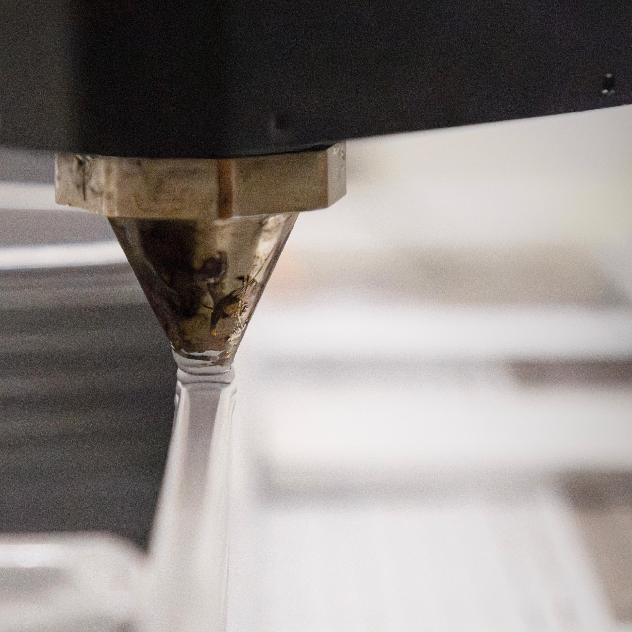
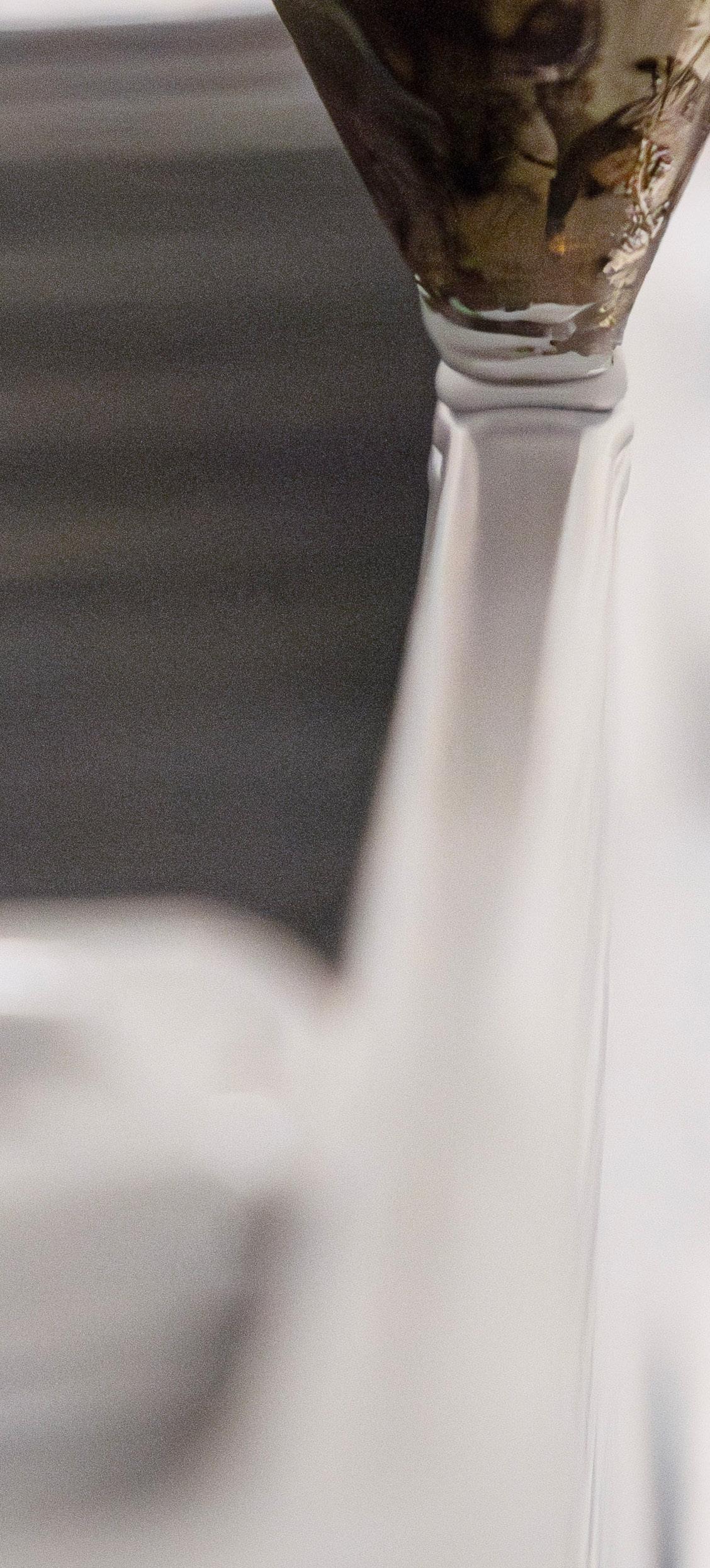
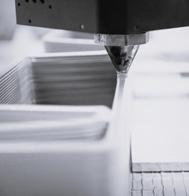
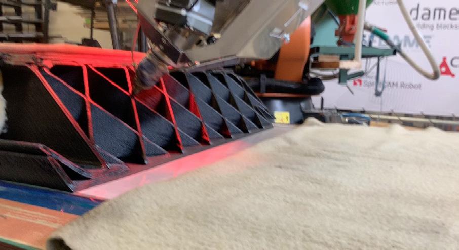
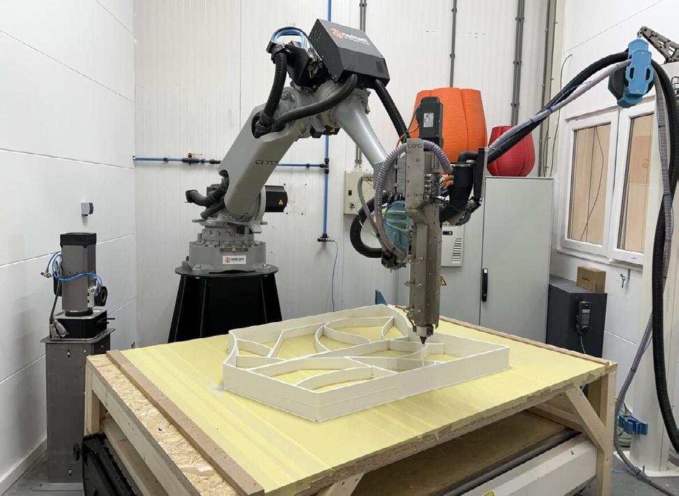
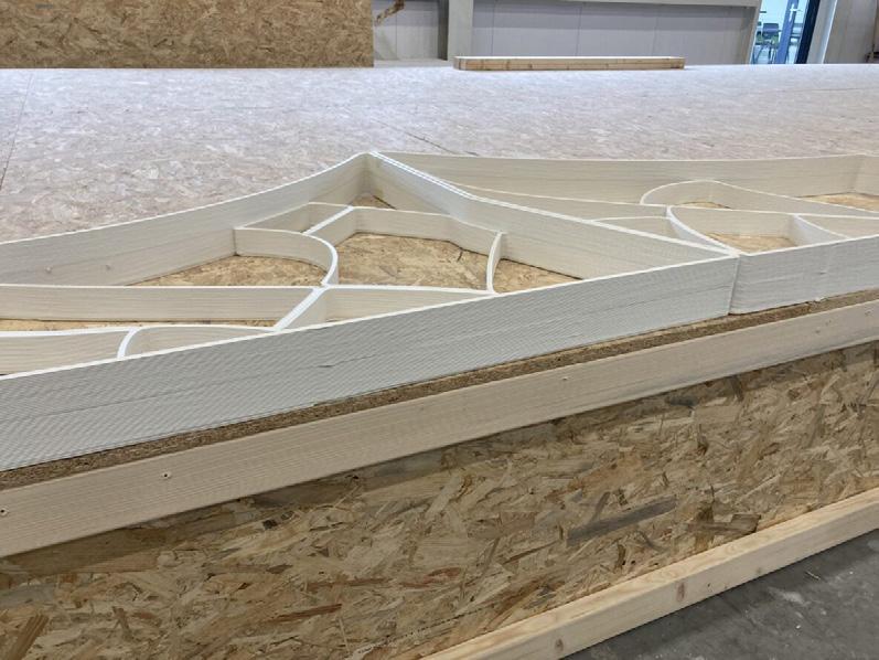
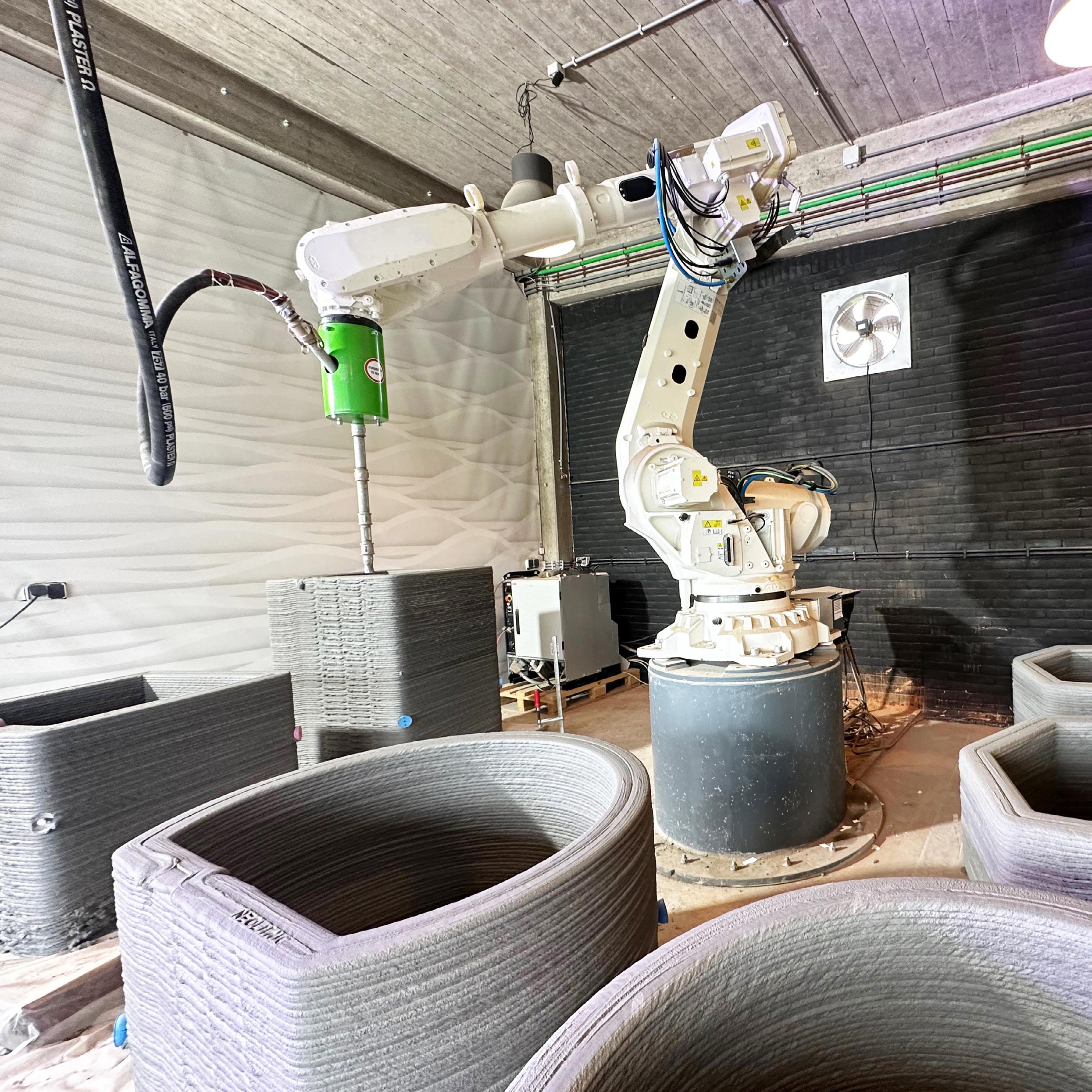
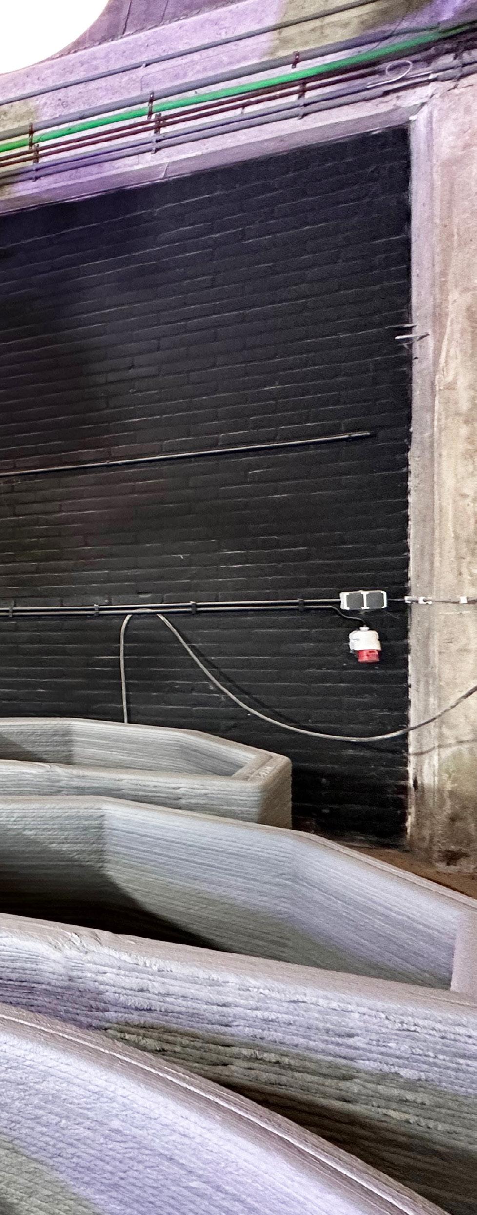
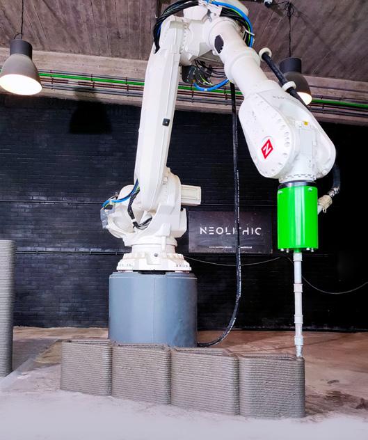
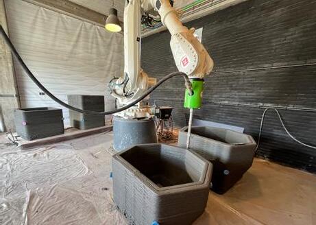
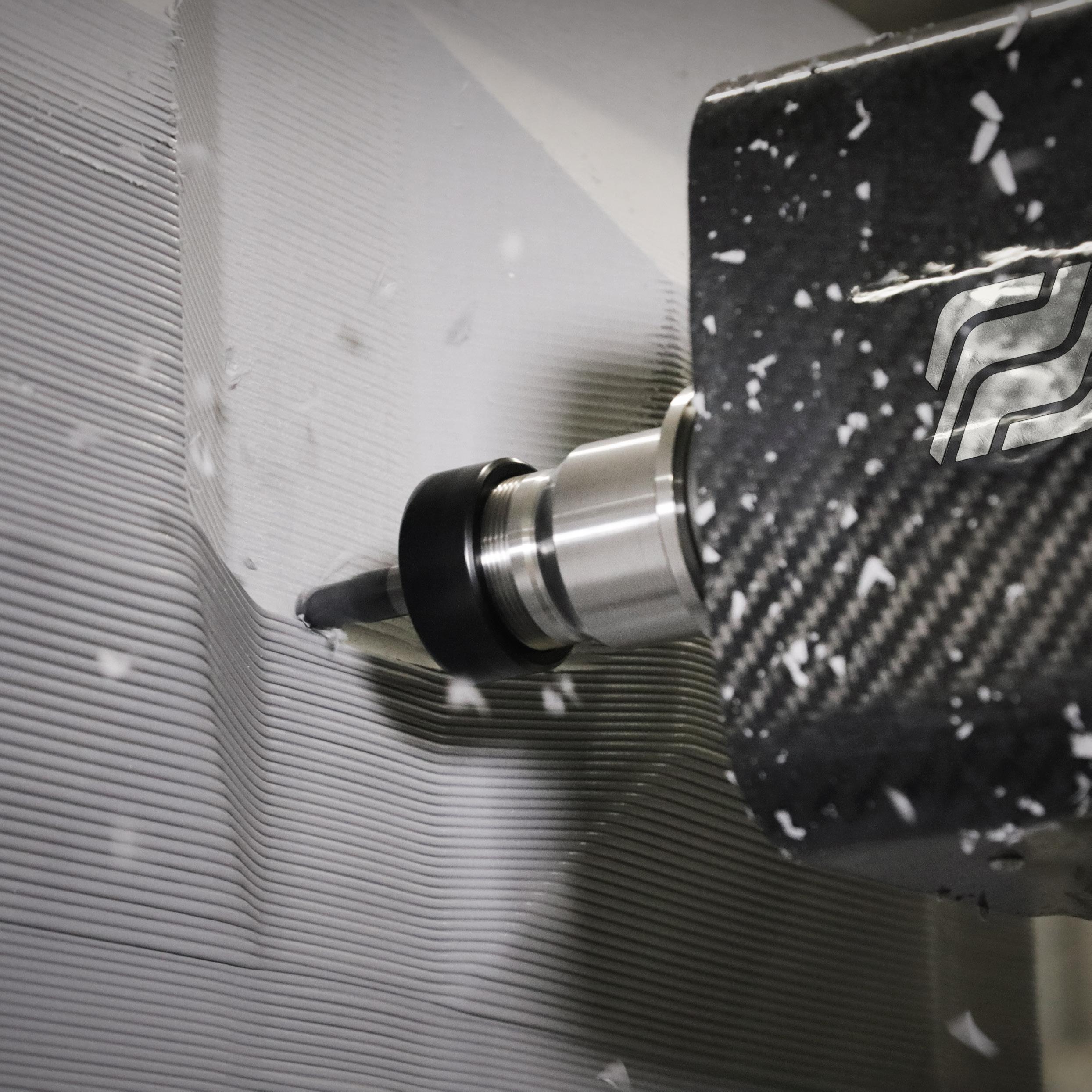
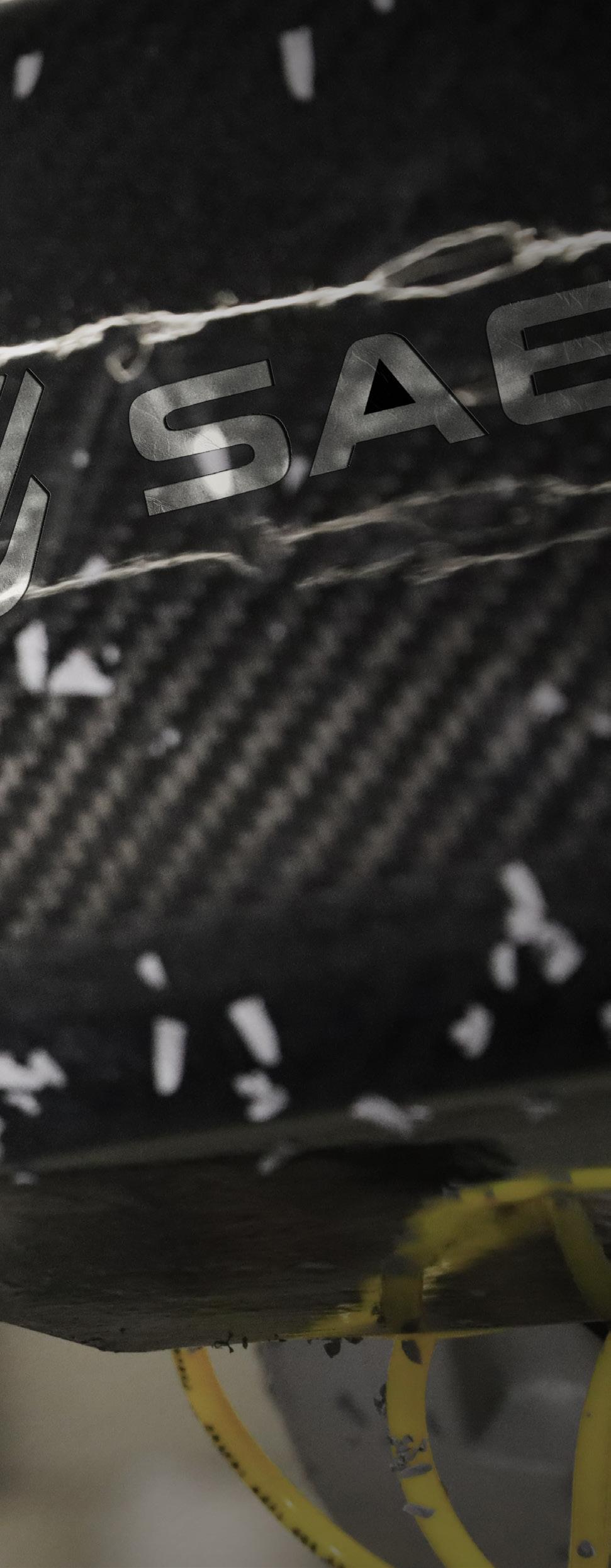
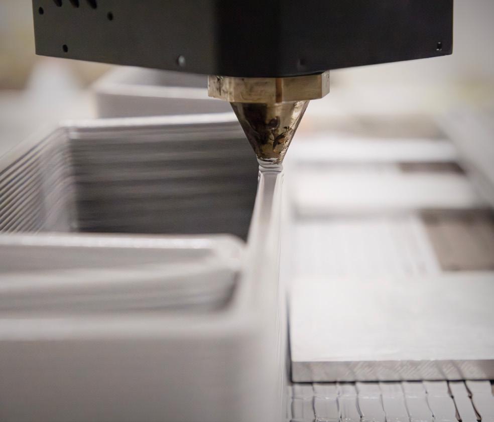
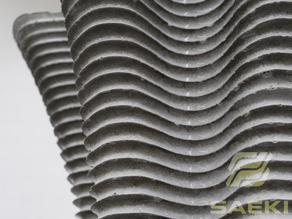
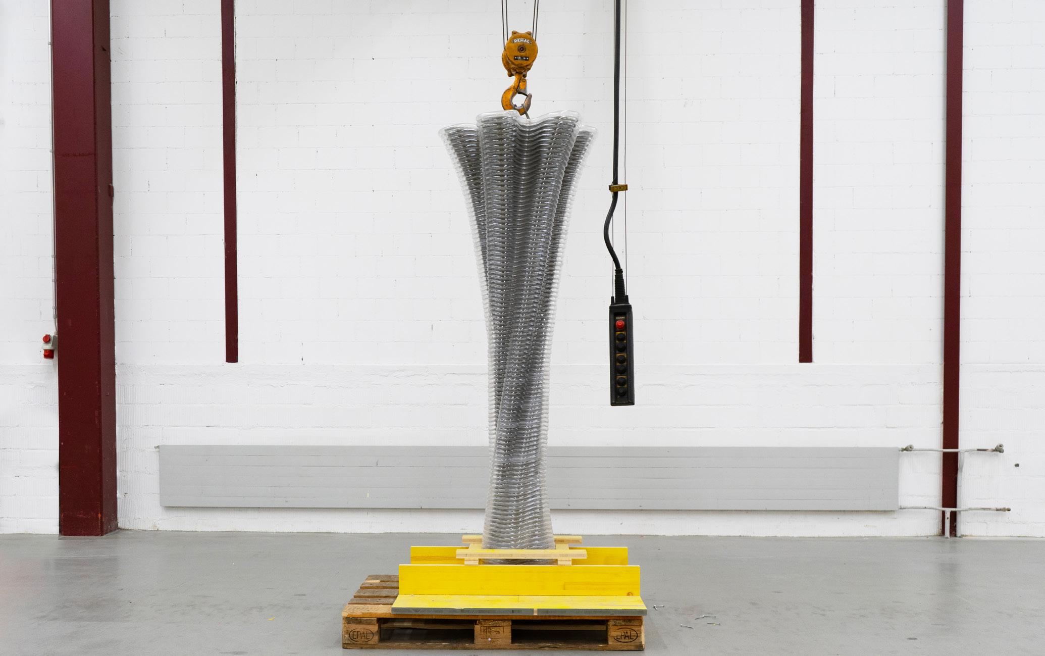
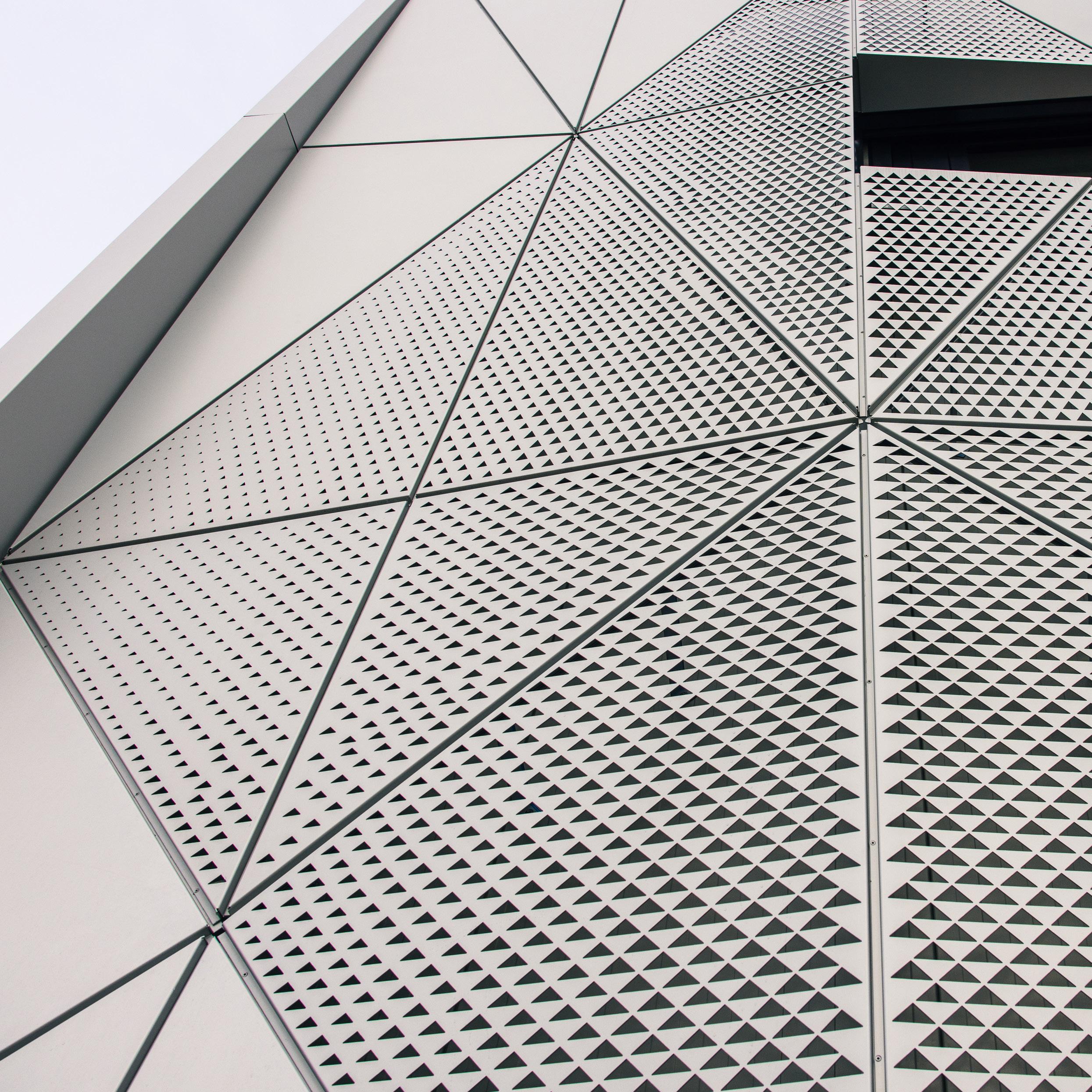
The cover image shows a robot by SAEKI producing a polymer 3D-printed formwork, to create a concrete waffled panel.
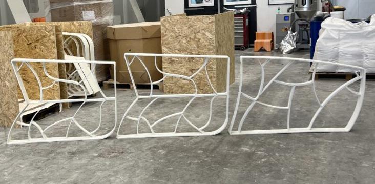
Saeki is a fast-growing digital fabrication startup based in Zurich. With their micro-factories, they deliver digitally manufactured large-scale polymer products for the construction industry and beyond. Unlike traditional techniques, a freeform shape can be achieved. Saeki’s robot builds the required formwork layer by layer from a digital model. After the print, the outside surface can be milled by the same robot, to achieve the desired textural surface.
@saekirobotics
https://www.saeki.ch/
RUMOER 84 - ADDITIVE MANUFACTURING
2nd Quarter 2024
29th year of publication
RuMoer
RuMoer is the primary publication of the student and practice association for Building Technology ‘Praktijkvereniging BouT’ at the TU Delft Faculty of Architecture and the Built Environment. BouT is an organisation run by students and focused on bringing students in contact with the latest developments in the field of Building Technology and with related companies.
Every edition is covering one topic related to Building technology. Different perspectives are shown while focussing on academic and graduation topics, companies, projects and interviews.
With the topic 'Additive Manufacturing', we are publishing our 84th edition.
The Rumoer Committee is open to all students. Are you a creative student that is eager to learn about the latest achievements of TU Delft and Building Technology industry?
Come join us at our weekly meeting or email us at rumoer@praktijkverenigingbout.nl
Circulation
The RuMoer appears 3 times a year, with more than 150 printed copies and digital copies made available to members through online distribution.
Membership
Amounts per academic year (subject to change):
€ 10,- Students
€ 30,- PhD Students and alumni
€ 30,- Academic Staff
Single copies
Available at Bouw Shop (BK) for :
€ 5,- Students
€10,- Academic Staff , PhD Students and alumni
Sponsors
Praktijkvereniging BouT is looking for sponsors. Sponsors make activities possible such as study trips, symposia, case studies, advertisements on RuMoer, lectures and much more.
For more info contact BouT: info@praktijkverenigingbout.nl
If you are interested in BouT's sponsor packages, send an e-mail to: finances@praktijkverenigingBouT.nl
Disclamer
The editors do not take any responsibility for the photos and texts that are displayed in the magazine. Images may not be used in other media without permission of the original owner. The editors reserve the right to shorten or refuse publication without prior notification.
The built environment - Prof. Dr.Ing Ulrich K naack TU Delft Academic Article
3D printing of recyclable composite material - Liesbeth Tromp & Carlita Vis
Royal HaskoningDHV
Breaking ground with Bamboo - Jasmine Wong
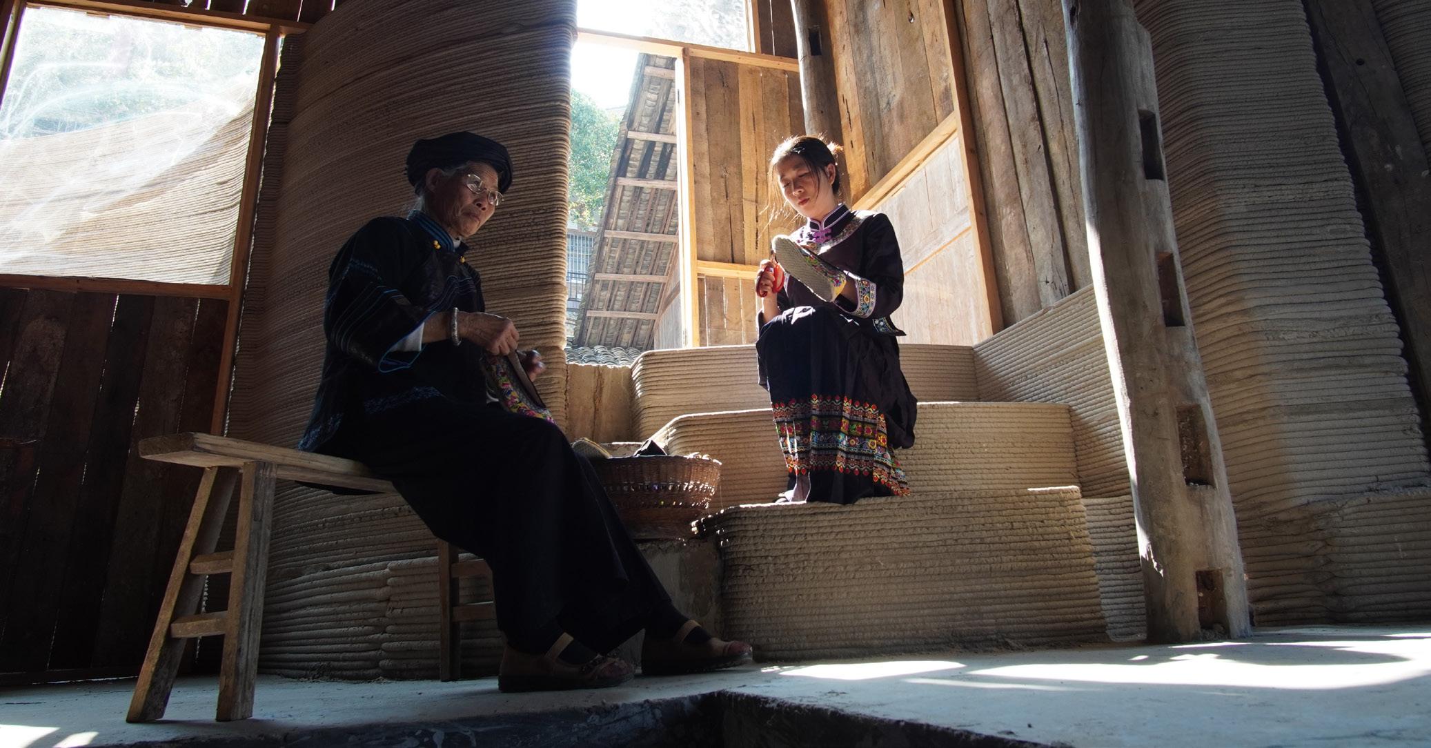
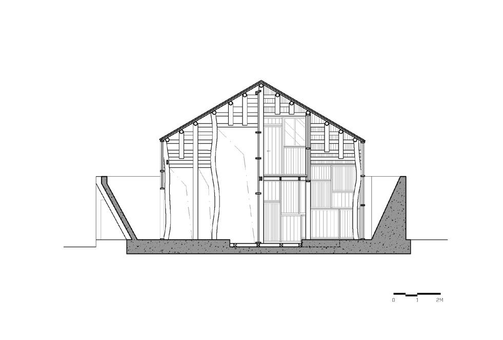
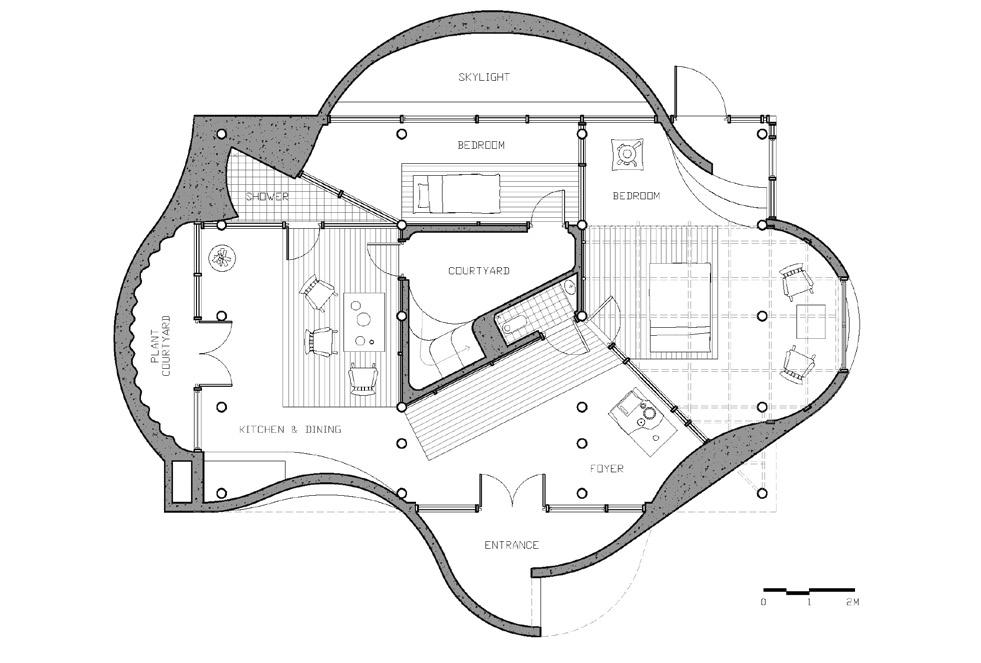
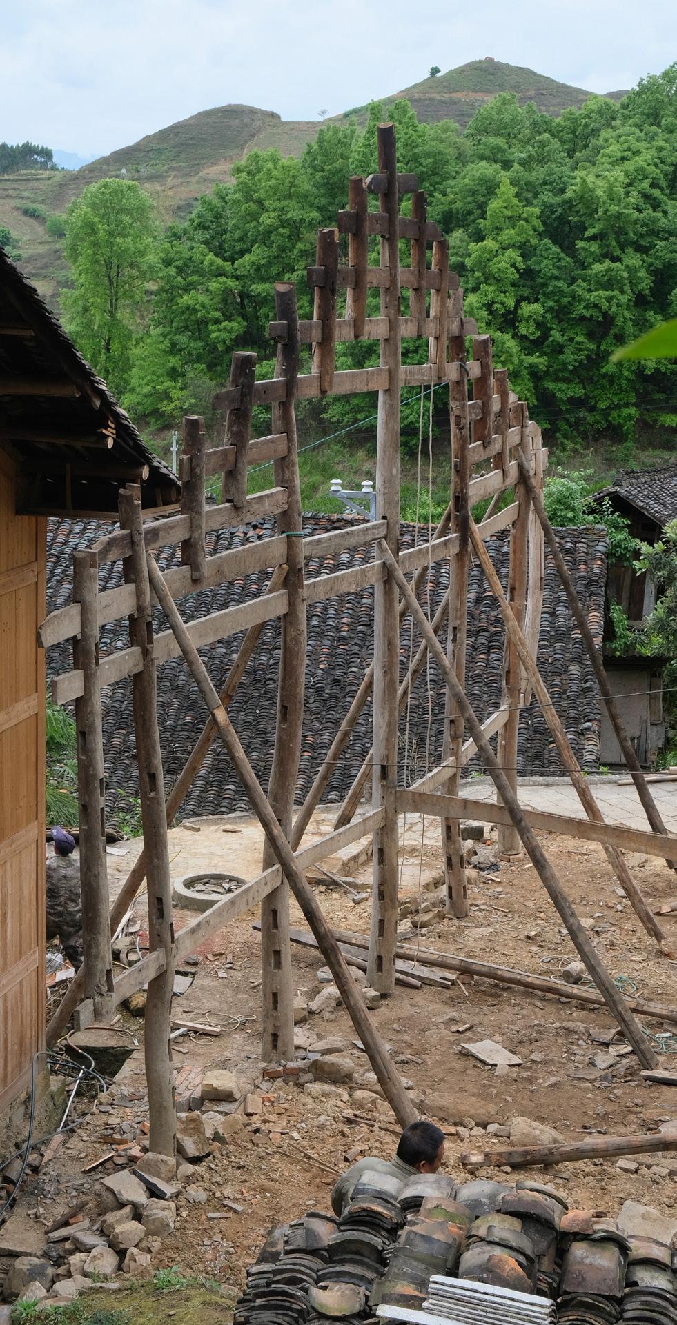
Traditional house of the future
Project article 62
- Lidia Ratoi, John Lin
The University of Hong K ong
Digital concrete production - Chris Aerts, Jeroen Veger
AM Envelope
- Dr. Holger Strauß, Innobuild GmbH
Study viss3 free form façade - Sebastian Thieme
Jansen AG
Saeki - Matthias Leschok
Rott-up - Ece Sel
MEGA project - TU Delft
BT Spotlight article
Buffering Oasis
BT Spotlight article 78
- Carmen Guchelaar
Extreme technology - TU Delft
Makers$Future
- Véronique van Minkelen
MEGA project - TU Delft
BT Spotlight article
Resilient rural housing
- K uba Wyszomirski
Extreme technology - TU Delft
BT Spotlight article
Debut 2024
- Ece Sel and Sander Bentvelsen
Praktijkvereniging Bout TU Delft
Bout Events and Trips - Praktijkvereniging Bout TU Delft
EDITORIAL
Dear reader,
It is with great pleasure that I present to you the 84th edition of RuMoer: Additive Manufacturing.
In the ever-evolving realm of technology, we witness continual advancements in the potential methods of constructing buildings. Innovative approaches such as Additive Manufacturing utilizing novel materials, empower architects and engineers to select construction methods tailor-made for their designs. This not only enriches architectural creativity but also contributes to enhanced building performance in areas like sustainability, structural efficiency, improved indoor climates, and the facilitation of true freeform architecture. In the 84th edition , we explore the integration of Additive Manufacturing, opening up a multitude of possibilities for refining architectural engineering in future designs.
With the previous issue,we introduced the BT Spotlight section in the periodical, showcasing the exceptional work of the Building Technology master track students. This initiative garnered overwhelming appreciation and recognition from companies and universities alike. With this edition, we are thrilled to showcase projects from the integrated design studios of the master track– the MEGA project and the Extreme technology. We hope these projects assist the aspiring students in making informed choices for elective courses and also inspire and inform readers about the Building Technology master track.
This edition also marks the expansion of the RuMoer committee. I would like to welcome the new members: Daniel, Rossella, Mauritz and Swornava to our growing team. Furthermore, I would like to acknowledge the dedicated members of the RuMoer committee who consistently work towards enhancing the quality of the periodical.
Conversation with Prof. Dr. Ing Ulrich Knaack at TU Delft
The Genesis of 3D printing in the Built Environment at TU Delft
For me, the whole thing started with Marcel Bilow, who asked me to help finance the first 3D printer at the University we were working at that time. And, after we managed to get the first plastic printer, Marcel directly developed the first objects to be printed during the Christmas break – impressive results back then. The device, which cost 100 times that of currently available plastic printers, had a volume of two cubic meters for a print space of 20 x 20 x 20 cm. This describes how the technology evolved over the last decades - not only in terms of available materials but also in terms of volume and costs.
A second story of the time: we talked to specialists in additive manufacturing and learned that printing for the built environment would not work due to the wrong materials and the industry’s attitude:
"
Printing aluminium will never work, physically impossibleyou are just crazy! "
Well, we now see that it is possible to print aluminium in various ways. And we see building products being printed.
Lesson learned: Do not always trust specialists; give it a try yourself!
The evolution of materials and applications in construction
We observe a wide variety of printing materials, including polymers/plastics in various printing technologies, mineral materials, and metals. Concrete printing— extruding fluid concrete with a robot-controlled extruder in defined geometries—remains a leading technology for the built environment. In research, this is significantly driven by places like Eindhoven, Braunschweig, München, and Copenhagen. We also witness the first industries adapting the technology and offering substantial construction dimensions to the market. The key challenge, after solving the geometry and material properties, is reinforcements. In this regard, the mentioned research environments are competing to find a solution for not only short-fiber metal but also proper reinforcement systems. Patents are pending, but we have yet to see practical applications
Advancements in metal printing
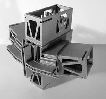
The next material field in use is metals. Utilizing laser sintering technology, highly complex stainless steel or aluminum components are developed. These components can be found in our built environment as complex geometry nodes for structures or facade systems. Some of our PhDs in Delft have made significant contributions to the development of these components, participating in product developments. Currently, we have about three available technical solutions: free-form stick systems with 3D printed nodes. This approach allows us to keep the main system simple and use conventional components by shifting the complexity to the 3D printed nodes.
In the next step, the same geometry concepts were applied to stainless steel solutions. Lia Tramontini is finishing an interesting PhD on this in Delft, in cooperation with an industry partner. She is transferring her work into a market-ready product. Additionally, she has introduced the possibility to print any free-form polymer gasket, which makes sense given the complexity of the loadbearing parts and the drainage needs of the facades.
Moving forward, Wire Arc Additive Manufacturing (WAAM) comes into play. We all remember the 3D-printed steel bridge in Amsterdam, which took a while to build and evaluate. It functioned as a pedestrian bridge for a while but is unfortunately now being deconstructed. What makes this technology suitable for our built environment is that we are accustomed to welding technology in the building industry. Welding is something we know, with the only difference being that it is now operated by a robot, making us feel comfortable with it. Of course, there is still a lot of research to be done to identify the best welding parameters, material performances, and the environmental impact of this technology. Nevertheless, we see a significant number of projects developing –not only bridges but also facade components, spider connectors, and free-form nodes for complex structures.
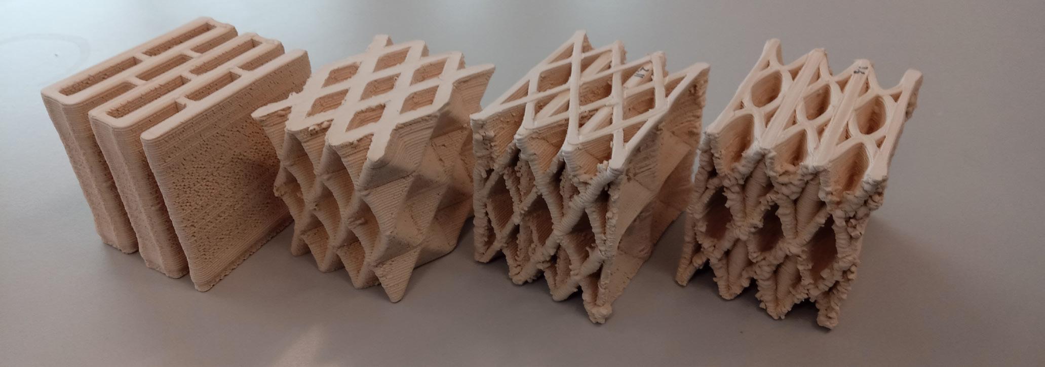
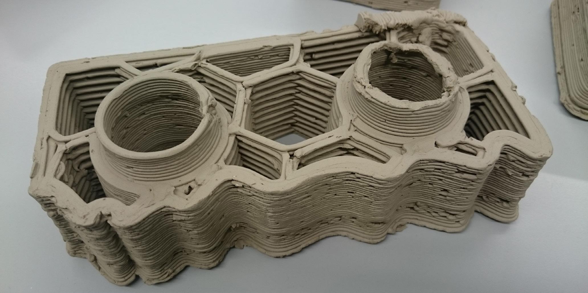
The next stop is ceramics! It employs a similar extrusion technology as for concrete but with a different curing process. This involves printing larger geometries for clay structures, such as entire buildings, or finely defined objects with thin extruded lines of clay. In a firing process,
these lines are transformed into ceramics. In Delft, we developed a sample redefining our blue tiles – now with complex geometries and patterns on the surface, glazed with pigments, and installed as facade cladding. Alongside this, in a parallel project, we are establishing components with additional functions.
Venturing into unconventional territories : Polymers, Timber and Glass
In the field of polymers, we observe the most profound developments in printing technologies, leading to a wide variety of opportunities in use: shading components, full wall systems integrating insulation, and the integration of fluids to control energy harvesting and transport in facades are concepts under development. However, we still encounter challenges with UV, fire, and durability –which is logical when considering the typical lifespan of buildings and building components.
Yet, we have learned not to halt our investigations when things get complicated in the initial steps. Michela Turrin and I have come across numerous MSc theses that develop interesting ideas – one of them involving the printing of timber! Here, we are referring to timber made of fibers and lignin with no additional adhesive. Solutions found in one thesis and application concepts developed in the next two are now awaiting the creation of the first serious building component. Concurrently, I am involved in a PhD thesis about printing paper as volumetric objects: a similar journey of making the material printable, identifying material performance, and finally, applying it.
Finally, the most complex material to print is glass. In this case, we are dealing with temperatures around 1000°C.
We need to develop a print environment that allows us to handle this temperature while still controlling the geometry. Thus, we see glass being cast into 3D-printed molds or glass ropes being heated and printed into volumes. Apart from creating the objects themselves, the complexity of printing on surfaces (glass plates) with all the thermal stresses poses a significant challenge
Consideration of 3D printing for construction
When contemplating this, we can identify numerous areas for future research on various topics. These include material performances, the application of printing technologies in our industry, and discussions about potential product applications, including warranties,
services, and distribution. However, limiting our consideration to printing materials solely for the purpose of replacing complex or otherwise impossible-tomake components does not do justice to the topic. The next field of interest should be exploring the potential for integrating additional functionality into building components—addressing structural, building-physical, and functional aspects.
Moreover, it's crucial to assess the actual environmental impact. While we often argue that less material is needed for a complex printed component, we lack a relevant estimation of the energy required for its manufacture. Simultaneously, we've learned that transport energy
constitutes a significant part of the environmental impact. In this regard, additive manufacturing with local production plans might present an opportunity for digitally-driven international engineering with local manufacturing—an intriguing concept for our building industry
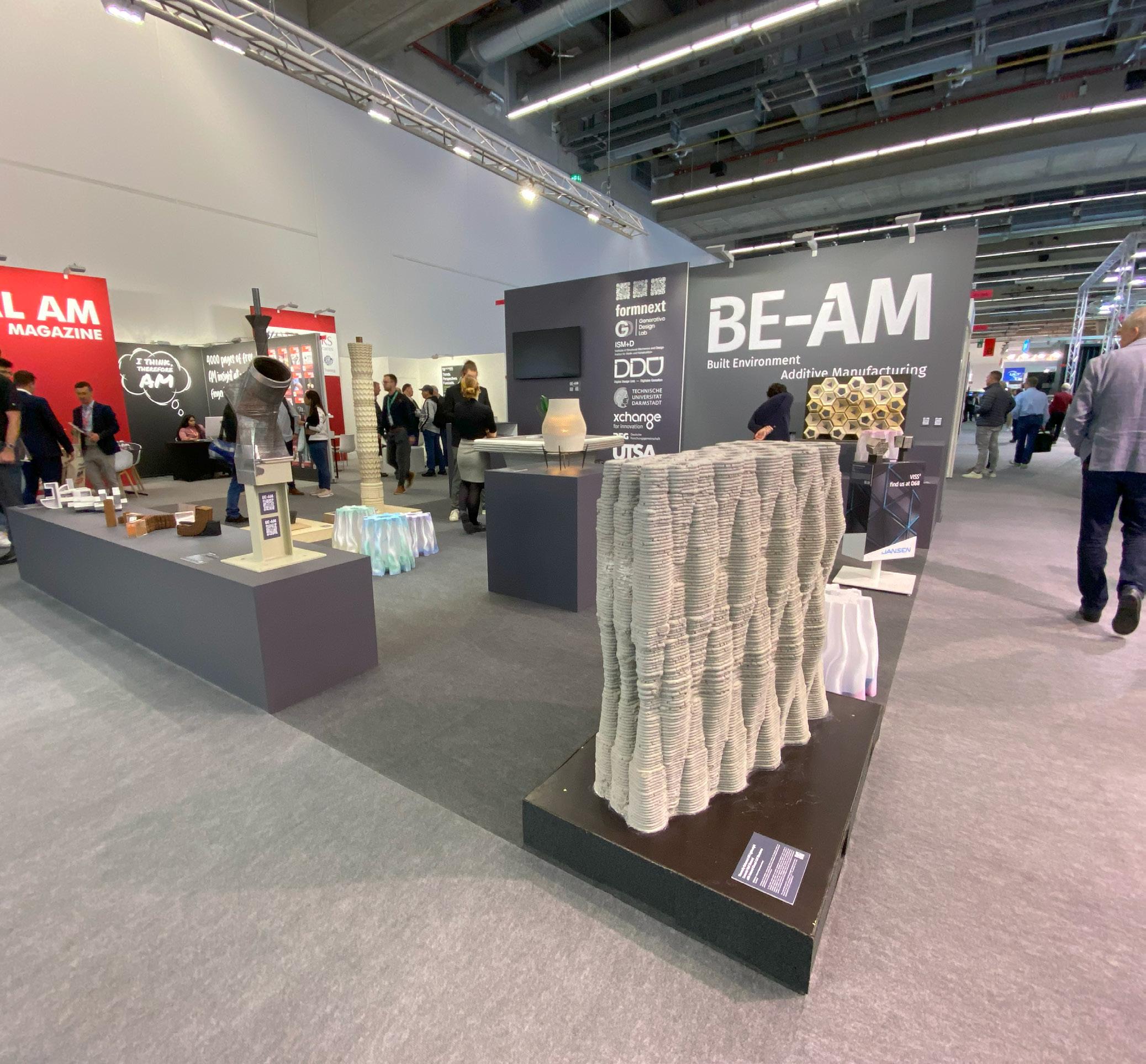
BE-AM Event : Showcasing the Future of Construction Technology
In closing, I'd like to share about an event. Please consider assessing our BE-AM event and exhibition, which takes place in November annually at the international trade show formNEXT in Frankfurt. Explore cutting-edge research and products in the realm of the built environment. Stay informed with our regularly updated webpage, featuring a map of active individuals in the field. Scan QR code on the introduction page to acces the webpage.
Prof. Knaack is a Professor of Design of Construction in the Department of Architectural Engineering + Technology. His expertise lies in the foundations of construction, materials, and joint applications. Research focuses on glass, facades, system construction, and organizational aspects. Notable contributions include work on economical doubleskin facades, integrated building installations, and facade systems for free-form, ICT-driven architecture. The chair emphasizes the integration of research and education, guiding students through practical applications of research results in largescale implementations.
Ulrich Knaack @bk.tudelft
3D PRINTING OF RECYCLABLE COMPOSITE MATERIAL
Liesbeth Tromp & Carlita Vis, Royal HaskoningDHV
As part of the digital workflow: applied innovation in infrastructure Workflows in infrastructure are becoming more and more digital with every project. Although every project is still unique, the workflows are similar. Standardisation and automation are more relevant than ever to create better and more sustainable designs. Robotised manufacturing and assembly will eventually seamlessly connect the digital design workflows with the production stage. And ultimately digital twins will then allow efficient life cycle management in the digital environment of the objects in the operational phase.
Royal HaskoningDHV (RHDHV) explores the emerging technologies to learn and contribute to developing effective and efficient digital workflows to realise our sustainability goals. How do we organise such workflows? How will this affect our ways of working, our responsibilities, and what skills need to be developed within project teams?
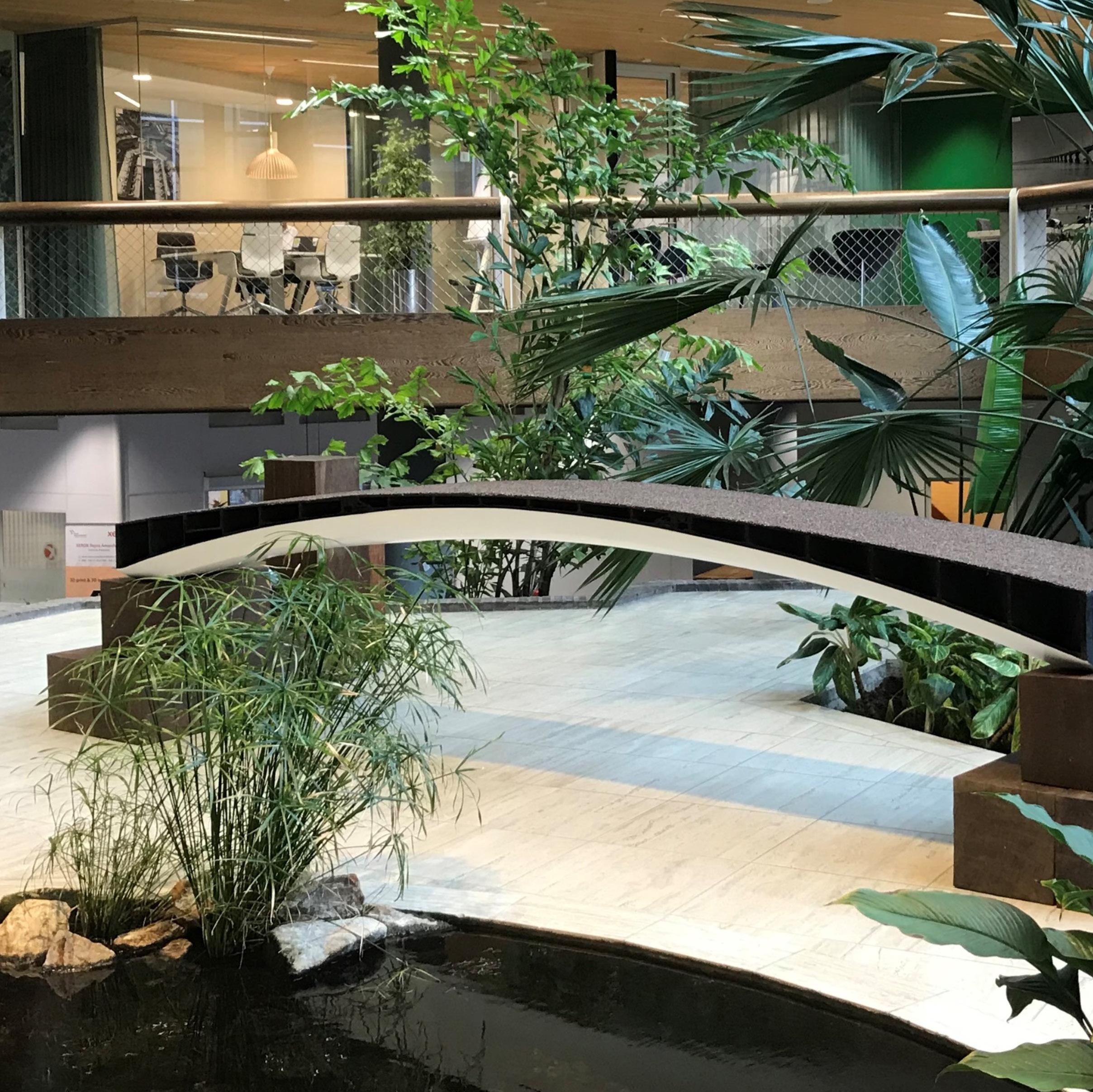
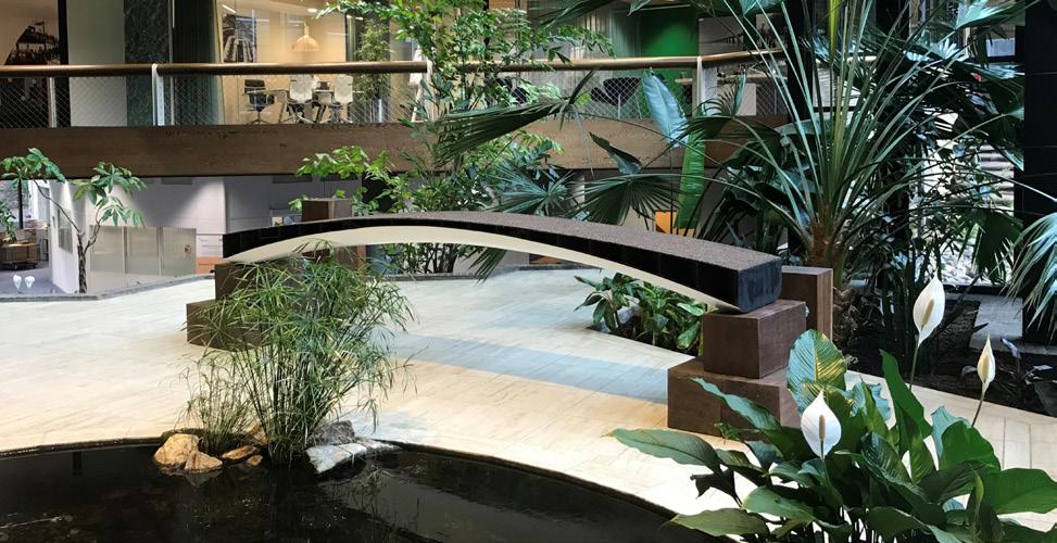
As a case study, RHDHV has investigated the potential of using 3D printing of recyclable composite materials for circularity and sustainability in the design and manufacturing of pedestrian bridges. 3D printing is a form of robotised additive manufacturing, in which the design and production are highly connected. Introducing new materials and technologies means that new players enter the infrastructure eco-system and responsibilities need to be relocated when material, design and production are so closely linked. This article discusses the impact and challenges the highly integrated Design for Additive Manufacturing (i.e 3D printing) has on the RHDHV project team and collaborations.
If we want to achieve our net-zero goals for 2050, we need to accelerate the process for development and implementation of innovative solutions. In this article we share our insights and lessons learned.
Our journey : Material
Our journey started with the ambition to create a 3D printed fully circular composite pedestrian bridge. The first step was the selection of the material. The main criterion for the material is circularity, but for the application in the bridge the material must be lightweight have high strength, high stiffness and suitable for outdoor
applications, i.e. moisture and temperature resistant as well as robust. The fire retardancy should be reasonable to high (anti-vandalism). UV resistance could be taken care of by a coating; however, the material itself should have some UV resistance as well. Materials such as nylons for example have a high enough thermal stability, but the mechanical properties are significantly reduced by moisture absorption. The selected material for this case study was a glass fibre reinforced thermoplastic polymer, PET, in this article also referred to as circular composite. The addition of short glass fibres (on average 0.3 mm length) increases stiffness and strength significantly.
The expected design life of the bridge is 50 – 100 years. Because of its low weight, the bridge as a whole can be easily relocated to fully make use of the design life. At the end-of-life, the bridge can be shredded, and the composite material can be upcycled and re-used for new, 3D printed high-end structures.
In several development steps (sprints) we learned by doing, creating larger and more complex demonstrators with each sprint. We went from a 1 m bridge to a 2 m bridge, a 4 m bridge, working towards a 6 m bridge.
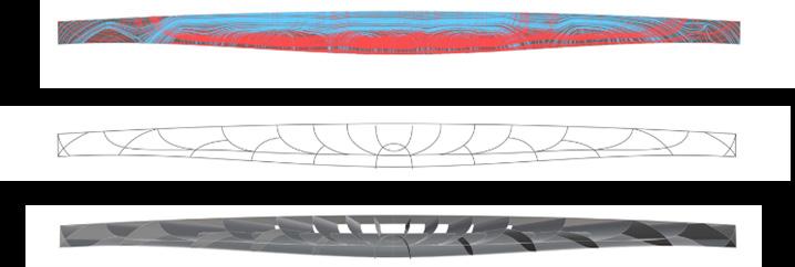
During the printing the material exits a very narrow nozzle, which causes the short fibres to align. The resulting material is very orthotropic, meaning much stiffer and stronger in print direction than the transverse direction. The structural design and geometry are aligned with these very characteristic material properties.
In the 1 m specimen we explored the principal stressconcept. Materials in general perform best when axially loaded rather than in bending, so choosing a structural geometry following the lines of principal stress implies a high degree of material efficiency.
A demonstrator specimen of 1 m span was printed and the design performed well structurally. However, we learned from this test that continuity and avoiding crossing print paths in the cross section are preferred to avoid smearing of the printed material. In addition, when considering strategies on how to further demonstrate the load bearing capacity and reliability of the structure, the complex infill of this concept introduces a lot of uncertainties. For future designs we decided to simplify the infill, making the structure less sensitive to different loading conditions and allowing for demonstration of the load bearing capacity based on a simple component test.
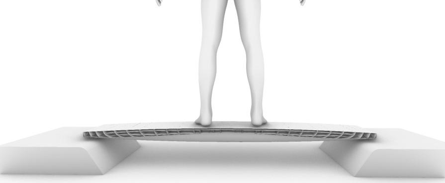
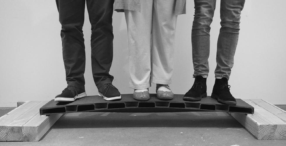
We optimised the cross section in our 2 m and 4 m span demonstrators. We varied the infill, but in all concepts, we aligned the printing direction of the top and bottom skin of the deck in the spanwise direction, aligning maximum strength and stiffness of the material with the highest loads.
The main challenge when increasing the scale of the structure turned out to be the thermal management of the printing process. An important design parameter for 3D printing of circular composites is the layer time, i.e the time frame in which the extruder passes the same location to deposit the next layer. To obtain a good layer-to-layer bond, the receiving layer may not cool below a certain temperature.
The longer the print path in a cross section, and the more complex the geometry (i.e. changes in direction), the longer the resulting layer time. Because pedestrian bridges need to be able to resist highly localised loads, the infill that supports the top skin to carry the traffic loads and point loads as prescribed in the design codes needs to be rather finely distributed, resulting in long print paths per cross section.
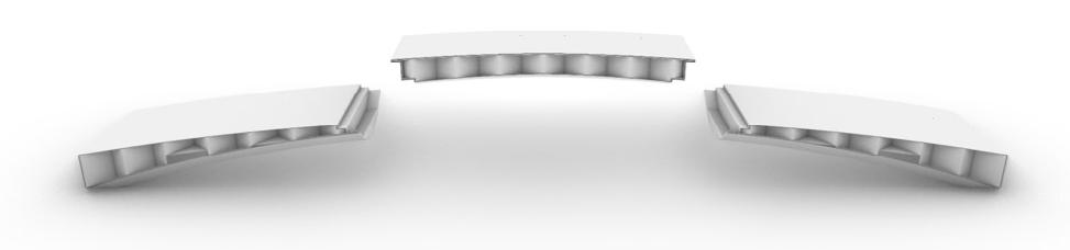
In future the layer time restraint might be resolved for example by advanced thermal management or investments in printing equipment, but at the time, in our prototyping phase, we were limited in our options. To reduce the layer time, we were forced to build our
structure out of several smaller elements.
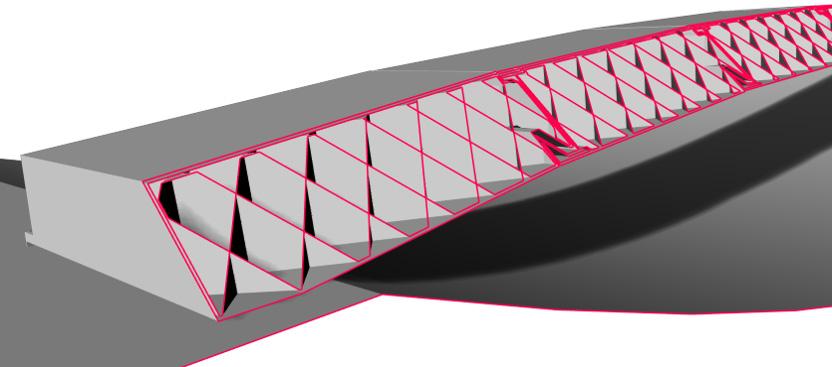
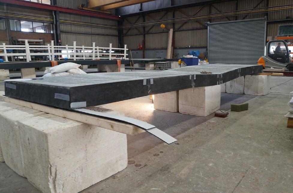
To maintain a print path within the allowable layer timeframe while aligning the fibers partly to the main loading direction, the print plane can be rotated in the horizontal plane (45 degrees in top view, like herringbone pattern) or vertical plane (reclining for example under 45 degree). But even with these compromises, due to the local load requirement, we were not able to achieve the required deck dimensions and infill geometry without spanwise segmentation. For the spanwise connection a hybrid adhesive/mechanically interlocking system was developed. The resulting geometry for the 6 m bridge had 0-degree rotation in the top view and a 45-degree rotation in the vertical plane, see Figure 4.
To reduce the risks of damage of the top skin under localised loads and to strengthen the structure and the connections, it was decided to apply a thin 3 mm continuous glass fibre reinforced layer on the top skin as reinforcement.
The reinforcement layer and segmentation are undesirable in a digital workflow, because it introduces
assembly, and some preprocessing. All print paths must be connected. Therefore the resulting complex geometry, the connections and the assembly involved introduce high geometric requirements, i.e. low production tolerances.
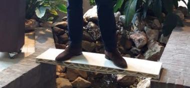
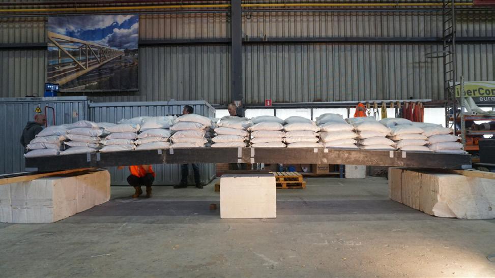
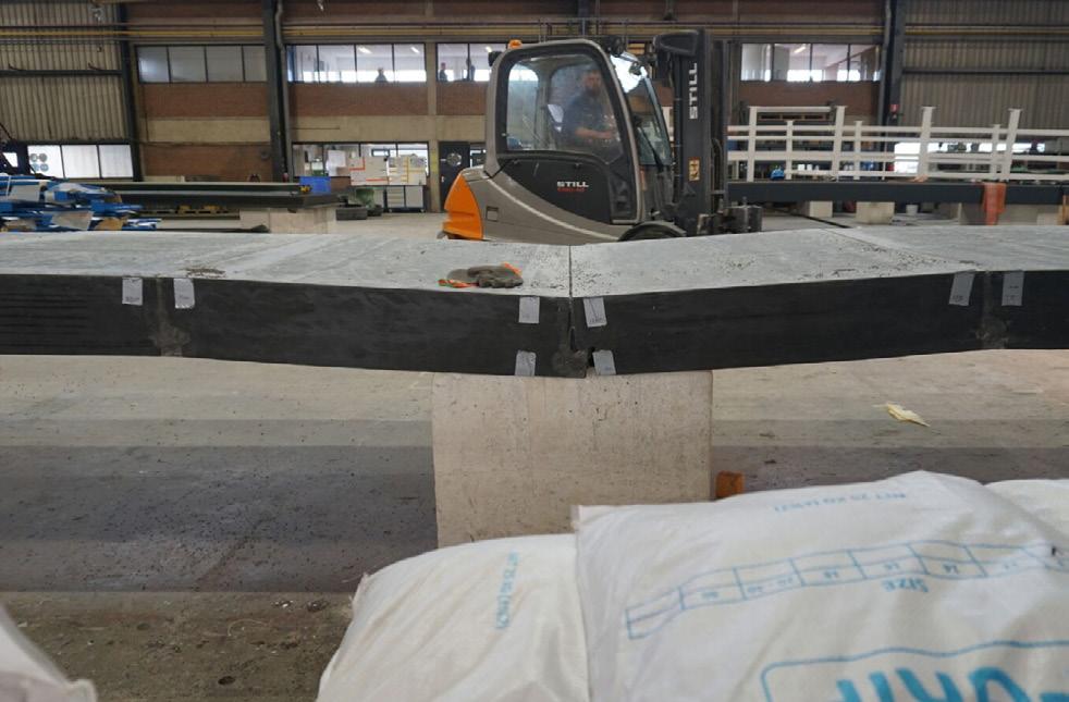
A full-scale test was performed where the bridge was loaded with the full distributed load of 5 kN/m2, with an additional factor of 1.2, to take into account some material uncertainties, see Figure 5. The initial response of the bridge was as expected, with slightly higher deflections (+ 10%) which can be explained by the connections.
& 8:
Unfortunately, the bridge was only able to sustain the load for no longer than approximately 30 minutes. After some sustained loading with its maximum test load of 6 kN/m2 the bridge failed at one of the connections.
Detailed inspection after the test exposed that during the printing not all print paths had connected, greatly affecting the structural capacity. This possibly also contributed to the 10% higher deflections that were measured. Even when a small number of required connections are missed, such local defect is unacceptable.
Future needs
This case study was an exciting journey which showed learning by doing generates numerous insights in just a few development steps. The main conclusion is that demanding applications and complex geometries such as required for large scale 3D printed structural applications, such as the pedestrian bridge as presented here, require accurate manufacturing and high quality control. Furthermore, it could also be the case that thermal
stresses that were locked in during the manufacturing contributed to the lower load bearing capacity. The glass fibre reinforced PET material that was used, though very strong and stiff, also means that higher thermal stresses get locked in during the printing and subsequent cooling down, where a softer material such as PETG might be more forgiving. Developments with continuous fibre reinforced thermoplastic tapes could also provide interesting options for optimizing the structure. Further research in this field is needed to be able to derive appropriate materials and the associated production settings and design limits.
The future for 3D printing in infrastructure is very positive, driven by the need for circular, sustainable solutions. The technology is rapidly maturing and new material formulations, printing and integrated datalogging systems are put on the market since then.
Changes in responsibilities and value chain
Traditional construction involves a linear process with various moments to reflect, check and adapt during design and construction stages. Different materials, equipment and skillsets are involved in various project stages. Information is transferred from the engineer to the contractor to the people in the production facilities or at the site. Structural Additive Manufacturing is a more continuous and direct process. From the overall geometric layout up to the tiniest detail, everything is the result of a single source of code fed directly from the engineer’s design to the robot, preferably printed in one go.
Material and processing skill sets have been translated into design values and printing process parameters. The main question is at what stage of the design is the
choice for material and print strategy made, as they are so fundamentally part of all design choices?
Because of the direct transfer of information, drawings are replaced by digital models and codes, transferred without further detailed instructions, as (ideally) all instructions are captured in the codes. If it is preferred to create reference designs, for decision making upon investments by asset owners and with which consortia of contractors can tender, then tools need to be developed to incorporate printer settings and material properties and translate these (through preferably automated and calibrated computational coding) into the final geometry as well as printer settings (G-code).
In traditional processes the contractor is responsible for construction and makes the necessary, usually small, adaptations in the final design stage. The designerengineer role is not solely creating structurally feasible designs but also coming up with a matching printing strategy that fit the printer settings of materials and extruders. As the design goes directly to the 3D printer, the contractor-manufacturer needs to be involved early in the design process, to make sure the design is easy to produce and assemble and is in line with the installation strategy. Therefore, the manufacturing, assembly and installation strategy are more fundamentally embedded in the structural design. Hence the liability shifts towards designer and engineer and roles merge.
Circularity is more thoroughly embedded in the value chain responsibilities, adding recycling companies to the eco-system. How will we control the time delay between construction and end-of-life? How can we keep track
of the quality of the recycled (mixed) materials whilst making optimum use of the quality of the material, rather than making conservative assumptions or more frequently upcycling of materials, which increases the footprint? These are important questions that still need to be resolved.
Digital twins and life cycle management
Circularity means closing the loop: looking into the whole life cycle and not only the production phase. The performance of the asset and the ‘embedded value’ of the material need to be known. Sensor techniques can be fairly easily applied to establish a digital twin which can give the asset manager the necessary information. This ranges from basic information such as usage of the bridge and environmental data, to more operation-based data such as the relation between temperature, deflection and stresses. A digital twin predicts the residual lifetime based on usage and external influences and warns the asset manager in case of excessive use. This automated process potentially leads to targeted inspections only.
Conclusions
What we took from our journey is that it confirmed the high potential of digital workflows and 3D printing for infrastructure. It can save time and effort and creates an interesting new distribution of responsibilities. We learned that there is indeed a large degree of freedom in form, however other aspects involved in the design, such as automation, modularity, quality control, may favour more standardised geometries.
We need to especially much better understand all production settings to translate into design rules for
Additive Manufacturing. To be able to scale up, we need to know the thermal effects in the production stage, as well as manage the thermal state of the material during production. Preferably technological solutions become available where the design becomes independent of the printing layer time.
To reduce the amount of testing and physical demonstration of performance of a structure, data logging and fully integrated and automated quality control are important requirements to achieve an optimal digital workflow for circular composites. In other industries we see great examples of optimizing these processes with artificial intelligence.
In theory 3D printing of circular composite pedestrian bridges can be achieved in a near full digital workflow. Through scripting the different interfaces for data transference can be generated. On the short term however full circularity in a single component bridge as
part of a fully digital workflow seems not yet feasible. Further development is needed to get to the scale of economically viable circular products as bridges but large scale Additive Manufacturing is ever progressing and improvements in materials and equipment are rapidly put on the market.
In the meantime further experience in Design for Additive Manufacturing, production settings and tolerance control is gained working on smaller components such as the decks (under construction) and architectural handrail for a small circular bridge in Putten (the Netherlands), see Figure 10 and Figure 11.
Digital workflows can and will fundamentally change the role of an engineer in the construction industry. For decades, engineers have been responsible for creating designs and specifications for individual projects: each design optimised to meet the projects unique requirements.
Automated processes result in more standardised modular designs that can be applied in a large set of construction projects. Responsibility and liability in automated construction shift to the designers and engineers, since they are in control of design outcomes. As the industry shifts to a more product-based approach, the challenge for engineering and architecture firms will be to reskill their workforces and hire the right talent to design in this new setting.
Appeal
To achieve our net-zero goals for 2050, we need to develop new low emission solutions and implement them faster than we were used to. Applied innovation such as this case study are an effective way to verify the potential of concepts or emerging technology and identify missing links in a relatively short time frame. Even if the 6 m test did not fulfill the structural test it clearly demonstrated the items that need further improvement and some of the main challenges, giving direction to further developments.
In the traditional way of working, we have been trained to become risk averse, and therefore avoid the unknown. However, to contribute to the transition towards sustainable solutions we need partners and clients who are open for innovations and become part of the development team. The unknown has risks, but also holds potential solutions. It is up to us to apply our (engineering) skills and develop focused, step-by-step approaches to tackle the unknows, develop and demonstrate suitability and reliability of new solutions.
We try, we may fail, we learn, we improve, we share. This article is both a technical essay on lessons learned as well as an appeal to all people involved in (infrastructure) projects to step up and contribute to progress, develop and share knowledge and solutions, collaborating towards a circular, low emissions infrastructure.
Liesbeth Tromp
@Royal HaskoningDHV
Carlita is Innovations & Technical Director of Mobility & Infrastructure. She has project and management experience with clients and contractors in the infrastructure sector. Her motto is 'just do it' to start exploring new possibilities that enhance society together.
@Royal HaskoningDHV
Liesbeth is a FRP Lead Engineer with a passion for innovation. As senior structural engineer she specialized in innovative materials like FRP (Fiber Reinforced Polymers) and Design for Sustainability.
Liesbeth and Carlita both work at our businessline Mobility & Infrastructure in the Netherlands at Royal HaskoningDHV. Royal HaskoningDHV is a leading global consulting engineering company leveraging cutting-edge technology and software. Our multidisciplinary approach empowers clients with innovative and sustainable solutions, shaping the future.
Carlita Vis
BREAKING GROUND WITH BAMBOO
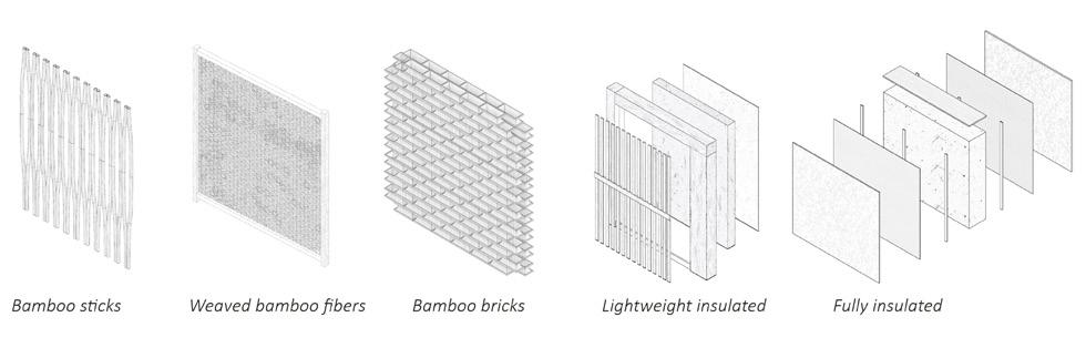
Robotic Additive Manufacturing of a Self Supporting Wall with Bamboo
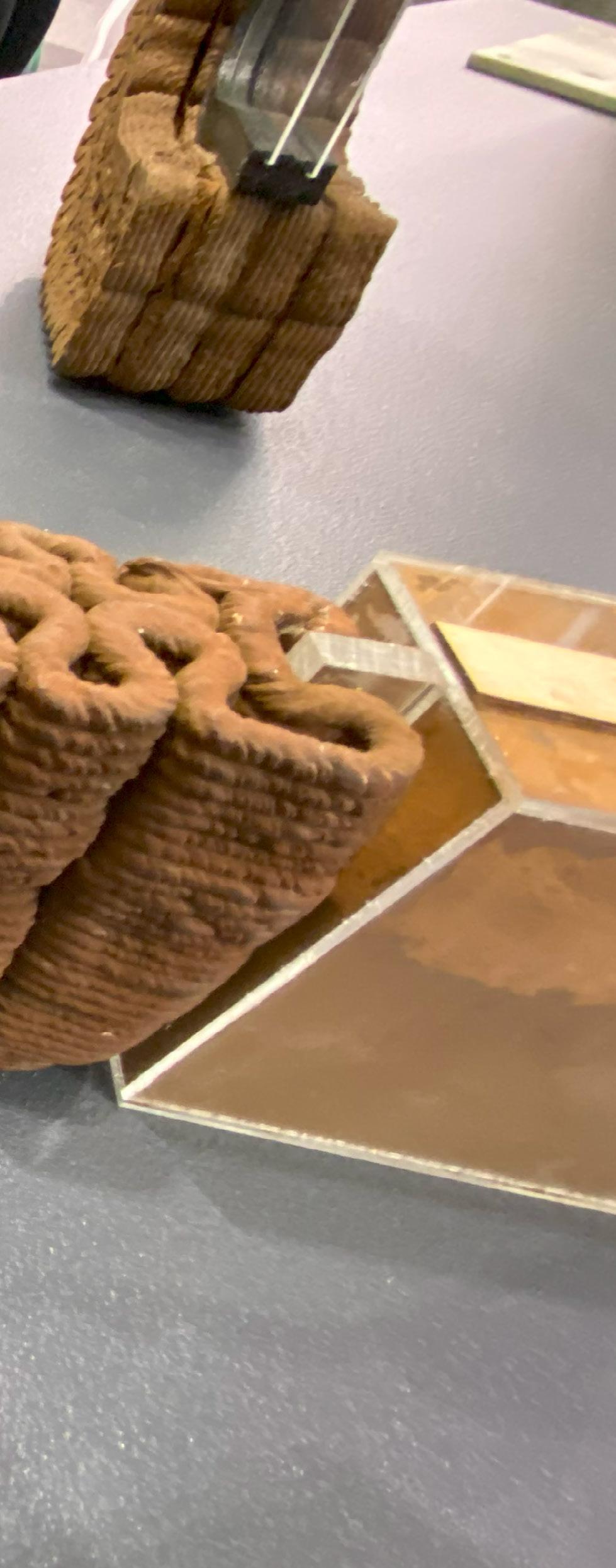
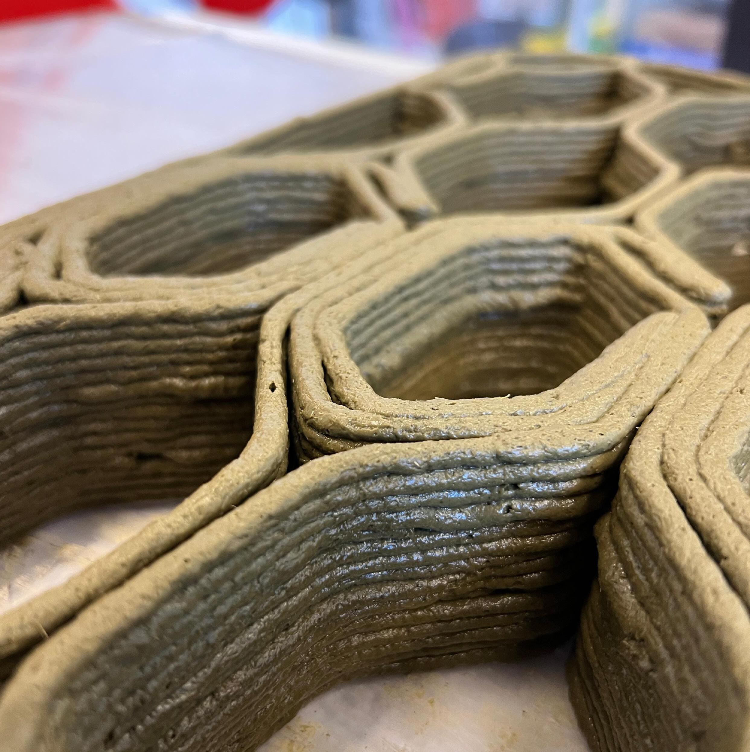
This master thesis explores the use of bamboo in Additive Manufacturing (AM), specifically towards the development of a building component. The presented study utilizes bamboo in the form of dust and fibers, which can be sourced from waste streams. This innovative approach not only offers a solution to the challenges of bamboo’s anatomy but also has the potential to use bamboo in a more circular way. With this approach, rather than being discarded at the end of its life cycle, bamboo products can be recycled and transformed into valuable powder and fibers, granting them a second life.
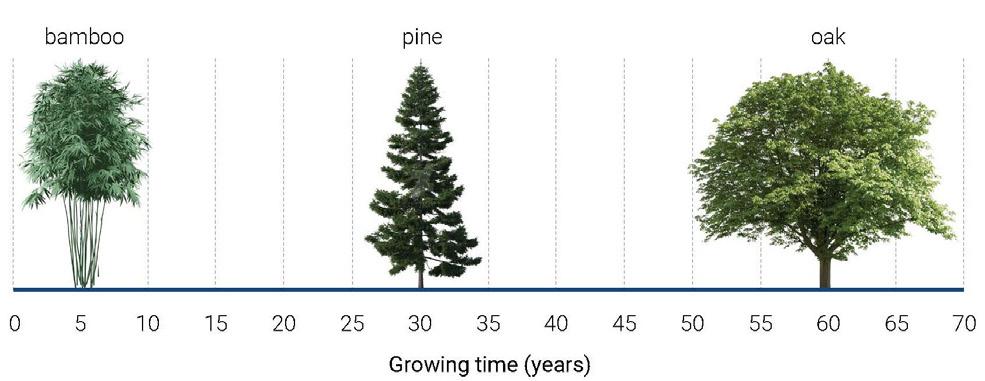
By leveraging the benefits of additive manufacturing technology, such as reduced material waste and the ability to fabricate complex geometries, the design aimed to create a mechanically informed infill tailored to the loading condition of the building component. After use, the component can be re-introduced into a new mixture to be used in a new AM application, enabling circular use. The project involves a comprehensive workflow, including material research, design development exploration, manufacturing process exploration and prototyping. The rapid population growth contributes to a considerable increase of the amount of raw materials used and produced worldwide (Craveiro, 2014). The aim to create more ecologically friendly and sustainable construction processes has boosted interest in the use of bio-based materials. Timber, for instance, has been a prominent choice, but its availability is constrained as the demand should not exceeds responsible forestry. Bamboo, a nonwood species, holds promise as a potential substitute to wood due to its rapid growth rate. It is a very adaptable plant that can grow well in a variety of climates and elevations, which enables it to contribute to the alleviation of demand for wood as a source of raw materials (Borowski, 2022).
(kampinga et al., 2015).
Materials
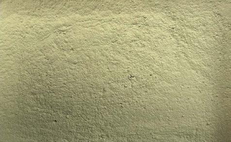
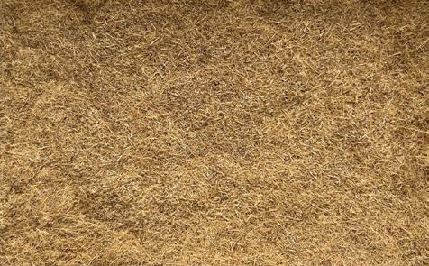
The raw materials employed in this research were primarily bamboo fibers and dust (Fig. 3).
Bamboo is a viscoelastic and anisotropic material that exhibits differences in physical and mechanical properties along its three orthogonal axes, with variations being more significant along the length of the culm due to the tapered shape and increasing density with height (Correal, 2020).
Bamboo presents impressive versatility, with the potential for nearly 100% material utilization in most cases.
In the construction industry, bamboo can serve as a viable replacement for traditional building materials across several components, including trusses, roof structures, walls, flooring, foundations, and scaffolding (Yadav, 2021). Still its adoption in this industry remains limited due to the challenges posed by its hollow tube anatomy and the lack of established building codes for its use. Furthermore, bamboo's physical and mechanical qualities are affected by moisture content, age, and the location on the stem (Correal, 2020).
Material Experimentation
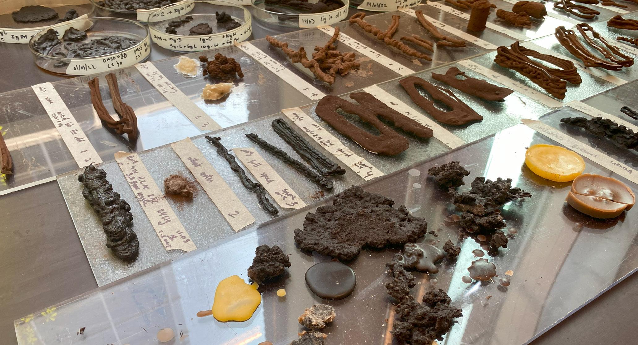
With the goal of formulating a fully bio-based recipe, a series of experiments was conducted to study the
Fig. 2: Bamboo, Pine tree and Oak tree growing time
behavior of various bio-based binders, both individually and combined in different ratios.
The material experiments aimed to comprehend the behaviour of bamboo dust and fibers when combined with various binders and solvents, with the objective of creating a stable bio-based composite with optimum viscosity and bonding properties suitable for extrusion via LDM technique. This exploration was carried out in two phases.
In the first phase of the material experiments, the focus was on exploring the binding agents that could be used to develop an extrudable paste. Initially, water was used as a binder to test the extrudability of bamboo dust. Therefore, different bio-based and non-bio-based binders were explored as potential alternatives.
After the initial phase of material experimentation, it was determined that a second phase was necessary in order to achieve a more comprehensive evaluation of the mix and
to refine key parameters for optimal printability in regard to the AM setup.
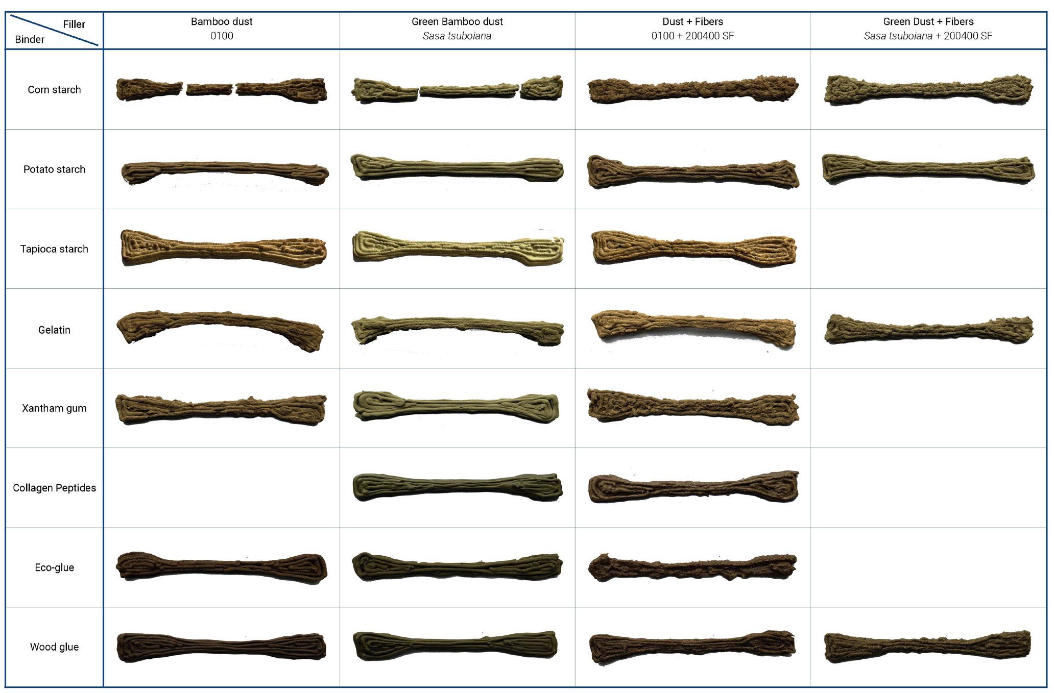
During the second phase, each binder was exclusively mixed with bamboo dust, as well as bamboo dust combined with fibers, to facilitate an effective comparison process. The results (Fig. 6) indicate the presence of some specimens that broke or bent during the drying process, categorizing them as faulty.
The optimal three mixtures, that included the use of potato starch, COLLALL eco-glue and wood glue as binders, were chosen based on a simplified mechanical test and other factors such as printability, cost, and bio-based content. The testing process revealed an interesting correlation between potato starch and eco-glue, as the latter is derived from potato starch. To ensure an effective and efficient testing process, only one binder was chosen for the initial printing test. Consequently, potato starch and eco glue were selected, with potato starch being the more cost-effective option.
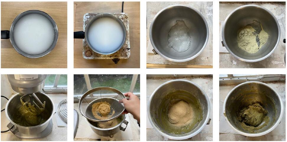
The selected mixture is subsequently manufactured in large quantities for the following AM application. This formed the basis for the next phase of the research, which focused on creating an extrudable and printable paste for the AM of a self-supporting wall made from bamboo dust and fibers.
Material Experimentation
A large quantity of the selected mixture made with bamboo dust and fibers and potato starch, needed to be produced in order to proceed with the printability test to explore the potential of the selected mixture through AM.
Design
The initial concept for this research was to demonstrate the potential of the novel material and fabrication technique. Therefore, the design had to be carefully considered to incorporate the capabilities of the selected mixture and AM technology.
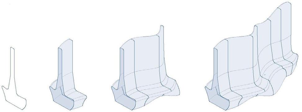
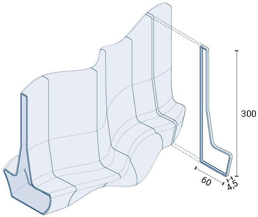
The aim is to create a mechanically informed infill that is tailored to the loads on specific parts of the building component. The design process began through a computational model by lofting different sections of a partition wall and benches on both sides (Fig. 6).
The design was heavily influenced by the novelty of the material and the fabrication process, to allow for a more efficient production process, the study focused on a specific section of the overall design (Fig. 7).
AM enables the realization of complex designs, not only in terms of visual aesthetics but also in terms of performance. Through the use of computational design and performance analysis, the material distribution of the component can be optimized within a specified space, considering loads and boundary conditions. This optimization process involves iteratively refining the material distribution.
To optimize the use of material and create a mechanically efficient infill, it is important to consider that the load on the component is not uniformly distributed. Therefore, it is unnecessary to have the same density in the entire geometry. It is a more efficient approach to create an infill that is mechanically informed and tailored to the loads on
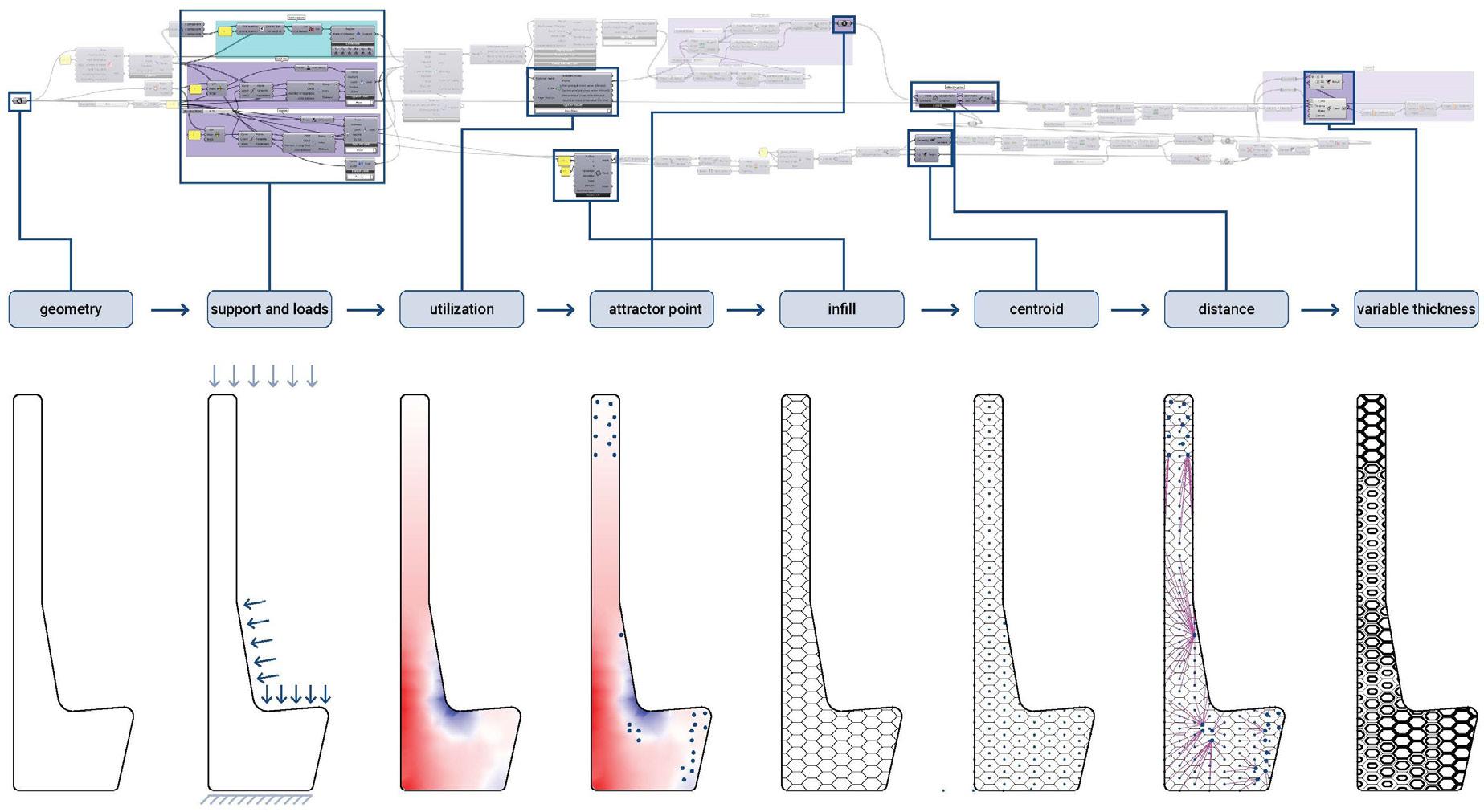
specific parts of the component. Figure 8 shows the computational workflow for the mechanically informed infill generation. A structural analysis determines the optimal density distribution within the infill. This analysis involves mapping the density of the infill based on the variable cell size and arrangement. The goal is to identify areas that require higher density to withstand greater loads, as well as regions where lower density can be employed without compromising structural integrity. Once the density mapping is established, the component is designed to generate the toolpath necessary for printing it using a robotic arm.
The workflow begins with generating the mesh geometry of the solid component. After defining the type of support and load conditions a structural analysis generates a color gradient that represents the stress distribution within the component. In this colored mesh, points that are closest to 0% stress are automatically identified as attractor points. The pattern generation is then created, and the center point of each geometry is connected to the closest attractor point. The thickness of the infill is inversely proportional to the distance of the two points, meaning that shorter distances result in thinner thicknesses.
Prototype printing
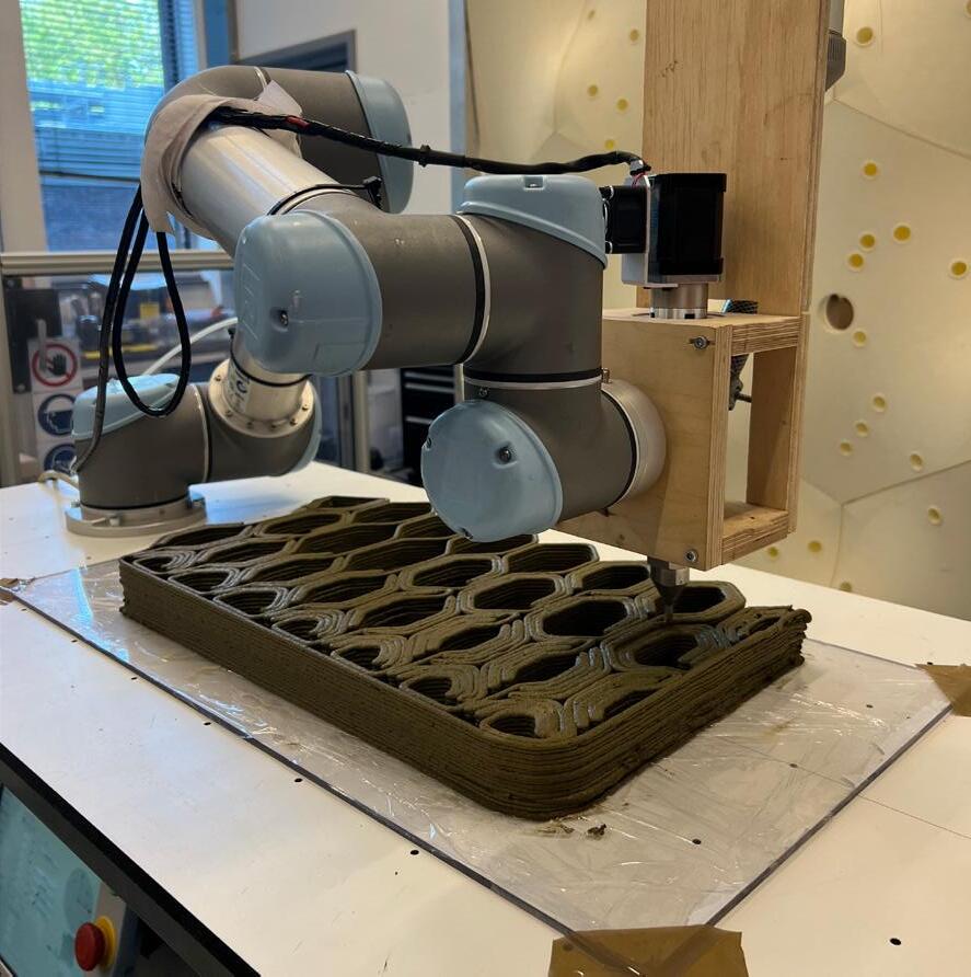
The primary objective of this research is to provide proof of concept for printing with bamboo. To achieve this, a 1:1 scale fragment of the design, explained in the Mechanically Informed Infill section, is prototyped. It was not feasible to print the entire prototype due to limitation of the robot work space, available materials, and tools, therefore a fragment of the overall design was prototyped. The selected fragment corresponds to a specific area within the component, which is determined by the reachable working area of the robotic arm.
While the printed fragment represents a smaller portion of the overall design, it serves as tangible proof of concept and provides valuable insights into the feasibility and potential of printing with bamboo.
Fig. 8: Mechanically Informed Infill Generation
Fig. 9: Prototype
Conclusion
This research project represents an innovative approach in the field of circularity and construction automation within the built environment. By exploring the use of bamboo in AM, it showcases the potential for sustainable material use and advanced fabrication techniques. The ability to re-use the printed component in the mixture enables a continuous printing process, reducing the need for new materials. The design process, informed by structural analysis and tailored infill geometry, showcases the potential of AM to optimize material use and create structurally efficient building components. The project addresses the need for renewable and eco-friendly construction materials, as well as the adoption of AM as a platform for material design. Through this innovative approach, the project contributes to the advancement of sustainable construction practices and highlights the possibilities for utilizing bamboo in the built environment.
Overall, this research project demonstrates the potential of bamboo fibers and dust as a valuable material for architecture through AM. The findings emphasize the benefits of incorporating bamboo into the construction industry, including its rapid growth, renewability, and versatile properties. By promoting the adoption of bamboo and AM techniques, the project contributes to circularity in the built environment and supports the transition towards more sustainable and efficient construction practices.
Jasmine wong @bk.tudelft
Jasmine Wong, 24 years old. After completing her bachelor in Architectural Design at Politecnico di Milano, she decided to pursue her master in Building Technology at TU Delft in the faculty of Architecture. During her studies she developed a strong interest in sustainable materials and innovative technologies like additive manufacturing. She is currently working in London as a façade engineer at Eckersley O'Callaghan.
DIGITAL CONCRETE PRODUCTION
Pioneering a new era of Digital Concrete Production and Working
Chris Aerts, Jeroen Veger @ Neolithic
Neolithic - unleashing the digital 21st century on the production of concrete and stone objects
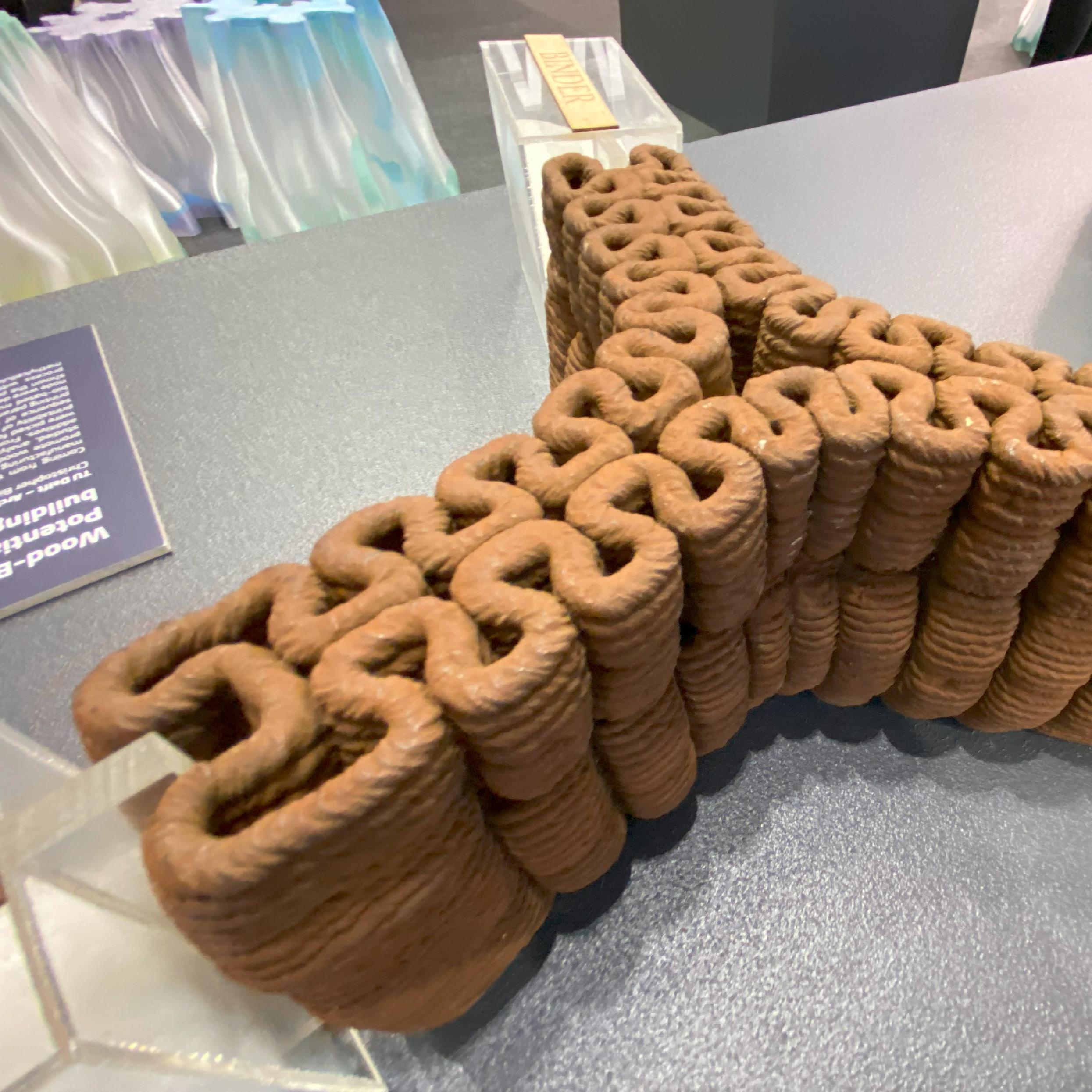
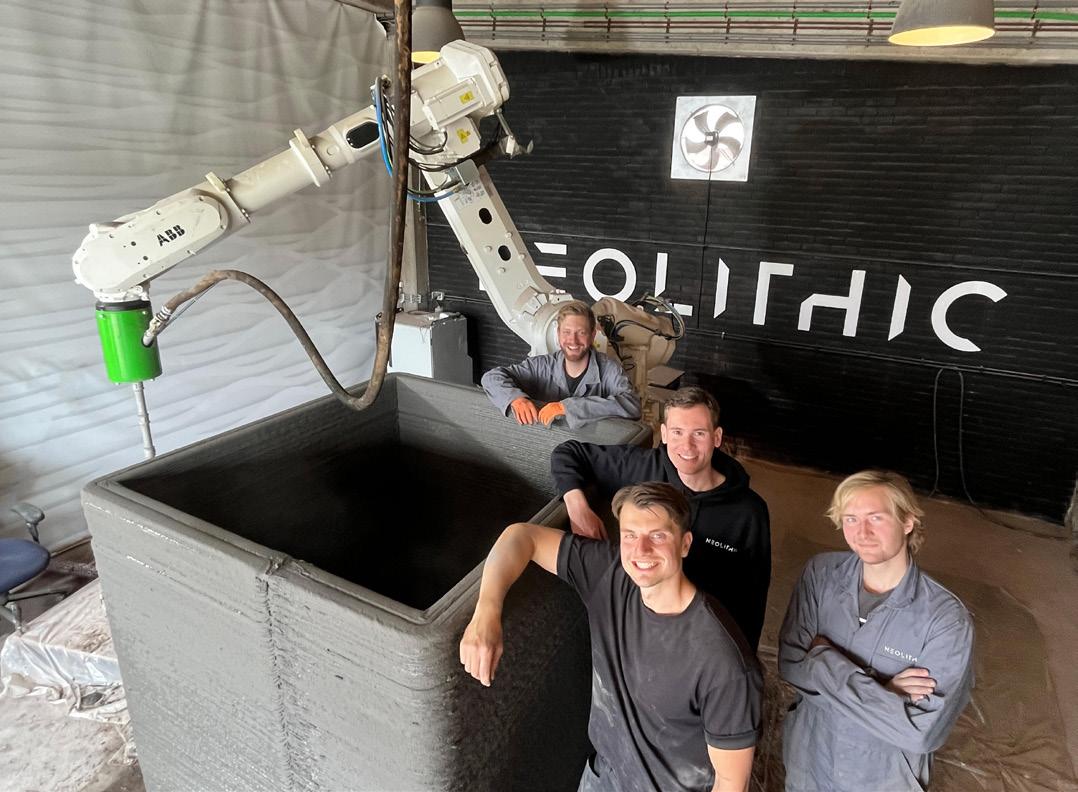
Neolithic is an innovative startup at the forefront of 3D printing and digital warehousing. Neolithic specializes in industrial 3D printing of concrete and stone objects using cuttingedge technologies, such as robots and industrial 3D-printers. The term Neolithic is a contemporary creation, derived from the Greek words νέος néos, meaning 'new,' and λίθος líthos, meaning 'stone.' Essentially, it translates to 'New Stone Age.' With advanced technology and an efficient supply chain, Neolithic excels at rapidly conceptualizing, printing, and delivering
high-quality products. The robotic production hubs primarily focus on the creation of modular construction and infrastructure components. Neolithic places a strong emphasis on product development and the startup also provide tailor-made solutions for unique designs in close collaboration with contractors, designers, artists, and municipalities.
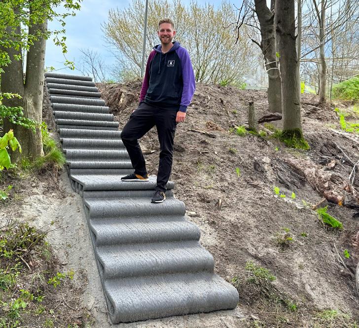
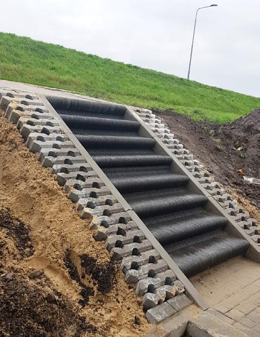
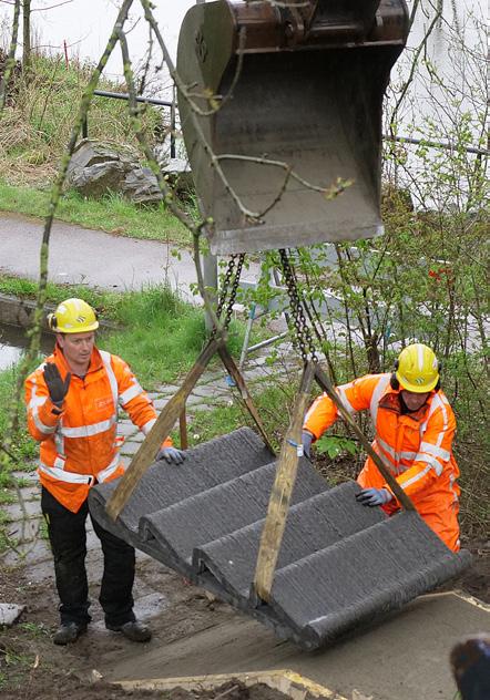
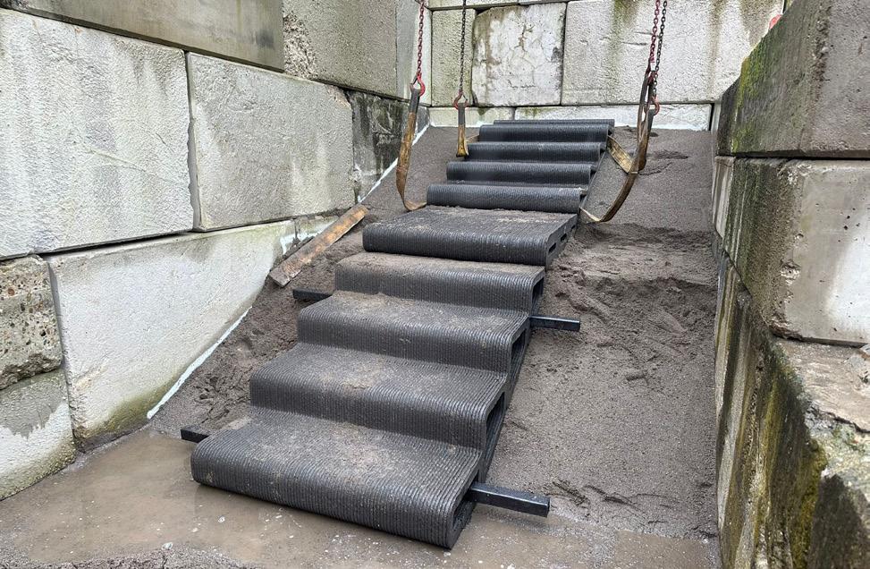
One of the flagship products is a mass-customizable sloped staircase. This innovative solution employs modular 3D concrete printed staircase segments that can be easily repurposed. Thanks to the material-optimized printing processes, these sloped staircases consume up to 50% less material compared to conventional concrete staircases. The Neolithic digital processes ensure a seamless transition from design to print data, resulting in quick delivery within a few weeks. Moreover, pricing is significantly more affordable than traditional methods. Neolithic stands as a beacon of efficiency and sustainability, setting a new standard in the construction industry.
Digital workflows for streamlined production
Neolithic's commitment to innovation extends to its optimized digital workflows, designed to streamline the production process seamlessly. Integrating digital technologies ensures not only the rapid production of on-demand products, but also allows for a level of customization that caters to the unique needs of clients. This digital-centric approach positions Neolithic at the forefront of modern manufacturing, especially in the construction industry.
On-demand production
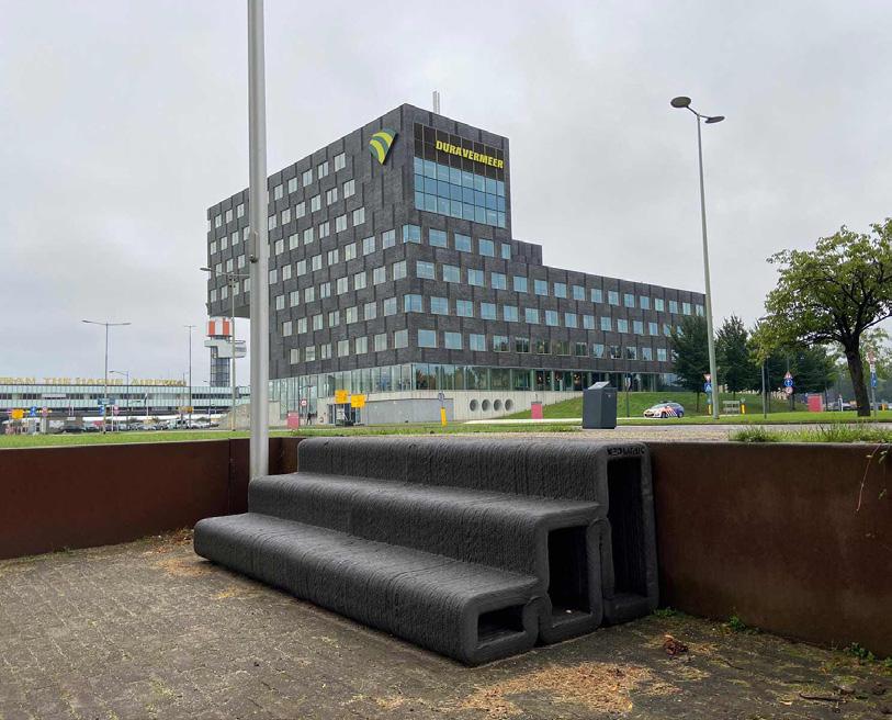
One of Neolithic's defining features is its ability to deliver swift, on-demand products configured to meet the specific requirements of their clients. Whether intricate infrastructure elements, architectural components, or bespoke design features, Neolithic's 3D printing capabilities allow for the creation of unique and highquality products optimized for diverse applications.
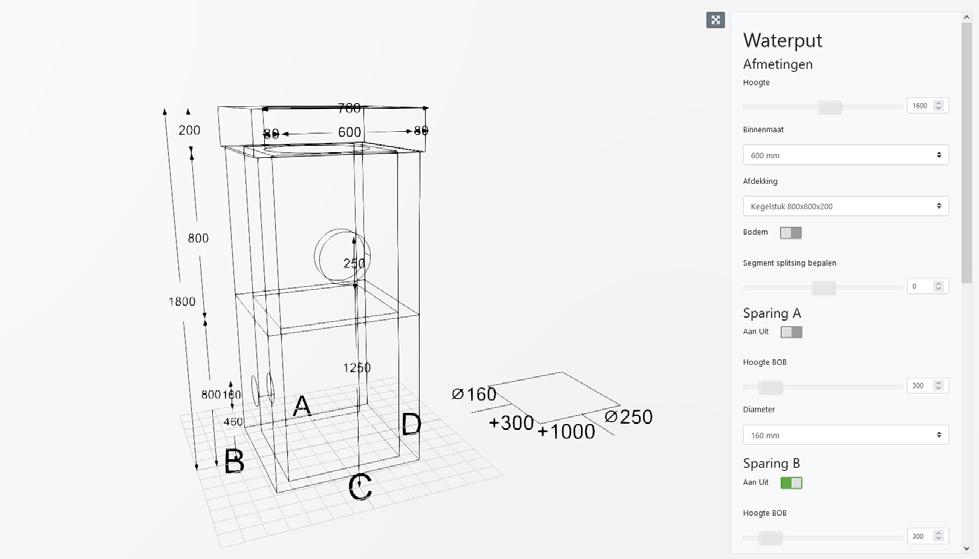
The key to Neolithic's recent successes lies in the online and supply chain integrated parametric configurators. This digital tool empowers clients to configure products such as wells, stairs, nature inclusive panels, or street furniture according to their unique preferences. Moreover, parametric design allows the company to integrate all processes into one automated workflow, meaning the printing can start directly after the client confirms the design.
Neolithic's online configurator acts as a design input tool, providing clients with a multitude of options to tailor their chosen elements. From altering the shape to adjusting the size. This flexibility is especially valuable in the context of infrastructure, architecture and design where custom solutions are often necessary.
ADVANCING AMSTERDAM'S CANAL INFRA-
STRUCTURE : Revolutionizing construction with efficient 3D-Printed wells
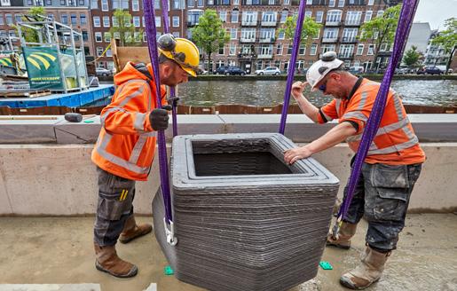
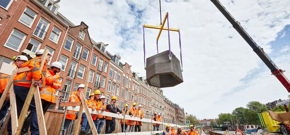
A fitting example of Neolithic’s workflow is the pioneering innovation of 3D printed wells. In early 2023 the company accomplished the production of a canal well in a mere twenty minutes, a task that would conventionally require a full day of skilled manual labor. This transformative project unfolded in Amsterdam, marking the installation of the city's inaugural 3D-printed canal wells and the first 3D printed well ever installed, meticulously printed down to the millimeter.
In order to achieve this innovation, Neolithic worked closely together with domain knowledge partners for rapid product development. In the case of these wells a partnership was created with Waternet, the municipality of Amsterdam and main contractor Dura Vermeer. The initiative was launched due to decreasing numbers of qualified labor for traditional made wells. Therefore Dura Vermeer opted to leverage the expertise of 3D printing from Neolithic to undertake the production of these cutting-edge wells. This partnership is accordingly fully in line with the municipalities and main contractor ambitions to robotize and digitize infrastructure works. Accordingly, a custom well configurator was created to facilitate a quick design to production workflow for this project.
Design parameters were developed in close collaboration with the partners. In the end it involves a straightforward digital process of entering height, width, and depth measurements. Following this, the design and production data for the robotic arm are generated automatically.
The integration of 3D printing technology not only yields significant time savings but also achieves a material
"Therefore, when Dura Vermeer supplied the measurements, our 3D printer could manufacture the wells the very next day. No engineer is needed for additional calculations. The whole process is automated."
- Chris Aerts, Co-Founder @ Neolithic efficiency gain of approximately 20%. Departing from the standard practice of prefabricated concrete drains, which often involve a two-month lead time and on-site adjustments, the 3D-printed canal wells are custom configured creations.
In the end, the printing process takes only twenty minutes per canal well, enabling Neolithic to complete this project in just over two hours. This represents a substantial timesaving compared to the traditional process, which would take at least a few weeks.
Chris is the founder of Neolithic with a strong interest in process optimization for the architecture, engineering and construction industry. He has years of international experience in the field of 3D concrete printing and parametric software development. He graduated at the TU Delft Architecture faculty, chair of Architectural Engineering. With Neolithic, Chris is combining robotics, parametric design and material optimization for configureto-order products. Ultimately enabling the innovation spiral for more efficient and material optimized construction processes.
Jeroen Veger @Neolithic
Jeroen is co-founder of Neolithic and also co-founded the 3D Makers Zone (3DMZ), a Smart Industry Fieldlab around industrial 3D printing and complementary smart tech, and BouwLab R&Do, an innovation hub around industralization and digitization of construction. He has 13 years of experience in the field of 3D printing, including applications, finding the right business cases and much more. Jeroen was always fascinated by the possibilities of next tech and during his Media study at the Amsterdam University of Applied Sciences he often organized sessions and meetings about the future of technology and digitization. He also has a background in branding and design.
AM ENVELOPE 2023
Current Classification of Additive Manufacturing in the Construction Industry
Dr. Holger Strauß, Innobuild GmbH
After more than 15 years of research and development, 3D-printed façade nodes and components are finally ready for real-time application in recent building construction projects. After his involvement in the early stages of development of those 3D-printed parts, the author is now summarizing the development of this last decade and gives an outlook from today's application to future needs.
Additive Manufacturing – A look back at 15 years of development
In this article, Additive Manufacturing (AM) processes stand as an example of how new technologies are changing construction engineering. The increasingly frequent use of AM in the construction sector shows a typical development of new technologies and can thus be used for evaluation and for formulating a perspective also for other currently pressing topics and techniques.
After more than 15 years of research and development, 3D-printed façade components are finally ready for use in actual building projects. To get to this point, considerable efforts have been made over the last 15 years and a large number of research and study papers have been written on this topic.
In order to provide a brief insight into the development of relevant components for façade application, the research project "AM Facades - Influence of additive processes on the development of facade constructions“ [1] is summarized and evaluated below.
At the beginning of the research project, the systemoffering of a façade system-provider were screened, and components have been identified that had a basic potential for optimization with AM.
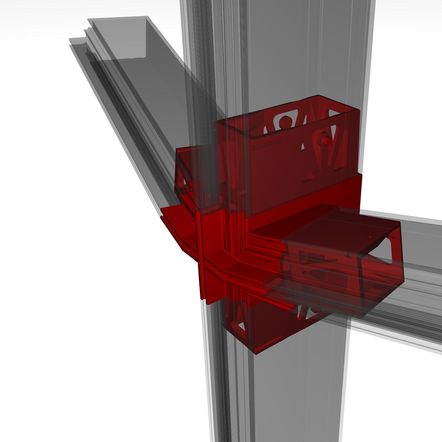
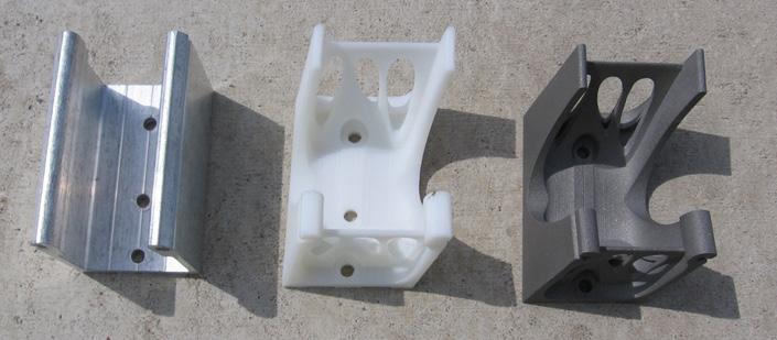
Due to the clear limitation of the AM-build-space size to produce AM-components in metal, a restriction to small and medium-sized components made sense. These included structural component connectors between mullions and transoms – so called T-cleats. Not only were the advantages of direct digital production considered, but also the given performance characteristics within the façade system. The optimized component is thus an improved "digital connector" that, in combination with digital planning tools, allows for individual façade geometries and enables a structurally optimized system.
All necessary angles and drillings are digitally integrated into the AM design. In this way, precisely fitting connections can be designed and manufactured for each connection point of the façade. The added value is achieved through material savings and force-path-
optimized shaping. (see Fig.2) Assembly is analogous to the orthogonal façade system with the standard mulliontransom system components.
The availability of additive processes thus added another link to the chain of a true "file-to-factory" production. It enables us to produce parts for a free-form façade with all angles and adjustments in the same quality as for an orthogonal façade with standard products.
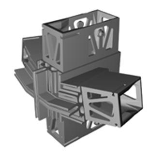
In the research project, the next step was taken from these "digital connectors" to develop a neuralgic node that carries all the complexity of the free-form geometry and leaves the other façade components as much standard as possible. All the advantages of the previously developed "digital connector" were further developed and combined into a customized, integral node. The resulting node was produced directly with AM. All required properties can be implemented digitally in the data set by setting design parameters (parametric design). Due to the digital fusion
of mullion and transom profiles, only right-angled saw cuts are necessary for the assembly of the façade. This reduces cutting scrap and facilitates assembly. (see Fig. 3a, b).
With this approach, a combination of proven standards and digitally enhanced node solutions was realized for the existing façade technology in 2010. By integrating new "high-tech" parts into tested and verified systems, the advantages from both areas could have been combined to an even better solution.[2]
To summarize the development of the last decade, it is necessary to differentiate the use and application of AM in the various industries. Industries with small quantities and component dimensions have been able to implement AM processes as an extension of traditional production technologies more quickly and easier than industries with large-scale components and a large batch number.
Looking at the construction sector, the following developmental steps were crucial for the maturation of AM:
• Materials
The AM industry has managed to further develop applications with metals from an initial idea to available technology. The variety of materials is almost unlimited and ranges from aluminum and
the needed equipment is available for workshop outfitting, and no more part of the industrial supply chain.
• AM-build-space size
The AM-build-space size has changed only slightly over the last 15 years. As a rule, the powder bedbased systems are still equipped with an average AM-build-space size of approximately width
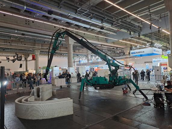
For direct building-scale applications, for example, concrete structures that are printed directly on
Fig. 4: Image Mobile Concrete Printer of www.constructions-3d.com ; picture taken at Formnext 2023
site are available. Several suppliers have adapted the ContourCrafting technology [3] for house 3D printing. The component size is not determined by a limited AM-build-space but is aligned according to demand by using crane systems and gantry robot technology. (see Fig. 4)
• Printing Speed
The acceleration of AM processes for metals has been undertaken with several light sources and in some cases several powder-coaters. Nevertheless, there are still narrow limits to both the achievable AM-build-space and the speed of printing. (cf. [2], chapter 2.5.1)
• Quality management
Today's service providers and AM-users meet the material quality standards and are monitored and qualified with Iso certificates. Consistent component quality is therefore now the industry standard. Onboard monitoring technology enables the realtime quality surveillance and offers detailed QMprotocols.
• Printing Cost
A calculation approach must be requested from the supplier based on concrete component geometries. The figures from the research project and current price quotations for the identical data set show the development with an approximate halving of costs to date
As the described research process shows, it was possible to subsequently move from our initial project ideas for façade applications to a resilient product development within fifteen years. It can be stated that AM is an available and proven building technology tool, but still a
niche building technology tool.
The initial idea of complete design freedom by eliminating tools, molds and creating shapes directly from a digital representation has only come to live in parts, as the available AM technologies are not yet capable of “doing it all” and there are still limitations in some important aspects of “Printed Architecture”. For the part of 3D-printed façade nodes it can be stated that here AM is ready to be a part of the production chain for façade manufacturing: the ongoing discussion is the price per piece, as still CNC milled nodal point in some cases are cheaper to be produced than 3D-printed ones.
But over all it can be observed that with the combination of increasingly powerful digital design tools, improved functionalities can be integrated and lead to greater benefits for the building envelope - and ultimately for the user. These include, for example, structural optimization, real-time simulation of environmental performances, solar radiation and shading of façades, wind and noise simulations and optimization of surface orientation – and some of them are realizable with AM.
Starting points for a contemporary implementation
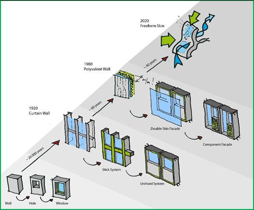
The Façade development as shown in Fig. 5 gives a rough overview over the last 20’000 years. After 22’023 years we have reached the predicted “Freeform Skin”, even with 3D-Printed Façade Nodes. Nobody would have expected that more than 10 years ago, when the underlaying hypothesis was formulated!
But it became reality from a "Funny Idea“ to a “System Offering”.
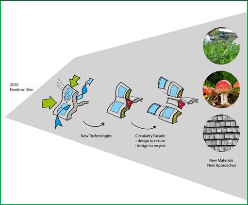
6: Adopted development of the Building Envelope from the “Freeform Skin”
Fig
Fig 5: Development of the Building Envelope towards the “Freeform Skin”
But what is next after this?
It is essential to emphasise the importance of the building envelope as a neuralgic interface to the different requirements of the building itself: climate protection and regulation; load transfer; user comfort; design and appearance. [6], [7] And the performance profiles of a building envelope can still be derived from these aspects, but today they are supplemented by the pressing issues of our time.
Today we are in 2023 and the objectives did change:
• We must work on new ways to reach the “Sustainable Development Goals” of the UN by 2030.
• We must reach the global goal of limiting global warming to "well below" two degrees Celsius compared to the pre-industrial age.
• We must realize carbon neutral buildings by 2040.
The performative properties of a sustainable building envelope must achieve significant improvements over conventional façade technology. Ideally, the requirements for a Dynamic Building Envelope can be met: Climate regulation through breathable materials, material savings through topology-optimized loadbearing structures, comfort through active insulation and ventilation, integrated technology for the user, performance for lighting and shading with adaptive transparency, circularity-compatible construction, and a design-compatible appearance.
Starting points towards “Better Building Technology” are:
• Optimized Material Consumption: Here, the goal must be to only use what is really needed. Softwaresupported optimization in structural design and
material efficiency can save resources.
• Reduced Carbon Emissions in Logistics: On-Site Manufacturing, rather than having parts prefabricated and transported to the site.
• Reduce by design: Refuse, Reduce, Reuse, Repair, Refurbish, Remanufacture, Repurpose and Recycle.
• Change from Linear Economy to Circular Economy!
We have technologies to support this change – one might be Additive Manufacturing. But regarding the claim of AM being a sustainable production technology, the actual Life Cycle Assessment of 3D-Printed Building Components must still be done and pursued.
Conclusion and Outlook
The Society must wake up and face the fact that things have to change in order to meet the declared climate protection goals - for our future, for the future of our children and for the sake of our way of living. With the awareness of the building sector being part of the cause of climate change, ways to practical solutions are needed in order to achieve the 2030 and 2050 climate change mitigation goals in Europe.[8]
With the lessons learned in AM - from the passed “Technology Hype”, through the “Trough of Disillusionment” and onto the ”Plateau of Productivity” [9], it is possible to see a parallel detection in the past research and the needed new topics, to give an outlook towards future façade applications.
To achieve this needed change within the construction industry and within the niche of the Building Envelope, the indispensable next steps can be appointed as follows:
• Sustainability and the way to a circular economy, with a first step of introducing circularity in façade construction.
• The application and combination of new construction materials to achieve a more thoughtful use of valuable resources.
• Reformation of traditional planning processes to bring the life cycle of building envelopes toward contemporary realization.
With this societal change in awareness, a change in the building industry will also become easier and the discussion will shift towards a greater willingness of investors, builders, and stakeholders in the building industry to explore new ways of realizing projects. This will bring new solutions to the fore, even if they may initially involve higher costs. The façade industry is also slowly adapting to these new ways, and everyone can participate in this change by finding improved solutions to existing problems.
Based on the experience in the development of 3D-printed façade parts and components, starting with early developments as mere prototypes and ending with accepted (building) technology, it must be stated that new technologies and innovations take ten to fifteen years to come from vision to application. So, we must start now to make changes for the future.
"In the end, it is a well thought-out combination of design and material that makes for sustainability." [10]
1. Strauss, H., AM Facades - Influence of additive processes on the development of facade constructions. 2010, Hochschule OWL - University of Applied Sciences: Detmold. p. 83.
2. Strauß, H., AM Envelope - The potential of Additive Manufacturing for facade construction. Architecture and the Built Environment, ed. A+BE. 2013: abe.tudelft.de.
3. K hoshnevis, D.B. Contour Crafting Corporation. 2017; Available from: http://www.contourcrafting.com.
4. Architekten, M.-K. i. HOUS3DRUCK. 2020 [cited 2022; Available from: https://www.housedruck.de/.
5. K G, P.V.D.G.C. PERI druckt erstes Wohnhaus Deutschlands. 2020; Available from: https://www.peri.de/ informationsportal-news-medien/veroeffentlichungenpresse/peri-druckt-erstes-wohnhaus-deutschlands. html# q=3D%20Druck.
6. K naack, M Bilow , Auer , Facades - Principles of Construction. Principles of Construction. 2007, Basel: Birkhäuser Verlag AG.
7. Martin Meijs, U.K., Components and Connections. Principles of Construction. 2009, Basel: Birkhäuser Verlag AG.
8. Commission, E., et al., How to assess climate change mitigation potential at project-level? : an estimation based on life cycle assessment of project proposals submitted under the European green deal call. 2022.
9. Peels, J. Where is 3D Printing in Gartner’s Hype Cycle? 2022 [cited 2022 22-05-18]; Available from: https://3dprint. com/291020/is-3d-printing-in-gartners-trough-ofdisillusionment-or-slope-of-enlightenment/.
10. Röder, D.A. Die K ombination aus Design und Material macht Nachhaltigkeit aus. UmweltDialog WirtschaftVerantwortung-Nachhaltigkeit, 2020.
Dr.Ing. Holger Strauß is a specialist façade-engineer and a registered architect. Since 2022 he is partner at Innobuild GmbH in Berlin. There he is currently building up the "Innobuild Future" R&D-division with a focus on the topics of circularity, sustainability, renewable energies, and new materials for the building envelope.
Holger studied architecture at the University of Applied Science, Detmold, Germany, and completed his doctorate in 2013 at the TU Delft, Netherlands. Since then, he has gained professional experience in various positions in façade engineering and in architectural offices in Germany and Switzerland.
Dr.Ing. Holger Strauß
STUDY- VISS³ FREEFORM FAÇADE
With 3D printed steel nodes
Sebastian Thieme, Head of Development at Jansen AG
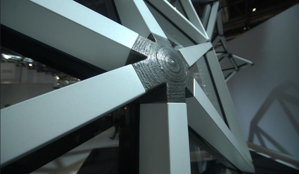
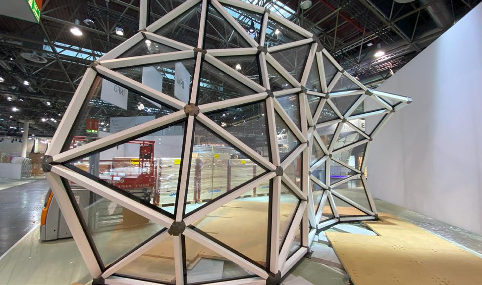
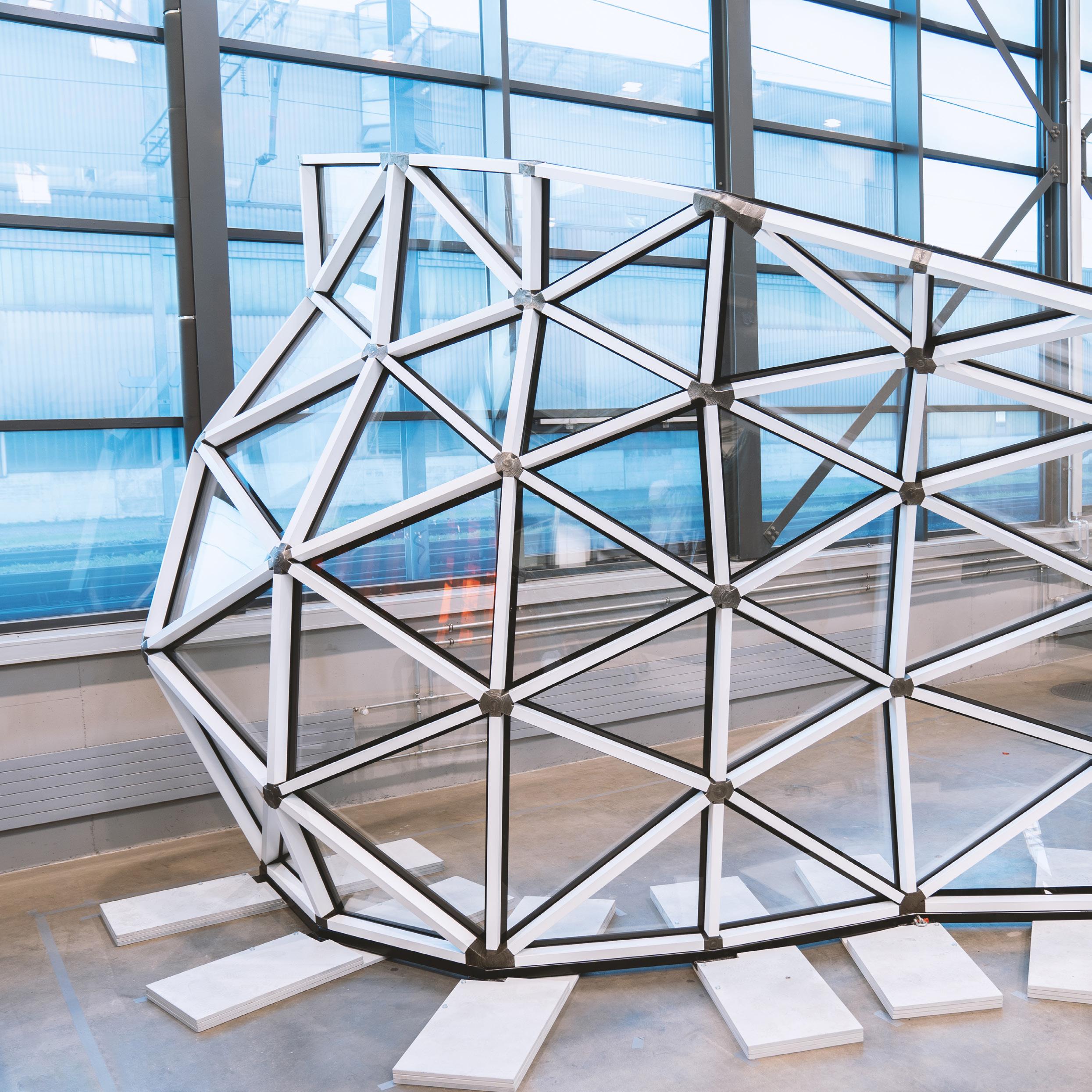
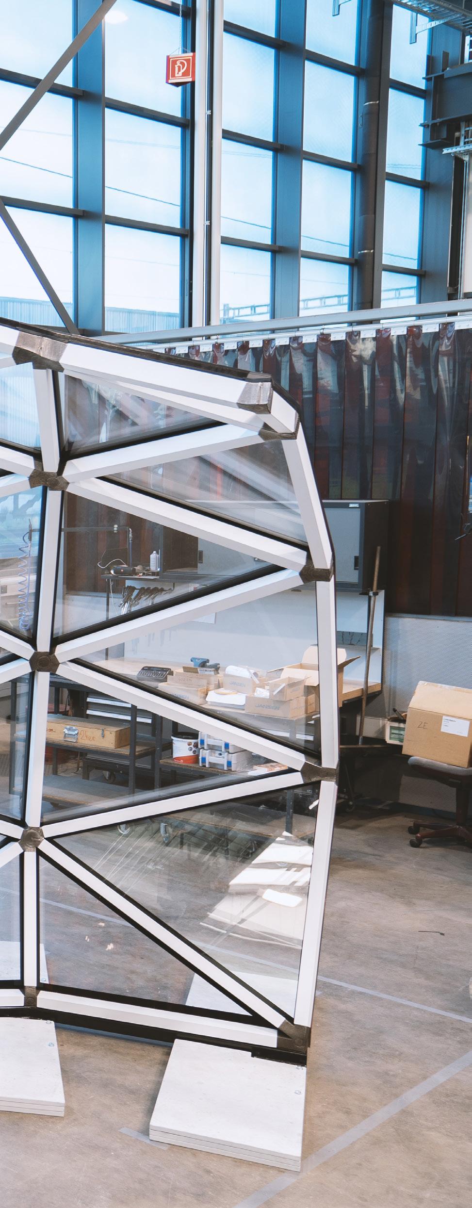
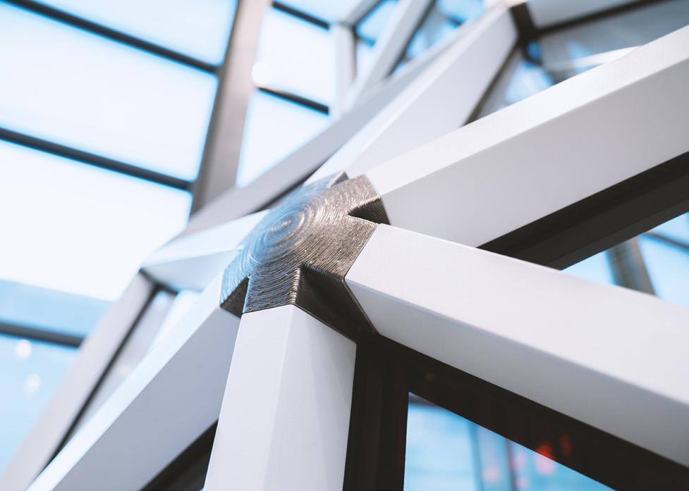
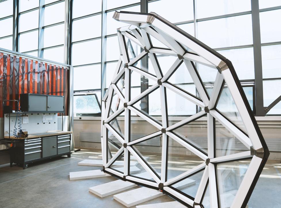
A study on VISS³ free-form façade with 3D printed steel nodes New designs have become possible as 3D printing with steel takes the VISS façade into the third dimension: VISS³ creates connections by combining the tried-and-tested VISS systems with 3D printed steel nodes. This results in fascinating freeform façades that require no substructure at all.
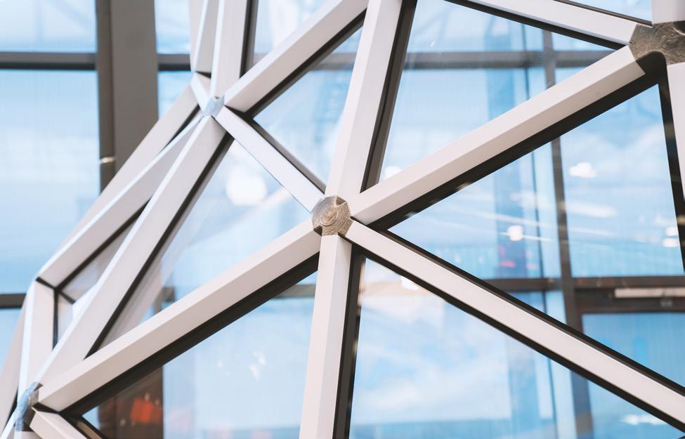
As part of a research cooperation with TU Delft in the Netherlands, the engineering company knippershelbig GmbH in Stuttgart, Germany, and MG Metalltechnik GmbH in Matrei, Austria, Jansen has investigated the options for using 3D printing technologies to manufacture steel nodes. This new technology offers architects previously unimaginable design freedom for steel system façades. The 3D printed steel nodes combined with VISS profiles form the foundation for constructing concave and convex shapes. The nodes can be formed on a bespoke basis with multiple arms and different angles, allowing both acute and obtuse angles to be created within a single node. The VISS³ façade is self-supporting; load is transferred directly via the profiles and connecting nodes without the need for a substructure. In this way, Jansen VISS³ enables the construction of complex free-form façades and roof lights of any shape.
The study on the VISS³ free-form façade received a special honour as part of the Architecture+Building Innovation Prize at the international trade fair ‘BAU’ in
Munich (Germany).
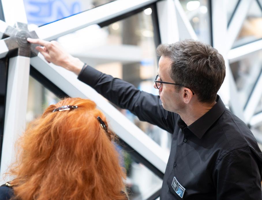
Sebastian Thieme, Head of Development at Jansen says: “The cooperation with TU Delft, knippershelbig and MG Metalltechnik was inspiring and valuable for us from start to the end. When investigating how to produce the Jansen VISS³ free-form façade, particular attention was paid to the gasket level. The overlying gasket nodes are printed to match the connecting nodes so that drainage is provided via just one gasket level. At the same time, the concealed connection ensures a homogeneous appearance”.
3D printing process
DED (Direct Energy Deposition) refers to a metal 3D printing technologies in which components are produced by melting the starting material, which is usually a metal powder or wire. The metal powder or wire is fed through a nozzle and melted using a focused energy source (usually a laser or electron beam).
SLM (Selective Laser Melting) refers to a powder bedbased metal 3D printing method in which the starting material, usually metal powder, is applied in very thin layers and fused into solid structures by a laser beam with pinpoint accuracy according to geometric specifications. This process is repeated layer by layer until the component has been completely built up.
Design details of free-form façades
Free-form nodes made of steel or stainless steel are produced on a bespoke basis for VISS³; the basic construction utilises standard items from the VISS system façade (Refer QR 3 for the page link for VISS system façade). This makes installation quick and easy as the node and profile connect without any special tools, thereby simplifying the process. The high corrosion resistance of stainless steel and coated steel ensures durable and robust free-form façades and roof lights that continue to work reliably for decades. Last but not least, steel is a 100% recyclable material that has long met
the criteria for greater sustainability in the construction industry.
Maximum transparency in the building shell
By combining 3D printed steel nodes and slim VISS system profiles, Jansen VISS³ provides the perfect foundation for installing large panes of glass. 50 and 60 mm wide profiles with different profile depths can be used. Large glass elements and low-visibility frame profiles let in as much daylight as possible, helping to reduce energy costs. Furthermore, three-dimensional façades withstand higher wind loads than flat surfaces for the simple reason that the wind load is swirled against many smaller subsurfaces and pushed away. This results in unique building shells with maximum transparency.
Head of Development, Jansen AG (2021-today); Head of Technical Competence Center, Jansen AG (20162021); Technical Consultant, Jansen AG (2014-2016); and Research Engineer, Technische Universität Dresden (Germany) (20072012).
Researching adhesive connections in glass structures and façade construction. Also involved in Teaching engineering students and postgraduate engineers in façade construction and glass design.
Structural Engineer, Arup (London/UK): Project engineer on various international projects with a focus on facade construction and glass design.
Education: RWTH Aachen University, Germany: Civil Engineer; University St. Gallen (HSG) Switzerland, Executive MBA; Polytechnique Montréal (Université d’ingénierie)
@royal
@royal_haskoningdhv
Contribute to the feeling of comfort at Royal HaskoningDHV
On a daily basis, our colleagues craft environments that seamlessly blend user comfort with eco-conscious design, offering a harmonious experience for both people and the planet. And the most inspiring aspect of all is that you get to work with a lot of in-house experts: engineers, architects, manufacturers and builders. Every day is different, whether you are a building technology engineer, mechanical or electrical engineer, fire safety consultant or acoustics & building physics consultant. You will work for a variety of clients, like hospitals, data centres, laboratories, airports, museums, theatres, performance halls, industrial plants, offices and housing.
▶ Ready to elevate environments?
Scan the QR-code, read more about the experiences of our colleagues and explore your job opportunities!
SAEKI Towards Decentralized Fabrication Hubs
Matthias Leschok, co-founder and COO of SAEKI Robotics AG, in conversation with Fieke Konijnenberg and Mauritz von Kardorff from RuMoer
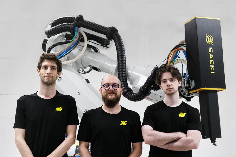
SAEKI was founded in 2021 by Matthias Leschok (COO), Oliver Harley (CTO) and Andrea Perissinotto (CEO). It is a fast-growing startup, based in Zurich and caters to the demands of the digital construction industry of tomorrow. With their micro-factories, SAEKI delivers digitally manufactured large-scale polymer products for the construction industry and beyond. Through their robot as a service model, they aim to make additive manufacturing more accessible for a broader range of companies and markets. This interview was conducted in December 2023.
RuMoer: To start the interview, we have a broad question, to understand your approach and how you might position your firm. How do you as a company envision the construction industry in the next 10 years and the next 50 years?
Matthias: There are classic factors to consider: we know that we need to build more buildings to keep up with the predicted population growth, which is already happening. We also know most of this is happening in the Global South. From my point of view, there will be a clear difference in construction in Europe and the Global South. In Europe, the construction sector will most likely be about high-performance new constructions and renovations, that limit CO2 emissions during the lifetime of a building. Whereas in the Global South, the challenge will be to provide adequate housing for people. Besides that, there are the challenges we probably all know about; the construction sector uses approximately 40% of all the energy, 40% of the waste, and 40% of all the resources that get extracted from the ground. These are some major challenges that need to be tackled in the next ten years and we need to start tackling them now already. The construction sector is also one of the least digitized sectors on the planet. We think this needs to change. Talking from the perspective of the start-up: when talking to people, we notice they don’t quite know yet how to use digital techniques or what digital techniques can do. But we can tell there is eagerness to try out something new.
RuMoer: So your aim is to innovate the construction sector with new digital techniques. What exactly is the product you offer as a company? And what does SAEKI stand for?
Matthias: The name SAEKI refers to a Japanese sword master, which is linked to one of our co-founders who loves Japan. SAEKI provides digital manufacturing technologies. This can be 3D printing, milling, coating, etc.. We think this service needs to be as easy to use as an iPhone. So currently, we are preparing the first decentralized production hub of large-scale digital manufactured products. The idea is that we have something called a ‘micro-factory’, which consists of a robot with a minimal footprint. This micro-factory is able to produce elements autonomously. A few things the robot would be able to do, are pick up and use tools, or process a surface, for example, to produce a smooth surface finish on a concrete formwork. Then, it is able to grab a scanner to make sure that the piece that we have manufactured is actually what we need. In this way, we also have a digital twin of our printed object. We are currently establishing our first local production hub, a factory full of micro-factories, in Switzerland. In our robot-as-a-service business model, a company does not need to purchase and operate the machinery itself, SAEKI is taking care of this. They have all the benefits of owning a machine, without the challenges that usually come with it. We are lowering the hurdle that you need to overcome to digitize the construction sector.
RuMoer: Exciting! Where did the idea for your company come from?
Matthias: Our concept originates from when we were all still at university. I bought one of those readily available extruders. I received a bunch of cables that were not connected and a manual that was exactly one page, from there on I had to figure it out myself. And back then
there was no possibility for the tool and the robot to communicate. This is how Oliver, Andrea and I worked together for the first time. We saw that there was a need for something to solve this gap and developed a control unit connecting the tool to the robot. The tool knows when the robot stops, when the robot goes faster, slower etc.: very fundamental communication between tool and robot, which has developed further ever since. This worked so well with the big robots, but we also took the logic of the system and put it on a cobot system [Ed. Note: humanrobot collaborative robot system] with a filament extruder, so students can actually use it. The students from the MAS in Architecture and Digital Fabrication still use them every year. Most of the things that you see on the program's home page, when it comes to plastic printing, are the prebirth of SAEKI technology.
RuMoer: Which academic background do you and your fellow founders have?
Matthias: I studied architecture and then followed the MAS Digital Fabrication program at ETH. Afterwards, I started a Ph.D., which I'm handing in by the end of January 2024. Then we have Oliver, who finished his Master's in Robotics, and Andrea who is an Electrical engineer. We are very interdisciplinary. All of us studied at ETH Zürich, where we met as well while implementing robotic pellet extrusion.
RuMoer: How would you describe your offer and how is it different from other robotics companies?
Matthias: From a customer perspective the product is the printed piece, and this could be for example the formwork for a concrete piece or a mould for a carbon fiber component. There are a lot of companies that sell you the hardware, and you do all the rest that comes with it yourself. This includes all the engineering, toolpath planning, operating the machine, etc., which places the boundary and the frustration level to enter the field often quite high. We would like to avoid this and do not sell our hardware. If you want something, you lease our capacity to produce something. I think that is the major difference between us and other companies.
RuMoer: Are your typical customers then usually experienced in additive manufacturing?
Matthias: I think currently we don't have a typical customer. Some have experience in 3D printing, might also own a small 3D printer and have tested the material before. Now they want the option to produce something bigger, so we produce those pieces. Then we have construction companies that want to do something with
Fig. 2: Oliver Harley, Matthias Leschok, Andrea Perissinotto
digital manufacturing techniques, but they don't exactly know what yet. A lot of people are now able to design using computational tools, but only a few people can manufacture them at this time. For example, we just finished a project with a local Swiss construction company. They made a Grasshopper and an ArchiCAD file to make a twisted column, but they told us that they could not find someone to produce this formwork for on-site casting. There was no one to do this in a reasonable amount of time, at a reasonable cost. That was the moment we crossed paths. We made this column formwork for them, whilst they had no previous experience with 3D printing at all.
RuMoer: What is the material you then print with?
Matthias: Right now, our extruders are using thermoplastics. There are different types of
thermoplastics we can use. We can produce elements using polymers that are easy to recycle, or biodegradable ones. The possibilities here are quite broad.
RuMoer: We started this interview with the question about how you envision the construction sector in the next 10 to 15 years. Where would you position SAEKI in those regards? Which issues will you be tackling and in which areas of expertise?
Matthias: The idea is to have a lights-out factory, meaning a human comes in and brings raw material into the system. The robots start producing; one robot ‘ghost’ picks up elements, then brings them to the next one, and ideally, finished parts come out at the end. There are a few examples of lights-out factories already. I believe that increasing the level of automation is crucial for us because this allows us to overcome the lack of skilled labor. In addition, this allows us to produce complex designs, enabled through computation design tools, in a cost-effective way.
RuMoer: So you want to innovate the building sector by automating the process as much as possible and thus make it accessible for a wider audience.
it. I am convinced the drawing is not needed anymore; this kind of work can be optimized quite significantly. Eventually, this technology is then linked to the quoting platform. If a product is designed for our production W'we don't throw anything away at SAEK I, we pick up the shavings and collect them in a bag. Once we have enough, we ship it out to get it recycled'
process, I can directly tell you how much material we will use, and how long the robot will print, which defines the cost. After this, robots will take over and produce the product. We can either produce formwork that can be used on-site, or on a precast facility. This brings us to another super important factor, recycling the formwork that has been used, given that 3D printed formwork is most likely going to be used for nonstandard elements. You will probably not use our printed formwork a hundred times, but maybe twenty to fifty times. This is why it is important that we put the plastic that we have taken out of the system back into it again. We therefore have the buyback option. If we make you an offer, we will buy the formwork back from you after use. We actually took back formwork from a construction site recently and are now collaborating with a research institution in Aarau, allowing us to recycle this used material. If we talk to potential customers, this aspect of formwork recycling is very important to them. We see there is great potential in making bespoke concrete architecture more accessible while keeping the waste generated at a minimum.
RuMoer: Which polymers do you use to recycle them easily? And does that mean your idea is to recycle inhouse and reuse the material yourself to produce new products, or do you bring the used material somewhere else?
Matthias: We use different materials; PP-based polymers, ABS with carbon fiber, PETG. In theory, all those materials can be recycled very well. Working with wellestablished materials, like PP, allows people to know how to handle and recycle the material. In order to recycle polymers efficiently, you need big batches of material, 1 ton or more. If there was less, it would not be worth turning on the very big machinery necessary for recycling. That is the reason we will not recycle in-house and work together with local recycling companies. We don't throw anything away at SAEKI. We pick up the shavings and collect them in a bag. Once we have enough, we ship it out to get it recycled.
RuMoer: Amazing. Is your robot also adaptable for use cases we have not discussed yet?
Matthias: Our micro-factory is super flexible. We have this backend infrastructure that we are developing on the hardware and the software side. It would be an easy change to put a concrete printing tool on the printers we currently use or alter it to print foam for example. The backend that we are developing is prepared for that. That being said, our micro-factory can not only serve the construction
industry, but also, for example, the automotive sector, or aerospace. If you change the polymer that you print with, which is one of the reasons we use polymers, then all of a sudden you can use the technology to make a carbon fiber tool. We could feed the machines with a high-grade polymer, which has a similar strength as aluminum. So, the micro-factory, this whole hub system, is not only about doing something for the construction sector. By localizing and bundling the machines, you can produce things for different sectors efficiently. As an example, one
week the micro-factory can produce formwork and next week you are able to produce for a local aviation company by switching materials. Making the use of our hubs very flexible.
RuMoer: That means you are envisioning the future of the company to expand outside of the construction sector?
Matthias: Yes, we are already doing that. We do have ongoing construction projects, but also have customers from different industries already.
RuMoer: How would you think that the challenges we discussed in the beginning of the interview can be addressed by the construction sector?
Matthias: Puh, that's a tough one! I think there are things that can be addressed right away like increasing awareness on the impact of the construction sector on our environment. If we shift from ‘we built as cheap as possible’ to ‘we try to build as smart as possible’, I am convinced that we can address the aforementioned challenges step by step.
With SAEKI, we aim to provide a platform that facilitates such decisions. By reducing the complexity of fabricating functional integrated elements, we can achieve precision and variability in components without increasing costs. In this way, we are able to create site-specific solutions that, hopefully, perform better than their off-the-shelf equivalents.
RuMoer: Thank you for this insightful interview Matthias. We wish SAEKI all the best for the upcoming years and your ambitious plans!
Matthias Leschok is a Ph.D. researcher at the Chair of Digital Building Technologies (DBT, ETH Zürich). His work investigates highperformance 3D printed facades systems and he is the author of a patented 3D printing technology. He has exhibited in various venues and events, including the Venice Biennale and the ZAZ Bellerive museum in Zurich. He is co-founder and COO of SAEKI Robotics AG, an ETH Spin-off developing decentralised production hubs for large-scale bespoke elements. In 2017 he graduated from the MAS in Architecture and Digital Fabrication.
Matthias Leschok @SAEKI
TRADITIONAL HOUSE OF THE FUTURE
Lidia Ratoi and John Lin @ The University of Hong Kong
The Traditional House of the Future proposes strategies for recycling and revitalizing vernacular houses, meanwhile seemlessly incorporating 3D-Printing technology. It follows up research on how self-builders are transforming their own houses as a response to the urbanization of rural China. The research demonstrates the necessity to evolve and adapt the traditional wooden house, incorporating modern amenities with flexible spatial organizations resulting from changes in livelihood. The project is part of a government plan in Nanlong Village, Guizhou Province, China, where hundreds of wooden houses are dilapidated and abandoned. It proposes a participatory framework for design and construction that combines robotic
on-site printing and traditional wood craftsmanship. Chinese traditional houses are built in such a way that they can be dismantled in a single day. The original house was scanned, and robotically printed walls were customized to incorporate the original structure, making it possible to design new spaces: planting, entrance courtyard, skylight, balcony, kitchen, and bathrooms. Local villagers dismantled and reconditioned the original structure, and once the walls were 3D printed, they were able to recycle and reassemble it into the new house. The project questions how technology can act as a social potentiator and become a means to strengthen local and cultural
building practices. Considering the existing built fabric as a “new nature”, which cannot be altered and therefore requires adaptation, the process touches upon key areas of sustainability: social, technological, and cultural.
About not giving up the past
Living in a world shaped by culture, nature, and now, technology, most find themselves at a crossroads beyond definitions. Neither rural nor urban, both traditional and modern, Traditional House of the Future is a prototype encapsulating the realities of a rapidly changing lifestyle.
Located in the Guizhou province of China, in the village
of Nanlong, it questions the built environment and its implications at the scale of time – past, present, and most important – future.
The project proposes strategies for recycling and revitalizing vernacular houses. It started as a collaboration between two bodies of work which are seemingly in opposition – investigations in rural China done by John Lin, and built projects in the realm of robotic fabrication by Lidia Ratoi.
Re-thinking the old - balancing tradition and modern needs
The Nanlong Village itself it situated at a crossroads –a village hosting mostly traditional wooden houses, it becomes slowly more and more obsolete, as residents are moving to the neighboring village, where they can get modern concrete houses for affordable prices. The research brought together many different entities: it is part of a government plan to revitalize the village, by offering a wooden house prototype that can respond to modern needs. The design brief for said prototype was done together by the two designers, as well as students of Hong Kong University, the team surveying houses and interviewing their inhabitants.
Following the interviews, it was discovered that villagers are giving up the traditional houses because they don’t have modern amenities (kitchen, bathroom etc), but also because there was no financial incentive to continue to live in the village. However, they were moving to generic concrete houses, which did not respond to individual family needs and were poorly built. Therefore, the question became – how do we re-think ancestral ways of
making, using their unique qualities, while creating space for modern needs?
Digital Fabrication meets traditional craftsmanship Working with robots and working with traditional craftsmen are similar methods, as there is no need for drawings –robots operate based on code, and woodworkers learn from mock-up models and adapt on site. Therefore, the
combination between the robotic printing and traditional wood working techniques was natural. Chinese traditional houses are built in such a way that they can be dismantled in a single day. The original house was scanned, and as 3D printing is a versatile method of designing and building, it was possible to accommodate for every imperfection, flaw or natural element of the ancient wooden structure. After dismantling, the wood was reconditioned, and the printing was done. The new walls allow for all the spaces established in the design brief with the villagers - planting, entrance courtyard, skylight, balcony, kitchen and bathrooms. It also permitted that a one level house, with a ground floor traditionally used for animals, to be turned into a two-storey house, as the villagers do not raise domestic animals anymore. The craftsmen then reintroduced the wooden structure, having to adapt the traditional way of building wooden frames and then erecting them. Throughout the entire process, there was a constant loop between the teams.
Adaption for the unique location
The remote location of the village posed some limitations – as the initial plan was to use cable or gantry bots, in the end, the only possible fabrication solution was to use a robotic arm. The geometry of the house, weaving from inside to outside, creating various indoor and outdoor spaces, not only respects the original wooden structures, but the limitations and size of the robotic arm. The project did not aim to push the boundaries of printing or make a statement in terms of robotic fabrication –instead, it proposed a methodology that actually allows experimental, state-of-the-art building techniques to be included in solving real life issues.
Challenging the perspectives on common practices of the built environment
Technology affects most of us, but often fails to benefit a vast majority of people. In this process of a prototype house that can be further tailored to fit different needs of different households, the entire village was involved: apart from working with the trained wood craftsmen, untrained villagers were involved in the construction by helping to reassemble the roof tiling. From the beginning to end, local dwellers were cooking, cleaning, waterproofing for the rainy season, and doing all the adjacent jobs. The construction process of the house became an opportunity to earn income locally, and found ways to integrate more type of workers apart from skillets robotic technicians.
The question of residents reactions came up often –however, the projects proposes a look into the traditional Chinese village that is beyond a romanticized, outdated view. Most of the locals have jobs related to technology
(the area being host to many “Taobao villages”, where most of the technology we use is produced), so their relationship to technology is natural.
The project gave an opportunity to consider key areas of sustainability – cultural and historical, environmental and technological – but its biggest driving force was to challenge, and counter propose perspectives on a currently rigid understanding of the built environment and the ones participating in or affected by it.
Assistant Professor - Lidia holds a degree in robotic fabrication from IAAC Barcelona, the Open Thesis Fabrication program, and has previously completed her master’s studies in architecture at UAUIM, Bucharest. In HKU, she is currently coordinating the year 2 undergraduate degree, and works on projects investigating material ecology and sustainability in the realm of robotic fabrication. She has previously taught at the Royal Danish Academy of Fine Arts, School of Architecture.
Professor of ArchitectureIn 2005 when the Chinese government announced its plan to urbanize half of the remaining 700 million rural citizens by 2030,John recognized that the rural is at the frontlines of the urbanization process, and together with Joshua Bolchover established Rural Urban Framework (RUF). Conducted as a non-profit organization providing design services to charities and NGOs, RUF has built or is currently engaged in various projects in diverse villages throughout China and Mongolia.
John Lin
@The University of Hong Kong
Lidia Ratoi
@The University of Hong Kong
BT SPOTLIGHT
Editor's note by Ramya Kumaraswamy
The Building Technology Course is one of the five mastertracks offered at Bouwkunde at Delft University of Technology. The master track focuses on research, technological design and innovation, dealing with the newest technology and interacting with the current market. This programme offers a balance between applied research and design of buildings and building elements.
BT Spotlight is a collection of works done by the students during their course. In this edition, BT Spotlight focuses on the integrated design studios- MEGA project and Extreme technology offered in the third quarter of the MSc1 BT program.
The next edition will present the works from two integrated design studios of the fourth quarter - User-Centred Sustainability Studio and CORE (COmputational REpertoire for Architectural Design and Engineering). RuMoer Committee looks forward to see what the next edition has in store.
MEGA is a collaborative integral multi-disciplinary design of a special big and/or tall building which could be a multifunctional skyscraper
or a multifunctional building with a large span. Disciplines involved are: architecture, structural design, climate design, façade design, design/construction management and computational design/ BIM. Sustainability runs transversally across these disciplines.The disciplines are divided amongst the team members; each member is responsible for the contribution and integration of these aspects in the collective design. Students are encouraged to match their role in the team with the specialization they follow in the Master track.
Fig. 1: Group work; render by Ruben V.
The ‘Rott Up’ is a high-rise building introducing a paradigm shift of urban land-use with its unique concept of combining a “macro-city”, serving the wider city at eyelevel by celebrating the urban flows by opening up to the Rotterdam Central station and Het Groot Handelsgebouw, with the “micro-city”, a city on its own, replicating urban life to create a sustainable and vibrant community in the sky. The robust superstructure and modular infill cubes ensures the building is futureproof by providing an optimal balance between longevity and adaptability. The design fosters a vibrant vertical community, departing from traditional anonymity and catering to the preferences of next generations, envisioning an engaging, selfcontained urban hub for both residents and visitors
Structural Concept
As the life span of the building elements has varying life durations, the structural design approach takes into account two main concept as “longevity” and “adaptability” (Fig 2). The primary structure, comprising
the mega structures and partial secondary structure are designed for longevity. These elements are constructed using concrete and steel to ensure their long-term stability and performance. On the other side, the timber structure is designed for adaptability, acknowledging the potential for functional changes in the future as well as rapid construction with the modular cube structures. By incorporating that, the building can be reconfigured or repurposed without compromising its overall integrity. This adaptability aligns with evolving user requirements by reducing the need for extensive demolition and reconstruction. Furthermore, as construction materials significantly impact the environment, this design maximizes timber usage despite challenges in using it as a primary high-rise structural element.
Primary Longevity: a versatile grid-truss system, spans 3.5 meters deep with a 4x4 meter grid, serving as a multi-purpose floor acting as a basement and supporting the six timber-cubed storeys (Fig 3). The vertical piers, strategically positioned around the cores, bear vertical loads and provide wind stability. These piers optimized load-bearing for individual towers, reinforcing the building's structure (Fig 4).
Seconday Adaptability and Longevity: timber glulam columns and beams, as modular cube structures, enable rapid construction and easy reconfiguration without compromising the building's integrity, crucial for the design's narrow plot size (Fig 5). In the macro city, concrete columns and beams are integrated. This ensures the necessary stability for mega structures while also serving an aesthetic purpose through exterior columns. (Fig 6).
Fig. 3: Mega Floors (Primary-Longevity); Ece S. & Pavan K.
Fig. 4: Vertical Piers (Primary-Longevity)
Group work in MEGA
Mega is a course, where students get to change to collaborate by focusing on diverse disciplines on designing a high-rise, that is a scenario is very similar to real life. The project has been done in close collaboration with each team member, the figure 7 shows which software was used by which role. It is divided into the main actions of the projects digital workflow.
Collaborating with a passionate group was a standout aspect of the course. From the start, all eight of the members dedicated hours to studio discussions, consultations with other disciplines while designing disciplined-based parts, ensuring every idea was
considered. The strong integration within the group reflected both in the project’s design results and the collaborative process itself, as well as everyone did learn a lot from each other. It was a great excitement to see at the end that to know that the design “does work”. Overall, the course was a great opportunity to experience an “a very like” real-life collaboration.
Team: Daniel Aristizábal, Dimitra Mountaki, Lara Neuhaus, Pavan Sathyamurthy, Ece Sel, Bo Valkenburg, Ruben Vos, Nils Wulfsen.
Received class awards: the most innovative design award & the most integrated design award.
data handeling communication analysing
data sharing
design explo.
Fig. 7: Digital workflows; Lara N.
Fig. 8: Group work; render by Ruben V.
BUFFERING OASIS
Carmen Guchelaar
Course: EXTREME Technology (AR0142)
The project is about building in a extreme situation, in respect to climate, location and function. Essence is the interaction between the extreme circumstances, the technical solutions, and the architecture. Extreme circumstances request technical solutions which will be the starting point for the design development. The designer has to direct the 'engineer questions and answers', towards the articulation of the form which is based on integration of aesthetic and technology. At the end of the course , the student is able to design a coherent, significant, elaborated, correct and innovative design - on mainline and on aspects – on Master 2 level.
In the Extreme course a design is developed taking into account Extreme weather conditions. This year the course location was Pakistan, where extreme heat and floodings occur. Half of the students worked on apartment buildings in an urban setting and the other half on incremental housing in a rural setting. This project worked on the latter.
Research
The first part of the project consisted of a small research into a specific topic of one’s own choice, which could later be used in the design phase. The combination of high temperatures and high humidity levels and bad excess to electricity in rural Pakistan, fuelled a research into lowtech solutions for dehumidification. A literature research and physical test gave the following conclusions which were used in the design: use of household desiccant materials; combine with induced ventilation; use building materials with humidity buffering effect.
Context and design concept
To accommodate for the extreme conditions a design concept was developed focusing on creating healthy and safe housing, which uses local materials and simple and low-tech construction and climate control methods. This to make sure the housing is affordable and the people can build and expand their houses themselves.
Construction and climate control
A step by step guide was developed to show how the housing can be simply built. The main building products were Compressed Stabilized Earth Block (CSEB) and bamboo and the building was elevated to be fully functional during most occurring floods. The focus for the climate control solutions (Fig 2) were that they had to be simple and low-tech. The main concept was that the building had a lot of thermal mass and with using protrusion and canals in the walls the active surface
area for the thermal mass could be doubled. The thermal mass functions to stabilize the indoor temperature. The double roof with overhangs shaded the building and night flushing could be used to get rid of heat. Furthermore desiccant materials could be used during humid periods to lower the humidity and wet clothes could be used for evaporative cooling during arid periods (Fig 3).
Reflection
This course gave the opportunity to dive into techniques and materials which would not be generally used in the Netherlands. Specifically focusing on simple and lowtech solutions was an experience which forced you to think outside of the box from which a lot was learned during this course. The most fun was made with making a lot of models and trying out connections and shapes in real life (Fig 4).
MEGA is a collaborative integral multi-disciplinary design of a special big and/or tall building which could be a multifunctional skyscraper or a multifunctional building with a large span. Disciplines involved are: architecture, structural design, climate design, façade design, design/construction management and computational design/ BIM. Sustainability runs transversally across these disciplines.The disciplines are divided amongst the team members; each member is responsible for the contribution and integration of these aspects in the collective design. Students are encouraged to match their role in the team with the specialization they follow in the Master track.
The design proposal by Team 01 for MEGA 2021, named "Makers 4 Future," represents a collaborative effort exploring the intricacies of high-rise building design. Emphasizing multidisciplinary contributions, the team, comprising nine members across various roles, aimed to integrate diverse perspectives into a singular, cohesive design. This report delves into the comprehensive design process and decisions made for the MEGA building, focusing on its integration within the urban context, functions, sustainability, and architectural intricacies.
Overview of the design and context
MEGA-2021 centered on a highrise building project that demanded meticulous consideration of design, computation, engineering, and construction management. The chosen site, M4H (Merwe-Vierhavens), poised for urban renewal, symbolizes a transition from a traditional port area to a dynamic district combining work, living, and production. Named the "Makers District," this locale fosters innovation, housing entrepreneurial ventures and knowledge institutions.
The design vision hinged on six core principles, emphasizing contrast, coherence, landscape integration, public orientation, extension of the Makersstraat, and architectural transparency. These principles aimed to harmonize the building with its surroundings, foster inclusivity, and exhibit innovative aspects while ensuring integration into the cityscape.
Functionality and Collaboration:
The MEGA building accommodates seven distinct functions, necessitating a cohesive integration of spaces. The collaborative process involved daily interactions among team members, ensuring each discipline contributed insights and solutions throughout the project stages. Challenges were addressed, and a balance between individual tasks and group dynamics was sought.
Management and Reflection:
Reflecting on the managerial role, there's acknowledgment of challenges faced, especially in facilitating interdisciplinary communication and setting clear visions from project onset. Learning from difficulties, managing remote collaboration, and guiding the team revealed the importance of clear communication and proactive planning.
Architectural Contributions:
The architect's role in synthesizing the project's interdisciplinary aspects emerged as crucial. The architectural design evolved from a clear concept, incorporating diverse functional needs and integrating with structural, facade, and climate considerations.
The MEGA 2021 project offered invaluable lessons in collaborative design, emphasizing inclusivity, sustainability, and integrative architecture. Despite challenges, the team's dedication and collaborative spirit underscored the creation of "Makers 4 Future," a landmark highrise embodying diverse functionalities within an innovative, urban context. Throughout the course, the primary challenge involved the integration of nine different styles and perspectives from various roles, resulting in numerous discussions on task allocation and individual responsibilities. Clear schedules and well-defined roles were deemed essential in navigating this collaborative process. As the architect, the experience provided a learning curve in managing a complex group project and effectively merging diverse strengths.
The workload proved notably high, presenting a significant challenge, yet the ultimate outcome showcased a wealth of details encapsulating extensive learning opportunities within a single building. Engaging in the MEGA course allowed for an exploration of the complexities involved in managing a multifaceted project with various stakeholders, honing skills in architectural design within a collaborative setting.
Simultaneously participating in the Extreme course provided unparalleled design freedom. While the depth of climate, structural, and building construction knowledge wasn't exceedingly high, the course facilitated the exploration of challenging concepts based on individual preferences. The relaxed schedule, supported by fantastic instructors, provided an environment conducive to learning without overwhelming time constraints.
Both courses held distinct strengths: the MEGA course enabled intricate collaboration and project management, whereas Extreme fostered creativity through freedom and real-case scenarios. Ultimately, these experiences enriched the skill set, providing invaluable insights applicable to future careers in architecture.
Team: Max Meere, Véronique van Minkelen, Frank Vahstal, Irene Zanotto, Mariana Georgoulopoulou, Thomas Lindemann, Feiyang Lei, Haihan Yu, Roy Uijtendaal.
RESILIENT RURAL HOUSING
Kuba Wyszomirski
Course: EXTREME Technology (AR0142)
The project is about building in a extreme situation, in respect to climate, location and function. Essence is the interaction between the extreme circumstances, the technical solutions, and the architecture. Extreme circumstances do request technical solutions which will be the starting point for the design development. The designer has to direct the 'engineer questions and answers', towards the articulation of the form which is based on integration of aesthetic and technology. At the end of the course , the student is able to design a coherent, significant, elaborated, correct and innovative design - on mainline and on aspects – on Master 2 level.
The project is a multi-person housing in Sibi in eastern Pakistan (Fig. 1). Sibi falls within a seismically active zone and experiences a moderate, seasonal flood risk due to its location near the Nari River. Most buildings in the region are made from Adobe, a low-cost, widely available and a fully circular material. However due to its brittleness, low tensile strength and behaviour when in contact with water it is extremely fragile during natural disasters. This posed a key and defining challenge for the project.
Unit’s geometry follows a shape of a catenary dome – ensuring that adobe is in compression only. It was further computationally optimised building on a thrust line analysis to ensure that a thrust line fits into the dome regardless of the in-plane earthquake direction (Fig. 2). The final structure includes deep concrete foundations, two layers of adobe brick with a bamboo mesh interwoven between the brick-work to ensure some ductility and wire wrapping placed around the openings of the structure to resist localised stresses.
The complex geometry of the dome, taking into account low financial resources of rural Pakistan, forced a search for experimental construction methods. The domes are constructed using a number of reusable formworks: wooden and pneumatic inflatable (Fig. 3).
In Sibi housing is in a constant state of change and evolution, adapting its capacity and boundaries to the changing structure of the family and the local community. With the evolving plan very often one unit might change its function multiple times. This was another key challenge for the project. To tackle that the brick domes, with a lifespans of several decades will be equipped with large openings to which modular facades can be fitted according to sun orientation, required privacy level, and spatial relation to other rooms (Fig. 6). The facades combine local, easily accessible materials such as bamboo, lime plaster and rice husk (Fig. 7).
In order to support the decision making of the local builders an algorithmic simulation of plans and façade panels was put together using Grasshopper. It shows different configurations of the floor plan and façade panels and can allow for simulations of its evolution.
The final problem was to ensure comfortable climatic conditions inside the units and protect from the desert climate of Sibi. This was achieved with insulating the wall’s cavities as well as ensuring cross ventilation within units. During the winter season the warm air can be trapped inside by closing a special opening at the top (Fig. 8).
Interview with Ece Sel (BouT Chairperson) and Sander Bentvelsen (Chair of Company relations) by Ramya Kumaraswamy and Fieke from RuMoer.
Rumoer: What is the debut event? What is the purpose of this event? Ece: The DEBUT event is an annual event of BouT and one of the highlighted student events within Bouwkunde TU Delft emphasising the pivotal role of student-industry collaboration while raising awareness about specific topics. As the DEBUT team, we view this as a significant opportunity for companies to engage with students who could become future employees upon graduation as well as to further collaborate with the other companies involved in the event.
Rumoer: What was the Debut 2023 theme about? Why did you choose this theme?
Ece: Every year, there are over a million earthquakes worldwide. Sadly, earthquakes have caused over a million deaths. We also witnessed this in the 6th February earthquake in Turkiye by causing casualties over 50 thousand in Turkiye and Syria and affecting 16% of the Turkish population. A similar earthquake happened in Morocco by causing over 3.000 lives. Thus, by taking in consideration those natural disasters we chose to focus on earthquakes as natural phenomena and them turning into disasters. As a person, who has closely witnessed the amount of destruction the earthquake provided for my own country, I specifically felt the responsibility to do something as much as we can, at least raising an awareness and brainstorming on the possibilities. The key question guiding this focus is the understanding that natural phenomena themselves aren't disasters inherently; rather, it's our response and preparedness that determine the scale of the disaster. As engineers and architects, there's a pivotal role in designing and constructing structures that minimise damage and enhance safety, potentially averting such catastrophic outcomes.
Rumoer: What was the case designed for the students?
Ece: We focused on an earthquake-prone zone, aiming to generate ideas that could significantly reduce potential damage. Presently, Istanbul is expecting a major earthquake proven by scientific data, with a Mw around 7.2, which is believed to be highly destructive. We obtained information from the Istanbul Municipality concerning estimated losses and damages in the event of an earthquake. Furthermore, we contacted the
Municipality to procure real-life documents regarding a school building evacuated due to the risk of collapse during this expected seismic activity. The students and attending companies were asked to focus on one of the proposed scales and intervention levels to mitigate the risk by thinking about the local people, economy and the rich history the city has.
Sander: The students were given the choice of selecting their own emergency management phase, and intervention level when thinking about earthquake management in Istanbul. They could focus on Mitigation, Preparedness, Response, or Recovery and combine such a phase with either the urban, architectural or technical scale. Giving the students this amount of freedom was useful to allow the varying range of companies to assist with their own experience. For instance, a company with structural knowledge could collaborate with students to come up with an innovative bracing system on the technical level. While a company more focussed on computation was free to develop a framework for building retrofitting assessment in the city.
Rumoer: What companies were involved? Did they have any prior experience/ expertise in the debut topic?
Sander: This year, in no particular order, the attending companies were Witteveen+Bos, Scheldebouw, RoyalHaskoning, OMRT, Mobius Consult & Aldowa. It’s a range of engineering and consultancy firms that specialise in varying disciplines in the building industry, for instance: area development, structural and façade engineering, climate and sustainability, parametric design etc. What was difficult this year was to connect the companies’ expertise with the topic of earthquake resilience in Istanbul, as not every company had the prerequisite knowledge or experience in tackling earthquake prone regions. However, like I said, we tried to phrase the problem statement in such a way that allowed the companies to apply their knowledge in a more widespread manner. That being said, I will advise the planners of next year’s event to ask the companies themselves to come up with their own cases. This is how the day was structured in the past and remains a golden formulae for student and company collaboration.
Rumoer: How was the whole day designed/scheduled?
Sander: During the first half of the day the students that attended the event got to meet the companies they signed up for prior to the event. In three 30 minute sessions company representatives got to explain to groups of students what their company does and why they are interested in us as building technology students, after which there was time to ask questions. It’s actually very similar to an information market.
Then the second part of the day started, focussed around earthquake resilience in Istanbul. Here Job SchroënBK spoke about his experience in earthquake resilient
After lunch the students got to collaborate with their chosen company and together they developed a range of design solutions, which they presented at the end of the day. With the help of our guest jury there was an award ceremony and finally some concluding drinks at the Bouwpub.
Rumoer: What was the outcome of the event?
Ece: We achieved great outcomes by the end of the event, even though it was a short workshop day. Creative ideas surfaced as it provided an excellent opportunity to brainstorm collectively with students and attending companies. Some groups developed interdisciplinary ideas, integrating mapping, technical technologies and architectural approaches, while leveraging the diverse
expertise of the companies. Other groups focused on creative technical and structural details to mitigate earthquake magnitudes, and some directed their attention towards the local community, identifying their needs while preserving their history and culture. Ultimately, three different prizes were awarded by the Jury Members: Simona Bianchi, Job Schroën and Marcel Bilow.
• The Most impactful: An Urban Solution for Earthquake Prevention, by Shake Up (Witteveen + Bos)
• The Most collaborative: Locating Safe Spots by Safe Havens (Royal HaskoningDHV)
• The most innovative: One damper to rule them all by Lord of the Ring moBius Ring (moBius Consult)
One of the most crucial aspects of this collaboration was the diversity of backgrounds and focus areas among participants, which significantly strengthened the end results. It was evident that many groups combined the innovative ideas of students with the creative perspectives and technology offered by the collaborating companies. We hope that some of these projects might serve as an excellent starting point for further earthquake-resilient initiatives for students or anyone interested in this field.
Rumoer: How was your experience in organising the event?
Ece: From the start, we had a great Debut team excited about organising the event, and felt honorful to do something for a global problem. With our special guest lecturer Job Schroën, TU Global Student Association and our Jury members the event even became stronger. Collaborating with attending companies was one of the fun parts of the day. Also as the Debut team, we did have
fun along the way. One of the most important things we have noticed is that we do have impacts within the events we realise whether it is just raising awareness to a global problem or initiating an idea. Thus, we always should put our efforts to do something for a better society. I specifically would like to thank the main chair of the Debut event and my co-organizator, Sander, for his effort and of course the whole team!
Sander: It was a great experience! It was fun to see so many people with so much input and a great feeling having organised such a day. In the end the effort of 14 of our students helped to organise this day in some way or another, so having this many people on board was of great help. The feedback we received was mostly positive, I was told it was generally well structured and people told they enjoyed the day. Even if the award ceremony became a bit hectic at the end, or that the case challenge could’ve been more applicable to the expertise of companies. I feel like the students and companies truly connected with one another and now have a better understanding of one another. Ultimately that's what this day is all about.