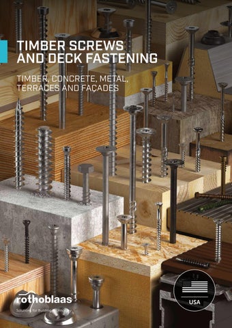
TIMBER SCREWS AND DECK FASTENING TIMBER, CONCRETE, METAL, TERRACES AND FAÇADES
USA
Solutions for Building Technology
TIMBER
17
PARTIALLY THREADED - COUNTERSUNK HEAD
PLATE FASTENING
SHS.................................................. 18
HBS PLATE...................................242
SHS AISI410...................................20
HBS PLATE EVO......................... 256
HTS..................................................34
HBS PLATE A4............................. 271
HBS..................................................36
LBS.................................................272
HBS COIL.......................................52
LBS EVO.......................................278
HBS EVO........................................54
LBS HARDWOOD...................... 284
HBS EVO C5..................................68
LBS HARDWOOD EVO............. 286
HBS HARDWOOD........................70
LBA............................................... 288
HUS................................................. 72
DWS...............................................297
XYLOFON WASHER.................... 84
PARTIALLY THREADED - FLANGE HEAD
CONCRETE
299
TIMBER-TO-CONCRETE
TBS................................................. 88 CTC.............................................. 300
V
X
S
X
G
X
TBS SOFTWOOD.......................102
V
X
X
S
X
S
G
X
G
V
X
X V
X
S
X
G
X
TBS MAX.......................................104
TC FUSION................................. 304
TBS FRAME.................................. 114 TBS EVO.......................................122
CONCRETE AND MASONRY
TBS EVO C5.................................134
MBS | MBZ................................... 308
KOP...............................................136
SKR EVO | SKS EVO....................310 SKR | SKS | SKP............................312
FULLY THREADED - CYLINDRICAL HEAD VGZ................................................144 VGZ EVO......................................164 VGZ EVO C5............................... 180
METAL
VGZ HARDWOOD......................182
TIMBER-TO-METAL
FULLY THREADED - COUNTERSUNK HEAD VGS................................................184 VGS EVO..................................... 206 VGS EVO C5............................... 220 VGS A4......................................... 222 VGU...............................................224 RTR............................................... 230
315 SBD................................................318 STA................................................ 328 SBS................................................ 336 SBS A2 | AISI304........................ 338 SPP............................................... 340
FASTENING METAL SHEET SBN - SBN A2 | AISI304........... 342 SAR............................................... 344
DOUBLE THREAD
MCS A2 | AISI304...................... 346 DGZ...............................................232 DRS............................................... 238 DRT............................................... 240
MTS A2 | AISI304....................... 348 CPL............................................... 349 WBAZ........................................... 350
DECKS AND FACADES
353
SCREWS
COMPLEMENTARY PRODUCTS
429
SCREWDRIVERS AND NAILGUNS SCI HCR....................................... 356
A 12............................................... 430
SCI A4 | AISI316.......................... 358
A 18 | ASB 18............................... 430
SCI A2 | AISI304......................... 360
KMR 3373.....................................431
KKT COLOR A4 | AISI316......... 364
KMR 3372.....................................431
KKT A4 | AISI316........................ 364
KMR 3352.................................... 432
KKT COLOR................................ 366
KMR 3338.................................... 432
FAS A4 | AISI316......................... 356
KMR 3371.................................... 433
KKZ A2 | AISI304........................ 370
B 13 B........................................... 433
KKZ EVO C5................................372
ANKER NAILGUNS.................... 434
EWS AISI410 | EWS A2...............374
D 38 RLE.......................................435
KKF AISI410..................................376
ACCESSORIES AND TEMPLATES
KKA AISI410................................ 382
CATCH......................................... 436
KKA COLOR................................ 384
TORQUE LIMITER..................... 436
CLIPS
JIG VGU........................................437 FLAT | FLIP.................................. 386
JIG VGZ 45°.................................437
SNAP............................................ 390
BIT STOP..................................... 438
TVM...............................................392
DRILL STOP................................ 438
GAP.............................................. 396
JIG ALU STA................................ 439
TERRALOCK............................... 356
COLUMN..................................... 439 BEAR............................................440
SUBSTRUCTURE
CRICKET......................................440 JFA................................................404 SUPPORT....................................408
LIFTING
ALU TERRACE.............................416 WASP.............................................441
GROUND COVER.......................421
RAPTOR........................................441
GRANULO................................... 422 TERRA BAND UV....................... 423 PROFID........................................ 423 STAR............................................. 423
DRILL BITS AND BITS
SHIM............................................. 424
LEWIS........................................... 442
SHIM LARGE............................... 424
SNAIL HSS...................................444 SNAIL PULSE.............................. 445
FASTENERS FOR INSULATION
BIT................................................ 446
THERMOWASHER..................... 425 ISULFIX......................................... 426
CONTENTS
CERTIFIED SOLUTIONS
Engineered and certified to meet the most rigorous ICC-ES safety standards. Our screws are built to perform under the toughest conditions—reliable, strong, and tested.
ELC-4645
ESR-4645
6 | CERTIFIED SOLUTIONS
REAL-WORLD EXPERIENCE
CLOSER THAN YOU THINK A nationwide network of technical representatives—wherever your project is, we’re there. Expert engineering support at every stage of your project. Partnering with U.S. professionals since 2010—with a growing team of reps and partners. Trusted in thousands of projects across the United States.
rothoblaas.com
REAL-WORLD EXPERIENCE | 7
MOISTURE AND EXPOSURE CONDITIONS
To ensure optimal performance in various environmental conditions across the United States, we have chosen to adopt the classifications of National Design Specification for Wood Construction (NDS) and the AC257 acceptance criteria by ICC-ES. The dry classification includes environments where humidity is limited and corrosion risk is minimal (e.g. indoor or protected spaces). The wet classification covers environments with high humidity exposure, such as outdoor areas or locations with direct water contact. AC257 also introduces specific criteria for corrosion resistance in chemically treated environments or in coastal areas exposed to salt. The summary table considers AC257 Exposure Conditions 1 through 4, ensuring that selected screws provide optimal performance and durability in diverse usage conditions. The moisture content of wood significantly affects the mechanical properties, strength, and stiffness of structural members. In the design of wood connections, standards like the NDS (National Design Specification for Wood Construction) and CSA086 (Canadian Standards Association) provide guidance on service condition factors. These factors account for moisture content at the time of fabrication and during service. Proper evaluation of the combined service class, wood corrosivity class, and atmospheric class is essential to ensure the structural performance and durability of connections. These classifications affect decisions such as material choice and protective measures, particularly in environments with varying humidity or exposure.
DRY SERVICE
WET SERVICE
DRY
WET
MOISTURE CONDITION According to NDS and CSA-O86
MAXIMUM MOISTURE CONTENT OF THE WOOD
DEFINITION
≤ 19% moisture
> 19% moisture
Table 11.3.3 in the NDS and Table 12.1 in CSA-086 outline the interaction of moisture content at fabrication (whether the wood is green or dried) with the in-service moisture levels. The factors vary based on the type of connection and loading conditions. Notably: • A moisture content (MC) of ≤ 19% is the threshold for “dry service conditions.”
Wet service conditions apply to wood connections when: 1. The connection is exposed to direct wetting (e.g., rain, snow, condensation) such that drying is not effective. 2. The wood member is classified as “green” upon installation and retains a moisture content above 19% until dries. 3. The equilibrium moisture content exceeds 15% averaged annually or exceeds 19% at any given time. In wet conditions, the need for moisture management is critical, as prolonged exposure above 19% MC can compromise the mechanical properties of wood and the long-term performance of connections.
DESCRIPTION indoor
protected environment
exposed environment
wood remains with low moisture levels
NOTE
EXPOSURE CONDITION
outdoor
wood reaches high continuous moisture levels
If MC > 19% at fabrication or in service, adjustments using the service condition factors are applied to ensure the integrity of the structural design. For detailed application, designers should consult NDS Table 11.3.3 and CSA-086 Table 12.1, which provide the necessary correlations between moisture content, connection type, and loading conditions.
EC1
EC2
EC3
EC4
treated wood in dry use applications
aboveground with coastal salt exposure
general construction
coastal construction
treated wood where equilibrium moisture content meets dry conditions with occasional high humidity
clean untreated wood, exposed to saltwater spray
treated wood and exposure in environments without saltwater
continuous exposure to high humidity and saltwater on treated and untreated wood
According to AC257
DESCRIPTION
ESR-4645 certification for Rothoblaas screws permits their design and use in wet service conditions from a structural standpoint according to AC233. However, this certification does not cover corrosion resistance requirements, which must be evaluated separately.
8 | SMARTBOOK TIMBER SCREWS
ATMOSPHERIC CORROSIVITY CLASSES
Corrosion caused by the atmosphere depends on relative humidity, air pollution, chloride content, and whether the connection is internal, external protected, or external. Exposure is described by the C category as following ISO 9223:2012. Atmospheric corrosivity only affects the exposed part of the connector. While the Exposure Conditions partially account for atmospheric corrosivity, it is possible to consider it separately for a more accurate evaluation, using ISO 9223 as a reference.
MOISTURE
C1
C2
C3
C4
C5
rare condensation
rare condensation
occasional condensation
frequent condensation
permanent condensation
> 6 mi from the coast
from 6 to 1.8 mi from 1.8 to 0.16 mi from the coast from the coast
DISTANCE FROM THE SEA
POLLUTION
WOOD CORROSIVITY
< 0.16 mi from the coast
very low
low
average
high
very high
deserts, central arctic/antarctic
rural areas with little pollution, small towns
urban and industrial areas with medium pollution
highly polluted urban and industrial area
environment with very high industrial pollution
T1
T2
T3
T4
T5
pH
pH
pH
pH
pH
any
any
pH > 4
pH ≤ 4
any
"standard" wood species with low acidity and not treated
“aggressive” wood species with high acidity and/or treated
CLASSES
Corrosion caused by wood depends on the wood species, wood treatment, and moisture content (see page 354). Exposure is defined by the T category as indicated. The corrosivity of wood only affects the connector part inserted in the wooden element. Although the Exposure Conditions consider wood corrosivity to some extent, it is possible to assess it separately for a more accurate evaluation according to EN 14592:2022.
LEGEND:
TIMBER pH AND TREATMENT
MOISTURE CONTENT OF THE WOOD
≤ 10%
MOISTURE CONDITION
10% <
≤ 16%
16% <
DRY
According to NDS and CSA-O86
use according to regulations
≤ 20%
> 20%
WET
Rothoblaas experience
assessed in ESR-4645
Theory, practice and experimental campaigns: our experience is in your hands. Download the SMARTBOOK TIMBER SCREWS.
SMARTBOOK TIMBER SCREWS | 9
COMPLETE RANGE
HEADS AND TIPS HEAD TYPE
TIP TYPE COUNTERSUNK WITH RIBS HBS, HBS COIL, HBS EVO C4/C5, HBS S, VGS, VGS EVO C4/C5, VGS A4, SCI A2/A4, SBS, SPP, MBS
3 THORNS HBS, HTS, HBS COIL, HBS EVO C4/C5, HBS PLATE, HBS PLATE EVO, TBS, TBS MAX, TBS EVO C4/C5, TBS FRAME, VGZ, VGZ EVO C4/C5, VGS, VGS EVO C4/C5, DGZ, CTC, SHS, SHS AISI410, KKF AISI410, SCI A2
FLANGE
SELF-DRILLING
TBS , TBS MAX, TBS EVO C4/C5, TBS S, FAS A4
VGZ , VGS, VGS A4
FLAT FLANGE
LBS, LBS EVO, DRS, DRT, DWS, DWS COIL, MCS A2, KKT COLOR A4, KKT A4, EWS A2, EWS AISI410, SCI HCR, SCI A4, FAS
SHARP
TBS FRAME
COUNTERSUNK SMOOTH
SHARP SAW
HTS, DRS, DRT, SKS EVO, SBS A2, SBN, SBN A2, SCI HCR
HBS S, TBS S
COUNTERSUNK 60°
SHARP SAW NIBS (RBSN)
SHS, SHS AISI410, HBS H
VGS
ROUND
SHARP 2 CUT
LBS, LBS EVO, LBS H, LBS H EVO
KKT COLOR
HEXAGONAL
STANDARD FOR WOOD
KOP, SKR EVO, VGS, VGS EVO, MTS A2, SAR
MBS, MBZ, KOP, MTS A2
CONE-SHAPED
HARD WOOD TIMBER
KKT A4 COLOR, KKT A4, KKT COLOR
HBS H, VGZ H
PAN HEAD
HARD WOOD (STEEL - to - TIMBER)
HBS P, HBS P EVO, KKF AISI410
LBS H, LBS H EVO
REINFORCED PAN HEAD
HARD WOOD (DECKING)
HBS PLATE, HBS PLATE EVO, HBS PLATE A4
KKZ A2, KKZ EVO C5
CONVEX
CONCRETE
EWS A2, EWS AISI410,
SKR EVO, SKS EVO
CYLINDRICAL
METAL (TAPERED TIP)
VGZ, VGZ EVO C4/C5, VGZ H, DGZ, CTC, MBZ, SBD, KKZ A2, KKZ EVO C5, KKA AISI410, KKA COLOR
SBD
BUGLE
SBS, SBS A2, SPP
METAL (WITH FINS) DWS, DWS COIL
METAL (WITHOUT FINS) SBD, SBN, SBN A2, KKA AISI 410, KKA COLOR
10 | COMPLETE RANGE
RESEARCH & DEVELOPMENT
3 THORNS TIP
Extensive test campaigns carried out in Rothoblaas' own laboratories and at external institutions on softwood, hardwood and LVL have resulted in the development of a performing product in every respect.
Thanks to the 3 THORNS tip, minimum installation distances are reduced. More screws can be used in less space and larger screws in smaller elements. Costs and time for project implementation are reduced.
Featuring raised slitting elements and an umbrella thread reaching the end, the 3 THORNS tip ensures a quick initial grip and easy installation, reduces torsional stress on the screw and minimises timber damage. The aesthetic finish is optimal.
Thanks to its counter-threaded slitting elements, the 3 THORNS tip facilitates insertion of the screw into the grains without damaging them. It acts as a guide hole, allowing the reduction of edge distances and screw spacing. At the same time, it prevents wooden element's cracking and mechanisms of brittle failure of the connection.
X
V
S
C
X
G
V
S
B
X
X
A
X
X
REDUCTION OF MINIMUM DISTANCES
G
EASY AND FAST INSTALLATION
D The sequence represents the test procedure for the evaluation of minimum distances for axially stressed screws according to EAD 130118-01-0603.
LEGEND A standard tip B standard tip (with pre-drilled hole) C 3 THORNS tip D self-drilling tip
The test is performed by tightening the screw, unscrewing it after 24 hours and filling the hole with dye to check its diffusion inside the wooden element. The portion of wood affected by the insertion of the screw is proportional to the red area.
The picture shows the insertion of screws with different tips and shows the change in pull-through depth after 1.0 second of tightening.
To be inserted, the screw must overcome the strength force of the wood. The screwing force, measured through the insertion moment (Mins), is only minimised if the tip is performing.
A B
Mins
C D
0
Lins
A standard tip
B standard tip (with pre-drilled hole)
C 3 THORNS tip
D self-drilling tip
100%
The graph shows the development of the insertion moment for screws with different geometric characteristics of the drill bit and the same boundary conditions (screw diameter, thread length and type, timber substrate material, applied force) as a function of the penetration length (Lins).
The accumulated torsional stress on the screw with a 3 THORNS tip (C) during its insertion is significantly lower than in the case of screws with standard tips (A) and is close to the screwing with pre-drilling hole (B).
The 3 THORNS tip (C) exhibits similar behaviour to that of the standard screw inserted with pre-drilling hole (B), tending towards the case of the self-drilling tip screw (D).
RESEARCH & DEVELOPMENT | 11
COMPLETE RANGE
MATERIALS AND COATINGS
1
2
3
4
5
color
CARBON STEEL WITH COATING C5
C5
C5 EVO ANTI-CORROSION COATING
EVO COATING
Multi-layer coating capable of withstanding outdoor environments classified C5 according to ISO 9223. Salt spray exposure time (SST) according to ISO 9227 greater than 3000h (test carried out on screws previously screwed and unscrewed in Douglas fir).
C4
C4 EVO ANTI-CORROSION COATING
EVO COATING
ORGANIC COATING
Zn
ELECTRO PLATED
Inorganic-based multilayer coating with a functional outer layer of epoxy matrix with aluminium flakes. Suitability for atmospheric corrosivity class C4 proven by RISE.
ORGANIC ANTI-CORROSION COATING Colored organic-based coating that provides excellent resistance to atmospheric and wood corrosive agents in outdoor applications.
ELECTROLYTIC GALVANIZING Coating consisting of a layer of electrolytic galvanizing with Cr passivation; standard for most connectors.
STAINLESS STEEL HCR
HIGH CORROSION RESISTANT - CRC V Austenitic stainless steel. It is characterised by high molybdenum and low carbon content. It offers very high resistance to general corrosion, stress corrosion cracking, intergranular corrosion and pitting. The appropriate choice for exposed fasteners in indoor pools.
A4
STAINLESS STEEL A4 | AISI316 - CRC III
A2
STAINLESS STEEL - A2 | AISI304 - CRC II
A2
STAINLESS STEEL - A2 | AISI305 - CRC II
410
AISI410 STAINLESS STEEL
AISI 316
AISI 304
AISI 305
AISI
LEGEND:
Austenitic stainless steel. The presence of molybdenum provides high resistance to generalised and crevice corrosion.
Austenitic stainless steel. It is the most common of the austenitic steels. It offers an excellent level of protection against generalised corrosion.
Austenitic stainless steel similar to A2 | AISI304. This alloy contains slightly more carbon than A2 | AISI304, making it more workable in production.
Martensitic stainless steel, characterised by its high carbon content. Suitable for outdoor applications (SC3). This stainless steels offers the highest mechanical performance compared to the other available stainless steels.
C
atmospheric corrosivity classes
C
Rothoblaas experience
T
wood corrosivity classes
T
Rothoblaas experience
Atmospheric corrosivity classes defined according to EN 14592:2022 based on EN ISO 9223 and EN 1993-1-4:2014 (for stainless steel, an equivalent atmospheric corrosivity class was determined considering only the influence of chlorides and without a cleaning maintenance). Wood corrosivity classes according to EN 14592:2022.
For further information, see SMARTBOOK TIMBER SCREWS at www.rothoblaas.com.
12 | COMPLETE RANGE
RESEARCH & DEVELOPMENT
EVO COATINGS
Rothoblaas research projects result in coatings that meet the most complex market requirements. Our goal is to offer state-of-the-art fastening solutions that guarantee uncompromising mechanical strength and corrosion resistance.
C4 EVO
C5 EVO
C4
C5
Atmospheric corrosivity class C4: areas with a high concentration of pollutants, salts or chlorides. For example, heavily polluted urban and industrial areas and coastal zones.
Atmospheric corrosivity class C5: areas with a very high concentration of salts, chlorides or corrosive agents from production processes. For example, places by the sea or areas of high industrial pollution.
C4
EVO COATING
Inorganic-based multilayer coating with a functional outer layer of epoxy matrix with aluminium flakes. C5
1440 h
C5
EVO COATING
Organic-based multilayer coating with a functional layer. The top-coat has a sealing function, which delays the start of the corrosion reaction.
> 3000 h
t=0h
Hours of exposure in salt spray test according to EN ISO 9227:2012 in the absence of red rust.
t=0h
Hours of exposure in salt spray test according to EN ISO 9227:2012 in the absence of red rust carried out on previously screwed and unscrewed Douglas fir screws. t = 1440 h
t = > 3000 h
DISTANCE FROM THE SEA RESISTANCE TO CHLORIDE EXPOSURE(1)
C4
C4 EVO anti-corrosion coating(2)
C5
C5 EVO anti-corrosion coating(2)
EVO COATING
C5
EVO COATING
distance from the sea
6 mi
1.8 mi
0.6 mi
0.16 mi
0
(1) C4 and C5 are defined according to EN 14592:2022 based on EN ISO 9223. (2) EN 14592:2022 currently limits the service life of alternative coatings to 15 years.
RESEARCH & DEVELOPMENT | 13
JOINT TYPES OVERVIEW 3
2
7
4
11 1
2
6 12
3
5
1
2
CLT-TO-CLT
CLT-TO-WOOD
CLT-TO-CLT
3
4
5
BUTT JOINT
BUTT JOINT
HALF LAP
45°
45°
SPLINE JOINT
SPLINE JOINT
45°
HBS, TBS, SHS
HBS, TBS, SHS
HBS, VGZ
HBS, TBS, SHS
HBS, SHS
from page 16
from page 16
from page 36
from page 16
from page 16
11
12
PLATE-TO-WOOD
KNIFE PLATE
STEEL COLUMN-TO-WOOD BEAM
13
WOOD-TO-CONCRETE CONNECTION
WOOD-TO-STEEL CONNECTION
WOOD-TO-WOOD CONNECTION
11
SILL BEAM-TOCONCRETE
HBS PLATE, LBS, LBA
SBD, STA
SKR, SKS, SKP
from page 242
from page 314
from page 298
14 | JOINT TYPES OVERVIEW
10 8
11
9
13
6 CROSSED SCREW
CROSSED SCREW
7 LEDGER
LEDGER
8 TOE-NAIL
9
10
PANEL-TO-WOOD
CONTINUOUS INSULATION
TOE NAIL
VGZ, VGS
VGZ, VGS
VGZ
LBA
DGZ
from page 144
from page 144
from page 144
from page 288
from page 232
Check out our new PLATES AND CONNECTORS FOR TIMBER catalogue. www.rothoblaas.com
JOINT TYPES OVERVIEW | 15
TIMBER
TIMBER
SHS
VGS
60° COUNTERSUNK SCREW. . . . . . . . . . . . . . . . . . . . . . . . . . . . . . . 18
FULLY THREADED SCREW WITH COUNTERSUNK OR HEXAGONAL HEAD. . . . . . . . . . . . . . . . . . . . . . . . . . . . . . . . . . . 184
SHS AISI410 60° COUNTERSUNK SCREW. . . . . . . . . . . . . . . . . . . . . . . . . . . . . . . 20
VGS EVO
HTS
FULLY THREADED SCREW WITH COUNTERSUNK OR HEXAGONAL HEAD. . . . . . . . . . . . . . . . . . . . . . . . . . . . . . . . . . . 206
FULLY THREADED COUNTERSUNK SCREW. . . . . . . . . . . . . . . . . . 34
HBS COUNTERSUNK SCREW. . . . . . . . . . . . . . . . . . . . . . . . . . . . . . . . . . . 36
HBS COIL HBS BOUND SCREWS. . . . . . . . . . . . . . . . . . . . . . . . . . . . . . . . . . . . . 52
HBS EVO COUNTERSUNK SCREW. . . . . . . . . . . . . . . . . . . . . . . . . . . . . . . . . . . 54
HBS EVO C5
VGS EVO C5 FULL THREAD CONNECTOR WITH COUNTERSUNK HEAD. . . . 220
VGS A4 FULL THREAD CONNECTOR WITH COUNTERSUNK HEAD. . . . 222
VGU 45° WASHER FOR VGS. . . . . . . . . . . . . . . . . . . . . . . . . . . . . . . . . . . . 224
RTR STRUCTURAL REINFORCEMENT SYSTEM . . . . . . . . . . . . . . . . . . 230
COUNTERSUNK SCREW. . . . . . . . . . . . . . . . . . . . . . . . . . . . . . . . . . . 68
HBS HARDWOOD COUNTERSUNK SCREW FOR HARDWOODS. . . . . . . . . . . . . . . . . 70
HUS TURNED WASHER . . . . . . . . . . . . . . . . . . . . . . . . . . . . . . . . . . . . . . . . 72
XYLOFON WASHER SEPARATING WASHER FOR SCREWS. . . . . . . . . . . . . . . . . . . . . . . . 84
TBS FLANGE HEAD SCREW. . . . . . . . . . . . . . . . . . . . . . . . . . . . . . . . . . . . 88
TBS SOFTWOOD FLANGE HEAD SCREW. . . . . . . . . . . . . . . . . . . . . . . . . . . . . . . . . . . 102
TBS MAX XL FLANGE HEAD SCREW. . . . . . . . . . . . . . . . . . . . . . . . . . . . . . . . . 104
TBS FRAME FLAT FLANGE HEAD SCREW . . . . . . . . . . . . . . . . . . . . . . . . . . . . . . . 114
TBS EVO FLANGE HEAD SCREW. . . . . . . . . . . . . . . . . . . . . . . . . . . . . . . . . . . 122
TBS EVO C5 FLANGE HEAD SCREW. . . . . . . . . . . . . . . . . . . . . . . . . . . . . . . . . . . 134
KOP COACH SCREW DIN571 . . . . . . . . . . . . . . . . . . . . . . . . . . . . . . . . . . 136
VGZ FULL THREADED SCREW WITH CYLINDRICAL HEAD. . . . . . . . . 144
VGZ EVO
DGZ DOUBLE THREADED SCREW FOR INSULATION . . . . . . . . . . . . . 232
DRS TIMBER-TO-TIMBER SPACER SCREW. . . . . . . . . . . . . . . . . . . . . . .238
DRT TIMBER-BRICKWORK SPACER SCREW . . . . . . . . . . . . . . . . . . . . . 240
HBS PLATE PAN HEAD SCREW FOR PLATES. . . . . . . . . . . . . . . . . . . . . . . . . . . 242
HBS PLATE EVO PAN HEAD SCREW. . . . . . . . . . . . . . . . . . . . . . . . . . . . . . . . . . . . . . . 256
HBS PLATE A4 PAN HEAD SCREW FOR PLATES. . . . . . . . . . . . . . . . . . . . . . . . . . . . 271
LBS ROUND HEAD SCREW FOR PLATES. . . . . . . . . . . . . . . . . . . . . . . . 272
LBS EVO ROUND HEAD SCREW FOR PLATES. . . . . . . . . . . . . . . . . . . . . . . . 278
LBS HARDWOOD ROUND HEAD SCREW FOR PLATES ON HARDWOODS. . . . . . . 284
LBS HARDWOOD EVO ROUND HEAD SCREW FOR PLATES ON HARDWOODS. . . . . . . 286
LBA HIGH BOND NAIL . . . . . . . . . . . . . . . . . . . . . . . . . . . . . . . . . . . . . . . 288
DWS DRYWALL SCREW. . . . . . . . . . . . . . . . . . . . . . . . . . . . . . . . . . . . . . . . 297
FULLY THREADED SCREW WITH CYLINDRICAL HEAD. . . . . . . . 164
VGZ EVO C5 FULLY THREADED SCREW WITH CYLINDRICAL HEAD. . . . . . . . 180
VGZ HARDWOOD FULLY THREADED SCREW FOR HARDWOODS . . . . . . . . . . . . . . 182
TIMBER | 17
SHS
ETA-11/0030
UKTA-0836 22/6195
ETA-11/0030
60° COUNTERSUNK SCREW SMALL HEAD AND 3 THORNS TIP The 60° head and 3 THORNS tip allow easy insertion of the screw into small thickness elements without creating openings in the timber.
ENLARGED BIT CAVITY Compared to common carpentry screws, it has a larger Torx cavity: TX 25 for diameters 0.16 inch (#7) and 0.18 inch (#9), TX 30 for diameter 0.20 inch (#11). It is the right screw for users requiring strength and precision.
FASTENING ON TONGUE AND GROOVE BOARDS For fixing beads or small elements, the 0.14 inch (#6) diameter version is perfectly suited for application in joints.
BIT INCLUDED
DIAMETER [in] 0.12
0.14
0.20
0.48
LENGTH [in] 1/2
1 3/16
4 3/4
EXPOSURE CONDITION EC1
DRY
ATMOSPHERIC CORROSIVITY C1
C2
C3
C4
C5
WOOD CORROSIVITY T1
T2
T3
T4
T5
MATERIAL
Ø0.14 in
Zn
Ø0.16 in - Ø0.18 in - Ø0.20 in
ELECTRO PLATED
electrogalvanized carbon steel
FIELDS OF USE • • • • • • •
18 | SHS | TIMBER
tongue-and-groove boards timber based panels fibreboard, MDF, HDF and LDF plated and melamine faced panels solid timber glulam (Glued Laminated Timber) CLT and LVL
39 3/8
CODES AND DIMENSIONS d1
CODE
L
[mm] [in] SHS3530( * ) 3.5 ( ) 0.14 SHS3540 * #6 SHS3550( * ) TX 10 SHS3560( * )
b
A
pcs
d1
CODE
L
[mm] [in]
[mm]
[in]
[mm]
[in]
[in]
30
1 3/16
20
13/16
3/8
500
40
1 9/16
26
1 1/32
1/2
500
50
1 15/16
34
1 5/16
1/2
500
60
2 3/8
40
1 9/16
3/4
500
( * ) Not holding CE marking.
b
A
pcs
[mm]
[in]
[mm]
[in]
[in]
SHS440 4 0.16 SHS450 #7 SHS460 TX 25 SHS470
40
1 9/16
24
15/16
1/2
500
50
1 15/16
30
1 3/16
3/4
400
60
2 3/8
35
1 3/8
3/4
200
70
2 3/4
40
1 9/16
1
200
SHS4550 4,5 0.18 SHS4560 #9 TX 25 SHS4570
50
1 15/16
30
1 3/16
3/4
200
60
2 3/8
35
1 3/8
3/4
200
70
2 3/4
40
1 9/16
1
200
SHS550
50
1 15/16
24
15/16
1
200
SHS560
60
2 3/8
30
1 3/16
1
200
SHS570 5 0.20 SHS580 #11 TX 30 SHS590
70
2 3/4
35
1 3/8
1 1/4
200
60
2 3/8
30
1 3/16
1
200
90
3 1/2
45
1 3/4
1 3/4
200
SHS5100
100
4
50
1 15/16 1 3/4
200
SHS5120
120
4 3/4
60
2 3/8
200
2 1/4
GEOMETRY Ø0.14 in
Ø0.16 in - Ø0.18 in - Ø0.20 in
A
A dS d2 d1
60°
dK
XXX
dK
SHS
dS
d2 d1
60° Lt
Lt b
b
L
Nominal diameter
L
d1
[in](1)
0.14
0.16
0.18
0.20
[mm]
3,5
4
4,5
5
Outer thread diameter
d1
[in]
0.138
0.157
0.177
0.197
Head diameter
dK
[in]
0.276
0.315
0.354
0.394
Root diameter
d2
[in]
0.089
0.100
0.110
0.134
Shank diameter
dS
[in]
0.096
0.108
0.124
0.144
Head thickness
t1
[in]
0.087
0.110
0.110
0.122
Tip length
Lt
[in]
0.138
0.157
0.177
0.197
Pre-drilling hole diameter(2)
dV,G≤0.55
[in]
-
-
-
1/8
Pre-drilling hole diameter(3)
dV,G>0.55
[in]
-
-
-
9/64
(1)The nominal diameter of the screw is converted into imperial units and rounded up to the nearest decimal point. (2) Pre-drilling applies to timber with G≤0.55 (optional). (3)Pre-drilling applies to timber with G>0.55 (required).
TIMBER | SHS | 19
SHS AISI410
ETA-11/0030
ELC-4645
ETA-11/0030
ESR-4645
UKTA-0836 22/6195
ETA-11/0030
60° COUNTERSUNK SCREW SMALL HEAD AND 3 THORNS TIP The concealed 60° head and 3 THORNS tip allow easy insertion of the screw into small thickness without creating openings in the timber.
OUTDOOR ON ACID WOOD Martensitic stainless steel. This stainless steels offers the highest mechanical performance compared to the other available stainless steels. Suitable for outdoor applications and on acid wood, but away from corrosive agents (chlorides, sulphides, etc.).
SMALL ELEMENTS FASTENING The smaller diameter versions are ideal for fixing beads or small elements, the 0.14 inch (3,5 mm) diameter version is perfectly suited for fastening tongue-and-groove boards.
SHS XS
SHS N
BIT INCLUDED
DIAMETER [in]
0.12 0.14
LENGTH [in]
1/2
0.32 1 9/16
0.48 11
EXPOSURE CONDITION
EC1
EC3
WET
ATMOSPHERIC CORROSIVITY
C1
C2
C3
C4
C5
WOOD CORROSIVITY
T1
T2
T3
T4
T5
MATERIAL
410 AISI
39 3/8
martensitic stainless steel AISI 410 SHS
FIELDS OF USE • • • • •
20 | SHS AISI410 | TIMBER
timber based panels solid timber glulam (Glued Laminated Timber) CLT, LVL high-density woods and acid woods
WINDOWS AND DOORS ON THE OUTSIDE SHS AISI140 is the right choice for fastening small outdoor elements such as beads, façades and window/door frames.
TIMBER | SHS AISI410 | 21
External casing slats fixed with 0.24 and 0.32 inch (6 and 8 mm) diameter SHS AISI410 screws.
Fastening hardwood and acid wood in farfrom-sea environments with SHS AISI410 0.32 inch (8 mm) diameter.
GEOMETRY AND MECHANICAL CHARACTERISTICS Ø0.14 in
Ø0.18 in - Ø0.20 in - Ø.24 in - Ø0.32 in
A
A dS
dS HSAS
dK
S
d2 d1
60°
XXX
dK
d2 d1
60°
Lt
Lt
b
b
L
L
GEOMETRY Nominal diameter
d1
[in](1)
0.14
0.18
0.20
0.24
0.32
[mm]
3,5
4,5
5
6
8
Outer thread diameter
d1
[in]
0.138
0.177
0.197
0.236
0.315
Head diameter
dK
[in]
0.226
0.295
0.335
0.433
0.512
Root diameter
d2
[in]
0.089
0.110
0.134
0.156
0.213
Shank diameter
dS
[in]
0.104
0.124
0.144
0.169
0.228
Head thickness
t1
[in]
0.157
0.183
0.201
0.268
0.283
Tip Length
Lt
[in]
0.138
0.177
0.197
0.236
0.315
Pre-drilling hole diameter(2)
dV,G≤0.55
[in]
-
-
1/8
5/32
13/64
Pre-drilling hole diameter(3)
dV,G>0.55
[in]
-
-
9/64
5/32
15/64
(1) The nominal diameter of the screw is converted into imperial units and rounded up to the nearest decimal point. (2) Pre-drilling applies to timber with G≤0.55 (optional). (3)Pre-drilling applies to timber with G>0.55 (required).
MECHANICAL PARAMETERS Nominal diameter
d1
[in]
0.18
0.20
0.24
0.32
Tensile strength (allowable)
f tens
[lbf]
740
810
1170
2180
Bending yield strength (specified)
Fy,b
[psi]
185000
164000
150000
180000
0.18
0.20
0.24
0.32
86
103
131
172
Nominal diameter
d1
[in] G = 0.35
Withdrawal (design value)
minimum embedded length
22 | SHS AISI410 | TIMBER
W90
[lbf/in]
[in]
G = 0.42
99
119
151
199
G = 0.49
111
133
171
225
G = 0.55
121
146
188
247
1 1/16
1 3/16
1 7/16
1 7/8
CODES AND DIMENSIONS SHS XS AISI410 d1
SHS AISI410
CODE
L
b
A
[mm] [mm] [in] [mm] [in] [in] 3,5 SHS3540AS(*) 40 1 9/16 26 1 1/32 0.14 SHS3550AS(*) 50 1 15/16 34 1 5/16 #6 TX 10 SHS3560AS(*) 60 2 3/8 40 1 9/16 4,5 SHS4550AS 0.18 SHS4560AS #9 TX 20 SHS4570AS SHS550AS
pcs
d1
CODE
L
[mm] [in]
[in]
b
[mm]
[in]
[mm] 40
1/2
500
SHS680AS
80
3 1/8
1/2
500
SHS6100AS
100
4
3/4
500
SHS6120AS
120
4 3/4
60
50 1 15/16 30
1 3/16
3/4
500
60
2 3/8
35
1 3/8
3/4
500
70
2 3/4
A [in]
pcs
[in]
1 9/16 1 1/2
100
50 1 15/16 1 3/4
100
2 3/8
2 1/4
100
6 0.24 SHS6140AS #14 TX 30 SHS6160AS
140
5 1/2
75 2 15/16 2 1/2
100
160
6 1/4
75 2 15/16 3 1/4
100
180
7 1/8
75 2 15/16
40
1 9/16
1
200
SHS6180AS
50 1 15/16 24
15/16
1
200
SHS6200AS 200
60
8
4
100
75 2 15/16 4 3/4
100
5 SHS560AS 0.20 SHS570AS #11 SHS580AS TX 25
2 3/8
30
1 3/16
1
200
SHS8120AS
120
4 3/4
60
2 3/8
2 1/4
100
70
2 3/4
35
1 3/8
1 1/4
100
SHS8140AS
140
5 1/2
60
2 3/8
3
100
80
3 1/8
40
1 9/16 1 1/2 100
SHS8160AS
160
6 1/4
80
3 1/8
3
100
SHS5100AS
100
4
SHS8180AS 180 7 1/8 8 0.32 SHS8200AS 200 8 TX 40 SHS8220AS 220 8 5/8
80
3 1/8
3 3/4
100
80
3 1/8
4 1/2
100
50 1 15/16 1 3/4 100
(*) Not evaluated in ERS-4645.
SHS N AISI410 - black version d1 [mm] [in] 4,5 0.18 #9 TX 20 5 0.20 #11 TX 25
CODE
L
b
pcs
[in]
[in]
SHS4550ASN 50 1 15/16 30
1 3/16
3/4
100
SHS4560ASN 60
35
1 3/8
3/4
100
SHS550ASN
50 1 15/16 24
15/16
1
100
SHS560ASN
60
2 3/8
1 3/16
1
200
[mm]
[in]
A
2 3/8
[mm]
30
80
3 1/8
5 1/2
100
SHS8240AS
240
9 1/2
80
3 1/8
6 1/4
100
SHS8260AS
260 10 1/4
80
3 1/8
7
100
80
3 1/8
7 3/4
100
SHS8280AS 280
11
APPLICATION Oak Quercus petraea
Oak or European oak Quercus robur
Douglas fir Pseudotsuga menziesii
American black cherry Prunus serotina
ρk pH ~ 3,9
ρk pH = 3,4-4,2
ρk pH = 3,3-5,8
ρk = 31-39 lb/ft3 pH ~ 3,9
European chestnut Castanea sativa
Red oak Quercus rubra
Blue Douglas fir Pseudotsuga taxifolia
Maritime pine Pinus pinaster
= 42-47 lb/ft3
ρk = 36-37 lb/ft3 pH = 3,4-3,7
= 43-60 lb/ft3
ρk = 34-61 lb/ft3 pH = 3,8-4,2
= 32-47 lb/ft3
ρk = 32-47 lb/ft3 pH = 3,1-4,4
Possible installation on acid wood but away from corrosive agents (chlorides, sulphides, etc.). Find out the pH and density of the various wood species on page 354.
ρk = 31-39 lb/ft3 pH ~ 3,8
pH ≤ 4
pH > 4
“aggressive” woods high acidity
"standard" timbers low acidity
FAÇADES IN DARK TIMBER Specially designed to match façades made of charred wood, the black SHS N variant ensures perfect compatibility and offers an excellent aesthetic result. Thanks to its resistance to corrosion, it can be used outdoors, allowing to create striking and long-lasting black façades.
TIMBER | SHS AISI410 | 23
MINIMUM DISTANCES FOR SHEAR LOADS | TIMBER screws inserted WITHOUT pre-drilled hole
G ≤ 0.48
α = 0°
F
d1
[in]
0.14
[mm]
0.20
0.24
0.32
0.14
3,5
4,5
5
6
8
2 1/16
2 11/16
2 15/16
3 1/2
3 1/8
7/8
1
1 3/16
1 9/16
5∙d
11/16
2 11/16
2 15/16
3 1/2
4 3/4
15∙d
2 1/16
1 3/4
1 15/16
2 3/8
3 1/8
10∙d
1 3/8
1 3/8
1 3/4
1 15/16
2 3/8
3 1/8
10∙d
11/16
7/8
1
1 3/16
1 9/16
5∙d
a1
[in]
a2
[in]
5∙d
11/16
a3,t
[in]
15∙d
2 1/16
a3,c
[in]
10∙d
1 3/8
a4,t
[in]
10∙d
a4,c
[in]
5∙d
15∙d
0.18
F
10∙d
α = 90°
0.18
0.20
0.24
3,5
4,5
5
6
8
1 3/8
1 3/4
1 15/16
2 3/8
1 9/16
7/8
1
1 3/16
1 9/16
2 11/16
2 15/16
3 1/2
4 3/4
1 3/4
1 15/16
2 3/8
3 1/8
1 3/8
1 3/4
1 15/16
2 3/8
3 1/8
11/16
7/8
1
1 3/16
1 9/16
screws inserted WITHOUT pre-drilled hole
0.48 < G ≤ 0.50
α = 0°
F
d1
0.32
F
α = 90°
[in]
0.14
0.18
0.20
0.24
0.32
0.14
0.18
0.20
0.24
0.32
[mm]
3,5
4,5
5
6
8
3,5
4,5
5
6
8
a1
[in]
15∙d
2 1/16
2 11/16
2 15/16
3 1/2
4 3/4
10∙d
1 3/8
1 3/4
1 15/16
2 3/8
2 3/16
a2
[in]
5∙d
11/16
7/8
1
1 3/16
1 9/16
5∙d
11/16
7/8
1
1 3/16
1 9/16
a3,t
[in]
15∙d
2 1/16
2 11/16
2 15/16
3 1/2
4 3/4
15∙d
2 1/16
2 11/16
2 15/16
3 1/2
4 3/4
a3,c
[in]
10∙d
1 3/8
1 3/4
1 15/16
2 3/8
3 1/8
10∙d
1 3/8
1 3/4
1 15/16
2 3/8
3 1/8
a4,t
[in]
10∙d
1 3/8
1 3/4
1 15/16
2 3/8
3 1/8
10∙d
1 3/8
1 3/4
1 15/16
2 3/8
3 1/8
a4,c
[in]
5∙d
11/16
7/8
1
1 3/16
1 9/16
5∙d
11/16
7/8
1
1 3/16
1 9/16
screws inserted WITHOUT pre-drilled hole
α = 0°
F
d1
[in]
0.14
[mm]
G > 0.50
0.18
0.20
F
0.24
0.32
0.14
3,5
4,5
5
6
8
a1
[in]
15∙d
2 1/16
2 11/16
2 15/16
3 1/2
4 3/4
a2
[in]
7∙d
1
1 1/4
1 3/8
1 5/8
2 3/16
7∙d
10∙d
α = 90°
0.18
0.20
0.24
0.32
3,5
4,5
5
6
8
1 3/8
1 3/4
1 15/16
2 3/8
3 1/8
1
1 1/4
1 3/8
1 5/8
2 3/16
2 3/4
3 1/2
4
4 3/4
6 1/4 4 3/4
a3,t
[in]
20∙d
2 3/4
3 1/2
4
4 3/4
6 1/4
20∙d
a3,c
[in]
15∙d
2 1/16
2 11/16
2 15/16
3 1/2
4 3/4
15∙d
2 1/16
2 11/16
2 15/16
3 1/2
a4,t
[in]
12∙d
1 5/8
2 1/8
2 3/8
2 13/16
3 3/4
12∙d
1 5/8
2 1/8
2 3/8
2 13/16
3 3/4
a4,c
[in]
7∙d
1
1 1/4
1 3/8
1 5/8
2 3/16
7∙d
1
1 1/4
1 3/8
1 5/8
2 3/16
α = load-to-grain angle d = d1 = nominal diameter of the screw
stressed end -90° < α < 90°
a2 a2 a1 a1
24 | SHS AISI410 | TIMBER
unloaded end 90° < α < 270°
F α
α F a3,t
a3,c
stressed edge 0° < α < 180°
unload edge 180° < α < 360°
α F α
a4,t
F a4,c
screws inserted WITH pre-drilled hole
α = 0°
F
d1
[in]
0.14
[mm]
0.18
0.20
F
0.24
0.32
α = 90°
0.14
0.18
0.20
0.24
0.32
3,5
4,5
5
6
8
3,5
4,5
5
6
8
a1
[in]
10∙d
1 3/8
1 3/4
1 15/16
2 3/8
3 1/8
5∙d
11/16
7/8
1
1 3/16
1 9/16
a2
[in]
4∙d
9/16
11/16
13/16
15/16
1 1/4
4∙d
9/16
11/16
13/16
15/16
1 1/4
a3,t
[in]
12∙d
1 5/8
2 1/8
2 3/8
2 13/16
3 3/4
12∙d
1 5/8
2 1/8
2 3/8
2 13/16
3 3/4
a3,c
[in]
7∙d
1
1 1/4
1 3/8
1 5/8
2 3/16
7∙d
1
1 1/4
1 3/8
1 5/8
2 3/16
a4,t
[in]
7∙d
1
1 1/4
1 3/8
1 5/8
2 3/16
7∙d
1
1 1/4
1 3/8
1 5/8
2 3/16
a4,c
[in]
3∙d
7/16
9/16
9/16
11/16
15/16
3∙d
7/16
9/16
9/16
11/16
15/16
α = load-to-grain angle d = d1 = nominal diameter of the screw stressed end -90° < α < 90°
a2 a2 a1 a1
unloaded end 90° < α < 270°
F α
α F a3,t
stressed edge 0° < α < 180°
unload edge 180° < α < 360°
α F α
a4,t
F a4,c
a3,c
NOTES • Values in blue are from Table 10 of ESR-4645 (REDUCED CONNECTION GEOMETRY REQUIREMENTS BASED ON TESTING); • The minimum spacing and distances comply with ESR-4645, where d refers to the nominal diameter of the screw, and are valid for screw installed into sawn lumber, structural glued laminated timber and cross laminated timber;
• Wood member stresses must be checked in accordance with the corresponding Sections of the NDS; end distances, edge distances and fastener spacing may need to be increased accordingly.
Theory, practice and experimental campaigns: our experience is in your hands. Download the SMARTBOOK TIMBER SCREWS.
TIMBER | SHS AISI410 | 25
REFERENCE LATERAL DESIGN VALUES (Z) | WOOD-TO-WOOD geometry
Z
Z
Z
G
G
G
A L b d1
d1 [mm] [in] 3,5 0.14
4,5 0.18
5 0.20
6 0.24
8 0.32
L
b
A 0.35
0.42
0.49
0.55
0.35
0.42
0.49
0.55
0.35
0.42
0.49
0.55
[mm]
[in]
[in]
[in]
[lbf]
[lbf]
[lbf]
[lbf]
[lbf]
[lbf]
[lbf]
[lbf]
[lbf]
[lbf]
[lbf]
[lbf]
40
1 9/16
1 1/32
1/2
33
44
53
60
33
44
53
60
33
44
53
60
50
1 15/16
1 5/16
1/2
37
44
53
60
37
44
53
60
37
44
53
60
60
2 3/8
1 9/16
3/4
40
50
61
72
40
50
61
72
40
50
61
72
50
1 15/16
1 3/16
3/4
49
64
79
92
49
64
79
92
49
64
79
92
60
2 3/8
1 3/8
3/4
51
64
79
92
51
64
79
92
51
64
79
92
70
2 3/4
1 9/16
1
57
74
92
102
57
74
92
102
57
74
92
102
50
1 15/16
15/16
1
57
80
106
129
57
80
106
129
57
80
106
129
60
2 3/8
1 3/16
1
69
95
118
140
69
95
118
140
69
95
118
140
70
2 3/4
1 3/8
1 1/4
81
108
127
142
81
108
127
142
81
108
127
142
80
3 1/8
1 9/16
1 1/2
92
110
127
142
92
110
127
142
92
110
127
142
100
4
1 15/16
1 3/4
93
110
127
142
93
110
127
142
93
110
127
142
80
3 1/8
1 9/16
1 1/2
107
143
164
183
107
143
164
183
107
143
164
183
100
4
1 15/16
1 3/4
121
143
164
183
121
143
164
183
121
143
164
183
120
4 3/4
2 3/8
2 1/4
121
143
164
183
121
143
164
183
121
143
164
183
140
5 1/2
2 15/16
2 1/2
121
143
164
183
121
143
164
183
121
143
164
183
160
6 1/4
2 15/16
3 1/4
121
143
164
183
121
143
164
183
121
143
164
183
180
7 1/8
2 15/16
4
121
143
164
183
121
143
164
183
121
143
164
183
200
8
2 15/16
4 3/4
121
143
164
183
121
143
164
183
121
143
164
183
120
4 3/4
2 3/8
2 1/4
184
245
282
313
147
196
225
251
147
196
225
251
140
5 1/2
2 3/8
3
196
245
282
313
157
196
225
251
157
196
225
251
160
6 1/4
3 1/8
3
207
245
282
313
165
196
225
251
165
196
225
251
180
7 1/8
3 1/8
3 3/4
207
245
282
313
165
196
225
251
165
196
225
251
200
8
3 1/8
4 1/2
207
245
282
313
165
196
225
251
165
196
225
251
220
8 5/8
3 1/8
5 1/2
207
245
282
313
165
196
225
251
165
196
225
251
240
9 1/2
3 1/8
6 1/4
207
245
282
313
165
196
225
251
165
196
225
251
260
10 1/4
3 1/8
7
207
245
282
313
165
196
225
251
165
196
225
251
280
11
3 1/8
7 3/4
207
245
282
313
165
196
225
251
165
196
225
251
NOTES and GENERAL PRINCIPLES on page 33.
26 | SHS AISI410 | TIMBER
THREAD WITHDRAWAL (W) | WOOD geometry
thread withdrawal α = 90°
thread withdrawal α = 45°
thread withdrawal α = 0°
G
G
G
A L b d1
d1 [mm] [in] 3,5 0.14
4,5 0.18
5 0.20
6 0.24
8 0.32
L
b 0.35
0.42
0.49
0.55
0.35
0.42
0.49
0.55
0.35
0.42
0.49
0.55
[mm]
[in]
[in]
[lbf]
[lbf]
[lbf]
[lbf]
[lbf]
[lbf]
[lbf]
[lbf]
[lbf]
[lbf]
[lbf]
[lbf]
40
1 9/16(2)
1 1/32
76
88
98
107
69
80
89
98
23
26
29
32
50
1 15/16
1 5/16
103
119
133
145
94
108
121
132
31
36
40
44
60
2 3/8
1 9/16
124
142
160
174
112
129
145
158
37
43
48
52
50
1 15/16(1)
1 3/16
86
99
111
121
79
90
101
111
26
30
33
36
60
2 3/8(2)
1 3/8
103
119
133
145
94
108
121
132
31
36
40
44
70
2 3/4(2)
1 9/16
120
138
155
169
109
126
141
154
36
42
47
51
50
1 15/16(1)
15/16
77
89
99
109
70
81
91
99
23
27
30
33
60
2 3/8(1)
1 3/16
101
117
131
144
92
107
119
131
30
35
39
43
70
2 3/4(2)
1 3/8
122
141
157
172
111
128
143
157
36
42
47
52
80
3 1/8(2)
1 9/16
142
164
183
201
129
149
167
183
43
49
55
60
100
4
1 15/16
182
211
236
259
166
192
214
235
55
63
71
78
80
3 1/8(1)
1 9/16
175
202
229
252
160
184
208
229
53
61
69
75
100
4(2)
1 15/16
227
262
296
326
207
238
270
296
68
78
89
98
120
4 3/4
2 3/8
279
321
364
400
253
292
331
364
84
96
109
120
140
5 1/2
2 15/16
356
410
465
511
324
373
423
465
107
123
139
153
160
6 1/4
2 15/16
356
410
465
511
324
373
423
465
107
123
139
153
180
7 1/8
2 15/16
356
410
465
511
324
373
423
465
107
123
139
153
200
8
2 15/16
356
410
465
511
324
373
423
465
107
123
139
153
120
4 3/4(2)
2 3/8
352
407
461
506
320
371
419
460
106
122
138
152
140
5 1/2(2)
2 3/8
352
407
461
506
320
371
419
460
106
122
138
152
160
6 1/4
3 1/8
488
564
638
700
444
513
580
637
146
169
191
210
180
7 1/8
3 1/8
488
564
638
700
444
513
580
637
146
169
191
210
200
8
3 1/8
488
564
638
700
444
513
580
637
146
169
191
210
220
8 5/8
3 1/8
488
564
638
700
444
513
580
637
146
169
191
210
240
9 1/2
3 1/8
488
564
638
700
444
513
580
637
146
169
191
210
260
10 1/4
3 1/8
488
564
638
700
444
513
580
637
146
169
191
210
280
11
3 1/8
488
564
638
700
444
513
580
637
146
169
191
210
(1) The embedded thread length does not comply with the minimum requirement of ESR-4645 (6 times the outer thread diameter for screws installed at 90°
to the grain and 8 times the outer thread diameter for screws installed at an angle 0°≤ α <90° to the grain).
(2) The embedded thread length does not comply with the minimum requirement of ESR-4645 (8 times the outer thread diameter for screws installed
at an angle 0°≤ α <90° to the grain).
NOTES and GENERAL PRINCIPLES on page 33.
TIMBER | SHS AISI410 | 27
CLT | WALL-TO-WALL | FLOOR-TO-WALL SHEAR geometry
wall-to-wall
floor-to-wall
floor-to-wall
orientation 1
orientation 2
Zm A
Z
withdrawal / head pull-through
fastener in a row
s
Z
Zm
Z
Z
Zm
Zs
W( * )
minimum
typical
CODE
[lbf]
[lbf]
[lbf]
[lbf]
[lbf]
[lbf]
[lbf]
[in]
[in]
SHS6120AS
96
96
96
96
96
96
165
3 1/2
6
SHS8120AS
131
131
131
164
131
131
264
3 1/8
6
SHS6160AS
96
96
96
96
96
96
165
3 1/2
6
131
131
131
164
131
131
264
3 1/8
6
96
96
96
96
96
96
165
3 1/2
6
SHS8200AS
131
131
131
164
131
131
264
3 1/8
6
SHS6200AS
96
96
96
96
96
96
165
3 1/2
6
SHS8220AS
131
131
131
164
131
131
264
3 1/8
6
SHS6180AS
96
96
96
96
96
96
165
3 1/2
6
SHS8180AS
131
131
131
164
131
131
264
3 1/8
6
131
131
131
164
131
131
264
3 1/8
6
131
131
131
164
131
131
264
3 1/8
6
131
131
131
164
131
131
264
3 1/8
6
131
131
131
164
131
131
264
3 1/8
6
131
131
131
164
131
131
264
3 1/8
6
60
2 3/8
79
3 1/8
105
4 1/8
120
4 3/4
100
3 15/16
140
5 1/2
SHS8220AS
175
6 7/8
SHS8260AS
200
7 7/8
SHS8280AS
140
5 1/2
SHS8220AS
191
7 1/2
SHS8280AS
SHS8160AS SHS6180AS
or longer
[in]
or longer
Z
[mm]
3 PLY
Zm
suggested screw
or longer
side member thickness (wall/floor) = A
5 PLY
SPACING
Zs
Z
7 PLY
TENSION
( * ) Minimum between head pull-through and withdrawal resistance
NOTES and GENERAL PRINCIPLES on page 33.
28 | SHS AISI410 | TIMBER
CLT | FLOOR-TO-BEAM SHEAR geometry
floor-to-beam
floor-to-beam
orientation 1
orientation 2
floor-to-double lumber 2”
floor-to-double lumber 2”
orientation 1
orientation 2
SPACING
withdrawal / head pull-through
fastener in a row
s
Zs
Z
Zs
Z
TENSION
A
Zm
[in]
60
2 3/8
79
3 1/8
105
4 1/8
120
4 3/4
3 PLY
[mm]
9 PLY
7 PLY
5 PLY
100 3 15/16
suggested screw
Z
Z
Zm
Zs
Z
Z
Zm
Zs
W( * )
typical
side member thickness (wall/floor) = A
Zm
Z
minimum
Z
CODE
[lbf]
[lbf]
[lbf]
[lbf]
[lbf]
[lbf]
[lbf]
[lbf]
[lbf]
[in]
[in]
SHS6160AS
143
143
96
143
143
143
96
143
165
3 1/2
6
SHS8120AS
196
245
131
196
196
245
131
196
264
3 1/8
6
SHS6160AS
143
143
96
143
143
143
96
143
165
3 1/2
6
SHS8160AS
196
245
131
196
196
245
131
196
264
3 1/8
6
SHS6180AS
143
143
96
143
143
143
96
143
165
3 1/2
6
SHS8200AS
196
245
131
196
196
245
131
196
264
3 1/8
6
SHS6200AS
143
143
96
143
143
143
96
143
165
3 1/2
6
SHS8220AS
196
245
131
196
196
245
131
196
264
3 1/8
6
SHS6180AS
143
143
143
143
143
143
143
143
165
3 1/2
6
SHS8180AS
196
245
196
196
196
245
196
196
264
3 1/8
6
140
5 1/2
SHS8220AS
196
245
196
196
196
245
196
196
264
3 1/8
6
175
6 7/8
SHS8260AS
196
245
196
196
196
245
196
196
264
3 1/8
6
200
7 7/8
SHS8280AS
196
245
196
196
196
245
196
196
264
3 1/8
6
140
5 1/2
SHS8220AS
196
245
196
196
196
245
196
196
264
3 1/8
6
191
7 1/2
SHS8280AS
196
245
196
196
196
245
196
196
264
3 1/8
6
180 7 1/16 SHS8260AS
196
245
196
196
196
245
196
196
264
3 1/8
6
( * )Minumum between head pull-through and withdrawal resistance.
NOTES and GENERAL PRINCIPLES on page 33.
TIMBER | SHS AISI410 | 29
CLT | SPLINE JOINT SHEAR geometry
SPACING
spline joint
spline joint
fastener
orientation 1
orientation 2
in a row
s
Z
Z ts A
Z
Z panel thickness (wall/floor) = A
spline thickness = ts
suggested screw
Z
Z
Z
Z
minimum
typical
CODE
[lbf]
[lbf]
[lbf]
[lbf]
[in]
[in] 3
[mm]
[in]
[in] 1/2
SHS550AS
79
79
79
79
2 15/16
79
3 1/8
3/4
SHS560AS
85
85
85
85
2 15/16
3
1
SHS570AS
95
95
95
95
2 15/16
3
SHS560AS
79
79
79
79
2 15/16
3
SHS680AS
101
101
101
101
3 1/2
4
SHS570AS
85
85
85
85
2 15/16
3
SHS680AS
107
107
107
107
3 1/2
4
1/2 3 3/8
3 PLY
86
3/4 1 1/2
105
4 1/8
3/4 1 3/4
130
5 1/8
5 PLY
1 3/4 140
5 1/2 1 3/4
175
6 7/8 1 3/4
191
7 1/2
7 PLY
1 3/4 220
8 5/8 1 3/4
244
9 5/8 1
SHS580AS
95
95
95
95
2 15/16
3
SHS680AS
117
117
117
117
3 1/2
4
SHS570AS
79
79
79
79
2 15/16
3
SHS680AS
101
101
101
101
3 1/2
4
SHS580AS
85
85
85
85
2 15/16
3
SHS680AS
107
107
107
107
3 1/2
4
SHS5100AS
95
95
95
95
2 15/16
3
SHS6100AS
117
117
117
117
3 1/2
4 4
SHS680AS
107
107
107
107
3 1/2
SHS8120AS
173
139
173
139
3 1/8
4
SHS6100AS
117
117
117
117
3 1/2
4
SHS8120AS
179
143
179
143
3 1/8
4
SHS6100AS
107
107
107
107
3 1/2
4
SHS8120AS
173
139
173
139
3 1/8
4
SHS6120AS
117
117
117
117
3 1/2
4
SHS8120AS
179
143
179
143
3 1/8
4
SHS6120AS
107
107
107
107
3 1/2
4
SHS8120AS
173
139
173
139
3 1/8
4
SHS6140AS
117
117
117
117
3 1/2
4
SHS8140AS
179
143
179
143
3 1/8
4 4
SHS680AS
107
107
107
107
3 1/2
SHS8120AS
173
139
173
139
3 1/8
4
SHS6100AS
117
117
117
117
3 1/2
4
SHS8140AS
179
143
179
143
3 1/8
4 4
SHS6120AS
107
107
107
107
3 1/2
SHS8160AS
173
139
173
139
3 1/8
4
SHS6140AS
117
117
117
117
3 1/2
4
SHS8160AS
179
143
179
143
3 1/8
4
SHS6160AS
107
107
107
107
3 1/2
4
SHS8180AS
173
139
173
139
3 1/8
4
SHS6180AS
117
117
117
117
3 1/2
4
SHS8180AS
179
143
179
143
3 1/8
4
NOTES and GENERAL PRINCIPLES on page 33.
30 | SHS AISI410 | TIMBER
CLT | HALF LAP SHEAR geometry
SPACING
half lap
half lap
fastener
orientation 1
orientation 2
in a row
Z
Z
s
A
Z
5 PLY
3 PLY
panel thickness (wall/floor) = A [mm]
[in]
105
4 1/8
120
4 3/4
100
3 15/16
140 175 200
9 PLY
7 PLY
140 191
5 1/2 6 7/8 7 7/8 5 1/2 7 1/2
244
9 5/8
280
11
Z
suggested screw
Z
Z
Z
Z
minimum
typical
CODE
[lbf]
[lbf]
[lbf]
[lbf]
[in]
[in] 4
SHS5100AS
110
110
110
110
2 15/16
SHS6100AS
143
143
143
143
3 1/2
6
SHS5100AS
110
110
110
110
2 15/16
4
SHS6100AS
143
143
143
143
3 1/2
6
SHS580AS
98
98
98
98
2 15/16
4
SHS680AS
119
119
119
119
3 1/2
6
SHS6120AS
143
143
143
143
3 1/2
6
SHS8120AS
178
222
178
222
3 1/8
6
SHS6160AS
143
143
143
143
3 1/2
6
SHS8160AS
196
245
196
245
3 1/8
6
SHS6180AS
143
143
143
143
3 1/2
6
SHS8180AS
196
245
196
245
3 1/8
6
SHS6120AS
143
143
143
143
3 1/2
6
SHS8120AS
178
222
178
222
3 1/8
6
SHS6180AS
143
143
143
143
3 1/2
6
SHS8180AS
196
245
196
245
3 1/8
6
SHS6200AS
143
143
143
143
3 1/2
6
SHS8220AS
196
245
196
245
3 1/8
6
SHS8240AS
196
245
196
245
3 1/8
6
SHS6160AS
143
143
143
143
3 1/2
6
180
7 1/16
SHS8160AS
196
245
196
245
3 1/8
6
267
10 1/2
SHS8220AS
196
245
196
245
3 1/8
6
314
12 3/8
SHS8260AS
196
245
196
245
3 1/8
6
360
14 3/16
SHS8280AS
196
245
196
245
3 1/8
6
NOTES and GENERAL PRINCIPLES on page 33.
TIMBER | SHS AISI410 | 31
CLT | BUTT JOINT SHEAR butt joint
butt joint
fastener
orientation 1
orientation 2
in a row
Z
3 PLY
panel thickness (wall/floor) = A [mm]
[in]
60
2 3/8
105
7 PLY
5 PLY
120
9 PLY
4 1/8
4 3/4
100
3 15/16
140
5 1/2
175
6 7/8
200
7 7/8
°
°
°
45
45
A
s
Z 45
geometry
SPACING
suggested screw
Z
Z
minimum
typical
CODE
[lbf]
[lbf]
[in]
[in]
SHS570AS
73
73
2 15/16
4
SHS6120AS
96
96
3 1/2
6
SHS8120AS
131
164
3 1/8
6
SHS6160AS
96
96
3 1/2
6
SHS8160AS
131
164
3 1/8
6
SHS6120AS
96
96
3 1/2
6
SHS8120AS
131
164
3 1/8
6
SHS6180AS
96
96
3 1/2
6
SHS8180AS
131
164
3 1/8
6
SHS6200AS
96
96
3 1/2
6
SHS8220AS
131
164
3 1/8
6
SHS8260AS
131
164
3 1/8
6
SHS6180AS
96
96
3 1/2
6
140
5 1/2
SHS8180AS
131
164
3 1/8
6
191
7 1/2
SHS8240AS
131
164
3 1/8
6
244
9 5/8
SHS8280AS
131
164
3 1/8
6
180
7 1/16
SHS8240AS
131
164
3 1/8
6
NOTES and GENERAL PRINCIPLES on page 33.
32 | SHS AISI410 | TIMBER
GENERAL PRINCIPLES
CONNECTIONS
• Tabulated values comply with NATIONAL DESIGN SPECIFICATION FOR WOOD CONSTRUCTION in accordance with ESR-4645.
GENERAL NOTES
• To determine allowable loads for use with ASD, design loads for use with LRFD or both, tabulated values must be multiplied by all adjustment factors included in the NDS for dowel-type fasteners.
• Designed connections must respect all requirements on general principles and minimum distances.
• As part of the connection design, the structural wood members, the steel plates must be sized and verified in accordance with the corresponding Section of the NDS and must be done separately by the designer.
• Tabulated values, that are referred to a single fastener, are valid for Allowable Stress Design (ASD) considering a standard loading (CD = 1.0).
• Connections with multiple screws must be designed in accordance with the corresponding Sections of the NDS and ESR-4645. • SHS AISI410 screws must be positioned in accordance with the minimum distances. • In case of combined axial and shear forces, the designer shall refer to the Hankinson formula, as specified in section 12.4.1 of the NDS, to evaluate the load-bearing capacity.
REFERENCE LATERAL DESIGN VALUES • Tabulated values are determined from the yield model equations in the corresponding Section of the NDS. • Unless otherwise noted, the threaded part of the screw is fully inserted in the main member. • The screw penetration into the main member is minimum 6 times the outer thread diameter unless otherwise noted. • The reference lateral design values may be determined for other connection configurations in accordance with the corresponding Section of NDS and ESR-4645. • The reference lateral design values are calculated for screws inserted without pre-drilling hole. In the case of screws inserted with pre-drilling hole, greater resistance values can be obtained. WOOD-TO-WOOD • The wood main member thickness must be greater than the screw length minus the thickness of the wood side member. • The tabulated lateral design values are based on both wood members having the same specific gravity G. STEEL-TO-WOOD
• The wood main member thickness must be greater than the screw length minus the thickness of the steel side member. • In case of steel-to-wood connection with a thick plate, it is necessary to assess the effects of wood deformations and install the connectors according to the assembly instructions.
REFERENCE WITHDRAWAL DESIGN VALUES • The reference withdrawal design values (Wref) expressed in pounds-force per inch of thread penetration into the main member for screws installed at an angle of 90° to the grain can be found in the ESR-4645. • The values for screws installed at an angle α to the grain are determined by multiplying the reference withdrawal design values with the effective thread penetration Leff of the screw in the wood member and with the factor kα: Wα = Wref ∙ kα ∙ Leff
• Z : Force-to-grain angle in the shear plane is considered as 0°. • Z : Force-to-grain angle in the shear plane is considered as 90°. • Zm : Force-to-grain angle in the shear plane is considered as 0° for side member and as 90° for main member. • Z s : Force-to-grain angle in the shear plane is considered as 90° for side member and as 0° for main member. • For the connectors inserted in the panel’s face, it has been considered the same grain direction as the layer in the shear plane. For the connectors inserted in the panel’s narrow edge, it has been considered the same grain direction as the layer in which the connector is installed. • For lateral design values the force-to-fastener angle is always considered 90°. • Typical fastener spacings are declared considering a generic load condition; spacings should be verified and defined according to the real load conditions.
CLT | WALL-TO-WALL | FLOOR-TO-WALL • The main grain direction of the CLT wall panel is always considered as vertical. • The main grain direction of the CLT floor panel is considered both parallel and perpendicular to the wall plane. • The threaded part of the screw has been always considered inserted in the central layer of the CLT panel. • The withdrawal capacity has been considered as the minimum between thread withdrawal, head-pull through and tensile strength of the screw. • According to NDS, an end grain coefficient Ceg=0.67 is considered for the lateral resistance calculation due to fastener in narrow edge of CLT.
• The main grain direction of the CLT floor panel is considered both parallel and perpendicular to the beam’s axis. • The threaded part of the screw has been always considered inserted in the central layer of the CLT panel. • The withdrawal capacity has been considered as the minimum between thread withdrawal, head-pull through and tensile strength of the screw. • According to NDS, an end grain coefficient Ceg=0.67 is considered for the lateral resistance calculation due to fastener in narrow edge of CLT. • Beam element can be considered both solid wood or glulam. • Double lumber is considered as two coupled element of 2 inches thick. • The width of the beams must comply with the minimum distance requirements. • The proposed screw’s length does not exceed the total thickness of the connection. In configurations with no declared value (-) the fastener exceeds the main member depth.
SPLINE JOINT
Where: - Wref is the reference withdrawal design value for screws installed at an angle of 90° to the grain, as shown in the table on the left; - kα factor is calculated as:
kα =
• Timber element specific gravity is considered as G = 0.42.
CLT | FLOOR-TO-WOOD BEAM
• The steel side member must have a minimum tensile strength equal to 58 ksi (400 MPa) and comply with the minimum requirements of ASTM A36.
γM
• Calculations comply with the NDS in accordance with ESR 4645.
35˚ < α ≤ 90˚
1 1.2·cos2(α)+sin2(α)
0˚ ≤ α ≤ 35˚
0.3+0.7·α 45
- α is the angle between the grain direction and screw axis. Tabulated values at page 27 are valid for Leff equal to the screw thread length b minus the tip length Lt and kα = 1 for α=90°, kα = 0.91 for α= 45°, kα = 0.3 for α = 0°. • The minimum embedded thread length is 6 times the outer thread diameter for screws installed at 90° to the grain, unless otherwise noted. • The minimum embedded thread length for screws installed at an angle 0° ≤ α < 90° to the grain is 8 times the outer thread diameter, unless otherwise noted. • At least four screws must be used in a connection with screws installed in the wood member with an angle between the grain direction and screw axis α ≤ 15°.
• Spline thickness is considered to be thinner than the top CLT layer. • For Root Diameter d 2 >0.25 inch, the bearing strength of the spline is conservatively considered as 3350 psi according to NDS. • The main grain direction of the CLT floor panel is considered both parallel and perpendicular to the spline’s direction. • The width of the spline and consequent machining on CLT panel must comply with the minimum distance requirements.
HALF LAP • The main grain direction of the CLT floor panel is considered both parallel and perpendicular to the machining’s direction. • The width of half-lap machining on CLT panel must comply with the minimum distance requirements. • The proposed screw’s length does not exceed the total thickness of the connection.
BUTT JOINT
• The reference withdrawal design values must be inferior to ftens of the screw.
• The screw is considered inserted with an angle of 45° between the screw’s axis and CLT plane face.
REFERENCE HEAD PULL-THROUGH DESIGN VALUES
• According to NDS, an end grain coefficient Ceg=0.67 is considered for the lateral resistance calculation due to fastener in narrow edge of CLT.
While designing a connection the head pull-through values must be compared with the tensile resistance of the screw and, if necessary, thread withdrawal. The lower value is the governing one.
• The axis of the connector on the shear plane is considered to run through the central layer of the panel.
TIMBER | SHS AISI410 | 33
HTS
EN 14592
FULLY THREADED COUNTERSUNK SCREW 3 THORNS TIP Thanks to the 3 THORNS tip, the screw can be installed without pre-drilling hole on even very thin joinery and furniture wood, such as melamine-faced panels, plated panels or MDF.
FINE THREAD A fine thread is ideal for utmost screwing precision, even on MDF panels. The cavity for the Torx bit ensures stability and security.
LONG THREAD The thread is 80% the length of the screw and the smooth part under head guarantees maximum coupling efficiency with fibreboard panels.
BIT INCLUDED
DIAMETER [in] 0.12 0.12
0.20
0.48
LENGTH [in] 1/2 1/2
39 3/8
3 1/8
EXPOSURE CONDITION EC1
DRY
ATMOSPHERIC CORROSIVITY C1
C2
C3
C4
C5
WOOD CORROSIVITY T1
T2
T3
T4
T5
MATERIAL
Zn
ELECTRO PLATED
electrogalvanized carbon steel
FIELDS OF USE • • • • • •
34 | HTS | TIMBER
timber based panels fibreboard, MDF, HDF and LDF plated and melamine faced panels solid timber glulam (Glued Laminated Timber) CLT and LVL
CODES AND DIMENSIONS d1
CODE
[mm] [in]
L [mm]
b [in]
[mm]
A [in]
pcs
d1
[in]
HTS312( * )
12
1/2
6
1/4
1/8
500
3 HTS316( * ) 0.12 HTS320 #5 TX 10 HTS325
16
5/8
10
3/8
1/8
500
20
13/16
14
9/16
1/8
1000
CODE
L
[mm] [in] 4 HTS440 0.16 HTS445 #7 TX 20 HTS450
b
[mm]
[in]
[mm]
40
1 9/16
45
1 3/4
50
A
pcs
[in]
[in]
32
1 1/4
1/4
500
37
1 7/16
1/4
400
1 15/16
42
1 5/8
1/4
400 500
25
1
19
3/4
1/8
1000
HTS4530
30
1 3/16
24
15/16
1/8
HTS330
30
1 3/16
24
15/16
1/8
1000
35
1 3/8
27
1 1/16
1/4
500
HTS3516( * )
16
5/8
10
3/8
1/8
1000
40
1 9/16
32
1 1/4
1/4
400
HTS3520( * )
20
13/16
14
9/16
1/8
1000
4,5 HTS4535 0.18 HTS4540 #9 TX 20 HTS4545
45
1 3/4
37
1 7/16
1/4
400
3,5 HTS3525 0.14 HTS3530 #6 TX 15 HTS3535
25
1
19
3/4
1/8
1000
HTS4550
50
1 15/16
42
1 5/8
1/4
200
30
1 3/16
24
15/16
1/8
500
HTS530
30
1 3/16
24
15/16
1/8
500
35
1 3/8
27
1 1/16
1/4
500
HTS535
35
1 3/8
27
1 1/16
1/4
400
HTS3540
40
1 9/16
32
1 1/4
1/4
500
40
1 9/16
32
1 1/4
1/4
200
HTS3550
50
1 15/16
42
1 5/8
1/4
400
45
1 3/4
37
1 7/16
1/4
200
HTS420 ( * )
20
13/16
14
9/16
1/8
1000
50
1 15/16
42
1 5/8
1/4
200
4 0.16 HTS425 #7 HTS430 TX 20 HTS435
25
1
19
3/4
1/8
1000
HTS540 5 0.20 HTS545 #11 HTS550 TX 25 HTS560
60
2 3/8
50
1 15/16
3/8
200
30
1 3/16
24
15/16
1/8
500
HTS570
70
2 3/4
60
2 3/8
3/8
100
35
1 3/8
27
1 1/16
1/4
500
HTS580
80
3 1/8
70
2 3/4
3/8
100
( * ) Not holding CE marking.
GEOMETRY d2 d1
90°
XX
dK
HTS
dS
Lt b
t1 L Nominal diameter
d1
[in](1)
0.12
0.14
0.16
0.18
[mm]
3
3,5
4
4,5
5
[in]
0.118
0.138
0.157
0.177
0.197
0.236
0.276
0.315
0.346
0.382
0.20
Outer thread diameter
d1
Head diameter
dK
[in]
Root diameter
d2
[in]
0.079
0.087
0.098
0.110
0.126
Shank diameter
dS
[in]
0.087
0.096
0.108
0.126
0.144
Head thickness
t1
[in]
0.087
0.094
0.106
0.110
0.110
Tip length
Lt
[in]
0.118
0.138
0.157
0.177
0.197
Pre-drilling hole diameter(2)
dV,G≤0.55
[in]
-
-
-
-
1/8
Pre-drilling hole diameter(3)
dV,G>0.55
[in]
-
-
-
-
9/64
(1)The nominal diameter of the screw is converted into imperial units and rounded up to the nearest decimal point. (2) Pre-drilling applies to timber with G≤0.55 (optional). (3)Pre-drilling applies to timber with G>0.55 (required).
HINGES AND FURNITURE The total thread and countersunk head geometry are ideal for fastening metal hinges when building furniture. Ideal for use with single bit (included in the package), easily exchanged in the driver bit holder. The new self-perforating tip increases the initial grip capacity of the screw.
TIMBER | HTS | 35
HBS
ETA-11/0030
ELC-4645
ETA-11/0030
ESR-4645
UKTA-0836 22/6195
ETA-11/0030
COUNTERSUNK SCREW 3 THORNS TIP Thanks to the 3 THORNS tip, minimum installation distances are reduced. More screws can be used in less space and larger screws in smaller elements. Costs and time for project implementation are reduced.
FAST With the 3 THORNS tip, screw grip becomes more reliable and faster, while maintaining the usual mechanical performance. More speed, less effort.
JOINTS WITH SOUNDPROOFING PROFILES The screw has been tested and characterised in applications with soundproofing layers (XYLOFON) interposed on the shear plane. The impact of acoustic profiles on the mechanical performance of the HBS screw is described on page 86.
NEW-GENERATION TIMBER PRODUCTS Tested and certified for use on a wide variety of engineered timbers such as CLT, GL, LVL, OSB and beech LVL. Extremely versatile, the HBS screw guarantees the use of new-generation woods for the creation of increasingly innovative and sustainable structures.
BIT INCLUDED
DIAMETER [in]
0.12
LENGTH [in]
1/2
0.14
0.48 0.48 1 3/16
39 3/8 39 3/8
EXPOSURE CONDITION
EC1
DRY
ATMOSPHERIC CORROSIVITY
C1
C2
C3
C4
C5
WOOD CORROSIVITY
T1
T2
T3
T4
T5
MATERIAL
Zn
ELECTRO PLATED
electrogalvanized carbon steel
FIELDS OF USE • • • • • •
timber based panels fibreboard, MDF, HDF and LDF plated and melamine faced panels glulam (Glued Laminated Timber) CLT and LVL soft woods (e.g. Spruce, Pine, Western red cedar) • hard woods (e.g. Douglas Fir, Oak)
36 | HBS | TIMBER
CLT, LVL AND HARDWOOD Values also tested, certified and calculated for CLT, LVL and high density woods such as beech LVL.
TIMBER | HBS | 37
Wall insulation boards fastening with THERMOWASHER and HBS 0.32 inch (8 mm) diameter.
Fastening CLT walls with 0.24 inch (6 mm) diameter HBS screws.
GEOMETRY AND MECHANICAL CHARACTERISTICS
XXX
dK
HBS
A d2 d1
90° Lt
dS
t1
b L
GEOMETRY Nominal diameter
d1
[in](1)
0.14
0.16
0.18
0.20
0.24
0.32
0.40
0.48
[mm]
3,5
4
4,5
5
6
8
10
12 0.472
Outer thread diameter
d1
[in]
0.138
0.157
0.177
0.197
0.236
0.315
0.394
Head diameter
dK
[in]
0.276
0.315
0.354
0.394
0.472
0.571
0.719
0.817
Root diameter
d2
[in]
0.089
0.100
0.110
0.134
0.156
0.213
0.252
0.268
Shank diameter
dS
[in]
0.096
0.108
0.124
0.144
0.169
0.228
0.276
0.315
Head thickness
t1
[in]
0.087
0.110
0.110
0.122
0.177
0.177
0.228
0.283
Tip Length
Lt
[in]
0.138
0.157
0.177
0.197
0.236
0.315
0.394
0.472
Pre-drilling hole diameter(2)
dV,G≤0.55
[in]
-
-
-
1/8
5/32
13/64
15/64
9/32
Pre-drilling hole diameter(3)
dV,G>0.55
[in]
-
-
-
9/64
5/32
15/64
9/32
5/16
0.32
0.40
0.48
(1) The nominal diameter of the screw is converted into imperial units and rounded up to the nearest decimal point. (2) Pre-drilling applies to timber with G≤0.55 (optional). (3)Pre-drilling applies to timber with G>0.55 (required).
MECHANICAL PARAMETERS Nominal diameter
d1
Tensile strength (allowable)
ftens
[lbf]
320
430
540
680
1180
2040
2700
3060
Bending yield strength (specified)
Fy,b
[psi]
257000
248000
253500
220000
200000
180000
185000
190000
0.14
0.16
0.18
0.20
0.24
0.32
0.40
0.48
86
86
86
103
131
172
206
220
Nominal diameter
d1
[in]
[in] G = 0.35
Withdrawal (design value)
W90
minimum embedded length Head pull-through (design value) minimum side member thickness
38 | HBS | TIMBER
[lbf/in]
[lbf]
[in]
0.16
0.18
0.20
0.24
G = 0.42
99
99
99
119
151
199
239
255
G = 0.49
111
111
111
133
171
225
270
288
G = 0.55
121
121
121
146
188
247
296
316
13/16
15/16
1 1/16
1 3/16
1 7/16
1 7/8
2 3/8
2 13/16
[in]
WH
0.14
G = 0.35
51
75
95
117
142
220
273
392
G = 0.42
59
87
110
136
165
264
316
453
G = 0.49
67
98
124
153
186
298
357
513
G = 0.55
73
108
136
168
204
327
392
562
1
1 1/2
1 1/2
1 1/2
1 1/2
1 1/2
1 1/2
1 1/2
CODES AND DIMENSIONS d1
CODE
[mm] [in] 3,5 HBS3540 0.14 HBS3545 #6 TX 15 HBS3550 HBS430
L
b
[mm]
[in]
40
1 9/16
45
1 3/4
A
pcs
[in]
[in]
18
11/16
3/4
500
24
15/16
3/4
400
[mm]
d1
CODE
[mm] [in]
L
b
A
[mm]
[in]
HBS880
80
3 1/8
52
2 1/16
1
100
HBS8100
100
4
52
2 1/16
1 3/4
100
[mm]
[in]
pcs
[in]
50
1 15/16
24
15/16
1
400
HBS8120
120
4 3/4
60
2 3/8
2 1/4
100
30
1 3/16
18
11/16
1/4
500
HBS8140
140
5 1/2
60
2 3/8
3
100
HBS435
35
1 3/8
18
11/16
1/4
500
HBS8160
160
6 1/4
80
3 1/8
3
100
HBS440
40
1 9/16
24
15/16
1/4
500
HBS8180
180
7 1/8
80
3 1/8
3 3/4
100
45
1 3/4
30
1 3/16
1/2
400
HBS8200
200
8
80
3 1/8
4 1/2
100
4 0.16 HBS445 #7 HBS450 TX 20 HBS460
50
1 15/16
30
1 3/16
3/4
400
HBS8220
220
8 5/8
80
3 1/8
5 1/2
100
60
2 3/8
35
1 3/8
3/4
200
HBS8240
240
9 1/2
80
3 1/8
6 1/4
100
HBS470
70
2 3/4
40
1 9/16
1
200
HBS8260
260
10 1/4
80
3 1/8
7
100
HBS480
80
3 1/8
40
1 9/16
1 1/2
200
HBS8280
280
11
80
3 1/8
7 3/4
100
HBS4540
40
1 9/16
24
15/16
1/2
400
100
HBS4545
45
1 3/4
30
1 3/16
1/2
400
30
1 3/16
3/4
8 0.32 TX 40
HBS8300
300
11 3/4
100
4
7 3/4
HBS8320
320
12 5/8
100
4
8 1/2
100
200
HBS8340
340
13 3/8
100
4
9 1/4
100
4,5 0.18 HBS4550 #9 HBS4560 TX 20 HBS4570
50
1 15/16
60
2 3/8
35
1 3/8
3/4
200
HBS8360
360
14 1/4
100
4
10
100
70
2 3/4
40
1 9/16
1
200
HBS8380
380
15
100
4
11
100
HBS4580
80
3 1/8
40
1 9/16
1 1/2
200
HBS8400
400
15 3/4
100
4
11 1/2
100
HBS540
40
1 9/16
24
15/16
1/2
200
HBS8440
440
17 1/4
100
4
13 1/4
100
HBS545
45
1 3/4
24
15/16
3/4
200
HBS8480
480
19
100
4
14 3/4
100
HBS550
50
1 15/16
24
15/16
1
200
HBS8520
520
20 1/2
100
4
16 1/2
100
5 HBS560 0.20 HBS570 #11 TX 25 HBS580 HBS590
60
2 3/8
30
1 3/16
1
200
HBS8560
560
22
100
4
18
100
70
2 3/4
35
1 3/8
1 1/4
100
HBS8580
580
22 13/16
100
4
18 3/4
100
80
3 1/8
40
1 9/16
1 1/2
100
HBS8600
600
23 5/8
100
4
19 1/2
100
90
3 1/2
45
1 3/4
1 3/4
100
HBS1080
80
3 1/8
52
2 1/16
1/2
50
HBS5100
100
4
50
1 15/16
1 3/4
100
HBS10100
100
4
52
2 1/16
1
50
HBS5120
120
4 3/4
60
2 3/8
2 1/4
100
HBS10120
120
4 3/4
60
2 3/8
2 1/8
50
HBS640
40
1 9/16
35
1 3/8
1/16
100
HBS10140
140
5 1/2
60
2 3/8
2 3/4
50
HBS650
50
1 15/16
35
1 3/8
3/8
100
HBS10160
160
6 1/4
80
3 1/8
3
50
HBS660
60
2 3/8
30
1 3/16
3/4
100
HBS10180
180
7 1/8
80
3 1/8
3 3/4
50
HBS670
70
2 3/4
40
1 9/16
1
100
HBS10200
200
8
80
3 1/8
4 1/2
50
HBS680
80
3 1/8
40
1 9/16
1 1/2
100
HBS10220
220
8 5/8
80
3 1/8
5 1/2
50
HBS690
90
3 1/2
50
1 15/16
1 1/2
100
HBS10240
240
9 1/2
80
3 1/8
6 1/4
50
HBS6100
100
4
50
1 15/16
1 3/4
100
HBS10260
260
10 1/4
80
3 1/8
7
50
HBS6110
110
4 3/8
60
2 3/8
1 3/4
100
HBS10280
280
11
80
3 1/8
7 3/4
50
HBS6120
120
4 3/4
60
2 3/8
2
100
HBS10300
300
11 3/4
100
4
7 3/4
50
HBS6130
130
5 1/8
60
2 3/8
2 1/2
100
HBS10320
320
12 5/8
100
4
8 1/2
50
HBS6140
140
5 1/2
75
2 15/16
2 1/2
100
HBS10340
340
13 3/8
100
4
9 1/4
50
6 HBS6150 0.24 HBS6160 #14 TX 30 HBS6180 HBS6200
10 0.40 TX 40
150
6
75
2 15/16
2 3/4
100
HBS10360
360
14 1/4
100
4
10
50
160
6 1/4
75
2 15/16
3 1/4
100
HBS10380
380
15
100
4
11
50
180
7 1/8
75
2 15/16
4
100
HBS10400
400
15 3/4
100
4
11 1/2
50
200
8
75
2 15/16
4 3/4
100
HBS10440
440
17 1/4
100
4
13 1/4
50
HBS6220
220
8 5/8
75
2 15/16
5 1/2
100
HBS10480
480
19
100
4
14 3/4
50
HBS6240
240
9 1/2
75
2 15/16
6 1/4
100
HBS10520
520
20 1/2
100
4
16 1/2
50
HBS6260
260
10 1/4
75
2 15/16
7
100
HBS10560
560
22
100
4
18
50
HBS6280
280
11
75
2 15/16
8
100
HBS10600
600
23 5/8
100
4
19 1/2
50
HBS6300
300
11 3/4
75
2 15/16
8 3/4
100
HBS12120
120
4 3/4
80
3 1/8
1 1/2
25
HBS6320
320
12 5/8
75
2 15/16
9 1/2
100
HBS12160
160
6 1/4
80
3 1/8
3
25
HBS6340
340
13 3/8
75
2 15/16
10 1/4
100
HBS12200
200
8
80
3 1/8
4 1/2
25
HBS6360
360
14 1/4
75
2 15/16
11
100
HBS12240
240
9 1/2
80
3 1/8
6 1/4
25
HBS6380
380
15
75
2 15/16
12
100
HBS12280
280
11
80
3 1/8
7 3/4
25
HBS6400
400
15 3/4
75
2 15/16
12 3/4
100
HBS12320
320
12 5/8
120
4 3/4
7 3/4
25
HBS12360
360
14 1/4
120
4 3/4
9 1/4
25
HBS12400
400
15 3/4
120
4 3/4
11
25
HBS12440
440
17 1/4
120
4 3/4
12 1/2
25
HBS12480
480
19
120
4 3/4
14
25
HBS12520
520
20 1/2
120
4 3/4
15 1/2
25
HBS12560
560
22
120
4 3/4
17
25
HBS12600
600
23 5/8
120
4 3/4
18 1/2
25
HBS12700
700
27 1/2
120
4 3/4
22 3/4
25
HBS12800
800
31 1/2
120
4 3/4
26 3/4
25
HBS12900
900
35 1/2
120
4 3/4
30 1/2
25
HBS121000
1000
39 3/8
120
4 3/4
34 1/2
25
12 0.48 TX 50
RELATED PRODUCTS
HUS
XYLOFON WASHER
THERMOWASHER
page 72
page 84
page 425
TIMBER | HBS | 39
MINIMUM DISTANCES FOR SHEAR LOADS | TIMBER screws inserted WITHOUT pre-drilled hole
α = 0°
F
d1
[in]
0.14
[mm]
a1
[in]
a2
[in]
a3,t
[in]
3,5 15∙d
G ≤ 0.48
0.16
0.18
0.20
0.24
4
4,5
5
6
F
0.32
0.40
0.48
8
10
12
3 1/8
4
4 3/4
2 1/16
2 3/8 2 11/16 2 15/16 3 1/2
5∙d
11/16
13/16
15∙d
2 1/16
2 3/8 2 11/16 2 15/16 3 1/2
4 3/4
6
7 1/8
7/8
1
0.14
0.18
0.20
0.24
4,5
5
6
3,5
4
1 3/8
1 9/16
1 3/4 1 15/16 2 3/8
5∙d
11/16
13/16
7/8
15∙d
2 1/16
2 3/8 2 11/16 2 15/16 3 1/2
10∙d
1 3/16 1 9/16 1 15/16 2 3/8
0.16
α = 90°
1
0.32
0.40
0.48
8
10
12
1 9/16 1 15/16 2 3/8
1 3/16 1 9/16 1 15/16 2 3/8 4 3/4
6
7 1/8
a3,c
[in]
10∙d
1 3/8
1 9/16
1 3/4 1 15/16 2 3/8
3 1/8
4
4 3/4
10∙d
1 3/8
1 9/16
1 3/4 1 15/16 2 3/8
3 1/8
4
4 3/4
a4,t
[in]
10∙d
1 3/8
1 9/16
1 3/4 1 15/16 2 3/8
3 1/8
4
4 3/4
10∙d
1 3/8
1 9/16
1 3/4 1 15/16 2 3/8
3 1/8
4
4 3/4
a4,c
[in]
5∙d
11/16
13/16
7/8
1 3/16 1 9/16 1 15/16 2 3/8
5∙d
11/16
13/16
7/8
1
1
1 3/16 1 9/16 1 15/16 2 3/8
screws inserted WITHOUT pre-drilled hole
α = 0°
F
d1
0.48 < G ≤ 0.50
F
α = 90°
[in]
0.14
0.16
0.18
0.20
0.24
0.32
0.40
0.48
0.14
0.16
0.18
0.20
0.24
0.32
0.40
0.48
[mm]
3,5
4
4,5
5
6
8
10
12
3,5
4
4,5
5
6
8
10
12
4 3/4
6
7 1/8
10∙d
1 3/8
1 9/16
1 3/4 1 15/16 2 3/8 2 3/16 2 3/4 3 5/16
1 3/16 1 9/16 1 15/16 2 3/8
5∙d
11/16
13/16
7/8
a1
[in]
15∙d
2 1/16
2 3/8 2 11/16 2 15/16 3 1/2
a2
[in]
5∙d
11/16
13/16
a3,t
[in]
15∙d
2 1/16
2 3/8 2 11/16 2 15/16 3 1/2
4 3/4
6
7 1/8
15∙d
2 1/16
2 3/8 2 11/16 2 15/16 3 1/2
4 3/4
6
7 1/8
a3,c
[in]
10∙d
1 3/8
1 9/16
1 3/4 1 15/16 2 3/8
3 1/8
4
4 3/4
10∙d
1 3/8
1 9/16
1 3/4 1 15/16 2 3/8
3 1/8
4
4 3/4
a4,t
[in]
10∙d
1 3/8
1 9/16
1 3/4 1 15/16 2 3/8
3 1/8
4
4 3/4
10∙d
1 3/8
1 9/16
1 3/4 1 15/16 2 3/8
3 1/8
4
4 3/4
a4,c
[in]
5∙d
11/16
13/16
7/8
1 3/16 1 9/16 1 15/16 2 3/8
5∙d
11/16
13/16
7/8
7/8
1
1
1
1 3/16 1 9/16 1 15/16 2 3/8
1
1 3/16 1 9/16 1 15/16 2 3/8
screws inserted WITHOUT pre-drilled hole
α = 0°
F
d1
[in]
0.14
[mm]
a1
[in]
3,5 15∙d
2 1/16
G > 0.50
0.16
0.18
0.20
0.24
4
4,5
5
6
F
0.32
0.40
0.48
8
10
12
2 3/8 2 11/16 2 15/16 3 1/2
4 3/4
6
7 1/8
0.14
10∙d
0.16
3,5
4
1 3/8
1 9/16
α = 90°
0.18
0.20
0,24
4,5
5
6
0.32
0.40
0.48
8
10
12
1 3/4 1 15/16 2 3/8
3 1/8
4
4 3/4
a2
[in]
7∙d
1
1 1/8
1 1/4
1 3/8
1 5/8
2 3/16
2 3/4
3 5/16
7∙d
1
1 1/8
1 1/4
1 3/8
1 5/8
2 3/16
2 3/4
3 5/16
a3,t
[in]
20∙d
2 3/4
3 1/8
3 1/2
4
4 3/4
6 1/4
8
9 1/2
20∙d
2 3/4
3 1/8
3 1/2
4
4 3/4
6 1/4
8
9 1/2
a3,c
[in]
15∙d
2 1/16
2 3/8 2 11/16 2 15/16 3 1/2
4 3/4
6
7 1/8
15∙d
2 1/16
2 3/8 2 11/16 2 15/16 3 1/2
4 3/4
6
7 1/8
a4,t
[in]
12∙d
1 5/8
1 7/8
2 1/8
2 3/8 2 13/16 3 3/4
4 3/4 5 11/16
12∙d
1 5/8
1 7/8
2 1/8
2 3/8 2 13/16 3 3/4
4 3/4 5 11/16
a4,c
[in]
7∙d
1
1 1/8
1 1/4
1 3/8
2 3/4
7∙d
1
1 1/8
1 1/4
1 3/8
2 3/4
1 5/8
2 3/16
3 5/16
1 5/8
2 3/16
3 5/16
α = load-to-grain angle d = d1 = nominal diameter of the screw
stressed end -90° < α < 90°
a2 a2 a1 a1
40 | HBS | TIMBER
unloaded end 90° < α < 270°
F α
α F a3,t
a3,c
stressed edge 0° < α < 180°
unload edge 180° < α < 360°
α F α
a4,t
F a4,c
screws inserted WITH pre-drilled hole
α = 0°
F
d1
[in] [mm]
a1
[in]
0.14
0.16
0.18
0.20
0.24
3,5
4
4,5
5
6
F
0.32
0.40
0.48 12
8
10
10∙d 1 3/8 1 9/16 1 3/4 1 15/16 2 3/8
3 1/8
5∙d 1 15/16 2 3/8
1 1/4
0.14
α = 90°
0.16
0.18
0.20
0.24
0.32
0.40
0.48
6
8
10
12
3,5
4
4,5
5
5∙d
11/16
13/16
7/8
1
5∙d 1 15/16 2 3/8
4∙d
9/16
5/8
11/16
13/16
1 1/4
5∙d 1 15/16 2 3/8
7∙d
12∙d 1 5/8
1 7/8
2 1/8
2 3/8 2 13/16 3 3/4
7∙d 2 3/4 3 5/16
7∙d
1
1 1/8
1 1/4
1 3/8
a2
[in]
4∙d
9/16
5/8
11/16 13/16 15/16
a3,t
[in]
12∙d 1 5/8
1 7/8
2 1/8
2 3/8 2 13/16 3 3/4
a3,c
[in]
7∙d
1
1 1/8
1 1/4
1 3/8
a4,t
[in]
7∙d
1
1 1/8
1 1/4
1 3/8
1 5/8 2 3/16 4∙d 1 9/16 1 7/8
7∙d
1
1 1/8
1 1/4
a4,c
[in]
3∙d
7/16
1/2
9/16
9/16
11/16 15/16
3∙d 1 3/16 1 7/16
3∙d
7/16
1/2
9/16
2 3/4 3 5/16
1 5/8 2 3/16 4∙d 1 9/16 1 7/8
1 3/13 1 9/16 5∙d 1 15/16 2 3/8 15/16
1 5/8
2 3/16 4∙d 1 9/16 1 7/8
1 3/8
1 5/8
2 3/16 4∙d 1 9/16 1 7/8
9/16
11/16
15/16
3∙d 1 3/16 1 7/16
α = load-to-grain angle d = d1 = nominal diameter of the screw stressed end -90° < α < 90°
a2 a2 a1 a1
unloaded end 90° < α < 270°
F α
α F a3,t
stressed edge 0° < α < 180°
unload edge 180° < α < 360°
α F α
a4,t
F a4,c
a3,c
NOTES • Values in blue are from Table 10 of ESR-4645 (REDUCED CONNECTION GEOMETRY REQUIREMENTS BASED ON TESTING); • The minimum spacing and distances comply with ESR-4645, where d refers to the nominal diameter of the screw, and are valid for screw installed into sawn lumber, structural glued laminated timber and cross laminated timber;
• Wood member stresses must be checked in accordance with the corresponding Sections of the NDS; end distances, edge distances and fastener spacing may need to be increased accordingly.
TIMBER | HBS | 41
REFERENCE LATERAL DESIGN VALUES (Z) | WOOD-TO-WOOD geometry
Z
Z
Z
G
G
G
A L b d1
d1 [mm] [in]
L [mm]
[in]
b
A
[in]
40 1 9/16 11/16 45 1 3/4 15/16 50 1 15/16 15/16 30 1 3/16 11/16 35 1 3/8 11/16 40 1 9/16 15/16 45 1 3/4 1 3/16 4 0.16 50 1 15/16 1 3/16 60 2 3/8 1 3/8 70 2 3/4 1 9/16 80 3 1/8 1 9/16 40 1 9/16 15/16 45 1 3/4 1 3/16 50 1 15/16 1 3/16 4,5 0.18 60 2 3/8 1 3/8 70 2 3/4 1 9/16 80 3 1/8 1 9/16 40 1 9/16 15/16 45 1 3/4 15/16 50 1 15/16 15/16 60 2 3/8 1 3/16 5 70 2 3/4 1 3/8 0.20 80 3 1/8 1 9/16 90 3 1/2 1 3/4 100 4 1 15/16 120 4 3/4 2 3/8 40 1 9/16 1 3/8 50 1 15/16 1 3/8 60 2 3/8 1 3/16 70 2 3/4 1 9/16 80 3 1/8 1 9/16 6 90 3 1/2 1 15/16 0.24 100 4 1 15/16 110 4 3/8 2 3/8 120 4 3/4 2 3/8 130 5 1/8 2 3/8 140-400 5 1/2 - 15 3/4 2 15/16 80 3 1/8 2 1/16 100 4 2 1/16 120 4 3/4 2 3/8 8 0.32 140 5 1/2 2 3/8 160-280 6 1/4-11 3 1/8 300-600 11 3/4 - 23 5/8 4 80 3 1/8 2 1/16 100 4 2 1/16 120 4 3/4 2 3/8 10 0.40 140 5 1/2 2 3/8 160-280 6 1/4 - 11 3 1/8 300-600 11 3/4 - 23 5/8 4 120 4 3/4 3 1/8 12 160-280 6 1/4-11 3 1/8 0.48 320-1000 12 5/8 - 39 3/8 4 3/4 3,5 0.14
0.35
0.42
0.49
0.55
0.35
0.42
0.49
0.55
0.35
0.42
0.49
0.55
[in]
[lbf]
[lbf]
[lbf]
[lbf]
[lbf]
[lbf]
[lbf]
[lbf]
[lbf]
[lbf]
[lbf]
[lbf]
3/4 3/4 1 1/4 1/4 1/4 1/2 3/4 3/4 1 1 1/2 1/2 1/2 3/4 3/4 1 1 1/2 1/2 3/4 1 1 1 1/4 1 1/2 1 3/4 1 3/4 2 1/4 1/16 3/8 3/4 1 1 1/2 1 1/2 1 3/4 1 3/4 2 2 1/2 ≥ 2 1/2 1 1 3/4 2 1/4 3 ≥3 ≥ 7 3/4 1/2 1 2 1/8 2 3/4 ≥ 2 7/8 ≥ 7 3/4 1 1/2 ≥3 ≥ 7 3/4
30 34 38 27 31 37 43 44 49 54 65 40 47 48 58 63 76 48 50 56 70 81 92 103 107 108 21 75 80 97 106 120 129 129 139 139 139 130 156 185 196 207 207 180 217 259 300 308 308 273 353 353
42 48 53 38 43 51 55 61 61 69 76 56 66 67 71 80 93 67 71 78 98 113 127 128 128 128 30 105 112 129 148 154 165 165 165 165 165 179 216 245 245 245 245 217 261 311 338 338 338 308 387 387
56 61 67 51 57 65 65 74 74 86 88 74 78 86 86 98 107 89 94 104 127 143 147 147 147 147 39 135 149 156 190 190 190 190 190 190 190 213 270 282 282 282 282 253 304 362 365 365 365 342 418 418
69 72 78 63 71 74 74 86 86 98 98 88 88 100 100 116 119 111 116 129 149 164 164 164 164 164 49 151 182 182 211 211 211 211 211 211 211 244 313 313 313 313 313 284 341 387 387 387 387 372 442 442
30 34 38 27 31 37 43 44 49 54 65 40 47 48 58 63 76 48 50 56 70 81 92 103 107 108 21 75 80 97 106 120 129 129 139 139 139 104 125 148 157 165 165 131 149 173 195 220 222 183 235 251
42 48 53 38 43 51 55 61 61 69 76 56 66 67 71 80 93 67 71 78 98 113 127 128 128 128 30 105 112 129 148 154 165 165 165 165 165 143 173 196 196 196 196 161 184 215 245 249 249 211 282 282
56 61 67 51 57 65 65 74 74 86 88 74 78 86 86 98 107 89 94 104 127 143 147 147 147 147 39 135 149 156 190 190 190 190 190 190 190 170 216 225 225 225 225 191 220 259 274 274 274 240 311 311
69 72 78 63 71 74 74 86 86 98 98 88 88 100 100 116 119 111 116 129 149 164 164 164 164 164 49 151 182 182 211 211 211 211 211 211 211 195 251 251 251 251 251 216 253 295 295 295 295 266 334 334
30 34 38 27 31 37 43 44 49 54 65 40 47 48 58 63 76 48 50 56 70 81 92 103 107 108 21 75 80 97 106 120 129 129 139 139 139 104 125 148 157 165 165 98 118 140 165 186 203 157 191 229
42 48 53 38 43 51 55 61 61 69 76 56 66 67 71 80 93 67 71 78 98 113 127 128 128 128 30 105 112 129 148 154 165 165 165 165 165 143 173 196 196 196 196 127 153 182 216 232 232 197 248 261
56 61 67 51 57 65 65 74 74 86 88 74 78 86 86 98 107 89 94 104 127 143 147 147 147 147 39 135 149 156 190 190 190 190 190 190 190 170 216 225 225 225 225 159 192 228 259 259 259 228 292 292
69 72 78 63 71 74 74 86 86 98 98 88 88 100 100 116 119 111 116 129 149 164 164 164 164 164 49 151 182 182 211 211 211 211 211 211 211 195 251 251 251 251 251 188 226 270 282 282 282 255 317 317
NOTES and GENERAL PRINCIPLES on page 50.
42 | HBS | TIMBER
REFERENCE LATERAL DESIGN VALUES (Z) | STEEL-TO-WOOD Z (2) SPLATE
Z (1) SPLATE
geometry
L b d1
d1 [mm] [in] 3,5 0.14
4 0.16
4,5 0.18
5 0.20
6 0.24
8 0.32
10 0.40
12 0.48
L [mm]
[in]
b
S PLATE
[in]
[in]
40
1 9/16
11/16
45-50
1 3/4 - 1 15/16
15/16
30
1 3/16
11/16
1/16
G 0.35
0.42
0.49
0.55
[lbf]
[lbf]
[lbf]
[lbf]
54
63
72
79
54
63
72
79
50
68
89
98
S PLATE [in] 1/16
G 0.35
0.42
0.49
0.55
[lbf]
[lbf]
[lbf]
[lbf]
54
63
72
79
54
63
72
79
50
68
89
98
35
1 3/8
11/16
58
78
89
98
58
78
89
98
40
1 9/16
15/16
66
78
89
98
66
78
89
98
45-50
1 3/4 - 1 15/16
1 3/16
67
78
89
98
67
78
89
98
60
2 3/8
1 3/8
67
78
89
98
67
78
89
98
70-80
2 3/4 - 3 1/8
1 9/16
67
78
89
98
67
78
89
98
40
1 9/16
15/16
72
95
108
119
72
95
108
119
45-50
1 3/4 - 1 15/16
1 3/16
81
95
108
119
81
95
108
119
60
2 3/8
1 3/8
81
95
108
119
81
95
108
119
70-80
2 3/4 - 3 1/8
1 9/16
81
95
108
119
81
95
108
119
40
1 9/16
15/16
87
120
147
162
87
120
147
162
1/16
1/16
1/16
1/16
45
1 3/4
15/16
98
129
147
162
98
129
147
162
50
1 15/16
15/16
109
129
147
162
109
129
147
162
60
2 3/8
1 3/16
70
2 3/4
1 3/8
80
3 1/8
90
3 1/2
100
110
129
147
162
110
129
147
162
1 9/16
110
129
147
1 3/4
110
129
147
4
1 15/16
110
129
147
120
4 3/4
2 3/8
110
129
40
1 9/16
1 3/8
110
145
1/16
110
129
147
162
110
129
147
162
162
110
129
147
162
162
110
129
147
162
162
110
129
147
162
147
162
110
129
147
162
184
222
110
145
184
222 225
1/16
50
1 15/16
1 3/8
132
177
205
225
132
177
205
60
2 3/8
1 3/16
155
180
205
225
155
180
205
225
70-80
2 3/4 - 3 1/8
1 9/16
155
180
205
225
155
180
205
225
90-100
3 1/2 - 4
1 15/16
155
180
205
225
155
180
205
225
110-130
4 3/8 - 5 1/8
2 3/8
155
180
205
225
155
180
205
225
140-300
5 1/2 - 11 3/4
2 15/16
155
180
205
225
155
180
205
225
320-400
12 5/8 - 15 3/4
2 15/16
180
210
238
262
180
210
238
262
80-100
3 1/8 - 4
2 1/16
218
255
290
319
174
204
232
255
120-140
4 3/4 - 5 1/2
2 3/8
218
255
290
319
174
204
232
255
1/8
1/8
160-280
6 1/4 - 11
3 1/8
218
255
290
319
174
204
232
255
300-400
11 3/4 - 15 3/4
4
218
255
290
319
174
204
232
255
440-600
17 1/4 - 23 5/8
4
235
274
313
344
188
220
250
275
80
3 1/8
2 1/16
330
387
418
440
191
237
287
324
1/8
1/8
100
4
2 1/16
361
391
418
440
236
273
302
324
120-140
4 3/4 - 5 1/2
2 3/8
361
391
418
440
242
273
302
324
160-280
6 1/4 - 11
3 1/8
361
391
418
440
242
273
302
324
300-400
11 3/4 - 15 3/4
4
361
391
418
440
242
273
302
324
440-600
17 1/4 - 23 5/8
4
419
455
486
511
276
311
343
370
403
437
467
491
267
301
332
358
403
437
467
491
267
301
332
358
533
578
619
651
339
383
424
457
120-280
4 3/4 - 11
3 1/8
320-480
12 5/8 - 19
4 3/4
520-1000
20 1/2 - 39 3/8
4 3/4
1/4
1/4
1/4
1/4
(1) Main member loaded parallel to the grain. (2) Main member loaded perpendicular to the grain.
NOTES and GENERAL PRINCIPLES on page 50.
TIMBER | HBS | 43
THREAD WITHDRAWAL (W) | WOOD geometry
thread withdrawal α = 90°
thread withdrawal α = 45°
thread withdrawal α = 0°
G
G
G
A L b d1
d1
L
[mm] [in] 3,5 0.14
4 0.16
4,5 0.18
5 0.20
6 0.24
8 0.32
10 0.40 12 0.48
b
[mm]
0.35
0.42
0.49
0.55
0.35
0.42
0.49
0.55
0.35
0.42
0.49
0.55
[in]
[in]
[lbf]
[lbf]
[lbf]
[lbf]
[lbf]
[lbf]
[lbf]
[lbf]
[lbf]
[lbf]
[lbf]
[lbf]
1 9/16(1)
11/16 15/16 11/16 15/16 1 3/16 1 3/8 1 9/16 15/16 1 3/16 1 3/8 1 9/16 15/16 1 3/16 1 3/8 1 9/16 1 3/4 1 15/16 2 3/8 1 3/8 1 3/16 1 9/16 1 15/16 2 3/8 2 15/16 2 1/16 2 3/8 3 1/8 4 2 1/16 2 3/8 3 1/8 4 3 1/8 4 3/4
49 69 47 68 88 105 122 66 86 103 120 77 101 122 142 162 182 223 150 124 175 227 279 356 298 352 488 623 341 406 568 730 589 935
57 80 55 78 101 121 140 76 99 119 138 89 117 141 164 187 211 258 172 143 202 262 321 410 345 407 564 721 395 470 659 847 683 1084
63 90 61 87 114 135 157 85 111 133 155 99 131 157 183 209 236 288 195 162 229 296 364 465 390 461 638 815 446 531 744 957 771 1225
69 98 67 95 124 148 171 93 121 145 169 109 144 172 201 230 259 316 215 178 252 326 400 511 428 506 700 895 489 583 816 1049 846 1344
45 63 43 62 80 96 111 60 79 94 109 70 92 111 129 148 166 203 136 113 160 207 253 324 271 320 444 567 310 369 517 664 536 851
51 73 50 71 92 110 128 69 90 108 126 81 107 128 149 171 192 234 157 130 184 238 292 373 314 371 513 656 360 428 599 771 621 987
58 82 56 80 103 123 143 78 101 121 141 91 119 143 167 191 214 262 178 147 208 270 331 423 355 419 580 742 406 484 677 871 702 1114
63 89 61 87 113 134 156 85 111 132 154 99 131 157 183 209 235 288 195 162 229 296 364 465 389 460 637 814 445 530 742 954 770 1223
15 21 14 20 26 31 37 20 26 31 36 23 30 36 43 49 55 67 45 37 53 68 84 107 89 106 146 187 102 122 170 219 177 281
17 24 16 23 30 36 42 23 30 36 42 27 35 42 49 56 63 77 52 43 61 78 96 123 103 122 169 216 119 141 198 254 205 325
19 27 18 26 34 41 47 26 33 40 47 30 39 47 55 63 71 86 59 48 69 89 109 139 117 138 191 244 134 159 223 287 231 367
21 29 20 29 37 44 51 28 36 44 51 33 43 52 60 69 78 95 64 53 75 98 120 153 128 152 210 268 147 175 245 315 254 403
40 45-50 1 3/4 - 1 15/16(1) 30-35 1 3/16 - 1 3/8(1) 40 1 9/16(1) 45-50 1 3/4 - 1 15/16(2) 60 2 3/8(2) 70-80 2 3/4 - 3 1/8 40 1 9/16(1) 45-50 1 3/4 - 1 15/16(1) 60 2 3/8(2) 70-80 2 3/4 - 3 1/8(2) 40-50 1 9/16 - 1 15/16(1) 60 2 3/8(1) 70 2 3/4(1) 80 3 1/8(2) 90 3 1/2(2) 100 4 120 4 3/4 40-50 1 9/16 - 1 15/16(1) 60 2 3/8(1) 70-80 2 3/4 - 3 1/8(1) 90-100 3 1/2 - 4(2) 110-130 4 3/8 - 5 1/8 140-400 5 1/2 - 15 3/4 80-100 3 1/8 - 4(1) 120-140 4 3/4 - 5 1/2(2) 160-280 6 1/4 - 11 300-600 11 3/4 - 23 5/8 80-100 3 1/8 - 4(1) 120-140 4 3/4 - 5 1/2(1) 160-280 6 1/4 - 11(2) 300-600 11 3/4 - 23 5/8 120-280 4 3/4 - 11(1) 320-1000 12 5/8 - 39 3/8
(1) The embedded thread length does not comply with the minimum requirement of ESR-4645 (6 times the outer thread diameter for screws installed at 90°
to the grain and 8 times the outer thread diameter for screws installed at an angle 0°≤ α <90° to the grain).
(2) The embedded thread length does not comply with the minimum requirement of ESR-4645 (8 times the outer thread diameter for screws installed
at an angle 0°≤ α <90° to the grain).
HEAD PULL-THROUGH (WH) | WOOD head pull through 90° ≤ α ≤ 30°
geometry dk
d1
G 0.35
0.42
0.49
0.55
[mm]
[in]
[in]
[lbf]
[lbf]
[lbf]
[lbf]
3,5 4 4,5 5 6 8 10 12
0.14 0.16 0.18 0.20 0.24 0.32 0.40 0.48
0.28 0.31 0.35 0.39 0.47 0.57 0.72 0.82
51 75 95 117 142 220 273 392
59 87 110 136 165 264 316 453
67 98 124 153 186 298 357 513
73 108 136 168 204 327 392 562
NOTES and GENERAL PRINCIPLES on page 50.
44 | HBS | TIMBER
CLT | WALL-TO-WALL | FLOOR-TO-WALL SHEAR geometry
wall-to-wall
floor-to-wall
floor-to-wall
orientation 1
orientation 2
Zm A
Z
TENSION
SPACING
withdrawal / head pull-through
fastener in a row
s
Zs
Z Z
2 3/8
79
3 1/8
105
4 1/8
120
4 3/4
100
3 15/16
140
5 1/2
175
6 7/8
200
7 7/8
140
5 1/2
191
7 1/2
244
9 5/8
280
11
7 PLY
5 PLY
3 PLY
60
Zm
Z
Z
Zm
Zs
W( * )
minimum
typical
CODE
[lbf]
[lbf]
[lbf]
[lbf]
[lbf]
[lbf]
[lbf]
[in]
[in]
HBS6120 HBS8120 HBS10120 HBS12160 HBS6160 HBS8160 HBS10160 HBS12160 HBS6180 HBS8200 HBS10200 HBS12200 HBS6200 HBS8200 HBS10200 HBS12200 HBS6180 HBS8180 HBS10180 HBS12200 HBS6220 HBS8220 HBS10220 HBS12240 HBS6260 HBS8260 HBS10260 HBS12280 HBS6280 HBS8280 HBS10280 HBS12280 HBS6220 HBS8220 HBS10220 HBS12240 HBS6280 HBS8280 HBS10280 HBS12280 HBS6320 HBS8360 HBS10360 HBS12400 HBS6360 HBS8380 HBS10380 HBS12400
110 131 122 158 110 131 155 167 110 131 155 175 110 131 155 175 110 131 155 175 110 131 155 175 110 131 155 175 110 131 155 175 110 131 155 175 110 131 155 175 110 131 155 175 110 131 155 175
110 131 145 189 110 131 167 188 110 131 167 189 110 131 167 189 110 131 167 189 110 131 167 189 110 131 167 189 110 131 167 188 110 131 167 189 110 131 167 189 110 131 167 189 110 131 167 189
110 131 122 158 110 131 155 167 110 131 155 175 110 131 155 175 110 131 155 175 110 131 155 175 110 131 155 175 110 131 155 175 110 131 155 175 110 131 155 175 110 131 155 175 110 131 155 175
110 164 208 258 110 164 226 259 110 164 226 259 110 164 226 259 110 164 226 259 110 164 226 259 110 164 226 259 110 164 226 259 110 164 226 259 110 164 226 259 110 164 226 259 110 164 226 259
110 131 145 189 110 131 167 188 110 131 167 189 110 131 167 189 110 131 167 189 110 131 167 189 110 131 167 189 110 131 167 188 110 131 167 189 110 131 167 189 110 131 167 189 110 131 167 189
110 131 143 168 110 131 167 189 110 131 167 189 110 131 167 189 110 131 167 189 110 131 167 189 110 131 167 189 110 131 167 189 110 131 167 189 110 131 167 189 110 131 167 189 110 131 167 189
165 264 316 453 165 264 316 453 165 264 316 453 165 264 316 453 165 264 316 453 165 264 316 453 165 264 316 453 165 264 316 453 165 264 316 453 165 264 316 453 165 264 316 453 165 264 316 453
3 1/2 3 1/8 4 4 3/4 3 1/2 3 1/8 4 4 3/4 3 1/2 3 1/8 4 4 3/4 3 1/2 3 1/8 4 4 3/4 3 1/2 3 1/8 4 4 3/4 3 1/2 3 1/8 4 4 3/4 3 1/2 3 1/8 4 4 3/4 3 1/2 3 1/8 4 4 3/4 3 1/2 3 1/8 4 4 3/4 3 1/2 3 1/8 4 4 3/4 3 1/2 3 1/8 4 4 3/4 3 1/2 3 1/8 4 4 3/4
6 6 8 10 6 6 8 10 6 6 8 10 6 6 8 10 6 6 8 10 6 6 8 10 6 6 8 10 6 6 8 10 6 6 8 10 6 6 8 10 6 6 8 10 6 6 8 10
or longer
[in]
Z
or longer
[mm]
suggested screw
or longer
side member thickness (wall/floor) = A
Zm
( * ) Minimum between head pull-through and withdrawal resistance
NOTES and GENERAL PRINCIPLES on page 50.
TIMBER | HBS | 45
CLT | FLOOR-TO-BEAM SHEAR geometry
floor-to-beam
floor-to-beam
orientation 1
orientation 2
floor-to-double lumber 2”
floor-to-double lumber 2”
orientation 1
orientation 2
Zs
Z
TENSION
SPACING
withdrawal / head pull-through
fastener in a row
Zs
Z
s
A
Zm
[mm]
100
5 PLY
140
175
200
140
7 PLY
191
244
280
9 PLY
180
267
[in]
suggested screw
Z
Z
Zm
Zs
Z
Z
Zm
Zs
W( * )
typical
side member thickness (wall/floor) = A
Zm
Z
minimum
Z
CODE
[lbf]
[lbf]
[lbf]
[lbf]
[lbf]
[lbf]
[lbf]
[lbf]
[lbf]
[in]
[in]
165 196 232 261 165 196 232 261 165 196 232 237 261 165 196 232 261 165 196 232 261 165 196 232 261 165 196 196 232 232 258 261 165 196 232 261 261 165 196 232 261 165 196 196 232 232 261 261
165 245 338 387 165 245 338 387 165 245 338 387 387 165 245 338 387 165 245 338 387 165 245 338 387 165 245 245 338 338 387 387 165 245 338 387 387 165 245 338 387 165 245 245 338 338 387 387
165 196 249 282 165 196 249 282 165 196 167 252 282 165 196 249 281 165 196 249 282 165 196 249 282 110 196 131 249 249 183 282 165 196 167 282 282 165 196 249 282 165 196 196 249 249 282 189
165 196 249 282 165 196 249 282 165 196 249 282 282 165 196 249 282 165 196 249 282 165 196 249 282 165 196 196 249 249 282 282 165 196 249 282 282 165 196 249 282 165 196 196 249 249 282 282
165 196 232 261 165 196 232 261 165 196 232 237 165 196 232 261 165 196 232 261 165 196 232 261 165 196 232 258 165 196 232 261 165 196 232 261 165 196 232 261 -
165 245 338 387 165 245 338 387 165 245 338 387 165 245 338 387 165 245 338 387 165 245 338 387 165 245 338 387 165 245 338 387 165 245 338 387 165 245 338 387 -
165 196 167 282 165 196 249 282 165 196 167 252 165 196 249 281 165 196 249 282 165 196 249 282 110 196 249 183 165 196 167 282 165 196 249 282 165 196 249 282 -
165 196 249 282 165 196 249 282 165 196 249 282 165 196 249 282 165 196 249 282 165 196 249 282 165 196 249 282 165 196 249 282 165 196 249 282 165 196 249 282 -
165 264 316 453 165 264 316 453 165 264 316 453 453 165 264 316 453 165 264 316 453 165 264 316 453 165 264 264 316 316 453 453 165 264 316 453 453 165 264 316 453 165 264 264 316 316 453 453
3 1/2 3 1/8 4 4 3/4 3 1/2 3 1/8 4 4 3/4 3 1/2 3 1/8 4 4 3/4 4 3/4 3 1/2 3 1/8 4 4 3/4 3 1/2 3 1/8 4 4 3/4 3 1/2 3 1/8 4 4 3/4 3 1/2 3 1/8 3 1/8 4 4 4 3/4 4 3/4 3 1/2 3 1/8 4 4 3/4 4 3/4 3 1/2 3 1/8 4 4 3/4 3 1/2 3 1/8 3 1/8 4 4 4 3/4 4 3/4
6 6 8 10 6 6 8 10 6 6 8 10 10 6 6 8 10 6 6 8 10 6 6 8 10 6 6 6 8 8 10 10 6 6 8 10 10 6 6 8 10 6 6 6 8 8 10 10
HBS6180 HBS8180 3 15/16 HBS10180 HBS12200 HBS6220 HBS8220 5 1/2 HBS10220 HBS12240 HBS6260 HBS8260 6 7/8 HBS10260 HBS12240 HBS12280 HBS6280 HBS8280 7 7/8 HBS10280 HBS12280 HBS6220 HBS8220 5 1/2 HBS10220 HBS12240 HBS6280 HBS8280 7 1/2 HBS10280 HBS12280 HBS6320 HBS8340 HBS8360 9 5/8 HBS10340 HBS10360 HBS12320 HBS12400 HBS6360 HBS8380 11 HBS10380 HBS12360 HBS12400 HBS6260 HBS8260 7 1/16 HBS10260 HBS12280 HBS6360 HBS8360 HBS8380 10 1/2 HBS10360 HBS10380 HBS12360 HBS12400
( * )Minumum between head pull-through and withdrawal resistance
NOTES and GENERAL PRINCIPLES on page 50.
46 | HBS | TIMBER
CLT | SPLINE JOINT SHEAR geometry
SPACING
spline joint
spline joint
fastener
orientation 1
orientation 2
in a row
s
Z
Z ts A
Z
panel thickness (wall/floor) = A [mm]
[in]
spline suggested thickness = ts screw [in] 1/2
79
3 1/8
3/4 1
3 PLY
1/2 86
3 3/8
3/4 1 1/2
105
4 1/8
3/4 1 3/4
130
5 1/8 1
5 PLY
3/4 140
5 1/2 1 3/4
175
6 7/8 1 3/4
191
7 1/2 1
7 PLY
3/4 220
8 5/8 1 3/4
244
9 5/8 1
Z
Z
Z
Z
Z
minimum
typical
CODE
[lbf]
[lbf]
[lbf]
HBS550 HBS650 HBS560 HBS660 HBS570 HBS670 HBS560 HBS660 HBS570 HBS670 HBS680 HBS880 HBS670 HBS870 HBS680 HBS880 HBS690 HBS890 HBS680 HBS880 HBS690 HBS880 HBS1080 HBS690 HBS8100 HBS6100 HBS8100 HBS10100 HBS6100 HBS8100 HBS6120 HBS8120 HBS10120 HBS690 HBS890 HBS6100 HBS8100 HBS10120 HBS6100 HBS8100 HBS6120 HBS8120 HBS10140 HBS6120 HBS8120 HBS6140 HBS8140 HBS10140
91 107 95 120 103 128 91 116 95 120 128 179 91 116 120 173 128 179 120 173 128 179 202 120 173 128 179 211 120 173 128 179 211 120 173 128 179 211 120 173 128 179 211 120 173 128 179 211
91 107 95 120 103 128 91 116 95 120 128 143 91 116 120 139 128 143 120 139 128 143 128 120 139 128 143 164 120 139 128 143 164 120 139 128 143 164 120 139 128 143 164 120 139 128 143 164
91 107 95 120 103 128 91 116 95 120 128 179 91 116 120 173 128 179 120 173 128 179 202 120 173 128 179 211 120 173 128 179 211 120 173 128 179 211 120 173 128 179 211 120 173 128 179 211
[lbf]
[in]
[in]
91 107 95 120 103 128 91 116 95 120 128 143 91 116 120 139 128 143 120 139 128 143 128 120 139 128 143 164 120 139 128 143 164 120 139 128 143 164 120 139 128 143 164 120 139 128 143 164
2 15/16 3 1/2 2 15/16 3 1/2 2 15/16 3 1/2 2 15/16 3 1/2 2 15/16 3 1/2 3 1/2 3 1/8 2 15/16 3 1/2 3 1/2 3 1/8 3 1/2 3 1/8 3 1/2 3 1/8 3 1/2 3 1/8 4 3 1/2 3 1/8 3 1/2 3 1/8 4 3 1/2 3 1/8 3 1/2 3 1/8 4 3 1/2 3 1/8 3 1/2 3 1/8 4 3 1/2 3 1/8 3 1/2 3 1/8 4 3 1/2 3 1/8 3 1/2 3 1/8 4
3 4 3 4 3 4 3 4 3 4 4 4 3 4 4 4 4 4 4 4 4 4 6 4 4 4 4 6 4 4 4 4 6 4 4 4 4 6 4 4 4 4 6 4 4 4 4 6
NOTES and GENERAL PRINCIPLES on page 50.
TIMBER | HBS | 47
CLT | HALF LAP SHEAR geometry
SPACING
half lap
half lap
fastener
orientation 1
orientation 2
in a row
Z
Z
s
A
Z panel thickness (wall/floor) = A
Z
Z
Z
Z
minimum
typical
[in]
[in] 6
CODE
[lbf]
[lbf]
[lbf]
[lbf]
HBS690
144
144
144
144
3 1/2
105
4 1/8
HBS8100
174
218
174
218
3 1/8
6
HBS10100
153
261
153
261
4
8 6
3 PLY
[in]
100
4 3/4
3 15/16
5 1/2
5 PLY
140
175
200
140
7 PLY
suggested screw
[mm]
120
191
244
280
180
9 PLY
Z
267
314
360
6 7/8
7 7/8
5 1/2
7 1/2
9 5/8
11
7 1/16
10 1/2
12 3/8
14 3/16
HBS6110
165
165
165
165
3 1/2
HBS8100
160
200
160
200
3 1/8
6
HBS10100
160
272
160
272
4
8 6
HBS690
149
149
149
149
3 1/2
HBS880
143
179
143
179
3 1/8
6
HBS1080
129
220
129
220
4
8 6
HBS6130
165
165
165
165
3 1/2
HBS8120
178
222
178
222
3 1/8
6
HBS10120
189
301
189
301
4
8
HBS12120
194
329
194
329
4 3/4
10
HBS6160
165
165
165
165
3 1/2
6
HBS8160
196
245
196
245
3 1/8
6
HBS10160
232
338
232
338
4
8
HBS12160
248
387
248
387
4 3/4
10
HBS6180
165
165
165
165
3 1/2
6
HBS8180
196
245
196
245
3 1/8
6
HBS10180
232
338
232
338
4
8
HBS12160
221
357
221
357
4 3/4
10
HBS6130
165
165
165
165
3 1/2
6
HBS8120
178
222
178
222
3 1/8
6
HBS10120
189
301
189
301
4
8
HBS12120
194
328
194
328
4 3/4
10
HBS8180
196
245
196
245
3 1/8
6
HBS10180
232
338
232
338
4
8 10
HBS12160
231
376
231
376
4 3/4
HBS8220
196
245
196
245
3 1/8
6
HBS10220
232
338
232
338
4
8
HBS12240
261
387
261
387
4 3/4
10
HBS8260
196
245
196
245
3 1/8
6
HBS10260
232
338
232
338
4
8
HBS12240
261
387
261
387
4 3/4
10
HBS6160
165
165
165
165
3 1/2
6
HBS8160
196
245
196
245
3 1/8
6
HBS10160
228
338
228
338
4
8
HBS12160
242
387
242
387
4 3/4
10
HBS8260
196
245
196
245
3 1/8
6
HBS10260
232
338
232
338
4
8
HBS12240
261
387
261
387
4 3/4
10
HBS8300
196
245
196
245
3 1/8
6
HBS10300
232
338
232
338
4
8
HBS12280
261
387
261
387
4 3/4
10
HBS8340
196
245
196
245
3 1/8
6
HBS10340
232
338
232
338
4
8
HBS12320
261
387
261
387
4 3/4
10
NOTES and GENERAL PRINCIPLES on page 50.
48 | HBS | TIMBER
CLT | BUTT JOINT SHEAR butt joint
butt joint
fastener
orientation 1
orientation 2
in a row
Z
panel thickness (wall/floor) = A [mm]
[in]
4 1/8
120
4 3/4
100
3 15/16
140
5 1/2
175
6 7/8
200
7 7/8
140
5 1/2
191
7 1/2
244
9 5/8
280
11
180
7 1/16
267
10 1/2
314
12 3/8
3 PLY
105
5 PLY 7 PLY 9 PLY
45
°
°
° 45
A
s
Z 45
geometry
SPACING
suggested screw
Z
Z
minimum
typical
CODE
[lbf]
[lbf]
[in]
[in]
HBS6120 HBS8120 HBS10120 HBS12120 HBS6150 HBS8140 HBS10140 HBS12160 HBS6120 HBS8120 HBS10120 HBS12120 HBS6180 HBS8180 HBS10180 HBS12160 HBS6220 HBS8220 HBS10220 HBS12200 HBS6260 HBS8260 HBS10260 HBS12240 HBS6180 HBS8180 HBS10180 HBS12160 HBS6240 HBS8240 HBS10240 HBS12240 HBS8320 HBS10320 HBS12320 HBS8380 HBS10380 HBS12360 HBS6240 HBS8240 HBS10240 HBS12240 HBS8360 HBS10360 HBS12360 HBS6400 HBS8400 HBS10400 HBS12400
110 131 122 125 110 131 143 167 110 131 122 125 110 131 155 167 110 131 155 175 110 131 155 175 110 131 155 167 110 131 155 175 131 155 175 131 155 175 110 131 155 175 131 155 175 110 131 155 175
110 164 208 220 110 164 226 259 110 164 208 220 110 164 226 259 110 164 226 259 110 164 226 259 110 164 226 259 110 164 226 259 164 226 259 164 226 259 110 164 226 259 164 226 259 110 164 226 259
3 1/2 3 1/8 4 4 3/4 3 1/2 3 1/8 4 4 3/4 3 1/2 3 1/8 4 4 3/4 3 1/2 3 1/8 4 4 3/4 3 1/2 3 1/8 4 4 3/4 3 1/2 3 1/8 4 4 3/4 3 1/2 3 1/8 4 4 3/4 3 1/2 3 1/8 4 4 3/4 3 1/8 4 4 3/4 3 1/8 4 4 3/4 3 1/2 3 1/8 4 4 3/4 3 1/8 4 4 3/4 3 1/2 3 1/8 4 4 3/4
6 6 8 10 6 6 8 10 6 6 8 10 6 6 8 10 6 6 8 10 6 6 8 10 6 6 8 10 6 6 8 10 6 8 10 6 8 10 6 6 8 10 6 8 10 6 6 8 10
NOTES and GENERAL PRINCIPLES on page 50.
TIMBER | HBS | 49
GENERAL PRINCIPLES
CONNECTIONS
• Tabulated values comply with NATIONAL DESIGN SPECIFICATION FOR WOOD CONSTRUCTION in accordance with ESR-4645.
GENERAL NOTES
• To determine allowable loads for use with ASD, design loads for use with LRFD or both, tabulated values must be multiplied by all adjustment factors included in the NDS for dowel-type fasteners. The design of connection with steel side plate must comply with Section 11.2.3 of the NDS.
• Designed connections must respect all requirements on general principles and minimum distances. • Calculations comply with the NDS in accordance with ESR 4645. • Tabulated values, that are referred to a single fastener, are valid for Allowable Stress Design (ASD) considering a standard loading (CD = 1.0).
• As part of the connection design, the structural wood members, the steel plates must be sized and verified in accordance with the corresponding Section of the NDS and must be done separately by the designer.
• Timber element specific gravity is considered as G = 0.42.
• Connections with multiple screws must be designed in accordance with the corresponding Sections of the NDS and ESR-4645.
• Z : Force-to-grain angle in the shear plane is considered as 90°.
• HBS screws must be positioned in accordance with the minimum distances.
• Zm : Force-to-grain angle in the shear plane is considered as 0° for side member and as 90° for main member.
• In case of combined axial and shear forces, the designer shall refer to the Hankinson formula, as specified in section 12.4.1 of the NDS, to evaluate the load-bearing capacity.
REFERENCE LATERAL DESIGN VALUES • Tabulated values are determined from the yield model equations in the corresponding Section of the NDS. • Unless otherwise noted, the threaded part of the screw is fully inserted in the main member. • The screw penetration into the main member is minimum 6 times the outer thread diameter unless otherwise noted. • The reference lateral design values may be determined for other connection configurations in accordance with the corresponding Section of NDS and ESR-4645. • The reference lateral design values are calculated for screws inserted without pre-drilling hole. In the case of screws inserted with pre-drilling hole, greater resistance values can be obtained. WOOD-TO-WOOD • The wood main member thickness must be greater than the screw length minus the thickness of the wood side member. • The tabulated lateral design values are based on both wood members having the same specific gravity G. STEEL-TO-WOOD
• The wood main member thickness must be greater than the screw length minus the thickness of the steel side member. • In case of steel-to-wood connection with a thick plate, it is necessary to assess the effects of wood deformations and install the connectors according to the assembly instructions.
REFERENCE WITHDRAWAL DESIGN VALUES • The reference withdrawal design values (Wref) expressed in pounds-force per inch of thread penetration into the main member for screws installed at an angle of 90° to the grain can be found in the ESR-4645. • The values for screws installed at an angle α to the grain are determined by multiplying the reference withdrawal design values with the effective thread penetration Leff of the screw in the wood member and with the factor kα: Wα = Wref ∙ kα ∙ Leff
• For the connectors inserted in the panel’s face, it has been considered the same grain direction as the layer in the shear plane. For the connectors inserted in the panel’s narrow edge, it has been considered the same grain direction as the layer in which the connector is installed. • For lateral design values the force-to-fastener angle is always considered 90°. • Typical fastener spacings are declared considering a generic load condition; spacings should be verified and defined according to the real load conditions.
CLT | WALL-TO-WALL | FLOOR-TO-WALL • The main grain direction of the CLT wall panel is always considered as vertical. • The main grain direction of the CLT floor panel is considered both parallel and perpendicular to the wall plane. • The threaded part of the screw has been always considered inserted in the central layer of the CLT panel. • The withdrawal capacity has been considered as the minimum between thread withdrawal, head-pull through and tensile strenght of the screw. • According to NDS, an end grain coefficient Ceg=0.67 is considered for the lateral resistance calculation due to fastener in narrow edge of CLT.
• The main grain direction of the CLT floor panel is considered both parallel and perpendicular to the beam’s axis. • The threaded part of the screw has been always considered inserted in the central layer of the CLT panel. • The withdrawal capacity has been considered as the minimum between thread withdrawal, head-pull through and tensile strength of the screw. • According to NDS, an end grain coefficient Ceg=0.67 is considered for the lateral resistance calculation due to fastener in narrow edge of CLT. • Beam element can be considered both solid wood or glulam. • Double lumber is considered as two coupled element of 2 inches thick. • The width of the beams must comply with the minimum distance requirements. • The proposed screw’s length does not exceed the total thickness of the connection. In configurations with no declared value (-) the fastener exceeds the main member depth.
SPLINE JOINT
Where: - Wref is the reference withdrawal design value for screws installed at an angle of 90° to the grain, as shown in the table on the left; - kα factor is calculated as:
kα =
• Z s : Force-to-grain angle in the shear plane is considered as 90° for side member and as 0° for main member.
CLT | FLOOR-TO-WOOD BEAM
• The steel side member must have a minimum tensile strength equal to 58 ksi (400 MPa) and comply with the minimum requirements of ASTM A36.
γM
• Z : Force-to-grain angle in the shear plane is considered as 0°.
35˚ < α ≤ 90˚
1 1.2·cos2(α)+sin2(α)
0˚ ≤ α ≤ 35˚
0.3+0.7·α 45
- α is the angle between the grain direction and screw axis. Tabulated values at page 44 are valid for Leff equal to the screw thread length b minus the tip length Lt and kα = 1 for α=90°, kα = 0.91 for α= 45°, kα = 0.3 for α = 0°. • The minimum embedded thread length is 6 times the outer thread diameter for screws installed at 90° to the grain, unless otherwise noted. • The minimum embedded thread length for screws installed at an angle 0° ≤ α < 90° to the grain is 8 times the outer thread diameter, unless otherwise noted.
• Spline thickness is considered to be thinner than the top CLT layer. • For Root Diameter d 2 >0.25 inch, the bearing strength of the spline is conservatively considered as 3350 psi according to NDS. • The main grain direction of the CLT floor panel is considered both parallel and perpendicular to the spline’s direction. • The width of the spline and consequent machining on CLT panel must comply with the minimum distance requirements.
HALF LAP • The main grain direction of the CLT floor panel is considered both parallel and perpendicular to the machining’s direction. • The width of half-lap machining on CLT panel must comply with the minimum distance requirements. • The proposed screw’s lenghth does not exceed the total thickness of the connection.
• At least four screws must be used in a connection with screws installed in the wood member with an angle between the grain direction and screw axis α ≤ 15°.
BUTT JOINT
• The reference withdrawal design values must be inferior to ftens of the screw.
• The screw is considered inserted with an angle of 45° between the screw’s axis and CLT plane face.
REFERENCE HEAD PULL-THROUGH DESIGN VALUES
• According to NDS, an end grain coefficient Ceg=0.67 is considered for the lateral resistance calculation due to fastener in narrow edge of CLT.
While designing a connection the head pull-through values must be compared with the tensile resistance of the screw and, if necessary, thread withdrawal. The lower value is the governing one.
50 | HBS | TIMBER
• The axis of the connector on the shear plane is considered to run through the central layer of the panel.
INSTALLATION SUGGESTIONS SCREWING USING CATCH
Place the bit inside the CATCH screwing device and fasten it to the correct depth depending on the chosen connector.
CATCH is suitable with long connectors where the insert would otherwise tend to come out of the screw head space.
Useful in case of screwing in corners, which usually do not allow exerting a great screwing force.
PARTIALLY THREADED SCREWS vs FULLY THREADED SCREW
Compressible elements are interposed between two timber beams and a screw is screwed centrally to evaluate its effect on the connection.
The partial thread screw (e.g. HBS) allows the joint to be closed. The threaded portion, inserted all the way inside the second element, allows the first element to slide on the smooth shank.
The fully threaded screw (e.g. VGZ) transfers the force by exploiting its axial strength and penetrates inside the timber elements without moving.
Install the screw (e.g. HBS).
Alternatively, specific screws for hardwood applications (e.g. HBSH) can be used, which can be inserted without the aid of pre-drill hole
APPLICATION ON HARDWOODS
Pre-drill a hole of the required diameter (dV,H) and length equal to the chosen connector size using the SNAIL tip.
RELATED PRODUCTS
CATCH
LEWIS
SNAIL
A 18 | ASB 18
page 436
page 442
page 444
page 430
TIMBER | HBS | 51
HBS COIL
ETA-11/0030
UKTA-0836 22/6195
ETA-11/0030
HBS BOUND SCREWS QUICK, IN SERIES USE Quick and precise installation. Fast and safe execution thanks to the special binding.
HBS 0.24 inch Also available in a diameter of 0.24 inch (#14), ideal for quick wall-to-wall fastening in CLT structures.
FAST With the 3 THORNS tip, screw grip becomes more reliable and faster, while maintaining the usual mechanical performance. More speed, less effort.
BIT INCLUDED
DIAMETER [in] 0.12
0.16
0.24
0.48
LENGTH [in] 1/2
1
3 1/8
39 3/8
EXPOSURE CONDITION EC1
DRY
ATMOSPHERIC CORROSIVITY C1
C2
C3
C4
C5
WOOD CORROSIVITY T1
T2
T3
T4
T5
MATERIAL
Zn
ELECTRO PLATED
electrogalvanized carbon steel
FIELDS OF USE • • • • • • •
52 | HBS COIL | TIMBER
timber based panels fibreboard, MDF, HDF and LDF plated and melamine faced panels solid timber glulam (Glued Laminated Timber) CLT and LVL high density woods
CODES AND DIMENSIONS d1
CODE
L
b
A
pcs/
pcs
[mm] [in]
[mm]
[in]
[mm]
[in]
[in]
HH10600459(*) 4 0.16 HZB430 #7 HZB440 TX 20 HZB450
25
1
18
11/16
1/4
-
3000
30 1 3/16 16
5/8
9/16
167
3000
40 1 9/16 24
15/16
5/8
167
3000
50 1 15/16 30 1 3/16 13/16
125
2000
d1
CODE
L
A
[mm]
4,5 0.18 HZB4550 #9 TX 20
50 1 15/16 30 1 3/16 13/16
HZB560 5 0.20 HZB570 #11 TX 25 HZB580
( * )fully-treaded screw
b
[mm] [in]
6 HZB670 0.24 #14 TX 30 HZB680
[in]
[mm]
60
2 3/8
[in]
pcs/
pcs
125
1500
125
1250
[in]
30 1 3/16
1
70
2 3/4
35
1 3/8 1 1/4
125
625
80
3 1/8
40 1 9/16 1 1/2
125
625
70
2 3/4
35
1 3/8
1/16
125
625
80
3 1/8
35
1 3/8
3/8
125
625
GEOMETRY | HZB
H
XXX
dK
BS
A d2 d1
90° t1
b
dS
L
[in](1) [mm]
0.16 4
[in]
0.157
[in]
0.315
d2
[in]
0.100
Shank diameter
dS
[in]
Head thickness
t1
Tip length
Nominal diameter
d1
Outer thread diameter
d1
Head diameter
dK
Root diameter
Lt
0.18 4,5
0.20 5
0.24 6
0.177
0.197
0.236
0.354
0.394
0.472
0.110
0.134
0.156
0.108
0.124
0.144
0.169
[in]
0.110
0.110
0.122
0.177
[in]
0.157
0.177
0.197
0.236
Pre-drilling hole diameter(2)
Lt dV,G≤0.55
[in]
-
-
1/8
5/32
Pre-drilling hole diameter(3)
dV,G>0.55
[in]
-
-
9/64
5/32
(1)The nominal diameter of the screw is converted into imperial units and rounded up to the nearest decimal point. (2) Pre-drilling applies to timber with G≤0.55 (optional). (3)Pre-drilling applies to timber with G>0.55 (required).
C5
For mechanical properties and structural values see HBS on page 36.
ADDITIONAL PRODUCTS CODE
description
d1
lengths [in]
[mm]
[in]
25-50
1-2
HH3373
automatic loader for cordless screwdriver A 18 M BL
4
3/16
HH3372
automatic loader for cordless screwdriver A 18 M BL
4,5-6
3/16-1/4
HH3352
powered screwdriver
4
3/16
HH3338
powered screwdriver
4,5-6
3/16-1/4
-
-
HH14411591 extension HZB6PLATE
pcs
[mm]
40-80 1 9/16-3 1/8 25-50
1-2
40-80 1 9/16-3 1/8 -
-
1 HH3372
1 1 1 1
adapter plate for HZB Ø6
-
-
-
-
1
HH14001469 TX30 M6 bit for HZB Ø6
-
-
-
-
1
HH3338
Further information on page 429.
Ø0.24 inch HBS COIL APPLICATION The adapter plates for use of 0.16, 0.18, and 0.20 inch diameter HBS COIL screws are already supplied with the respective screwdriver loaders. To use HBS COIL screws with a diameter of 0.24 inch, the adapter plates supplied must be replaced with the adapter plate HZB6PLATE. For HBS COIL screws diameter 0.24 inch it is also necessary to use the appropriate TX30 bit (code HH14001469). We recommend using the extension HH14411591 for an easier installation of the screws on horizontal planes.
HH14411591
HZB6PLATE
HH14001469
TIMBER | HBS COIL | 53
HBS EVO
ETA-11/0030
ELC-4645
ETA-11/0030
ESR-4645
UKTA-0836 22/6195
COUNTERSUNK SCREW C4 EVO COATING Multilayer coating with a surface treatment of epoxy resin and aluminium flakes. No rust after 1440 hours of salt spray exposure test, as per ISO 9227. It can be used for exposure condition 3 outdoor applications and under class C4 atmospheric corrosion conditions tested by the Research Institutes of Sweden - RISE.
3 THORNS TIP Thanks to the 3 THORNS tip, minimum installation distances are reduced. More screws can be used in less space and larger screws in smaller elements. Costs and time for project implementation are reduced.
PRESSURE TREATED LUMBER The C4 EVO coating has been certified according to US acceptance criteria AC257 for outdoor use with ACQ-treated timber.
T3 TIMBER CORROSIVITY Coating suitable for use in applications on wood with an acidity level (pH) greater than 4, such as spruce, larch and pine (see page 354).
BIT INCLUDED
DIAMETER [in]
0.12
LENGTH [in]
1/2
0.16
0.32 1 9/16
0.48 12 5/8
EXPOSURE CONDITION
EC1
EC3
WET
ATMOSPHERIC CORROSIVITY
C1
C2
C3
C4
C5
WOOD CORROSIVITY
T1
T2
T3
T4
T5
MATERIAL
C4
EVO COATING
39 3/8
carbon steel with C4 EVO coating
FIELDS OF USE • • • • •
54 | HBS EVO | TIMBER
timber based panels solid timber and glulam CLT and LVL high density woods ACQ, CCA treated timber
ETA-11/0030
EXPOSURE CONDITION 3 Certified for use in exposure condition 3 outdoor applications and under class C4 atmospheric corrosion conditions. Ideal for fastening timber framed panels and trusses (Rafter, Truss).
PERGOLAS AND DECKS The smaller sizes are ideal for securing boards and battens of decks set up outdoors.
TIMBER | HBS EVO | 55
CODES AND DIMENSIONS d1
CODE
[mm] [in] 4 HBSEVO440 0.16 HBSEVO450 #7 TX 20 HBSEVO460 HBSEVO4545 4,5 HBSEVO4550 0.18 HBSEVO4560 #9 TX 20 HBSEVO4570 HBSEVO4580 HBSEVO550 HBSEVO560 5 0.20 HBSEVO570 #11 HBSEVO580 TX 25 HBSEVO590 HBSEVO5100 HBSEVO660 HBSEVO670 HBSEVO680 6 HBSEVO6100 0.24 HBSEVO6120 #14 TX 30 HBSEVO6140 HBSEVO6160 HBSEVO6180 HBSEVO6200
L
b
A
[mm]
[in]
[mm]
[in]
[in]
40 50 60 45 50 60 70 80 50 60 70 80 90 100 60 70 80 100 120 140 160 180 200
1 9/16 1 15/16 2 3/8 1 3/4 1 15/16 2 3/8 2 3/4 3 1/8 1 15/16 2 3/8 2 3/4 3 1/8 3 1/2 4 2 3/8 2 3/4 3 1/8 4 4 3/4 5 1/2 6 1/4 7 1/8 8
24 30 35 30 30 35 40 40 24 30 35 40 45 50 30 40 40 50 60 75 75 75 75
15/16 1 3/16 1 3/8 1 3/16 1 3/16 1 3/8 1 9/16 1 9/16 15/16 1 3/16 1 3/8 1 9/16 1 3/4 1 15/16 1 3/16 1 9/16 1 9/16 1 15/16 2 3/8 2 15/16 2 15/16 2 15/16 2 15/16
1/2 3/4 3/4 1/2 3/4 3/4 1 1 1/2 1 1 1 1/4 1 1/2 1 3/4 1 3/4 1 1 1 1/2 1 3/4 2 1/4 2 1/2 3 1/4 4 4 3/4
pcs
500 500 500 400 200 200 200 200 200 200 100 100 100 100 100 100 100 100 100 100 100 100 100
d1
CODE
L
b
[mm] [in]
[mm]
HBSEVO8100 HBSEVO8120 HBSEVO8140 HBSEVO8160 HBSEVO8180 8 HBSEVO8200 0.32 HBSEVO8220 TX 40 HBSEVO8240 HBSEVO8260 HBSEVO8280 HBSEVO8300 HBSEVO8320
100 4 52 120 4 3/4 60 140 5 1/2 60 160 6 1/4 80 180 7 1/8 80 200 8 80 220 8 5/8 80 240 9 1/2 80 260 10 1/4 80 280 11 80 300 11 3/4 100 320 12 5/8 100
[in]
A [in]
[in]
2 1/16 2 3/8 2 3/8 3 1/8 3 1/8 3 1/8 3 1/8 3 1/8 3 1/8 3 1/8 4 4
1 3/4 2 1/4 3 3 3 3/4 4 1/2 5 1/2 6 1/4 7 7 3/4 7 3/4 8 1/2
[mm]
pcs
100 100 100 100 100 100 100 100 100 100 100 100
RELATED PRODUCTS HUS EVO TURNED WASHER
see page 72
GEOMETRY AND MECHANICAL CHARACTERISTICS
XXX
dK
HBS
A
d2 d1
90° Lt
dS
t1
b L
GEOMETRY d1
Nominal diameter
d1
Outer thread diameter
[in](1)
0.16
0.18
0.20
0.24
[mm]
4
4,5
5
6
8
[in]
0.157
0.177
0.197
0.236
0.315
0.32
Head diameter
dK
[in]
0.315
0.354
0.394
0.472
0.571
Root diameter
d2
[in]
0.100
0.110
0.134
0.156
0.213 0.228
Shank diameter
dS
[in]
0.108
0.124
0.144
0.169
Head thickness
t1
[in]
0.110
0.110
0.122
0.177
0.177
Tip Length
Lt
[in]
0.157
0.177
0.197
0.236
0.315
Pre-drilling hole diameter(2)
dV,G≤0.55
[in]
-
-
1/8
5/32
13/64
Pre-drilling hole diameter(3)
dV,G>0.55
[in]
-
-
9/64
5/32
15/64
(1)The nominal diameter of the screw is converted into imperial units and rounded up to the nearest decimal point. (2) Pre-drilling applies to timber with G≤0.55 (optional). (3)Pre-drilling applies to timber with G>0.55 (required).
MECHANICAL PARAMETERS Nominal diameter
d1
[in]
0.16
0.18
0.20
0.24
0.32
Tensile strength (allowable) Bending yield strength (specified)
ftens
[lbf] [psi]
430 248000
540 253500
680 220000
1180 200000
2040 180000 0.32
Nominal diameter Withdrawal (design value)
Fy,b d1
W90
minimum embedded length Head pull-through (design value) minimum side member thickness
56 | HBS EVO | TIMBER
[in]
[lbf/in]
0.16
0.18
0.20
0.24
G = 0.35
86
86
103
131
172
G = 0.42
99
99
119
151
199
G = 0.49
111
111
133
171
225
G = 0.55
121
121
146
188
247
15/16
1 1/16
1 3/16
1 7/16
1 7/8
[in]
WH
[lbf]
[in]
G = 0.35
75
95
117
142
220
G = 0.42
87
110
136
165
264
G = 0.49
98
124
153
186
298
G = 0.55
108
136
168
204
327
1 1/2
1 1/2
1 1/2
1 1/2
1 1/2
MINIMUM DISTANCES FOR SHEAR LOADS | TIMBER screws inserted WITHOUT pre-drilled hole
α = 0°
F
d1
[in]
0.16
[mm]
a1
[in]
15∙d
G ≤ 0.48
0.18
0.20
F
0.24
0.32
4
4,5
5
6
8
2 3/8
2 11/16
2 15/16
3 1/2
3 1/8
α = 90°
0.16
10∙d
0.18
0.20
0.24
0.32
4
4,5
5
6
8
1 9/16
1 3/4
1 15/16
2 3/8
1 9/16
a2
[in]
5∙d
13/16
7/8
1
1 3/16
1 9/16
5∙d
13/16
7/8
1
1 3/16
1 9/16
a3,t
[in]
15∙d
2 3/8
2 11/16
2 15/16
3 1/2
4 3/4
15∙d
2 3/8
2 11/16
2 15/16
3 1/2
4 3/4
a3,c
[in]
10∙d
1 9/16
1 3/4
1 15/16
2 3/8
3 1/8
10∙d
1 9/16
1 3/4
1 15/16
2 3/8
3 1/8
a4,t
[in]
10∙d
1 9/16
1 3/4
1 15/16
2 3/8
3 1/8
10∙d
1 9/16
1 3/4
1 15/16
2 3/8
3 1/8
a4,c
[in]
5∙d
13/16
7/8
1
1 3/16
1 9/16
5∙d
13/16
7/8
1
1 3/16
1 9/16
screws inserted WITHOUT pre-drilled hole
α = 0°
F
d1
0.48 < G ≤ 0.50
F
α = 90°
[in]
0.16
0.18
0.20
0.24
0.32
0.16
0.18
0.20
0.24
0.32
[mm]
4
4,5
5
6
8
4
4,5
5
6
8
a1
[in]
15∙d
2 3/8
2 11/16
2 15/16
3 1/2
4 3/4
10∙d
1 9/16
1 3/4
1 15/16
2 3/8
2 3/16
a2
[in]
5∙d
13/16
7/8
1
1 3/16
1 9/16
5∙d
13/16
7/8
1
1 3/16
1 9/16
a3,t
[in]
15∙d
2 3/8
2 11/16
2 15/16
3 1/2
4 3/4
15∙d
2 3/8
2 11/16
2 15/16
3 1/2
4 3/4
a3,c
[in]
10∙d
1 9/16
1 3/4
1 15/16
2 3/8
3 1/8
10∙d
1 9/16
1 3/4
1 15/16
2 3/8
3 1/8
a4,t
[in]
10∙d
1 9/16
1 3/4
1 15/16
2 3/8
3 1/8
10∙d
1 9/16
1 3/4
1 15/16
2 3/8
3 1/8
a4,c
[in]
5∙d
13/16
7/8
1
1 3/16
1 9/16
5∙d
13/16
7/8
1
1 3/16
1 9/16
screws inserted WITHOUT pre-drilled hole
α = 0°
F
d1
[in]
0.16
[mm]
G > 0.50
0.18
0.20
F
0.24
0.32
α = 90°
0.16
4
4,5
5
6
8
a1
[in]
15∙d
2 3/8
2 11/16
2 15/16
3 1/2
4 3/4
a2
[in]
7∙d
1 1/8
1 1/4
1 3/8
1 5/8
2 3/16
7∙d
10∙d
0.18
0.20
0.24
0.32
4
4,5
5
6
8
1 9/16
1 3/4
1 15/16
2 3/8
3 1/8
1 1/8
1 1/4
1 3/8
1 5/8
2 3/16
3 1/8
3 1/2
4
4 3/4
6 1/4
2 3/8
2 11/16
2 15/16
3 1/2
4 3/4
a3,t
[in]
20∙d
3 1/8
3 1/2
4
4 3/4
6 1/4
20∙d
a3,c
[in]
15∙d
2 3/8
2 11/16
2 15/16
3 1/2
4 3/4
15∙d
a4,t
[in]
12∙d
1 7/8
2 1/8
2 3/8
2 13/16
3 3/4
12∙d
1 7/8
2 1/8
2 3/8
2 13/16
3 3/4
a4,c
[in]
7∙d
1 1/8
1 1/4
1 3/8
1 5/8
2 3/16
7∙d
1 1/8
1 1/4
1 3/8
1 5/8
2 3/16
α = load-to-grain angle d = d1 = nominal diameter of the screw
stressed end -90° < α < 90°
a2 a2 a1 a1
unloaded end 90° < α < 270°
F α
α F a3,t
stressed edge 0° < α < 180°
unload edge 180° < α < 360°
α F α
a4,t
F a4,c
a3,c
TIMBER | HBS EVO | 57
MINIMUM DISTANCES FOR SHEAR LOADS | TIMBER screws inserted WITH pre-drilled hole
α = 0°
F
d1
[in]
0.16
[mm]
0.18
F
0.20
0.24
0.32
4
4,5
5
6
8
1 9/16
1 3/4
1 15/16
2 3/8
3 1/8
0.16
0.18
0.20
0.24
0.32
4
4,5
5
6
8
13/16
7/8
1
1 3/16
1 9/16
a1
[in]
a2
[in]
4∙d
5/8
11/16
13/16
15/16
1 1/4
4∙d
5/8
11/16
13/16
15/16
1 1/4
a3,t
[in]
12∙d
1 7/8
2 1/8
2 3/8
2 13/16
3 3/4
12∙d
1 7/8
2 1/8
2 3/8
2 13/16
3 3/4
a3,c
[in]
7∙d
1 1/8
1 1/4
1 3/8
1 5/8
2 3/16
7∙d
1 1/8
1 1/4
1 3/8
1 5/8
2 3/16
a4,t
[in]
7∙d
1 1/8
1 1/4
1 3/8
1 5/8
2 3/16
7∙d
1 1/8
1 1/4
1 3/8
1 5/8
2 3/16
a4,c
[in]
3∙d
1/2
9/16
9/16
11/16
15/16
3∙d
1/2
9/16
9/16
11/16
15/16
10∙d
5∙d
α = 90°
α = load-to-grain angle d = d1 = nominal diameter of the screw stressed end -90° < α < 90°
a2 a2 a1 a1
unloaded end 90° < α < 270°
F α
α F a3,t
stressed edge 0° < α < 180°
unload edge 180° < α < 360°
α F α
a4,t
F a4,c
a3,c
NOTES • Values in blue are from Table 10 of ESR-4645 (REDUCED CONNECTION GEOMETRY REQUIREMENTS BASED ON TESTING); • The minimum spacing and distances comply with ESR-4645, where d refers to the nominal diameter of the screw, and are valid for screw installed into sawn lumber, structural glued laminated timber and cross laminated timber;
NOTES and GENERAL PRINCIPLES on page 67.
58 | HBS EVO | TIMBER
• Wood member stresses must be checked in accordance with the corresponding Sections of the NDS; end distances, edge distances and fastener spacing may need to be increased accordingly.
REFERENCE LATERAL DESIGN VALUES (Z) | WOOD-TO-WOOD geometry
Z
Z
Z
A L b d1
d1 [mm] [in] 4 0.16
4,5 0.18
5 0.20
6 0.24
8 0.32
L [mm]
[in]
b
A
[in]
[in]
G
G
G
0.35
0.42
0.49
0.55
0.35
0.42
0.49
0.55
0.35
0.42
0.49
0.55
[lbf]
[lbf]
[lbf]
[lbf]
[lbf]
[lbf]
[lbf]
[lbf]
[lbf]
[lbf]
[lbf]
[lbf]
40
1 9/16
15/16
1/2
37
52
65
74
37
52
65
74
37
52
65
74
50
1 15/16
1 3/16
3/4
45
61
74
86
45
61
74
86
45
61
74
86
60
2 3/8
1 3/8
3/4
49
61
74
86
49
61
74
86
49
61
74
86
45
1 3/4
1 3/16
1/2
48
66
78
88
48
66
78
88
48
66
78
88
50
1 15/16
1 3/16
3/4
49
68
86
100
49
68
86
100
49
68
86
100
60
2 3/8
1 3/8
3/4
58
71
86
100
58
71
86
100
58
71
86
100
70
2 3/4
1 9/16
1
63
80
98
116
63
80
98
116
63
80
98
116
80
3 1/8
1 9/16
1 1/2
76
93
107
119
76
93
107
119
76
93
107
119
50
1 15/16
15/16
1
57
80
106
131
57
80
106
131
57
80
106
131
60
2 3/8
1 3/16
1
69
97
127
149
69
97
127
149
69
97
127
149
70
2 3/4
1 3/8
1 1/4
81
113
143
164
81
113
143
164
81
113
143
164
80
3 1/8
1 9/16
1 1/2
93
127
147
164
93
127
147
164
93
127
147
164
90
3 1/2
1 3/4
1 3/4
104
128
147
164
104
128
147
164
104
128
147
164
100
4
1 15/16
1 3/4
107
128
147
164
107
128
147
164
107
128
147
164
60
2 3/8
1 3/16
1
80
112
148
182
80
112
148
182
80
112
148
182
70
2 3/4
1 9/16
1
97
129
156
182
97
129
156
182
97
129
156
182
80
3 1/8
1 9/16
1 1/2
107
149
190
211
107
149
190
211
107
149
190
211
100
4
1 15/16
1 3/4
129
165
190
211
129
165
190
211
129
165
190
211
120
4 3/4
2 3/8
2 1/4
139
165
190
211
139
165
190
211
139
165
190
211
140
5 1/2
2 15/16
2 1/2
139
165
190
211
139
165
190
211
139
165
190
211
160
6 1/4
2 15/16
3 1/4
139
165
190
211
139
165
190
211
139
165
190
211
180
7 1/8
2 15/16
4
139
165
190
211
139
165
190
211
139
165
190
211
200
8
2 15/16
4 3/4
139
165
190
211
139
165
190
211
139
165
190
211
100
4
2 1/16
1 3/4
153
214
270
313
123
171
216
251
123
171
216
251
120
4 3/4
2 3/8
2 1/4
184
245
282
313
147
196
225
251
147
196
225
251
140
5 1/2
2 3/8
3
196
245
282
313
157
196
225
251
157
196
225
251
160
6 1/4
3 1/8
3
207
245
282
313
165
196
225
251
165
196
225
251
180
7 1/8
3 1/8
3 3/4
207
245
282
313
165
196
225
251
165
196
225
251
200
8
3 1/8
4 1/2
207
245
282
313
165
196
225
251
165
196
225
251
220
8 5/8
3 1/8
5 1/2
207
245
282
313
165
196
225
251
165
196
225
251
240
9 1/2
3 1/8
6 1/4
207
245
282
313
165
196
225
251
165
196
225
251
260
10 1/4
3 1/8
7
207
245
282
313
165
196
225
251
165
196
225
251
280
11
3 1/8
7 3/4
207
245
282
313
165
196
225
251
165
196
225
251
300
11 3/4
4
7 3/4
207
245
282
313
165
196
225
251
165
196
225
251
320
12 5/8
4
8 1/2
207
245
282
313
165
196
225
251
165
196
225
251
NOTES and GENERAL PRINCIPLES on page 67.
TIMBER | HBS EVO | 59
REFERENCE LATERAL DESIGN VALUES (Z) | STEEL-TO-WOOD Z (2) SPLATE
Z (1) SPLATE
geometry
L b d1
d1 [mm] [in] 4 0.16
4,5 0.18
5 0.20
6 0.24
8 0.32
L
b
S PLATE [in]
[mm]
[in]
[in]
40 50 60 45 50 60 70 80 50 60 70 80 90 100 60 70 80 100 120 140 160 180 200 100 120 140 160 180 200 220 240 260 280 300 320
1 9/16 1 15/16 2 3/8 1 3/4 1 15/16 2 3/8 2 3/4 3 1/8 1 15/16 2 3/8 2 3/4 3 1/8 3 1/2 4 2 3/8 2 3/4 3 1/8 4 4 3/4 5 1/2 6 1/4 7 1/8 8 4 4 3/4 5 1/2 6 1/4 7 1/8 8 8 5/8 9 1/2 10 1/4 11 11 3/4 12 5/8
15/16 1 3/16 1 3/8 1 3/16 1 3/16 1 3/8 1 9/16 1 9/16 15/16 1 3/16 1 3/8 1 9/16 1 3/4 1 15/16 1 3/16 1 9/16 1 9/16 1 15/16 2 3/8 2 15/16 2 15/16 2 15/16 2 15/16 2 1/16 2 3/8 2 3/8 3 1/8 3 1/8 3 1/8 3 1/8 3 1/8 3 1/8 3 1/8 4 4
(1) Main member loaded parallel to the grain. (2) Main member loaded perpendicular to the grain.
NOTES and GENERAL PRINCIPLES on page 67.
60 | HBS EVO | TIMBER
1/16
1/16
1/16
1/8
1/8
G 0.35
0.42
0.49
0.55
[lbf]
[lbf]
[lbf]
[lbf]
67 67 67 81 81 81 81 81 110 110 110 110 110 110 155 155 155 155 155 155 155 155 155 218 218 218 218 218 218 218 218 218 218 218 218
78 78 78 95 95 95 95 95 129 129 129 129 129 129 180 180 180 180 180 180 180 180 180 255 255 255 255 255 255 255 255 255 255 255 255
89 89 89 108 108 108 108 108 147 147 147 147 147 147 205 205 205 205 205 205 205 205 205 290 290 290 290 290 290 290 290 290 290 290 290
98 98 98 119 119 119 119 119 162 162 162 162 162 162 225 225 225 225 225 225 225 225 225 319 319 319 319 319 319 319 319 319 319 319 319
S PLATE [in] 1/16
1/16
1/16
1/8
1/8
G 0.35
0.42
0.49
0.55
[lbf]
[lbf]
[lbf]
[lbf]
67 67 67 81 81 81 81 81 110 110 110 110 110 110 155 155 155 155 155 155 155 155 155 174 174 174 174 174 174 174 174 174 174 174 174
78 78 78 95 95 95 95 95 129 129 129 129 129 129 180 180 180 180 180 180 180 180 180 204 204 204 204 204 204 204 204 204 204 204 204
89 89 89 108 108 108 108 108 147 147 147 147 147 147 205 205 205 205 205 205 205 205 205 232 232 232 232 232 232 232 232 232 232 232 232
98 98 98 119 119 119 119 119 162 162 162 162 162 162 225 225 225 225 225 225 225 225 225 255 255 255 255 255 255 255 255 255 255 255 255
THREAD WITHDRAWAL (W) | WOOD geometry
thread withdrawal α = 90°
thread withdrawal α = 45°
thread withdrawal α = 0°
G
G
G
A L b d1
d1
L
[mm] [in] 4 0.16
4,5 0.18
5 0.20
6 0.24
8 0.32
b
0.35
0.42
0.49
0.55
0.35
0.42
0.49
0.55
0.35
0.42
0.49
0.55
[mm]
[in]
[in]
[lbf]
[lbf]
[lbf]
[lbf]
[lbf]
[lbf]
[lbf]
[lbf]
[lbf]
[lbf]
[lbf]
[lbf]
40 50 60 45 50 60 70 80 50 60 70 80 90 100 60 70 80 100 120 140 160 180 200 100 120 140 160 180 200 220 240 260 280 300 320
1 9/16(1)
15/16 1 3/16 1 3/8 1 3/16 1 3/16 1 3/8 1 9/16 1 9/16 15/16 1 3/16 1 3/8 1 9/16 1 3/4 1 15/16 1 3/16 1 9/16 1 9/16 1 15/16 2 3/8 2 15/16 2 15/16 2 15/16 2 15/16 2 1/16 2 3/8 2 3/8 3 1/8 3 1/8 3 1/8 3 1/8 3 1/8 3 1/8 3 1/8 4 4
68 88 105 86 86 103 120 120 77 101 122 142 162 182 124 175 175 227 279 356 356 356 356 298 352 352 488 488 488 488 488 488 488 623 623
78 101 121 99 99 119 138 138 89 117 141 164 187 211 143 202 202 262 321 410 410 410 410 345 407 407 564 564 564 564 564 564 564 721 721
87 114 135 111 111 133 155 155 99 131 157 183 209 236 162 229 229 296 364 465 465 465 465 390 461 461 638 638 638 638 638 638 638 815 815
95 124 148 121 121 145 169 169 109 144 172 201 230 259 178 252 252 326 400 511 511 511 511 428 506 506 700 700 700 700 700 700 700 895 895
62 80 96 79 79 94 109 120 70 92 111 129 148 166 113 160 160 207 253 324 324 324 324 271 320 320 444 444 444 444 444 444 444 567 567
71 92 110 90 90 108 126 138 81 107 128 149 171 192 130 184 184 238 292 373 373 373 373 314 371 371 513 513 513 513 513 513 513 656 656
80 103 123 101 101 121 141 155 91 119 143 167 191 214 147 208 208 270 331 423 423 423 423 355 419 419 580 580 580 580 580 580 580 742 742
87 113 134 111 111 132 154 169 99 131 157 183 209 235 162 229 229 296 364 465 465 465 465 389 460 460 637 637 637 637 637 637 637 814 814
20 26 31 26 26 31 36 120 23 30 36 43 49 55 37 53 53 68 84 107 107 107 107 89 106 106 146 146 146 146 146 146 146 187 187
23 30 36 30 30 36 42 138 27 35 42 49 56 63 43 61 61 78 96 123 123 123 123 103 122 122 169 169 169 169 169 169 169 216 216
26 34 41 33 33 40 47 155 30 39 47 55 63 71 48 69 69 89 109 139 139 139 139 117 138 138 191 191 191 191 191 191 191 244 244
29 37 44 36 36 44 51 169 33 43 52 60 69 78 53 75 75 98 120 153 153 153 153 128 152 152 210 210 210 210 210 210 210 268 268
1 15/16(2) 2 3/8(2) 1 3/4(1) 1 15/16(1) 2 3/8(2) 2 3/4(2) 3 1/8 1 15/16(1) 2 3/8(1) 2 3/4(1) 3 1/8(2) 3 1/2(2) 4 2 3/8(1) 2 3/4(1) 3 1/8(1) 4(2) 4 3/4 5 1/2 6 1/4 7 1/8 8 4(1) 4 3/4(2) 5 1/2(2) 6 1/4 7 1/8 8 8 5/8 9 1/2 10 1/4 11 11 3/4 12 5/8
(1) The embedded thread length does not comply with the minimum requirement of ESR-4645 (6 times the outer thread diameter for screws installed at 90°
to the grain and 8 times the outer thread diameter for screws installed at an angle 0°≤ α <90° to the grain).
(2) The embedded thread length does not comply with the minimum requirement of ESR-4645 (8 times the outer thread diameter for screws installed
at an angle 0°≤ α <90° to the grain).
HEAD PULL-THROUGH (WH) | WOOD head pull through 90° ≤ α ≤ 30°
geometry d1
[mm]
dk
[in]
[in]
G 0.35
0.42
0.49
0.55
[lbf]
[lbf]
[lbf]
[lbf] 108
4
0.16
0.31
75
87
98
4,5
0.18
0.35
95
110
124
136
5
0.20
0.39
117
136
153
168
6
0.24
0.47
142
165
186
204
8
0.32
0.57
220
264
298
327
TIMBER | HBS EVO | 61
CLT | WALL-TO-WALL | FLOOR-TO-WALL SHEAR geometry
wall-to-wall
floor-to-wall
floor-to-wall
orientation 1
orientation 2
Zm A
Z
TENSION
SPACING
withdrawal / head pull-through
fastener in a row
s
Zs
Z Z
[mm]
[in]
60
2 3/8
Z
Z
Zm
Zs
W( * )
minimum
typical
CODE
[lbf]
[lbf]
[lbf]
[lbf]
[lbf]
[lbf]
[lbf]
[in]
[in]
HBSEVO6120
110
110
110
110
110
110
165
3 1/2
6
HBSEVO8120
131
131
131
164
131
131
264
3 1/8
6
HBSEVO6160
110
110
110
110
110
110
165
3 1/2
6
131
131
131
164
131
131
264
3 1/8
6
110
110
110
110
110
110
165
3 1/2
6
HBSEVO8200
131
131
131
164
131
131
264
3 1/8
6
HBSEVO6200
110
110
110
110
110
110
165
3 1/2
6
HBSEVO8200
131
131
131
164
131
131
264
3 1/8
6
HBSEVO6180
110
110
110
110
110
110
165
3 1/2
6
HBSEVO8180
131
131
131
164
131
131
264
3 1/8
6
131
131
131
164
131
131
264
3 1/8
6
131
131
131
164
131
131
264
3 1/8
6
131
131
131
164
131
131
264
3 1/8
6
131
131
131
164
131
131
264
3 1/8
6
131
131
131
164
131
131
264
3 1/8
6
3 1/8
3 PLY
HBSEVO6180
100
4 1/8
4 3/4
3 15/16
140
5 1/2 HBSEVO8220
175
6 7/8 HBSEVO8260
200
7 7/8 HBSEVO8280
140
5 1/2 HBSEVO8220
191
7 1/2 HBSEVO8280
or longer
120
5 PLY
Zm
HBSEVO8160 105
7 PLY
Z
or longer
79
suggested screw
or longer
side member thickness (wall/floor) = A
Zm
( * ) Minimum between head pull-through and withdrawal resistance
NOTES and GENERAL PRINCIPLES on page 67.
62 | HBS EVO | TIMBER
CLT | FLOOR-TO-BEAM SHEAR geometry
floor-to-beam
floor-to-beam
orientation 1
orientation 2
floor-to-double lumber 2”
floor-to-double lumber 2”
orientation 1
orientation 2
Zs
Z
TENSION
SPACING
withdrawal / head pull-through
fastener in a row
Zs
Z
s
A
Zm
Zm
suggested screw
Z
Z
Zm
Zs
Z
Z
Zm
Zs
W( * )
typical
Z
minimum
Z
CODE
[lbf]
[lbf]
[lbf]
[lbf]
[lbf]
[lbf]
[lbf]
[lbf]
[lbf]
[in]
[in]
HBSEVO6120
165
165
110
165
165
165
110
165
165
3 1/2
6
HBSEVO8120
196
245
131
196
196
245
131
196
264
3 1/8
6
HBSEVO6160
165
165
110
165
165
165
110
165
165
3 1/2
6
HBSEVO8160
196
245
131
196
196
245
131
196
264
3 1/8
6
HBSEVO6180
165
165
110
165
165
165
110
165
165
3 1/2
6
HBSEVO8200
196
245
131
196
196
245
131
196
264
3 1/8
6
HBSEVO6200
165
165
110
165
165
165
110
165
165
3 1/2
6
HBSEVO8200
196
245
131
196
196
245
131
196
264
3 1/8
6
HBSEVO6180
165
165
165
165
165
165
165
165
165
3 1/2
6
HBSEVO8180
196
245
196
196
196
245
196
196
264
3 1/8
6
140
5 1/2 HBSEVO8220
196
245
196
196
196
245
196
196
264
3 1/8
6
175
6 7/8 HBSEVO8260
196
245
196
196
196
245
196
196
264
3 1/8
6
200
7 7/8 HBSEVO8280
196
245
196
196
196
245
196
196
264
3 1/8
6
140
5 1/2 HBSEVO8220
196
245
196
196
196
245
196
196
264
3 1/8
6
191
7 1/2 HBSEVO8280
196
245
196
196
196
245
196
196
264
3 1/8
6
180 7 1/16 HBSEVO8280
196
245
196
196
196
245
196
196
264
3 1/8
6
side member thickness (wall/floor) = A [mm]
[in]
60
2 3/8
3 1/8
3 PLY
79
105
120
4 1/8
4 3/4
9 PLY
7 PLY
5 PLY
100 3 15/16
( * )Minumum between head pull-through and withdrawal resistance
NOTES and GENERAL PRINCIPLES on page 67.
TIMBER | HBS EVO | 63
CLT | SPLINE JOINT SHEAR geometry
SPACING
spline joint
spline joint
fastener
orientation 1
orientation 2
in a row
s
Z
Z ts A
Z panel thickness (wall/floor) = A [mm]
[in]
spline thickness = ts
suggested screw
Z
Z
Z
Z
minimum
typical
[in]
CODE
[lbf]
[lbf]
[lbf]
[lbf]
[in]
[in]
1/2 79
3 1/8
3/4 1
3 PLY
1/2 86
3 3/8
3/4 1 1/2
105
4 1/8
3/4 1 3/4
130
5 1/8 1
5 PLY
3/4 140
5 1/2 1
3/4 175
6 7/8 1
3/4 191
7 1/2 1
7 PLY
3/4 220
8 5/8 1
3/4 244
Z
9 5/8 1
HBSEVO550
91
91
91
91
2 15/16
3
HBSEVO660
116
116
116
116
3 1/2
4
HBSEVO560
95
95
95
95
2 15/16
3
HBSEVO660
120
120
120
120
3 1/2
4
HBSEVO570
103
103
103
103
2 15/16
3
HBSEVO670
128
128
128
128
3 1/2
4
HBSEVO560
91
91
91
91
2 15/16
3
HBSEVO660
116
116
116
116
3 1/2
4
HBSEVO570
95
95
95
95
2 15/16
3
HBSEVO670
120
120
120
120
3 1/2
4
HBSEVO680
128
128
128
128
3 1/2
4
HBSEVO8100
179
143
179
143
3 1/8
4
HBSEVO570
91
91
91
91
2 15/16
3
HBSEVO670
116
116
116
116
3 1/2
4 4
HBSEVO680
120
120
120
120
3 1/2
HBSEVO8100
173
139
173
139
3 1/8
4
HBSEVO6100
128
128
128
128
3 1/2
4
HBSEVO8100
179
143
179
143
3 1/8
4
HBSEVO680
120
120
120
120
3 1/2
4
HBSEVO8100
173
139
173
139
3 1/8
4
HBSEVO680
128
128
128
128
3 1/2
4
HBSEVO8100
179
143
179
143
3 1/8
4
HBSEVO6100
120
120
120
120
3 1/2
4
HBSEVO8100
173
139
173
139
3 1/8
4
HBSEVO6120
128
128
128
128
3 1/2
4
HBSEVO8100
179
143
179
143
3 1/8
4
HBSEVO8120
179
143
179
143
3 1/8
4
HBSEVO6100
120
120
120
120
3 1/2
4
HBSEVO8100
173
139
173
139
3 1/8
4
HBSEVO6120
128
128
128
128
3 1/2
4
HBSEVO8120
179
143
179
143
3 1/8
4
HBSEVO8140
179
143
179
143
3 1/8
4
HBSEVO6120
120
120
120
120
3 1/2
4
HBSEVO8120
173
139
173
139
3 1/8
4
HBSEVO6140
128
128
128
128
3 1/2
4
HBSEVO8140
179
143
179
143
3 1/8
4
HBSEVO8160
179
143
179
143
3 1/8
4
HBSEVO6120
120
120
120
120
3 1/2
4
HBSEVO8120
173
139
173
139
3 1/8
4 4
HBSEVO6140
128
128
128
128
3 1/2
HBSEVO8140
179
143
179
143
3 1/8
4
HBSEVO8160
179
143
179
143
3 1/8
4
HBSEVO6120
120
120
120
120
3 1/2
4
HBSEVO8120
173
139
173
139
3 1/8
4 4
HBSEVO6140
128
128
128
128
3 1/2
HBSEVO8140
179
143
179
143
3 1/8
4
HBSEVO8160
179
143
179
143
3 1/8
4
NOTES and GENERAL PRINCIPLES on page 67.
64 | HBS EVO | TIMBER
CLT | HALF LAP SHEAR geometry
SPACING
half lap
half lap
fastener
orientation 1
orientation 2
in a row
Z
Z
s
A
Z
9 PLY
7 PLY
5 PLY
3 PLY
panel thickness (wall/floor) = A
Z
suggested screw
Z
Z
Z
Z
minimum
typical
[lbf]
[lbf]
[lbf]
[lbf]
[in]
[in]
[mm]
[in]
CODE
60
2 3/8
HBSEVO550
83
83
83
83
2 15/16
4
79
3 1/8
HBSEVO570 HBSEVO670
107 132
107 132
107 132
107 132
2 15/16 3 1/2
4 6
105
4 1/8
HBSEVO680 HBSEVO8100
126 174
126 218
126 174
126 218
3 1/2 3 1/8
6 6
120
4 3/4
HBSEVO6100 HBSEVO8100
155 160
155 200
155 160
155 200
3 1/2 3 1/8
6 6
100
3 15/16
HBSEVO580 HBSEVO680
106 130
106 130
106 130
106 130
2 15/16 3 1/2
4 6
140
5 1/2
HBSEVO6120 HBSEVO8120
165 178
165 222
165 178
165 222
3 1/2 3 1/8
6 6
175
6 7/8
HBSEVO6160 HBSEVO8160
165 196
165 245
165 196
165 245
3 1/2 3 1/8
6 6
200
7 7/8
HBSEVO6180 HBSEVO8180
165 196
165 245
165 196
165 245
3 1/2 3 1/8
6 6
140
5 1/2
HBSEVO6120 HBSEVO8120
165 178
165 222
165 178
165 222
3 1/2 3 1/8
6 6
191
7 1/2
HBSEVO6180 HBSEVO8180
165 196
165 245
165 196
165 245
3 1/2 3 1/8
6 6
244
9 5/8
HBSEVO6200 HBSEVO8200
165 196
165 245
165 196
165 245
3 1/2 3 1/8
6 6
280
11
HBSEVO6200 HBSEVO8220
165 196
165 245
165 196
165 245
3 1/2 3 1/8
6 6
180
7 1/16
HBSEVO6160 HBSEVO8160
165 196
165 245
165 196
165 245
3 1/2 3 1/8
6 6
267
10 1/2
HBSEVO6200 HBSEVO8220
165 196
165 245
165 196
165 245
3 1/2 3 1/8
6 6
314
12 3/8
HBSEVO8240
196
245
196
245
3 1/8
6
360
14 3/16
HBSEVO8280
196
245
196
245
3 1/8
6
NOTES and GENERAL PRINCIPLES on page 67.
TIMBER | HBS EVO | 65
CLT | BUTT JOINT SHEAR butt joint
fastener
orientation 1
orientation 2
in a row
Z
panel thickness (wall/floor) = A [mm]
[in]
60
2 3/8
3 1/8
7 PLY
5 PLY
3 PLY
79
9 PLY
105
4 1/8
120
4 3/4
100
3 15/16
140
5 1/2
175
6 7/8
200
7 7/8
140
5 1/2
°
°
°
45
45
A
s
Z 45
geometry
SPACING
butt joint
suggested screw
Z
Z
minimum
typical
CODE
[lbf]
[lbf]
[in]
[in]
HBSEVO570
75
75
2 15/16
4
HBSEVO670
86
86
3 1/2
6
HBSEVO590
86
86
2 15/16
4
HBSEVO6100
110
110
3 1/2
6
HBSEVO8100
116
145
3 1/8
6
HBSEVO6120
110
110
3 1/2
6
HBSEVO8120
131
164
3 1/8
6
HBSEVO6140
110
110
3 1/2
6
HBSEVO8140
131
164
3 1/8
6
HBSEVO6120
110
110
3 1/2
6
HBSEVO8120
131
164
3 1/8
6
HBSEVO6180
110
110
3 1/2
6
HBSEVO8180
131
164
3 1/8
6
HBSEVO6200
110
110
3 1/2
6
HBSEVO8220
131
164
3 1/8
6
HBSEVO8240
131
164
3 1/8
6
HBSEVO6180
110
110
3 1/2
6
HBSEVO8180
131
164
3 1/8
6
191
7 1/2
HBSEVO8240
131
164
3 1/8
6
244
9 5/8
HBSEVO8280
131
164
3 1/8
6
280
11
HBSEVO8300
131
164
3 1/8
6
180
7 1/16
HBSEVO8240
131
164
3 1/8
6
267
10 1/2
HBSEVO8300
131
164
3 1/8
6
314
12 3/8
HBSEVO8320
131
164
3 1/8
6
NOTES and GENERAL PRINCIPLES on page 67.
66 | HBS EVO | TIMBER
GENERAL PRINCIPLES
CONNECTIONS
• Tabulated values comply with NATIONAL DESIGN SPECIFICATION FOR WOOD CONSTRUCTION in accordance with ESR-4645.
GENERAL NOTES
• To determine allowable loads for use with ASD, design loads for use with LRFD or both, tabulated values must be multiplied by all adjustment factors included in the NDS for dowel-type fasteners.
• Designed connections must respect all requirements on general principles and minimum distances.
• As part of the connection design, the structural wood members, the steel plates must be sized and verified in accordance with the corresponding Section of the NDS and must be done separately by the designer.
• Tabulated values, that are referred to a single fastener, are valid for Allowable Stress Design (ASD) considering a standard loading (CD = 1.0).
• Connections with multiple screws must be designed in accordance with the corresponding Sections of the NDS and ESR-4645. • HBS EVO screws must be positioned in accordance with the minimum distances. • In case of combined axial and shear forces, the designer shall refer to the Hankinson formula, as specified in section 12.4.1 of the NDS, to evaluate the load-bearing capacity.
REFERENCE LATERAL DESIGN VALUES • Tabulated values are determined from the yield model equations in the corresponding Section of the NDS. • Unless otherwise noted, the threaded part of the screw is fully inserted in the main member. • The screw penetration into the main member is minimum 6 times the outer thread diameter unless otherwise noted. • The reference lateral design values may be determined for other connection configurations in accordance with the corresponding Section of NDS and ESR-4645. • The reference lateral design values are calculated for screws inserted without pre-drilling hole. In the case of screws inserted with pre-drilling hole, greater resistance values can be obtained. WOOD-TO-WOOD • The wood main member thickness must be greater than the screw length minus the thickness of the wood side member. • The tabulated lateral design values are based on both wood members having the same specific gravity G. STEEL-TO-WOOD
• The wood main member thickness must be greater than the screw length minus the thickness of the steel side member. • In case of steel-to-wood connection with a thick plate, it is necessary to assess the effects of wood deformations and install the connectors according to the assembly instructions.
REFERENCE WITHDRAWAL DESIGN VALUES • The reference withdrawal design values (Wref) expressed in pounds-force per inch of thread penetration into the main member for screws installed at an angle of 90° to the grain can be found in the ESR-4645. • The values for screws installed at an angle α to the grain are determined by multiplying the reference withdrawal design values with the effective thread penetration Leff of the screw in the wood member and with the factor kα: Wα = Wref ∙ kα ∙ Leff
• Z : Force-to-grain angle in the shear plane is considered as 0°. • Z : Force-to-grain angle in the shear plane is considered as 90°. • Zm : Force-to-grain angle in the shear plane is considered as 0° for side member and as 90° for main member. • Z s : Force-to-grain angle in the shear plane is considered as 90° for side member and as 0° for main member. • For the connectors inserted in the panel’s face, it has been considered the same grain direction as the layer in the shear plane. For the connectors inserted in the panel’s narrow edge, it has been considered the same grain direction as the layer in which the connector is installed. • For lateral design values the force-to-fastener angle is always considered 90°. • Typical fastener spacings are declared considering a generic load condition; spacings should be verified and defined according to the real load conditions.
CLT | WALL-TO-WALL | FLOOR-TO-WALL • The main grain direction of the CLT wall panel is always considered as vertical. • The main grain direction of the CLT floor panel is considered both parallel and perpendicular to the wall plane. • The threaded part of the screw has been always considered inserted in the central layer of the CLT panel. • The withdrawal capacity has been considered as the minimum between thread withdrawal, head-pull through and tensile strength of the screw. • According to NDS, an end grain coefficient Ceg=0.67 is considered for the lateral resistance calculation due to fastener in narrow edge of CLT.
• The main grain direction of the CLT floor panel is considered both parallel and perpendicular to the beam’s axis. • The threaded part of the screw has been always considered inserted in the central layer of the CLT panel. • The withdrawal capacity has been considered as the minimum between thread withdrawal, head-pull through and tensile strength of the screw. • According to NDS, an end grain coefficient Ceg=0.67 is considered for the lateral resistance calculation due to fastener in narrow edge of CLT. • Beam element can be considered both solid wood or glulam. • Double lumber is considered as two coupled element of 2 inches thick. • The width of the beams must comply with the minimum distance requirements. • The proposed screw’s length does not exceed the total thickness of the connection. In configurations with no declared value (-) the fastener exceeds the main member depth.
SPLINE JOINT
Where: - Wref is the reference withdrawal design value for screws installed at an angle of 90° to the grain, as shown in the table on the left; - kα factor is calculated as:
kα =
• Timber element specific gravity is considered as G = 0.42.
CLT | FLOOR-TO-WOOD BEAM
• The steel side member must have a minimum tensile strength equal to 58 ksi (400 MPa) and comply with the minimum requirements of ASTM A36.
γM
• Calculations comply with the NDS in accordance with ESR 4645.
35˚ < α ≤ 90˚
1 1.2·cos2(α)+sin2(α)
0˚ ≤ α ≤ 35˚
0.3+0.7·α 45
- α is the angle between the grain direction and screw axis. Tabulated values at page 61 are valid for Leff equal to the screw thread length b minus the tip length Lt and kα = 1 for α=90°, kα = 0.91 for α= 45°, kα = 0.3 for α = 0°. • The minimum embedded thread length is 6 times the outer thread diameter for screws installed at 90° to the grain, unless otherwise noted. • The minimum embedded thread length for screws installed at an angle 0° ≤ α < 90° to the grain is 8 times the outer thread diameter, unless otherwise noted. • At least four screws must be used in a connection with screws installed in the wood member with an angle between the grain direction and screw axis α ≤ 15°.
• Spline thickness is considered to be thinner than the top CLT layer. • For Root Diameter d 2 >0.25 inch, the bearing strength of the spline is conservatively considered as 3350 psi according to NDS. • The main grain direction of the CLT floor panel is considered both parallel and perpendicular to the spline’s direction. • The width of the spline and consequent machining on CLT panel must comply with the minimum distance requirements.
HALF LAP • The main grain direction of the CLT floor panel is considered both parallel and perpendicular to the machining’s direction. • The width of half-lap machining on CLT panel must comply with the minimum distance requirements. • The proposed screw’s length does not exceed the total thickness of the connection.
BUTT JOINT
• The reference withdrawal design values must be inferior to ftens of the screw.
• The screw is considered inserted with an angle of 45° between the screw’s axis and CLT plane face.
REFERENCE HEAD PULL-THROUGH DESIGN VALUES
• According to NDS, an end grain coefficient Ceg=0.67 is considered for the lateral resistance calculation due to fastener in narrow edge of CLT.
While designing a connection the head pull-through values must be compared with the tensile resistance of the screw and, if necessary, thread withdrawal. The lower value is the governing one.
• The axis of the connector on the shear plane is considered to run through the central layer of the panel.
TIMBER | HBS EVO | 67
HBS EVO C5
ETA-11/0030
ELC-4645
ESR-4645
ETA-11/0030
COUNTERSUNK SCREW C5 ATMOSPHERIC CORROSIVITY Multi-layer coating capable of withstanding outdoor environments classified C5 according to ISO 9223. SST (Salt Spray Test) with exposure time greater than 3000h carried out on screws previously screwed and unscrewed in Douglas fir timber.
MAXIMUM STRENGTH It is the screw of choice when high mechanical performance is required under very adverse environmental and wood corrosive conditions.
3 THORNS TIP Thanks to the 3 THORNS tip, minimum installation distances are reduced. More screws can be used in less space and larger screws in smaller elements, reducing costs and time.
BIT INCLUDED
DIAMETER [in] 0.12
0.14
0.32
0.48
LENGTH [in] 1/2
1 3/16
12 5/8
EXPOSURE CONDITION EC1
EC2
EC3
WET
ATMOSPHERIC CORROSIVITY C1
C2
C3
C4
C5
WOOD CORROSIVITY T1
T2
T3
T4
T5
MATERIAL
C5
C5
EVO COATING
carbon steel with C5 EVO coating with very high corrosion resistance
FIELDS OF USE • • • •
68 | HBS EVO C5 | TIMBER
timber based panels solid timber and glulam CLT and LVL high density woods
39 3/8
CODES AND DIMENSIONS d1
CODE
[mm] [in] 3,5 0.14 #6 TX 15 4 0.16 #7 TX 20 4,5 0.18 #9 TX 20
HBSEVO3530C5
L
b
A
[mm]
[in]
[mm]
[in]
[in]
30
1 3/16
18
11/16
3/8
pcs
d1
CODE
L
[mm] [in]
b [in]
[mm]
A [in]
[mm]
pcs
[in]
500
HBSEVO8100C5
100
4
52
2 1/16 1 3/4
100
120
4 3/4
60
2 3/8
2 1/4
100
HBSEVO3540C5
40
1 9/16
18
11/16
3/4
500
HBSEVO8120C5
HBSEVO440C5
40
1 9/16
24
15/16
1/8
500
HBSEVO8140C5
140
5 1/2
60
2 3/8
3
100
HBSEVO8160C5
160
6 1/4
80
3 1/8
3
100
8 HBSEVO8180C5 0.32 TX 40 HBSEVO8200C5
180
7 1/8
80
3 1/8
3 3/4
100
200
8
80
3 1/8
4 1/2
100
HBSEVO8220C5
220
8 5/8
80
3 1/8
5 1/2
100
HBSEVO8240C5
240
9 1/2
80
3 1/8
6 1/4
100
HBSEVO8280C5
280
11
80
3 1/8
7 3/4
100
HBSEVO8320C5
320 12 5/8 100
4
8 1/2
100
HBSEVO450C5
50
1 15/16
30
1 3/16
3/4
400
HBSEVO4550C5
50
1 15/16
30
1 3/16
3/4
200
HBSEVO4560C5
60
2 3/8
35
1 3/8
3/4
200
HBSEVO550C5
50
1 15/16
24
15/16
1
200
HBSEVO560C5
60
2 3/8
30
1 3/16
1
200
5 0.20 HBSEVO570C5 #11 HBSEVO580C5 TX 25 HBSEVO590C5
70
2 3/4
35
1 3/8
1 1/4
100
80
3 1/8
40
1 9/16 1 1/2
100
90
3 1/2
45
1 3/4
1 3/4
100
HBSEVO5100C5
100
4
50
1 15/16 1 3/4
100
HBSEVO680C5
80
3 1/8
40
1 9/16 1 1/2
100
HBSEVO6100C5
100
4
50
1 15/16 1 3/4
100
HBSEVO6120C5 6 0.24 HBSEVO6140C5 #14 TX 30 HBSEVO6160C5
120
4 3/4
60
2 3/8
2 1/4
100
140
5 1/2
75
2 15/16 2 1/2
100
160
6 1/4
75
2 15/16 3 1/4
100
HBSEVO6180C5
180
7 1/8
75
2 15/16
100
HBSEVO6200C5
200
8
75
2 15/16 4 3/4
4
RELATED PRODUCTS HUS EVO TURNED WASHER
see page 72
100
GEOMETRY
XXX
dK
HBS
A
d2 d1
90° Lt
dS
t1
b L
Nominal diameter
d1
Outer thread diameter
d1
[in](1)
0.14
0.16
0.18
0.20
0.24
0.32
[mm]
3,5
4
4,5
5
6
8
[in]
0.138
0.157
0.177
0.197
0.236
0.315
Head diameter
dK
[in]
0.276
0.315
0.354
0.394
0.472
0.571
Root diameter
d2
[in]
0.089
0.100
0.110
0.134
0.156
0.213
Shank diameter
dS
[in]
0.096
0.108
0.124
0.144
0.169
0.228
Head thickness
t1
[in]
0.087
0.110
0.110
0.122
0.177
0.177
Tip length
Lt
[in]
0.138
0.157
0.177
0.197
0.236
0.315
Pre-drilling hole diameter(2)
dV,G≤0.55
[in]
-
-
-
1/8
5/32
13/64
Pre-drilling hole diameter(3)
dV,G>0.55
[in]
-
-
-
9/64
5/32
15/64
(1)The nominal diameter of the screw is converted into imperial units and rounded up to the nearest decimal point. (2) Pre-drilling applies to timber with G≤0.55 (optional). (3)Pre-drilling applies to timber with G>0.55 (required).
C5
For minimum distances and structural values see HBS EVO on page 54.
TIMBER | HBS EVO C5 | 69
HBS HARDWOOD
ETA-11/0030
UKTA-0836 22/6195
ETA-11/0030
COUNTERSUNK SCREW FOR HARDWOODS HARDWOOD CERTIFICATION Special tip with diamond geometry and notched, serrated thread. ETA-11/0030 certification for use with high density timber without any pre-drill. Approved for structural applications subject to stresses in any direction vs the grain (α = 0° - 90°).
INCREASED DIAMETER Internal thread diameter increased to ensure tightening in the highest density woods. Excellent torsional moment values. HBS H Ø0.24 inch, comparable to a 0.28 inch diameter; HBS H Ø0.32 inch, comparable to a 0.35 inch diameter.
60° COUNTERSUNK HEAD Concealed head, 60°, for effective, minimally invasive insertion, even in high density woods.
HYBRID SOFTWOOD-HARDWOOD Approved in ETA-11/0030 for different types of applications without the need for pre-drill hole with softwood and hardwood used simultaneously. For example: composite beam (softwood and hardwood) and hybrid engineered timbers (softwood and hardwood).
BIT INCLUDED
DIAMETER [in]
0.12
LENGTH [in]
1/2
0.24
0.32 3 1/8
19
EXPOSURE CONDITION
EC1
DRY
ATMOSPHERIC CORROSIVITY
C1
C2
C3
C4
C5
WOOD CORROSIVITY
T1
T2
T3
T4
T5
MATERIAL
Zn
ELECTRO PLATED
0.48 39 3/8
electrogalvanized carbon steel
FIELDS OF USE • • • • •
70 | HBS HARDWOOD | TIMBER
timber based panels solid timber and glulam CLT and LVL high density woods beech, oak, cypress, ash, eucalyptus, bamboo
CODES AND DIMENSIONS d1
CODE
[mm] [in]
L
b
[mm]
[in]
A
[mm]
[in]
pcs
d1
CODE
L
[mm] [in]
[in]
b
[mm]
[in]
A
[mm]
[in]
pcs
[in]
HBSH680
80
3 1/8
50
1 15/16
1
100
HBSH8120
120
4 3/4
70
2 3/4
1 3/4
100
6 HBSH6100 0.24 HBSH6120 #14 TX 30 HBSH6140
100
4
60
2 3/8
1 1/2
100
HBSH8140
140
5 1/2
80
3 1/8
2 1/4
100
120
4 3/4
70
2 3/4
1 3/4
100
HBSH8160
160
6 1/4
90
3 1/2
2 3/4
100
140
5 1/2
80
3 1/8
2 1/4
100
HBSH8180
180
7 1/8
100
4
3
100
HBSH6160
160
6 1/4
90
3 1/2
2 3/4
100
HBSH8200
200
8
100
4
3 3/4
100
HBSH8220
220
8 5/8
100
4
4 1/2
100
8 0.32 HBSH8240 TX 40 HBSH8280
240
9 1/2
100
4
5 1/2
100
280
11
100
4
7
100
HBSH8320
320
12 5/8
100
4
8 1/2
100
HBSH8360
360
14 1/4
100
4
10
100
HBSH8400
400
15 3/4
100
4
11 3/4
100
HBSH8440
440
17 1/4
100
4
13 1/4
100
HBSH8480
480
19
100
4
14 3/4
100
GEOMETRY
XXX
dK
SH HB
A
d2 d1
60° Lt
dS
t1
b L
Nominal diameter
d1
[in](1)
0.24
0.32
[mm]
6
8 0.236
Outer thread diameter
d1
[in]
0.236
Head diameter
dK
[in]
0.472
0.571
Root diameter
d2
[in]
0.177
0.232 0.248
Shank diameter
dS
[in]
0.189
Head thickness
t1
[in]
0.295
0.331
Tip length
Lt
[in]
0.236
0.315
Pre-drilling hole diameter(2)
dV,G≤0.55
[in]
5/32
13/64
Pre-drilling hole diameter(3)
dV,G>0.55
[in]
5/32
15/64
(1)The nominal diameter of the screw is converted into imperial units and rounded up to the nearest decimal point. (2) Pre-drilling applies to timber with G≤0.55 (optional). (3)Pre-drilling applies to timber with G>0.55 (required).
HARDWOOD PERFORMANCE Geometry developed for high performance and use without pre-drilling on structural woods such as beech, oak, cypress, ash, eucalyptus, bamboo.
BEECH LVL Values also tested, certified and calculated for high density woods such as beech laminated veneer lumber. Certified for use without pre-drilling, for densities of up to G = 0.88.
TIMBER | HBS HARDWOOD | 71
HUS
ETA-11/0030
ELC-4645
ETA-11/0030
ESR-4645
UKTA-0836 22/6195
ETA-11/0030
TURNED WASHER COMPATIBILITY It is the ideal coupling for countersunk-head screws (HBS, VGS, SBS-SPP, SCI, etc.) when the axial strength of the connection is to be increased.
TIMBER-TO-METAL It is the optimal choice for connections on metal plates with cylindrical holes.
HUS EVO The HUS EVO version increases the washer's corrosion resistance due to the special surface treatment. This allows it to be used in exposure condition 3 and atmospheric corrosion class C4.
HUS 15° The 15° angled washer is specifically designed for particular wood-to-metal applications where just a small angle is needed for screw insertion. The HUS BAND double-sided adhesive tape holds the washer in place during overhead applications.
MATERIAL HUS 15°
alu
EC1
aluminium alloy EN AW 6082-T6
C2
C3
C4
T2
T3
T4
T5
EC1
DRY
C1
C2
C3
C4
T1
T2
T3
T4
EC1
EC3
WET
C2
C3
C4
C5
T1
T2
T3
T4
HUS
Zn
HUS
HUS 15°
electrogalvanized carbon steel
HUS EVO
C4
EVO COATING
carbon steel with C4 EVO coating
HUS A4
A4
AISI 316
HUS EVO
A4 | AISI316 austenitic stainless steel
C1
WET
C1 T1
ELECTRO PLATED
or
EC1
EC2
EC3
EC4
WET
C1
C2
C3
C4
C5
T1
T2
T3
T4
T5
HUS A4
FIELDS OF USE • • • • •
72 | HUS | TIMBER
thin or thick metal plates with cylindrical holes timber based panels solid timber and glulam CLT and LVL high density woods
T5
CODES AND DIMENSIONS
HUS 15° - 15° angled washer CODE
dHBS
dVGS [in]
[mm]
[in]
8
0.32
9
0.36
ELECTRO PLATED
HUS - turned washer
pcs
[mm] HUS815
Zn
alu
CODE
50
dint
dHBS
dVGS
pcs
[mm]
[in]
[in]
HUS6
6
0.24
-
-
100
HUS8
8
0.32
9
0.36
50
HUS10
10
0.40
11
0.44
50
HUS12
12
0.48
13
0.52
25
[mm]
C4
dext
CODE HUSBAND
dint
dext
CODE
pcs
[mm]
[in]
[mm]
[in]
22
7/8
30
1 3/16
EVO COATING
HUS EVO - turned washer
HUS BAND - double-sided adhesive for HUS washers
50
Compatible with HUS815, HUS10, HUS12, HUS10A4.
dHBS EVO
dVGS EVO
pcs
[mm]
[in]
[mm]
[in]
HUSEVO6
6
0.24
-
-
50
HUSEVO8
8
0.32
9
0.36
50
A4
AISI 316
HUS A4 - turned washer CODE
dSCI
dVGS A4
pcs
[mm]
[in]
[mm]
[in]
HUS6A4
6
0.24
-
-
100
HUS8A4
8
0.32
9
0.36
100
HUS10A4
-
-
11
0.44
50
GEOMETRY AND MECHANICAL PARAMETERS h
D2 D1
h
D2 D1
dH
dHBS
BS
15° 90° SPLATE
SPLATE DF
DF
HUS 15°
HUS - HUS EVO - HUS A4
GEOMETRY Washer
HUS815
HUS6 HUSEVO6 HUS6A4
HUS8 HUSEVO8 HUS8A4
HUS10 HUS10A4
HUS12 0.551
Internal diameter
D1
[in]
0.374
0.295
0.335
0.425
External diameter
D2
[in]
1.236
0.787
0.984
1.181
1.457
Height
h
[in]
0.535
0.177
0.217
0.256
0.335
Plate hole diameter(1)
DF
[in]
25/32 - 7/8
17/64 - 5/16
21/64 - 25/64
27/64 - 15/32
1/2 - 35/64
Steel plate thickness
SPLATE
[in]
3/16 - 11/16
-
-
-
-
(1) The choice of diameter is also linked to the diamter of the screw used.
MECHANICAL PARAMETERS Nominal diameter
Head pull-through (design value) minimum side member thickness
d1
WH ( * )
0.24
0.32
0.40
G = 0.35
235
339
461
581
G = 0.42
294
423
576
726
G = 0.49
353
508
692
871
G = 0.55
412
593
807
1017
1 1/2
1 1/2
1 1/2
1 1/2
[in]
[lbf]
[in]
0.48
(*)Head pull-trough values are calculated according to NDS Equation 12.2-6 without the 1/2” upper limit on head diameter, a 0.75 safety factor has been considered.
TIMBER | HUS | 73
REFERENCE LATERAL DESIGN VALUES (Z) | WOOD-TO-WOOD geometry
Z
Z
Z
A L b d1
d1,HBS [mm] [in]
HUS HUS EVO
6 0.24
L [mm]
[in]
b
A
[in]
[in]
HUS
HUS
0.35
0.42
0.49
0.55
0.35
0.42
0.49
0.55
[lbf]
[lbf]
[lbf]
[lbf]
[lbf]
[lbf]
[lbf]
[lbf]
[lbf]
[lbf]
[lbf]
[lbf]
1 3/8
3/8
64
89
118
146
64
89
118
146
64
89
118
146
2 3/8
1 3/16
1
80
112
148
182
80
112
148
182
80
112
148
182
70
2 3/4
1 9/16
1
97
129
156
182
97
129
156
182
97
129
156
182
80
3 1/8
1 9/16
1 1/4
110
140
174
206
110
140
174
206
110
140
174
206
90
3 1/2
1 15/16
1 1/4
111
140
174
206
111
140
174
206
111
140
174
206
100
4
1 15/16
1 3/4
129
165
190
211
129
165
190
211
129
165
190
211
110
4 3/8
2 3/8
1 3/4
129
165
190
211
129
165
190
211
129
165
190
211
2 3/8
≥2
139
165
190
211
139
165
190
211
139
165
190
211
139
165
190
211
139
165
190
211
139
165
190
211
165
195
225
250
165
195
225
250
165
195
225
250
146
174
202
228
116
139
162
182
116
139
162
182
1 1/2
158
202
248
292
126
161
198
233
126
161
198
233
2
180
233
282
313
144
186
225
251
144
186
225
251
2 3/8
2 3/4
207
245
282
313
165
196
225
251
165
196
225
251
3 1/8
≥ 2 3/4
207
245
282
313
165
196
225
251
165
196
225
251
300-400 11 3/4-15 3/4
4
≥ 7 1/2
207
245
282
313
165
196
225
251
165
196
225
251
440-600 17 1/4-23 5/8
4
≥ 13
225
266
307
341
180
213
245
273
180
213
245
273
80
10 0.40
0.55
1 15/16
320-400 12 5/8-15 3/4 2 15/16 ≥ 9 1/4
HUS EVO
G
0.49
50
140-300 5 1/2-11 3/4 2 15/16 ≥ 2 1/4
8 0.32
G
0.42
60
120-130 4 3/4-5 1/8
HUS
G 0.35
3 1/8
2 1/16
3/4
100
4
2 1/16
120
4 3/4
2 3/8
140
5 1/2
160-280
6 1/4-11
80
3 1/8
2 1/16
3/4
185
222
259
277
100
131
163
193
100
131
163
193
100
4
2 1/16
1 1/2
220
264
307
336
155
190
218
243
119
155
194
229
120
4 3/4
2 3/8
2
260
312
361
387
178
213
249
281
141
183
229
271
140
5 1/2
2 3/8
2 3/4
302
338
365
387
199
249
274
295
164
213
259
282
160-280
6 1/4-11
3 1/8
≥ 2 3/4
308
338
365
387
208
249
274
295
189
232
259
282
300-400 11 3/4-15 3/4
4
≥ 7 1/2
308
338
365
387
222
249
274
295
203
232
259
282
440-600 17 1/4-23 5/8
4
≥ 13
369
404
437
463
265
298
328
352
243
277
310
337
120
4 3/4
3 1/8
1
252
279
305
327
138
179
222
241
138
179
209
230
160-280
6 1/4-11
3 1/8
≥ 2 3/4
353
387
418
442
224
273
311
334
194
252
292
317
12 5/8-19
4 3/4
≥ 7 1/2
353
387
418
442
251
282
311
334
229
261
292
317
520-1000 20 1/2-39 3/8 4 3/4
≥ 15 1/4
488
535
578
612
348
390
430
463
317
361
404
439
12 0.48 320-480
NOTES and GENERAL PRINCIPLES on page 83.
74 | HUS | TIMBER
REFERENCE LATERAL DESIGN VALUES (Z) | STEEL-TO-WOOD Z (1)
Z (2)
SPLATE
SPLATE
geometry
L b d1
d1,HBS [mm] [in]
HUS HUS EVO
6 0.24
HUS HUS EVO
HUS
HUS
8 0.32
10 0.40
12 0.48
L [mm]
[in]
b
S PLATE
[in]
[in]
G 0.35
0.42
0.49
0.55
[lbf]
[lbf]
[lbf]
[lbf]
S PLATE [in]
G 0.35
0.42
0.49
0.55
[lbf]
[lbf]
[lbf]
[lbf]
40
1 9/16
1 3/8
102
132
166
199
102
132
166
199
50
1 15/16
1 3/8
123
164
205
225
123
164
205
225
60
2 3/8
1 3/16
147
180
205
225
147
180
205
225
70-80
2 3/4-3 1/8
1 9/16
155
180
205
225
155
180
205
225
90-100
3 1/2-4
1 15/16
155
180
205
225
110-130
4 3/8-5 1/8
2 3/8
155
180
205
225
1/8
1/8
155
180
205
225
155
180
205
225
140-300
5 1/2-11 3/4
2 15/16
155
180
205
225
155
180
205
225
320-400
12 5/8-15 3/4
2 15/16
155
180
205
225
155
180
205
225
80-100
3 1/8-4
2 1/16
218
255
290
319
174
204
232
255
120-140
4 3/4-5 1/2
2 3/8
160-280
6 1/4-5 1/2
3 1/8
1/8
218
255
290
319
218
255
290
319
1/8
174
204
232
255
174
204
232
255
300-400
11 3/4-15 3/4
4
218
255
290
319
174
204
232
255
440-600
17 1/4-23 5/8
4
235
274
313
344
188
220
250
275
80
3 1/8
2 1/16
293
339
364
383
162
208
257
282
100
4
2 1/16
312
339
364
383
208
236
261
282
120-140
4 3/4-5 1/2
2 3/8
312
339
364
383
208
236
261
282
160-280
6 1/4-11
3 1/8
312
339
364
383
208
236
261
282
1/8
1/8
300-400
11 3/4-15 3/4
4
312
339
364
383
208
236
261
282
440-600
17 1/4-23 5/8
4
370
403
432
456
247
279
310
335
120-280
4 3/4-11
3 1/8
355
386
414
436
233
264
293
316
355
386
414
436
233
264
293
316
485
528
567
598
319
361
401
433
320-480
12 5/8-19
4 3/4
520-1000
20 1/2-39 3/8
4 3/4
1/8
1/8
(1) Main member loaded parallel to the grain. (2) Main member loaded perpendicular to the grain.
NOTES and GENERAL PRINCIPLES on page 83.
TIMBER | HUS | 75
CLT | WALL-TO-WALL | FLOOR-TO-WALL SHEAR geometry
wall-to-wall
floor-to-wall
floor-to-wall
orientation 1
orientation 2
Zm A
Z
TENSION
SPACING
withdrawal / head pull-through
fastener in a row
s
Zs
Z Z
Zm
Z
Z
Zm
Zs
W( * )
CODE
[lbf]
[lbf]
[lbf]
[lbf]
[lbf]
[lbf]
[lbf]
[in]
[in]
HUS6 + HBS6120 HUS8 + HBS8120 HUS10 + HBS10120 HUS12 + HBS12160 HUS6 + HBS6160 HUS8 + HBS8160 HUS10 + HBS10160 HUS12 + HBS12160 HUS6 + HBS6180 HUS8 + HBS8200 HUS10 + HBS10200 HUS12 + HBS12200 HUS6 + HBS6200 HUS8 + HBS8200 HUS10 + HBS10200 HUS12 + HBS12200 HUS6 + HBS6180 HUS8 + HBS8180 HUS10 + HBS10180 HUS12 + HBS12200 HUS6 + HBS6220 HUS8 + HBS8220 HUS10 + HBS10220 HUS12 + HBS12240 HUS6 + HBS6260 HUS8 + HBS8260 HUS10 + HBS10260 HUS12 + HBS12280 HUS6 + HBS6280 HUS8 + HBS8280 HUS10 + HBS10280 HUS12 + HBS12280 HUS6 + HBS6220 HUS8 + HBS8220 HUS10 + HBS10220 HUS12 + HBS12240 HUS6 + HBS6280 HUS8 + HBS8280 HUS10 + HBS10280 HUS12 + HBS12280 HUS6 + HBS6320 HUS8 + HBS8360 HUS10 + HBS10360 HUS12 + HBS12400 HUS6 + HBS6360 HUS8 + HBS8380 HUS10 + HBS10380 HUS12 + HBS12400
110 124 116 158 110 131 155 160 110 131 155 175 110 131 155 166 110 131 155 175 110 131 155 175 110 131 155 175 110 131 155 166 110 131 155 175 110 131 155 175 110 131 155 175 110 131 155 175
110 124 139 185 110 131 167 177 110 131 167 189 110 131 167 176 110 131 167 189 110 131 167 189 110 131 167 189 110 131 167 176 110 131 167 189 110 131 167 189 110 131 167 189 110 131 167 189
110 124 116 158 110 131 155 160 110 131 155 175 110 131 155 166 110 131 155 175 110 131 155 175 110 131 155 175 110 131 155 166 110 131 155 175 110 131 155 175 110 131 155 175 110 131 155 175
110 155 197 258 110 164 226 259 110 164 226 259 110 164 226 259 110 164 226 259 110 164 226 259 110 164 226 259 110 164 226 259 110 164 226 259 110 164 226 259 110 164 226 259 110 164 226 259
110 124 139 185 110 131 167 177 110 131 167 189 110 131 167 176 110 131 167 189 110 131 167 189 110 131 167 189 110 131 167 176 110 131 167 189 110 131 167 189 110 131 167 189 110 131 167 189
110 124 132 168 110 131 167 186 110 131 167 189 110 131 167 189 110 131 167 189 110 131 167 189 110 131 167 189 110 131 167 189 110 131 167 189 110 131 167 189 110 131 167 189 110 131 167 189
294 423 576 726 294 423 576 726 294 423 576 726 294 423 576 726 294 423 576 726 294 423 576 726 294 423 576 726 294 423 576 726 294 423 576 726 294 423 576 726 294 423 576 726 294 423 576 726
3 1/2 3 1/8 4 4 3/4 3 1/2 3 1/8 4 4 3/4 3 1/2 3 1/8 4 4 3/4 3 1/2 3 1/8 4 4 3/4 3 1/2 3 1/8 4 4 3/4 3 1/2 3 1/8 4 4 3/4 3 1/2 3 1/8 4 4 3/4 3 1/2 3 1/8 4 4 3/4 3 1/2 3 1/8 4 4 3/4 3 1/2 3 1/8 4 4 3/4 3 1/2 3 1/8 4 4 3/4 3 1/2 3 1/8 4 4 3/4
6 6 8 10 6 6 8 10 6 6 8 10 6 6 8 10 6 6 8 10 6 6 8 10 6 6 8 10 6 6 8 10 6 6 8 10 6 6 8 10 6 6 8 10 6 6 8 10
[in]
2 3/8
79
3 1/8
105
4 1/8
120
4 3/4
100
3 15/16
140
5 1/2
175
6 7/8
200
7 7/8
140
5 1/2
191
7 1/2
244
9 5/8
280
11
7 PLY
5 PLY
3 PLY
60
or longer
Z
or longer
[mm]
suggested washer and screw
or longer
side member thickness (wall/floor) = A
Zm
( * ) Minimum between head pull-through and withdrawal resistance
NOTES and GENERAL PRINCIPLES on page 83.
76 | HUS | TIMBER
minimum typical
CLT | FLOOR-TO-BEAM SHEAR geometry
floor-to-beam
floor-to-beam
orientation 1
orientation 2
TENSION
floor-to-double lumber 2” orientation 1
Zs
Z
floor-to-double withdrawal / head lumber 2” pull-through orientation 2
SPACING fastener in a row
Zs
Z
s
A
Zm
9 PLY
7 PLY
5 PLY
[mm]
[in]
CODE
HUS6 + HBS6180 HUS8 + HBS8180 100 3 15/16 HUS10 + HBS10180 HUS12 + HBS12200 HUS6 + HBS6220 HUS8 + HBS8220 140 5 1/2 HUS10 + HBS10220 HUS12 + HBS12240 HUS6 + HBS6260 HUS8 + HBS8260 175 6 7/8 HUS10 + HBS10260 HUS12 + HBS12240 HUS12 + HBS12280 HUS6 + HBS6280 HUS8 + HBS8280 200 7 7/8 HUS10 + HBS10280 HUS12 + HBS12280 HUS6 + HBS6220 HUS8 + HBS8220 140 5 1/2 HUS10 + HBS10220 HUS12 + HBS12240 HUS6 + HBS6280 HUS8 + HBS8280 191 7 1/2 HUS10 + HBS10280 HUS12 + HBS12280 HUS6 + HBS6320 HUS8 + HBS8340 HUS8 + HBS8360 244 9 5/8 HUS10 + HBS10340 HUS10 + HBS10360 HUS12 + HBS12320 HUS12 + HBS12400 HUS6 + HBS6360 HUS8 + HBS8380 280 11 HUS10 + HBS10380 HUS12 + HBS12360 HUS12 + HBS12400 HUS6 + HBS6260 HUS8 + HBS8260 180 7 1/16 HUS10 + HBS10260 HUS12 + HBS12280 HUS6 + HBS6360 HUS8 + HBS8360 HUS8 + HBS8380 267 10 1/2 HUS10 + HBS10360 HUS10 + HBS10380 HUS12 + HBS12360 HUS12 + HBS12400
Z
Z
Zm
Zs
Z
Z
Zm
Zs
W( * )
typical
side member suggested thickness washer and screw (wall/floor) = A
Zm
Z
minimum
Z
[lbf]
[lbf]
[lbf]
[lbf]
[lbf]
[lbf]
[lbf]
[lbf]
[lbf]
[in]
[in]
165 196 232 261 165 196 232 261 165 196 232 218 261 165 196 232 248 165 196 232 261 165 196 232 261 165 196 196 232 232 238 261 165 196 232 248 261 165 196 232 261 165 196 196 232 232 261 261
165 245 338 387 165 245 338 387 165 245 338 350 387 165 245 338 387 165 245 338 387 165 245 338 387 165 245 245 338 338 387 387 165 245 338 387 387 165 245 338 387 165 245 245 338 338 387 387
165 196 249 282 165 196 249 282 165 196 249 232 282 165 196 249 263 165 196 249 282 165 196 249 282 165 196 196 249 249 252 282 165 196 249 263 282 165 196 249 282 165 196 196 249 249 282 282
165 196 249 282 165 196 249 282 165 196 249 261 282 165 196 249 282 165 196 249 282 165 196 249 282 165 196 196 249 249 282 282 165 196 249 282 282 165 196 249 282 165 196 196 249 249 282 282
165 196 232 261 165 196 232 261 165 196 232 218 165 196 232 248 165 196 232 261 165 196 232 261 165 196 232 238 165 196 232 248 165 196 232 261 165 196 232 261 -
165 245 338 387 165 245 338 387 165 245 338 350 165 245 338 387 165 245 338 387 165 245 338 387 165 245 338 387 165 245 338 387 165 245 338 387 165 245 338 387 -
165 196 249 282 165 196 249 282 165 196 249 232 165 196 249 263 165 196 249 282 165 196 249 282 165 196 249 252 165 196 249 263 165 196 249 282 165 196 249 282 -
165 196 249 282 165 196 249 282 165 196 249 261 165 196 249 282 165 196 249 282 165 196 249 282 165 196 249 282 165 196 249 282 165 196 249 282 165 196 249 282 -
294 423 576 726 294 423 576 726 294 423 576 726 726 294 423 576 726 294 423 576 726 294 423 576 726 294 423 423 576 576 726 726 294 423 576 726 726 294 423 576 726 294 423 423 576 576 726 726
3 1/2 3 1/8 4 4 3/4 3 1/2 3 1/8 4 4 3/4 3 1/2 3 1/8 4 4 3/4 4 3/4 3 1/2 3 1/8 4 4 3/4 3 1/2 3 1/8 4 4 3/4 3 1/2 3 1/8 4 4 3/4 3 1/2 3 1/8 3 1/8 4 4 4 3/4 4 3/4 3 1/2 3 1/8 4 4 3/4 4 3/4 3 1/2 3 1/8 4 4 3/4 3 1/2 3 1/8 3 1/8 4 4 4 3/4 4 3/4
6 6 8 10 6 6 8 10 6 6 8 10 10 6 6 8 10 6 6 8 10 6 6 8 10 6 6 6 8 8 10 10 6 6 8 10 10 6 6 8 10 6 6 6 8 8 10 10
( * )Minumum between head pull-through and withdrawal resistance
NOTES and GENERAL PRINCIPLES on page 83.
TIMBER | HUS | 77
CLT | HALF LAP SHEAR geometry
SPACING
half lap
half lap
fastener
orientation 1
orientation 2
in a row
Z
Z
s
A
Z
panel thickness (wall/floor) = A [mm]
4 1/8
3 PLY
105
[in]
120
100
3 15/16
5 1/2
5 PLY
140
4 3/4
175
200
7 PLY
140
191
244
280
9 PLY
180
267
314
360
6 7/8
7 7/8
5 1/2
7 1/2
9 5/8
11
7 1/16
10 1/2
12 3/8
14 3/16
suggested washer and screw
Z
Z
Z
Z
minimum
typical
CODE
[lbf]
[lbf]
[lbf]
[lbf]
[in]
[in]
HUS6 + HBS690
137
137
137
137
3 1/2
6
HUS8 + HBS8100
161
202
161
202
3 1/8
6
HUS10 + HBS10100
144
244
144
244
4
8
HUS6 + HBS6110
165
165
165
165
3 1/2
6
HUS8 + HBS8100
149
187
149
187
3 1/8
6
HUS10 + HBS10100
154
252
154
252
4
8
HUS6 + HBS690
142
142
142
142
3 1/2
6
HUS8 + HBS880
140
174
140
174
3 1/8
6
HUS10 + HBS1080
127
216
127
216
4
8 6
HUS6 + HBS6130
165
165
165
165
3 1/2
HUS8 + HBS8120
166
207
166
207
3 1/8
6
HUS10 + HBS10120
180
278
180
278
4
8
HUS12 + HBS12120
187
301
187
301
4 3/4
10
HUS6 + HBS6160
165
165
165
165
3 1/2
6
HUS8 + HBS8160
196
245
196
245
3 1/8
6
HUS10 + HBS10160
223
338
223
338
4
8
HUS12 + HBS12160
232
378
232
378
4 3/4
10
HUS6 + HBS6180
165
165
165
165
3 1/2
6
HUS8 + HBS8180
196
245
196
245
3 1/8
6
HUS10 + HBS10180
232
338
232
338
4
8
HUS12 + HBS12160
208
331
208
331
4 3/4
10
HUS6 + HBS6130
165
165
165
165
3 1/2
6
HUS8 + HBS8120
166
207
166
207
3 1/8
6
HUS10 + HBS10120
180
278
180
278
4
8
HUS12 + HBS12120
187
300
187
300
4 3/4
10
HUS8 + HBS8180
196
245
196
245
3 1/8
6
HUS10 + HBS10180
232
338
232
338
4
8
HUS12 + HBS12160
217
348
217
348
4 3/4
10
HUS8 + HBS8220
196
245
196
245
3 1/8
6
HUS10 + HBS10220
232
338
232
338
4
8
HUS12 + HBS12200
243
387
243
387
4 3/4
10
HUS8 + HBS8260
196
245
196
245
3 1/8
6
HUS10 + HBS10260
232
338
232
338
4
8
HUS12 + HBS12240
261
387
261
387
4 3/4
10
HUS6 + HBS6160
165
165
165
165
3 1/2
6
HUS8 + HBS8160
196
245
196
245
3 1/8
6
HUS10 + HBS10160
217
338
217
338
4
8
HUS12 + HBS12160
227
368
227
368
4 3/4
10
HUS8 + HBS8260
196
245
196
245
3 1/8
6
HUS10 + HBS10260
232
338
232
338
4
8
HUS12 + HBS12240
261
387
261
387
4 3/4
10
HUS8 + HBS8300
196
245
196
245
3 1/8
6
HUS10 + HBS10300
232
338
232
338
4
8
HUS12 + HBS12280
261
387
261
387
4 3/4
10
HUS8 + HBS8340
196
245
196
245
3 1/8
6
HUS10 + HBS10340
232
338
232
338
4
8
HUS12 + HBS12320
261
387
261
387
4 3/4
10
NOTES and GENERAL PRINCIPLES on page 83.
78 | HUS | TIMBER
Z
STEEL-TO-WOOD | CLT FLOOR-TO-STEEL BEAM SHEAR geometry
floor-to-beam
floor-to-beam
orientation 1
orientation 2
Z
Z
Z
TENSION
SPACING
withdrawal / tensile
fastener in a row
Z
A ts
s
main member thickness (wall/floor) = A [mm]
3 PLY
79
105
120
100
3 1/8
4 1/8
4 3/4
3 15/16
5 1/2
5 PLY
140
[in]
175
200
140
7 7/8
5 1/2
7 1/2
7 PLY
191
6 7/8
244
280
180
11
7 1/16
10 1/2
9 PLY
267
9 5/8
314
360
12 3/8
14 3/16
steel beam flange thickness = ts
suggested washer and screw
Z
Z
Z
Z
W
minimum
typical [in]
[in]
CODE
[lbf]
[lbf]
[lbf]
[lbf]
[lbf]
[in]
3/16
HUS6 + HBS680
207
207
207
207
926
3 1/2
6
3/16
HUS8 + HBS880
279
223
279
223
1198
3 1/8
6
3/16
HUS10 + HBS1080
351
213
351
213
1144
4
8
1/4
HUS6 + HBS6100
228
228
228
228
1198
3 1/2
6
1/4
HUS8 + HBS8100
311
249
311
249
1198
3 1/8
6 8
1/4
HUS10 + HBS10100
391
273
391
273
1144
4
5/16
HUS6 + HBS6120
228
228
228
228
1470
3 1/2
6
5/16
HUS8 + HBS8120
339
271
339
271
1416
3 1/8
6 8
5/16
HUS10 + HBS10120
428
300
428
300
1361
4
3/16
HUS6 + HBS6100
207
207
207
207
1198
3 1/2
6
3/16
HUS8 + HBS8100
279
223
279
223
1198
3 1/8
6
3/16
HUS10 + HBS10100
361
251
361
251
1144
4
8
1/4
HUS6 + HBS6130
228
228
228
228
1470
3 1/2
6
1/4
HUS8 + HBS8140
311
249
311
249
1416
3 1/8
6 8
1/4
HUS10 + HBS10140
391
273
391
273
1361
4
5/16
HUS6 + HBS6180
228
228
228
228
1879
3 1/2
6
5/16
HUS8 + HBS8180
339
271
339
271
1960
3 1/8
6
5/16
HUS10 + HBS10180
428
300
428
300
1906
4
8
3/8
HUS8 + HBS8200
339
271
339
271
1960
3 1/8
6
3/8
HUS10 + HBS10200
465
321
465
321
1906
4
8 10
3/8
HUS12 + HBS12200
517
357
517
357
1851
4 3/4
3/16
HUS8 + HBS8140
279
223
279
223
1416
3 1/8
6
3/16
HUS10 + HBS10140
361
251
361
251
1361
4
8
3/16
HUS12 + HBS12120
407
279
407
279
1851
4 3/4
10
1/4
HUS8 + HBS8180
311
249
311
249
1960
3 1/8
6
1/4
HUS10 + HBS10180
391
273
391
273
1906
4
8 10
1/4
HUS12 + HBS12160
437
301
437
301
1851
4 3/4
3/8
HUS8 + HBS8240
339
271
339
271
1960
3 1/8
6
3/8
HUS10 + HBS10240
465
321
465
321
1906
4
8
3/8
HUS12 + HBS12240
517
357
517
357
1851
4 3/4
10
1/2
HUS8 + HBS8280
339
271
339
271
1960
3 1/8
6
1/2
HUS10 + HBS10280
465
321
465
321
1906
4
8 10
1/2
HUS12 + HBS12280
533
362
533
362
1851
4 3/4
5/16
HUS8 + HBS8160
339
271
339
271
1960
3 1/8
6
5/16
HUS10 + HBS10160
428
300
428
300
1906
4
8
5/16
HUS12 + HBS12160
474
327
474
327
1851
4 3/4
10
7/16
HUS8 + HBS8260
339
271
339
271
1960
3 1/8
6
7/16
HUS10 + HBS10260
465
321
465
321
1906
4
8 10
7/16
HUS12 + HBS12240
533
362
533
362
1851
4 3/4
9/16
HUS8 + HBS8300
339
271
339
271
2505
3 1/8
6
9/16
HUS10 + HBS10300
465
321
465
321
2450
4
8
9/16
HUS12 + HBS12280
533
362
533
362
1851
4 3/4
10
5/8
HUS8 + HBS8320
339
271
339
271
2505
3 1/8
6
5/8
HUS10 + HBS10320
465
321
465
321
2450
4
8
5/8
HUS12 + HBS12320
533
362
533
362
2941
4 3/4
10
NOTES and GENERAL PRINCIPLES on page 83.
TIMBER | HUS | 79
STEEL-TO-WOOD | STEEL COLUMN-TO-WOOD BEAM SHEAR geometry ts
wood beam (SPF) - steel side plate
wood beam (D.Fir) - steel side plate
A
Z
Z
Z
Z
main member thickness (beam width) = A [mm]
79
130
171
222
273
[in]
3 1/8
5 1/8
6 3/4
8 3/4
10 3/4
steel beam flange thickness = ts
suggested washer and screw
Z
Z
Z
Z
[in]
CODE
[lbf]
[lbf]
[lbf]
[lbf]
1/8
HUS6 + HBS640
132
132
166
166
1/8
HUS8 + HBS880
255
204
290
232
1/8
HUS10 + HBS1080
339
208
364
257
1/4
HUS6 + HBS650
191
191
236
236 282
1/4
HUS8 + HBS880
311
249
352
1/4
HUS10 + HBS1080
359
222
410
267
1/4
HUS6 + HBS660
219
219
262
262
1/4
HUS8 + HBS8100
311
249
352
282
1/4
HUS10 + HBS10100
391
273
418
302
3/8
HUS6 + HBS670
228
228
262
262
3/8
HUS8 + HBS8100
339
271
389
311
3/8
HUS10 + HBS10100
465
298
501
355 262
3/8
HUS6 + HBS680
228
228
262
3/8
HUS8 + HBS8120
339
271
389
311
3/8
HUS10 + HBS10120
465
321
501
358
1/2
HUS6 + HBS690
228
228
262
262
1/2
HUS8 + HBS8120
339
271
389
311
1/2
HUS10 + HBS10120
465
321
501
358
1/2
HUS8 + HBS8140
339
271
389
311
1/2
HUS10 + HBS10140
465
321
501
358 403
1/2
HUS12 + HBS12120
533
362
573
5/8
HUS8 + HBS8160
339
271
389
311
5/8
HUS10 + HBS10160
465
321
501
358
5/8
HUS12 + HBS12160
533
362
573
403
3/4
HUS8 + HBS8180
339
271
389
311
3/4
HUS10 + HBS10180
465
321
501
358 403
3/4
HUS12 + HBS12200
533
362
573
5/8
HUS8 + HBS8140
339
271
389
311
5/8
HUS10 + HBS10140
465
321
501
358
5/8
HUS12 + HBS12120
533
362
573
403
3/4
HUS8 + HBS8160
339
271
389
311
3/4
HUS10 + HBS10160
465
321
501
358
3/4
HUS12 + HBS12160
533
362
573
403
7/8
HUS8 + HBS8180
339
271
389
311
7/8
HUS10 + HBS10180
465
321
501
358
7/8
HUS12 + HBS12200
533
362
573
403
NOTES and GENERAL PRINCIPLES on page 83.
80 | HUS | TIMBER
STEEL-TO-WOOD | STEEL SIDE PLATE CLT CONNECTION geometry
SHEAR
TENSION
CLT (SPF) - steel side plate CLT (D.Fir) - steel side plate
withdrawal / tensile
Z
Z
Z
Z
ts A
3 PLY
main member thickness (wall/floor) = A [mm]
[in]
79
3 1/8
105
120
100
4 3/4
3 15/16
5 1/2
5 PLY
140
4 1/8
175
200
140
7 7/8
5 1/2
7 1/2
7 PLY
191
6 7/8
244
280
180
11
7 1/16
10 1/2
9 PLY
267
9 5/8
314
360
12 3/8
14 3/16
steel beam flange thickness = ts
suggested washer and screw
Z
Z
Z
Z
W
[in]
CODE
[lbf]
[lbf]
[lbf]
[lbf]
[lbf]
3/16
HUS6 + HBS680
207
207
234
234
926
3/16
HUS8 + HBS880
279
223
316
253
1198
3/16
HUS10 + HBS1080
351
213
386
260
1144
1/4
HUS6 + HBS6100
228
228
262
262
1198
1/4
HUS8 + HBS8100
311
249
352
282
1198
1/4
HUS10 + HBS10100
391
273
418
302
1144
5/16
HUS6 + HBS6120
228
228
262
262
1470
5/16
HUS8 + HBS8120
339
271
389
311
1416
5/16
HUS10 + HBS10120
428
300
458
330
1361
3/16
HUS6 + HBS6100
207
207
234
234
1198
3/16
HUS8 + HBS8100
279
223
316
253
1198
3/16
HUS10 + HBS10100
361
251
386
278
1144
1/4
HUS6 + HBS6130
228
228
262
262
1470
1/4
HUS8 + HBS8140
311
249
352
282
1416
1/4
HUS10 + HBS10140
391
273
418
302
1361
5/16
HUS6 + HBS6180
228
228
262
262
1879
5/16
HUS8 + HBS8180
339
271
389
311
1960
5/16
HUS10 + HBS10180
428
300
458
330
1906
3/8
HUS8 + HBS8200
339
271
389
311
1960
3/8
HUS10 + HBS10200
465
321
501
358
1906 1851
3/8
HUS12 + HBS12200
517
357
552
394
3/16
HUS8 + HBS8140
279
223
316
253
1416
3/16
HUS10 + HBS10140
361
251
386
278
1361
3/16
HUS12 + HBS12120
407
279
435
309
1851
1/4
HUS8 + HBS8180
311
249
352
282
1960
1/4
HUS10 + HBS10180
391
273
418
302
1906
1/4
HUS12 + HBS12160
437
301
467
332
1851
3/8
HUS8 + HBS8240
339
271
389
311
1960 1906
3/8
HUS10 + HBS10240
465
321
501
358
3/8
HUS12 + HBS12240
517
357
552
394
1851
1/2
HUS8 + HBS8280
339
271
389
311
1960 1906
1/2
HUS10 + HBS10280
465
321
501
358
1/2
HUS12 + HBS12280
533
362
573
403
1851
5/16
HUS8 + HBS8160
339
271
389
311
1960 1906
5/16
HUS10 + HBS10160
428
300
458
330
5/16
HUS12 + HBS12160
474
327
507
361
1851
7/16
HUS8 + HBS8260
339
271
389
311
1960 1906
7/16
HUS10 + HBS10260
465
321
501
358
7/16
HUS12 + HBS12240
533
362
573
403
1851
9/16
HUS8 + HBS8300
339
271
389
311
2505
9/16
HUS10 + HBS10300
465
321
501
358
2450
9/16
HUS12 + HBS12280
533
362
573
403
1851
5/8
HUS8 + HBS8320
339
271
389
311
2505
5/8
HUS10 + HBS10320
465
321
501
358
2450
5/8
HUS12 + HBS12320
533
362
573
403
2941
NOTES and GENERAL PRINCIPLES on page 83.
TIMBER | HUS | 81
HUS 15° INSTALLATION
1
2
3
Drill a D F = 7/8 inch diameter hole in the metal plate at the insertion point of the HUS815 washer.
We recommend applying HUSBAND adhesive underneath the HUS815 washer to facilitate application.
Remove the liner and apply the washer at the hole, paying attention to the insertion direction.
4
5
6
Drill a guide hole with a diameter of 13/64 inch and a minimum length of 1 inch, preferably using the JIGVGU945 template to ensure the correct installation direction.
Install the HBS screw of the desired length. Do not use pulse screw guns. Pay attention when tightening the connection.
Installation completed. The 15° screw angle ensures that the distance to the head of the panel (or beam) is maintained.
STEEL-TIMBER INSTALLATION FROM BELOW
F
F F
F < 8 1/4"
F = 8 1/4" - 11 5/8"
F > 11 5/8"
If the clearance (F) is small, the screws are installed using a long insert; both flanges must be drilled.
In this F range, there are not enough long bits and not enough free space for the operator to manoeuvre. The slight inclination of the HUS 15° allows for easy fastening.
When sufficient free space is available for installation, a HUS washer can also be used, within the minimum distances.
RELATED PRODUCTS
HBS
VGS
CATCH
TORQUE LIMITER
JIG VGU
page 36
page 144
page 436
page 436
page 437
82 | HUS | TIMBER
GENERAL PRINCIPLES • Tabulated values comply with NATIONAL DESIGN SPECIFICATION FOR WOOD CONSTRUCTION in accordance with ESR-4645. • To determine allowable loads for use with ASD, design loads for use with LRFD or both, tabulated values must be multiplied by all adjustment factors included in the NDS for dowel-type fasteners. • As part of the connection design, the structural wood members, the steel plates must be sized and verified in accordance with the corresponding Section of the NDS and must be done separately by the designer. • Connections with multiple screws must be designed in accordance with the corresponding Sections of the NDS and ESR-4645. • HBS screws must be positioned in accordance with the minimum distances.
REFERENCE LATERAL DESIGN VALUES • Tabulated values are determined from the yield model equations in the corresponding Section of the NDS. • Unless otherwise noted, the threaded part of the screw is fully inserted in the main member. • The screw penetration into the main member is minimum 6 times the outer thread diameter unless otherwise noted. • The reference lateral design values may be determined for other connection configurations in accordance with the corresponding Section of NDS and ESR-4645. • The reference lateral design values are calculated for screws inserted without pre-drilling hole. In the case of screws inserted with pre-drilling hole, greater resistance values can be obtained. WOOD-TO-WOOD • The wood main member thickness must be greater than the screw length minus the thickness of the wood side member. • The tabulated lateral design values are based on both wood members having the same specific gravity G.
• Designed connections must respect all requirements on general principles and minimum distances. • Calculations comply with the NDS in accordance with ESR 4645. • Tabulated values, that are referred to a single fastener, are valid for Allowable Stress Design (ASD) considering a standard loading (CD = 1.0). • Timber element specific gravity is considered as G = 0.42. • Z : Force-to-grain angle in the shear plane is considered as 0°. • Z : Force-to-grain angle in the shear plane is considered as 90°. • Zm : Force-to-grain angle in the shear plane is considered as 0° for side member and as 90° for main member. • Z s : Force-to-grain angle in the shear plane is considered as 90° for side member and as 0° for main member. • For the connectors inserted in the panel’s face, it has been considered the same grain direction as the layer in the shear plane. For the connectors inserted in the panel’s narrow edge, it has been considered the same grain direction as the layer in which the connector is installed. • For lateral design values the force-to-fastener angle is always considered 90°. • Resistance values are calculated considering one single screw.
CLT | WALL-TO-WALL | FLOOR-TO-WALL • The main grain direction of the CLT wall panel is always considered as vertical. • The main grain direction of the CLT floor panel is considered both parallel and perpendicular to the wall plane. • The threaded part of the screw has been always considered inserted in the central layer of the CLT panel. • The withdrawal capacity has been considered as the minimum between thread withdrawal, head-pull through and tensile strength of the screw. • According to NDS, an end grain coefficient Ceg=0.67 is considered for the lateral resistance calculation due to fastener in narrow edge of CLT.
CLT | FLOOR-TO-WOOD BEAM
STEEL-TO-WOOD • The steel side member must have a minimum tensile strength equal to 58 ksi (400 MPa) and comply with the minimum requirements of ASTM A36. • The wood main member thickness must be greater than the screw length minus the thickness of the steel side member. • In case of steel-to-wood connection with a thick plate, it is necessary to assess the effects of wood deformations and install the connectors according to the assembly instructions.
REFERENCE WITHDRAWAL DESIGN VALUES • The reference withdrawal design values (Wref) expressed in pounds-force per inch of thread penetration into the main member for screws installed at an angle of 90° to the grain can be found in the ESR-4645. • The values for screws installed at an angle α to the grain are determined by multiplying the reference withdrawal design values with the effective thread penetration Leff of the screw in the wood member and with the factor kα:
γM
CONNECTIONS
GENERAL NOTES
• The main grain direction of the CLT floor panel is considered both parallel and perpendicular to the beam’s axis. • The threaded part of the screw has been always considered inserted in the central layer of the CLT panel. • The withdrawal capacity has been considered as the minimum between thread withdrawal, head-pull through and tensile strength of the screw. • According to NDS, an end grain coefficient Ceg=0.67 is considered for the lateral resistance calculation due to fastener in narrow edge of CLT. • Beam element can be considered both solid wood or glulam. • Double lumber is considered as two coupled element of 2 inches thick. • The width of the beams must comply with the minimum distance requirements. • The proposed screw’s length does not exceed the total thickness of the connection. In configurations with no declared value (-) the fastener exceeds the main member depth.
Wα = Wref ∙ kα ∙ Leff
HALF LAP
Where:
• The main grain direction of the CLT floor panel is considered both parallel and perpendicular to the machining’s direction. • The width of half-lap machining on CLT panel must comply with the minimum distance requirements. • The proposed screw’s length does not exceed the total thickness of the connection.
- Wref is the reference withdrawal design value for screws installed at an angle of 90° to the grain, as shown in the table on the left; - kα factor is calculated as:
kα =
35˚ < α ≤ 90˚
1 1.2·cos2(α)+sin2(α)
0˚ ≤ α ≤ 35˚
0.3+0.7·α 45
- α is the angle between the grain direction and screw axis. Tabulated values at page 44 are valid for Leff equal to the screw thread length b minus the tip length Lt and kα = 1 for α=90°, kα = 0.91 for α= 45°, kα = 0.3 for α = 0°. • The minimum embedded thread length is 6 times the outer thread diameter for screws installed at 90° to the grain, unless otherwise noted. • The minimum embedded thread length for screws installed at an angle 0° ≤ α < 90° to the grain is 8 times the outer thread diameter, unless otherwise noted. • At least four screws must be used in a connection with screws installed in the wood member with an angle between the grain direction and screw axis α ≤ 15°. • The reference withdrawal design values must be inferior to ftens of the screw.
REFERENCE LATERAL DESIGN VALUES While designing a connection the head pull-through values must be compared with the tensile resistance of the screw and, if necessary, thread withdrawal. The lower value is the governing one.
STEEL-TO-WOOD | CLT FLOOR-TO-STEEL BEAM • Steel side member must be pre-drilled in accordance with the indications provided in this technical data sheet and installation instructions. • A dowel bearing strength of Fe = 87,000 psi is used in the yield limit equations for the steel side member, in accordance with the NDS. • The main grain direction of the CLT floor panel is considered both parallel and perpendicular to the beam direction. • The withdrawal capacity has been considered as the minimum between thread withdrawal and tensile strength of the screw.
STEEL-TO-WOOD | STEEL SIDE PLATE CLT CONNECTION • Steel side member must be pre-drilled according to the information reported in these tecnical datasheet and installation instructions. • Beam element can be considered both solid wood or glulam. • The proposed screw length does not exceed the total thickness of the connection. In the case of steel plates on both sides of the beam, the geometry of the connection must be designed to avoid collisions between screws inserted from opposite sides. • A dowel bearing strength of Fe = 87,000 psi is used in the yield limit equations for the steel side member, in accordance with the NDS.
STEEL-TO-WOOD | STEEL SIDE PLATE CLT CONNECTION • Steel side member must be pre-drilled according to the information reported in these tecnical datasheet and installation instructions. • A dowel bearing strength of F e = 87,000 psi is used in the yield limit equations for the steel side member, in accordance with the NDS. • The main grain direction of the CLT floor panel is considered both parallel and perpendicular to the beam direction. • The withdrawal capacity has been considered as the minimum between thread withdrawal and tensile strength of the screw.
TIMBER | HUS | 83
XYLOFON WASHER SEPARATING WASHER FOR SCREWS ACOUSTIC PERFORMANCE It improves soundproofing by decoupling of timber-to-timber joints made with screws.
STATICS The washer increases the rope effect in the connection, thus improving the static performance of the detail.
SWELLING OF TIMBER It gives the joint a certain adaptability to mitigate stresses resulting from shrinkage/swelling of the wood.
GEOMETRY
CODES AND DIMENSIONS SEPARATING WASHER FOR SCREWS CODE
XYLW803811
dSCREW
dext
dint
s
[in]
[mm]
[in]
[mm]
[in]
[in]
0.32 - 0.40
38
1.50
11
0.44
0.24
dint
pcs
s 50
dext
ULS 440 - WASHER CODE
ULS11343
dSCREW
dext
dint
s
[in]
[mm]
[in]
[mm]
[in]
[in]
0.32 - 0.40
34
1.34
11
0.44
0.12
pcs
MATERIAL
200
PU
polyurethane
For more information on the product, go to www.rothoblaas.com.
TESTED The static performance has been tested at the University of Innsbruck for safe use in structural applications.
SAFE Thanks to its modified polyurethane blend, it is extremely chemically stable and resistant to creep deformation.
84 | XYLOFON WASHER | TIMBER
More acoustic comfort in your timber house XYLOFON is the very high performance resilient profile that ensures acoustic comfort in timber structures and houses. Made of a polyurethane compound, it is available in 5 versions from 20 to 90 shore, on the basis of the load it has to support. Tested and certified for use as a desolidarisation and mechanical interruption layer between building materials, it reduces the transmission of airborne and structural noise (up to more than 15 dB). Rely on the best performing acoustic profile on the market.
Scan the QR code and discover the technical features of XYLOFON rothoblaas.com
RESEARCH & DEVELOPMENT
STRUCTURAL DESIGN AND ACOUSTICS
The mechanical behaviour of timber-to-timber shear connections with a resilient sound insulation profile in between was studied in depth, both in terms of strength and stiffness, through an extensive experimental campaign.
EXPERIMENTAL INVESTIGATION 1
ANALYTICAL CHARACTERISATION OF A GAP CONNECTION USING PREDICTIVE MODELS For the analytical evaluation of the mechanical parameters of the connection (strength and stiffness), models available in the literature were applied, which modify Johansen's basic theory.
2
APPLICATION OF THE MODEL TO CONNECTIONS WITH AN INTERPOSED RESILIENT PROFILE Over 50 configurations considered by varying numerous parameters. RESILIENT PROFILES
CONNECTORS
Thickness investigated: 1/4", 2 x 1/4", 3 x 1/4"
3
XYLOFON 35-50-70-80-90
PIANO A-B
PIANO C-D-E
Polyurethane (monolithic and deformable)
EPDM (expanded and compressible)
EPDM (monolithic and deformable)
ASSESSMENT OF THE FRICTION COEFFICIENT μ FOR XYLOFON ACOUSTIC PROFILES
HBS Ø0.24 | HBS Ø0.32 | HBS Ø0.40 HBS + SHARP METAL
timber XYLOFON 35
The tests carried out revealed interface properties of a frictional nature that seem to particularly influence the behaviour of the timber connections, especially in terms of strength.
XYLOFON 70 XYLOFON 90 air 0
0,25
0,50
0,75
1
Friction coefficient μ [-]
4
EXECUTION OF MONOTONIC TESTS For the validation of the predictive model studied, samples with one and two shear planes were tested.
5
air
timber F
F
s
XYLOFON 70 F
s
EXECUTION OF CYCLIC TESTS For the comparison of the behaviour under monotonic and cyclic loads, samples with two shear planes were tested.
over 250 TESTS Experimental campaign carried out in cooperation with: CIRI Edilizia e Costruzioni Interdepartmental Centre for Industrial Research Alma Mater Studiorum - Università di Bologna
86 | RESEARCH & DEVELOPMENT | TIMBER
F
F
The results were analysed by bi-linearising the experimental curves. It can be seen that the cyclic behaviour is consistent with the monotonic behaviour.
6
8
5
6 4
4 Force [kN]
CAMPAIGN RESULTS
Force [kN]
6
3 2
2 -25
0 -5 -2
-15
5
15
25
-4 1 0
-6 0
3
6
9
12
15
-8
18
Displacement [mm]
Displacement [mm] Graphical representation of experimental data from monotonic tests (left) and cyclic tests (right).
cyclic XYLOFON 70 monotonic XYLOFON 70
INTERPRETATION OF RESULTS The comparative analysis focused mainly on strength and stiffness parameters. The values obtained in the various configurations were made adimensional with respect to the TIMBER case.
parameter
0,4
0,2
0,2
0,0
0,0
influence on strength
PIANO B
k/kref
0,6
XYLOFON 70
0,4
PIANO B
0,6
0,8
air
1,0
XYLOFON 70
1,0 air
1,2
0,8
With expanded and compressible profiles (represented by PIANO B in the graphs), on the other hand, the variation from the reference configuration is more significant.
STIFFNESS
1,2
timber
STRENGTH
timber
Monolithic, deformable polyurethane and EPDM profiles (represented by XYLOFON 70 in the graphs) do not significantly change the strength of the connection when the elastic modulus of the material changes compared to the timber-to-timber case.
Ry/Rref
7
PIANO B air
XYLOFON 70 timber monotonic
influence on stiffness
profile structure
medium-high
Ry
as compressibility increases(*)
medium
s
profile thickness
significant
Ry
as thickness increases (for s > 6 mm (1/4"))
significant
d
connector diameter
medium
ΔRy
as the diameter increases
medium
interface properties
significant
Ry
as the profile hardness decreases (shore)
low
(*)Directly proportional to the % of air contained in the material.
According to the analytical model, the use of large thickness values (s > 1/4") leads to a progressive degradation of strength and stiffness regardless of the type of profile interposed. Mechanical stiffness, on the other hand, shows a more or less marked degradation trend depending on the different parameters investigated and their interconnection.
In conclusion, the mechanical behaviour of the investigated connections under monotonic and cyclic loading conditions is not particularly influenced by the presence of the monolithic XYLOFON and PIANO acoustic profiles.
COMPLETE SCIENTIFIC REPORT
CATALOGUE SOUNDPROOFING SOLUTIONS
The strength values, as a first approximation, can, in the case of profiles with a thickness not exceeding 1/4", always be traced back to the case of direct timber-to-timber connection, thus neglecting the presence of the acoustic profile.
TIMBER | RESEARCH & DEVELOPMENT | 87
TBS
ETA-11/0030
ELC-4645
ETA-11/0030
ESR-4645
UKTA-0836 22/6195
FLANGE HEAD SCREW INTEGRATED WASHER The flange head serves as washer and ensures high head strength and pull-through. Ideal in the presence of wind or variations in timber dimensions.
3 THORNS TIP Thanks to the 3 THORNS tip, minimum installation distances are reduced. More screws can be used in less space and larger screws in smaller elements. Costs and time for project implementation are reduced.
NEW-GENERATION WOODS
Ø0.24 in - Ø0.32 in
Tested and certified for use on a wide variety of engineered timbers such as CLT, GL, LVL, OSB and beech LVL. Extremely versatile, the TBS screw guarantees the use of new-generation woods for the creation of increasingly innovative and sustainable structures.
FAST With the 3 THORNS tip, screw grip becomes more reliable and faster, while maintaining the usual mechanical performance. More speed, less effort.
Ø0.40 in - Ø0.48 in
BIT INCLUDED
DIAMETER [in] LENGTH [in]
tbs
0.24 0.24
0.48
0.63
1 9/16 1 9/16
39 3/8 39 3/8
EXPOSURE CONDITION
EC1
DRY
ATMOSPHERIC CORROSIVITY
C1
C2
C3
C4
C5
WOOD CORROSIVITY
T1
T2
T3
T4
T5
MATERIAL
Zn
ELECTRO PLATED
electrogalvanized carbon steel
FIELDS OF USE • • • • •
88 | TBS | TIMBER
timber based panels fibreboard and MDF panels solid timber and glulam CLT and LVL high density woods
ETA-11/0030
SECONDARY BEAMS Ideal for fastening joists to sill beams to achieve high wind uplift resistance. The flange head guarantees excellent tensile strength which means the use of additional lateral fastening systems can be avoided.
I-JOIST Values also tested and certified for CLT and high density woods such as LVL and other laminated veneer products.
TIMBER | TBS | 89
Fastening SIP panels with 0.32 inch (8 mm) diameter TBS screws.
Fastening CLT walls with TBS screws.
GEOMETRY AND MECHANICAL CHARACTERISTICS
XXX
dK
TBS
A
dK
dKd2 d1
Lt
dS
b
Ø0.24 in - Ø0.32 in
L
Ø0.40 in - Ø0.48 in
GEOMETRY Nominal diameter
d1
[in](1)
0.24
0.32
0.40
0.48
[mm]
6
8
10
12 0.472
Outer thread diameter
d1
[in]
0.236
0.315
0.394
Head diameter
dK
[in]
0.610
0.748
0.984
1.142
Root diameter
d2
[in]
0.156
0.213
0.252
0.268
Shank diameter
dS
[in]
0.169
0.228
0.276
0.315
Tip Length
Lt
[in]
0.236
0.315
0.394
0.472
Pre-drilling hole diameter(2)
dV,G≤0.55
[in]
5/32
13/64
15/64
9/32
Pre-drilling hole diameter(3)
dV,G>0.55
[in]
5/32
15/64
9/32
5/16
0.40
0.48
(1) The nominal diameter of the screw is converted into imperial units and rounded up to the nearest decimal point. (2) Pre-drilling applies to timber with G≤0.55 (optional). (3)Pre-drilling applies to timber with G>0.55 (required).
MECHANICAL PARAMETERS Nominal diameter
d1
[in]
0.24
0.32
Tensile strength (allowable)
ftens
[lbf]
1180
2040
2700
3060
Bending yield strength (specified)
Fy,b
[psi]
200000
180000
185000
190000
Nominal diameter
Withdrawal (design value)
d1
W90
minimum embedded length Head pull-through (design value) minimum side member thickness
90 | TBS | TIMBER
[in]
[lbf/in]
0.24
0.32
0.40
0.48
G = 0.35
131
172
206
220
G = 0.42
151
199
239
255
G = 0.49
171
225
270
288
G = 0.55
188
247
296
316
1 7/16
1 7/8
2 3/8
2 13/16
G = 0.35
182
223
314
314
G = 0.42
263
322
452
452
G = 0.49
357
438
615
615
G = 0.55
450
552
774
774
1 1/2
1 1/2
1 1/2
1 1/2
[in]
WH
[lbf]
[in]
CODES AND DIMENSIONS d1
CODE
L
[mm] [in]
b
A
[mm]
[in]
[mm]
[in]
[in]
60
2 3/8
40
1 9/16
3/4
TBS670
70
2 3/4
40
1 9/16
TBS680
80
3 1/8
50
1 15/16
TBS690
90
3 1/2
50
1 15/16
TBS6100
100
4
60
TBS6120
120
4 3/4
TBS6140
140
TBS660
pcs
d1
CODE
L
[mm] [in]
b
A
pcs
[mm]
[in]
[mm]
[in]
[in]
100
4
52
2 1/16
1/2
50
100
TBS10100
1
100
TBS10120
120
4 3/4
60
2 3/8
1
50
1
100
TBS10140
140
5 1/2
60
2 3/8
2 1/8
50
1 1/2
100
TBS10160
160
6 1/4
80
3 1/8
2 3/4
50
2 3/8
1 1/2
100
TBS10180
180
7 1/8
80
3 1/8
3 3/4
50
75
2 15/16
1 3/4
100
TBS10200
200
8
100
4
3 3/4
50
5 1/2
75
2 15/16
2 1/2
100
TBS10220
220
8 5/8
100
4
4 1/2
50
160
6 1/4
75
2 15/16
3 1/4
100
TBS10240
240
9 1/2
100
4
5 1/2
50
180
7 1/8
75
2 15/16
4
100
TBS10260
260
10 1/4
100
4
6 1/4
50
200
8
75
2 15/16
4 3/4
100
TBS10280
280
11
100
4
7
50
220
8 5/8
100
4
4 1/2
100
TBS10300
300
11 3/4
100
4
7 3/4
50
240
9 1/2
100
4
5 1/2
100
TBS10320
320
12 5/8
120
4 3/4
7 3/4
50
TBS6260
260
10 1/4
100
4
6 1/4
100
TBS10340
340
13 3/8
120
4 3/4
8 1/2
50
TBS6280
280
11
100
4
7
100
TBS10360
360
14 1/4
120
4 3/4
9 1/4
50
TBS6300
300
11 3/4
100
4
7 3/4
100
TBS10380
380
15
120
4 3/4
10
50
TBS6320
320
12 5/8
100
4
8 1/2
100
TBS10400
400
15 3/4
120
4 3/4
11
50
TBS6360
360
14 1/4
100
4
10
100
TBS10440
440
17 1/4
120
4 3/4
11 1/2
50
TBS6160 6 0.24 TBS6180 #14 TBS6200 TX 30 TBS6220 TBS6240
10 0.40 TX 50
TBS6400
400
15 3/4
100
4
11 3/4
100
TBS10480
480
19
120
4 3/4
14
50
TBS840
40
1 9/16
32
1 1/4
1/4
100
TBS10520
520
20 1/2
120
4 3/4
15 1/2
50
TBS860
60
2 3/8
52
2 1/16
1/4
100
TBS10560
560
22
120
4 3/4
17 1/4
50
TBS880
80
3 1/8
52
2 1/16
1
50
TBS10600
600
23 5/8
120
4 3/4
18 3/4
50
TBS8100
100
4
52
2 1/16
1 3/4
50
TBS12200
200
8
120
4 3/4
3
25
TBS8120
120
4 3/4
80
3 1/8
1 1/2
50
TBS12240
240
9 1/2
120
4 3/4
4 1/2
25
TBS8140
140
5 1/2
80
3 1/8
2 1/4
50
TBS12280
280
11
120
4 3/4
6 1/4
25
TBS8160
160
6 1/4
100
4
2 1/4
50
TBS12320
320
12 5/8
120
4 3/4
7 3/4
25
TBS8180
180
7 1/8
100
4
3
50
TBS12360
360
14 1/4
120
4 3/4
9 1/4
25
TBS8200
200
8
100
4
3 3/4
50
TBS12400
400
15 3/4
140
5 1/2
10
25
TBS8220
220
8 5/8
100
4
4 1/2
50
TBS12440
440
17 1/4
140
5 1/2
11 3/4
25
12 0.48 TX 50
TBS8240
240
9 1/2
100
4
5 1/2
50
TBS12480
480
19
140
5 1/2
13 1/4
25
TBS8260
260
10 1/4
100
4
6 1/4
50
TBS12520
520
20 1/2
140
5 1/2
14 3/4
25
8 0.32 TBS8280 TX 40 TBS8300
280
11
100
4
7
50
TBS12560
560
22
140
5 1/2
16 1/2
25
300
11 3/4
100
4
7 3/4
50
TBS12600
600
23 5/8
140
5 1/2
18
25
TBS8320
320
12 5/8
100
4
8 1/2
50
TBS12800
800
31 1/2
160
6 1/4
17
25
TBS8340
340
13 3/8
100
4
9 1/4
50
TBS121000 1000
39 3/8
160
6 1/4
18 1/2
25
TBS8360
360
14 1/4
100
4
11 1/2
50 50
TBS8380
380
15
100
4
11
TBS8400
400
15 3/4
100
4
11 3/4
50
TBS8440
440
17 1/4
100
4
13 1/4
50
TBS8480
480
19
100
4
14 3/4
50
TBS8520
520
20 1/2
100
4
16 1/2
50
TBS8560
560
22
100
4
18
50
TBS8580
580
22 13/16
100
4
18 3/4
50
TBS8600
600
23 5/8
100
4
19 1/2
50
RELATED PRODUCTS
TBS MAX
XYLOFON WASHER
TORQUE LIMITER
page 104
page 84
page 436
TIMBER | TBS | 91
MINIMUM DISTANCES FOR SHEAR LOADS | TIMBER screws inserted WITHOUT pre-drilled hole
α = 0°
F
d1
[in]
0.24
[mm]
G ≤ 0.48
F
0.32
0.40
0.48
6
8
10
12
15∙d
3 1/2
3 1/8
4
4 3/4
[in]
5∙d
1 3/16
1 9/16
1 15/16
[in]
15∙d
3 1/2
4 3/4
6
a3,c
[in]
10∙d
2 3/8
3 1/8
a4,t
[in]
10∙d
2 3/8
a4,c
[in]
5∙d
1 3/16
a1
[in]
a2 a3,t
α = 90°
0.24
0.32
0.40
6
8
10
12
10∙d
2 3/8
1 9/16
1 15/16
2 3/8
2 3/8
5∙d
1 3/16
1 9/16
1 15/16
2 3/8
7 1/8
15∙d
3 1/2
4 3/4
6
7 1/8
4
4 3/4
10∙d
2 3/8
3 1/8
4
4 3/4
3 1/8
4
4 3/4
10∙d
2 3/8
3 1/8
4
4 3/4
1 9/16
1 15/16
2 3/8
5∙d
1 3/16
1 9/16
1 15/16
2 3/8
screws inserted WITHOUT pre-drilled hole
0.48 < G ≤ 0.50
α = 0°
F
d1
0.48
F
α = 90°
[in]
0.24
0.32
0.40
0.48
0.24
0.32
0.40
0.48
[mm]
6
8
10
12
6
8
10
12
a1
[in]
15∙d
3 1/2
4 3/4
6
7 1/8
10∙d
2 3/8
2 3/16
2 3/4
3 5/16
a2
[in]
5∙d
1 3/16
1 9/16
1 15/16
2 3/8
5∙d
1 3/16
1 9/16
1 15/16
2 3/8
a3,t
[in]
15∙d
3 1/2
4 3/4
6
7 1/8
15∙d
3 1/2
4 3/4
6
7 1/8
a3,c
[in]
10∙d
2 3/8
3 1/8
4
4 3/4
10∙d
2 3/8
3 1/8
4
4 3/4
a4,t
[in]
10∙d
2 3/8
3 1/8
4
4 3/4
10∙d
2 3/8
3 1/8
4
4 3/4
a4,c
[in]
5∙d
1 3/16
1 9/16
1 15/16
2 3/8
5∙d
1 3/16
1 9/16
1 15/16
2 3/8
screws inserted WITHOUT pre-drilled hole
α = 0°
F
d1
[in]
0.24
[mm]
G > 0.50
F
0.32
0.40
0.48
6
8
10
12
a1
[in]
15∙d
3 1/2
4 3/4
6
7 1/8
a2
[in]
7∙d
1 5/8
2 3/16
2 3/4
3 5/16
α = 90°
0.24
0.32
0.40
0.48
6
8
10
12
2 3/8
3 1/8
4
4 3/4
7∙d
1 5/8
2 3/16
2 3/4
3 5/16
4 3/4
6 1/4
8
9 1/2
4 3/4
6
7 1/8
10∙d
a3,t
[in]
20∙d
4 3/4
6 1/4
8
9 1/2
20∙d
a3,c
[in]
15∙d
3 1/2
4 3/4
6
7 1/8
15∙d
3 1/2
a4,t
[in]
12∙d
2 13/16
3 3/4
4 3/4
5 11/16
12∙d
2 13/16
3 3/4
4 3/4
5 11/16
a4,c
[in]
7∙d
1 5/8
2 3/16
2 3/4
3 5/16
7∙d
1 5/8
2 3/16
2 3/4
3 5/16
α = load-to-grain angle d = d1 = nominal diameter of the screw
stressed end -90° < α < 90°
a2 a2 a1 a1
92 | TBS | TIMBER
unloaded end 90° < α < 270°
F α
α F a3,t
a3,c
stressed edge 0° < α < 180°
unload edge 180° < α < 360°
α F α
a4,t
F a4,c
screws inserted WITH pre-drilled hole
α = 0°
F
d1
[in]
0.24
[mm]
0.32
F
0.40
0.48
0.24
α = 90°
0.32
0.40
0.48
6
8
10
12
6
8
10
12
a1
[in]
10∙d
2 3/8
3 1/8
5∙d
1 15/16
2 3/8
5∙d
1 3/16
1 9/16
5∙d
1 15/16
2 3/8
a2
[in]
4∙d
15/16
1 1/4
5∙d
1 15/16
2 3/8
4∙d
15/16
1 1/4
5∙d
1 15/16
2 3/8
a3,t
[in]
12∙d
2 13/16
3 3/4
7∙d
2 3/4
3 5/16
12∙d
2 13/16
3 3/4
7∙d
2 3/4
3 5/16
a3,c
[in]
7∙d
1 5/8
2 3/16
4∙d
1 9/16
1 7/8
7∙d
1 5/8
2 3/16
4∙d
1 9/16
1 7/8
a4,t
[in]
7∙d
1 5/8
2 3/16
4∙d
1 9/16
1 7/8
7∙d
1 5/8
2 3/16
4∙d
1 9/16
1 7/8
a4,c
[in]
3∙d
11/16
15/16
3∙d
1 3/16
1 7/16
3∙d
11/16
15/16
3∙d
1 3/16
1 7/16
α = load-to-grain angle d = d1 = nominal diameter of the screw stressed end -90° < α < 90°
a2 a2 a1 a1
unloaded end 90° < α < 270°
F α
α F a3,t
stressed edge 0° < α < 180°
unload edge 180° < α < 360°
α F α
a4,t
F a4,c
a3,c
NOTES • Values in blue are from Table 10 of ESR-4645 (REDUCED CONNECTION GEOMETRY REQUIREMENTS BASED ON TESTING); • The minimum spacing and distances comply with Table 8 of ESR-4645, where d refers to the nominal diameter of the screw;
• Wood member stresses must be checked in accordance with the corresponding Sections of the NDS; end distances, edge distances and fastener spacing may need to be increased accordingly.
Theory, practice and experimental campaigns: our experience is in your hands. Download the SMARTBOOK TIMBER SCREWS.
TIMBER | TBS | 93
REFERENCE LATERAL DESIGN VALUES (Z) | WOOD-TO-WOOD geometry
Z
Z
Z
G
G
G
A L b d1
d1 [mm] [in]
6 0.24
L
b
0.42
0.49
0.55
0.35
0.42
0.49
0.55
0.35
0.42
0.49
0.55
[in]
[in]
[in]
[lbf]
[lbf]
[lbf]
[lbf]
[lbf]
[lbf]
[lbf]
[lbf]
[lbf]
[lbf]
[lbf]
[lbf]
60
2 3/8
1 9/16
3/4
87
120
142
163
87
120
142
163
87
120
142
163
70
2 3/4
1 9/16
1
97
129
156
182
97
129
156
182
97
129
156
182
80
3 1/8
1 15/16
1
104
129
156
182
104
129
156
182
104
129
156
182
90
3 1/2
1 15/16
1 1/2
120
154
190
211
120
154
190
211
120
154
190
211
2 3/8
1 1/2
120
154
190
211
120
154
190
211
120
154
190
211
2 15/16 ≥ 1 3/4
129
165
190
211
129
165
190
211
129
165
190
211
100
4
120-200
4 3/4-8
4
≥ 4 1/2
139
165
190
211
139
165
190
211
139
165
190
211
40
1 9/16
1 1/4
1/4
49
68
90
112
39
54
72
89
39
54
72
89
60-100
2 /8-4
2 1/16
≥ 1/4
49
68
90
112
39
54
72
89
39
54
72
89
120
4 3/4
3 1/8
1 1/2
160
202
248
292
128
161
198
233
128
161
198
233
140
5 1/2
3 1/8
2 1/4
191
245
282
313
153
196
225
251
153
196
225
251
4
≥ 2 1/4
191
245
282
313
153
196
225
251
153
196
225
251
2 1/16
1/2
217
261
304
341
149
184
220
253
118
153
192
226
160-600 6 1/4-23 5/8
10 0.40
0.35 [mm]
220-400 8 5/8-15 3/4
8 0.32
A
100
4
120
4 3/4
2 3/8
1
259
311
362
387
173
215
259
295
140
182
228
270
140
5 1/2
2 3/8
2 1/8
300
338
365
387
195
245
274
295
165
216
259
282
160
6 1/4
3 1/8
2 3/4
308
338
365
387
220
249
274
295
186
232
259
282
180
7 1/8
3 1/8
3 3/4
308
338
365
387
222
249
274
295
203
232
259
282
200-300
8-11 3/4
4
≥ 3 3/4
308
338
365
387
222
249
274
295
203
232
259
282
320-600 12 5/8-23 5/8
4 3/4
≥ 7 3/4
308
338
365
387
222
249
274
295
203
232
259
282
12 200-360 8-14 1/4 0.48 400-1000 15 3/4-39 3/8
4 3/4
≥3
353
387
418
442
235
282
311
334
220
261
292
317
5 1/2
≥ 10
353
387
418
442
251
282
311
334
229
261
292
317
NOTES and GENERAL PRINCIPLES on page 100.
94 | TBS | TIMBER
THREAD WITHDRAWAL (W) | WOOD geometry
thread withdrawal α = 90°
thread withdrawal α = 45°
thread withdrawal α = 0°
G
G
G
A L b d1
d1
L
[mm] [in]
10 0.40
12 0.48
0.35
0.42
0.49
0.55
0.35
0.42
0.49
0.55
0.35
0.42
0.49
0.55
[mm]
[in]
[in]
[lbf]
[lbf]
[lbf]
[lbf]
[lbf]
[lbf]
[lbf]
[lbf]
[lbf]
[lbf]
[lbf]
[lbf]
60-70
2 3/8-2 3/4(1)
1 9/16
175
202
229
252
160
184
208
229
53
61
69
75
80-90
3 1/8-3 1/2(2)
1 15/16
227
262
296
326
207
238
270
296
68
78
89
98
6 0.24
8 0.32
b
100
4
2 3/8
279
321
364
400
253
292
331
364
84
96
109
120
120-200
4 3/4-8
2 15/16
356
410
465
511
324
373
423
465
107
123
139
153
220-400
8 5/8-15 3/4
4
485
559
633
696
441
509
576
633
145
168
190
209
40
1 9/16 (1)
1 1/4
163
188
213
233
148
171
193
212
49
56
64
70
60-100
2 3/8-4(1)
2 1/16
298
345
390
428
271
314
355
389
89
103
117
128
120-140
4 3/4-5 1/2
3 1/8
488
564
638
700
444
513
580
637
146
169
191
210
160-600
6 1/4-23 5/8
4
623
721
815
895
567
656
742
814
187
216
244
268
100
4(1)
2 1/16
341
395
446
489
310
360
406
445
102
119
134
147
120-140
4 3/4-5 1/2(1)
2 3/8
406
470
531
583
369
428
484
530
122
141
159
175
160-180
6 1/4-7 1/8(2)
3 1/8
568
659
744
816
517
599
677
742
170
198
223
245
200-300
8-11 3/4
4
730
847
957
1049
664
771
871
954
219
254
287
315
320-600
12 5/8-23 5/8
4 3/4
892
1035
1169
1282
812
942
1064
1167
268
311
351
385
200-360
8-14 1/4
4 3/4
935
1084
1225
1344
851
987
1114
1223
281
325
367
403
400-600
15 3/4-23 5/8
5 1/2
1109
1285
1451
1592
1009
1169
1321
1449
333
386
435
478
800-1000
31 1/2-39 3/8
6 1/4
1282
1486
1678
1841
1167
1352
1527
1676
385
446
503
552
(1) The embedded thread length does not comply with the minimum requirement of ESR-4645 (6 times the outer thread diameter for screws installed at 90°
to the grain and 8 times the outer thread diameter for screws installed at an angle 0°≤ α <90° to the grain).
(2) The embedded thread length does not comply with the minimum requirement of ESR-4645 (8 times the outer thread diameter for screws installed
at an angle 0°≤ α <90° to the grain).
HEAD PULL-THROUGH (WH) | WOOD head pull through 90° ≤ α ≤ 30°
geometry
A L b d1
d1
dk
G 0.35
0.42
0.49
0.55
[mm]
[in]
[in]
[lbf]
[lbf]
[lbf]
[lbf]
6
0.24
0.61
182
263
357
450
8
0.32
0.75
223
322
438
552
10
0.40
0.98
314
452
615
774
12( * )
0.48
1.14
314
452
615
774
( * ) Head pull-through values for TBS Ø12 (0.48 in) are not adressed in ESR-4645. The same head pull-through values of TBS Ø10 (0.40 in) can be considered.
NOTES and GENERAL PRINCIPLES on page 100.
TIMBER | TBS | 95
CLT | WALL-TO-WALL | FLOOR-TO-WALL SHEAR geometry
wall-to-wall
floor-to-wall
floor-to-wall
orientation 1
orientation 2
Zm A
Z
TENSION
SPACING
withdrawal / head pull-through
fastener in a row
s
Zs
Z Z
side member thickness (wall/floor) = A
Z
Zm
Z
Z
Zm
Zs
W( * )
CODE
[lbf]
[lbf]
[lbf]
[lbf]
[lbf]
[lbf]
TBS6140 TBS8140 TBS10140 TBS12200 TBS6160 TBS8180 TBS10180 TBS12200 TBS6180 TBS8220 TBS10220 TBS12240 TBS6200 TBS8220 TBS10220 TBS12240 TBS6180 TBS8200 TBS10200 TBS12240 TBS6240 TBS8240 TBS10240 TBS12280 TBS6280 TBS8280 TBS10280 TBS12320 TBS6300 TBS8300 TBS10300 TBS12320 TBS6240 TBS8240 TBS10240 TBS12280 TBS6300 TBS8300 TBS10300 TBS12320 TBS6360 TBS8360 TBS10380 TBS12400 TBS6400 TBS8400 TBS10400 TBS12440
110 131 144 158 110 131 155 175 110 131 155 175 110 131 155 175 110 131 155 175 110 131 155 175 110 131 155 175 110 131 155 175 110 131 155 175 110 131 155 175 110 131 155 175 110 131 155 175
110 131 164 189 110 131 167 189 110 131 167 189 110 131 167 189 110 131 167 189 110 131 167 189 110 131 167 189 110 131 167 189 110 131 167 189 110 131 167 189 110 131 167 189 110 131 167 189
110 131 144 158 110 131 155 175 110 131 155 175 110 131 155 175 110 131 155 175 110 131 155 175 110 131 155 175 110 131 155 175 110 131 155 175 110 131 155 175 110 131 155 175 110 131 155 175
110 164 226 258 110 164 226 259 110 164 226 259 110 164 226 259 110 164 226 259 110 164 226 259 110 164 226 259 110 164 226 259 110 164 226 259 110 164 226 259 110 164 226 259 110 164 226 259
110 131 164 189 110 131 167 189 110 131 167 189 110 131 167 189 110 131 167 189 110 131 167 189 110 131 167 189 110 131 167 189 110 131 167 189 110 131 167 189 110 131 167 189 110 131 167 189
110 131 155 168 110 131 167 189 110 131 167 189 110 131 167 189 110 131 167 189 110 131 167 189 110 131 167 189 110 131 167 189 110 131 167 189 110 131 167 189 110 131 167 189 110 131 167 189
2 3/8
79
3 1/8
105
4 1/8
120
4 3/4
100
3 15/16
140
5 1/2
175
6 7/8
200
7 7/8
140
5 1/2
191
7 1/2
244
9 5/8
280
11
7 PLY
5 PLY
3 PLY
60
or longer
[in]
or longer
suggested screw
or longer
[mm]
Zm
( * ) Minimum between head pull-through and withdrawal resistance
NOTES and GENERAL PRINCIPLES on page 100.
96 | TBS | TIMBER
minimum
typical
[lbf]
[in]
[in]
263 322 452 452 263 322 452 452 263 322 452 452 263 322 452 452 263 322 452 452 263 322 452 452 263 322 452 452 263 322 452 452 263 322 452 452 263 322 452 452 263 322 452 452 263 322 452 452
3 1/2 3 1/8 4 4 3/4 3 1/2 3 1/8 4 4 3/4 3 1/2 3 1/8 4 4 3/4 3 1/2 3 1/8 4 4 3/4 3 1/2 3 1/8 4 4 3/4 3 1/2 3 1/8 4 4 3/4 3 1/2 3 1/8 4 4 3/4 3 1/2 3 1/8 4 4 3/4 3 1/2 3 1/8 4 4 3/4 3 1/2 3 1/8 4 4 3/4 3 1/2 3 1/8 4 4 3/4 3 1/2 3 1/8 4 4 3/4
6 6 8 10 6 6 8 10 6 6 8 10 6 6 8 10 6 6 8 10 6 6 8 10 6 6 8 10 6 6 8 10 6 6 8 10 6 6 8 10 6 6 8 10 6 6 8 10
CLT | FLOOR-TO-BEAM SHEAR geometry
floor-to-beam
floor-to-beam
orientation 1
orientation 2
floor-to-double lumber 2”
floor-to-double lumber 2”
orientation 1
orientation 2
Zs
Z
TENSION
SPACING
withdrawal / head pull-through
fastener in a row
s
Zs
Z
A
Zm
[mm]
100
5 PLY
140
175
200
140
7 PLY
191
244
280
9 PLY
180
267
[in]
suggested screw
Z
Z
Zm
Zs
Z
Z
Zm
Zs
W( * )
typical
side member thickness (wall/floor) = A
Zm
Z
minimum
Z
CODE
[lbf]
[lbf]
[lbf]
[lbf]
[lbf]
[lbf]
[lbf]
[lbf]
[lbf]
[in]
[in]
165 196 232 261 165 196 232 261 165 165 196 196 232 232 261 165 196 232 261 165 196 232 261 165 165 196 196 232 232 261 165 165 196 232 261 165 165 196 232 261 165 196 232 261 165 196 232 261
165 245 338 387 165 245 338 387 165 165 245 245 338 338 387 165 245 338 387 165 245 338 387 165 165 245 245 338 338 387 165 165 245 338 387 165 165 245 338 387 165 245 338 387 165 245 338 387
110 131 167 189 110 131 167 189 110 110 131 131 167 167 189 110 131 167 189 110 131 167 189 110 110 131 131 167 167 189 110 110 131 167 189 110 110 131 167 189 110 131 167 189 110 131 167 189
165 196 249 282 165 196 249 282 165 165 196 196 249 249 282 165 196 249 282 165 196 249 282 165 165 196 196 249 249 282 165 165 196 249 282 165 165 196 249 282 165 196 249 282 165 196 249 282
165 196 232 261 165 196 232 261 165 196 232 165 196 232 165 196 232 165 196 232 165 165 196 165 196 232 -
165 245 338 387 165 245 338 387 165 245 338 165 245 338 165 245 338 165 245 338 165 165 245 165 245 338 -
110 131 167 189 110 131 167 189 110 131 167 110 131 167 110 131 167 110 131 167 110 110 131 110 131 167 -
165 196 249 282 165 196 249 282 165 196 249 165 196 249 165 196 249 165 196 249 165 165 196 165 196 249 -
263 322 452 452 263 322 452 452 263 263 322 322 452 452 452 263 322 452 452 263 322 452 452 263 263 322 322 452 452 452 263 263 322 452 452 263 263 322 452 452 263 322 452 452 263 322 452 452
3 1/2 3 1/8 4 4 3/4 3 1/2 3 1/8 4 4 3/4 3 1/2 3 1/2 3 1/8 3 1/8 4 4 4 3/4 3 1/2 3 1/8 4 4 3/4 3 1/2 3 1/8 4 4 3/4 3 1/2 3 1/2 3 1/8 3 1/8 4 4 4 3/4 3 1/2 3 1/2 3 1/8 4 4 3/4 3 1/2 3 1/2 3 1/8 4 4 3/4 3 1/2 3 1/8 4 4 3/4 3 1/2 3 1/8 4 4 3/4
6 6 8 10 6 6 8 10 6 6 6 6 8 8 10 6 6 8 10 6 6 8 10 6 6 6 6 8 8 10 6 6 6 8 10 6 6 6 8 10 6 6 8 10 6 6 8 10
TBS6180 TBS8200 3 15/16 TBS10180 TBS12200 TBS6240 TBS8240 5 1/2 TBS10240 TBS12240 TBS6260 TBS6280 TBS8260 6 7/8 TBS8280 TBS10260 TBS10280 TBS12320 TBS6300 TBS8300 7 7/8 TBS10300 TBS12320 TBS6240 TBS8240 5 1/2 TBS10240 TBS12280 TBS6280 TBS6300 TBS8280 7 1/2 TBS8300 TBS10280 TBS10300 TBS12320 TBS6320 TBS6360 9 5/8 TBS8360 TBS10380 TBS12400 TBS6360 TBS6400 11 TBS8380 TBS10400 TBS12440 TBS6280 TBS8280 7 1/16 TBS10280 TBS12320 TBS6400 TBS8380 10 1/2 TBS10400 TBS12440
( * )Minumum between head pull-through and withdrawal resistance
NOTES and GENERAL PRINCIPLES on page 100.
TIMBER | TBS | 97
CLT | SPLINE JOINT SHEAR geometry
SPACING
spline joint
spline joint
fastener
orientation 1
orientation 2
in a row
s
Z
Z ts A
Z
Z panel thickness (wall/floor) = A [mm]
spline suggested thickness = ts screw
[in]
[in] 1/2
79
3 1/8
3/4 1
3 PLY
1/2 86
3 3/8
3/4 1 1/2
105
4 1/8
3/4 1 3/4
130
5 1/8 1
5 PLY
3/4 140
5 1/2 1 3/4
175
6 7/8 1 3/4
191
7 1/2 1
7 PLY
3/4 220
8 5/8 1 3/4
244
9 5/8 1
Z
Z
Z
Z
CODE
[lbf]
[lbf]
[lbf]
TBS660 TBS840 TBS660 TBS860 TBS670 TBS880 TBS660 TBS860 TBS670 TBS880 TBS680 TBS880 TBS670 TBS880 TBS680 TBS880 TBS690 TBS8100 TBS680 TBS880 TBS690 TBS880 TBS10100 TBS690 TBS8100 TBS6100 TBS8100 TBS10120 TBS6100 TBS8100 TBS6120 TBS8120 TBS10140 TBS690 TBS8100 TBS6100 TBS8100 TBS10160 TBS6100 TBS8100 TBS6120 TBS8120 TBS10160 TBS6120 TBS8120 TBS6140 TBS8140 TBS10160
116 86 120 135 128 179 116 136 120 173 128 179 116 136 120 173 128 179 120 173 128 179 211 120 173 128 179 211 120 173 128 179 211 120 173 128 179 211 120 173 128 179 211 120 173 128 179 211
116 69 120 108 128 143 116 108 120 139 128 143 116 108 120 139 128 143 120 139 128 143 164 120 139 128 143 164 120 139 128 143 164 120 139 128 143 164 120 139 128 143 164 120 139 128 143 164
116 86 120 135 128 179 116 136 120 173 128 179 116 136 120 173 128 179 120 173 128 179 211 120 173 128 179 211 120 173 128 179 211 120 173 128 179 211 120 173 128 179 211 120 173 128 179 211
NOTES and GENERAL PRINCIPLES on page 100.
98 | TBS | TIMBER
minimum
typical
[lbf]
[in]
[in]
116 69 120 108 128 143 116 108 120 139 128 143 116 108 120 139 128 143 120 139 128 143 164 120 139 128 143 164 120 139 128 143 164 120 139 128 143 164 120 139 128 143 164 120 139 128 143 164
3 1/2 3 1/8 3 1/2 3 1/8 3 1/2 3 1/8 3 1/2 3 1/8 3 1/2 3 1/8 3 1/2 3 1/8 3 1/2 3 1/8 3 1/2 3 1/8 3 1/2 3 1/8 3 1/2 3 1/8 3 1/2 3 1/8 4 3 1/2 3 1/8 3 1/2 3 1/8 4 3 1/2 3 1/8 3 1/2 3 1/8 4 3 1/2 3 1/8 3 1/2 3 1/8 4 3 1/2 3 1/8 3 1/2 3 1/8 4 3 1/2 3 1/8 3 1/2 3 1/8 4
4 4 4 4 4 4 4 4 4 4 4 4 4 4 4 4 4 4 4 4 4 4 6 4 4 4 4 6 4 4 4 4 6 4 4 4 4 6 4 4 4 4 6 4 4 4 4 6
CLT | HALF LAP SHEAR geometry
SPACING
half lap
half lap
fastener
orientation 1
orientation 2
in a row
Z
Z
s
A
Z
Z suggested screw
Z
Z
Z
Z
minimum
typical
[mm]
[in]
CODE
[lbf]
[lbf]
[lbf]
[lbf]
[in]
[in]
60 79
2 3/8 3 1/8
105
4 1/8
120
4 3/4
100
3 15/16
140
5 1/2
175
6 7/8
200
7 7/8
140
5 1/2
191
7 1/2
244
9 5/8
280
11
180
7 1/16
267
10 1/2
314
12 3/8
360
14 3/16
TBS840 TBS860 TBS690 TBS8100 TBS10100 TBS6100 TBS8100 TBS10100 TBS680 TBS880 TBS6120 TBS8120 TBS10120 TBS6160 TBS8160 TBS10160 TBS6180 TBS8180 TBS10180 TBS6120 TBS8120 TBS10120 TBS6180 TBS8180 TBS10180 TBS6220 TBS8220 TBS10220 TBS12200 TBS6260 TBS8260 TBS10260 TBS12240 TBS6160 TBS8160 TBS10160 TBS6240 TBS8240 TBS10240 TBS12240 TBS6280 TBS8280 TBS10280 TBS12280 TBS6300 TBS8300 TBS10300 TBS12320
49 114 144 174 153 155 160 160 130 143 165 178 189 165 196 232 165 196 232 165 178 189 165 196 232 165 196 232 261 165 196 232 261 165 196 228 165 196 232 261 165 196 232 261 165 196 232 261
61 143 144 218 261 155 200 272 130 179 165 222 301 165 245 338 165 245 338 165 222 301 165 245 338 165 245 338 387 165 245 338 387 165 245 338 165 245 338 387 165 245 338 387 165 245 338 387
49 114 144 174 153 155 160 160 130 143 165 178 189 165 196 232 165 196 232 165 178 189 165 196 232 165 196 232 261 165 196 232 261 165 196 228 165 196 232 261 165 196 232 261 165 196 232 261
61 143 144 218 261 155 200 272 130 179 165 222 301 165 245 338 165 245 338 165 222 301 165 245 338 165 245 338 387 165 245 338 387 165 245 338 165 245 338 387 165 245 338 387 165 245 338 387
3 1/8 3 1/8 3 1/2 3 1/8 4 3 1/2 3 1/8 4 3 1/2 3 1/8 3 1/2 3 1/8 4 3 1/2 3 1/8 4 3 1/2 3 1/8 4 3 1/2 3 1/8 4 3 1/2 3 1/8 4 3 1/2 3 1/8 4 4 3/4 3 1/2 3 1/8 4 4 3/4 3 1/2 3 1/8 4 3 1/2 3 1/8 4 4 3/4 3 1/2 3 1/8 4 4 3/4 3 1/2 3 1/8 4 4 3/4
6 6 6 6 8 6 6 8 6 6 6 6 8 6 6 8 6 6 8 6 6 8 6 6 8 6 6 8 10 6 6 8 10 6 6 8 6 6 8 10 6 6 8 10 6 6 8 10
9 PLY
7 PLY
5 PLY
3 PLY
panel thickness (wall/floor) = A
NOTES and GENERAL PRINCIPLES on page 100.
TIMBER | TBS | 99
GENERAL PRINCIPLES
CONNECTIONS
• Tabulated values comply with NATIONAL DESIGN SPECIFICATION FOR WOOD CONSTRUCTION in accordance with ESR-4645.
GENERAL NOTES
• To determine allowable loads for use with ASD, design loads for use with LRFD or both, tabulated values must be multiplied by all adjustment factors included in the NDS for dowel-type fasteners.
• Designed connections must respect all requirements on general principles and minimum distances.
• As part of the connection design, the structural wood members, must be sized and verified in accordance with the corresponding Section of the NDS and must be done separately by the designer.
• Tabulated values, that are referred to a single fastener, are valid for Allowable Stress Design (ASD) considering a standard loading (CD = 1.0).
• Connections with multiple screws must be designed in accordance with the corresponding Sections of the NDS and ESR-4645. • TBS screws must be positioned in accordance with the minimum distances. • In case of combined axial and shear forces, the designer shall refer to the Hankinson formula, as specified in section 12.4.1 of the NDS, to evaluate the load-bearing capacity.
REFERENCE LATERAL DESIGN VALUES • Tabulated values are determined from the yield model equations in the corresponding Section of the NDS. • Unless otherwise noted, the threaded part of the screw is fully inserted in the main member. • The screw penetration into the main member is minimum 6 times the outer thread diameter unless otherwise noted. • The reference lateral design values may be determined for other connection configurations in accordance with the corresponding Section of NDS and ESR-4645. • The reference lateral design values are calculated for screws inserted without pre-drilling hole. In the case of screws inserted with pre-drilling hole, greater resistance values can be obtained.
• Calculations comply with the NDS in accordance with ESR 4645.
• Timber element specific gravity is considered as G = 0.42. • Z : Force-to-grain angle in the shear plane is considered as 0°. • Z : Force-to-grain angle in the shear plane is considered as 90°. • Zm : Force-to-grain angle in the shear plane is considered as 0° for side member and as 90° for main member. • Z s : Force-to-grain angle in the shear plane is considered as 90° for side member and as 0° for main member. • For the connectors inserted in the panel’s face, it has been considered the same grain direction as the layer in the shear plane. For the connectors inserted in the panel’s narrow edge, it has been considered the same grain direction as the layer in which the connector is installed. • For lateral design values the force-to-fastener angle is always considered 90°. • Typical fastener spacings are declared considering a generic load condition; spacings should be verified and defined according to the real load conditions.
CLT | WALL-TO-WALL | FLOOR-TO-WALL • The main grain direction of the CLT wall panel is always considered as vertical. • The main grain direction of the CLT floor panel is considered both parallel and perpendicular to the wall plane.
WOOD-TO-WOOD
• The threaded part of the screw has been always considered inserted in the central layer of the CLT panel.
• The wood main member thickness must be greater than the screw length minus the thickness of the wood side member.
• The withdrawal capacity has been considered as the minimum between thread withdrawal, head-pull through and tensile strength of the screw.
• The tabulated lateral design values are based on both wood members having the same specific gravity G.
• According to NDS, an end grain coefficient Ceg=0.67 is considered for the lateral resistance calculation due to fastener in narrow edge of CLT.
REFERENCE WITHDRAWAL DESIGN VALUES
CLT | FLOOR-TO-WOOD BEAM
• The reference withdrawal design values (Wref) expressed in pounds-force per inch of thread penetration into the main member for screws installed at an angle of 90° to the grain can be found in the ESR-4645.
• The main grain direction of the CLT floor panel is considered both parallel and perpendicular to the beam’s axis.
• The values for screws installed at an angle α to the grain are determined by multiplying the reference withdrawal design values with the effective thread penetration Leff of the screw in the wood member and with the factor kα: Wα = Wref ∙ kα ∙ Leff - Wref is the reference withdrawal design value for screws installed at an angle of 90° to the grain, as shown in the table on the left; - kα factor is calculated as:
kα =
• The withdrawal capacity has been considered as the minimum between thread withdrawal, head-pull through and tensile strength of the screw. • According to NDS, an end grain coefficient Ceg=0.67 is considered for the lateral resistance calculation due to fastener in narrow edge of CLT.
Where:
γM
• The threaded part of the screw has been always considered inserted in the central layer of the CLT panel.
35˚ < α ≤ 90˚
1 1.2·cos2(α)+sin2(α)
0˚ ≤ α ≤ 35˚
0.3+0.7·α 45
- α is the angle between the grain direction and screw axis. Tabulated values at page 95 are valid for L eff equal to the screw thread length b minus the tip length Lt and kα = 1 for α=90°, kα = 0.91 for α= 45°, kα = 0.3 for α = 0°. • The minimum embedded thread length is 6 times the outer thread diameter for screws installed at 90° to the grain, unless otherwise noted. • The minimum embedded thread length for screws installed at an angle 0° ≤ α < 90° to the grain is 8 times the outer thread diameter, unless otherwise noted.
• Beam element can be considered both solid wood or glulam. • Double lumber is considered as two coupled element of 2 inches thick. • The width of the beams must comply with the minimum distance requirements. • The proposed screw’s length does not exceed the total thickness of the connection. In configurations with no declared value (-) the fastener exceeds the main member depth.
SPLINE JOINT • Spline thickness is considered to be thinner than the top CLT layer. • For Root Diameter d 2 >0.25 inch, the bearing strength of the spline is conservatively considered as 3350 psi according to NDS. • The main grain direction of the CLT floor panel is considered both parallel and perpendicular to the spline’s direction. • The width of the spline and consequent machining on CLT panel must comply with the minimum distance requirements.
• At least four screws must be used in a connection with screws installed in the wood member with an angle between the grain direction and screw axis α ≤ 15°.
HALF LAP
• The reference withdrawal design values must be inferior to ftens of the screw.
• The main grain direction of the CLT floor panel is considered both parallel and perpendicular to the machining’s direction.
REFERENCE HEAD PULL-THROUGH DESIGN VALUES
• The width of half-lap machining on CLT panel must comply with the minimum distance requirements.
While designing a connection the head pull-through values must be compared with the tensile resistance of the screw and, if necessary, thread withdrawal. The lower value is the governing one.
100 | TBS | TIMBER
• The proposed screw’s length does not exceed the total thickness of the connection.
Structural connection elements in digital format Complete with three-dimensional geometric features and additional parametric information, they are available in IFC, REVIT, ALLPLAN, ARCHICAD and TEKLA format, and are ready to integrate into your next successful project. Download them now!
Download them now! rothoblaas.com
BUILDING INFORMATION MODELING
TBS SOFTWOOD
EN 14592
FLANGE HEAD SCREW SAW TIP Special self-perforating tip with serrated thread (SAW tip) that cuts the timber grains, facilitating initial grip and subsequent pull-through.
INTEGRATED WASHER The flange head serves as washer and ensures high head strength and pull-through. Ideal in the presence of wind or variations in timber dimensions.
LONGER THREAD Greater thread length (60%) to ensure superb joint closure and great versatility.
SOFTWOOD Optimised geometry for maximum performance on the most common construction timbers.
DIAMETER [in]
0.24
0.32
LENGTH [in]
1 9/16
3 1/8
0.63 15 3/4
EXPOSURE CONDITION
EC1
DRY
ATMOSPHERIC CORROSIVITY
C1
C2
C3
C4
C5
WOOD CORROSIVITY
T1
T2
T3
T4
T5
MATERIAL
Zn
ELECTRO PLATED
39 3/8
electrogalvanized carbon steel
FIELDS OF USE • • • • •
102 | TBS SOFTWOOD | TIMBER
timber based panels fibreboard and MDF panels solid timber glulam (Glued Laminated Timber) CLT and LVL
CODES AND DIMENSIONS d1
CODE
[mm] [in]
L
b
[mm]
[in]
TBSS680
80
TBSS6100
6 0.24 TBSS6120 #14 TX 30 TBSS6140
100 120 140
TBSS6160
160
A
pcs
d1
CODE
L
[mm] [in]
[in]
b
A
pcs
[mm]
[in]
3 1/8
50
1 15/16
1
100
4
60
2 3/8
1 1/2
100
4 3/4
75
2 15/16
1 3/4
100
TBSS8220
5 1/2
80
3 1/8
2 1/4
100
TBSS8240
240
9 1/2
100
4
5 1/2
50
6 1/4
90
3 1/2
2 3/4
100
TBSS8260
260
10 1/4
100
4
6 1/4
50
8 TBSS8280 0.32 TX 40 TBSS8300
280
11
100
4
7
50
300
11 3/4
100
4
7 3/4
50
[mm]
[in]
[mm]
[in]
[in]
TBSS8180
180
7 1/8
100
4
3
50
TBSS8200
200
8
100
4
3 3/4
50
220
8 5/8
100
4
4 1/2
50
TBSS8320
320
12 5/8
120
4 3/4
7 3/4
50
TBSS8340
340
13 3/8
120
4 3/4
8 1/2
50
TBSS8360
360
14 1/4
120
4 3/4
9 1/4
50
TBSS8380
380
15
120
4 3/4
10
50
TBSS8400
400
15 3/4
120
4 3/4
11
50
GEOMETRY
XXX
dK
S TB S
A
d2 d1 Lt
dS
b L
Nominal diameter
d1
[in](1)
0.24
0.32
[mm]
6
8
Outer thread diameter
d1
[in]
0.236
0.315
Head diameter
dK
[in]
0.610
0.748
Root diameter
d2
[in]
0.156
0.213
Shank diameter
dS
[in]
0.169
0.228
Tip length
Lt
[in]
0.236
0.315
Pre-drilling hole diameter(2)
dV,G≤0.55
[in]
5/32
13/64
Pre-drilling hole diameter(3)
dV,G>0.55
[in]
5/32
15/64
(1)The nominal diameter of the screw is converted into imperial units and rounded up to the nearest decimal point. (2) Pre-drilling applies to timber with G≤0.55 (optional). (3)Pre-drilling applies to timber with G>0.55 (required).
TIMBER FRAME & SIP PANELS Range of sizes designed for fastening applications of medium to large structural elements such as lightweight boards and frames up to SIP and Sandwich type panels.
TIMBER | TBS SOFTWOOD | 103
TBS MAX
ETA-11/0030
ELC-4645
ETA-11/0030
ESR-4645
UKTA-0836 22/6195
XL FLANGE HEAD SCREW FLANGE HEAD OF INCREASED SIZE The oversized head provides excellent head pull-through strength and joint tightening capacity.
LONGER THREAD The oversized thread of the TBS MAX guarantees excellent withdrawal resistance and clamping strength of the joint.
RIBBED FLOORS Thanks to its large head and oversized thread, it is the ideal screw in the production of ribbed floors (Rippendecke). Used in conjunction with SHARP METAL, it optimises the number of fasteners by avoiding the use of presses when gluing timber elements together.
3 THORNS TIP Thanks to the 3 THORNS tip, minimum installation distances are reduced. More screws can be used in less space and larger screws in smaller elements. Costs and time for project implementation are reduced.
BIT INCLUDED
DIAMETER [in] LENGTH [in]
tbs max
0.24
0.32
0.63
4 3/4 15 3/4
1 9/16
EXPOSURE CONDITION
EC1
DRY
ATMOSPHERIC CORROSIVITY
C1
C2
C3
C4
C5
WOOD CORROSIVITY
T1
T2
T3
T4
T5
MATERIAL
Zn
ELECTRO PLATED
39 3/8
electrogalvanized carbon steel
FIELDS OF USE • • • • • •
104 | TBS MAX | TIMBER
timber based panels fibreboard and MDF panels SIP and ribbed panels. solid timber and glulam CLT and LVL high density woods
ETA-11/0030
CODES AND DIMENSIONS d1 [mm] [in]
CODE
TBSMAX8120 TBSMAX8160 8 0.32 TBSMAX8180 TX 40 TBSMAX8200 TBSMAX8220
L
b
A
[mm]
[in]
[mm]
[in]
[in]
120 160 180 200 220
4 3/4 6 1/4 7 1/8 8 8 5/8
100 120 120 120 120
4 4 3/4 4 3/4 4 3/4 4 3/4
3/4 1 1/2 2 1/4 3 3 3/4
pcs
d1 [mm] [in]
CODE
L
50 50 50 50 50
TBSMAX8240 TBSMAX8280 8 0.32 TBSMAX8320 TX 40 TBSMAX8360 TBSMAX8400
b
A
[mm]
[in]
[mm]
[in]
[in]
240 280 320 360 400
9 1/2 11 12 5/8 14 1/4 15 3/4
120 120 120 120 120
4 3/4 4 3/4 4 3/4 4 3/4 4 3/4
4 1/2 6 1/4 7 3/4 9 1/4 11
pcs
50 50 50 50 50
GEOMETRY AND MECHANICAL CHARACTERISTICS
XXX
dK
TBS
A
d2 d1 Lt
dS
b L
GEOMETRY Nominal diameter
d1
Outer thread diameter
d1
Head diameter Root diameter Shank diameter Tip Length Pre-drilling hole diameter(2) Pre-drilling hole diameter(3)
dK d2 dS Lt dV,G≤0.55 dV,G>0.55
[in](1) [mm] [in] [in] [in] [in] [in] [in] [in]
0.32 8 0.315 0.965 0.213 0.228 0.315 13/64 15/64
(1) The nominal diameter of the screw is converted into imperial units and rounded up to the nearest decimal point. (2) Pre-drilling applies to timber with G≤0.55 (optional). (3)Pre-drilling applies to timber with G>0.55 (required).
MECHANICAL PARAMETERS d1 ftens Fy,b
Nominal diameter Tensile strength (allowable) Bending yield strength (specified) Nominal diameter
Withdrawal (design value) minimum embedded length Head pull-through (design value) minimum side member thickness
d1
[in] [lbf] [psi]
[in]
G = 0.35 G = 0.42 W90 [lbf/in] G = 0.49 G = 0.55 [in] G = 0.35 G = 0.42 [lbf] WH G = 0.49 G = 0.55 [in]
0.32 2040 180000 0.32 172 199 225 247 1 7/8 421 484 545 594 1
TBS MAX FOR RIB TIMBER With its increased thread (4 3/4") and enlarged head (0.965 inch), the TBS MAX guarantees excellent grip and superb joint closure. Ideal for the production of ribbed floors (Rippendecke), optimising the number of fastenings.
SHARP METAL Ideal in combination with the SHARP METAL system, as the enlarged head guarantees excellent joint tightening, making the use of presses unnecessary when gluing wooden elements together.
TIMBER | TBS MAX | 105
MINIMUM DISTANCES FOR SHEAR LOADS | TIMBER screws inserted WITHOUT pre-drilled hole
α = 0°
F
d1
[in]
[in]
a2 a3,t
F
α = 90°
0.32
[mm]
a1
G ≤ 0.48
0.32
8
8 10∙d
1 9/16
1 9/16
5∙d
1 9/16
4 3/4
15∙d
4 3/4
3 1/8
10∙d
3 1/8
10∙d
3 1/8
10∙d
3 1/8
5∙d
1 9/16
5∙d
1 9/16
15∙d
3 1/8
[in]
5∙d
[in]
15∙d
a3,c
[in]
10∙d
a4,t
[in]
a4,c
[in]
screws inserted WITHOUT pre-drilled hole
α = 0°
F
d1
0.48 < G ≤ 0.50
F
α = 90°
[in]
0.32
0.32
[mm]
8
8
a1
[in]
15∙d
4 3/4
10∙d
2 3/16
a2
[in]
5∙d
1 9/16
5∙d
1 9/16
a3,t
[in]
15∙d
4 3/4
15∙d
4 3/4
a3,c
[in]
10∙d
3 1/8
10∙d
3 1/8
a4,t
[in]
10∙d
3 1/8
10∙d
3 1/8
a4,c
[in]
5∙d
1 9/16
5∙d
1 9/16
screws inserted WITHOUT pre-drilled hole
α = 0°
F
d1
G > 0.50
[in]
F
α = 90°
0.32
[mm]
0.32
8
a1
[in]
15∙d
4 3/4
a2
[in]
7∙d
8 10∙d
3 1/8
2 3/16
7∙d
2 3/16 6 1/4 4 3/4
a3,t
[in]
20∙d
6 1/4
20∙d
a3,c
[in]
15∙d
4 3/4
15∙d
a4,t
[in]
12∙d
3 3/4
12∙d
3 3/4
a4,c
[in]
7∙d
2 3/16
7∙d
2 3/16
α = load-to-grain angle d = d1 = nominal diameter of the screw
stressed end -90° < α < 90°
a2 a2 a1 a1
106 | TBS MAX | TIMBER
unloaded end 90° < α < 270°
F α
α F a3,t
a3,c
stressed edge 0° < α < 180°
unload edge 180° < α < 360°
α F α
a4,t
F a4,c
screws inserted WITH pre-drilled hole
F
d1
α = 0°
[in]
[in]
α = 90°
0.32
[mm]
a1
F
0.32
8 10∙d
8 5∙d
3 1/8
1 9/16
a2
[in]
4∙d
1 1/4
4∙d
1 1/4
a3,t
[in]
12∙d
3 3/4
12∙d
3 3/4
a3,c
[in]
7∙d
2 3/16
7∙d
2 3/16
a4,t
[in]
7∙d
2 3/16
7∙d
2 3/16
a4,c
[in]
3∙d
15/16
3∙d
15/16
α = load-to-grain angle d = d1 = nominal diameter of the screw stressed end -90° < α < 90°
a2 a2 a1 a1
unloaded end 90° < α < 270°
F α
α F a3,t
stressed edge 0° < α < 180°
unload edge 180° < α < 360°
α F α
a4,t
F a4,c
a3,c
NOTES • Values in blue are from Table 10 of ESR-4645 (REDUCED CONNECTION GEOMETRY REQUIREMENTS BASED ON TESTING); • The minimum spacing and distances comply with Table 8 of ESR-4645, where d refers to the nominal diameter of the screw;
• Wood member stresses must be checked in accordance with the corresponding Sections of the NDS; end distances, edge distances and fastener spacing may need to be increased accordingly.
TIMBER | TBS MAX | 107
REFERENCE LATERAL DESIGN VALUES (Z) | WOOD-TO-WOOD geometry
Z
Z
Z
G
G
G
A L b d1
d1
L
b
A
[mm] [in]
[mm]
[in]
[in]
8 0.32
120 160 180 200-400
4 3/4 6 1/4 7 1/8 8-15 3/4
4 4 3/4 4 3/4 4 3/4
0.35
0.42
0.49
0.55
0.35
0.42
0.49
0.55
0.35
0.42
0.49
0.55
[in]
[lbf]
[lbf]
[lbf]
[lbf]
[lbf]
[lbf]
[lbf]
[lbf]
[lbf]
[lbf]
[lbf]
[lbf]
3/4 1 1/2 2 1/4 ≥3
146 160 191 207
174 202 245 245
202 248 282 282
228 292 313 313
117 128 153 165
139 161 196 196
162 198 225 225
182 233 251 251
117 128 153 165
139 161 196 196
162 198 225 225
182 233 251 251
THREAD WITHDRAWAL (W) | WOOD geometry
thread withdrawal α = 90°
thread withdrawal α = 45°
thread withdrawal α = 0°
G
G
G
A L b d1
d1
L
[mm] [in]
8 0.32
b
[mm]
[in]
0.35
0.42
0.49
0.55
0.35
0.42
0.49
0.55
0.35
0.42
0.49
0.55
[in]
[lbf]
[lbf]
[lbf]
[lbf]
[lbf]
[lbf]
[lbf]
[lbf]
[lbf]
[lbf]
[lbf]
[lbf]
120
4 3/4
4
623
721
815
895
567
656
742
814
187
216
244
268
160
6 1/4
4 3/4
758
877
992
1089
690
799
903
991
228
263
298
327
180
7 1/8
4 3/4
758
877
992
1089
690
799
903
991
228
263
298
327
200
8
4 3/4
758
877
992
1089
690
799
903
991
228
263
298
327
220
8 5/8
4 3/4
758
877
992
1089
690
799
903
991
228
263
298
327
240
9 1/2
4 3/4
758
877
992
1089
690
799
903
991
228
263
298
327
280
11
4 3/4
758
877
992
1089
690
799
903
991
228
263
298
327
320
12 5/8
4 3/4
758
877
992
1089
690
799
903
991
228
263
298
327
360
14 1/4
4 3/4
758
877
992
1089
690
799
903
991
228
263
298
327
400
15 3/4
4 3/4
758
877
992
1089
690
799
903
991
228
263
298
327
HEAD PULL-THROUGH (WH) | WOOD head pull through 90° ≤ α ≤ 30°
geometry
A L b d1
d1
dk
G 0.35
0.42
0.49
0.55
[mm]
[in]
[in]
[lbf]
[lbf]
[lbf]
[lbf]
8
0.32
0.96
421
484
545
594
NOTES and GENERAL PRINCIPLES on page 112.
108 | TBS MAX | TIMBER
CLT | WALL-TO-WALL | FLOOR-TO-WALL SHEAR geometry
wall-to-wall
floor-to-wall
floor-to-wall
orientation 1
orientation 2
Zm A
Z
in a row
s
Zm
suggested screw
Z
Zm
Z
Z
Zm
Zs
W( * )
minimum
typical
[in]
CODE
[lbf]
[lbf]
[lbf]
[lbf]
[lbf]
[lbf]
[lbf]
[in]
[in]
60
2 3/8
TBSMAX8180
131
131
131
164
131
131
484
3 1/8
6
79
3 1/8
TBSMAX8200
131
131
131
164
131
131
484
3 1/8
6
105
4 1/8
TBSMAX8240
131
131
131
164
131
131
484
3 1/8
6
or longer
[mm]
4 3/4 TBSMAX8240
131
131
131
164
131
131
484
3 1/8
6
3 15/16 TBSMAX8220
131
131
131
164
131
131
484
3 1/8
6
140
5 1/2
TBSMAX8280
131
131
131
164
131
131
484
3 1/8
6
175
6 7/8
TBSMAX8320
131
131
131
164
131
131
484
3 1/8
6
200
7 7/8
TBSMAX8320
131
131
131
164
131
131
484
3 1/8
6
140
5 1/2
TBSMAX8280
131
131
131
164
131
131
484
3 1/8
6
191
7 1/2
TBSMAX8320
131
131
131
164
131
131
484
3 1/8
6
244
9 5/8 TBSMAX8400
131
131
131
164
131
131
484
3 1/8
6
131
131
131
164
131
131
484
3 1/8
6
280
11
TBSMAX8400
or longer
120 100
or longer
3 PLY
fastener
Z
side member thickness (wall/floor) = A
5 PLY
SPACING
Zs
Z
7 PLY
TENSION withdrawal / head pull-through
( * ) Minimum between head pull-through and withdrawal resistance
NOTES and GENERAL PRINCIPLES on page 112.
TIMBER | TBS MAX | 109
CLT | FLOOR-TO-BEAM SHEAR geometry
floor-to-beam
floor-to-beam
orientation 1
orientation 2
floor-to-double lumber 2”
floor-to-double lumber 2”
orientation 1
orientation 2
Zs
Z
TENSION
SPACING
withdrawal / head pull-through
fastener in a row
s
Zs
Z
A
Zm
[mm]
[in]
100 3 15/16
5 1/2
175
6 7/8
200
7 7/8
140
5 1/2
191
7 1/2
7 PLY
5 PLY
140
244
280
11
7 1/16
9 PLY
180
9 5/8
267
10 1/2
suggested screw
Z
Z
Zm
Zs
Z
Z
Zm
Zs
W( * )
typical
side member thickness (wall/floor) = A
Zm
Z
minimum
Z
CODE
[lbf]
[lbf]
[lbf]
[lbf]
[lbf]
[lbf]
[lbf]
[lbf]
[lbf]
[in]
[in]
TBSMAX8200
196
245
131
196
196
245
131
196
484
3 1/8
6
TBSMAX8220
196
245
131
196
-
-
-
-
484
3 1/8
6
TBSMAX8240
196
245
131
196
196
245
131
196
484
3 1/8
6
TBSMAX8280
196
245
131
196
-
-
-
-
484
3 1/8
6
TBSMAX8240
196
245
131
196
196
245
131
196
484
3 1/8
6
TBSMAX8320
196
245
131
196
-
-
-
-
484
3 1/8
6
TBSMAX8280
196
245
131
196
196
245
131
196
484
3 1/8
6
TBSMAX8320
196
245
131
196
-
-
-
-
484
3 1/8
6
TBSMAX8240
196
245
131
196
196
245
131
196
484
3 1/8
6
TBSMAX8280
196
245
131
196
-
-
-
-
484
3 1/8
6
TBSMAX8280
196
245
131
196
196
245
131
196
484
3 1/8
6
TBSMAX8320
196
245
131
196
-
-
-
-
484
3 1/8
6
TBSMAX8320
196
245
131
196
196
245
131
196
484
3 1/8
6
TBSMAX8400
196
245
131
196
-
-
-
-
484
3 1/8
6
TBSMAX8360
196
245
131
196
196
245
131
196
484
3 1/8
6
TBSMAX8400
196
245
131
196
-
-
-
-
484
3 1/8
6
TBSMAX8240
196
245
131
196
196
245
131
196
484
3 1/8
6
TBSMAX8320
196
245
131
196
-
-
-
-
484
3 1/8
6
TBSMAX8320
185
231
124
185
185
231
124
185
484
3 1/8
6
TBSMAX8400
196
245
131
196
-
-
-
-
484
3 1/8
6
( * )Minumum between head pull-through and withdrawal resistance
NOTES and GENERAL PRINCIPLES on page 112.
110 | TBS MAX | TIMBER
CLT | SPLINE JOINT SHEAR geometry
SPACING
spline joint
spline joint
fastener
orientation 1
orientation 2
in a row
s
Z
Z ts A
Z
Z
7 PLY
5 PLY
panel thickness (wall/floor) = A [mm]
[in]
130
5 1/8
140
5 1/2
175
6 7/8
191
7 1/2
220
8 5/8
244
9 5/8
spline thickness = ts
suggested screw
Z
Z
Z
Z
minimum
typical
[in]
CODE
[lbf]
[lbf]
[lbf]
[lbf]
[in]
[in]
3/4
TBSMAX8120
173
139
173
139
3 1/8
4
1
TBSMAX8120
179
143
179
143
3 1/8
4
3/4
TBSMAX8120
173
139
173
139
3 1/8
4
1
TBSMAX8120
179
143
179
143
3 1/8
4
3/4
TBSMAX8120
173
139
173
139
3 1/8
4
1
TBSMAX8160
179
143
179
143
3 1/8
4
3/4
TBSMAX8120
173
139
173
139
3 1/8
4
1
TBSMAX8160
179
143
179
143
3 1/8
4
3/4
TBSMAX8160
173
139
173
139
3 1/8
4
1
TBSMAX8160
179
143
179
143
3 1/8
4
3/4
TBSMAX8180
173
139
173
139
3 1/8
4
1
TBSMAX8180
179
143
179
143
3 1/8
4
CLT | HALF LAP SHEAR geometry
SPACING
half lap
half lap
fastener
orientation 1
orientation 2
in a row
Z
Z
s
A
Z
9 PLY
7 PLY
5 PLY
panel thickness (wall/floor) = A
Z
suggested screw
Z
Z
Z
Z
minimum
typical
[mm]
[in]
CODE
[lbf]
[lbf]
[lbf]
[lbf]
[in]
[in]
140
5 1/2
TBSMAX8120
178
222
178
222
3 1/8
6
175
6 7/8
TBSMAX8160
196
245
196
245
3 1/8
6
200
7 7/8
TBSMAX8180
196
245
196
245
3 1/8
6
140
5 1/2
TBSMAX8120
178
222
178
222
3 1/8
6
191
7 1/2
TBSMAX8180
196
245
196
245
3 1/8
6
244
9 5/8
TBSMAX8220
196
245
196
245
3 1/8
6
280
11
TBSMAX8240
196
245
196
245
3 1/8
6
180
7 1/16
TBSMAX8160
196
245
196
245
3 1/8
6
267
10 1/2
TBSMAX8240
196
245
196
245
3 1/8
6
314
12 3/8
TBSMAX8280
196
245
196
245
3 1/8
6
360
14 3/16
TBSMAX8320
196
245
196
245
3 1/8
6
NOTES and GENERAL PRINCIPLES on page 112.
TIMBER | TBS MAX | 111
GENERAL PRINCIPLES
CONNECTIONS
• Tabulated values comply with NATIONAL DESIGN SPECIFICATION FOR WOOD CONSTRUCTION in accordance with ESR-4645.
GENERAL NOTES
• To determine allowable loads for use with ASD, design loads for use with LRFD or both, tabulated values must be multiplied by all adjustment factors included in the NDS for dowel-type fasteners.
• Designed connections must respect all requirements on general principles and minimum distances.
• As part of the connection design, the structural wood members, the steel plates must be sized and verified in accordance with the corresponding Section of the NDS and must be done separately by the designer.
• Tabulated values, that are referred to a single fastener, are valid for Allowable Stress Design (ASD) considering a standard loading (CD = 1.0).
• Connections with multiple screws must be designed in accordance with the corresponding Sections of the NDS and ESR-4645. • TBS MAX screws must be positioned in accordance with the minimum distances. • In case of combined axial and shear forces, the designer shall refer to the Hankinson formula, as specified in section 12.4.1 of the NDS, to evaluate the load-bearing capacity.
REFERENCE LATERAL DESIGN VALUES • Tabulated values are determined from the yield model equations in the corresponding Section of the NDS. • Unless otherwise noted, the threaded part of the screw is fully inserted in the main member. • The screw penetration into the main member is minimum 6 times the outer thread diameter unless otherwise noted. • The reference lateral design values may be determined for other connection configurations in accordance with the corresponding Section of NDS and ESR-4645. • The reference lateral design values are calculated for screws inserted without pre-drilling hole. In the case of screws inserted with pre-drilling hole, greater resistance values can be obtained. WOOD-TO-WOOD • The wood main member thickness must be greater than the screw length minus the thickness of the wood side member. • The tabulated lateral design values are based on both wood members having the same specific gravity G.
• Calculations comply with the NDS in accordance with ESR 4645.
• Timber element specific gravity is considered as G = 0.42. • Z : Force-to-grain angle in the shear plane is considered as 0°. • Z : Force-to-grain angle in the shear plane is considered as 90°. • Zm : Force-to-grain angle in the shear plane is considered as 0° for side member and as 90° for main member. • Z s : Force-to-grain angle in the shear plane is considered as 90° for side member and as 0° for main member. • For the connectors inserted in the panel's face, it has been considered the same grain direction as the layer in the shear plane. For the connectors inserted in the panel's narrow edge, it has been considered the same grain direction as the layer in which the connector is installed. • For lateral design values the force-to-fastener angle is always considered 90°. • Typical fastener spacings are declared considering a generic load condition; spacings should be verified and defined according to the real load conditions.
CLT | WALL-TO-WALL | FLOOR-TO-WALL • The main grain direction of the CLT wall panel is always considered as vertical. • The main grain direction of the CLT floor panel is considered both parallel and perpendicular to the wall plane. • The threaded part of the screw has been always considered inserted in the central layer of the CLT panel. • The withdrawal capacity has been considered as the minimum between thread withdrawal, head-pull through and tensile strength of the screw. • According to NDS, an end grain coefficient Ceg=0.67 is considered for the lateral resistance calculation due to fastener in narrow edge of CLT.
CLT | FLOOR-TO-WOOD BEAM REFERENCE WITHDRAWAL DESIGN VALUES • The reference withdrawal design values (Wref) expressed in pounds-force per inch of thread penetration into the main member for screws installed at an angle of 90° to the grain can be found in the ESR-4645. • The values for screws installed at an angle α to the grain are determined by multiplying the reference withdrawal design values with the effective thread penetration Leff of the screw in the wood member and with the factor kα:
γM
• The main grain direction of the CLT floor panel is considered both parallel and perpendicular to the beam’s axis. • The threaded part of the screw has been always considered inserted in the central layer of the CLT panel. • The withdrawal capacity has been considered as the minimum between thread withdrawal, head-pull through and tensile strength of the screw.
Wα = Wref ∙ kα ∙ Leff
• According to NDS, an end grain coefficient Ceg=0.67 is considered for the lateral resistance calculation due to fastener in narrow edge of CLT.
Where:
• Beam element can be considered both solid wood or glulam.
- Wref is the reference withdrawal design value for screws installed at an angle of 90° to the grain, as shown in the table on the left; - kα factor is calculated as:
• Double lumber is considered as two coupled element of 2 inches thick.
kα =
35˚ < α ≤ 90˚
1 1.2·cos2(α)+sin2(α)
0˚ ≤ α ≤ 35˚
0.3+0.7·α 45
- α is the angle between the grain direction and screw axis. Tabulated values at page 108 are valid for Leff equal to the screw thread length b minus the tip length Lt and kα = 1 for α=90°, kα = 0.91 for α= 45°, kα = 0.3 for α = 0°.
• The width of the beams must comply with the minimum distance requirements. • The proposed screw’s length does not exceed the total thickness of the connection. In configurations with no declared value (-) the fastener exceeds the main member depth.
SPLINE JOINT • Spline thickness is considered to be thinner than the top CLT layer. • For Root Diameter d 2 >0.25 inch, the bearing strength of the spline is conservatively considered as 3350 psi according to NDS.
• The minimum embedded thread length is 6 times the outer thread diameter for screws installed at 90° to the grain, unless otherwise noted.
• The main grain direction of the CLT floor panel is considered both parallel and perpendicular to the spline’s direction.
• The minimum embedded thread length for screws installed at an angle 0° ≤ α < 90° to the grain is 8 times the outer thread diameter, unless otherwise noted.
• The width of the spline and consequent machining on CLT panel must comply with the minimum distance requirements.
• At least four screws must be used in a connection with screws installed in the wood member with an angle between the grain direction and screw axis α ≤ 15°.
HALF LAP
• The reference withdrawal design values must be inferior to ftens of the screw.
REFERENCE HEAD PULL-THROUGH DESIGN VALUES While designing a connection the head pull-through values must be compared with the tensile resistance of the screw and, if necessary, thread withdrawal. The lower value is the governing one.
112 | TBS MAX | TIMBER
• The main grain direction of the CLT floor panel is considered both parallel and perpendicular to the machining’s direction. • The width of half-lap machining on CLT panel must comply with the minimum distance requirements. • The proposed screw’s length does not exceed the total thickness of the connection.
A breakthrough in fast, reliable, glue-free timber connections The SHARP METAL hooked plate revolutionises timber-to-timber connections with a simple but incredibly effective system. The multitude of small hooks distributed over the two surfaces of the plate allows for a secure joint that can be easily removed when necessary. Ideal for ribbed or formwork floors: thanks to the SHARP METAL hooks and TBS MAX tightening, there is no need for glues, adhesives or presses.
Download the data sheet rothoblaas.com
TBS FRAME
ETA-11/0030
ELC-4645
FLAT FLANGE HEAD SCREW FLAT FLANGE HEAD The flange head ensures excellent tightening capacity of the joint; the flat shape allows a joint without additional thickness on the wooden surface, thus enabling the fixing of plates on the same element without interference.
SHORT THREAD The short, fixed-length thread at 1 5/16" (34 mm) is optimised for fastening multi-layer elements (Multi-ply) for lightweight frame construction.
BLACK E-COATING Coated with black E-coating for easy recognition on site and increased corrosion resistance.
3 THORNS TIP TBSF is easily installed without pre-drilling hole. More screws can be used in less space and larger screws in smaller elements.
BIT INCLUDED
DIAMETER [in]
0.24
LENGTH [in]
1 9/16
0.32
0.63
2 7/8
6 7/8
EXPOSURE CONDITION
EC1
DRY
ATMOSPHERIC CORROSIVITY
C1
C2
C3
C4
C5
WOOD CORROSIVITY
T1
T2
T3
T4
T5
MATERIAL
C5
Zn
E-COATING
39 3/8
electrogalvanised carbon steel with black E-Coating
FIELDS OF USE • • • • •
114 | TBS FRAME | TIMBER
timber based panels solid timber and glulam CLT and LVL high density woods multi-ply trusses
ESR-4645
ETA-11/0030
CODES AND DIMENSIONS d1 [mm] [in]
CODE
L
TBSF873 TBSF886 TBSF898 8 0.32 TBSF8111 TX 40 TBSF8130 TBSF8149 TBSF8175
b
T
[mm]
[in]
[mm]
[in]
[in]
73 86 98 111 130 149 175
2 7/8 3 3/8 3 7/8 4 3/8 5 1/8 5 7/8 6 7/8
34 34 34 34 34 34 34
1 5/16 1 5/16 1 5/16 1 5/16 1 5/16 1 5/16 1 5/16
3 3 1/2 4 4 1/2 5 1/4 6 7
pcs
100 100 50 50 50 50 50
GEOMETRY AND MECHANICAL CHARACTERISTICS
T
XXX
dK
BSF
T
d2 d1 Lt
dS
b L
Nominal diameter
d1
Outer thread diameter
d1
Head diameter Root diameter Shank diameter Tip Length Pre-drilling hole diameter(2) Pre-drilling hole diameter(3)
dK d2 dS Lt dV,G≤0.55 dV,G>0.55
[in](1) [mm] [in] [in] [in] [in] [in] [in] [in]
0.32 8 0.315 0.748 0.213 0.228 0.315 13/64 15/64
(1) The nominal diameter of the screw is converted into imperial units and rounded up to the nearest decimal point. (2) Pre-drilling applies to timber with G≤0.55 (optional). (3)Pre-drilling applies to timber with G>0.55 (required).
d1 ftens
Nominal diameter Tensile strength (allowable) Bending yield strength (specified) Nominal diameter Withdrawal (design value)
Fy,b d1 W90
minimum embedded length Head pull-through (design value) minimum side member thickness
WH
[in] [lbf] [psi]
[in] G = 0.35 G = 0.42 [lbf/in] G = 0.49 G = 0.55 [in] G = 0.35 G = 0.42 [lbf] G = 0.49 G = 0.55 [in]
0.32 2040 180000 0.32 172 199 225 247 1 7/8 223 322 438 552 1 1/2
MULTI-PLY TRUSSES It is available in optimised lengths for fastening 2-, 3- and 4-ply truss elements of the most common solid timber and LVL dimensions.
TIMBER | TBS FRAME | 115
MINIMUM DISTANCES FOR SHEAR LOADS | TIMBER screws inserted WITHOUT pre-drilled hole
α = 0°
F
d1
[in]
[in]
a2 a3,t
F
α = 90°
0.32
[mm]
a1
G ≤ 0.48
0.32
8
8 10∙d
1 9/16
1 9/16
5∙d
1 9/16
4 3/4
15∙d
4 3/4
3 1/8
10∙d
3 1/8
10∙d
3 1/8
10∙d
3 1/8
5∙d
1 9/16
5∙d
1 9/16
15∙d
3 1/8
[in]
5∙d
[in]
15∙d
a3,c
[in]
10∙d
a4,t
[in]
a4,c
[in]
screws inserted WITHOUT pre-drilled hole
α = 0°
F
d1
0.48 < G ≤ 0.50
F
α = 90°
[in]
0.32
0.32
[mm]
8
8
a1
[in]
15∙d
4 3/4
10∙d
2 3/16
a2
[in]
5∙d
1 9/16
5∙d
1 9/16
a3,t
[in]
15∙d
4 3/4
15∙d
4 3/4
a3,c
[in]
10∙d
3 1/8
10∙d
3 1/8
a4,t
[in]
10∙d
3 1/8
10∙d
3 1/8
a4,c
[in]
5∙d
1 9/16
5∙d
1 9/16
screws inserted WITHOUT pre-drilled hole
α = 0°
F
d1
G > 0.50
[in]
F
α = 90°
0.32
[mm]
0.32
8
a1
[in]
15∙d
4 3/4
a2
[in]
7∙d
8 10∙d
3 1/8
2 3/16
7∙d
2 3/16 6 1/4 4 3/4
a3,t
[in]
20∙d
6 1/4
20∙d
a3,c
[in]
15∙d
4 3/4
15∙d
a4,t
[in]
12∙d
3 3/4
12∙d
3 3/4
a4,c
[in]
7∙d
2 3/16
7∙d
2 3/16
α = load-to-grain angle d = d1 = nominal diameter of the screw
stressed end -90° < α < 90°
a2 a2 a1 a1
116 | TBS FRAME | TIMBER
unloaded end 90° < α < 270°
F α
α F a3,t
a3,c
stressed edge 0° < α < 180°
unload edge 180° < α < 360°
α F α
a4,t
F a4,c
screws inserted WITH pre-drilled hole
F
d1
α = 0°
[in]
F
α = 90°
0.32
[mm]
0.32
8
8
a1
[in]
10∙d
3 1/8
5∙d
1 9/16
a2
[in]
4∙d
1 1/4
4∙d
1 1/4
a3,t
[in]
12∙d
3 3/4
12∙d
3 3/4
a3,c
[in]
7∙d
2 3/16
7∙d
2 3/16
a4,t
[in]
7∙d
2 3/16
7∙d
2 3/16
a4,c
[in]
3∙d
15/16
3∙d
15/16
α = load-to-grain angle d = d1 = nominal diameter of the screw stressed end -90° < α < 90°
a2 a2 a1 a1
unloaded end 90° < α < 270°
F α
α F a3,t
stressed edge 0° < α < 180°
unload edge 180° < α < 360°
α F α
a4,t
F a4,c
a3,c
NOTES • Values in blue are from Table 10 of ESR-4645 (REDUCED CONNECTION GEOMETRY REQUIREMENTS BASED ON TESTING); • The minimum spacing and distances comply with Table 8 of ESR-4645, where d refers to the nominal diameter of the screw;
• Wood member stresses must be checked in accordance with the corresponding Sections of the NDS; end distances, edge distances and fastener spacing may need to be increased accordingly.
APPLICATION EXAMPLES: MULTI-PLY FASTENINGS
screw: TBSF873
screw: TBSF8111
screw: TBSF8149
timber element: 2 x 1 1/2" (38 mm)
timber element: 3 x 1 1/2" (38 mm)
timber element: 4 x 1 1/2" (38 mm)
total thickness: 3" (76 mm)
total thickness: 4 1/2" (114 mm)
total thickness: 6" (152 mm)
NOTES and GENERAL PRINCIPLES on page 121.
TIMBER | TBS FRAME | 117
REFERENCE LATERAL DESIGN VALUES (Z) | WOOD-TO-WOOD geometry
Z
Z
Z
G
G
G
A L
T b d1
d1
L
b
T
0.35
0.42
0.49
0.55
0.35
0.42
0.49
0.55
0.35
0.42
0.49
0.55
[in]
[lbf]
[lbf]
[lbf]
[lbf]
[lbf]
[lbf]
[lbf]
[lbf]
[lbf]
[lbf]
[lbf]
[lbf]
3
1 1/2
110
154
205
253
88
123
164
203
19
27
36
45
3 1/2
1 3/4
131
183
243
288
104
146
194
231
58
82
109
134
[mm] [mm] [in] [in] [in] 73 2 7/8 1 5/16 86 8 0.32
A
[in]
3 3/8 1 5/16
98
3 7/8 1 5/16
4
2
151
211
267
313
121
169
213
251
70
98
130
160
111
4 3/8 1 5/16
4 1/2
2 1/4
170
233
282
313
136
186
225
251
72
101
134
166
130
5 1/8 1 5/16
5 1/4
2 5/8
200
245
282
313
160
196
225
251
80
111
148
183
149
5 7/8
1 5/16
6
3
207
245
282
313
165
196
225
251
92
129
171
211
175
6 7/8 1 5/16
7
3 1/2
207
245
282
313
165
196
225
251
111
155
188
220
THREAD WITHDRAWAL (W) | WOOD geometry
thread withdrawal α = 90°
thread withdrawal α = 45°
thread withdrawal α = 0°
G
G
G
A L
T b d1
d1
L
b 0.35
[mm] [in]
0.42
0.49
0.55
0.35
0.42
0.49
0.55
0.35
0.42
0.49
0.55
[mm]
[in]
[in]
[lbf]
[lbf]
[lbf]
[lbf]
[lbf]
[lbf]
[lbf]
[lbf]
[lbf]
[lbf]
[lbf]
[lbf]
73
2 7/8(1)
1 5/16
176
204
230
253
160
185
210
230
53
61
69
76
86
3 3/8(1)
1 5/16
176
204
230
253
160
185
210
230
53
61
69
76
98
3 7/8(1)
1 5/16
176
204
230
253
160
185
210
230
53
61
69
76
111
4 3/8(1)
1 5/16
176
204
230
253
160
185
210
230
53
61
69
76
130
5 1/8(1)
1 5/16
176
204
230
253
160
185
210
230
53
61
69
76
149
5 7/8(1)
1 5/16
176
204
230
253
160
185
210
230
53
61
69
76
175
6 7/8(1)
1 5/16
176
204
230
253
160
185
210
230
53
61
69
76
8 0.32
(1) The embedded thread length does not comply with the minimum requirement of ESR-4645 (6 times the outer thread diameter for screws installed at 90°
to the grain and 8 times the outer thread diameter for screws installed at an angle 0°≤ α <90° to the grain).
HEAD PULL-THROUGH (WH) | WOOD head pull through 90° ≤ α ≤ 30°
geometry dk
d1
G 0.35
0.42
0.49
0.55
[mm]
[in]
[in]
[lbf]
[lbf]
[lbf]
[lbf]
8
0.32
0.75
223
322
438
552
NOTES and GENERAL PRINCIPLES on page 121.
118 | TBS FRAME | TIMBER
CLT | WALL-TO-WALL | FLOOR-TO-WALL
geometry
wall-to-wall
SHEAR
TENSION
SPACING
floor-to-wall
floor-to-wall
fastener
orientation 1
orientation 2
withdrawal / head pull-through
Zm A
Z
in a row
s
Zs
Z Z
suggested screw
Z
Zm
Z
Z
Zm
Zs
W( * )
minimum
typical
[in]
CODE
[lbf]
[lbf]
[lbf]
[lbf]
[lbf]
[lbf]
[lbf]
[in]
[in]
60
2 3/8
TBSF898
104
104
104
130
104
104
322
3 1/8
6
79
3 1/8 TBSF8130
119
119
119
149
119
119
322
3 1/8
6
105
4 1/8 TBSF8149
111
111
111
139
111
111
322
3 1/8
6
120
4 3/4 TBSF8175
125
125
125
156
125
125
322
3 1/8
6
100
3 15/16 TBSF8149
117
117
117
146
117
117
322
3 1/8
6
140
5 1/2 TBSF8175
100
100
100
126
100
100
322
3 1/8
6
140
5 1/2 TBSF8175
100
100
100
125
100
100
322
3 1/8
6
or longer
[mm]
or longer or longer
7 PLY
5 PLY
3 PLY
side member thickness (wall/floor) = A
Zm
( * ) Minimum between head pull-through and withdrawal resistance
CLT | FLOOR-TO-BEAM SHEAR geometry
floor-to-beam
floor-to-beam
orientation 1
orientation 2
floor-to-double lumber 2”
floor-to-double lumber 2”
orientation 1
orientation 2
Zs
Z
TENSION
SPACING
withdrawal / head pull-through
fastener in a row
s
Zs
Z
A
Zm
typical
[mm]
[in]
CODE
[lbf]
[lbf]
[lbf]
[lbf]
[lbf]
[lbf]
[lbf]
[lbf]
[lbf]
[in]
[in]
60
2 3/8
TBSF898
155
194
104
155
155
194
104
155
322
3 1/8
6
5 PLY
3 PLY
side member thickness (wall/floor) = A
7 PLY
Zm
Z
minimum
Z
suggested screw
Z
Z
Zm
Zs
Z
Z
Zm
Zs
W( * )
79
3 1/8
TBSF8130
178
222
119
178
178
222
119
178
322
3 1/8
6
105
4 1/8
TBSF8149
165
207
111
165
165
207
111
165
322
3 1/8
6
120
4 3/4
TBSF8175
186
232
125
186
186
232
125
186
322
3 1/8
6
100 3 15/16
TBSF8149
175
218
117
175
175
218
117
175
322
3 1/8
6
140
5 1/2
TBSF8175
150
187
100
150
150
187
100
150
322
3 1/8
6
140
5 1/2
TBSF8175
149
187
100
149
149
187
100
149
322
3 1/8
6
( * )Minumum between head pull-through and withdrawal resistance
NOTES and GENERAL PRINCIPLES on page 121.
TIMBER | TBS FRAME | 119
CLT | SPLINE JOINT SHEAR geometry
SPACING
spline joint
spline joint
fastener
orientation 1
orientation 2
in a row
s
Z
Z ts A
Z
Z panel thickness (wall/floor) = A [mm]
[in]
3 PLY
79
3 1/8
86
3 3/8
5 PLY
105
7 PLY
spline thickness = ts
4 1/8
suggested screw
Z
Z
Z
Z
minimum
typical [in]
[in]
CODE
[lbf]
[lbf]
[lbf]
[lbf]
[in]
1/2
TBSF873
136
108
136
108
3 1/8
4
3/4
TBSF873
173
139
173
139
3 1/8
4 4
1
TBSF886
179
143
179
143
3 1/8
1/2
TBSF873
136
108
136
108
3 1/8
4
3/4
TBSF886
173
139
173
139
3 1/8
4
1
TBSF8111
179
143
179
143
3 1/8
4
1/2
TBSF886
136
108
136
108
3 1/8
4
3/4
TBSF898
173
139
173
139
3 1/8
4
1
TBSF8111
179
143
179
143
3 1/8
4
TBSF886 TBSF898
173 179
139 143
173 179
139 143
3 1/8 3 1/8
4 4
130
5 1/8
3/4 1
140
5 1/2
3/4 1
TBSF8111 TBSF8130
173 179
139 143
173 179
139 143
3 1/8 3 1/8
4 4
175
6 7/8
3/4 1
TBSF8130 TBSF8149
173 179
139 143
173 179
139 143
3 1/8 3 1/8
4 4
191
7 1/2
3/4 1
TBSF898 TBSF8111
173 179
139 143
173 179
139 143
3 1/8 3 1/8
4 4
220
8 5/8
3/4 1
TBSF8111 TBSF8149
173 179
139 143
173 179
139 143
3 1/8 3 1/8
4 4
244
9 5/8
3/4 1
TBSF8149 TBSF8175
173 192
139 154
173 192
139 154
3 1/8 3 1/8
4 4
CLT | HALF LAP SHEAR geometry
SPACING
half lap
half lap
fastener
orientation 1
orientation 2
in a row
Z
Z
s
A
Z
9 PLY
7 PLY
5 PLY
3 PLY
panel thickness (wall/floor) = A
Z
suggested screw
Z
Z
Z
Z
minimum
typical [in]
[mm]
[in]
CODE
[lbf]
[lbf]
[lbf]
[lbf]
[in]
79
3 1/8
TBSF873
125
156
125
156
3 1/8
6
105
4 1/8
TBSF886
148
185
148
185
3 1/8
6
120
4 3/4
TBSF898
155
194
155
194
3 1/8
6
100
3 15/16
TBSF886
151
189
151
189
3 1/8
6
140
5 1/2
TBSF8130
196
245
196
245
3 1/8
6
175
6 7/8
TBSF8149
196
245
196
245
3 1/8
6
200
7 7/8
TBSF8175
196
245
196
245
3 1/8
6
140
5 1/2
TBSF8130
196
245
196
245
3 1/8
6
191
7 1/2
TBSF8175
196
245
196
245
3 1/8
6
180
7 1/16
TBSF8175
196
245
196
245
3 1/8
6
120 | TBS FRAME | TIMBER
GENERAL PRINCIPLES
CONNECTIONS
• Tabulated values comply with NATIONAL DESIGN SPECIFICATION FOR WOOD CONSTRUCTION in accordance with ESR-4645.
GENERAL NOTES
• To determine allowable loads for use with ASD, design loads for use with LRFD or both, tabulated values must be multiplied by all adjustment factors included in the NDS for dowel-type fasteners.
• Designed connections must respect all requirements on general principles and minimum distances.
• As part of the connection design, the structural wood members, must be sized and verified in accordance with the corresponding Section of the NDS and must be done separately by the designer.
• Tabulated values, that are referred to a single fastener, are valid for Allowable Stress Design (ASD) considering a standard loading (CD = 1.0).
• Connections with multiple screws must be designed in accordance with the corresponding Sections of the NDS and ESR-4645. • TBS FRAME screws must be positioned in accordance with the minimum distances. • In case of combined axial and shear forces, the designer shall refer to the Hankinson formula, as specified in section 12.4.1 of the NDS, to evaluate the load-bearing capacity.
REFERENCE LATERAL DESIGN VALUES • Tabulated values are determined from the yield model equations in the corresponding Section of the NDS. • Unless otherwise noted, the threaded part of the screw is fully inserted in the main member. • The screw penetration into the main member is minimum 6 times the outer thread diameter unless otherwise noted. • The reference lateral design values may be determined for other connection configurations in accordance with the corresponding Section of NDS and ESR-4645. • The reference lateral design values are calculated for screws inserted without pre-drilling hole. In the case of screws inserted with pre-drilling hole, greater resistance values can be obtained. WOOD-TO-WOOD • The wood main member thickness must be greater than the screw length minus the thickness of the wood side member. • The tabulated lateral design values are based on both wood members having the same specific gravity G.
• Calculations comply with the NDS in accordance with ESR 4645.
• Timber element specific gravity is considered as G = 0.42. • Z : Force-to-grain angle in the shear plane is considered as 0°. • Z : Force-to-grain angle in the shear plane is considered as 90°. • Zm : Force-to-grain angle in the shear plane is considered as 0° for side member and as 90° for main member. • Z s : Force-to-grain angle in the shear plane is considered as 90° for side member and as 0° for main member. • For the connectors inserted in the panel's face, it has been considered the same grain direction as the layer in the shear plane. For the connectors inserted in the panel's narrow edge, it has been considered the same grain direction as the layer in which the connector is installed. • For lateral design values the force-to-fastener angle is always considered 90°. • Typical fastener spacings are declared considering a generic load condition; spacings should be verified and defined according to the real load conditions.
CLT | WALL-TO-WALL | FLOOR-TO-WALL • The main grain direction of the CLT wall panel is always considered as vertical. • The main grain direction of the CLT floor panel is considered both parallel and perpendicular to the wall plane. • The threaded part of the screw has been always considered inserted in the central layer of the CLT panel. • The withdrawal capacity has been considered as the minimum between thread withdrawal, head-pull through and tensile strength of the screw. • According to NDS, an end grain coefficient Ceg=0.67 is considered for the lateral resistance calculation due to fastener in narrow edge of CLT.
CLT | FLOOR-TO-WOOD BEAM REFERENCE WITHDRAWAL DESIGN VALUES • The reference withdrawal design values (Wref) expressed in pounds-force per inch of thread penetration into the main member for screws installed at an angle of 90° to the grain can be found in the ESR-4645. • The values for screws installed at an angle α to the grain are determined by multiplying the reference withdrawal design values with the effective thread penetration Leff of the screw in the wood member and with the factor kα:
γM
• The main grain direction of the CLT floor panel is considered both parallel and perpendicular to the beam’s axis. • The threaded part of the screw has been always considered inserted in the central layer of the CLT panel. • The withdrawal capacity has been considered as the minimum between thread withdrawal, head-pull through and tensile strength of the screw.
Wα = Wref ∙ kα ∙ Leff
• According to NDS, an end grain coefficient Ceg=0.67 is considered for the lateral resistance calculation due to fastener in narrow edge of CLT.
Where:
• Beam element can be considered both solid wood or glulam.
- Wref is the reference withdrawal design value for screws installed at an angle of 90° to the grain, as shown in the table on the left; - kα factor is calculated as:
• Double lumber is considered as two coupled element of 2 inches thick.
kα =
35˚ < α ≤ 90˚
1 1.2·cos2(α)+sin2(α)
0˚ ≤ α ≤ 35˚
0.3+0.7·α 45
- α is the angle between the grain direction and screw axis. Tabulated values at page 118 are valid for L eff equal to the screw thread length b minus the tip length Lt and kα = 1 for α=90°, kα = 0.91 for α= 45°, kα = 0.3 for α = 0°.
• The width of the beams must comply with the minimum distance requirements. • The proposed screw’s length does not exceed the total thickness of the connection. In configurations with no declared value (-) the fastener exceeds the main member depth.
SPLINE JOINT • Spline thickness is considered to be thinner than the top CLT layer. • For Root Diameter d 2 >0.25 inch, the bearing strength of the spline is conservatively considered as 3350 psi according to NDS.
• The minimum embedded thread length is 6 times the outer thread diameter for screws installed at 90° to the grain, unless otherwise noted.
• The main grain direction of the CLT floor panel is considered both parallel and perpendicular to the spline’s direction.
• The minimum embedded thread length for screws installed at an angle 0° ≤ α < 90° to the grain is 8 times the outer thread diameter, unless otherwise noted.
• The width of the spline and consequent machining on CLT panel must comply with the minimum distance requirements.
• At least four screws must be used in a connection with screws installed in the wood member with an angle between the grain direction and screw axis α ≤ 15°.
HALF LAP
• The reference withdrawal design values must be inferior to ftens of the screw.
REFERENCE HEAD PULL-THROUGH DESIGN VALUES While designing a connection the head pull-through values must be compared with the tensile resistance of the screw and, if necessary, thread withdrawal. The lower value is the governing one.
• The main grain direction of the CLT floor panel is considered both parallel and perpendicular to the machining’s direction. • The width of half-lap machining on CLT panel must comply with the minimum distance requirements. • The proposed screw’s length does not exceed the total thickness of the connection.
TIMBER | TBS FRAME | 121
TBS EVO
ETA-11/0030
ELC-4645
ETA-11/0030
ESR-4645
UKTA-0836 22/6195
FLANGE HEAD SCREW C4 EVO COATING Multilayer coating with a surface treatment of epoxy resin and aluminium flakes. No rust after 1440 hours of salt spray exposure test, as per ISO 9227. Can be used in exposure condition 3 outdoor applications and under class C4 atmospheric corrosion conditions.
INTEGRATED WASHER The flange head serves as washer and ensures high head strength and pullthrough. Ideal in the presence of wind or variations in timber dimensions.
PRESSURE TREATED LUMBER The C4 EVO coating has been certified according to US acceptance criteria AC257 for outdoor use in ACQ-treated wood.
T3 TIMBER CORROSIVITY Coating suitable for use in applications on wood with an acidity level (pH) greater than 4, such as spruce, larch and pine (see page 354).
BIT INCLUDED
DIAMETER [in]
0.24 0.24
LENGTH [in]
1 9/16
0.40
0.63
2 3/8
15 3/4
EXPOSURE CONDITION
EC1
EC3
WET
ATMOSPHERIC CORROSIVITY
C1
C2
C3
C4
C5
WOOD CORROSIVITY
T1
T2
T3
T4
T5
MATERIAL
C4
EVO COATING
39 3/8
carbon steel with C4 EVO coating
FIELDS OF USE • • • • •
122 | TBS EVO | TIMBER
timber based panels solid timber and glulam CLT and LVL high density woods ACQ, CCA treated timber
ETA-11/0030
OUTDOOR WALKWAYS Ideal for the construction of outdoor structures such as walkways and arcades. Values also certified for screw insertion parallel to the grain.
SIP PANELS Values also tested and certified for CLT and high density woods such as LVL and other laminated veneer products. Suitable for fastening SIP and sandwich panels.
TIMBER | TBS EVO | 123
Fastening Wood Trusses outdoors.
Multi-ply beam fastening.
GEOMETRY AND MECHANICAL CHARACTERISTICS
XXX
dK
TBS
A
dK
d dd 2K 1 Lt
dS
b
Ø0.24 in - Ø0.32 in
L
Ø0.40 in
GEOMETRY Nominal diameter
d1
[in](1)
0.24
0.32
0.40
[mm]
6
8
10
Outer thread diameter
d1
[in]
0.236
0.315
0.394
Head diameter
dK
[in]
0.610
0.748
0.984
Root diameter
d2
[in]
0.156
0.213
0.252
Shank diameter
dS
[in]
0.169
0.228
0.276
Tip Length
Lt
[in]
0.236
0.315
0.394
Pre-drilling hole diameter(2)
dV,G≤0.55
[in]
5/32
13/64
15/64
Pre-drilling hole diameter(3)
dV,G>0.55
[in]
5/32
15/64
9/32
(1) The nominal diameter of the screw is converted into imperial units and rounded up to the nearest decimal point. (2) Pre-drilling applies to timber with G≤0.55 (optional). (3)Pre-drilling applies to timber with G>0.55 (required).
MECHANICAL PARAMETERS Nominal diameter
d1
Tensile strength (allowable)
ftens
[lbf]
1180
2040
2700
Bending yield strength (specified)
Fy,b
[psi]
200000
180000
185000
Nominal diameter
Withdrawal (design value)
d1
W90
minimum embedded length Head pull-through (design value) minimum side member thickness
124 | TBS EVO | TIMBER
[in]
[in]
[lbf/in]
[lbf]
[in]
0.32
0.40
0.24
0.32
0.40
G = 0.35
131
172
206 239
G = 0.42
151
199
G = 0.49
171
225
270
G = 0.55
188
247
296
1 7/16
1 7/8
2 3/8
G = 0.35
182
223
314
G = 0.42
263
322
452
G = 0.49
357
438
615
G = 0.55
450
552
774
1 1/2
1 1/2
1 1/2
[in]
WH
0.24
CODES AND DIMENSIONS d1
CODE
[mm] [in]
L
b
[mm]
[in]
[mm]
A [in]
[in]
pcs
d1
CODE
L
[mm] [in]
b
[mm]
[in]
[mm]
A [in]
[in]
pcs
TBSEVO660
60
2 3/8
40
1 9/16
3/4
100
TBSEVO10120
120
4 3/4
60
2 3/8
1/2
50
TBSEVO680
80
3 1/8
50
1 15/16
1
100
TBSEVO10140
140
5 1/2
60
2 3/8
1
50
TBSEVO6100 6 0.24 TBSEVO6120 #14 TBSEVO6140 TX 30 TBSEVO6160
100
4
60
2 3/8
1 1/2
100
80
3 1/8
2 1/8
50
4 3/4
75
2 15/16
1 3/4
100
7 1/8
80
3 1/8
2 3/4
50
140
5 1/2
75
2 15/16 2 1/2
100
8
100
4
3 3/4
50
160
6 1/4
75
2 15/16 3 1/4
100
TBSEVO10160 160 10 TBSEVO10180 180 0.40 TX 50 TBSEVO10200 200 TBSEVO10220 220
6 1/4
120
8 5/8
100
4
4 1/2
50
TBSEVO6180
180
7 1/8
75
2 15/16
100
TBSEVO10240
9 1/2
100
4
5 1/2
50
TBSEVO6200
200
8
75
2 15/16 4 3/4
100
TBSEVO10280 280
11
100
4
7
50
TBSEVO8100
100
4
52
2 1/16
50
TBSEVO8120
120
4 3/4
80
3 1/8
1 1/2
50
TBSEVO8140
140
5 1/2
80
3 1/8
2 1/4
50
TBSEVO8160
160
6 1/4
100
4
2 1/4
50
TBSEVO8180 8 TBSEVO8200 0.32 TX 40 TBSEVO8220 TBSEVO8240
4 1 3/4
180
7 1/8
100
4
3
50
200
8
100
4
3 3/4
50
220
8 5/8
100
4
4 1/2
50
240
9 1/2
100
4
5 1/2
50
TBSEVO8280
280
11
100
4
7
50
TBSEVO8320
320
12 5/8
100
4
8 1/2
50
TBSEVO8360
360
14 1/4
100
4
10
50
TBSEVO8400
400
15 3/4
100
4
11 3/4
50
INSTALLATION
240
WBAZ WASHER D1 H
D2
CODE
Øscrew
WBAZ25A2
D2
[mm]
[in]
[in]
[in]
[in]
0.24 - 0.26
0.98
0.26
0.59
TBS EVO + WBAZ
A
Correct tightening
Excessive tightening
H
6 - 6,5
pcs 100
fastening thickness
ØxL
A
D1
[min to max]
[mm] x [mm]
[in] x [in]
[mm]
[in]
6 x 60
0.24 x 2 3/8
0 - 30
0 - 1.18 0.39 - 1.97
6 x 80
0.24 x 3 1/8
10 - 50
6 x 100
0.24 x 4
30 - 70
1.18 - 2.76
6 x 120
0.24 x 4 3/4
50 - 90
1.97 - 3.54
6 x 140
0.24 x 5 1/2
70 - 110
2.76 - 4.33
6 x 160
0.24 x 6 1/4
90 - 130
3.54 - 5.12
6 x 180
0.24 x 7 1/8
110 - 150
4.33 - 5.91
6 x 200
0.24 x 8
130 - 170
5.12 - 6.69
Insufficient tightening
Tightening off axis
NOTE: The thickness of the washer after installation is approximately 0.31-0.35 inch. The maximum thickness of the fastening package was calculated by ensuring a minimum penetration length into the wood of 4∙d.
FASTENING METAL SHEET Can be installed on sheets up to 0.027 inch (0,7 mm) thick without pre-drilling. TBS EVO Ø0.24 inch (6 mm) is ideal when used in combination with washer WBAZ. For outdoor use in exposure conditions 1 and 3 according to AC257 and wet use according to NDS.
TIMBER | TBS EVO | 125
MINIMUM DISTANCES FOR SHEAR LOADS | TIMBER screws inserted WITHOUT pre-drilled hole
d1
[in]
G ≤ 0.48
F
α = 0°
0.24
0.32
0.40
[mm]
F
6
8
10
15∙d
3 1/2
3 1/8
4
[in]
5∙d
1 3/16
1 9/16
[in]
15∙d
3 1/2
4 3/4
a3,c
[in]
10∙d
2 3/8
3 1/8
a4,t
[in]
10∙d
2 3/8
a4,c
[in]
5∙d
1 3/16
a1
[in]
a2 a3,t
α = 90°
0.24
0.32
0.40
6
8
10
10∙d
2 3/8
1 9/16
1 15/16
1 15/16
5∙d
1 3/16
1 9/16
1 15/16
6
15∙d
3 1/2
4 3/4
6
4
10∙d
2 3/8
3 1/8
4
3 1/8
4
10∙d
2 3/8
3 1/8
4
1 9/16
1 15/16
5∙d
1 3/16
1 9/16
1 15/16
screws inserted WITHOUT pre-drilled hole
α = 0°
F
d1
0.48 < G ≤ 0.50
F
α = 90°
[in]
0.24
0.32
0.40
0.24
0.32
0.40
[mm]
6
8
10
6
8
10
a1
[in]
15∙d
3 1/2
4 3/4
6
10∙d
2 3/8
2 3/16
2 3/4
a2
[in]
5∙d
1 3/16
1 9/16
1 15/16
5∙d
1 3/16
1 9/16
1 15/16
a3,t
[in]
15∙d
3 1/2
4 3/4
6
15∙d
3 1/2
4 3/4
6
a3,c
[in]
10∙d
2 3/8
3 1/8
4
10∙d
2 3/8
3 1/8
4
a4,t
[in]
10∙d
2 3/8
3 1/8
4
10∙d
2 3/8
3 1/8
4
a4,c
[in]
5∙d
1 3/16
1 9/16
1 15/16
5∙d
1 3/16
1 9/16
1 15/16
screws inserted WITHOUT pre-drilled hole
d1
[in] [mm]
G > 0.50
F
α = 0°
0.24
0.32
0.40
F
6
8
10
a1
[in]
15∙d
3 1/2
4 3/4
6
a2
[in]
7∙d
1 5/8
2 3/16
2 3/4
α = 90°
0.24
0.32
0.40
6
8
10
2 3/8
3 1/8
4
7∙d
1 5/8
2 3/16
2 3/4
4 3/4
6 1/4
8
4 3/4
6
10∙d
a3,t
[in]
20∙d
4 3/4
6 1/4
8
20∙d
a3,c
[in]
15∙d
3 1/2
4 3/4
6
15∙d
3 1/2
a4,t
[in]
12∙d
2 13/16
3 3/4
4 3/4
12∙d
2 13/16
3 3/4
4 3/4
a4,c
[in]
7∙d
1 5/8
2 3/16
2 3/4
7∙d
1 5/8
2 3/16
2 3/4
α = load-to-grain angle d = d1 = nominal diameter of the screw
stressed end -90° < α < 90°
a2 a2 a1 a1
126 | TBS EVO | TIMBER
unloaded end 90° < α < 270°
F α
α F a3,t
a3,c
stressed edge 0° < α < 180°
unload edge 180° < α < 360°
α F α
a4,t
F a4,c
screws inserted WITH pre-drilled hole
α = 0°
F
d1
[in]
0.24
[mm]
F
0.32
0.40
α = 90°
0.24
10
0.32
0.40
6
8
6
8
a1
[in]
10∙d
2 3/8
3 1/8
5∙d
1 15/16
5∙d
1 3/16
1 9/16
5∙d
1 15/16
10
a2
[in]
4∙d
15/16
1 1/4
5∙d
1 15/16
4∙d
15/16
1 1/4
5∙d
1 15/16
a3,t
[in]
12∙d
2 13/16
3 3/4
7∙d
2 3/4
12∙d
2 13/16
3 3/4
7∙d
2 3/4
a3,c
[in]
7∙d
1 5/8
2 3/16
4∙d
1 9/16
7∙d
1 5/8
2 3/16
4∙d
1 9/16
a4,t
[in]
7∙d
1 5/8
2 3/16
4∙d
1 9/16
7∙d
1 5/8
2 3/16
4∙d
1 9/16
a4,c
[in]
3∙d
11/16
15/16
3∙d
1 3/16
3∙d
11/16
15/16
3∙d
1 3/16
α = load-to-grain angle d = d1 = nominal diameter of the screw stressed end -90° < α < 90°
a2 a2 a1 a1
unloaded end 90° < α < 270°
F α
α F a3,t
stressed edge 0° < α < 180°
unload edge 180° < α < 360°
α F α
a4,t
F a4,c
a3,c
NOTES • Values in blue are from Table 10 of ESR-4645 (REDUCED CONNECTION GEOMETRY REQUIREMENTS BASED ON TESTING); • The minimum spacing and distances comply with Table 8 of ESR-4645, where d refers to the nominal diameter of the screw;
• Wood member stresses must be checked in accordance with the corresponding Sections of the NDS; end distances, edge distances and fastener spacing may need to be increased accordingly.
NOTES and GENERAL PRINCIPLES on page 133.
TIMBER | TBS EVO | 127
REFERENCE LATERAL DESIGN VALUES (Z) | WOOD-TO-WOOD geometry
Z
Z
Z
A L b d1
d1
L
[mm] [in]
[mm]
[in]
b
A
[in]
[in]
60 2 3/8 1 9/16 3/4 80 3 1/8 1 15/16 1 6 100 4 2 3/8 1 1/2 0.24 120 4 3/4 2 15/16 1 3/4 140-200 5 1/2-8 2 15/16 ≥ 2 1/2 100 4 2 1/16 1 3/4 120 4 3/4 3 1/8 1 1/2 8 140 5 1/2 3 1/8 2 1/4 0.32 160 6 1/4 4 2 1/4 180-400 7 1/8-15 3/4 4 ≥3 120 4 3/4 2 3/8 1/2 140 5 1/2 2 3/8 1 10 160 6 1/4 3 1/8 2 1/8 0.40 180 7 1/8 3 1/8 2 3/4 200-280 8-11 4 ≥ 3 3/4
G
G
G
0.35
0.42
0.49
0.55
0.35
0.42
0.49
0.55
0.35
0.42
0.49
0.55
[lbf]
[lbf]
[lbf]
[lbf]
[lbf]
[lbf]
[lbf]
[lbf]
[lbf]
[lbf]
[lbf]
[lbf]
87 104 120 129 139 156 160 191 191 207 259 300 308 308 308
120 129 154 165 165 216 202 245 245 245 311 338 338 338 338
142 156 190 190 190 270 248 282 282 282 362 365 365 365 365
163 182 211 211 211 313 292 313 313 313 387 387 387 387 387
87 104 120 129 139 125 128 153 153 165 173 195 220 222 222
120 129 154 165 165 173 161 196 196 196 215 245 249 249 249
142 156 190 190 190 216 198 225 225 225 259 274 274 274 274
163 182 211 211 211 251 233 251 251 251 295 295 295 295 295
87 104 120 129 139 125 128 153 153 165 140 165 186 203 203
120 129 154 165 165 173 161 196 196 196 182 216 232 232 232
142 156 190 190 190 216 198 225 225 225 228 259 259 259 259
163 182 211 211 211 251 233 251 251 251 270 282 282 282 282
THREAD WITHDRAWAL (W) | WOOD thread withdrawal α = 90°
geometry
thread withdrawal α = 45°
thread withdrawal α = 0°
A L b d1
d1
L
8 0.32
G
G
G 0.49
0.55
[mm]
[in]
[in]
[lbf]
[lbf]
[lbf]
[lbf]
[lbf]
[lbf]
[lbf]
[lbf]
[lbf]
[lbf]
[lbf]
[lbf]
60 80 100 120-200 100 120-140 160-400 120-140 160-180 200-280
2 3/8(1) 3 1/8(2) 4 4 3/4-8 4(1) 4 3/4-5 1/2 6 1/4-15 3/4 4 3/4-5 1/2(1) 6 1/4-7 1/8(2) 8-11
1 9/16 1 15/16 2 3/8 2 15/16 2 1/16 3 1/8 4 2 3/8 3 1/8 4
175 227 279 356 298 488 623 406 568 730
202 262 321 410 345 564 721 470 659 847
229 296 364 465 390 638 815 531 744 957
252 326 400 511 428 700 895 583 816 1049
160 207 253 324 271 444 567 369 517 664
184 238 292 373 314 513 656 428 599 771
208 270 331 423 355 580 742 484 677 871
229 296 364 465 389 637 814 530 742 954
53 68 84 107 89 146 187 122 170 219
61 78 96 123 103 169 216 141 198 254
69 89 109 139 117 191 244 159 223 287
75 98 120 153 128 210 268 175 245 315
[mm] [in] 6 0.24
b
0.35
0.42
0.49
0.55
0.35
0.42
0.49
0.55
0.35
0.42
(1) The embedded thread length does not comply with the minimum requirement of ESR-4645 (6 times the outer thread diameter for screws installed at 90°
to the grain and 8 times the outer thread diameter for screws installed at an angle 0°≤ α <90° to the grain).
(2) The embedded thread length does not comply with the minimum requirement of ESR-4645 (8 times the outer thread diameter for screws installed
at an angle 0°≤ α <90° to the grain).
HEAD PULL-THROUGH (WH) | WOOD head pull through 90° ≤ α ≤ 30° G
geometry dk
d1
0.35
0.42
0.49
0.55
[mm]
[in]
[in]
[lbf]
[lbf]
[lbf]
[lbf]
6
0.24
0.61
182
263
357
450
8
0.32
0.75
223
322
438
552
10
0.40
0.98
314
452
615
774
128 | TBS EVO | TIMBER
CLT | WALL-TO-WALL | FLOOR-TO-WALL SHEAR geometry
wall-to-wall
floor-to-wall
floor-to-wall
orientation 1
orientation 2
Zm A
Z
fastener in a row
s
Z
side member thickness (wall/floor) = A [mm]
[in]
Z
Zm
Z
Z
Zm
Zs
W( * )
CODE
[lbf]
[lbf]
[lbf]
[lbf]
[lbf]
[lbf]
110
110
110
110
110
110
140
6
131
164
131
131
322
3 1/8
6
144
226
164
155
452
4
8
TBSEVO6160
110
110
110
110
110
110
263
3 1/2
6
TBSEVO8180
131
131
131
164
131
131
322
3 1/8
6
155
167
155
226
167
167
452
4
8
110
110
110
110
110
110
263
3 1/2
6
4 1/8 TBSEVO8220
131
131
131
164
131
131
322
3 1/8
6
TBSEVO10220
155
167
155
226
167
167
452
4
8
TBSEVO6200
110
110
110
110
110
110
263
3 1/2
6
3 1/8
or longer
131
4 3/4 TBSEVO8220
131
131
131
164
131
131
322
3 1/8
6
TBSEVO10220
155
167
155
226
167
167
452
4
8
TBSEVO6180
110
110
110
110
110
110
263
3 1/2
6
3 15/16 TBSEVO8200
131
131
131
164
131
131
322
3 1/8
6
TBSEVO10200
155
167
155
226
167
167
452
4
8
131
131
131
164
131
131
322
3 1/8
6
5 1/2
TBSEVO8240 TBSEVO10240
155
167
155
226
167
167
452
4
8
TBSEVO8280
131
131
131
164
131
131
322
3 1/8
6
TBSEVO10280
155
167
155
226
167
167
452
4
8
TBSEVO8320
131
131
131
164
131
131
322
3 1/8
6
TBSEVO8240
131
131
131
164
131
131
322
3 1/8
6
TBSEVO10240
155
167
155
226
167
167
452
4
8
131
131
131
164
131
131
322
3 1/8
6
131
131
131
164
131
131
322
3 1/8
6
131
131
131
164
131
131
322
3 1/8
6
175
6 7/8
200
7 7/8
140
5 1/2
191
7 1/2
244
9 5/8 TBSEVO8360
280
[in]
3 1/2
164
3 PLY 100
[in]
263
131
TBSEVO6180
120
[lbf]
144
TBSEVO10180
105
typical
TBSEVO8140
11
or longer
79
minimum
TBSEVO10140
2 3/8
TBSEVO8320
TBSEVO8400
or longer
60
Zm
suggested screw
TBSEVO6140
5 PLY
SPACING
Zs
Z
7 PLY
TENSION withdrawal / head pull-through
( * ) Minimum between head pull-through and withdrawal resistance
NOTES and GENERAL PRINCIPLES on page 133.
TIMBER | TBS EVO | 129
CLT | FLOOR-TO-BEAM SHEAR geometry
floor-to-beam
floor-to-beam
orientation 1
orientation 2
floor-to-double lumber 2”
floor-to-double lumber 2”
orientation 1
orientation 2
Zs
Z
TENSION
SPACING
withdrawal / head pull-through
fastener in a row
Zs
Z
s
A
Zm
[mm]
[in]
suggested screw
Z
Z
Zm
Zs
Z
Z
Zm
Zs
W( * )
typical
side member thickness (wall/floor) = A
Zm
Z
minimum
Z
CODE
[lbf]
[lbf]
[lbf]
[lbf]
[lbf]
[lbf]
[lbf]
[lbf]
[lbf]
[in]
[in]
TBSEVO6180
165
165
110
165
165
165
110
165
263
3 1/2
6
100 3 15/16 TBSEVO8200
196
245
131
196
196
245
131
196
322
3 1/8
6
TBSEVO10180
232
338
167
249
232
338
167
249
452
4
8
TBSEVO8240
196
245
131
196
196
245
131
196
322
3 1/8
6
TBSEVO10240
232
338
167
249
232
338
167
249
452
4
8
TBSEVO8240
196
245
131
196
196
245
131
196
322
3 1/8
6
5 1/2
5 PLY
140
175
6 7/8
7 7/8
140
5 1/2
191
7 1/2
244
9 5/8
280
11
7 PLY
200
9 PLY
180 7 1/16
267 10 1/2
TBSEVO8280
196
245
131
196
-
-
-
-
322
3 1/8
6
TBSEVO10240
224
338
158
249
224
338
158
249
452
4
8
TBSEVO10280
232
338
167
249
-
-
-
-
452
4
8
TBSEVO8280
196
245
131
196
196
245
131
196
322
3 1/8
6
TBSEVO8320
196
245
131
196
-
-
-
-
322
3 1/8
6
TBSEVO8240
196
245
131
196
196
245
131
196
322
3 1/8
6
TBSEVO10240
232
338
167
249
232
338
167
249
452
4
8
TBSEVO8280
196
245
131
196
196
245
131
196
322
3 1/8
6
TBSEVO8320
196
245
131
196
-
-
-
-
322
3 1/8
6
TBSEVO8320
196
245
131
196
196
245
131
196
322
3 1/8
6
TBSEVO8360
196
245
131
196
-
-
-
-
322
3 1/8
6
TBSEVO8360
196
245
131
196
196
245
131
196
322
3 1/8
6
TBSEVO8400
196
245
131
196
-
-
-
-
322
3 1/8
6
TBSEVO8280
196
245
131
196
196
245
131
196
322
3 1/8
6
TBSEVO10280
232
338
167
249
232
338
167
249
452
4
8
TBSEVO8360
196
245
131
196
196
245
131
196
322
3 1/8
6
TBSEVO8400
196
245
131
196
-
-
-
-
322
3 1/8
6
( * )Minumum between head pull-through and withdrawal resistance
NOTES and GENERAL PRINCIPLES on page 133.
130 | TBS EVO | TIMBER
CLT | SPLINE JOINT SHEAR geometry
SPACING
spline joint
spline joint
fastener
orientation 1
orientation 2
in a row
s
Z
Z ts A
Z
Z panel thickness (wall/floor) = A [mm] 79
3 1/8
3 3/8
3 PLY
86
[in]
spline thickness = ts
suggested screw
Z
Z
Z
Z
[in]
CODE
[lbf]
[lbf]
[lbf]
1/2
TBSEVO660
116
116
116
3/4
TBSEVO660
120
120
120
120
3 1/2
4
1
TBSEVO660
111
111
111
111
3 1/2
4
4 1/8
116
116
116
116
3 1/2
4
120
120
120
3 1/2
4
1
TBSEVO680
128
128
128
128
3 1/2
4 4
3/4
5 1/8
5 PLY
5 1/2 1
3/4 6 7/8 1
3/4 7 1/2 1
7 PLY
3/4 220
8 5/8 1
3/4 244
4
120
3/4
191
[in]
3 1/2
TBSEVO660
1
175
[in]
116
TBSEVO680
3/4
140
[lbf]
1/2
1
130
typical
3/4
1/2 105
minimum
9 5/8 1
TBSEVO680
116
116
116
116
3 1/2
TBSEVO8100
136
108
136
108
3 1/8
4
TBSEVO680
120
120
120
120
3 1/2
4
TBSEVO8100
173
139
173
139
3 1/8
4
TBSEVO6100
128
128
128
128
3 1/2
4
TBSEVO8100
179
143
179
143
3 1/8
4 4
TBSEVO660
120
120
120
120
3 1/2
TBSEVO8100
173
139
173
139
3 1/8
4
TBSEVO680
128
128
128
128
3 1/2
4
TBSEVO8100
179
143
179
143
3 1/8
4
TBSEVO10120
211
164
211
164
4
6 4
TBSEVO680
120
120
120
120
3 1/2
TBSEVO8100
173
139
173
139
3 1/8
4
TBSEVO6100
128
128
128
128
3 1/2
4
TBSEVO8100
179
143
179
143
3 1/8
4
TBSEVO10120
211
164
211
164
4
6 4
TBSEVO6100
120
120
120
120
3 1/2
TBSEVO8100
173
139
173
139
3 1/8
4
TBSEVO6120
128
128
128
128
3 1/2
4
TBSEVO8120
179
143
179
143
3 1/8
4
TBSEVO10140
211
164
211
164
4
6 4
TBSEVO680
120
120
120
120
3 1/2
TBSEVO8100
173
139
173
139
3 1/8
4
TBSEVO6100
128
128
128
128
3 1/2
4 4
TBSEVO8100
179
143
179
143
3 1/8
TBSEVO10160
211
164
211
164
4
6
TBSEVO6100
120
120
120
120
3 1/2
4
TBSEVO8100
173
139
173
139
3 1/8
4
TBSEVO6120
128
128
128
128
3 1/2
4 4
TBSEVO8140
179
143
179
143
3 1/8
TBSEVO10160
211
164
211
164
4
6
TBSEVO6120
120
120
120
120
3 1/2
4
TBSEVO8120
173
139
173
139
3 1/8
4
TBSEVO6140
128
128
128
128
3 1/2
4
TBSEVO8140
179
143
179
143
3 1/8
4
TBSEVO10160
211
164
211
164
4
6
NOTES and GENERAL PRINCIPLES on page 133.
TIMBER | TBS EVO | 131
CLT | HALF LAP SHEAR geometry
SPACING
half lap
half lap
fastener
orientation 1
orientation 2
in a row
Z
Z
s
A
Z
Z
5 PLY
3 PLY
panel thickness (wall/floor) = A [mm]
[in]
79
3 1/8
105
Z
Z
Z
minimum
typical
CODE
[lbf]
[lbf]
[lbf]
[lbf]
[in]
[in]
TBSEVO660
119
119
119
119
3 1/2
6
TBSEVO6100
165
165
165
165
3 1/2
6
TBSEVO8100
174
218
174
218
3 1/8
6
TBSEVO6100
155
155
155
155
3 1/2
6
4 3/4
TBSEVO8100
160
200
160
200
3 1/8
6
100
3 15/16
TBSEVO680
130
130
130
130
3 1/2
6
TBSEVO6120
165
165
165
165
3 1/2
6
140
5 1/2
TBSEVO8120
178
222
178
222
3 1/8
6
TBSEVO10120
189
301
189
301
4
8
TBSEVO6160
165
165
165
165
3 1/2
6
TBSEVO8160
196
245
196
245
3 1/8
6
TBSEVO10160
232
338
232
338
4
8
TBSEVO6180
165
165
165
165
3 1/2
6
175
140
7 PLY
Z
120
200
191
244
280
180
9 PLY
4 1/8
suggested screw
6 7/8
7 7/8
5 1/2
7 1/2
9 5/8
11
7 1/16
267
10 1/2
314
12 3/8
360
14 3/16
TBSEVO8180
196
245
196
245
3 1/8
6
TBSEVO10180
232
338
232
338
4
8
TBSEVO6120
165
165
165
165
3 1/2
6
TBSEVO8120
178
222
178
222
3 1/8
6
TBSEVO10120
189
301
189
301
4
8
TBSEVO6180
165
165
165
165
3 1/2
6
TBSEVO8180
196
245
196
245
3 1/8
6
TBSEVO10180
232
338
232
338
4
8
TBSEVO8220
196
245
196
245
3 1/8
6
TBSEVO10220
232
338
232
338
4
8
TBSEVO8240
196
245
196
245
3 1/8
6
TBSEVO10240
232
338
232
338
4
8
TBSEVO6160
165
165
165
165
3 1/2
6
TBSEVO8160
196
245
196
245
3 1/8
6
TBSEVO10160
228
338
228
338
4
8
TBSEVO8240
196
245
196
245
3 1/8
6
TBSEVO10240
232
338
232
338
4
8
TBSEVO8280
196
245
196
245
3 1/8
6
TBSEVO10280
232
338
232
338
4
8
TBSEVO8320
196
245
196
245
3 1/8
6
NOTES and GENERAL PRINCIPLES on page 133.
132 | TBS EVO | TIMBER
GENERAL PRINCIPLES
CONNECTIONS
• Tabulated values comply with NATIONAL DESIGN SPECIFICATION FOR WOOD CONSTRUCTION in accordance with ESR-4645.
GENERAL NOTES
• To determine allowable loads for use with ASD, design loads for use with LRFD or both, tabulated values must be multiplied by all adjustment factors included in the NDS for dowel-type fasteners.
• Designed connections must respect all requirements on general principles and minimum distances.
• As part of the connection design, the structural wood members, the steel plates must be sized and verified in accordance with the corresponding Section of the NDS and must be done separately by the designer.
• Tabulated values, that are referred to a single fastener, are valid for Allowable Stress Design (ASD) considering a standard loading (CD = 1.0).
• Connections with multiple screws must be designed in accordance with the corresponding Sections of the NDS and ESR-4645. • TBS EVO screws must be positioned in accordance with the minimum distances. • In case of combined axial and shear forces, the designer shall refer to the Hankinson formula, as specified in section 12.4.1 of the NDS, to evaluate the load-bearing capacity.
REFERENCE LATERAL DESIGN VALUES • Tabulated values are determined from the yield model equations in the corresponding Section of the NDS. • Unless otherwise noted, the threaded part of the screw is fully inserted in the main member. • The screw penetration into the main member is minimum 6 times the outer thread diameter unless otherwise noted. • The reference lateral design values may be determined for other connection configurations in accordance with the corresponding Section of NDS and ESR-4645. • The reference lateral design values are calculated for screws inserted without pre-drilling hole. In the case of screws inserted with pre-drilling hole, greater resistance values can be obtained. WOOD-TO-WOOD • The wood main member thickness must be greater than the screw length minus the thickness of the wood side member. • The tabulated lateral design values are based on both wood members having the same specific gravity G.
• Calculations comply with the NDS in accordance with ESR 4645.
• Timber element specific gravity is considered as G = 0.42. • Z : Force-to-grain angle in the shear plane is considered as 0°. • Z : Force-to-grain angle in the shear plane is considered as 90°. • Zm : Force-to-grain angle in the shear plane is considered as 0° for side member and as 90° for main member. • Z s : Force-to-grain angle in the shear plane is considered as 90° for side member and as 0° for main member. • For the connectors inserted in the panel's face, it has been considered the same grain direction as the layer in the shear plane. For the connectors inserted in the panel's narrow edge, it has been considered the same grain direction as the layer in which the connector is installed. • For lateral design values the force-to-fastener angle is always considered 90°. • Typical fastener spacings are declared considering a generic load condition; spacings should be verified and defined according to the real load conditions.
CLT | WALL-TO-WALL | FLOOR-TO-WALL • The main grain direction of the CLT wall panel is always considered as vertical. • The main grain direction of the CLT floor panel is considered both parallel and perpendicular to the wall plane. • The threaded part of the screw has been always considered inserted in the central layer of the CLT panel. • The withdrawal capacity has been considered as the minimum between thread withdrawal, head-pull through and tensile strength of the screw. • According to NDS, an end grain coefficient Ceg=0.67 is considered for the lateral resistance calculation due to fastener in narrow edge of CLT.
CLT | FLOOR-TO-WOOD BEAM REFERENCE WITHDRAWAL DESIGN VALUES • The reference withdrawal design values (Wref) expressed in pounds-force per inch of thread penetration into the main member for screws installed at an angle of 90° to the grain can be found in the ESR-4645. • The values for screws installed at an angle α to the grain are determined by multiplying the reference withdrawal design values with the effective thread penetration Leff of the screw in the wood member and with the factor kα:
γM
• The main grain direction of the CLT floor panel is considered both parallel and perpendicular to the beam’s axis. • The threaded part of the screw has been always considered inserted in the central layer of the CLT panel. • The withdrawal capacity has been considered as the minimum between thread withdrawal, head-pull through and tensile strength of the screw.
Wα = Wref ∙ kα ∙ Leff
• According to NDS, an end grain coefficient Ceg=0.67 is considered for the lateral resistance calculation due to fastener in narrow edge of CLT.
Where:
• Beam element can be considered both solid wood or glulam.
- Wref is the reference withdrawal design value for screws installed at an angle of 90° to the grain, as shown in the table on the left; - kα factor is calculated as:
• Double lumber is considered as two coupled element of 2 inches thick.
kα =
35˚ < α ≤ 90˚
1 1.2·cos2(α)+sin2(α)
0˚ ≤ α ≤ 35˚
0.3+0.7·α 45
- α is the angle between the grain direction and screw axis. Tabulated values at page 128 are valid for Leff equal to the screw thread length b minus the tip length Lt and kα = 1 for α=90°, kα = 0.91 for α= 45°, kα = 0.3 for α = 0°.
• The width of the beams must comply with the minimum distance requirements. • The proposed screw’s length does not exceed the total thickness of the connection. In configurations with no declared value (-) the fastener exceeds the main member depth.
SPLINE JOINT • Spline thickness is considered to be thinner than the top CLT layer. • For Root Diameter d 2 >0.25 inch, the bearing strength of the spline is conservatively considered as 3350 psi according to NDS.
• The minimum embedded thread length is 6 times the outer thread diameter for screws installed at 90° to the grain, unless otherwise noted.
• The main grain direction of the CLT floor panel is considered both parallel and perpendicular to the spline’s direction.
• The minimum embedded thread length for screws installed at an angle 0° ≤ α < 90° to the grain is 8 times the outer thread diameter, unless otherwise noted.
• The width of the spline and consequent machining on CLT panel must comply with the minimum distance requirements.
• At least four screws must be used in a connection with screws installed in the wood member with an angle between the grain direction and screw axis α ≤ 15°.
HALF LAP
• The reference withdrawal design values must be inferior to ftens of the screw.
REFERENCE HEAD PULL-THROUGH DESIGN VALUES While designing a connection the head pull-through values must be compared with the tensile resistance of the screw and, if necessary, thread withdrawal. The lower value is the governing one.
• The main grain direction of the CLT floor panel is considered both parallel and perpendicular to the machining’s direction. • The width of half-lap machining on CLT panel must comply with the minimum distance requirements. • The proposed screw’s length does not exceed the total thickness of the connection.
TIMBER | TBS EVO | 133
TBS EVO C5
ETA-11/0030
ELC-4645
ESR-4645
ETA-11/0030
FLANGE HEAD SCREW C5 ATMOSPHERIC CORROSIVITY Multi-layer coating capable of withstanding outdoor environments classified C5 according to ISO 9223. SST (Salt Spray Test) with exposure time greater than 3000h carried out on screws previously screwed and unscrewed in Douglas fir timber.
MAXIMUM STRENGTH It is the screw of choice when high mechanical performance is required under very adverse environmental and wood corrosive conditions. The wide head provides additional tensile strength, which is ideal in the presence of wind or variations in timber dimensions.
3 THORNS TIP Thanks to the 3 THORNS tip, minimum installation distances are reduced. More screws can be used in less space and larger screws in smaller elements. Costs and time for project implementation are reduced.
BIT INCLUDED
DIAMETER [in] 0.24
tbs evo c5
0.32
0.63
LENGTH [in] 1 9/16
2 3/8
9 1/2
39 3/8
EXPOSURE CONDITION EC1
EC2
EC3
WET
ATMOSPHERIC CORROSIVITY C1
C2
C3
C4
C5
WOOD CORROSIVITY T1
T2
T3
T4
T5
MATERIAL
C5
C5
EVO COATING
carbon steel with C5 EVO coating with very high corrosion resistance
FIELDS OF USE • • • •
134 | TBS EVO C5 | TIMBER
timber based panels solid timber and glulam CLT and LVL high density woods
CODES AND DIMENSIONS d1
CODE
[mm] [in]
L
b
A
pcs
d1
CODE
L
[mm] [in]
[mm]
[in]
[mm]
[in]
[in]
60
2 3/8
40
1 9/16
3/4
100
TBSEVO8100C5
TBSEVO680C5
80
3 1/8
50
1 15/16
1
100
TBSEVO6100C5
100
4
60
2 3/8
1 1/2
100
TBSEVO660C5
6 0.24 TBSEVO6120C5 #14 TBSEVO6140C5 TX 30 TBSEVO6160C5
120
4 3/4
75
2 15/16 1 3/4
100
140
5 1/2
75
2 15/16 2 1/2
100
b
A [in]
pcs
[mm]
[in]
[mm]
[in]
100
4
52
2 1/16 1 3/4
50
TBSEVO8120C5
120
4 3/4
80
3 1/8
1 1/2
50
TBSEVO8140C5
140
5 1/2
80
3 1/8
2 1/4
50
8 TBSEVO8160C5 0.32 TBSEVO8180C5 TX 40
160
6 1/4
100
4
2 1/4
50
180
7 1/8
100
4
3
50
160
6 1/4
75
2 15/16 3 1/4
100
TBSEVO8200C5
200
8
100
4
3 3/4
50
TBSEVO6180C5
180
7 1/8
75
2 15/16
100
TBSEVO8220C5
220
8 5/8
100
4
4 1/2
50
TBSEVO6200C5
200
8
75
2 15/16 4 3/4
100
TBSEVO8240C5
240
9 1/2
100
4
5 1/2
50
4
GEOMETRY
XXX
dK
TBS
A
d2 d1 Lt
dS
b L
Nominal diameter
d1
[in](1)
0.24
0.32
[mm]
6
8
Outer thread diameter
d1
[in]
0.236
0.315
Head diameter
dK
[in]
0.610
0.748
Root diameter
d2
[in]
0.156
0.213
Shank diameter
dS
[in]
0.169
0.228
Tip length
Lt
[in]
0.236
0.315
Pre-drilling hole diameter(2)
dV,G≤0.55
[in]
5/32
13/64
Pre-drilling hole diameter(3)
dV,G>0.55
[in]
5/32
15/64
(1)The nominal diameter of the screw is converted into imperial units and rounded up to the nearest decimal point. (2) Pre-drilling applies to timber with G≤0.55 (optional). (3)Pre-drilling applies to timber with G>0.55 (required).
C5
For minimum distances and structural values see TBS on page 88.
LIGHT FRAME & MASS TIMBER The extensive size range allows a wide variety of applications: from timber frame and trusses to the joining of engineered timber such as LVL and CLT, in the aggressive environments that characterise atmospheric class C5.
TIMBER | TBS EVO C5 | 135
KOP
EN 14592
COACH SCREW DIN571 CE MARKING Screws with the CE mark, in accordance with EN 14592.
HEXAGONAL HEAD Appropriate for use on plates in steel-to-timber applications, thanks to its hexagonal head.
OUTDOOR VERSION Also available in stainless steel A2 | AISI304 for outdoor use.
DIAMETER [in]
0.24
0.32
LENGTH [in]
1 9/16
1 15/16
0.63 0.63 15 3/4
39 3/8
MATERIAL
Zn
ELECTRO PLATED
A2
AISI 304
AI571 EC1
DRY
C1
C2
C3
C4
T1
T2
T3
T4
T5
EC1
EC2
EC3
WET
C1
C2
C3
C4
C5
T1
T2
T3
T4
T5
electrogalvanized carbon steel
A2 | AISI304 austenitic stainless steel (CRC II)
C5
KOP
FIELDS OF USE • • • • •
136 | KOP | TIMBER
timber based panels fibreboard and MDF panels solid timber glulam (Glued Laminated Timber) CLT, LVL
CODES AND DIMENSIONS
Zn
KOP d1
ELECTRO PLATED
CODE
[mm] [in]
L
pcs
d1
CODE
[mm] [in]
[mm]
[in]
KOP850( * )
50
1 15/16
100
KOP12150
KOP860
60
2 3/8
100
KOP870
70
2 3/4
100
KOP880
80
3 1/8
8 KOP8100 0.32 SW 13 KOP8120 KOP8140
100
KOP8160
L
pcs
[mm]
[in]
150
6
25
KOP12160
160
6 1/4
25
KOP12180
180
7 1/8
25
100
KOP12200
200
8
25
4
50
KOP12220
220
8 5/8
25
120
4 3/4
50
140
5 1/2
50
160
6 1/4
50
KOP8180
180
7 1/8
50
KOP12240 12 KOP12260 0.48 SW 19 KOP12280 KOP12300
KOP8200
200
8
50
KOP12320
KOP1050( * )
50
1 15/16
50
KOP12340
KOP1060( * )
60
2 3/8
50
KOP12360
KOP1080
80
3 1/8
50
240
9 1/2
25
260
10 1/4
25
280
11
25
300
11 3/4
25
320
12 5/8
25
340
13 3/8
25
360
14 1/4
25
KOP12380
380
15
25
KOP10100
100
4
50
KOP12400
400
15 3/4
25
KOP10120
120
4 3/4
50
KOP1680( * )
80
3 1/8
25
KOP10140
140
5 1/2
50
KOP16100( * )
100
4
25
KOP10150 10 0.40 KOP10160 SW 17 KOP10180
150
6
50
KOP16120
120
4 3/4
25
160
6 1/4
50
KOP16140
140
5 1/2
25
180
7 1/8
50
KOP16150
150
6
25
KOP10200
200
8
50
KOP16160
160
6 1/4
25
KOP10220
220
8 5/8
50
KOP16180
180
7 1/8
25
KOP10240
240
9 1/2
50
KOP16200
200
8
25
KOP10260
260
10 1/4
50
220
8 5/8
25
KOP10280
280
11
50
240
9 1/2
25
KOP10300
300
11 3/4
50
16 KOP16220 0.63 SW 24 KOP16240 KOP16260
260
10 1/4
25
KOP1250( * )
50
1 15/16
50
KOP16280
280
11
25
KOP1260( * )
60
2 3/8
50
KOP16300
300
11 3/4
25
KOP1270( * )
70
2 3/4
50
KOP16320
320
12 5/8
25
12 KOP1280 0.48 SW 19 KOP1290 KOP12100
80
3 1/8
50
KOP16340
340
13 3/8
25
90
3 1/2
50
KOP16360
360
14 1/4
25
100
4
25
KOP16380
380
15
25
KOP12120
120
4 3/4
25
KOP16400
400
15 3/4
25
140
5 1/2
KOP12140
25
( * ) Not holding CE marking.
A2
AI571 - A2 | AISI304 d1
AISI 304
CODE
[mm] [in]
L
pcs
d1
CODE
[mm] [in]
L
pcs
[mm]
[in]
AI571850
50
1 15/16
100
AI57112100
100
4
25
AI571860
60
2 3/8
100
AI57112120
120
4 3/4
25
8 0.32 AI571880 SW 13 AI5718100
80
3 1/8
100
100
4
AI5718120
120
AI5711050
[mm]
[in]
140
5 1/2
25
50
12 0.48 AI57112140 SW 19 AI57112160
160
6 1/4
25
4 3/4
50
AI57112180
180
7 1/8
25
50
1 15/16
50
AI5711060
60
2 3/8
50
AI5711080
80
3 1/8
50
AI57110100
100
4
50
120
4 3/4
50 50
10 0.40 AI57110120 SW 17 AI57110140
140
5 1/2
AI57110160
160
6 1/4
50
AI57110180
180
7 1/8
50
AI57110200
200
8
50
AI571 stainless steel screws are not CE marked.
TIMBER | KOP | 137
GEOMETRY A
d2 d1 SW
k
Lt
dS
b L
Nominal diameter
d1
[in](1)
0.32
0.40
0.48
0.63
[mm]
8
10
12
16
Outer thread diameter
d1
[in]
0.315
0.394
0.472
0.630
Wrench size
SW
-
SW 13
SW 17
SW 19
SW 24
Head thickness
k
[in]
0.217
0.276
0.315
0.398
Shank diameter
dS
[in]
0.315
0.394
0.472
0.630
Root diameter
d2
[in]
0.220
0.276
0.354
0.472
Tip length
Lt
[in]
0.315
0.394
0.472
0.630
Pre-drilling hole diameter smooth part(2)
dV1
[in]
5/16
25/64
15/32
5/8
Pre-drilling hole diameter threaded part(3)
dV2
[in]
13/64
15/64
9/32
27/64
Thread length
b
[in]
≥ 0,6 L
(1)The nominal diameter of the screw is converted into imperial units and rounded up to the nearest decimal point. (2) Pre-drilling for the shank applies to every wood species. (3)Pre-drilling for the threaded part applies to every wood species.
Discover the complete range of FASTENING on our website or request the catalogue from your trusted agent. www.rothoblaas.com
138 | KOP | TIMBER
Small in size yet big in performance NINO, the universal fastening solution for timber walls. NINO angle brackets introduce the new concept of universal angle brackets into the Rothoblaas range. They combine the simplicity of WBR building angle brackets with the technical quality of TITAN angle brackets.
Scan the QR code and discover the technical features of NINO
www.rothoblaas.com
AXIALLY LOADED CONNECTORS FULLY THREADED SCREWS STRENGTH The strength is proportional to the effective thread length within the timber element. The connectors guarantee high performances even with small diameters. The stresses are distributed, as of tangential stresses, along the entire wood surface affected by the screw thread. For the verification of a connection with axially stressed connectors, it will be necessary to evaluate the limiting strength, depending on the acting load. The strength of the full thread connector is related to its mechanical performance and the type of wood material in which it is applied.
TIMBER
TIMBER
TIMBER
STEEL
total F withdrawal thread
partial thread withdrawal
head pull-through
tension/head separation
WH
Na
WL
WL
TENSION-stressed full thread connectors
TIMBER
STEEL + TIMBER
total thread withdrawal Rax
instability Rki
COMPRESSION-stressed full thread connectors
STIFFNESS
kSER VGZ
F - load [lbs]
The joint made with full thread connectors, which utilise their axial strength, guarantees very high stiffness, limited element displacements and reduced ductility.
kSER VGZ
kSER HBS kSER HBS
A B
The graph refers to shear tests to control displacement for HBS screws under lateral stress (shear) and crossed VGZ axially loaded screws.
PARTIAL THREAD SCREWS The strength is proportional to the diameter and is related to the bearing stress of the timber and the yielding of the screw. The partial thread is mainly used to transfer shear forces that stress the screw perpendicular to its axis. If the screw is under tensile stress, the pull-through strength of the head must be taken into account, which is often a constraint compared to the withdrawal resistance of the threaded part and compared to the tensile strength on the steel side.
140 | AXIALLY LOADED CONNECTORS | TIMBER
A
A
A
B
B
s - slip [in]
B
APPLICATIONS To optimise the performance of full thread or double thread connectors, it is essential to use them in such a way that they are subjected to axial stress. The load is distributed parallel to the axis of the connectors along the effective thread portion. They are used to transfer shear and sliding stresses, for structural reinforcement or for fixing continuous insulation.
CROSSED SCREWS TIMBER-TO-TIMBER SHEAR JOINT F
CONNECTORS VGZ or VGS INSERTION 45° to the shear plane STRESSES ON CONNECTORS Tension and compression F
INCLINED SCREWS
section
plan
TIMBER-TO-TIMBER SHEAR JOINT F
CONNECTORS VGZ or VGS INSERTION 45° to the shear plane STRESSES ON CONNECTORS Tension
section
plan
TIMBER-TO-TIMBER SLIDING JOINT CONNECTORS VGZ or VGS
F
INSERTION 45° to the shear plane
F
STRESSES ON CONNECTORS Tension
section
plan
STEEL-TIMBER SLIDING JOINT CONNECTORS VGS (with VGU)
F F
INSERTION 45° to the shear plane STRESSES ON CONNECTORS Tension
section
F
F
plan
CONCRETE-TIMBER SLIDING JOINT CONNECTORS CTC
F
INSERTION 45° to the shear plane STRESSES ON CONNECTORS Tension
F
section
F
plan TIMBER | APPLICATIONS | 141
STRUCTURAL REINFORCEMENT Wood is an anisotropic material. Therefore, it has different mechanical characteristics depending on the direction of the grain and the stress. It provides less resistance and stiffness for stresses orthogonal to the grain, but can be reinforced with full thread connectors (VGS, VGZ or RTR).
NOTCHED BEAM TYPE OF REINFORCEMENT Tension perpendicular to the grain
FAILURE
REINFORCEMENT F
F
INSERTION 90° to the grain STRESSES ON CONNECTORS Tension
BEAM WITH HANGING LOAD TYPE OF REINFORCEMENT Tension perpendicular to the grain
FAILURE
REINFORCEMENT
INSERTION 90° to the grain STRESSES ON CONNECTORS Tension
F
F
SPECIAL BEAM (curved, tapered, with double inclination) TYPE OF REINFORCEMENT Tension perpendicular to the grain
FAILURE
REINFORCEMENT
INSERTION 90° to the grain STRESSES ON CONNECTORS Tension
F
F
BEAM WITH OPENINGS TYPE OF REINFORCEMENT Tension perpendicular to the grain
FAILURE
REINFORCEMENT
INSERTION 90° to the grain STRESSES ON CONNECTORS Tension
F
F
SUPPORT BEAM TYPE OF REINFORCEMENT Compression perpendicular to the grain
FAILURE
REINFORCEMENT
INSERTION 90° to the grain STRESSES ON CONNECTORS Compression
142 | AXIALLY LOADED CONNECTORS | TIMBER
F
F
FASTENING FOR CONTINUOUS INSULATION Installation of a continuous layer of insulation guarantees excellent energy performance, limiting thermal bridges. Efficiency is bound to the use of appropriate fastening systems (ex. DGZ), suitably designed.
SLIDING OF INSULATION AND ROOFING PROBLEM The connectors for fixing insulation prevent the package from sliding due to the load component parallel to the pitch, resulting in damage to the roof system and loss of insulating power.
SOLUTION F
F
CRUSHING OF INSULATION PROBLEM
SOLUTION
If insulation does not have sufficient compressive strength, the connectors with double threads effectively transfer the loads and prevent crushing with consequent loss of insulating power of the assembly.
ROOFING AND FAÇADE APPLICATIONS COVER
FAÇADE
SOFT INSULATION Low compression resistance σ(10%) < 7 psi
HARD INSULATION High compression resistance σ(10%) ≥ 7 psi
SOFT OR HARD CONTINUOUS INSULATION
1
2
3
N
N
A
F
F
A
A
A C
B
C
A
B
±N
A
A
C
The continuous insulation does not support the load component perpendicular to the layer (N).
F
C
The continuous insulation supports the load component perpendicular to the layer (N);
Fasteners must withstand both wind actions (±N) and transfer vertical forces (F).
LEGEND: A. Tension-stressed screw. B. Compression-stressed screw. C. Additional screw for suction pressure. NOTE: Adequate batten thickness makes it possible to optimise the number of fastenings.
For the sizing and positioning of connectors, download MyProject. Simplify your work!
TIMBER | AXIALLY LOADED CONNECTORS | 143
VGZ
ETA-11/0030
ELC-4645
ETA-11/0030
ESR-4645
UKTA-0836 22/6195
FULL THREADED SCREW WITH CYLINDRICAL HEAD 3 THORNS TIP Thanks to the 3 THORNS tip, minimum installation distances are reduced. More screws can be used in less space and larger screws in smaller elements. Costs and time for project implementation are reduced.
STRUCTURAL APPLICATIONS Approved for structural applications subject to stresses in any direction vs the grain (0° - 90°). Cyclical SEISMIC-REV tests according to EN 12512.
CYLINDRICAL HEAD It allows the screw to penetrate and pass through the surface of the wood substrate. Ideal for concealed joints, timber couplings and structural reinforcements. It is the right choice to ensure strength in fire conditions.
TIMBER FRAME Also ideal for joining small timber elements such as the crossbeams and uprights of light frame structures.
BIT INCLUDED
0.28
0.44 0.44
DIAMETER [in]
0.20
LENGTH [in]
3 1/8 3 1/8
EXPOSURE CONDITION
EC1
DRY
ATMOSPHERIC CORROSIVITY
C1
C2
C3
C4
C5
WOOD CORROSIVITY
T1
T2
T3
T4
T5
MATERIAL
Zn
ELECTRO PLATED
39 3/8 39 3/8
electrogalvanized carbon steel
FIELDS OF USE • • • • •
144 | VGZ | TIMBER
timber based panels solid timber glulam (Glued Laminated Timber) CLT and LVL high density woods
ETA-11/0030
STRUCTURAL RESTORATION Ideal for coupling beams in structural renovations and new works. Can also be used parallel to the grain thanks to the special approval.
CLT, LVL Values also tested, certified and calculated for CLT and high density woods such as LVL, Plywood or other laminated veneer products.
TIMBER | VGZ | 145
Very high stiffness in side-by-side joining of CLT floors. Application with double inclination at 45°, perfect combined with the JIG VGZ template.
Reinforcement orthogonal to grain for hanging load due to joining of main-secondary beams.
VGZ
d2 d1
XXX
dK
XXX
dK
VGZ
GEOMETRY AND MECHANICAL CHARACTERISTICS
Lt b
b
L
L
Ø0.36 in | L > 20 1/2" Ø0.44 in | L > 23 5/8"
GEOMETRY Nominal diameter
d1
[in](1)
0.28
0.36
0.44
[mm]
7
9
11
Outer thread diameter
d1
[in]
0.276
0.354
0.433
Head diameter
dK
[in]
0.374
0.453
0.531 0.260
Root diameter
d2
[in]
0.181
0.232
Tip Length
Lt
[in]
0.276
0.354
0.433
Pre-drilling hole diameter(2)
dV,G≤0.55
[in]
5/32
13/64
15/64
Pre-drilling hole diameter(3)
dV,G>0.55
[in]
13/64
15/64
9/32
(1) The nominal diameter of the screw is converted into imperial units and rounded up to the nearest decimal point. (2) Pre-drilling applies to timber with G≤0.55 (optional). (3)Pre-drilling applies to timber with G>0.55 (required).
MECHANICAL PARAMETERS Nominal diameter
d1
[in]
0.28
0.36
0.44
Tensile strength (allowable)
ftens
[lbf]
1450
2450
3200
Bending yield strength (specified)
Fy,b
[psi]
195000
180000
170000
0.44
Nominal diameter
Withdrawal (design value) minimum embedded length
146 | VGZ | TIMBER
d1
W90
[in]
[lbf/in]
[in]
0.28
0.36
G = 0.35
141
192
207
G = 0.42
164
220
240
G = 0.49
185
255
272
G = 0.55
203
280
298
1 5/8
2 1/8
2 5/8
CODES AND DIMENSIONS d1
CODE
[mm] [in]
L
b
[mm]
[in]
VGZ780
80
VGZ7100
100
pcs
d1
CODE
[mm] [in]
L
[mm]
[in]
3 1/8
70
2 3/4
50
VGZ11150
150
4
90
3 1/2
50
VGZ11200
200
[mm]
b [in]
pcs
[mm]
[in]
6
140
5 1/2
25
8
190
7 1/2
25 25
VGZ7120
120
4 3/4
110
4 3/8
50
VGZ11250
250
10
240
9 1/2
VGZ7140
140
5 1/2
130
5 1/8
50
VGZ11275
275
10 7/8
265
10 7/16
25
VGZ7160
160
6 1/4
150
6
50
VGZ11300
300
11 3/4
290
11 7/16
25
VGZ7180
180
7 1/8
170
6 3/4
50
VGZ11325
325
12 3/4
315
12 3/8
25
VGZ7200
200
8
190
7 1/2
50
VGZ11350
350
13 3/4
340
13 3/8
25
VGZ7220 7 0.28 VGZ7240 #16 TX 30 VGZ7260
220
8 5/8
210
8 1/4
50
VGZ11375
375
14 3/4
365
14 3/8
25
240
9 1/2
230
9 1/16
50
VGZ11400
400
15 3/4
390
15 3/8
25
260
10 1/4
250
10
50
VGZ11425
425
16 3/4
415
16 5/16
25
VGZ7280
280
11
270
10 5/8
50
VGZ11450
450
17 3/4
440
17 1/4
25
VGZ7300
300
11 3/4
290
11 7/16
50
VGZ11475
475
18 11/16
465
18 5/16
25
VGZ7320
320
12 5/8
310
12 3/16 50
VGZ7340
340
13 3/8
330
13
50
11 0.44 VGZ11500 TX 50 VGZ11525
500
19 3/4
490
19 5/16
25
525
20 11/16
515
20 1/4
25
VGZ7360
360
14 1/4
350
13 3/4
50
VGZ11550
550
21 5/8
540
21 1/4
25
VGZ7380
380
15
370
14 9/16 50
VGZ11575
575
22 5/8
565
22 1/4
25
VGZ7400
400
15 3/4
390
15 3/8
50
VGZ11600
600
23 5/8
590
23 1/4
25
VGZ9160
160
6 1/4
150
6
50
VGZ11650
650
25 9/16 640 25 3/16 25
VGZ9180
180
7 1/8
170
6 3/4
50
VGZ11700
700
27 1/2
690
27 3/16
25
VGZ9200
200
8
190
7 1/2
50
VGZ11750
750
29 1/2
740
29 1/8
25
VGZ9220
220
8 5/8
210
8 1/4
50
VGZ11800
800
31 1/2
790
31 1/8
25
VGZ9240
240
9 1/2
230
9 1/16
50
VGZ11850
850
33 7/16
840
33 1/16
25
VGZ9260
260
10 1/4
250
10
50
VGZ11900
900
35 1/2
890
35 1/16
25
VGZ9280
280
11
270
10 5/8
50
VGZ11950
950
37 3/8
940
37
25
VGZ9300
300
11 3/4
290
11 7/16
50
VGZ111000 1000 39 3/8
990
39
25
9 VGZ9320 0.36 TX 40 VGZ9340
320
12 5/8
310
12 3/16 50
340
13 3/8
330
13
50 50
VGZ9360
360
14 1/4
350
13 3/4
VGZ9380
380
15
370
14 9/16 50
VGZ9400
400
15 3/4
390
15 3/8
VGZ9440
440
17 1/4
430
16 15/16 25
VGZ9480
480
19
470
18 1/2
VGZ9520
520
20 1/2
510
20 1/16 25
VGZ9560
560
22
550
21 5/8
25
VGZ9600
600
23 5/8
590
23 1/4
25
50
25
RELATED PRODUCTS JIG VGZ 45° TEMPLATE FOR 45° SCREWS
page 437
JIG VGZ 45° TEMPLATE Installation at 45° using the JIG VGZ steel template.
TIMBER | VGZ | 147
MINIMUM DISTANCES FOR SHEAR LOADS | TIMBER screws inserted WITHOUT pre-drilled hole
d1
G ≤ 0.50
F
α = 0°
[in]
0.28
0.36
[mm]
7
9
F
α = 90°
0.44
0.28
0.36
0.44
11
7
9
11
a1
[in]
15∙d
4 1/8
5 5/16
6 1/2
10∙d
2 3/4
3 1/2
4 3/8
a2
[in]
5∙d
1 3/8
1 3/4
2 3/16
5∙d
1 3/8
1 3/4
2 3/16
a3,t
[in]
15∙d
4 1/8
5 5/16
6 1/2
15∙d
4 1/8
5 5/16
6 1/2
a3,c
[in]
10∙d
2 3/4
3 1/2
4 3/8
10∙d
2 3/4
3 1/2
4 3/8
a4,t
[in]
10∙d
2 3/4
3 1/2
4 3/8
10∙d
2 3/4
3 1/2
4 3/8
a4,c
[in]
5∙d
1 3/8
1 3/4
2 3/16
5∙d
1 3/8
1 3/4
2 3/16
screws inserted WITHOUT pre-drilled hole
d1
[in]
G > 0.50
F
α = 0°
0.28
0.36
[mm]
0.44
F
α = 90°
0.28
0.36
0.44
7
9
11
7
9
11
a1
[in]
15∙d
4 1/8
5 5/16
6 1/2
10∙d
2 3/4
3 1/2
4 3/8
a2
[in]
7∙d
1 15/16
2 1/2
3 1/16
7∙d
1 15/16
2 1/2
3 1/16
a3,t
[in]
20∙d
5 1/2
7 1/8
8 5/8
20∙d
5 1/2
7 1/8
8 5/8
a3,c
[in]
15∙d
4 1/8
5 5/16
6 1/2
15∙d
4 1/8
5 5/16
6 1/2
a4,t
[in]
12∙d
3 5/16
4 1/4
5 3/16
12∙d
3 5/16
4 1/4
5 3/16
a4,c
[in]
7∙d
1 15/16
2 1/2
3 1/16
7∙d
1 15/16
2 1/2
3 1/16
screws inserted WITH pre-drilled hole
α = 0°
F
d1
F
α = 90°
[in]
0.28
0.36
0.44
0.28
0.36
0.44
[mm]
7
9
11
7
9
11
a1
[in]
10∙d
2 3/4
3 1/2
5∙d
2 3/16
5∙d
1 3/8
1 3/4
5∙d
2 3/16
a2
[in]
4∙d
1 1/8
1 7/16
5∙d
2 3/16
4∙d
1 1/8
1 7/16
5∙d
2 3/16
a3,t
[in]
12∙d
3 5/16
4 1/4
7∙d
3 1/16
12∙d
3 5/16
4 1/4
7∙d
3 1/16
a3,c
[in]
7∙d
1 15/16
2 1/2
4∙d
1 3/4
7∙d
1 15/16
2 1/2
4∙d
1 3/4
a4,t
[in]
7∙d
1 15/16
2 1/2
4∙d
1 3/4
7∙d
1 15/16
2 1/2
4∙d
1 3/4
a4,c
[in]
3∙d
13/16
1 1/16
3∙d
1 5/16
3∙d
13/16
1 1/16
3∙d
1 5/16
α = load-to-grain angle d = d1 = nominal diameter of the screw stressed end -90° < α < 90°
a2 a2 a1 a1
unloaded end 90° < α < 270°
F α
α F a3,t
stressed edge 0° < α < 180°
unload edge 180° < α < 360°
α F α
a4,t
F a4,c
a3,c
NOTES • The minimum spacing and distances comply with Table 8 of ESR-4645, where d refers to the nominal diameter of the screw;
148 | VGZ | TIMBER
• Wood member stresses must be checked in accordance with the corresponding Sections of the NDS; end distances, edge distances and fastener spacing may need to be increased accordingly.
MINIMUM DISTANCES FOR AXIAL STRESSES | TIMBER screws inserted WITH pre-drilled hole
screws inserted WITHOUT pre-drilled hole
d1
[in]
0.28
0.36
0.44
[mm]
7
9
11
d1
[in]
0.28
0.36
0.44
[mm]
7
9
11
a1
[in]
7∙d
1 15/16
2 1/2
7∙d
3 1/16
a1
[in]
7∙d
1 15/16
2 1/2
5∙d
2 3/16
a2
[in]
4∙d
1 1/8
1 7/16
5∙d
2 3/16
a2
[in]
3∙d
13/16
1 1/16
5∙d
2 3/16
a1,CG
[in]
10∙d
2 3/4
3 1/2
10∙d
4 3/8
a1,CG
[in]
7∙d
1 15/16
2 1/2
4∙d
1 3/4
a2,CG
[in]
4∙d
1 1/8
1 7/16
4∙d
1 3/4
a2,CG
[in]
3∙d
13/16
1 1/16
3∙d
1 5/16
aCROSS
[in]
1,5∙d
7/16
9/16
1,5∙d
11/16
aCROSS
[in]
1,5∙d
7/16
9/16
1,5∙d
11/16
SCREWS UNDER TENSION INSERTED WITH AN ANGLE α WITH RESPECT TO THE GRAIN
a2,CG a2,CG
a2,CG a2 a2,CG
a2
a2,CG
a2,CG a1,CG
1
a1
a
a2,CG a1,CG
a1,CG
a2,CG a1,CG
plan
front
plan
SCREWS INSERTED WITH α = 90° ANGLE WITH RESPECT TO THE GRAIN
front
CROSSED SCREWS INSERTED WITH AN ANGLE α WITH RESPECT TO THE GRAIN
a2,CG
45°
a2 a2,CG
a2,CG a1,CG
aCROSS a2,CG
a1 a1,CG
plan
a1
front
plan
front
EFFECTIVE THREAD USED IN CALCULATION 3/8
Sg
Tol.
Sg
3/8
b = S g,tot = L - 3/8"
represents the entire length of the threaded part
S g = (L - 3/8" - 3/8" - Tol.)/ 2
represents the partial length of the threaded part net of a laying tolerance (Tol.) of 3/8"
b L
NOTES • The minimum spacing and distances comply with Table 8 of ESR-4645, where d refers to the nominal diameter of the screw;
• Wood member stresses must be checked in accordance with the corresponding Sections of the NDS; end distances, edge distances and fastener spacing may need to be increased accordingly.
TIMBER | VGZ | 149
REFERENCE LATERAL DESIGN VALUES (Z) | WOOD-TO-WOOD geometry
Z
Z
Z
G
G
G
A L
b
d1
d1 [mm] [in]
7 0.28
L
b
A 0.35
0.42
0.49
0.55
0.35
0.42
0.49
0.55
0.35
0.42
0.49
0.55
[mm]
[in]
[in]
[in]
[lbf]
[lbf]
[lbf]
[lbf]
[lbf]
[lbf]
[lbf]
[lbf]
[lbf]
[lbf]
[lbf]
[lbf]
80
3 1/8
2 3/4
1 9/16
118
165
219
263
94
132
175
211
94
132
175
211
100
4
3 1/2
1 15/16
148
206
242
269
119
165
193
215
119
165
193
215
120
4 3/4
4 3/8
2 3/8
174
210
242
269
140
168
193
215
140
168
193
215
140-400 5 1/2-15 3/4 5 1/8-15 3/8 ≥ 2 3/4
177
210
242
269
142
168
193
215
142
168
193
215
184
217
250
278
184
217
250
278
9 0.36 160-600
6 1/4-23 5/8
150 6 11 0.44 200-1000 8-39 3/8
6-23 1/4
≥ 3 1/8
230
272
313
348
5 1/2
2 15/16
314
344
372
394
219
252
278
299
178
232
262
285
7 1/2-39
≥4
314
344
372
394
225
252
278
299
205
234
262
285
NOTES and GENERAL PRINCIPLES on page 163.
150 | VGZ | TIMBER
THREAD WITHDRAWAL (W) | WOOD geometry
thread withdrawal α = 90°
thread withdrawal α = 45°
thread withdrawal α = 0°
G
G
G
A L
b
d1
d1 [mm] [in]
7 0.28
9 0.36
L
b 0.35
0.42
0.49
0.55
0.35
0.42
0.49
0.55
0.35
0.42
0.49
0.55
[mm]
[in]
[in]
[lbf]
[lbf]
[lbf]
[lbf]
[lbf]
[lbf]
[lbf]
[lbf]
[lbf]
[lbf]
[lbf]
[lbf]
80
3 1/8
2 3/4
350
407
459
504
318
370
418
458
105
122
138
151
100
4
3 1/2
461
536
605
663
419
488
550
604
138
161
181
199
120
4 3/4
4 3/8
572
665
750
823
520
605
683
749
172
200
225
247
140
5 1/2
5 1/8
683
794
896
983
621
723
815
895
205
238
269
295
160
6 1/4
6
794
923
1042
1143
722
840
948
1040
238
277
312
343
180
7 1/8
6 3/4
905
1052
1187
1303
823
958
1080
1185
271
316
356
391
200
8
7 1/2
1016
1182
1333
1463
924
1075
1213
1331
305
354
400
439
220
8 5/8
8 1/4
1127
1311
1479
1622
1025
1193
1345
1476
338
393
444
487
240
9 1/2
9 1/16
1238
1440
1624
1782
1127
1310
1478
1622
371
432
487
535
260
10 1/4
10
1349
1569
1770
1942
1228
1428
1611
1767
405
471
531
583
280
11
10 5/8
1460
1698
1916
2102
1329
1545
1743
1913
438
509
575
631
300
11 3/4
11 7/16
1571
1827
2061
2262
1430
1663
1876
2058
471
548
618
679
320
12 5/8
12 3/16
1682
1956
2207
2422
1531
1780
2008
2204
505
587
662
726
340
13 3/8
13
1793
2086
2353
2581
1632
1898
2141
2349
538
626
706
774
360
14 1/4
13 3/4
1904
2215
2498
2741
1733
2015
2273
2495
571
664
749
822
380
15
14 9/16
2015
2344
2644
2901
1834
2133
2406
2640
605
703
793
870
400
15 3/4
15 3/8
2126
2473
2790
3061
1935
2250
2539
2785
638
742
837
918
160
6 1/4
6
1066
1221
1416
1554
970
1111
1288
1414
320
366
425
466
180
7 1/8
6 3/4
1217
1394
1616
1775
1107
1269
1471
1615
365
418
485
532
200
8
7 1/2
1368
1568
1817
1995
1245
1427
1654
1816
410
470
545
599
220
8 5/8
8 1/4
1519
1741
2018
2216
1383
1584
1836
2016
456
522
605
665
240
9 1/2
9 1/16
1671
1914
2219
2436
1520
1742
2019
2217
501
574
666
731
260
10 1/4
10
1822
2087
2419
2657
1658
1900
2202
2418
547
626
726
797
280
11
10 5/8
1973
2261
2620
2877
1795
2057
2384
2618
592
678
786
863
300
11 3/4
11 7/16
2124
2434
2821
3098
1933
2215
2567
2819
637
730
846
929
320
12 5/8
12 3/16
2275
2607
3022
3318
2071
2372
2750
3019
683
782
907
995
340
13 3/8
13
2426
2780
3223
3539
2208
2530
2933
3220
728
834
967
1062
360
14 1/4
13 3/4
2578
2954
3423
3759
2346
2688
3115
3421
773
886
1027
1128
380
15
14 9/16
2729
3127
3624
3980
2483
2845
3298
3621
819
938
1087
1194
400
15 3/4
15 3/8
2880
3300
3825
4200
2621
3003
3481
3822
864
990
1148
1260
440
17 1/4
16 15/16
3182
3646
4227
4641
2896
3318
3846
4223
955
1094
1268
1392
480
19
18 1/2
3485
3993
4628
5082
3171
3634
4212
4625
1045
1198
1388
1525
520
20 1/2
20 1/16
3787
4339
5030
5523
3446
3949
4577
5026
1136
1302
1509
1657
560
22
21 5/8
4089
4686
5431
5964
3721
4264
4942
5427
1227
1406
1629
1789
600
23 5/8
23 1/4
4392
5032
5833
6405
3997
4579
5308
5828
1318
1510
1750
1921
NOTES and GENERAL PRINCIPLES on page 163.
TIMBER | VGZ | 151
THREAD WITHDRAWAL (W) | WOOD geometry
thread withdrawal α = 90°
thread withdrawal α = 45°
thread withdrawal α = 0°
G
G
G
A L
b
d1
d1 [mm] [in]
11 0.44
L
b 0.35
0.42
0.49
0.55
0.35
0.42
0.49
0.55
0.35
0.42
0.49
0.55
[mm]
[in]
[in]
[lbf]
[lbf]
[lbf]
[lbf]
[lbf]
[lbf]
[lbf]
[lbf]
[lbf]
[lbf]
[lbf]
[lbf]
150
6
5 1/2
1051
1219
1381
1513
957
1109
1257
1377
315
366
414
454
200
8
7 1/2
1459
1691
1917
2100
1327
1539
1744
1911
438
507
575
630
250
10
9 1/2
1866
2164
2452
2687
1698
1969
2232
2445
560
649
736
806
275
10 7/8
10 7/16
2070
2400
2720
2980
1884
2184
2475
2712
621
720
816
894
300
11 3/4
11 7/16
2274
2636
2988
3273
2069
2399
2719
2979
682
791
896
982
325
12 3/4
12 3/8
2477
2872
3255
3567
2255
2614
2962
3246
743
862
977
1070
350
13 3/4
13 3/8
2681
3109
3523
3860
2440
2829
3206
3513
804
933
1057
1158
375
14 3/4
14 3/8
2885
3345
3791
4153
2625
3044
3450
3779
865
1003
1137
1246
400
15 3/4
15 3/8
3089
3581
4059
4447
2811
3259
3693
4046
927
1074
1218
1334
425
16 3/4
16 5/16
3292
3817
4326
4740
2996
3474
3937
4313
988
1145
1298
1422
450
17 3/4
17 1/4
3496
4054
4594
5033
3182
3689
4181
4580
1049
1216
1378
1510
475
18 11/16
18 5/16
3700
4290
4862
5326
3367
3904
4424
4847
1110
1287
1459
1598
500
19 3/4
19 5/16
3904
4526
5129
5620
3552
4119
4668
5114
1171
1358
1539
1686
525
20 11/16
20 1/4
4107
4762
5397
5913
3738
4334
4911
5381
1232
1429
1619
1774
550
21 5/8
21 1/4
4311
4998
5665
6206
3923
4549
5155
5648
1293
1500
1699
1862
575
22 5/8
22 1/4
4515
5235
5933
6500
4109
4764
5399
5915
1354
1570
1780
1950
600
23 5/8
23 1/4
4719
5471
6200
6793
4294
4978
5642
6182
1416
1641
1860
2038
650
25 9/16
25 3/16
5126
5943
6736
7380
4665
5408
6130
6715
1538
1783
2021
2214
700
27 1/2
27 3/16
5534
6416
7271
7966
5036
5838
6617
7249
1660
1925
2181
2390
750
29 1/2
29 1/8
5941
6888
7807
8553
5406
6268
7104
7783
1782
2066
2342
2566
800
31 1/2
31 1/8
6349
7361
8342
9139
5777
6698
7591
8317
1905
2208
2503
2742
850
33 7/16
33 1/16
6756
7833
8877
9726
6148
7128
8079
8851
2027
2350
2663
2918
900
35 1/2
35 1/16
7164
8306
9413
10313
6519
7558
8566
9385
2149
2492
2824
3094
950
37 3/8
37
7571
8778
9948
10899
6890
7988
9053
9918
2271
2633
2985
3270
1000
39 3/8
39
7978
9250
10484 11486
7260
8418
9540
10452
2394
2775
3145
3446
NOTES and GENERAL PRINCIPLES on page 163.
152 | VGZ | TIMBER
SLIDING RESISTANCE (Rv) | WOOD geometry
Rv
S g
b
45°
S
L
g
A
A
Bmin d1
d1 [mm] [in]
7 0.28
9 0.36
L
b
Sg
A
B min
G 0.35
0.42
0.49
0.55
[mm]
[in]
[in]
[in]
[in]
[in]
[lbf]
[lbf]
[lbf]
[lbf]
80
3 1/8(1)
2 3/4
1
1 1/4
1 7/8
91
106
119
131
100
4(1)
3 1/2
1 3/8
1 9/16
2 1/8
125
145
164
180
120
4 3/4(1)
4 3/8
1 3/4
1 13/16
2 3/8
159
185
208
229
140
5 1/2(1)
5 1/8
2 3/16
2 1/8
2 11/16
198
231
260
286
160
6 1/4
6
2 9/16
2 3/8
3
232
270
305
335
180
7 1/8
6 3/4
2 15/16
2 11/16
3 1/4
267
310
350
384
200
8
7 1/2
3 3/8
2 15/16
3 1/2
306
356
402
441
220
8 5/8
8 1/4
3 3/4
3 1/4
3 13/16
340
396
446
490
240
9 1/2
9 1/16
4 1/8
3 1/2
4 1/8
374
435
491
539
260
10 1/4
10
4 1/2
3 3/4
4 3/8
408
475
536
588
280
11
10 5/8
4 15/16
4 1/16
4 5/8
448
521
588
645
300
11 3/4
11 7/16
5 5/16
4 3/8
4 15/16
482
561
632
694
320
12 5/8
12 3/16
5 11/16
4 5/8
5 3/16
516
600
677
743
340
13 3/8
13
6 1/8
4 7/8
5 1/2
556
646
729
800
360
14 1/4
13 3/4
6 1/2
5 3/16
5 3/4
590
686
774
849
380
15
14 9/16
6 7/8
5 7/16
6
624
726
818
898
400
15 3/4
15 3/8
7 1/4
5 11/16
6 1/4
658
765
863
947
160
6 1/4 (1)
6
2 9/16
2 3/8
3
317
363
420
462
180
7 1/8
6 3/4
2 15/16
2 11/16
3 1/4
363
416
482
529
200
8
7 1/2
3 3/8
2 15/16
3 1/2
417
478
554
608
220
8 5/8
8 1/4
3 3/4
3 1/4
3 13/16
463
531
615
676
240
9 1/2
9 1/16
4 1/8
3 1/2
4 1/8
510
584
677
743
260
10 1/4
10
4 1/2
3 3/4
4 3/8
556
637
738
811
280
11
10 5/8
4 15/16
4 1/16
4 5/8
610
699
810
890
300
11 3/4
11 7/16
5 5/16
4 3/8
4 15/16
656
752
872
957
320
12 5/8
12 3/16
5 11/16
4 5/8
5 3/16
703
805
933
1025
340
13 3/8
13
6 1/8
4 7/8
5 1/2
757
867
1005
1104
360
14 1/4
13 3/4
6 1/2
5 3/16
5 3/4
803
920
1067
1171
380
15
14 9/16
6 7/8
5 7/16
6
849
973
1128
1239
400
15 3/4
15 3/8
7 1/4
5 11/16
6 1/4
896
1026
1190
1306
440
17 1/4
16 15/16
8 1/16
6 1/4
6 7/8
996
1141
1323
1453
480
19
18 1/2
8 7/8
6 7/8
7 7/16
1096
1256
1456
1599
520
20 1/2
20 1/16
9 5/8
7 3/8
8 1/16
1189
1363
1579
1734
560
22
21 5/8
10 7/16
8 1/16
8 5/8
1290
1478
1713
1881
600
23 5/8
23 1/4
11 1/4
8 5/8
9 1/4
1390
1593
1846
2027
(1) The embedded thread length does not comply with the minimum requirement of ESR-4645 (8 times the outer thread diameter for screws installed at an
angle 0°≤ α <90° to the grain).
NOTES and GENERAL PRINCIPLES on page 163.
TIMBER | VGZ | 153
SLIDING RESISTANCE (Rv) | WOOD geometry
Rv
S g
b
45°
S
L
g
A
A
Bmin d1
d1 [mm] [in]
11 0.44
L
b
Sg
A
B min
G 0.35
0.42
0.49
0.55
[mm]
[in]
[in]
[in]
[in]
[in]
[lbf]
[lbf]
[lbf]
[lbf]
150
6(1)
5 1/2
2 3/8
2 1/4
2 13/16
316
367
416
455
200
8(1)
7 1/2
3 3/8
2 15/16
3 1/2
450
521
591
647
250
10
9 1/2
4 3/8
3 5/8
4 3/16
583
676
766
839
275
10 7/8
10 7/16
4 13/16
4
4 9/16
641
743
842
923
300
11 3/4
11 7/16
5 5/16
4 3/8
4 15/16
708
820
930
1019
325
12 3/4
12 3/8
5 13/16
4 11/16
5 1/4
774
898
1017
1115
350
13 3/4
13 3/8
6 1/4
5 1/16
5 5/8
832
965
1094
1198
375
14 3/4
14 3/8
6 3/4
5 3/8
6
899
1042
1181
1294
400
15 3/4
15 3/8
7 1/4
5 11/16
6 1/4
966
1120
1269
1390
425
16 3/4
16 5/16
7 3/4
6 1/16
6 5/8
1032
1197
1356
1486
450
17 3/4
17 1/4
8 1/4
6 7/16
7
1099
1274
1444
1582
475
18 11/16
18 5/16
8 5/8
6 3/4
7 3/8
1149
1332
1510
1654
500
19 3/4
19 5/16
9 1/4
7 1/8
7 11/16
1232
1428
1619
1774
525
20 11/16
20 1/4
9 5/8
7 1/2
8 1/16
1282
1486
1685
1846
550
21 5/8
21 1/4
10 1/4
7 13/16
8 7/16
1365
1583
1794
1965
575
22 5/8
22 1/4
10 5/8
8 1/4
8 7/8
1415
1641
1860
2037
600
23 5/8
23 1/4
11 1/4
8 5/8
9 1/4
1498
1737
1969
2157
650
25 9/16
25 3/16
11 3/4
9 1/4
10
1565
1815
2057
2253
700
27 1/2
27 3/16
12 3/4
10 1/16
10 5/8
1698
1969
2232
2445
750
29 1/2
29 1/8
13 3/4
10 5/8
11 1/4
1831
2123
2407
2637
800
31 1/2
31 1/8
14 3/4
11 7/16
12
1965
2278
2582
2828
850
33 7/16
33 1/16
15 3/4
12
12 5/8
2098
2432
2757
3020
900
35 1/2
35 1/16
16 3/4
12 3/4
13 3/8
2231
2587
2932
3212
950
37 3/8
37
17 3/4
13 3/8
14
2364
2741
3107
3404
1000
39 3/8
39
18 11/16
14 1/4
14 3/4
2489
2886
3271
3583
(1) The embedded thread length does not comply with the minimum requirement of ESR-4645 (8 times the outer thread diameter for screws installed at an
angle 0°≤ α <90° to the grain).
NOTES and GENERAL PRINCIPLES on page 163.
154 | VGZ | TIMBER
CLT | FLOOR-TO-BEAM | FLOOR-TO-WALL SHEAR geometry
SPACING
CLT-to-wood
RV
45°
CLT-to-CLT
RV
45°
RV
45°
steel tension
RV
45°
fastener in a row
s
Rtens,45 45°
A
Zm
[mm]
60
2 3/8
3 1/8
3 PLY
79
[in]
105
120
5 PLY
100
140
4 3/4
3 15/16
5 1/2
175
6 7/8
200
7 7/8
140 7 PLY
4 1/8
5 1/2
suggested screw
Rv
Z
Rv
Zm
Rv
Z
Rv
Zm
Rtens,45
typical
side member thickness (wall/floor) = A
Zm
Z
minimum
Z
CODE
[lbf]
[lbf]
[lbf]
[lbf]
[lbf]
[lbf]
[lbf]
[lbf]
[lbf]
[in]
[in]
VGZ7160
259
168
259
168
174
112
174
112
1025
4 1/8
6
VGZ9160
352
217
352
217
236
146
236
146
1732
5 5/16
7
VGZ11150
325
230
325
243
218
154
218
163
2263
6 1/2
9
VGZ7220
394
168
394
168
264
112
264
112
1025
4 1/8
6
VGZ9220
526
217
526
217
352
146
352
146
1732
5 5/16
7
VGZ11250
571
234
571
252
383
157
383
169
2263
6 1/2
9
VGZ7300
544
168
544
168
364
112
364
112
1025
4 1/8
6
VGZ9300
726
217
726
217
486
146
486
146
1732
5 5/16
7
VGZ11300
790
234
790
252
529
157
529
169
2263
6 1/2
9
VGZ7340
633
168
633
168
424
112
424
112
1025
4 1/8
6
VGZ9340
846
217
846
217
567
146
567
146
1732
5 5/16
7
VGZ11350
921
234
921
252
617
157
617
169
2263
6 1/2
9
VGZ7280
516
168
516
168
346
112
346
112
1025
4 1/8
6
VGZ9280
688
217
688
217
461
146
461
146
1732
5 5/16
7
VGZ11300
749
234
749
252
502
157
502
169
2263
6 1/2
9
VGZ7400
749
168
749
168
502
112
502
112
1025
4 1/8
6
VGZ9400
1001
217
1001
217
671
146
671
146
1732
5 5/16
7
VGZ11400
1090
234
1090
252
730
157
730
169
2263
6 1/2
9
VGZ9480
1232
217
1232
217
825
146
825
146
1732
5 5/16
7
VGZ11500
1390
234
1390
252
931
157
931
169
2263
6 1/2
9
VGZ9560
1476
217
1476
217
989
146
989
146
1732
5 5/16
7
VGZ11575
1608
234
1608
252
1078
157
1078
169
2263
6 1/2
9
VGZ7400
751
168
751
168
503
112
503
112
1025
4 1/8
6
VGZ9400
1003
217
1003
217
672
146
672
146
1732
5 5/16
7
VGZ11400
1093
234
1093
252
732
157
732
169
2263
6 1/2
9
VGZ9560
1401
217
1401
217
939
146
939
146
1732
5 5/16
7
VGZ11550
1527
234
1527
252
1023
157
1023
169
2263
6 1/2
9
191
7 1/2
244
9 5/8
VGZ11700
1930
234
1930
252
1293
157
1293
169
2263
6 1/2
9
280
11
VGZ11800
2235
234
2235
252
1498
157
1498
169
2263
6 1/2
9
NOTES and GENERAL PRINCIPLES on page 163.
TIMBER | VGZ | 155
CLT | BUTT JOINT (double 45° inclination) SHEAR geometry
butt joint
RV
45°
SPACING fastener
steel tension
RV
in a row
s
Rtens,45+45
45°
A
3 PLY
panel thickness = A
Rtens,45+45
minimum
typical
[in]
CODE
[lbf]
[lbf]
[in]
[in]
60
2 3/8
VGZ780
51
725
4 1/8
6
79
3 1/8
VGZ7100
72
725
4 1/8
6
105
4 1/8
VGZ7120
92
725
4 1/8
6
VGZ7160
134
725
4 1/8
6
100 140 5 PLY
Rv
[mm]
120
175
200
140
4 3/4 3 15/16 5 1/2
6 7/8
7 7/8
5 1/2
7 1/2
7 PLY
191
244
280
180
9 PLY
suggested screw
267
314
360
9 5/8
11
7 1/16
10 1/2
12 3/8
14 3/16
VGZ9160
179
1225
5 5/16
7
VGZ11150
180
1600
6 1/2
9
VGZ7120
92
725
4 1/8
6
VGZ7180
154
725
4 1/8
6
VGZ9180
207
1225
5 5/16
7
VGZ11150
180
1600
6 1/2
9
VGZ7220
195
725
4 1/8
6
VGZ9220
262
1225
5 5/16
7
VGZ11200
256
1600
6 1/2
9
VGZ7260
236
725
4 1/8
6
VGZ9260
317
1225
5 5/16
7
VGZ11250
331
1600
6 1/2
9
VGZ7180
154
725
4 1/8
6
VGZ9180
207
1225
5 5/16
7
VGZ11150
180
1600
6 1/2
9 6
VGZ7240
216
725
4 1/8
VGZ9240
289
1225
5 5/16
7
VGZ11250
331
1600
6 1/2
9 6
VGZ7320
298
725
4 1/8
VGZ9320
400
1225
5 5/16
7
VGZ11300
406
1600
6 1/2
9 6
VGZ7380
360
725
4 1/8
VGZ9380
482
1225
5 5/16
7
VGZ11350
481
1600
6 1/2
9 6
VGZ7220
195
725
4 1/8
VGZ9220
262
1225
5 5/16
7
VGZ11200
256
1600
6 1/2
9
VGZ7360
339
725
4 1/8
6
VGZ9360
455
1225
5 5/16
7
VGZ11350
481
1600
6 1/2
9
VGZ7400
380
725
4 1/8
6
VGZ9400
510
1225
5 5/16
7
VGZ11400
556
1600
6 1/2
9
VGZ9480
620
1225
5 5/16
7
VGZ11450
631
1600
6 1/2
9
NOTES and GENERAL PRINCIPLES on page 163.
156 | VGZ | TIMBER
CLT | HALF LAP SHEAR geometry
SPACING
half lap
half lap
orientation 1
orientation 2
RV
RV
45°
RV
RV
45°
fastener
steel tension
in a row
s
Rtens,45
A
Z
5 PLY
3 PLY
panel thickness (wall/floor) = A
suggested screw
Rv
Z
Rv
Z
Rtens,45
minimum
typical
[mm]
[in]
CODE
[lbf]
[lbf]
[lbf]
[lbf]
[lbf]
[in]
[in]
60
2 3/8
VGZ780
103
165
103
132
1025
4 1/8
6
79
3 1/8
VGZ7100
130
194
130
155
1025
4 1/8
6
105
4 1/8
VGZ7120
138
199
138
159
1025
4 1/8
6
VGZ7140
176
210
176
168
1025
4 1/8
6
120
4 3/4
VGZ11150
325
344
325
230
2263
6 1/2
9
100
3 15/16
VGZ7120
152
208
152
166
1025
4 1/8
6
VGZ7180
285
210
285
168
1025
4 1/8
6
140
5 1/2
VGZ9180
385
272
385
217
1732
5 5/16
7
VGZ11150
240
321
240
201
2263
6 1/2
9 6
175
200
140
6 7/8
7 7/8
5 1/2
7 1/2
7 PLY
191
244
280
180
9 PLY
Z
267
314
360
9 5/8
11
7 1/16
10 1/2
12 3/8
14 3/16
VGZ7220
348
210
348
168
1025
4 1/8
VGZ9220
471
272
471
217
1732
5 5/16
7
VGZ11200
394
344
394
234
2263
6 1/2
9 6
VGZ7260
440
210
440
168
1025
4 1/8
VGZ9260
594
272
594
217
1732
5 5/16
7
VGZ11250
589
344
589
234
2263
6 1/2
9
VGZ7180
284
210
284
168
1025
4 1/8
6
VGZ9180
384
272
384
217
1732
5 5/16
7
VGZ11150
239
320
239
200
2263
6 1/2
9
VGZ7240
385
210
385
168
1025
4 1/8
6
VGZ9240
520
272
520
217
1732
5 5/16
7
VGZ11250
630
344
630
234
2263
6 1/2
9
VGZ7320
559
210
559
168
1025
4 1/8
6
VGZ9320
753
272
753
217
1732
5 5/16
7
VGZ11300
702
344
702
234
2263
6 1/2
9 6
VGZ7380
703
210
703
168
1025
4 1/8
VGZ9380
947
272
947
217
1732
5 5/16
7
VGZ11350
853
344
853
234
2263
6 1/2
9 6
VGZ7220
332
210
332
168
1025
4 1/8
VGZ9220
450
272
450
217
1732
5 5/16
7
VGZ11200
371
344
371
234
2263
6 1/2
9 6
VGZ7360
659
210
659
168
1025
4 1/8
VGZ9360
888
272
888
217
1732
5 5/16
7
VGZ11350
910
344
910
234
2263
6 1/2
9 6
VGZ7400
686
210
686
168
1025
4 1/8
VGZ9400
923
272
923
217
1732
5 5/16
7
VGZ11400
1010
344
1010
234
2263
6 1/2
9
VGZ9480
1189
272
1189
217
1732
5 5/16
7
VGZ11450
1117
344
1117
234
2263
6 1/2
9
NOTES and GENERAL PRINCIPLES on page 163.
TIMBER | VGZ | 157
CLT | LEDGER CONNECTION SHEAR geometry
CLT-to-ledger
45°
fastener
steel tension
RV 45°
SPACING in a row
Rtens,45 45°
45°
s B A
3 PLY
main member thickness (wall) = B
5 PLY
suggested screw
Rv
Rtens,45
minimum
typical
[mm]
[in]
[in]
CODE
[lbf]
[lbf]
[in]
[in]
60
2 3/8
1 3/4
VGZ7120
246
1025
1 3/8
6
79
3 1/8
1 3/4
VGZ7120
246
1025
1 3/8
6
105
4 1/8
1 3/4
VGZ7120
246
1025
1 3/8
6
120
4 3/4
100
3 15/16
140
175
200
140
7 PLY
side member thickness (ledger) = A
191
5 1/2
6 7/8
7 7/8
5 1/2
7 1/2
244
9 5/8
280
11
1 3/4
VGZ7160
246
1025
1 3/8
6
1 3/4
VGZ9160
340
1732
1 3/4
7
1 3/4
VGZ7120
246
1025
1 3/8
6
3 1/2
VGZ7260
570
1025
1 3/8
6
3 1/2
VGZ9260
786
1732
1 3/4
7
3 1/2
VGZ11250
830
2263
2 3/16
9
5 1/4
VGZ7380
874
1025
1 3/8
6
5 1/4
VGZ9380
1172
1732
1 3/4
7
5 1/4
VGZ11400
1314
2263
2 3/16
9
5 1/4
VGZ7400
894
1025
1 3/8
6
5 1/4
VGZ9400
1232
1732
1 3/4
7
5 1/4
VGZ11400
1314
2263
2 3/16
9
3 1/2
VGZ7260
570
1025
1 3/8
6
3 1/2
VGZ9260
786
1732
1 3/4
7
3 1/2
VGZ11250
830
2263
2 3/16
9
5 1/4
VGZ7400
894
1025
1 3/8
6
5 1/4
VGZ9400
1232
1732
1 3/4
7
5 1/4
VGZ11400
1314
2263
2 3/16
9
6 1/2
VGZ9480
1510
1732
1 3/4
7
6 1/2
VGZ11500
1654
2263
2 3/16
9
6 1/2
VGZ9520
1551
1732
1 3/4
7
6 1/2
VGZ11550
1654
2263
2 3/16
9
GENERAL PRINCIPLES and CONNECTIONS GENERAL NOTES on page 163. NOTES • Ledger Specific Gravity is considered as G = 0.49.
• Force-to-fastener angle is considered as 45°. • The thread axial resistance to withdrawal has been evaluated considering an • The use of the JIG VGZ 45 template is recommended for professional installation effective thread length equal to S g. The connectors must be inserted at 45° of the connectors in this application. with respect to the shear plane.
158 | VGZ | TIMBER
WOOD | CROSSED SCREW CONNECTION geometry BHT
crossed screws
Rv
BHT m
2 couples
3 couples
S
g
45°
hNT
g
bNT
S
HHT
1 couple
m
90° 90°
90°
HHT,min hNT,min
BHT,min
[in]
[in]
bNT,min [in]
suggested screw
m
CODE
[in]
3 1/8 3 1/2 6
3 1/8
VGZ7200
2 15/16
5 1/8 3 1/2
1425
1607
4101
3
2137
2411
6152
5 1/2
3
2867
3323
10394
1
950
1071
2051
2
1900
2143
4101
3
2849
3214
6152
VGZ7260
3 3/4
1
1274
1477
3465
2
2548
2954
6930
5 1/2
3
3822
4430
10394
5 1/8
1
1351
1531
4525
2
2703
3063
9051
3
4054
4594
13576 2051
5 1/8
VGZ9260
VGZ11250
3 3/4
3 9/16
VGZ7300
4 5/16
3 1/2
1
1121
1265
2
2242
2530
4101
3
3364
3794
6152
1
1504
1743
3465
2
3008
3487
6930
5 1/2
3
4512
5230
10394
5 1/8
1
1641
1860
4525
2
3282
3719
9051
3
4923
5579
13576 2051
5 1/8
5 1/2
VGZ9300
VGZ11300
4 5/16
4 5/16
6 3/4 3 1/8 3 1/2
VGZ7360
5 1/8
5 1/8 3 1/2 5 1/8
VGZ9360
5 1/8
5 1/2 5 1/8 5 1/2
VGZ11350
5
6 3/4 3 1/8 3 1/2
VGZ7400
5 11/16
5 1/8 3 1/2 5 1/8
VGZ9400
5 11/16
1
1372
1548
2
2744
3095
4101
3
4116
4643
6152 3465
1
1840
2133
2
3681
4266
6930
3
5521
6399
10394 4525
1
1930
2188
2
3861
4376
9051
3
5791
6563
13576 2051
1
1530
1726
2
3060
3452
4101
3
4590
5178
6152
1
2053
2379
3465
2
4105
4758
6930
5 1/2
3
6158
7138
10394
5 1/8
1
2239
2538
4525
2
4479
5076
9051
3
6718
7614
13576
5 1/2
VGZ11400
5 11/16
6 3/4 3 1/2 5 1/8 6 3/4
2
3 1/8
5 1/8
13 1/2
2051
3465
3 1/2
6 3/4
[lbf]
804
6930
3 1/8
12
[lbf]
712
1108
6 3/4
5 1/2
[lbf] 1
2215
5 1/2
10 1/2
Rtens,45
956
2 15/16
3 1/2
5 1/8
D.Fir
1911
VGZ9200
5 1/8
9
SPF
1
3 1/2
3 1/2
Rv
2
5 1/8
7 1/2
number of couples
90°
VGZ9480
6 13/16
1
2513
2912
3465
2
5025
5825
6930
5 1/2
3
7538
8737
10394
5 1/8
1
2664
3019
4525
2
5328
6038
9051
3
7992
9057
13576
5 1/2 6 3/4
VGZ11475
6 13/16
TIMBER | VGZ | 159
WOOD | CROSSED SCREW CONNECTION geometry BHT
crossed screws
Rv
BHT m
2 couples
3 couples
S
g
45°
hNT
g
bNT
S
HHT
1 couple
m
90° 90°
90°
HHT,min hNT,min
BHT,min
[in]
[in]
bNT,min [in]
suggested screw
m
CODE
[in]
3 1/2 5 1/8 15
7 1/2
VGZ9520
7 3/8
5 1/2 5 1/8 5 1/2
VGZ11525
7 1/2
6 3/4 3 1/2
9
2973
3369
5946
6738
9051
3
8918
10108
13576
10276
10394
3719
4525
2
6563
7438
9051
3
9845
11158
13576 3465
VGZ11575
8 3/16
VGZ9600
8 7/16
5 1/2 5 1/8 VGZ11600
8 7/16
5 1/2
VGZ11700
10
5 1/2
VGZ11750
10 9/16
5 1/2
VGZ11800
11 1/4
5 1/2
VGZ11850
12
6 3/4 5 1/8 5 1/2
VGZ11900
12 5/8
6 3/4 5 1/8 15
4525
1 2
3282
5 1/8
27
10394
8865
6 3/4
13 1/2
6930
9476
1
5 1/8
24 1/2
6317
8175
3
6 3/4
12
5450
3
5 1/2
5 1/8
24
2
5 1/8
6 3/4
12
3465
3465
5 1/8
22 1/2
[lbf]
3159
6930
6 3/4
10 1/2
[lbf]
2725
6851
5 1/2
21
[lbf] 1
3425
7 15/16
3 1/2
10 1/2
Rtens,45
5910
5 1/8
19 1/2
D.Fir
2955
VGZ9560
6 3/4
9
SPF
1
5 1/2
18
Rv
2
5 1/8 16 1/2
number of couples
90°
5 1/2
VGZ11950
13 3/8
6 3/4
1
3185
3692
2
6370
7384
6930
3
9555
11076
10394 4525
1
3475
3938
2
6949
7876
9051
3
10424
11814
13576 4525
1
3938
4463
2
7876
8926
9051
3
11814
13389
13576 4525
1
4247
4813
2
8494
9626
9051
3
12741
14439
13576 4525
1
4556
5163
2
9111
10326
9051
3
13667
15490
13576 4525
1
4865
5513
2
9729
11026
9051
3
14594
16540
13576 4525
1
5173
5863
2
10347
11727
9051
3
15520
17590
13576 4525
1
5482
6213
2
10965
12427
9051
3
16447
18640
13576
GENERAL PRINCIPLES and CONNECTIONS GENERAL NOTES on page 163. NOTES • The thread axial resistance to withdrawal has been evaluated considering an • Force-to-fastener angle is considered as 45°. effective thread length equal to S g. The connectors must be inserted at 45° • The use of the JIG VGZ 45 template is recommended for professional installawith respect to the shear plane. tion of the connectors in this application. • The connector compression design strength is the lower between the withdrawal-side design strength and the instability design strength.
160 | VGZ | TIMBER
WOOD | TOE-NAIL CONNECTION geometry
wooden frame (Northern species) R
wooden frame (SPF)
ax
bt
30° 20° 10°
Zh
Zh
Zp
Zp
ht m hst
bst
Rax
suggested screw
Rax
Zh
Zp
Rax
Zh
Zp
[in]
CODE
[lbf]
[lbf]
[lbf]
[lbf]
[lbf]
[lbf]
3 3
VGZ7160 VGZ7180
211 211
142 142
142 142
245 245
168 168
168 168
bst,min
hst=bt,min
ht,min
m
[in]
[in]
[in] 4
2
2
4
4
4
Rax
4
VGZ7200
297
142
142
346
168
168
4 3/4
VGZ7220
362
142
142
421
168
168
5 1/2
VGZ7240
415
142
142
483
168
168
6
VGZ7260
449
142
142
522
168
168
GENERAL PRINCIPLES and CONNECTIONS GENERAL NOTES on page 163. NOTES • The static values were calculated assuming an insertion angle of the screw • For simultaneous loads, in different directions, on a screw, the allowable load with respect to the vertical of 20°. must be evaluated using the following equation: (Design Uplift ÷ Allowable Uplift) + (Design F1 ÷ Allowable F1) + (Design F2 ÷ Allowable F2) ≤ 1.0, where the three • For uplift loads, the screw is assumed to resist with an axial mechanism. For the terms in the unity equation represent the possible generated force directions. The other load directions (Zh and Zp) the screw is assumed to resist with pure shear. number of terms that must be considered for simultaneous loading is the sole • The density considered is G = 0.35 for Northern Species, G = 0.42 for SPF. discretion of the designer and depends on the method of calculating wind forces and the utilization of the screws within the structural system.
TOOLS AND MACHINES, everything you need to work in best conditions on site. Discover them on our website or ask your trusted agent for the catalogue. www.rothoblaas.com
TIMBER | VGZ | 161
INSTALLATION SUGGESTIONS TIMBER-TO-TIMBER JOINT WITH CROSSED CONNECTORS TIGHTENING THE JOINT
For correct installation of the joint, we recommend tightening the elements before inserting the connectors.
Insert a partially threaded screw (e.g. HBS680) to bring the elements closer together.
The HBS screw eliminated the initial gap between the elements. After positioning the VGZ connectors, it can be removed.
After tightening about one third of the screw, remove the JIGVGZ45 template and continue with the installation.
Repeat the procedure to install the inserted screw from the main beam to the secondary beam.
INSERTION OF CONNECTORS
To ensure the correct positioning and inclination of the VGZ screws, we recommend using the JIGVGZ45 template.
JOINT BETWEEN CLT PANELS WITH CONNECTORS INCLINED IN BOTH DIRECTIONS (45°-45°)
To ensure the correct positioning and inclination of the VGZ screws, we recommend using the JIGVGZ45 template positioned at 45° to the panel head.
After tightening about one third of the screw, remove the JIGVGZ45 template and continue with the installation.
Repeat the procedure to install the screw in the adjoining panel and continue this alternating sequence according to the distances provided in the design.
RELATED PRODUCTS
HBS
CATCH
BIT
JIG VGZ 45°
page 36
page 436
page 446
page 437
162 | VGZ | TIMBER
GENERAL PRINCIPLES
CONNECTIONS
• Tabulated values comply with NATIONAL DESIGN SPECIFICATION FOR WOOD CONSTRUCTION in accordance with ESR-4645.
GENERAL NOTES
• To determine allowable loads for use with ASD, design loads for use with LRFD or both, tabulated values must be multiplied by all adjustment factors included in the NDS for dowel-type fasteners.
• Designed connections must respect all requirements on general principles and minimum distances.
• As part of the connection design, the structural wood members, the steel plates must be sized and verified in accordance with the corresponding Section of the NDS and must be done separately by the designer.
• Tabulated values, that are referred to a single fastener, are valid for Allowable Stress Design (ASD) considering a standard loading (CD = 1.0).
• Connections with multiple screws must be designed in accordance with the corresponding Sections of the NDS and ESR-4645. • VGZ screws must be installed and used in dry in-service conditions in accordance with the NDS (wet service factor for connection CM is 1.0). • VGZ screws must be positioned in accordance with the minimum distances. • In the case of combined axial and shear forces on a screw, for the determination of the load-bearing capacity refer to the Hankinson formula found in the NDS section 12.4.1.
REFERENCE LATERAL DESIGN VALUES
• Calculations comply with the NDS in accordance with ESR 4645.
• Timber element specific gravity is considered as G = 0.42, unless otherwise noted. • Z : Force-to-grain angle in the shear plane is considered as 0°. • Z : Force-to-grain angle in the shear plane is considered as 90°. • Zm : Force-to-grain angle in the shear plane is considered as 0° for side member and as 90° for main member. • Rv: withrawal resistance of the screws projected on the shear force axis. • For the connectors inserted in the panel’s face, it has been considered the same grain direction as the layer in the shear plane. For the connectors inserted in the panel’s narrow edge, it has been considered the same grain direction as the layer in which the connector is installed.
• Tabulated values are determined from the yield model equations in the corresponding Section of the NDS. • Unless otherwise noted, the screw is intended to be inserted half in the main member and half in the side member.
• For lateral design values the force-to-fastener angle is always considered 90°.
• The screw penetration into the main member is minimum 6 times the outer thread diameter unless otherwise noted.
• The main grain direction of the CLT floor panel is considered both parallel and perpendicular to the beam's axis or wall plane.
• The reference lateral design values may be determined for other connection configurations in accordance with the corresponding Section of NDS and ESR-4645.
• The main grain direction of the CLT wall panel is always considered as vertical.
• The reference lateral design values are calculated for screws inserted without pre-drilling hole. In the case of screws inserted with pre-drilling hole, greater resistance values can be obtained.
• According to NDS, an end grain coefficient Ceg=0.67 is considered for the lateral resistance calculation due to fastener in narrow edge of CLT (FLOORTO-WALL).
WOOD-TO-WOOD
• Beam element can be considered both solid wood or glulam.
• The wood main member thickness must be greater than the screw length minus the thickness of the wood side member.
• The width of the beams must comply with the minimum distance requirements.
• The tabulated lateral design values are based on both wood members having the same specific gravity G.
REFERENCE WITHDRAWAL DESIGN VALUES
FLOOR-TO-BEAM | FLOOR-TO-WALL
• The threaded part of the screw has been always considered inserted in the central layer of the CLT panel.
• The proposed screw's length does not exceed the total thickness of the connection. • The CLT side Rv resistance is calculated taking into account a screw-tograin angle as the lowest between the involved layers. In this case the considered angle is 45°.
• The reference withdrawal design values (Wref) expressed in pounds-force per inch of thread penetration into the main member for screws installed at an angle of 90° to the grain can be found in the ESR-4645.
BUTT JOINT
• The values for screws installed at an angle α to the grain are determined by multiplying the reference withdrawal design values with the effective thread penetration Leff of the screw in the wood member and with the factor kα:
• Force-to-fastener angle is considered to be 60°. The geometry of the joint requires that the connectors be inserted at an angle of 45° with respect to the face of the CLT panel, and at an angle of 45° with respect to the shear plane between the two panels.
Wα = Wref ∙ kα ∙ Leff
γM
Where:
• An end grain coefficient Ceg=0.67 is considered for the withrawal resistance calculation due to fastener in narrow edge of CLT.
- Wref is the reference withdrawal design value for screws installed at an angle of 90° to the grain, as shown in the table on the left; - kα factor is calculated as:
• Reported values represent the shear resistance of the connection along the shear plane for a single fastener.
kα =
35˚ < α ≤ 90˚
1 1.2·cos (α)+sin2(α)
0˚ ≤ α ≤ 35˚
0.3+0.7·α 45
2
- α is the angle between the grain direction and screw axis. Tabulated values at page 151 are valid for Leff equal to the screw thread length b minus the tip length Lt and kα = 1 for α=90°, kα = 0.91 for α= 45°, kα = 0.3 for α = 0°. • The minimum embedded thread length is 6 times the outer thread diameter for screws installed at 90° to the grain, unless otherwise noted. • The minimum embedded thread length for screws installed at an angle 0° ≤ α < 90° to the grain is 8 times the outer thread diameter, unless otherwise noted. • At least four screws must be used in a connection with screws installed in the wood member with an angle between the grain direction and screw axis α ≤ 15°. • The reference withdrawal design values must be inferior to ftens of the screw.
REFERENCE WITHDRAWAL DESIGN VALUES
• The proposed screw's length does not exceed the total thickness of the connection. • The use of the JIG VGZ 45 template is recommended to ensure precise installation of the connectors in this application.
HALF LAP • The main grain direction of the CLT floor panel is considered both parallel and perpendicular to the machining's direction. • Force-to-fastener angle is considered as 45°. The screw are considered inserted at an angle of 45° with respect to the face of the CLT panel in the machining's direction. In this direction the the screw is intended to work in withrawal. In the opposite direction the screws are intended to work in shear. • The width of half-lap machining on CLT panel must comply with the minimum distance requirements. • The proposed screw's length does not exceed the total thickness of the connection. • Rv resistance is calculated by taking into account the screw-to-grain angle as the lowest among the involved layers. In this case, the angle considered is 45°.
For fully-threaded screws the head pull-through resistanche is not relevant for the connection resistance, thread withdrawalis governing. these values must be compared with the tensile resistance of the screw; the lower value is the governing one.
SLIDING RESISTANCE • Unless otherwise noted, the screws is inend to be inserted half in the main member and half in the side member. • The 45° inclined screw is intended to work in withrawal and the resulting resistance of the connection is given by the projection of the withrawal resistance (along screw axis) onto the shear plane. • The design values must be inferior to ftens of the screw projected onto the shear plane.
TIMBER | VGZ | 163
VGZ EVO
ETA-11/0030
ELC-4645
ETA-11/0030
ESR-4645
UKTA-0836 22/6195
FULLY THREADED SCREW WITH CYLINDRICAL HEAD C4 EVO COATING Multilayer coating with a surface treatment of epoxy resin and aluminium flakes. No rust after 1440 hours of salt spray exposure test, as per ISO 9227. Can be used in exposure condition 3 outdoor applications and under class C4 atmospheric corrosion conditions.
AUTOCLAVE-TREATED TIMBER The C4 EVO coating has been certified according to US acceptance criteria AC257 for outdoor use with ACQ-treated timber.
STRUCTURAL APPLICATIONS Deep thread and high resistance steel for excellent tensile performance. Approved for structural applications subject to stresses in any direction vs the grain (0° - 90°). Reduced minimum distances.
CYLINDRICAL HEAD It allows the screw to penetrate and pass through the surface of the wood substrate. Ideal for concealed joints, timber couplings and structural reinforcements. It is the right choice for increased fire performance.
BIT INCLUDED
DIAMETER [in]
vgz evo
0.44 0.44
0.20 0.21
LENGTH [in]
3 1/8 3 1/8
EXPOSURE CONDITION
EC1
EC3
WET
ATMOSPHERIC CORROSIVITY
C1
C2
C3
C4
C5
WOOD CORROSIVITY
T1
T2
T3
T4
T5
MATERIAL
C4
EVO COATING
23 5/8
39 3/8
carbon steel with C4 EVO coating
FIELDS OF USE • • • • •
164 | VGZ EVO | TIMBER
timber based panels solid timber and glulam CLT and LVL high density woods ACQ, CCA treated timber
ETA-11/0030
TRUSS & RAFTER JOINTS Ideal for joining small timber elements such as the crossbeams and uprights of light frame structures. Certified for application parallel to the grain and with reduced minimum distances.
TIMBER STUDS Values also tested, certified and calculated for CLT and high density woods such as LVL, Plywood or other laminated veneer products. Ideal for fastening I-Joist beams.
TIMBER | VGZ EVO | 165
Fastening Wood Trusses outdoors.
Fastening the uprights of light frame structures with VGZ EVO #11 (0.21 inch) and #12 (0.23 inch).
GEOMETRY AND MECHANICAL CHARACTERISTICS
d2 d1
VGZ
XXX
dK
Lt b L
GEOMETRY Nominal diameter
d1
[in](1)
0.21
0.23
0.28
0.36
0.44
[mm]
5,3
5,6
7
9
11 0.433
Outer thread diameter
d1
[in]
0.209
0.220
0.276
0.354
Head diameter
dK
[in]
0.315
0.315
0.374
0.453
0.531
Root diameter
d2
[in]
0.142
0.142
0.181
0.232
0.260
Tip Length
Lt
[in]
0.209
0.220
0.276
0.354
0.433
Pre-drilling hole diameter(2)
dV,G≤0.55
[in]
9/64
9/64
5/32
13/64
15/64
Pre-drilling hole diameter(3)
dV,G>0.55
[in]
5/32
5/32
13/64
15/64
9/32
0.36
0.44
(1) The nominal diameter of the screw is converted into imperial units and rounded up to the nearest decimal point. (2) Pre-drilling applies to timber with G≤0.55 (optional). (3)Pre-drilling applies to timber with G>0.55 (required).
MECHANICAL PARAMETERS Nominal diameter
d1
[in]
0.21
0.23
0.28
Tensile strength (allowable)
ftens
[lbf]
1000
1100
1450
2450
3200
Bending yield strength (specified)
Fy,b
[psi]
168000
168000
195000
180000
170000
0.21
0.23
0.28
0.36
0.44
Nominal diameter
Withdrawal (design value) minimum embedded length
166 | VGZ EVO | TIMBER
d1
W90
[in]
[lbf/in]
[in]
G = 0.35
102
107
141
192
207
G = 0.42
118
123
164
220
240
G = 0.49
132
139
185
255
272
G = 0.55
145
152
203
280
298
1 1/4
1 5/16
1 5/8
2 1/8
2 5/8
CODES AND DIMENSIONS d1
CODE
[mm] [in] 5,3 0.21 #11 TX 25 5,6 0.23 #12 TX 25
7 0.27 #16 TX 30
9 0.36 TX 40
L
b
pcs
[mm]
[in]
[mm]
[in]
VGZEVO580
80
3 1/8
70
2 3/4
VGZEVO5100
100
4
90
VGZEVO5120
120
4 3/4
110
d1
CODE
L
[mm] [in]
b
pcs
[mm]
[in]
[mm]
[in]
10
240
9 1/2
25
50
VGZEVO11250
250
3 1/2
50
VGZEVO11300
300
11 3/4
290
11 7/16
25
4 3/8
50
VGZEVO11350
350
13 3/4
340
13 3/8
25
VGZEVO5140
140
5 1/2
130
5 1/8
50
VGZEVO5150
150
6
140
5 1/2
50
11 0.44 TX 50
VGZEVO11400
400
15 3/4
390
15 3/8
25
VGZEVO11450
450
17 3/4
440
17 1/4
25
VGZEVO5160
160
6 1/4
150
6
50
VGZEVO11500
500
19 3/4
490
19 5/16
25
VGZEVO780
80
3 1/8
70
2 3/4
50
VGZEVO11550
550
21 5/8
540
21 1/4
25
VGZEVO7100
100
4
90
3 1/2
50
VGZEVO11600
600
23 5/8
590
23 1/4
25
VGZEVO7120
120
4 3/4
110
4 3/8
50
VGZEVO7140
140
5 1/2
130
5 1/8
50
VGZEVO7160
160
6 1/4
150
6
50
VGZEVO7180
180
7 1/8
170
6 3/4
50
VGZEVO7200
200
8
190
7 1/2
50
VGZEVO7220
220
8 5/8
210
8 1/4
50
VGZEVO7240
240
9 1/2
230
9 1/16
50
VGZEVO7260
260
10 1/4
250
10
50
VGZEVO7280
280
11
270
10 5/8
50
VGZEVO7300
300
11 3/4
290
11 7/16
50
VGZEVO7340
340
13 3/8
330
13
50
VGZEVO7380
380
15
370
14 9/16
50
VGZEVO9160
160
6 1/4
150
6
50
VGZEVO9180
180
7 1/8
170
6 3/4
50
VGZEVO9200
200
8
190
7 1/2
50
VGZEVO9220
220
8 5/8
210
8 1/4
50
VGZEVO9240
240
9 1/2
230
9 1/16
50
VGZEVO9260
260
10 1/4
250
10
50
VGZEVO9280
280
11
270
10 5/8
50
VGZEVO9300
300
11 3/4
290
11 7/16
50
VGZEVO9320
320
12 5/8
310
12 3/16
25
VGZEVO9340
340
13 3/8
330
13
25
VGZEVO9360
360
14 1/4
350
13 3/4
25
VGZEVO9380
380
15
370
14 9/16
25
VGZEVO9400
400
15 3/4
390
15 3/8
25
VGZEVO9440
440
17 1/4
430
16 15/16
25
VGZEVO9480
480
19
470
18 1/2
25
VGZEVO9520
520
20 1/2
510
20 1/16
25
RELATED PRODUCTS JIG VGZ 45° TEMPLATE FOR 45° SCREWS
page 437
OUTDOOR STRUCTURAL PERFORMANCE Values also tested, certified and calculated for CLT and high density woods such as LVL, Plywood or other laminated veneer products. Ideal for fastening timber-framed panels and lattice beams (Rafter, Truss).
TIMBER | VGZ EVO | 167
MINIMUM DISTANCES FOR SHEAR LOADS | TIMBER screws inserted WITHOUT pre-drilled hole
α = 0°
F
d1
G ≤ 0.50
F
α = 90°
[in]
0.21
0.23
0.28
0.36
0.44
0.21
0.23
0.28
0.36
0.44
[mm]
5,3
5,6
7
9
11
5,3
5,6
7
9
11
a1
[in]
15∙d
3 1/8
3 5/16
4 1/8
5 5/16
6 1/2
10∙d
2 1/16
2 3/16
2 3/4
3 1/2
4 3/8
a2
[in]
5∙d
1 1/16
1 1/8
1 3/8
1 3/4
2 3/16
5∙d
1 1/16
1 1/8
1 3/8
1 3/4
2 3/16
a3,t
[in]
15∙d
3 1/8
3 5/16
4 1/8
5 5/16
6 1/2
15∙d
3 1/8
3 5/16
4 1/8
5 5/16
6 1/2
a3,c
[in]
10∙d
2 1/16
2 3/16
2 3/4
3 1/2
4 3/8
10∙d
2 1/16
2 3/16
2 3/4
3 1/2
4 3/8
a4,t
[in]
10∙d
2 1/16
2 3/16
2 3/4
3 1/2
4 3/8
10∙d
2 1/16
2 3/16
2 3/4
3 1/2
4 3/8
a4,c
[in]
5∙d
1 1/16
1 1/8
1 3/8
1 3/4
2 3/16
5∙d
1 1/16
1 1/8
1 3/8
1 3/4
2 3/16
screws inserted WITHOUT pre-drilled hole
α = 0°
F
d1
[in]
0.21
[mm]
G > 0.50
0.23
F
0.28
0.36
0.44
α = 90°
0.21
0.23
0.28
0.36
0.44
5,3
5,6
7
9
11
5,3
5,6
7
9
11
a1
[in]
15∙d
3 1/8
3 5/16
4 1/8
5 5/16
6 1/2
10∙d
2 1/16
2 3/16
2 3/4
3 1/2
4 3/8
a2
[in]
7∙d
1 1/2
1 9/16
1 15/16
2 1/2
3 1/16
7∙d
1 1/2
1 9/16
1 15/16
2 1/2
3 1/16
a3,t
[in]
20∙d
4 3/16
4 7/16
5 1/2
7 1/8
8 5/8
20∙d
4 3/16
4 7/16
5 1/2
7 1/8
8 5/8
a3,c
[in]
15∙d
3 1/8
3 5/16
4 1/8
5 5/16
6 1/2
15∙d
3 1/8
3 5/16
4 1/8
5 5/16
6 1/2
a4,t
[in]
12∙d
2 1/2
2 11/16
3 5/16
4 1/4
5 3/16
12∙d
2 1/2
2 11/16
3 5/16
4 1/4
5 3/16
a4,c
[in]
7∙d
1 1/2
1 9/16
1 15/16
2 1/2
3 1/16
7∙d
1 1/2
1 9/16
1 15/16
2 1/2
3 1/16
screws inserted WITH pre-drilled hole
α = 0°
F
d1
F
α = 90°
[in]
0.21
0.23
0.28
0.36
0.44
0.21
0.23
0.28
0.36
0.44
[mm]
5,3
5,6
7
9
11
5,3
5,6
7
9
11
a1
[in]
10∙d
2 1/16
2 3/16
2 3/4
3 1/2
5∙d
2 3/16
5∙d
1 1/16
1 1/8
1 3/8
1 3/4
5∙d
2 3/16
a2
[in]
4∙d
7/8
7/8
1 1/8
1 7/16
5∙d
2 3/16
4∙d
7/8
7/8
1 1/8
1 7/16
5∙d
2 3/16
a3,t
[in]
12∙d
2 1/2
2 11/16
3 5/16
4 1/4
7∙d
3 1/16
12∙d
2 1/2
2 11/16
3 5/16
4 1/4
7∙d
3 1/16
a3,c
[in]
7∙d
1 1/2
1 9/16
1 15/16
2 1/2
4∙d
1 3/4
7∙d
1 1/2
1 9/16
1 15/16
2 1/2
4∙d
1 3/4
a4,t
[in]
7∙d
1 1/2
1 9/16
1 15/16
2 1/2
4∙d
1 3/4
7∙d
1 1/2
1 9/16
1 15/16
2 1/2
4∙d
1 3/4
a4,c
[in]
3∙d
5/8
11/16
13/16
1 1/16
3∙d
1 5/16
3∙d
5/8
11/16
13/16
1 1/16
3∙d
1 5/16
α = load-to-grain angle d = d1 = nominal diameter of the screw stressed end -90° < α < 90°
a2 a2 a1 a1
unloaded end 90° < α < 270°
F α
α F a3,t
stressed edge 0° < α < 180°
unload edge 180° < α < 360°
α F α
a4,t
F a4,c
a3,c
NOTES • The minimum spacing and distances comply with Table 8 of ESR-4645, where d refers to the nominal diameter of the screw;
168 | VGZ EVO | TIMBER
• Wood member stresses must be checked in accordance with the corresponding Sections of the NDS; end distances, edge distances and fastener spacing may need to be increased accordingly.
MINIMUM DISTANCES FOR AXIAL STRESSES | TIMBER screws inserted WITH pre-drilled hole
screws inserted WITHOUT pre-drilled hole
d1
[in]
0.21
0.23
0.28
0.36
0.44
[mm]
5,3
5,6
7
9
11
a1
[in]
7∙d
1 1/2
a2
[in]
4∙d
7/8
a1,CG
[in]
a2,CG
[in]
aCROSS
d1
[in]
0.21
0.23
0.28
0.36
0.44
[mm]
5,3
5,6
7
9
11
7∙d
3 1/16
a1
[in]
7∙d
1 1/2
1 9/16 1 15/16 2 1/2
5∙d
2 3/16
1 1/8
1 7/16
5∙d
2 3/16
a2
[in]
3∙d
5/8
11/16
13/16
1 1/16
5∙d
2 3/16
10∙d 2 1/16 2 3/16
2 3/4
3 1/2
10∙d
4 3/8
a1,CG
[in]
7∙d
1 1/2
1 9/16 1 15/16
2 1/2
4∙d
1 3/4
4∙d
7/8
7/8
1 1/8
1 7/16
4∙d
1 3/4
a2,CG
[in]
3∙d
5/8
11/16
13/16
1 1/16
3∙d
1 5/16
[in] 1,5∙d
5/16
3/8
7/16
9/16
1,5∙d
11/16
aCROSS
[in] 1,5∙d
5/16
3/8
7/16
9/16
1,5∙d
11/16
1 9/16 1 15/16 2 1/2 7/8
SCREWS UNDER TENSION INSERTED WITH AN ANGLE α WITH RESPECT TO THE GRAIN
a2,CG a2,CG
a2,CG a2 a2,CG
a2
a2,CG
a2,CG a1,CG
1
a1
a
a2,CG a1,CG
a1,CG
a2,CG a1,CG
plan
front
plan
SCREWS INSERTED WITH α = 90° ANGLE WITH RESPECT TO THE GRAIN
front
CROSSED SCREWS INSERTED WITH AN ANGLE α WITH RESPECT TO THE GRAIN
a2,CG
45°
a2 a2,CG
a2,CG a1,CG
aCROSS a2,CG
a1 a1,CG
plan
a1
front
plan
front
EFFECTIVE THREAD USED IN CALCULATION 3/8
Sg
Tol.
Sg
3/8
b = S g,tot = L - 3/8"
represents the entire length of the threaded part
S g = (L - 3/8" - 3/8" - Tol.)/ 2
represents the partial length of the threaded part net of a laying tolerance (Tol.) of 3/8"
b L
NOTES • The minimum spacing and distances comply with Table 8 of ESR-4645, where d refers to the nominal diameter of the screw;
• Wood member stresses must be checked in accordance with the corresponding Sections of the NDS; end distances, edge distances and fastener spacing may need to be increased accordingly.
TIMBER | VGZ EVO | 169
REFERENCE LATERAL DESIGN VALUES (Z) | WOOD-TO-WOOD geometry
Z
Z
Z
G
G
G
A L
b
d1
d1
L
b
A 0.35
0.42
0.49
0.55
0.35
0.42
0.49
0.55
0.35
0.42
0.49
0.55
[lbf]
[lbf]
[lbf]
[lbf]
[lbf]
[lbf]
[lbf]
[lbf]
[lbf]
[lbf]
[lbf]
[lbf]
[mm] [in]
[mm]
[in]
[in]
5,3 0.21
80
3 1/8
2 3/4
1 9/16
98
125
144
161
98
125
144
161
98
125
144
161
100
4
3 1/2
1 15/16
106
125
144
161
106
125
144
161
106
125
144
161
120
4 3/4
4 3/8
2 3/8
106
125
144
161
106
125
144
161
106
125
144
161
140
5 1/2
5 1/8
2 3/4
106
125
144
161
106
125
144
161
106
125
144
161
5,6 0.23
7 0.28
9 0.36
11 0.44
[in]
150
6
5 1/2
2 15/16
106
125
144
161
106
125
144
161
106
125
144
161
160
6 1/4
6
3 1/8
106
125
144
161
106
125
144
161
106
125
144
161
80
3 1/8
2 3/4
1 9/16
118
165
219
263
94
132
175
211
94
132
175
211
100
4
3 1/2
1 15/16
148
206
242
269
119
165
193
215
119
165
193
215
120
4 3/4
4 3/8
2 3/8
174
210
242
269
140
168
193
215
140
168
193
215
140
5 1/2
5 1/8
2 3/4
177
210
242
269
142
168
193
215
142
168
193
215
160
6 1/4
6
3 1/8
177
210
242
269
142
168
193
215
142
168
193
215
180
7 1/8
6 3/4
3 1/2
177
210
242
269
142
168
193
215
142
168
193
215
200
8
7 1/2
4
177
210
242
269
142
168
193
215
142
168
193
215
220
8 5/8
8 1/4
4 3/8
177
210
242
269
142
168
193
215
142
168
193
215
240
9 1/2
9 1/16
4 3/4
177
210
242
269
142
168
193
215
142
168
193
215
260
10 1/4
10
5 1/8
177
210
242
269
142
168
193
215
142
168
193
215
280
11
10 5/8
5 1/2
177
210
242
269
142
168
193
215
142
168
193
215
300
11 3/4
11 7/16
6
177
210
242
269
142
168
193
215
142
168
193
215
340
13 3/8
13
6 3/4
177
210
242
269
142
168
193
215
142
168
193
215
380
15
14 9/16
7 1/2
177
210
242
269
142
168
193
215
142
168
193
215
160
6 1/4
6
3 1/8
230
272
313
348
184
217
250
278
184
217
250
278
180
7 1/8
6 3/4
3 1/2
230
272
313
348
184
217
250
278
184
217
250
278
200
8
7 1/2
4
230
272
313
348
184
217
250
278
184
217
250
278
220
8 5/8
8 1/4
4 3/8
230
272
313
348
184
217
250
278
184
217
250
278
240
9 1/2
9 1/16
4 3/4
230
272
313
348
184
217
250
278
184
217
250
278
260
10 1/4
10
5 1/8
230
272
313
348
184
217
250
278
184
217
250
278
280
11
10 5/8
5 1/2
230
272
313
348
184
217
250
278
184
217
250
278
300
11 3/4
11 7/16
6
230
272
313
348
184
217
250
278
184
217
250
278
320
12 5/8
12 3/16
6 1/4
230
272
313
348
184
217
250
278
184
217
250
278
340
13 3/8
13
6 3/4
230
272
313
348
184
217
250
278
184
217
250
278
360
14 1/4
13 3/4
7 1/8
230
272
313
348
184
217
250
278
184
217
250
278
380
15
14 9/16
7 1/2
230
272
313
348
184
217
250
278
184
217
250
278
400
15 3/4
15 3/8
8
230
272
313
348
184
217
250
278
184
217
250
278
440
17 1/4
16 15/16 8 5/8
230
272
313
348
184
217
250
278
184
217
250
278
480
19
18 1/2
9 1/2
230
272
313
348
184
217
250
278
184
217
250
278
520
20 1/2
20 1/16 10 1/4
230
272
313
348
184
217
250
278
184
217
250
278
250
10
9 1/2
4 15/16
314
344
372
394
225
252
278
299
205
234
262
285
300
11 3/4
11 7/16
6
314
344
372
394
225
252
278
299
205
234
262
285
350
13 3/4
13 3/8
6 7/8
314
344
372
394
225
252
278
299
205
234
262
285
400
15 3/4
15 3/8
8
314
344
372
394
225
252
278
299
205
234
262
285
450
17 3/4
17 1/4
8 7/8
314
344
372
394
225
252
278
299
205
234
262
285
500
19 3/4
19 5/16
10
314
344
372
394
225
252
278
299
205
234
262
285
550
21 5/8
21 1/4
10 7/8
314
344
372
394
225
252
278
299
205
234
262
285
600
23 5/8
23 1/4
11 3/4
314
344
372
394
225
252
278
299
205
234
262
285
NOTES and GENERAL PRINCIPLES on page 179.
170 | VGZ EVO | TIMBER
THREAD WITHDRAWAL (W) | WOOD geometry
thread withdrawal α = 90°
thread withdrawal α = 45°
thread withdrawal α = 0°
G
G
G
A L
b
d1
d1
L
b 0.35
0.42
0.49
0.55
0.35
0.42
0.49
0.55
0.35
0.42
0.49
0.55
[lbf]
[lbf]
[lbf]
[lbf]
[lbf]
[lbf]
[lbf]
[lbf]
[lbf]
[lbf]
[lbf]
[lbf]
336
369
236
274
306
336
78
90
101
111
440
484
310
358
401
440
102
118
132
145
544
598
383
443
495
544
126
146
163
179
681
744
477
548
620
677
157
181
204
223
[mm] [in]
[mm]
[in]
[in]
5,3 0.21
80
3 1/8
2 3/4
260
301
100
4
3 1/2
340
393
120
4 3/4
4 3/8
420
486
140
5 1/2
5 1/8
524
602
5,6 0.23
7 0.28
9 0.36
11 0.44
150
6
5 1/2
566
651
735
804
515
592
669
732
170
195
221
241
160
6 1/4
6
608
699
790
864
554
636
719
786
182
210
237
259
80
3 1/8
2 3/4
350
407
459
504
318
370
418
458
105
122
138
151
100
4
3 1/2
461
536
605
663
419
488
550
604
138
161
181
199
120
4 3/4
4 3/8
572
665
750
823
520
605
683
749
172
200
225
247
140
5 1/2
5 1/8
683
794
896
983
621
723
815
895
205
238
269
295 343
160
6 1/4
6
794
923
1042
1143
722
840
948
1040
238
277
312
180
7 1/8
6 3/4
905
1052
1187
1303
823
958
1080
1185
271
316
356
391
200
8
7 1/2
1016
1182
1333
1463
924
1075
1213
1331
305
354
400
439 487
220
8 5/8
8 1/4
1127
1311
1479
1622
1025
1193
1345
1476
338
393
444
240
9 1/2
9 1/16
1238
1440
1624
1782
1127
1310
1478
1622
371
432
487
535
260
10 1/4
10
1349
1569
1770
1942
1228
1428
1611
1767
405
471
531
583
280
11
10 5/8
1460
1698
1916
2102
1329
1545
1743
1913
438
509
575
631
300
11 3/4
11 7/16
1571
1827
2061
2262
1430
1663
1876
2058
471
548
618
679
340
13 3/8
13
1793
2086
2353
2581
1632
1898
2141
2349
538
626
706
774
380
15
14 9/16
2015
2344
2644
2901
1834
2133
2406
2640
605
703
793
870 466
160
6 1/4
6
1066
1221
1416
1554
970
1111
1288
1414
320
366
425
180
7 1/8
6 3/4
1217
1394
1616
1775
1107
1269
1471
1615
365
418
485
532
200
8
7 1/2
1368
1568
1817
1995
1245
1427
1654
1816
410
470
545
599 665
220
8 5/8
8 1/4
1519
1741
2018
2216
1383
1584
1836
2016
456
522
605
240
9 1/2
9 1/16
1671
1914
2219
2436
1520
1742
2019
2217
501
574
666
731
260
10 1/4
10
1822
2087
2419
2657
1658
1900
2202
2418
547
626
726
797 863
280
11
10 5/8
1973
2261
2620
2877
1795
2057
2384
2618
592
678
786
300
11 3/4
11 7/16
2124
2434
2821
3098
1933
2215
2567
2819
637
730
846
929
320
12 5/8
12 3/16
2275
2607
3022
3318
2071
2372
2750
3019
683
782
907
995
340
13 3/8
13
2426
2780
3223
3539
2208
2530
2933
3220
728
834
967
1062
360
14 1/4
13 3/4
2578
2954
3423
3759
2346
2688
3115
3421
773
886
1027
1128
380
15
14 9/16
2729
3127
3624
3980
2483
2845
3298
3621
819
938
1087
1194
400
15 3/4
15 3/8
2880
3300
3825
4200
2621
3003
3481
3822
864
990
1148
1260
440
17 1/4
16 15/16
3182
3646
4227
4641
2896
3318
3846
4223
955
1094
1268
1392
480
19
18 1/2
3485
3993
4628
5082
3171
3634
4212
4625
1045
1198
1388
1525
520
20 1/2
20 1/16
3787
4339
5030
5523
3446
3949
4577
5026
1136
1302
1509
1657
250
10
9 1/2
1866
2164
2452
2687
1698
1969
2232
2445
560
649
736
806
300
11 3/4
11 7/16
2274
2636
2988
3273
2069
2399
2719
2979
682
791
896
982
350
13 3/4
13 3/8
2681
3109
3523
3860
2440
2829
3206
3513
804
933
1057
1158
400
15 3/4
15 3/8
3089
3581
4059
4447
2811
3259
3693
4046
927
1074
1218
1334
450
17 3/4
17 1/4
3496
4054
4594
5033
3182
3689
4181
4580
1049
1216
1378
1510
500
19 3/4
19 5/16
3904
4526
5129
5620
3552
4119
4668
5114
1171
1358
1539
1686
550
21 5/8
21 1/4
4311
4998
5665
6206
3923
4549
5155
5648
1293
1500
1699
1862
600
23 5/8
23 1/4
4719
5471
6200
6793
4294
4978
5642
6182
1416
1641
1860
2038
NOTES and GENERAL PRINCIPLES on page 179.
TIMBER | VGZ EVO | 171
SLIDING RESISTANCE (Rv) | WOOD geometry
Rv
S g
b
45°
S
L
g
A
A
Bmin d1
G d1 [mm] [in] 5,3 0.21 5,6 0.23
7 0.28
9 0.36
11 0.44
L
b
Sg
A
[in]
[in]
B min
0.35
0.42
0.49
0.55
[lbf]
[lbf]
[lbf]
[lbf]
[mm]
[in]
[in]
80
3 1/8(1)
2 3/4
1
1 1/4
1 7/8
66
76
85
93
100
4(1)
3 1/2
1 3/8
1 9/16
2 1/8
90
104
117
128
120
4 3/4
4 3/8
1 3/4
1 13/16
2 3/8
115
133
149
163
140
5 1/2
5 1/8
2 3/16
2 1/8
2 11/16
151
173
196
214
[in]
150
6
5 1/2
2 3/8
2 1/4
2 13/16
164
188
212
232
160
6 1/4
6
2 9/16
2 3/8
3
176
203
229
251
80
3 1/8(1)
2 3/4
1
1 1/4
1 7/8
91
106
119
131
100
4(1)
3 1/2
1 3/8
1 9/16
2 1/8
125
145
164
180
120
4 3/4(1)
4 3/8
1 3/4
1 13/16
2 3/8
159
185
208
229
140
5 1/2(1)
5 1/8
2 3/16
2 1/8
2 11/16
198
231
260
286
160
6 1/4
6
2 9/16
2 3/8
3
232
270
305
335
180
7 1/8
6 3/4
2 15/16
2 11/16
3 1/4
267
310
350
384
200
8
7 1/2
3 3/8
2 15/16
3 1/2
306
356
402
441
220
8 5/8
8 1/4
3 3/4
3 1/4
3 13/16
340
396
446
490
240
9 1/2
9 1/16
4 1/8
3 1/2
4 1/8
374
435
491
539
260
10 1/4
10
4 1/2
3 3/4
4 3/8
408
475
536
588
280
11
10 5/8
4 15/16
4 1/16
4 5/8
448
521
588
645
300
11 3/4
11 7/16
5 5/16
4 3/8
4 15/16
482
561
632
694
340
13 3/8
13
6 1/8
4 7/8
5 1/2
556
646
729
800
380
15
14 9/16
6 7/8
5 7/16
6
624
726
818
898
160
6 1/4(1)
6
2 9/16
2 3/8
3
317
363
420
462
180
7 1/8
6 3/4
2 15/16
2 11/16
3 1/4
363
416
482
529
200
8
7 1/2
3 3/8
2 15/16
3 1/2
417
478
554
608
220
8 5/8
8 1/4
3 3/4
3 1/4
3 13/16
463
531
615
676
240
9 1/2
9 1/16
4 1/8
3 1/2
4 1/8
510
584
677
743
260
10 1/4
10
4 1/2
3 3/4
4 3/8
556
637
738
811
280
11
10 5/8
4 15/16
4 1/16
4 5/8
610
699
810
890
300
11 3/4
11 7/16
5 5/16
4 3/8
4 15/16
656
752
872
957
320
12 5/8
12 3/16
5 11/16
4 5/8
5 3/16
703
805
933
1025
340
13 3/8
13
6 1/8
4 7/8
5 1/2
757
867
1005
1104
360
14 1/4
13 3/4
6 1/2
5 3/16
5 3/4
803
920
1067
1171
380
15
14 9/16
6 7/8
5 7/16
6
849
973
1128
1239
400
15 3/4
15 3/8
7 1/4
5 11/16
6 1/4
896
1026
1190
1306
440
17 1/4
16 15/16
8 1/16
6 1/4
6 7/8
996
1141
1323
1453
480
19
18 1/2
8 7/8
6 7/8
7 7/16
1096
1256
1456
1599 1734
520
20 1/2
20 1/16
9 5/8
7 3/8
8 1/16
1189
1363
1579
250
10
9 1/2
4 3/8
3 5/8
4 3/16
583
676
766
839
300
11 3/4
11 7/16
5 5/16
4 3/8
4 15/16
708
820
930
1019
350
13 3/4
13 3/8
6 1/4
5 1/16
5 5/8
832
965
1094
1198
400
15 3/4
15 3/8
7 1/4
5 11/16
6 1/4
966
1120
1269
1390 1582
450
17 3/4
17 1/4
8 1/4
6 7/16
7
1099
1274
1444
500
19 3/4
19 5/16
9 1/4
7 1/8
7 11/16
1232
1428
1619
1774
550
21 5/8
21 1/4
10 1/4
7 13/16
8 7/16
1365
1583
1794
1965
600
23 5/8
23 1/4
11 1/4
8 5/8
9 1/4
1498
1737
1969
2157
(1) The embedded thread length does not comply with the minimum requirement of ESR-4645 (8 times the outer thread diameter for screws installed at an
angle 0°≤ α <90° to the grain).
NOTES and GENERAL PRINCIPLES on page 179.
172 | VGZ EVO | TIMBER
CLT | FLOOR-TO-BEAM | FLOOR-TO-WALL SHEAR geometry
SPACING
CLT-to-wood
RV
45°
CLT-to-CLT
RV
45°
RV
45°
steel tension
RV
45°
fastener in a row
s
Rtens,45 45°
A
Zm
[mm] 60
2 3/8
3 1/8
3 PLY
79
[in]
105
120
7 PLY
5 PLY
100
140
4 1/8
4 3/4
typical
side member thickness (wall/floor) = A
Zm
Z
minimum
Z
CODE
[lbf]
[lbf]
[lbf]
[lbf]
[lbf]
[lbf]
[lbf]
[lbf]
[lbf]
[in]
[in]
VGZEVO5160
193
125
193
125
129
84
129
84
778
3 5/16
4
VGZEVO7160
259
168
259
168
174
112
174
112
1025
4 1/8
6
suggested screw
Rv
Z
Rv
Zm
Rv
Z
Rv
Zm
Rtens,45
VGZEVO9160
352
217
352
217
236
146
236
146
1732
5 5/16
7
VGZEVO7220
394
168
394
168
264
112
264
112
1025
4 1/8
6
VGZEVO9220
526
217
526
217
352
146
352
146
1732
5 5/16
7
VGZEVO11250
571
234
571
252
383
157
383
169
2263
6 1/2
9 6
VGZEVO7300
544
168
544
168
364
112
364
112
1025
4 1/8
VGZEVO9300
726
217
726
217
486
146
486
146
1732
5 5/16
7
VGZEVO11300
790
234
790
252
529
157
529
169
2263
6 1/2
9 6
VGZEVO7340
633
168
633
168
424
112
424
112
1025
4 1/8
VGZEVO9340
846
217
846
217
567
146
567
146
1732
5 5/16
7
VGZEVO11350
921
234
921
252
617
157
617
169
2263
6 1/2
9 6
VGZEVO7280
516
168
516
168
346
112
346
112
1025
4 1/8
3 15/16 VGZEVO9280
688
217
688
217
461
146
461
146
1732
5 5/16
7
VGZEVO11300
749
234
749
252
502
157
502
169
2263
6 1/2
9 6
5 1/2
VGZEVO7380
705
168
705
168
472
112
472
112
1025
4 1/8
VGZEVO9400
1001
217
1001
217
671
146
671
146
1732
5 5/16
7
VGZEVO11400
1090
234
1090
252
730
157
730
169
2263
6 1/2
9
175
6 7/8
VGZEVO9480 VGZEVO11500
1232 1390
217 234
1232 1390
217 252
825 931
146 157
825 931
146 169
1732 2263
5 5/16 6 1/2
7 9
200
7 7/8
VGZEVO9520 VGZEVO11550
1255 1553
217 234
1255 1553
217 252
841 1041
146 157
841 1041
146 169
1732 2263
5 5/16 6 1/2
7 9
VGZEVO7380
703
168
703
168
471
112
471
112
1025
4 1/8
6
140
5 1/2
VGZEVO9400
1003
217
1003
217
672
146
672
146
1732
5 5/16
7
VGZEVO11400
1093
234
1093
252
732
157
732
169
2263
6 1/2
9
VGZEVO9520 VGZEVO11550
1329 1527
217 234
1329 1527
217 252
891 1023
146 157
891 1023
146 169
1732 2263
5 5/16 6 1/2
7 9
191
7 1/2
NOTES and GENERAL PRINCIPLES on page 179.
TIMBER | VGZ EVO | 173
CLT | BUTT JOINT (double 45° inclination) SHEAR geometry
butt joint
RV
45°
SPACING fastener
steel tension
in a row
s
RV
Rtens,45+45
45°
A
panel thickness = A [mm]
[in]
60
2 3/8
5 PLY
3 PLY
79 105
4 1/8
120
4 3/4
100
3 15/16
140
5 1/2
175
200
140
7 PLY
191
244
280
180
9 PLY
3 1/8
267
6 7/8
7 7/8
5 1/2
7 1/2
9 5/8
11
7 1/16
10 1/2
314
12 3/8
360
14 3/16
suggested screw
Rv
Rtens,45+45
minimum
typical
CODE
[lbf]
[lbf]
[in]
[in]
VGZEVO580
37
500
3 1/8
4
VGZEVO780
51
725
4 1/8
6
VGZEVO5100
52
500
3 1/8
4
VGZEVO7100
72
725
4 1/8
6
VGZEVO5120
67
500
3 1/8
4
VGZEVO7120
92
725
4 1/8
6
VGZEVO5160
100
550
3 5/16
4
VGZEVO7160
134
725
4 1/8
6
VGZEVO9160
179
1225
5 5/16
7
VGZEVO5120
67
500
3 1/8
4
VGZEVO7120
92
725
4 1/8
6 6
VGZEVO7180
154
725
4 1/8
VGZEVO9180
207
1225
5 5/16
7
VGZEVO7220
195
725
4 1/8
6
VGZEVO9220
262
1225
5 5/16
7
VGZEVO7260
236
725
4 1/8
6
VGZEVO9260
317
1225
5 5/16
7
VGZEVO11250
331
1600
6 1/2
9 6
VGZEVO7180
154
725
4 1/8
VGZEVO9180
207
1225
5 5/16
7
VGZEVO7240
216
725
4 1/8
6
VGZEVO9240
289
1225
5 5/16
7
VGZEVO11250
331
1600
6 1/2
9 6
VGZEVO7340
319
725
4 1/8
VGZEVO9320
400
1225
5 5/16
7
VGZEVO11300
406
1600
6 1/2
9
VGZEVO7380
360
725
4 1/8
6
VGZEVO9380
482
1225
5 5/16
7
VGZEVO11350
481
1600
6 1/2
9 6
VGZEVO7220
195
725
4 1/8
VGZEVO9220
262
1225
5 5/16
7
VGZEVO11250
331
1600
6 1/2
9 6
VGZEVO7340
319
725
4 1/8
VGZEVO9360
455
1225
5 5/16
7
VGZEVO11350
481
1600
6 1/2
9
VGZEVO9400
510
1225
5 5/16
7
VGZEVO11400
556
1600
6 1/2
9
VGZEVO9480
620
1225
5 5/16
7
VGZEVO11450
631
1600
6 1/2
9
NOTES and GENERAL PRINCIPLES on page 179.
174 | VGZ EVO | TIMBER
CLT | HALF LAP SHEAR geometry
SPACING
half lap
half lap
orientation 1
orientation 2
RV
RV
45°
RV
RV
45°
fastener
steel tension
in a row
s
Rtens,45
A
Z panel thickness (wall/floor) = A [mm]
[in]
60
2 3/8
3 PLY
79 105
5 PLY
120
4 3/4
3 15/16
140
5 1/2
175
140
191 7 PLY
4 1/8
100
200
244
280
180
9 PLY
3 1/8
6 7/8
7 7/8
5 1/2
7 1/2
9 5/8
11
7 1/16
267
10 1/2
314
12 3/8
360
14 3/16
Z
suggested screw
Rv
Z
Rv
Z
Rtens,45
minimum
typical
CODE
[lbf]
[lbf]
[lbf]
[lbf]
[lbf]
[in]
[in]
VGZEVO580
73
125
73
125
707
3 1/8
4
VGZEVO780
103
165
103
132
1025
4 1/8
6
VGZEVO5100
92
125
92
125
707
3 1/8
4
VGZEVO7100
130
194
130
155
1025
4 1/8
6
VGZEVO5120
98
125
98
125
707
3 1/8
4
VGZEVO7120
138
199
138
159
1025
4 1/8
6
VGZEVO5140
131
125
131
125
778
3 5/16
4 6
VGZEVO7140
176
210
176
168
1025
4 1/8
VGZEVO9160
352
272
352
217
1732
5 5/16
7
VGZEVO5120
108
125
108
125
707
3 1/8
4
VGZEVO7120
152
208
152
166
1025
4 1/8
6 6
VGZEVO7180
285
210
285
168
1025
4 1/8
VGZEVO9180
385
272
385
217
1732
5 5/16
7
VGZEVO7220
348
210
348
168
1025
4 1/8
6
VGZEVO9220
471
272
471
217
1732
5 5/16
7
VGZEVO7260
440
210
440
168
1025
4 1/8
6
VGZEVO9260
594
272
594
217
1732
5 5/16
7
VGZEVO11250
589
344
589
234
2263
6 1/2
9 6
VGZEVO7180
284
210
284
168
1025
4 1/8
VGZEVO9180
384
272
384
217
1732
5 5/16
7
VGZEVO7240
385
210
385
168
1025
4 1/8
6
VGZEVO9240
520
272
520
217
1732
5 5/16
7
VGZEVO11250
630
344
630
234
2263
6 1/2
9
VGZEVO9320
753
272
753
217
1732
5 5/16
7
VGZEVO11300
702
344
702
234
2263
6 1/2
9
VGZEVO7380
703
210
703
168
1025
4 1/8
6
VGZEVO9380
947
272
947
217
1732
5 5/16
7
VGZEVO11350
853
344
853
234
2263
6 1/2
9 6
VGZEVO7220
332
210
332
168
1025
4 1/8
VGZEVO9220
450
272
450
217
1732
5 5/16
7
VGZEVO9360
888
272
888
217
1732
5 5/16
7
VGZEVO11350
910
344
910
234
2263
6 1/2
9
VGZEVO9400
923
272
923
217
1732
5 5/16
7
VGZEVO11400
1010
344
1010
234
2263
6 1/2
9
VGZEVO9480
1189
272
1189
217
1732
5 5/16
7
VGZEVO11450
1117
344
1117
234
2263
6 1/2
9
NOTES and GENERAL PRINCIPLES on page 179.
TIMBER | VGZ EVO | 175
CLT | LEDGER CONNECTION SHEAR geometry
CLT-to-ledger
45°
fastener
steel tension
RV 45°
SPACING in a row
Rtens,45 45°
45°
s B A
main member thickness (wall) = B [mm]
5 PLY
3 PLY
60
2 3/8
79
3 1/8
105
4 1/8
suggested screw
Rv
Rtens,45
minimum
typical
[in]
CODE
[lbf]
[lbf]
[in]
[in]
1 3/4
VGZEVO5120
176
707
1 1/16
4
1 3/4
VGZEVO7120
246
1025
1 3/8
6
1 3/4
VGZEVO5120
176
707
1 1/16
4
1 3/4
VGZEVO7120
246
1025
1 3/8
6
1 3/4
VGZEVO5120
176
707
1 1/16
4
1 3/4
VGZEVO7120
246
1025
1 3/8
6
1 3/4
VGZEVO7160
246
1025
1 3/8
6
1 3/4
VGZEVO9160
340
1732
1 3/4
7
VGZEVO7120
246
1025
1 3/8
6 6
120
4 3/4
100
3 15/16
1 3/4 3 1/2
VGZEVO7260
570
1025
1 3/8
140
5 1/2
3 1/2
VGZEVO9260
786
1732
1 3/4
7
3 1/2
VGZEVO11250
830
2263
2 3/16
9
175
200
140
7 PLY
[in]
side member thickness (ledger) = A
191
244 280
6 7/8
7 7/8
5 1/2
7 1/2
9 5/8 11
5 1/4
VGZEVO7380
874
1025
1 3/8
6
5 1/4
VGZEVO9380
1172
1732
1 3/4
7
5 1/4
VGZEVO11400
1314
2263
2 3/16
9
5 1/4
VGZEVO7380
874
1025
1 3/8
6
5 1/4
VGZEVO9400
1232
1732
1 3/4
7
5 1/4
VGZEVO11400
1314
2263
2 3/16
9
3 1/2
VGZEVO7260
570
1025
1 3/8
6
3 1/2
VGZEVO9260
786
1732
1 3/4
7
3 1/2
VGZEVO11250
830
2263
2 3/16
9
5 1/4
VGZEVO7380
874
1025
1 3/8
6
5 1/4
VGZEVO9400
1232
1732
1 3/4
7
5 1/4
VGZEVO11400
1314
2263
2 3/16
9
6 1/2
VGZEVO9480
1510
1732
1 3/4
7
6 1/2
VGZEVO11500
1654
2263
2 3/16
9
6 1/2
VGZEVO9520
1551
1732
1 3/4
7
6 1/2
VGZEVO11550
1654
2263
2 3/16
9
GENERAL PRINCIPLES and CONNECTIONS GENERAL NOTES on page 179. NOTES • Ledger Specific Gravity is considered as G = 0.49.
• Force-to-fastener angle is considered as 45°. • The thread axial resistance to withdrawal has been evaluated considering an • The use of the JIG VGZ 45 template is recommended for professional installation effective thread length equal to S g. The connectors must be inserted at 45° of the connectors in this application. with respect to the shear plane.
176 | VGZ EVO | TIMBER
WOOD | CROSSED SCREW CONNECTION geometry BHT
crossed screws
Rv
BHT m
2 couples
3 couples
S
g
45°
hNT
g
bNT
S
HHT
1 couple
m
90° 90°
90°
HHT,min hNT,min
BHT,min
[in]
[in]
6
7 1/2
9
10 1/2
12
13 1/2
3 1/8
3 1/2
5 1/8
5 1/2
6 3/4
6 3/4
bNT,min
suggested screw
m
CODE
[in]
[in] 3 1/8 3 1/2 5 1/8 3 1/2 5 1/8 5 1/2 3 1/8 3 1/2 5 1/8 3 1/2 5 1/8 5 1/2 5 1/8 5 1/2 6 3/4 3 1/8 3 1/2 5 1/8 3 1/2 5 1/8 5 1/2 5 1/8 5 1/2 6 3/4 3 1/8 3 1/2 5 1/8 3 1/2 5 1/8 5 1/2 5 1/8 5 1/2 6 3/4 3 1/8 3 1/2 5 1/8 3 1/2 5 1/8 5 1/2 5 1/8 5 1/2 6 3/4 3 1/2 5 1/8 5 1/2 5 1/8 5 1/2 6 3/4
VGZEVO7200
2 15/16
VGZEVO9200
2 15/16
VGZEVO7260
3 3/4
VGZEVO9260
3 3/4
VGZEVO11250
3 9/16
VGZEVO7300
4 5/16
VGZEVO9300
4 5/16
VGZEVO11300
4 5/16
VGZEVO7340
5 1/8
VGZEVO9360
5 1/8
VGZEVO11350
5
VGZEVO7380
5 11/16
VGZEVO9400
5 11/16
VGZEVO11400
5 11/16
VGZEVO9480
6 13/16
VGZEVO11450
6 13/16
number of couples
1 2 3 1 2 3 1 2 3 1 2 3 1 2 3 1 2 3 1 2 3 1 2 3 1 2 3 1 2 3 1 2 3 1 2 3 1 2 3 1 2 3 1 2 3 1 2 3
90°
Rv SPF
D.Fir
Rtens,45
[lbf]
[lbf]
[lbf]
712 1425 2137 956 1911 2867 950 1900 2849 1274 2548 3822 1351 2703 4054 1121 2242 3364 1504 3008 4512 1641 3282 4923 1293 2585 3878 1840 3681 5521 1930 3861 5791 1451 2902 4353 2053 4105 6158 2239 4479 6718 2513 5025 7538 2548 5096 7644
804 1607 2411 1108 2215 3323 1071 2143 3214 1477 2954 4430 1531 3063 4594 1265 2530 3794 1743 3487 5230 1860 3719 5579 1458 2917 4375 2133 4266 6399 2188 4376 6563 1637 3274 4910 2379 4758 7138 2538 5076 7614 2912 5825 8737 2888 5776 8664
2051 4101 6152 3465 6930 10394 2051 4101 6152 3465 6930 10394 4525 9051 13576 2051 4101 6152 3465 6930 10394 4525 9051 13576 2051 4101 6152 3465 6930 10394 4525 9051 13576 2051 4101 6152 3465 6930 10394 4525 9051 13576 3465 6930 10394 4525 9051 13576
NOTES and GENERAL PRINCIPLES on page 179.
TIMBER | VGZ EVO | 177
WOOD | CROSSED SCREW CONNECTION geometry BHT
crossed screws
Rv
BHT
m
S
HHT,min hNT,min
BHT,min
[in]
[in]
S
90°
bNT,min
suggested screw
m
CODE
[in]
[in]
90°
5 1/8
VGZEVO9520
7 3/8
5 1/2
7 1/2
5 1/8 5 1/2
VGZEVO11500
7 1/2
6 3/4 5 1/8 9
5 1/2
VGZEVO11550
8 3/16
6 3/4 5 1/8 18
9
5 1/2
VGZEVO11600
8 7/16
6 3/4
90°
Rv
number of couples
3 1/2
16 1/2
3 couples
g
bNT
90°
15
2 couples
g
45°
hNT
HHT
1 couple
m
SPF
Rtens,45
D.Fir
[lbf]
[lbf]
[lbf]
1
2725
3159
3465
2
5450
6317
6930
3
8175
9476
10394 4525
1
2857
3238
2
5714
6476
9051
3
8571
9714
13576 4525
1
3166
3588
2
6332
7176
9051
3
9498
10764
13576 4525
1
3475
3938
2
6949
7876
9051
3
10424
11814
13576
WOOD | TOE-NAIL CONNECTION geometry
wooden frame (Northern species)
wooden frame (SPF)
Rax
bt
30° 20° 10°
Zh
Zh
Zp
Zp
ht m hst
Rax
bst
suggested screw
Rax
Zh
Zp
Rax
Zh
Zp
[in]
CODE
[lbf]
[lbf]
[lbf]
[lbf]
[lbf]
[lbf]
3 3 3 3 3 3 4 4 3/4 5 1/2 6
VGZEVO5120 VGZEVO5140 VGZEVO5150 VGZEVO5160 VGZEVO7160 VGZEVO7180 VGZEVO7200 VGZEVO7220 VGZEVO7240 VGZEVO7260
109 160 160 160 211 211 297 362 424 458
100 106 106 106 142 142 142 142 142 142
96 106 106 106 142 142 142 142 142 142
126 184 184 184 245 245 346 421 493 532
125 125 125 125 168 168 168 168 168 168
125 125 125 125 168 168 168 168 168 168
bst,min
hst=bt,min
ht,min
m
[in]
[in]
[in]
2
4
4
2
4
4
Rax
GENERAL PRINCIPLES and CONNECTIONS GENERAL NOTES on page 179. CROSSED SCREW CONNECTION
TOE-NAIL CONNECTION
• The thread axial resistance to withdrawal has been evaluated considering an • The static values were calculated assuming an insertion angle of the screw effective thread length equal to S g. The connectors must be inserted at 45° with respect to the vertical of 20°. with respect to the shear plane. • For uplift loads, the screw is assumed to resist with an axial mechanism. For the • The connector compression design strength is the lower between the withother load directions (Zh and Zp) the screw is assumed to resist with pure shear. drawal-side design strength and the instability design strength. • The density considered is G = 0.35 for Northern Species, G = 0.42 for SPF. • Force-to-fastener angle is considered as 45°. • For simultaneous loads, in different directions, on a screw, the allowable load • The use of the JIG VGZ 45 template is recommended for professional installamust be evaluated using the following equation: (Design Uplift ÷ Allowable Uplift) tion of the connectors in this application. + (Design F1 ÷ Allowable F1) + (Design F2 ÷ Allowable F2) ≤ 1.0, where the three terms in the unity equation represent the possible generated force directions. The number of terms that must be considered for simultaneous loading is the sole discretion of the designer and depends on the method of calculating wind forces and the utilization of the screws within the structural system.
178 | VGZ EVO | TIMBER
GENERAL PRINCIPLES
CONNECTIONS
• Tabulated values comply with NATIONAL DESIGN SPECIFICATION FOR WOOD CONSTRUCTION in accordance with ESR-4645.
GENERAL NOTES
• To determine allowable loads for use with ASD, design loads for use with LRFD or both, tabulated values must be multiplied by all adjustment factors included in the NDS for dowel-type fasteners.
• Designed connections must respect all requirements on general principles and minimum distances.
• As part of the connection design, the structural wood members, the steel plates must be sized and verified in accordance with the corresponding Section of the NDS and must be done separately by the designer.
• Tabulated values, that are referred to a single fastener, are valid for Allowable Stress Design (ASD) considering a standard loading (CD = 1.0).
• Connections with multiple screws must be designed in accordance with the corresponding Sections of the NDS and ESR-4645. • VGZ screws must be installed and used in dry in-service conditions in accordance with the NDS (wet service factor for connection CM is 1.0). • VGZ screws must be positioned in accordance with the minimum distances. • In the case of combined axial and shear forces on a screw, for the determination of the load-bearing capacity refer to the Hankinson formula found in the NDS section 12.4.1.
REFERENCE LATERAL DESIGN VALUES
• Calculations comply with the NDS in accordance with ESR 4645.
• Timber element specific gravity is considered as G = 0.42, unless otherwise noted. • Z : Force-to-grain angle in the shear plane is considered as 0°. • Z : Force-to-grain angle in the shear plane is considered as 90°. • Zm : Force-to-grain angle in the shear plane is considered as 0° for side member and as 90° for main member. • Rv: withrawal resistance of the screws projected on the shear force axis. • For the connectors inserted in the panel’s face, it has been considered the same grain direction as the layer in the shear plane. For the connectors inserted in the panel’s narrow edge, it has been considered the same grain direction as the layer in which the connector is installed.
• Tabulated values are determined from the yield model equations in the corresponding Section of the NDS. • Unless otherwise noted, the screw is intended to be inserted half in the main member and half in the side member.
• For lateral design values the force-to-fastener angle is always considered 90°.
• The screw penetration into the main member is minimum 6 times the outer thread diameter unless otherwise noted.
• The main grain direction of the CLT floor panel is considered both parallel and perpendicular to the beam's axis or wall plane.
• The reference lateral design values may be determined for other connection configurations in accordance with the corresponding Section of NDS and ESR-4645.
• The main grain direction of the CLT wall panel is always considered as vertical.
• The reference lateral design values are calculated for screws inserted without pre-drilling hole. In the case of screws inserted with pre-drilling hole, greater resistance values can be obtained.
• According to NDS, an end grain coefficient Ceg=0.67 is considered for the lateral resistance calculation due to fastener in narrow edge of CLT (FLOORTO-WALL).
WOOD-TO-WOOD
• Beam element can be considered both solid wood or glulam.
• The wood main member thickness must be greater than the screw length minus the thickness of the wood side member.
• The width of the beams must comply with the minimum distance requirements.
• The tabulated lateral design values are based on both wood members having the same specific gravity G.
REFERENCE WITHDRAWAL DESIGN VALUES
FLOOR-TO-BEAM | FLOOR-TO-WALL
• The threaded part of the screw has been always considered inserted in the central layer of the CLT panel.
• The proposed screw's length does not exceed the total thickness of the connection. • The CLT side Rv resistance is calculated taking into account a screw-tograin angle as the lowest between the involved layers. In this case the considered angle is 45°.
• The reference withdrawal design values (Wref) expressed in pounds-force per inch of thread penetration into the main member for screws installed at an angle of 90° to the grain can be found in the ESR-4645.
BUTT JOINT
• The values for screws installed at an angle α to the grain are determined by multiplying the reference withdrawal design values with the effective thread penetration Leff of the screw in the wood member and with the factor kα:
• Force-to-fastener angle is considered to be 60°. The geometry of the joint requires that the connectors be inserted at an angle of 45° with respect to the face of the CLT panel, and at an angle of 45° with respect to the shear plane between the two panels.
Wα = Wref ∙ kα ∙ Leff
γM
Where:
• An end grain coefficient Ceg=0.67 is considered for the withrawal resistance calculation due to fastener in narrow edge of CLT.
- Wref is the reference withdrawal design value for screws installed at an angle of 90° to the grain, as shown in the table on the left; - kα factor is calculated as:
• Reported values represent the shear resistance of the connection along the shear plane for a single fastener.
kα =
35˚ < α ≤ 90˚
1 1.2·cos (α)+sin2(α)
0˚ ≤ α ≤ 35˚
0.3+0.7·α 45
2
- α is the angle between the grain direction and screw axis. Tabulated values at page 171 are valid for Leff equal to the screw thread length b minus the tip length Lt and kα = 1 for α=90°, kα = 0.91 for α= 45°, kα = 0.3 for α = 0°. • The minimum embedded thread length is 6 times the outer thread diameter for screws installed at 90° to the grain, unless otherwise noted. • The minimum embedded thread length for screws installed at an angle 0° ≤ α < 90° to the grain is 8 times the outer thread diameter, unless otherwise noted. • At least four screws must be used in a connection with screws installed in the wood member with an angle between the grain direction and screw axis α ≤ 15°. • The reference withdrawal design values must be inferior to ftens of the screw.
REFERENCE WITHDRAWAL DESIGN VALUES
• The proposed screw's length does not exceed the total thickness of the connection. • The use of the JIG VGZ 45 template is recommended to ensure precise installation of the connectors in this application.
HALF LAP • The main grain direction of the CLT floor panel is considered both parallel and perpendicular to the machining's direction. • Force-to-fastener angle is considered as 45°. The screw are considered inserted at an angle of 45° with respect to the face of the CLT panel in the machining's direction. In this direction the the screw is intended to work in withrawal. In the opposite direction the screws are intended to work in shear. • The width of half-lap machining on CLT panel must comply with the minimum distance requirements. • The proposed screw's length does not exceed the total thickness of the connection. • Rv resistance is calculated by taking into account the screw-to-grain angle as the lowest among the involved layers. In this case, the angle considered is 45°.
For fully-threaded screws the head pull-through resistanche is not relevant for the connection resistance, thread withdrawalis governing. these values must be compared with the tensile resistance of the screw; the lower value is the governing one.
SLIDING RESISTANCE • Unless otherwise noted, the screws is inend to be inserted half in the main member and half in the side member. • The 45° inclined screw is intended to work in withrawal and the resulting resistance of the connection is given by the projection of the withrawal resistance (along screw axis) onto the shear plane. • The design values must be inferior to ftens of the screw projected onto the shear plane.
TIMBER | VGZ EVO | 179
VGZ EVO C5
ETA-11/0030
ELC-4645
ESR-4645
ETA-11/0030
FULLY THREADED SCREW WITH CYLINDRICAL HEAD C5 ATMOSPHERIC CORROSIVITY Multi-layer coating capable of withstanding outdoor environments classified C5 according to ISO 9223. Salt Spray Test (SST) with exposure time greater than 3000 h carried out on screws previously screwed and unscrewed in Douglas fir timber.
3 THORNS TIP Thanks to the 3 THORNS tip, minimum installation distances are reduced. More screws can be used in less space and larger screws in smaller elements. Costs and time for project implementation are reduced.
MAXIMUM STRENGTH It is the screw of choice if high mechanical performance is required under very adverse atmospheric corrosive conditions. The cylindrical head makes it ideal for concealed joints, timber couplings and structural reinforcements.
BIT INCLUDED
DIAMETER [in] 0.20
0.28
0.36
0.44
LENGTH [in] 3 1/8
5 1/2
14 1/4
EXPOSURE CONDITION EC1
EC2
EC3
WET
ATMOSPHERIC CORROSIVITY C1
C2
C3
C4
C5
WOOD CORROSIVITY T1
T2
T3
T4
T5
MATERIAL
C5
C5
EVO COATING
carbon steel with C5 EVO coating with very high corrosion resistance
FIELDS OF USE • • • •
180 | VGZ EVO C5 | TIMBER
timber based panels solid timber and glulam CLT and LVL high density woods
39 3/8
CODES AND DIMENSIONS d1
CODE
[mm] [in]
L
b
pcs
d1
CODE
L
[mm] [in]
[mm]
[in]
[mm]
[in]
VGZEVO7140C5
140
5 1/2
130
5 1/8
25
VGZEVO7180C5 7 0.28 VGZEVO7220C5 #16 TX 30 VGZEVO7260C5
180
7 1/8
170
6 3/4
25
220
8 5/8
210
8 1/4
25
260
10 1/4
250
10
VGZEVO7300C5
300
11 3/4
290
11 7/16
b
pcs
[mm]
[in]
[mm]
[in]
VGZEVO9200C5
200
8
190
7 1/2
25
240
9 1/2
230
9 1/16
25
280
11
270
10 5/8
25
25
VGZEVO9240C5 9 0.36 VGZEVO9280C5 TX 40 VGZEVO9320C5
320
12 5/8
310
12 3/16
25
25
VGZEVO9360C5
360
14 1/4
350
13 3/4
25
d2 d1
XXX
dK
VGZ
GEOMETRY
Lt b L
Nominal diameter
d1
Outer thread diameter
d1
[in](1)
0.28
0.36
[mm]
7
9
[in]
0.276
0.354
Head diameter
dK
[in]
0.374
0.453
Root diameter
d2
[in]
0.181
0.232
Tip length
Lt
[in]
0.276
0.354
Pre-drilling hole diameter(2)
dV,G≤0.55
[in]
5/32
13/64
Pre-drilling hole diameter(3)
dV,G>0.55
[in]
13/64
15/64
(1)The nominal diameter of the screw is converted into imperial units and rounded up to the nearest decimal point. (2) Pre-drilling applies to timber with G≤0.55 (optional). (3)Pre-drilling applies to timber with G>0.55 (required).
C5
For minimum distances and structural values see VGZ on page 144.
SEASIDE BUILDINGS Ideal for fastening elements with small cross-sections close to the sea. Certified for application parallel to the grain and with reduced minimum distances.
THE HIGHEST PERFORMANCE The strength and robustness of a VGZ combined with the best anti-corrosion performance.
TIMBER | VGZ EVO C5 | 181
VGZ HARDWOOD
ETA-11/0030
UKTA-0836 22/6195
ETA-11/0030
FULLY THREADED SCREW FOR HARDWOODS HARDWOOD CERTIFICATION Special tip with diamond geometry and notched, serrated thread. ETA-11/0030 certification for use with high-density wood without pre-drilling hole or with an appropriate pilot hole. Approved for structural applications subject to stresses in any direction vs the grain (0° - 90°).
HYBRID SOFTWOOD-HARDWOOD The high-strength steel and the increased screw diameter allow excellent tensile and torsional performance to be achieved, thus ensuring safe screwing in high-density wood.
INCREASED DIAMETER Deep thread and high resistance steel for excellent tensile performance. Characteristics that, together with an excellent torsional moment value, guarantee screwing in the highest densities of wood.
CYLINDRICAL HEAD Ideal for concealed joints, timber couplings and structural reinforcements. Improved performance in fire conditions compared to countersunk head.
BIT INCLUDED
0.44
0.20
LENGTH [in]
3 1/8
EXPOSURE CONDITION
EC1
DRY
ATMOSPHERIC CORROSIVITY
C1
C2
C3
C4
C5
WOOD CORROSIVITY
T1
T2
T3
T4
T5
MATERIAL
Zn
ELECTRO PLATED
0.24
0.32
DIAMETER [in]
5 1/2
17 1/4
39 3/8
electrogalvanized carbon steel
FIELDS OF USE • • • • •
timber based panels solid timber and glulam CLT and LVL high density woods hybrid engineered timbers (softwood-hardwood) • beech, oak, cypress, ash, eucalyptus, bamboo
182 | VGZ HARDWOOD | TIMBER
CODES AND DIMENSIONS d1
CODE
[mm] [in] VGZH6140
L
b
pcs
d1
CODE
L
[mm] [in]
[mm]
[in]
[mm]
[in]
140
5 1/2
130
5 1/8
25
VGZH8200
b
pcs
[mm]
[in]
[mm]
[in]
200
8
190
7 1/2
25
VGZH6180
180
7 1/8
170
6 3/4
25
VGZH8240
240
9 1/2
230
9 1/16
25
VGZH6220 6 0.24 VGZH6260 #14 TX 30 VGZH6280
220
8 5/8
210
8 1/4
25
VGZH8280
11
270
10 5/8
25
260
10 1/4
250
10
25
280
11
270
10 5/8
25
8 0.32 VGZH8320 TX 40 VGZH8360
280 320
12 5/8
310
12 3/16
25
360
14 1/4
350
13 3/4
25
VGZH6320
320
12 5/8
310
12 3/16
25
VGZH8400
400
15 3/4
390
15 3/8
25
VGZH6420
420
16 9/16
410
16 1/8
25
VGZH8440
440
17 1/4
430
16 15/16
25
NOTES: upon request, EVO version is available.
GEOMETRY
X
d2 d1
H
X
V
G
X
Z
dK
Lt b L
Nominal diameter
d1
Outer thread diameter
d1
[in](1)
0.24
0.32
[mm]
6
8
[in]
0.236
0.315
Head diameter
dK
[in]
0.374
0.453
Root diameter
d2
[in]
0.177
0.232
Tip length
Lt
[in]
0.236
0.315
Pre-drilling hole diameter(2)
dV,G≤0.55
[in]
5/32
13/64
Pre-drilling hole diameter(3)
dV,G>0.55
[in]
5/32
15/64
(1)The nominal diameter of the screw is converted into imperial units and rounded up to the nearest decimal point. (2) Pre-drilling applies to timber with G≤0.55 (optional). (3)Pre-drilling applies to timber with G>0.55 (required).
HARDWOOD PERFORMANCE Geometry developed for high performance and use without pre-drilling on structural woods such as beech, oak, cypress, ash, eucalyptus, bamboo.
BEECH LVL Values also tested, certified and calculated for high density woods such beech laminated veneer lumber. Certified for use for densities of up to [G = 0.94].
TIMBER | VGZ HARDWOOD | 183
VGS
ETA-11/0030
ELC-4645
ETA-11/0030
ESR-4645
UKTA-0836 22/6195
ETA-11/0030
FULLY THREADED SCREW WITH COUNTERSUNK OR HEXAGONAL HEAD 3 THORNS TIP Thanks to the 3 THORNS tip, minimum installation distances are reduced. More screws can be used in less space and larger screws in smaller elements. Costs and time for project implementation are reduced.
CERTIFICATION FOR TIMBER AND CONCRETE Structural connector approved for timber applications according to ETA-11/0030 and for timber-concrete applications according to ETA-22/0806.
TENSILE STRENGTH Deep thread and high strength steel for excellent tensile or sliding performance. Approved for structural applications subject to stresses in any direction vs the grain (0° - 90°). Can be used on steel plates in combination with the VGU and HUS washers.
COUNTERSUNK OR HEXAGONAL HEAD Countersunk head up to L = 23 5/8" (600 mm), ideal for use on plates or for concealed reinforcements. Hexagonal head L > 23 5/8" (600 mm) to facilitate gripping with screwdriver.
BIT INCLUDED
LENGTH [in]
3 1/8 3 1/8
78 3/4 78 3/4
EXPOSURE CONDITION
EC1
DRY
ATMOSPHERIC CORROSIVITY
C1
C2
C3
C4
C5
S
X
T5
S
X
G
T4
X
T3
G
T2
X
T1
V
X
WOOD CORROSIVITY
V
S X
V
S
G
X
X
V
G
X
X
S
X
X
TORQUE LIMITER
X
N
electrogalvanized carbon steel
X
Zn
ELECTRO PLATED
G
V
MATERIAL
Mins,max Mins,rec
FIELDS OF USE • • • • •
184 | VGS | TIMBER
timber based panels solid timber glulam (Glued Laminated Timber) CLT and LVL high density woods
X
V
X
Mins,max
X
METAL-to-TIMBER recommended use:
S
0.60 0.60
X
0.36 0.36
G
DIAMETER [in]
TC FUSION The ETA-22/0806 approval of the TC FUSION system allows the VGS screws to be used together with the reinforcements in the concrete so that the panel floor slabs and the bracing core can be bonded together with a small integration of the casting.
TIMBER | VGS | 185
GEOMETRY AND MECHANICAL CHARACTERISTICS
90°
b L
Lt
dK
d2 d1 90° SW
45°
VGS VGS
VGS VGS
VGS
VGS
VGS
XXX
90°
d
Lt
b L
b L
45°
b L
Lt
b L
Lt
XXX
XXX
SW
dK
d2 d1
dK
90°
VGS
d2 d1
90°
t1
t1 XXX
VGS
tS VGS
VGS
VGS
XXX
t1
XXX
dK
dK
VGS
L > 23 5/8 in tS XXX
XXX
90°
b L
L > 23 5/8 in
45°
b L
d
t1 tS
90° 90°
45°
VGS Ø0.60 VGS
dKdK
90°
90°
Lt
b L
XXX
Lt
SW
b L
dKd90°d1 2
45°
t1 t 1 XXX
dK
dK
90° d2 d1 SW
10 in < L ≤ 23 5/8 in
t1 XXX XXX
SW 45°
90°
XXX
dK
VGS
t1
tS XXX
90°
XXX
XXX
VGS
t1
VGS
XXX
tS
Lt
45°
b L
L ≤ 10 in t1
dK
90° 90°
45°
VGS Ø0.52 t1
t1
dKdK
90°
VGS VGS
VGS
VGS
XXX
VGS
2
Lt
SW
b L
dKd90°d1
VGS
XXX
dK
t1 tS XXX
SW 45°
90°
b L
L > 23 5/8 in
t1 t 1 XXX XXX
dK
45° b
10 in < L ≤ 23 5/8 in
t1
t1 XXX
90°
VGS
Lt
L
tS XXX
VGS
t1 XXX
XXX
VGS
tS
d
90°
45°
L ≤ 10 in t1
dK
d1 90° d2 90°
Lt
VGS Ø0.44 t1
dK
VGS VGS
VGS
VGS
VGS
d1
VGS
45°
b L
2
Lt
t1 dK
XXX
90°
t1 t1 dKdK
XXX
45°
dKd
XXX XXX
90° 90°
t1 XXX
dK
XXX
VGS
t1
XXX
t1
XXX
dK
XXX
dK
L > 20 1/2 in
L ≤ 20 1/2 in t1
VGS
VGS Ø0.36 t1
90°
SW
45°
b L
GEOMETRY [in](1)
Nominal diameter
d1
0.36
0.44
Outer thread diameter
d1
Length
L
Head diameter
dK
Countersunk head thickness
t1
Wrench size
SW
Exagonal head thickness
ts
[in]
-
-
Root diameter
d2
[in]
0.232
0.260
Tip Length
Lt
[in]
0.354
0.433
Pre-drilling hole diameter(2)
dV,G≤0.55
[in]
13/64
Pre-drilling hole diameter(3)
dV,G>0.55
[in]
15/64
0.44
0.52
0.52
0.60
[mm]
9
11
11
13
13
15
[in]
0.354
0.433
0.433
0.512
0.512
0.591
[in]
-
≤ 23 5/8
> 23 5/8
≤ 23 5/8
> 23 5/8
-
[in]
0.630
0.760
-
0.866
-
-
[in]
0.256
0.323
-
0.370
-
-
-
-
-
SW17
-
SW19
SW22
0.252
-
0.295
0.346
0.260
0.315
0.315
0.354
0.433
0.512
0.512
0.591
15/64
15/64
5/16
5/16
23/64
9/32
9/32
23/64
23/64
13/32
(1) The nominal diameter of the screw is converted into imperial units and rounded up to the nearest decimal point. (2) Pre-drilling applies to timber with G≤0.55 (optional). (3)Pre-drilling applies to timber with G>0.55 (required).
MECHANICAL PARAMETERS Nominal diameter
d1
[in]
0.36
0.44
0.44
0.52
0.52
0.60
Tensile strength (allowable)
ftens
[lbf]
2450
3200
3200
4400
4400
4800
Bending yield strength (specified)
Fy,b
[psi]
180000
170000
170000
161000
161000
135000
0.60
Nominal diameter
Withdrawal (design value) minimum embedded length
d1
W90
0.36
0.44
0.44
0.52
0.52
G = 0.35
192
207
207
235
235
255
G = 0.42
220
240
240
272
272
295
[in]
[lbf/in]
[in]
G = 0.49
255
272
272
308
308
334
G = 0.55
280
298
298
338
338
366
2 1/8
2 5/8
2 5/8
3 1/16
3 1/16
3 1/2
NOTE • The mechanical parameters of the VGS Ø15 (0.60") screws in the tables have been estimated analytically and validated by experimental tests.
186 | VGS | TIMBER
CODES AND DIMENSIONS
[in]
[mm]
[in]
4
90
3 1/2
50
VGS1380
80
3 1/8
70
2 3/4
25
4 3/4
110
4 3/8
50
VGS13100
100
4
tS 90
3 1/2
25
5 1/2
130
5 1/8
50
VGS13150
150
6
140
160
6 1/4
150
6
50
VGS13200
200 SW 8
190
7 1/2
25
VGS9180
180
7 1/8
170
6 3/4
50
VGS13250
250
10
240
9 1/2
25
VGS9200
200
8
190
7 1/2
50
300 11 3/4 280
11
25
VGS9220
220
8 5/8
210
8 1/4
50
13 VGS13300 0.52 TX 50 VGS13350
350 13 3/4 330
13
25
VGS9240
240
9 1/2
230 9 1/16
50
VGS13400
400 15 3/4 380
15
25
VGS9260
260 10 1/4 250
10
VGS13450
dK 450 17 3/4 430 16 15/16 2590°
11
K 10 d5/8
VGS13500
500 19 3/4 480
VGS13550
550b 21 5/8 530 20 L7/8 t
320 12 5/8 310 12 3/16 50
VGS13600
L 23 5/8 580 22 13/16 25 600
VGS9340
340 13 3/8 330
50
VGS13650
650 25 9/16 630 24 13/16 25
VGS9360
360 14 1/4 350 13 3/4
50
VGS13700
700 27 1/2 680 26 3/4
25 25
VGS
VGS
300 11 3/4 290 11 7/16 50
13
45°
VGS
19
2590°
750 29 1/2 730 28 3/4
VGS13800
800 31 1/2 780 30 11/16 25
VGS9440
440 17 1/4 430 16 15/16 25
VGS13850
850 33 7/16 830 32 11/16 25
VGS9480
480
VGS9520
520 20 1/2 510 20 1/16 25
VGS9560
560
VGS9600
600 23 5/8 590 23 1/4
VGS
90°
VGS
VGS
XXX
VGS
dK
d1 d90° 2
25
Lt
25
VGS11100
100
4
90
3 1/2
25
VGS131300 1300 51 3/16 1280 50 3/8
VGS11125
125 4 15/16 115
4 1/2
25
VGS131400 1400 55 1/8 1380 54 5/16 25
VGS11150
150
6
140
5 1/2
25
VGS11175
175
165
6 1/2
VGS11200
200
190
7 1/2
t1
t1
dK
90°
25
VGS
XXX
8
L
XXX
SW
VGS
2 3/4
XXX
70
dK
90° 45°
25
VGS131500 1500 59 1/16 1480 58 1/4
VGS15700
700b 27 1/2 680 26 3/4
800 31 1/2 780 30 11/16 25
225
8 7/8
215
8 7/16
25
VGS15800
250
10
240
9 1/2
25
VGS15900
25
900 35 1/2 880 34 5/8 25 t 15 0.6090°VGS151000 1000 39 3/8 980 38 9/16 25 d d TX 50 VGS151200 1200 47 1/4 1080 42 1/2 25 L SW t SW 22 45° b VGS151400 1400 55 1/8 1380 54 5/16 25 L
XXX
SW
VGS
2
11 VGS11325 0.44 TX 50 VGS11350
350 13 3/4 340 13 3/8
25
VGS151600 1600
VGS11375
375 14 3/4 365 14 3/8
25
VGS151800 1800 70 7/8 1780 70 1/16 25
VGS11400
400 15 3/4 390 15 3/8
25
VGS11425
425 16 3/4 415 16 5/16 25
VGS11450
450 17 3/4 440 17 1/4
VGS11475
475 18 11/16 465 18 5/16 25
VGS11500
500 19 3/4 490 19 5/16 25
VGS11525
525 20 11/16 515 20 1/4
VGS11550
550 21 5/8 540 21 1/4
25
VGS11575
575 22 5/8 565 22 1/4
25 25
12 3/8
VGS
VGS
45°
700 27 1/2 680 26 3/4
25
750 29 1/2 680 26 3/4
25
b L
d2 d1
XXX
Lt SW
900 35 1/2 880 34 5/8 L
25
950 37 3/8 930 36 5/8
25
VGS111000 1000 39 3/8 980 38 9/16 25
VGU
TORQUE LIMITER TORQUE LIMITER
page 436 tS
t1
t1 dK
90°
dK
XXX
VGS
850 33 7/16 830 32 11/16 25
Lt
page 224
XXX
XXX
800 31 1/2 780 30 11/16 25
d2 d1
RELATED PRODUCTS
VGS
VGS11700 VGS11750
1580 62 3/16 25
45° WASHER FOR VGS
VGS
650 25 9/16 630 24 13/16 25
VGS11950
90°
63
t1 dK
1
VGS152000 2000 78 3/4 1980 77 15/16 25
25
600 23 5/8 590 23 1/4
b
t1 dK
90°
25
VGS11600
1
t1 XXX
XXX
dK
25
VGS11650
t 11 0.4490°VGS11800 TX 50 VGS11850 SW 17 45° VGS11900 VGS
325 12 3/4 315
tS
1
dK
90°
VGS
VGS
L
XXX
300 11 3/4 290 11 7/16 25
dK
Lt
XXX
VGS
XXX
VGS11300
275 10 7/8 265 10 7/16 25
25
d2 d1
600 23 5/8 580 22 13/16 25
VGS11250
t1
25
VGS15600
VGS11225
tS
90°
25
3 1/8 L
6 7/8
90°
b VGS131200 1200 47 1/4 1180 46 7/16 25
80
tS
t1 dK
1
d2 d1
L
VGS131100 1100 43 5/16 1080 42 1/2 45°
2
VGS1180
VGS
tS
VGS
XXX
b
Lt
t1
t 900 35 1/2 880 34 5/8 25 13 VGS13900 0.5290° d d VGS13950 950 37 3/8 930 36 5/8 25 TXt150 L SW t 45° SW 19 VGS131000 1000 39 3/8 980 38 9/16 25 b XXX
dK
25
45°
1
dK
90°
XXX
550 SW21 5/8
t1 dK
XXX
22
XXX
90°
25
S
VGS
90°
XXX
VGS13750
50
470 18 1/2t
dK
XXX
380
400 15 3/4 390 15 3/8
19
t1
25
VGS9400
370 14 9/16 50
t1
d2 d25 1
VGS9380
15
90° 45°
XXX
90°
dK
XXX
270
t1 dK
5090°
XXX
280
t1
50
VGS
140
VGS9160
t1
t1
XXX
VGS9140
K 5 d1/2
XXX
VGS
VGS
[mm]
pcs
VGS
b
VGS
L
120
XXX
XXX
VGS
[in]
[mm]
CODE
100
VGS11275
dK
d1 [mm] [in]
VGS9100
45°
t1
pcs
VGS9120
t1
dK
b [in]
[mm]
VGS9280 9 0.36 VGS9300 TX 40 VGS9320
t1
L
VGS
CODE
XXX
d1 [mm] [in]
90° 45°
d2 d1
WASP
Lt
b
HOOK FOR TIMBER ELEMENTS L TRANSPORT
page 441
TIMBER | VGS | 187
MINIMUM DISTANCES FOR SHEAR LOADS | TIMBER screws inserted WITHOUT pre-drilled hole
α = 0°
F
d1
G ≤ 0.50
F
α = 90°
[in]
0.36
0.44
0.52
0.60
0.36
0.44
0.52
0.60
[mm]
9
11
13
15
9
11
13
15
a1
[in]
15∙d
5 5/16
6 1/2
7 11/16
8 7/8
10∙d
3 1/2
4 3/8
5 1/8
6
a2
[in]
5∙d
1 3/4
2 3/16
2 9/16
2 15/16
5∙d
1 3/4
2 3/16
2 9/16
2 15/16
a3,t
[in]
15∙d
5 5/16
6 1/2
7 11/16
8 7/8
15∙d
5 5/16
6 1/2
7 11/16
8 7/8
a3,c
[in]
10∙d
3 1/2
4 3/8
5 1/8
6
10∙d
3 1/2
4 3/8
5 1/8
6
a4,t
[in]
10∙d
3 1/2
4 3/8
5 1/8
6
10∙d
3 1/2
4 3/8
5 1/8
6
a4,c
[in]
5∙d
1 3/4
2 3/16
2 9/16
2 15/16
5∙d
1 3/4
2 3/16
2 9/16
2 15/16
screws inserted WITHOUT pre-drilled hole
α = 0°
F
d1
[in]
0.36
[mm]
G > 0.50
0.44
F
0.52
0.60
α = 90°
0.36
0.44
0.52
0.60 15
9
11
13
15
9
11
13
a1
[in]
15∙d
5 5/16
6 1/2
7 11/16
8 7/8
10∙d
3 1/2
4 3/8
5 1/8
6
a2
[in]
7∙d
2 1/2
3 1/16
3 9/16
4 1/8
7∙d
2 1/2
3 1/16
3 9/16
4 1/8
a3,t
[in]
20∙d
7 1/8
8 5/8
10 1/4
11 3/4
20∙d
7 1/8
8 5/8
10 1/4
11 3/4
a3,c
[in]
15∙d
5 5/16
6 1/2
7 11/16
8 7/8
15∙d
5 5/16
6 1/2
7 11/16
8 7/8
a4,t
[in]
12∙d
4 1/4
5 3/16
6 1/8
7 1/8
12∙d
4 1/4
5 3/16
6 1/8
7 1/8
a4,c
[in]
7∙d
2 1/2
3 1/16
3 9/16
4 1/8
7∙d
2 1/2
3 1/16
3 9/16
4 1/8
screws inserted WITH pre-drilled hole
α = 0°
F
d1
F
α = 90°
[in]
0.36
0.44
0.52
0.60
0.36
0.44
0.52
0.60
[mm]
9
11
13
15
9
11
13
15
a1
[in]
10∙d
3 1/2
5∙d
2 3/16
2 9/16
2 15/16
5∙d
1 3/4
5∙d
2 3/16
2 9/16
2 15/16
a2
[in]
4∙d
1 7/16
5∙d
2 3/16
2 9/16
2 15/16
4∙d
1 7/16
5∙d
2 3/16
2 9/16
2 15/16
a3,t
[in]
12∙d
4 1/4
7∙d
3 1/16
3 9/16
4 1/8
12∙d
4 1/4
7∙d
3 1/16
3 9/16
4 1/8
a3,c
[in]
7∙d
2 1/2
4∙d
1 3/4
2 1/16
2 3/8
7∙d
2 1/2
4∙d
1 3/4
2 1/16
2 3/8
a4,t
[in]
7∙d
2 1/2
4∙d
1 3/4
2 1/16
2 3/8
7∙d
2 1/2
4∙d
1 3/4
2 1/16
2 3/8
a4,c
[in]
3∙d
1 1/16
3∙d
1 5/16
1 9/16
1 3/4
3∙d
1 1/16
3∙d
1 5/16
1 9/16
1 3/4
α = load-to-grain angle d = d1 = nominal diameter of the screw stressed end -90° < α < 90°
a2 a2 a1 a1
unloaded end 90° < α < 270°
F α
α F a3,t
stressed edge 0° < α < 180°
unload edge 180° < α < 360°
α F α
a4,t
F a4,c
a3,c
NOTES • The minimum spacing and distances comply with Table 8 of ESR-4645, where d refers to the nominal diameter of the screw;
188 | VGS | TIMBER
• Wood member stresses must be checked in accordance with the corresponding Sections of the NDS; end distances, edge distances and fastener spacing may need to be increased accordingly.
MINIMUM DISTANCES FOR AXIAL STRESSES | TIMBER screws inserted WITH pre-drilled hole
screws inserted WITHOUT pre-drilled hole
d1
[in]
0.36
0.44
0.52
0.60
[mm]
9
11
13
15
d1
[in]
0.36
0.44
0.52
0.60
[mm]
9
11
13
15
a1
[in]
7∙d
2 1/2
7∙d
3 1/16
3 9/16
4 1/8
a1
[in]
7∙d
2 1/2
5∙d
2 3/16
2 9/16
2 15/16
a2
[in]
4∙d
1 7/16
5∙d
2 3/16
2 9/16
2 15/16
a2
[in]
3∙d
1 1/16
5∙d
2 3/16
2 9/16
2 15/16
a1,CG
[in]
10∙d
3 1/2
10∙d
4 3/8
5 1/8
6
a1,CG
[in]
7∙d
2 1/2
4∙d
1 3/4
2 1/16
2 3/8
a2,CG
[in]
4∙d
1 7/16
4∙d
1 3/4
2 1/16
2 3/8
a2,CG
[in]
3∙d
1 1/16
3∙d
1 5/16
1 9/16
1 3/4
aCROSS
[in]
1,5∙d
9/16
1,5∙d
11/16
13/16
7/8
aCROSS
[in]
1,5∙d
9/16
1,5∙d
11/16
13/16
7/8
SCREWS UNDER TENSION INSERTED WITH AN ANGLE α WITH RESPECT TO THE GRAIN
a2,CG a2,CG
a2,CG a2 a2,CG
a2
a2,CG
a2,CG a1,CG
1
a1
a
a2,CG a1,CG
a1,CG
a2,CG a1,CG
plan
front
plan
SCREWS INSERTED WITH α = 90° ANGLE WITH RESPECT TO THE GRAIN
front
CROSS SCREWS INSERTED WITH AN ANGLE α WITH RESPECT TO THE GRAIN
a2,CG 45°
a2 a2,CG
a2,CG a1,CG
aCROSS a2,CG
a1 a1,CG
plan
a1
front
plan
front
EFFECTIVE THREAD USED IN CALCULATION tK
Sg
Tol.
Sg
3/8
b = S g,tot = L - tK
represents the entire length of the threaded part
S g = (L - tK - 3/8" - Tol.)/2
represents the partial length of the threaded part net of a laying tolerance (Tol.) of 3/8"
b L
tK = 3/8" (countersunk head) tK = 3/4" (hexagonal head)
NOTES • The minimum spacing and distances comply with Table 8 of ESR-4645, where d refers to the nominal diameter of the screw;
• Wood member stresses must be checked in accordance with the corresponding Sections of the NDS; end distances, edge distances and fastener spacing may need to be increased accordingly.
TIMBER | VGS | 189
REFERENCE LATERAL DESIGN VALUES (Z) | WOOD-TO-WOOD geometry
Z
Z
Z
G
G
G
A L
b
d1
d1 [mm] [in]
9 0.36
11 0.44
L
b
[mm]
[in]
100 120 140 160 180 200 220 240 260 280 300 320 340 360 380 400 440 480 520 560 600 80 100 125 150 175 200 225 250 275 300 325 350 375 400 425 450 475 500 525 550 575 600 650 700 750 800 850 900 950 1000
4 4 3/4 5 1/2 6 1/4 7 1/8 8 8 5/8 9 1/2 10 1/4 11 11 3/4 12 5/8 13 3/8 14 1/4 15 15 3/4 17 1/4 19 20 1/2 22 23 5/8 3 1/8 4 4 15/16 6 6 7/8 8 8 7/8 10 10 7/8 11 3/4 12 3/4 13 3/4 14 3/4 15 3/4 16 3/4 17 3/4 18 11/16 19 3/4 20 11/16 21 5/8 22 5/8 23 5/8 25 9/16 27 1/2 29 1/2 31 1/2 33 7/16 35 1/2 37 3/8 39 3/8
[in]
A [in]
3 1/2 1 15/16 4 3/8 2 3/8 5 1/8 2 3/4 6 3 1/8 6 3/4 3 1/2 7 1/2 4 8 1/4 4 3/8 9 1/16 4 3/4 10 5 1/8 10 5/8 5 1/2 11 7/16 6 12 3/16 6 1/4 13 6 3/4 13 3/4 7 1/8 14 9/16 7 1/2 15 3/8 8 16 15/16 8 5/8 18 1/2 9 1/2 20 1/16 10 1/4 21 5/8 11 23 1/4 11 3/4 2 3/4 1 9/16 3 1/2 1 15/16 4 1/2 2 3/8 5 1/2 2 15/16 6 1/2 3 3/8 7 1/2 4 8 7/16 4 3/8 9 1/2 4 15/16 10 7/16 5 5/16 11 7/16 6 12 3/8 6 1/4 13 3/8 6 7/8 14 3/8 7 1/4 15 3/8 8 16 5/16 8 1/4 17 1/4 8 7/8 18 5/16 9 1/4 19 5/16 10 20 1/4 10 1/4 21 1/4 10 7/8 22 1/4 11 1/4 23 1/4 11 3/4 24 13/16 12 3/4 26 3/4 13 3/4 26 3/4 14 3/4 30 11/16 15 3/4 32 11/16 16 3/4 34 5/8 17 3/4 36 5/8 18 11/16 38 9/16 19 3/4
0.35
0.42
0.49
0.55
0.35
0.42
0.49
0.55
0.35
0.42
0.49
0.55
[lbf]
[lbf]
[lbf]
[lbf]
[lbf]
[lbf]
[lbf]
[lbf]
[lbf]
[lbf]
[lbf]
[lbf]
154 187 219 230 230 230 230 230 230 230 230 230 230 230 230 230 230 230 230 230 230 173 218 276 314 314 314 314 314 314 314 314 314 314 314 314 314 314 314 314 314 314 314 314 314 314 314 314 314 314 314
216 258 272 272 272 272 272 272 272 272 272 272 272 272 272 272 272 272 272 272 272 207 262 331 344 344 344 344 344 344 344 344 344 344 344 344 344 344 344 344 344 344 344 344 344 344 344 344 344 344 344
286 313 313 313 313 313 313 313 313 313 313 313 313 313 313 313 313 313 313 313 313 242 306 372 372 372 372 372 372 372 372 372 372 372 372 372 372 372 372 372 372 372 372 372 372 372 372 372 372 372 372
345 348 348 348 348 348 348 348 348 348 348 348 348 348 348 348 348 348 348 348 348 271 343 394 394 394 394 394 394 394 394 394 394 394 394 394 394 394 394 394 394 394 394 394 394 394 394 394 394 394 394
123 149 175 184 184 184 184 184 184 184 184 184 184 184 184 184 184 184 184 184 184 112 143 182 219 225 225 225 225 225 225 225 225 225 225 225 225 225 225 225 225 225 225 225 225 225 225 225 225 225 225
173 206 217 217 217 217 217 217 217 217 217 217 217 217 217 217 217 217 217 217 217 140 178 227 252 252 252 252 252 252 252 252 252 252 252 252 252 252 252 252 252 252 252 252 252 252 252 252 252 252 252
229 250 250 250 250 250 250 250 250 250 250 250 250 250 250 250 250 250 250 250 250 169 215 273 278 278 278 278 278 278 278 278 278 278 278 278 278 278 278 278 278 278 278 278 278 278 278 278 278 278 278
276 278 278 278 278 278 278 278 278 278 278 278 278 278 278 278 278 278 278 278 278 194 247 299 299 299 299 299 299 299 299 299 299 299 299 299 299 299 299 299 299 299 299 299 299 299 299 299 299 299 299
123 149 175 184 184 184 184 184 184 184 184 184 184 184 184 184 184 184 184 184 184 92 116 147 178 205 205 205 205 205 205 205 205 205 205 205 205 205 205 205 205 205 205 205 205 205 205 205 205 205 205
173 206 217 217 217 217 217 217 217 217 217 217 217 217 217 217 217 217 217 217 217 120 152 191 232 234 234 234 234 234 234 234 234 234 234 234 234 234 234 234 234 234 234 234 234 234 234 234 234 234 234
229 250 250 250 250 250 250 250 250 250 250 250 250 250 250 250 250 250 250 250 250 150 190 239 262 262 262 262 262 262 262 262 262 262 262 262 262 262 262 262 262 262 262 262 262 262 262 262 262 262 262
276 278 278 278 278 278 278 278 278 278 278 278 278 278 278 278 278 278 278 278 278 177 224 283 285 285 285 285 285 285 285 285 285 285 285 285 285 285 285 285 285 285 285 285 285 285 285 285 285 285 285
NOTES and GENERAL PRINCIPLES on page 205.
190 | VGS | TIMBER
REFERENCE LATERAL DESIGN VALUES (Z) | WOOD-TO-WOOD geometry
Z
Z
Z
G
G
G
A L
b
d1
d1 [mm] [in]
13 0.52
15 0.60
L
b
[mm]
[in]
80 100 150 200 250 300 350 400 450 500 550 600 650 700 750 800 850 900 950 1000 1100 1200 1300 1400 1500 600 700 800 900 1000 1200 1400 1600 1800 2000
3 1/8 4 6 8 10 11 3/4 13 3/4 15 3/4 17 3/4 19 3/4 21 5/8 23 5/8 25 9/16 27 1/2 29 1/2 31 1/2 33 7/16 35 1/2 37 3/8 39 3/8 43 5/16 47 1/4 51 3/16 55 1/8 59 1/16 23 5/8 27 1/2 31 1/2 35 1/2 39 3/8 47 1/4 55 1/8 63 70 7/8 78 3/4
[in]
A [in]
2 3/4 1 9/16 3 1/2 1 15/16 5 1/2 2 15/16 7 1/2 4 9 1/2 4 15/16 11 6 13 6 7/8 15 8 16 15/16 8 7/8 19 10 20 7/8 10 7/8 22 13/16 11 3/4 24 13/16 12 3/4 26 3/4 13 3/4 28 3/4 14 3/4 30 11/16 15 3/4 32 11/16 16 3/4 34 5/8 17 3/4 36 5/8 18 11/16 38 9/16 19 3/4 42 1/2 21 5/8 46 7/16 23 5/8 50 3/8 25 9/16 54 5/16 27 1/2 58 1/4 29 1/2 22 13/16 11 3/4 26 3/4 13 3/4 30 11/16 15 3/4 34 5/8 17 3/4 38 9/16 19 3/4 42 1/2 23 5/8 54 5/16 27 1/2 62 3/16 31 1/2 70 1/16 35 1/2 77 15/16 39 3/8
0.35
0.42
0.49
0.55
0.35
0.42
0.49
0.55
0.35
0.42
0.49
0.55
[lbf]
[lbf]
[lbf]
[lbf]
[lbf]
[lbf]
[lbf]
[lbf]
[lbf]
[lbf]
[lbf]
[lbf]
207 262 402 450 450 450 450 450 450 450 450 450 450 450 450 450 450 450 450 450 450 450 450 450 450 521 521 521 521 521 521 521 521 521 521
248 314 482 493 493 493 493 493 493 493 493 493 493 493 493 493 493 493 493 493 493 493 493 493 493 571 571 571 571 571 571 571 571 571 571
289 367 532 532 532 532 532 532 532 532 532 532 532 532 532 532 532 532 532 532 532 532 532 532 532 617 617 617 617 617 617 617 617 617 617
325 412 564 564 564 564 564 564 564 564 564 564 564 564 564 564 564 564 564 564 564 564 564 564 564 653 653 653 653 653 653 653 653 653 653
127 163 251 312 312 312 312 312 312 312 312 312 312 312 312 312 312 312 312 312 312 312 312 312 312 355 355 355 355 355 355 355 355 355 355
159 203 313 351 351 351 351 351 351 351 351 351 351 351 351 351 351 351 351 351 351 351 351 351 351 399 399 399 399 399 399 399 399 399 399
192 245 377 387 387 387 387 387 387 387 387 387 387 387 387 387 387 387 387 387 387 387 387 387 387 441 441 441 441 441 441 441 441 441 441
221 282 416 416 416 416 416 416 416 416 416 416 416 416 416 416 416 416 416 416 416 416 416 416 416 474 474 474 474 474 474 474 474 474 474
100 127 195 262 280 280 280 280 280 280 280 280 280 280 280 280 280 280 280 280 280 280 280 280 280 315 315 315 315 315 315 315 315 315 315
130 165 253 319 319 319 319 319 319 319 319 319 319 319 319 319 319 319 319 319 319 319 319 319 319 359 359 359 359 359 359 359 359 359 359
163 207 317 357 357 357 357 357 357 357 357 357 357 357 357 357 357 357 357 357 357 357 357 357 357 402 402 402 402 402 402 402 402 402 402
193 244 375 388 388 388 388 388 388 388 388 388 388 388 388 388 388 388 388 388 388 388 388 388 388 437 437 437 437 437 437 437 437 437 437
NOTES and GENERAL PRINCIPLES on page 205.
TIMBER | VGS | 191
THREAD WITHDRAWAL (W) | WOOD geometry
thread withdrawal α = 90°
thread withdrawal α = 45°
thread withdrawal α = 0°
G
G
G
A L
b
d1
d1 [mm] [in]
9 0.36
11 0.44
L
b 0.35
0.42
0.49
0.55
0.35
0.42
0.49
0.55
0.35
0.42
0.49
0.55
[mm]
[in]
[in]
[lbf]
[lbf]
[lbf]
[lbf]
[lbf]
[lbf]
[lbf]
[lbf]
[lbf]
[lbf]
[lbf]
[lbf]
100 120 140 160 180 200 220 240 260 280 300 320 340 360 380 400 440 480 520 560 600 80 100 125 150 175 200 225 250 275 300 325 350 375 400 425 450 475 500 525 550 575 600 650 700 750 800 850 900 950 1000
4 4 3/4 5 1/2 6 1/4 7 1/8 8 8 5/8 9 1/2 10 1/4 11 11 3/4 12 5/8 13 3/8 14 1/4 15 15 3/4 17 1/4 19 20 1/2 22 23 5/8 3 1/8 (1) 4(2) 4 15/16 6 6 7/8 8 8 7/8 10 10 7/8 11 3/4 12 3/4 13 3/4 14 3/4 15 3/4 16 3/4 17 3/4 18 11/16 19 3/4 20 11/16 21 5/8 22 5/8 23 5/8 25 9/16 27 1/2 29 1/2 31 1/2 33 7/16 35 1/2 37 3/8 39 3/8
3 1/2 4 3/8 5 1/8 6 6 3/4 7 1/2 8 1/4 9 1/16 10 10 5/8 11 7/16 12 3/16 13 13 3/4 14 9/16 15 3/8 16 15/16 18 1/2 20 1/16 21 5/8 23 1/4 2 3/4 3 1/2 4 1/2 5 1/2 6 1/2 7 1/2 8 7/16 9 1/2 10 7/16 11 7/16 12 3/8 13 3/8 14 3/8 15 3/8 16 5/16 17 1/4 18 5/16 19 5/16 20 1/4 21 1/4 22 1/4 23 1/4 24 13/16 26 3/4 26 3/4 30 11/16 32 11/16 34 5/8 36 5/8 38 9/16
612 763 915 1066 1217 1368 1519 1671 1822 1973 2124 2275 2426 2578 2729 2880 3182 3485 3787 4089 4392 481 644 848 1051 1255 1459 1663 1866 2070 2274 2477 2681 2885 3089 3292 3496 3700 3904 4107 4311 4515 4719 5045 5452 5452 6267 6675 7082 7489 7897
702 875 1048 1221 1394 1568 1741 1914 2087 2261 2434 2607 2780 2954 3127 3300 3646 3993 4339 4686 5032 557 746 983 1219 1455 1691 1928 2164 2400 2636 2872 3109 3345 3581 3817 4054 4290 4526 4762 4998 5235 5471 5849 6321 6321 7266 7739 8211 8683 9156
813 1014 1215 1416 1616 1817 2018 2219 2419 2620 2821 3022 3223 3423 3624 3825 4227 4628 5030 5431 5833 632 846 1114 1381 1649 1917 2185 2452 2720 2988 3255 3523 3791 4059 4326 4594 4862 5129 5397 5665 5933 6200 6629 7164 7164 8235 8770 9306 9841 10377
893 1113 1334 1554 1775 1995 2216 2436 2657 2877 3098 3318 3539 3759 3980 4200 4641 5082 5523 5964 6405 692 927 1220 1513 1807 2100 2393 2687 2980 3273 3567 3860 4153 4447 4740 5033 5326 5620 5913 6206 6500 6793 7262 7849 7849 9022 9609 10195 10782 11369
557 695 832 970 1107 1245 1383 1520 1658 1795 1933 2071 2208 2346 2483 2621 2896 3171 3446 3721 3997 438 586 771 957 1142 1327 1513 1698 1884 2069 2255 2440 2625 2811 2996 3182 3367 3552 3738 3923 4109 4294 4591 4961 4961 5703 6074 6445 6815 7186
638 796 954 1111 1269 1427 1584 1742 1900 2057 2215 2372 2530 2688 2845 3003 3318 3634 3949 4264 4579 507 679 894 1109 1324 1539 1754 1969 2184 2399 2614 2829 3044 3259 3474 3689 3904 4119 4334 4549 4764 4978 5322 5752 5752 6612 7042 7472 7902 8332
740 923 1105 1288 1471 1654 1836 2019 2202 2384 2567 2750 2933 3115 3298 3481 3846 4212 4577 4942 5308 575 770 1013 1257 1501 1744 1988 2232 2475 2719 2962 3206 3450 3693 3937 4181 4424 4668 4911 5155 5399 5642 6032 6519 6519 7494 7981 8468 8956 9443
813 1013 1214 1414 1615 1816 2016 2217 2418 2618 2819 3019 3220 3421 3621 3822 4223 4625 5026 5427 5828 630 843 1110 1377 1644 1911 2178 2445 2712 2979 3246 3513 3779 4046 4313 4580 4847 5114 5381 5648 5915 6182 6609 7142 7142 8210 8744 9278 9812 10345
184 229 274 320 365 410 456 501 547 592 637 683 728 773 819 864 955 1045 1136 1227 1318 144 193 254 315 377 438 499 560 621 682 743 804 865 927 988 1049 1110 1171 1232 1293 1354 1416 1513 1636 1636 1880 2002 2125 2247 2369
210 262 314 366 418 470 522 574 626 678 730 782 834 886 938 990 1094 1198 1302 1406 1510 167 224 295 366 437 507 578 649 720 791 862 933 1003 1074 1145 1216 1287 1358 1429 1500 1570 1641 1755 1896 1896 2180 2322 2463 2605 2747
244 304 364 425 485 545 605 666 726 786 846 907 967 1027 1087 1148 1268 1388 1509 1629 1750 190 254 334 414 495 575 655 736 816 896 977 1057 1137 1218 1298 1378 1459 1539 1619 1699 1780 1860 1989 2149 2149 2470 2631 2792 2952 3113
268 334 400 466 532 599 665 731 797 863 929 995 1062 1128 1194 1260 1392 1525 1657 1789 1921 208 278 366 454 542 630 718 806 894 982 1070 1158 1246 1334 1422 1510 1598 1686 1774 1862 1950 2038 2179 2355 2355 2707 2883 3059 3235 3411
NOTES and GENERAL PRINCIPLES on page 205.
192 | VGS | TIMBER
THREAD WITHDRAWAL (W) | WOOD geometry
thread withdrawal α = 90°
thread withdrawal α = 45°
thread withdrawal α = 0°
G
G
G
A L
b
d1
d1 [mm] [in]
13 0.52
15 0.60
L
b 0.35
0.42
0.49
0.55
0.35
0.42
0.49
0.55
0.35
0.42
0.49
0.55
[mm]
[in]
[in]
[lbf]
[lbf]
[lbf]
[lbf]
[lbf]
[lbf]
[lbf]
[lbf]
[lbf]
[lbf]
[lbf]
[lbf]
80 100 150 200 250 300 350 400 450 500 550 600 650 700 750 800 850 900 950 1000 1100 1200 1300 1400 1500 600 700 800 900 1000 1200 1400 1600 1800 2000
3 1/8 4 6 8 10 11 3/4 13 3/4 15 3/4 17 3/4 19 3/4 21 5/8 23 5/8 25 9/16 27 1/2 29 1/2 31 1/2 33 7/16 35 1/2 37 3/8 39 3/8 43 5/16 47 1/4 51 3/16 55 1/8 59 1/16 23 5/8 27 1/2 31 1/2 35 1/2 39 3/8 47 1/4 55 1/8 63 70 7/8 78 3/4
2 3/4 3 1/2 5 1/2 7 1/2 9 1/2 11 13 15 16 15/16 19 20 7/8 22 13/16 24 13/16 26 3/4 28 3/4 30 11/16 32 11/16 34 5/8 36 5/8 38 9/16 42 1/2 46 7/16 50 3/8 54 5/16 58 1/4 22 13/16 26 3/4 30 11/16 34 5/8 38 9/16 42 1/2 54 5/16 62 3/16 70 1/16 77 15/16
527 712 1175 1638 2100 2470 2933 3395 3858 4321 4783 5246 5708 6171 6634 7096 7559 8021 8484 8947 9872 10797 11722 12647 13573 5672 6676 7680 8684 9688 10692 13704 15712 17719 19727
610 825 1360 1895 2431 2859 3395 3930 4466 5001 5536 6072 6607 7143 7678 8214 8749 9284 9820 10355 11426 12497 13568 14639 15710 6563 7725 8886 10048 11209 12371 15856 18179 20502 22825
691 934 1540 2146 2753 3238 3844 4450 5057 5663 6269 6875 7482 8088 8694 9301 9907 10513 11120 11726 12938 14151 15364 16576 17789 7424 8738 10052 11366 12680 13995 17937 20565 23193 25821
759 1025 1690 2355 3021 3553 4218 4884 5549 6214 6880 7545 8210 8876 9541 10207 10872 11537 12203 12868 14199 15529 16860 18191 19521 8143 9584 11026 12467 13908 15349 19673 22556 25438 28321
480 648 1069 1490 1911 2248 2669 3090 3511 3932 4353 4774 5195 5616 6037 6458 6879 7300 7720 8141 8983 9825 10667 11509 12351 5162 6075 6989 7902 8816 9730 12470 14298 16125 17952
555 750 1238 1725 2212 2602 3089 3576 4064 4551 5038 5525 6013 6500 6987 7474 7962 8449 8936 9423 10398 11372 12347 13321 14296 5972 7029 8086 9143 10200 11258 14429 16543 18657 20771
629 850 1401 1953 2505 2946 3498 4050 4601 5153 5705 6257 6808 7360 7912 8464 9015 9567 10119 10671 11774 12877 13981 15084 16188 6756 7952 9148 10343 11539 12735 16322 18714 21105 23497
690 932 1538 2143 2749 3233 3839 4444 5050 5655 6261 6866 7472 8077 8682 9288 9893 10499 11104 11710 12921 14132 15343 16554 17765 7410 8722 10033 11345 12656 13968 17903 20526 23149 25772
158 214 353 491 630 741 880 1019 1157 1296 1435 1574 1713 1851 1990 2129 2268 2406 2545 2684 2962 3239 3517 3794 4072 1702 2003 2304 2605 2906 3208 4111 4713 5316 5918
183 247 408 569 729 858 1018 1179 1340 1500 1661 1822 1982 2143 2303 2464 2625 2785 2946 3107 3428 3749 4070 4392 4713 1969 2317 2666 3014 3363 3711 4757 5454 6151 6848
207 280 462 644 826 971 1153 1335 1517 1699 1881 2063 2245 2426 2608 2790 2972 3154 3336 3518 3882 4245 4609 4973 5337 2227 2622 3016 3410 3804 4198 5381 6169 6958 7746
228 307 507 707 906 1066 1266 1465 1665 1864 2064 2264 2463 2663 2862 3062 3262 3461 3661 3860 4260 4659 5058 5457 5856 2443 2875 3308 3740 4172 4605 5902 6767 7631 8496
(1) The embedded thread length does not comply with the minimum requirement of ESR-4645 (6 times the outer thread diameter for screws installed at 90°
to the grain and 8 times the outer thread diameter for screws installed at an angle 0°≤ α <90° to the grain).
(2) The embedded thread length does not comply with the minimum requirement of ESR-4645 (8 times the outer thread diameter for screws installed
at an angle 0°≤ α <90° to the grain).
NOTES and GENERAL PRINCIPLES on page 205.
TIMBER | VGS | 193
SLIDING RESISTANCE (Rv) | WOOD geometry
Rv
Rv sPLATE
A
g
S g
b
45°
45°
S
g
S
L
A
Amin
Bmin d1
d1 [mm] [in]
L [mm]
b [in]
[in]
Sg
A
[in]
[in]
4(1)
9 0.36
11 0.44
B min [in]
100 3 1/2 1 3/8 1 9/16 2 1/8 120 4 3/4(1) 4 3/8 1 3/4 1 13/16 2 3/8 140 5 1/2(1) 5 1/8 2 3/16 2 1/8 2 11/16 160 6 1/4(1) 6 2 9/16 2 3/8 3 180 7 1/8 6 3/4 2 15/16 2 11/16 3 1/4 200 8 7 1/2 3 3/8 2 15/16 3 1/2 220 8 5/8 8 1/4 3 3/4 3 1/4 3 13/16 240 9 1/2 9 1/16 4 1/8 3 1/2 4 1/8 260 10 1/4 10 4 1/2 3 3/4 4 3/8 280 11 10 5/8 4 15/16 4 1/16 4 5/8 300 11 3/4 11 7/16 5 5/16 4 3/8 4 15/16 320 12 5/8 12 3/16 5 11/16 4 5/8 5 3/16 340 13 3/8 13 6 1/8 4 7/8 5 1/2 360 14 1/4 13 3/4 6 1/2 5 3/16 5 3/4 380 15 14 9/16 6 7/8 5 7/16 6 400 15 3/4 15 3/8 7 1/4 5 11/16 6 1/4 440 17 1/4 16 15/16 8 1/16 6 1/4 6 7/8 480 19 18 1/2 8 7/8 6 7/8 7 7/16 520 20 1/2 20 1/16 9 5/8 7 3/8 8 1/16 560 22 21 5/8 10 7/16 8 1/16 8 5/8 600 23 5/8 23 1/4 11 1/4 8 5/8 9 1/4 80 3 1/8(1) 2 3/4 1 1 1/4 1 7/8 3 1/2 1 3/8 1 9/16 2 1/8 100 4(1) 125 4 15/16(1) 4 1/2 1 7/8 1 7/8 2 1/2 150 6(1) 5 1/2 2 3/8 2 1/4 2 13/16 175 6 7/8(1) 6 1/2 2 13/16 2 5/8 3 3/16 200 8(1) 7 1/2 3 3/8 2 15/16 3 1/2 225 8 7/8 8 7/16 3 13/16 3 5/16 3 7/8 250 10 9 1/2 4 3/8 3 5/8 4 3/16 275 10 7/8 10 7/16 4 13/16 4 4 9/16 300 11 3/4 11 7/16 5 5/16 4 3/8 4 15/16 325 12 3/4 12 3/8 5 13/16 4 11/16 5 1/4 350 13 3/4 13 3/8 6 1/4 5 1/16 5 5/8 375 14 3/4 14 3/8 6 3/4 5 3/8 6 400 15 3/4 15 3/8 7 1/4 5 11/16 6 1/4 425 16 3/4 16 5/16 7 3/4 6 1/16 6 5/8 450 17 3/4 17 1/4 8 1/4 6 7/16 7 475 18 11/16 18 5/16 8 5/8 6 3/4 7 3/8 500 19 3/4 19 5/16 9 1/4 7 1/8 7 11/16 525 20 11/16 20 1/4 9 5/8 7 1/2 8 1/16 550 21 5/8 21 1/4 10 1/4 7 13/16 8 7/16 575 22 5/8 22 1/4 10 5/8 8 1/4 8 7/8 600 23 5/8 23 1/4 11 1/4 8 5/8 9 1/4 650 25 9/16 24 13/16 11 3/4 9 1/4 10 700 27 1/2 26 3/4 12 3/4 10 1/16 10 5/8 750 29 1/2 26 3/4 13 3/4 10 5/8 11 1/4 800 31 1/2 30 11/16 14 3/4 11 7/16 12 850 33 7/16 32 11/16 15 3/4 12 12 5/8 900 35 1/2 34 5/8 16 3/4 12 3/4 13 3/8 950 37 3/8 36 5/8 17 3/4 13 3/8 14 1000 39 3/8 38 9/16 18 11/16 14 1/4 14 3/4
NOTES and GENERAL PRINCIPLES on page 205.
194 | VGS | TIMBER
G 0.35
0.42
0.49
0.55
[lbf]
[lbf]
[lbf]
[lbf]
170 195 216 248 270 310 317 363 363 416 417 478 463 531 510 584 556 637 610 699 656 752 703 805 757 867 803 920 849 973 896 1026 996 1141 1096 1256 1189 1363 1290 1478 1390 1593 133 154 183 212 250 290 316 367 375 434 450 521 508 589 583 676 641 743 708 820 774 898 832 965 899 1042 966 1120 1032 1197 1099 1274 1149 1332 1232 1428 1282 1486 1365 1583 1415 1641 1498 1737 1565 1815 1698 1969 1831 2123 1965 2278 2098 2432 2231 2587 2364 2741 2489 2886
226 248 287 315 359 394 420 462 482 529 554 608 615 676 677 743 738 811 810 890 872 957 933 1025 1005 1104 1067 1171 1128 1239 1190 1306 1323 1453 1456 1599 1579 1734 1713 1881 1846 2027 175 192 241 264 328 360 416 455 492 539 591 647 667 731 766 839 842 923 930 1019 1017 1115 1094 1198 1181 1294 1269 1390 1356 1486 1444 1582 1510 1654 1619 1774 1685 1846 1794 1965 1860 2037 1969 2157 2057 2253 2232 2445 2407 2637 2582 2828 2757 3020 2932 3212 3107 3404 3271 3583
S PLATE
Sg
A min
[in]
[in]
[in]
5/8
3/4
G 0.35
0.42
0.49
0.55
[lbf]
[lbf]
[lbf]
[lbf]
2 9/16 3 1/2 317 363 420 462 3 3/8 4 1/8 417 478 554 608 4 1/8 4 5/8 510 584 677 743 4 15/16 5 3/16 610 699 810 890 5 11/16 5 3/4 703 805 933 1025 6 1/2 6 1/4 803 920 1067 1171 7 1/4 6 7/8 896 1026 1190 1306 8 1/16 7 7/16 996 1141 1323 1453 8 7/8 8 1/16 1096 1256 1456 1599 9 5/8 8 5/8 1189 1363 1579 1734 10 7/16 9 1/4 1290 1478 1713 1881 11 1/4 9 5/8 1390 1593 1846 2027 12 10 1/4 1483 1699 1969 2162 12 3/4 10 7/8 1575 1805 2092 2297 13 9/16 11 7/16 1676 1920 2225 2444 14 3/8 12 1776 2035 2359 2590 15 15/16 13 1969 2256 2615 2871 17 1/2 14 1/4 2162 2477 2871 3153 19 1/8 15 3/8 2363 2707 3138 3446 20 11/16 16 5/16 2556 2929 3394 3727 22 1/4 17 1/2 2749 3150 3651 4009 1 9/16 3 208 241 273 300 2 3/8 3 1/2 316 367 416 455 3 3/8 4 3/16 450 521 591 647 4 3/8 4 15/16 583 676 766 839 5 5/16 5 5/8 708 820 930 1019 6 1/4 6 1/4 832 965 1094 1198 7 1/4 7 966 1120 1269 1390 8 1/4 7 11/16 1099 1274 1444 1582 9 1/4 8 7/16 1232 1428 1619 1774 10 1/4 9 1/4 1365 1583 1794 1965 11 1/4 10 1498 1737 1969 2157 12 3/16 10 5/8 1623 1882 2133 2337 13 3/16 11 1/4 1757 2037 2308 2529 14 1/4 12 1898 2201 2494 2732 15 3/16 12 5/8 2023 2345 2658 2912 16 1/8 13 3/8 2148 2490 2822 3092 17 1/8 14 2281 2645 2997 3284 18 1/8 14 3/4 2414 2799 3172 3476 19 1/8 15 3/8 2547 2954 3347 3667 20 1/16 16 1/8 2672 3098 3511 3847 21 1/16 16 15/16 2805 3253 3686 4039 22 17 1/2 2930 3398 3851 4219 -
SLIDING RESISTANCE (Rv) | WOOD geometry
Rv
Rv sPLATE
A
g
S g
b
45°
45°
S
g
S
L
A
Amin
Bmin d1
d1 [mm] [in]
13 0.52
15 0.60
L
b
Sg
A
[in]
[in]
B min
G 0.35
0.42
0.49
0.55
[lbf]
[lbf]
[lbf]
[lbf]
2 3/4 1 1 1/4 1 7/8 151 4(1) 3 1/2 1 3/8 1 9/16 2 1/8 208 6(1) 5 1/2 2 3/8 2 1/4 2 13/16 359 8(1) 7 1/2 3 3/8 2 15/16 3 1/2 510 10 9 1/2 4 3/8 3 5/8 4 3/16 662 11 3/4 11 5 5/16 4 3/8 4 15/16 803 13 3/4 13 6 1/4 5 1/16 5 5/8 945 15 3/4 15 7 1/4 5 11/16 6 1/4 1096 17 3/4 16 15/16 8 1/4 6 7/16 7 1248 19 3/4 19 9 1/4 7 1/8 7 11/16 1399 21 5/8 20 7/8 10 1/4 7 13/16 8 7/16 1550 23 5/8 22 13/16 11 1/4 8 5/8 9 1/4 1701 25 9/16 24 13/16 11 3/4 9 1/4 10 1777 27 1/2 26 3/4 12 3/4 10 1/16 10 5/8 1928 29 1/2 28 3/4 13 3/4 10 5/8 11 1/4 2079 31 1/2 30 11/16 14 3/4 11 7/16 12 2230 33 7/16 32 11/16 15 3/4 12 12 5/8 2382 35 1/2 34 5/8 16 3/4 12 3/4 13 3/8 2533 37 3/8 36 5/8 17 3/4 13 3/8 14 2684 39 3/8 38 9/16 18 11/16 14 1/4 14 3/4 2826 43 5/16 42 1/2 20 11/16 15 9/16 16 1/8 3128 47 1/4 46 7/16 22 5/8 16 15/16 17 1/2 3421 51 3/16 50 3/8 24 5/8 18 5/16 19 3724 55 1/8 54 5/16 26 9/16 19 3/4 20 1/4 4017 59 1/16 58 1/4 28 9/16 21 1/16 21 5/8 4319 23 5/8 22 13/16 11 1/4 8 5/8 9 1/4 1846 27 1/2 26 3/4 12 3/4 10 1/16 10 5/8 2092 31 1/2 30 11/16 14 3/4 11 7/16 12 2420 35 1/2 34 5/8 16 3/4 12 3/4 13 3/8 2748 39 3/8 38 9/16 18 11/16 14 1/4 14 3/4 3066 47 1/4 42 1/2 22 5/8 16 15/16 17 1/2 3712 55 1/8 54 5/16 26 9/16 19 3/4 20 1/4 4358 63 62 3/16 30 1/2 22 7/16 23 1/16 5005 70 7/8 70 1/16 34 7/16 25 3/16 25 13/16 5651 78 3/4 77 15/16 38 3/8 28 1/8 28 3/4 6297
175 241 416 591 766 930 1094 1269 1444 1619 1794 1969 2057 2232 2407 2582 2757 2932 3107 3271 3621 3960 4310 4649 4999 2136 2421 2800 3180 3548 4295 5043 5790 6538 7286
198 273 471 669 867 1053 1239 1437 1635 1833 2031 2230 2329 2527 2725 2923 3121 3320 3518 3704 4100 4484 4880 5264 5661 2416 2738 3168 3597 4013 4859 5705 6550 7396 8242
217 299 517 734 952 1155 1359 1577 1794 2012 2229 2447 2556 2773 2991 3208 3425 3643 3860 4064 4499 4921 5356 5777 6212 2650 3003 3475 3946 4402 5330 6257 7185 8112 9040
[mm]
[in]
80 100 150 200 250 300 350 400 450 500 550 600 650 700 750 800 850 900 950 1000 1100 1200 1300 1400 1500 600 700 800 900 1000 1200 1400 1600 1800 2000
3 1/8(1)
[in]
[in]
S PLATE
Sg
A min
[in]
[in]
[in]
7/8
-
G 0.35
0.42
0.49
0.55
[lbf]
[lbf]
[lbf]
[lbf]
1 3/8 3 208 2 3/16 3 1/2 331 4 1/8 4 15/16 624 6 1/8 6 1/4 926 8 1/16 7 11/16 1219 10 1/16 9 1/4 1522 12 10 5/8 1815 14 12 2117 15 15/16 13 3/8 2410 17 15/16 14 3/4 2712 19 7/8 16 1/8 3005 21 7/8 17 1/2 3308 -
241 383 722 1072 1411 1761 2100 2450 2789 3139 3479 3829 -
273 434 818 1214 1598 1994 2378 2775 3159 3555 3939 4335 -
299 476 897 1332 1754 2189 2610 3045 3466 3901 4323 4758 -
(1) The embedded thread length does not comply with the minimum requirement of ESR-4645 (8 times the outer thread diameter for screws installed at an
angle 0°≤ α <90° to the grain).
NOTES and GENERAL PRINCIPLES on page 205.
TIMBER | VGS | 195
CLT | FLOOR-TO-BEAM | FLOOR-TO-WALL SHEAR geometry
SPACING
CLT-to-wood
RV
45°
CLT-to-CLT
RV
45°
RV
45°
steel tension
RV
45°
fastener in a row
s
Rtens,45 45°
A
Zm
typical
CODE
[lbf]
[lbf]
[lbf]
[lbf]
[lbf]
[lbf]
[lbf]
[lbf]
[lbf]
[in]
[in]
VGS9160
345
217
345
217
231
146
231
146
1732
5 5/16
7
VGS11150
364
232
364
252
244
155
244
169
2263
6 1/2
9
VGS13150
406
253
406
315
272
170
272
211
3111
7 11/16
11
VGS9220
497
217
497
217
333
146
333
146
1732
5 5/16
7
VGS11225
533
234
533
252
357
157
357
169
2263
6 1/2
9
VGS13200
577
319
577
351
387
214
387
235
3111
7 11/16
11
VGS9300
698
217
698
217
467
146
467
146
1732
5 5/16
7
VGS11300
751
234
751
252
503
157
503
169
2263
6 1/2
9
VGS13300
842
319
842
351
564
214
564
235
3111
7 11/16
11
VGS9340
818
217
818
217
548
146
548
146
1732
5 5/16
7
VGS11350
882
234
882
252
591
157
591
169
2263
6 1/2
9
VGS13350
990
319
990
351
663
214
663
235
3111
7 11/16
11
VGS9280
660
217
660
217
442
146
442
146
1732
5 5/16
7
3 15/16 VGS11275
710
234
710
252
476
157
476
169
2263
6 1/2
9
VGS13250
721
319
721
351
483
214
483
235
3111
7 11/16
11
VGS9400
973
217
973
217
652
146
652
146
1732
5 5/16
7
VGS11400
1051
234
1051
252
704
157
704
169
2263
6 1/2
9
VGS13400
1182
319
1182
351
792
214
792
235
3111
7 11/16
11
VGS9480
1248
217
1248
217
836
146
836
146
1732
5 5/16
7
VGS11500
1352
234
1352
252
906
157
906
169
2263
6 1/2
9
VGS13500
1523
319
1523
351
1020
214
1020
235
3111
7 11/16
11
VGS9560
1448
217
1448
217
970
146
970
146
1732
5 5/16
7
VGS11575
1570
234
1570
252
1052
157
1052
169
2263
6 1/2
9
VGS13550
1770
319
1770
351
1186
214
1186
235
3111
7 11/16
11
VGS9400
975
217
975
217
653
146
653
146
1732
5 5/16
7
VGS11400
1054
234
1054
252
706
157
706
169
2263
6 1/2
9
VGS13400
1185
319
1185
351
794
214
794
235
3111
7 11/16
11
VGS9560
1373
217
1373
217
920
146
920
146
1732
5 5/16
7
VGS11550
1488
234
1488
252
997
157
997
169
2263
6 1/2
9
side member thickness (wall/floor) = A [mm] 60
[in] 2 3/8
3 1/8
3 PLY
79
105
120
100
4 1/8
4 3/4
5 1/2
5 PLY
140
175
200
9 PLY
7 PLY
140
191
Zm
Z
minimum
Z
6 7/8
7 7/8
5 1/2
7 1/2
suggested screw
Rv
Z
Rv
Zm
Rv
Z
Rv
Zm
Rtens,45
VGS13550
1677
319
1677
351
1124
214
1124
235
3111
7 11/16
11
1891 2134
234 319
1891 2134
252 351
1267 1430
157 214
1267 1430
169 235
2263 3111
6 1/2 7 11/16
9 11
2197 2481
234 319
2197 2481
252 351
1472 1662
157 214
1472 1662
169 235
2263 3111
6 1/2 7 11/16
9 11
244
9 5/8
VGS11700 VGS13700
280
11
VGS11800 VGS13800 VGS9520
1291
217
1291
217
865
146
865
146
1732
5 5/16
7
180
7 1/16
VGS11500
1398
234
1398
252
937
157
937
169
2263
6 1/2
9
VGS13500
1575
319
1575
351
1055
214
1055
235
3111
7 11/16
11
2083 2351
234 319
2083 2351
252 351
1395 1575
157 214
1395 1575
169 235
2263 3111
6 1/2 7 11/16
9 11
267
10 1/2
VGS11750 VGS13750
314
12 3/8
VGS11900 VGS13900
2492 2815
234 319
2492 2815
252 351
1670 1886
157 214
1670 1886
169 235
2263 3111
6 1/2 7 11/16
9 11
360
14 3/16
VGS111000 VGS131000
2885 3260
234 319
2885 3260
252 351
1933 2184
157 214
1933 2184
169 235
2263 3111
6 1/2 7 11/16
9 11
NOTES and GENERAL PRINCIPLES on page 205.
196 | VGS | TIMBER
CLT | BUTT JOINT (double 45° inclination) SHEAR geometry
butt joint
RV
45°
SPACING fastener
steel tension
RV
in a row
s
Rtens,45+45
45°
A
panel thickness = A [mm]
3 PLY
79
105
120
100
3 1/8
4 1/8
4 3/4
3 15/16
5 1/2
5 PLY
140
[in]
175
200
140
7 7/8
5 1/2
7 1/2
7 PLY
191
6 7/8
244
280
180
11
7 1/16
10 1/2
9 PLY
267
9 5/8
314
360
12 3/8
14 3/16
suggested screw
Rv
Rtens,45+45
minimum
typical [in]
CODE
[lbf]
[lbf]
[in]
VGS9100
96
1225
5 5/16
7
VGS11100
105
1600
6 1/2
9
VGS13100
119
2200
7 11/16
11
VGS9120
124
1225
5 5/16
7
VGS11125
143
1600
6 1/2
9
VGS13100
119
2200
7 11/16
11
VGS9160
179
1225
5 5/16
7
VGS11150
180
1600
6 1/2
9
VGS13150
204
2200
7 11/16
11
VGS9120
124
1225
5 5/16
7
VGS11125
143
1600
6 1/2
9
VGS13100
119
2200
7 11/16
11
VGS9180
207
1225
5 5/16
7
VGS11175
218
1600
6 1/2
9
VGS13150
204
2200
7 11/16
11
VGS9220
262
1225
5 5/16
7
VGS11225
293
1600
6 1/2
9
VGS13200
290
2200
7 11/16
11
VGS9260
317
1225
5 5/16
7
VGS11250
331
1600
6 1/2
9
VGS13250
375
2200
7 11/16
11
VGS9180
207
1225
5 5/16
7
VGS11175
218
1600
6 1/2
9
VGS13150
204
2200
7 11/16
11
VGS9240
289
1225
5 5/16
7
VGS11250
331
1600
6 1/2
9
VGS13250
375
2200
7 11/16
11
VGS9320
400
1225
5 5/16
7
VGS11325
444
1600
6 1/2
9
VGS13300
460
2200
7 11/16
11
VGS9380
482
1225
5 5/16
7
VGS11375
519
1600
6 1/2
9
VGS13350
545
2200
7 11/16
11
VGS9220
262
1225
5 5/16
7
VGS11225
293
1600
6 1/2
9
VGS13200
290
2200
7 11/16
11
VGS9360
455
1225
5 5/16
7
VGS11350
481
1600
6 1/2
9
VGS13350
545
2200
7 11/16
11
VGS9400
510
1225
5 5/16
7
VGS11425
594
1600
6 1/2
9
VGS13400
630
2200
7 11/16
11
VGS9480
620
1225
5 5/16
7
VGS11475
669
1600
6 1/2
9
VGS13450
716
2200
7 11/16
11
NOTES and GENERAL PRINCIPLES on page 205.
TIMBER | VGS | 197
CLT | HALF LAP SHEAR geometry
SPACING
half lap
half lap
orientation 1
orientation 2
RV
RV
45°
RV
RV
45°
fastener
steel tension
in a row
s
Rtens,45
A
Z panel thickness (wall/floor) = A [mm]
3 PLY
79
105
120
100
3 1/8
4 1/8
4 3/4
3 15/16
5 1/2
5 PLY
140
[in]
175
200
140
7 7/8
5 1/2
7 1/2
7 PLY
191
6 7/8
244
280
180
11
7 1/16
10 1/2
9 PLY
267
9 5/8
314
360
12 3/8
14 3/16
suggested screw
Rv
Z
Rv
Z
Rtens,45
minimum
typical [in]
CODE
[lbf]
[lbf]
[lbf]
[lbf]
[lbf]
[in]
VGS9100
185
216
185
172
1732
5 5/16
7
VGS11100
191
262
191
151
2263
6 1/2
9
VGS13100
208
314
208
165
3111
7 11/16
11
VGS9120
217
242
217
194
1732
5 5/16
7
VGS11125
277
333
277
192
2263
6 1/2
9
VGS13100
151
346
151
182
3111
7 11/16
11
VGS9160
345
272
345
217
1732
5 5/16
7
VGS11150
364
344
364
232
2263
6 1/2
9
VGS13150
406
482
406
253
3111
7 11/16
11
VGS9120
236
251
236
201
1732
5 5/16
7
VGS11125
280
331
280
191
2263
6 1/2
9
VGS13100
174
334
174
176
3111
7 11/16
11
VGS9180
414
272
414
217
1732
5 5/16
7
VGS11175
431
344
431
234
2263
6 1/2
9
VGS13150
325
449
325
263
3111
7 11/16
11
VGS9220
499
272
499
217
1732
5 5/16
7
VGS11225
585
344
585
234
2263
6 1/2
9
VGS13200
500
493
500
319
3111
7 11/16
11
VGS9260
622
272
622
217
1732
5 5/16
7
VGS11250
628
344
628
234
2263
6 1/2
9
VGS13250
721
493
721
319
3111
7 11/16
11
VGS9180
412
272
412
217
1732
5 5/16
7
VGS11175
430
344
430
234
2263
6 1/2
9
VGS13150
324
448
324
263
3111
7 11/16
11
VGS9240
548
272
548
217
1732
5 5/16
7
VGS11250
668
344
668
234
2263
6 1/2
9
VGS13250
749
493
749
319
3111
7 11/16
11
VGS9320
781
272
781
217
1732
5 5/16
7
VGS11325
892
344
892
234
2263
6 1/2
9
VGS13300
848
493
848
319
3111
7 11/16
11
VGS9380
975
272
975
217
1732
5 5/16
7
VGS11375
1044
344
1044
234
2263
6 1/2
9
VGS13350
1020
493
1020
319
3111
7 11/16
11
VGS9220
478
272
478
217
1732
5 5/16
7
VGS11225
562
344
562
234
2263
6 1/2
9
VGS13200
474
493
474
311
3111
7 11/16
11
VGS9360
916
272
916
217
1732
5 5/16
7
VGS11350
949
344
949
234
2263
6 1/2
9
VGS13350
1085
493
1085
319
3111
7 11/16
11
VGS9400
952
272
952
217
1732
5 5/16
7
VGS11425
1200
344
1200
234
2263
6 1/2
9
VGS13400
1197
493
1197
319
3111
7 11/16
11
VGS9480
1217
272
1217
217
1732
5 5/16
7
VGS11475
1308
344
1308
234
2263
6 1/2
9
VGS13450
1319
493
1319
319
3111
7 11/16
11
NOTES and GENERAL PRINCIPLES on page 205.
198 | VGS | TIMBER
Z
CLT | LEDGER CONNECTION SHEAR geometry
45°
SPACING
CLT-to-ledger
steel tension
RV
Rtens,45
in a row
45°
45°
45°
fastener
s B A
5 PLY
3 PLY
main member thickness (wall) = B
side member thickness (ledger) = A
suggested screw
Rv
Rtens,45
minimum
typical
[mm]
[in]
[in]
CODE
[lbf]
[lbf]
[in]
[in]
60
2 3/8
1 3/4
VGS9120
340
1732
1 3/4
7
79
3 1/8
1 3/4
VGS9120
340
1732
1 3/4
7
105
4 1/8
1 3/4
VGS9120
340
1732
1 3/4
7
1 3/4
VGS9160
340
1732
1 3/4
7
1 3/4
VGS11150
362
2263
2 3/16
9
1 3/4
VGS9120
340
1732
1 3/4
7
1 3/4
VGS11125
362
2263
2 3/16
9
120
4 3/4
100
3 15/16
140
5 1/2
175
200
140
7 7/8
5 1/2
7 1/2
7 PLY
191
6 7/8
244
280
9 5/8
11
3 1/2
VGS9260
786
1732
1 3/4
7
3 1/2
VGS11250
830
2263
2 3/16
9
3 1/2
VGS13250
941
3111
2 9/16
11
5 1/4
VGS9380
1172
1732
1 3/4
7
5 1/4
VGS11375
1245
2263
2 3/16
9
5 1/4
VGS13400
1488
3111
2 9/16
11
5 1/4
VGS9400
1232
1732
1 3/4
7
5 1/4
VGS11400
1314
2263
2 3/16
9 11
5 1/4
VGS13400
1488
3111
2 9/16
3 1/2
VGS9260
786
1732
1 3/4
7
3 1/2
VGS11250
830
2263
2 3/16
9
3 1/2
VGS13250
941
3111
2 9/16
11
5 1/4
VGS9400
1232
1732
1 3/4
7
5 1/4
VGS11400
1314
2263
2 3/16
9 11
5 1/4
VGS13400
1488
3111
2 9/16
6 1/2
VGS9480
1510
1732
1 3/4
7
6 1/2
VGS11500
1654
2263
2 3/16
9
6 1/2
VGS13500
1873
3111
2 9/16
11
6 1/2
VGS9520
1551
1732
1 3/4
7
6 1/2
VGS11525
1654
2263
2 3/16
9
6 1/2
VGS13550
1873
3111
2 9/16
11
GENERAL PRINCIPLES and CONNECTIONS GENERAL NOTES on page 205. NOTES • Ledger Specific Gravity is considered as G = 0.49.
• Force-to-fastener angle is considered as 45°. • The thread axial resistance to withdrawal has been evaluated considering an • The use of the JIG VGZ 45 template is recommended for professional installation effective thread length equal to S g. The connectors must be inserted at 45° of the connectors in this application. with respect to the shear plane.
TIMBER | VGS | 199
WOOD | CROSSED SCREW CONNECTION geometry BHT
crossed screws
Rv
BHT
m
S
HHT,min hNT,min
BHT,min
[in]
[in]
bNT,min
S
suggested screw
m
CODE
[in]
[in] 3 1/8 3 1/2
90°
3 1/8
VGS9200
2 15/16
3 1/2 VGS11200
2 15/16
5 1/2 3 1/2
10394 4525
1
1042
1181
2
2085
2363
9051
3
3127
3544
13576
4430
10394
1351
1531
4525
2
2703
3063
9051
3
4054
4594
13576
VGS11250
3 9/16
1
1504
1743
3465
2
3008
3487
6930
5 1/2
3
4512
5230
10394
5 1/8
1
1641
1860
4525
2
3282
3719
9051
3
4923
5579
13576 3465
VGS9300
VGS11300
4 5/16
4 5/16
VGS9360
5 1/8
5 1/2 5 1/8 VGS11350
5
VGS9400
5 11/16
1
1840
2133
2
3681
4266
6930
3
5521
6399
10394 4525
1
1930
2188
2
3861
4376
9051
3
5791
6563
13576
1
2053
2379
3465
2
4105
4758
6930
5 1/2
3
6158
7138
10394
5 1/8
1
2239
2538
4525
2
4479
5076
9051
3
6718
7614
13576
5 1/2
VGS11400
5 11/16
6 3/4 3 1/2 5 1/8
VGS9480
6 13/16
1
2513
2912
3465
2
5025
5825
6930
5 1/2
3
7538
8737
10394
5 1/8
1
2664
3019
4525
2
5328
6038
9051
3
7992
9057
13576
1
2725
3159
3465
2
5450
6317
6930
5 1/2
VGS11475
6 13/16
6 3/4 3 1/2 5 1/8
VGS9520
7 3/8
5 1/2
3
8175
9476
10394
5 1/8
1
2973
3369
4525
2
5946
6738
9051
3
8918
10108
13576
5 1/2
VGS11525
7 1/2
6 3/4 3 1/2
1
2955
3425
3465
2
5910
6851
6930
5 1/2
3
8865
10276
10394
5 1/8
1
3282
3719
4525
2
6563
7438
9051
3
9845
11158
13576
5 1/8
5 1/2
VGS9560
VGS11575
6 3/4
NOTES and GENERAL PRINCIPLES on page 205.
200 | VGS | TIMBER
6930
3323
3822
3 1/2
9
2215
2867
1
5 1/8
16 1/2
1911
3
3
6 3/4
7 1/2
2
5 1/2
5 1/2
15
3465
5 1/8
3 1/2
6 3/4
[lbf]
1108
3465
5 1/8
13 1/2
[lbf]
956
6930
6 3/4
6 3/4
[lbf]
1477
5 1/2
12
Rtens,45
2954
3 3/4
3 1/2
5 1/2
D.Fir
1274
5 1/8
10 1/2
SPF
2548
VGS9260
6 3/4
5 1/8
Rv
1
5 1/2
9
number of couples
90°
2
5 1/8 3 1/2
90°
1
5 1/8 5 1/8
7 1/2
3 couples
g
bNT
90°
6
2 couples
g
45°
hNT
HHT
1 couple
m
7 15/16
8 3/16
WOOD | CROSSED SCREW CONNECTION geometry BHT
crossed screws
Rv
BHT
m
S
HHT,min hNT,min
BHT,min
[in]
[in]
bNT,min [in]
S
suggested screw
m
CODE
[in]
3 1/2 5 1/8 9
VGS9600
8 7/16
5 1/2 5 1/8 5 1/2
VGS11600
8 7/16
6 3/4 5 1/8 19 1/2
10 1/2
5 1/2
VGS11700
10
6 3/4 5 1/8 21
10 1/2
5 1/2
VGS11750
10 9/16
6 3/4 5 1/8 22 1/2
12
5 1/2
VGS11800
11 1/4
6 3/4 5 1/8 24
12
5 1/2
VGS11850
12
6 3/4 5 1/8 24 1/2
13 1/2
5 1/2
VGS11900
12 5/8
6 3/4 5 1/8 27
3 couples
g
bNT
90°
90°
18
2 couples
g
45°
hNT
HHT
1 couple
m
15
5 1/2
VGS11950
13 3/8
6 3/4
90°
number of couples
90°
Rv SPF
D.Fir
Rtens,45
[lbf]
[lbf]
[lbf]
1
3185
3692
3465
2
6370
7384
6930
3
9555
11076
10394 4525
1
3475
3938
2
6949
7876
9051
3
10424
11814
13576 4525
1
3938
4463
2
7876
8926
9051
3
11814
13389
13576 4525
1
4247
4813
2
8494
9626
9051
3
12741
14439
13576 4525
1
4556
5163
2
9111
10326
9051
3
13667
15490
13576 4525
1
4865
5513
2
9729
11026
9051
3
14594
16540
13576 4525
1
5173
5863
2
10347
11727
9051
3
15520
17590
13576 4525
1
5482
6213
2
10965
12427
9051
3
16447
18640
13576
GENERAL PRINCIPLES and CONNECTIONS GENERAL NOTES on page 205. NOTES • The thread axial resistance to withdrawal has been evaluated considering an • Force-to-fastener angle is considered as 45°. effective thread length equal to S g. The connectors must be inserted at 45° • The use of the JIG VGZ 45 template is recommended for professional installawith respect to the shear plane. tion of the connectors in this application. • The connector compression design strength is the lower between the withdrawal-side design strength and the instability design strength.
TIMBER | VGS | 201
INSTALLATION SUGGESTIONS LONG SCREWS
VGS + VGU
Thanks to CATCH, even longer screws can be screwed on quickly and safely without the risk of the bit slipping. Can be combined with TORQUE LIMITER.
The JIG VGU template makes it easy to prepare a 45° angle pre-drill, thus facilitating subsequent tightening of the VGS screws inside the washer. A pre-drill length of at least 1 inch is recommended.
To ensure control of the applied torque, the correct TORQUE LIMITER model must be used depending on the chosen connector.
VGS +WASPL
Insert the screw so that the head protrudes 5/8" and engage the WASPL hook.
After lifting, the WASPL hook releases quickly and easily ready for use again.
IMPORTANCE OF THE PILOT HOLE
pilot hole
insertion with pilot hole
insertion without pilot hole
Deviation of the screw from the direction of screwing often occurs during installation. This phenomenon is linked to the very conformation of the wood material, which is inhomogeneous and non-uniform, e.g. due to the localised presence of knots or physical properties dependent on grain direction. The operator's skill also plays an important role. The use of pilot holes facilitates the insertion of screws, particularly long ones, allowing a very precise insertion direction.
202 | VGS | TIMBER
INSTALLATION INSTRUCTIONS
X
X
G
S X
V
X
V
S
G
X
X
V
G
S
X
X
X
P
X
X
X
X
X
V
X X
G V
G
V
S
G
X S
1x
G
S
α V
S
X
X
X
X
In the case of installation of screws used in timber-to-timber (softwood) structural connections, a pulse screw gun/screwdriver can also be used.
Do not hammer the screw tips into the timber.
Respect the insertion angle with the help of a pilot hole and/or installation template.
In general, it is recommended to install the connector in a single operation, without stopping and restarting which could create additional stress in the screw.
The screw cannot be reused.
STEEL-TO-TIMBER APPLICATION
S
X
S G
X
G
S X
X
S
X
G
G V
X
G
V
V
G
V
X
in 0. 40
S
0-
X
X
S
G
X
0. 2
X
After installation, the fasteners can be inspected using a torque wrench.
X
X
X
V
G
X
S
V
37
S
0.52
X
X
X
X S
X
X X
X
G
V G V
X
X
G
X
V
G
G
V
X
S
X
S
V
G X
X
V
G
G
X
X
V
X
S
S
X
S
X
V
X
S
X
X
V
S
X X
30
X
S
X
S
S
X
X
0.44
Ensure tightening torque is less than or equal to the maximum recommended tightening torque (Mins,max). Stop the insertion when the screw head makes contact with the metal element. We recommend the use of torque-controlled screwdrivers, e.g. with TORQUE LIMITER. Alternatively, tighten with a torque wrench.
α
X
X
X
22
X
Ø0.52
X
0.44
X
X
Ø0.44
N
X
X
Ø0.44
L ≥ 15 3/4 mm
The use of pulse screw guns/impact wrenches is not permitted.
S
G
V
L < 15 3/4 mm
G
V
G
X
X
X
S G
V
X
X
X
V
S
V
G
V
G
S
G
X
S
X
X
X
X
X
The installation of multiple screws must be performed to guarantee that loads are distributed evenly to all fasteners.
Shrinkage or swelling of timber elements due to changes in moisture content must be avoided.
SHAPED PLATE
Avoid dimensional changes in the metal, e.g. due to large temperature fluctuations.
WASHERS V
G
S
Avoid bending.
X
V
X
G
V
X
X
S
G
X
V
S
S
Cylindrical hole.
X
X
X
Countersunk hole.
X
G
X
S
X
V
X
X
G
X
X
Inclined countersunk hole.
Cylindrical hole with countersunk washer HUS.
X
V
V
X
Mins
X
V
X S
X
Ø0.36
G
Mins,max
V
G
15
S
V
0.36
X
X
[ft∙lbs]
X
[in]
X
X
Mins,max
X
Mins
d1
X
VGS
X
G
2 3 45 1 6 12 7 11 8 10 9
Slotted hole with VGU washer.
NOTE • Check VGS INSTALLATION INSTRUCTIONS on Rothoblaas's website or inside the product box for the complete installation indications.
TIMBER | VGS | 203
APPLICATION EXAMPLES: REINFORCEMENT
TAPERED BEAMS apex tension reinforcement perpendicular to grain
HANGING LOAD tension reinforcement perpendicular to grain
front
section
NOTCH tension reinforcement perpendicular to grain
204 | VGS | TIMBER
front
section
SUPPORT compression reinforcement perpendicular to grain
plan
plan
section
section
GENERAL PRINCIPLES
CONNECTIONS
• Tabulated values comply with NATIONAL DESIGN SPECIFICATION FOR WOOD CONSTRUCTION in accordance with ESR-4645.
GENERAL NOTES
• To determine allowable loads for use with ASD, design loads for use with LRFD or both, tabulated values must be multiplied by all adjustment factors included in the NDS for dowel-type fasteners.
• Designed connections must respect all requirements on general principles and minimum distances.
• As part of the connection design, the structural wood members, the steel plates must be sized and verified in accordance with the corresponding Section of the NDS and must be done separately by the designer.
• Tabulated values, that are referred to a single fastener, are valid for Allowable Stress Design (ASD) considering a standard loading (CD = 1.0).
• Connections with multiple screws must be designed in accordance with the corresponding Sections of the NDS and ESR-4645. • VGZ screws must be installed and used in dry in-service conditions in accordance with the NDS (wet service factor for connection CM is 1.0). • VGZ screws must be positioned in accordance with the minimum distances. • In the case of combined axial and shear forces on a screw, for the determination of the load-bearing capacity refer to the Hankinson formula found in the NDS section 12.4.1.
REFERENCE LATERAL DESIGN VALUES
• Calculations comply with the NDS in accordance with ESR 4645.
• Timber element specific gravity is considered as G = 0.42, unless otherwise noted. • Z : Force-to-grain angle in the shear plane is considered as 0°. • Z : Force-to-grain angle in the shear plane is considered as 90°. • Zm : Force-to-grain angle in the shear plane is considered as 0° for side member and as 90° for main member. • Rv: withrawal resistance of the screws projected on the shear force axis. • For the connectors inserted in the panel’s face, it has been considered the same grain direction as the layer in the shear plane. For the connectors inserted in the panel’s narrow edge, it has been considered the same grain direction as the layer in which the connector is installed.
• Tabulated values are determined from the yield model equations in the corresponding Section of the NDS. • Unless otherwise noted, the screw is intended to be inserted half in the main member and half in the side member.
• For lateral design values the force-to-fastener angle is always considered 90°.
• The screw penetration into the main member is minimum 6 times the outer thread diameter unless otherwise noted.
• The main grain direction of the CLT floor panel is considered both parallel and perpendicular to the beam's axis or wall plane.
• The reference lateral design values may be determined for other connection configurations in accordance with the corresponding Section of NDS and ESR-4645.
• The main grain direction of the CLT wall panel is always considered as vertical.
• The reference lateral design values are calculated for screws inserted without pre-drilling hole. In the case of screws inserted with pre-drilling hole, greater resistance values can be obtained.
• According to NDS, an end grain coefficient Ceg=0.67 is considered for the lateral resistance calculation due to fastener in narrow edge of CLT (FLOORTO-WALL).
WOOD-TO-WOOD
• Beam element can be considered both solid wood or glulam.
• The wood main member thickness must be greater than the screw length minus the thickness of the wood side member.
• The width of the beams must comply with the minimum distance requirements.
• The tabulated lateral design values are based on both wood members having the same specific gravity G.
REFERENCE WITHDRAWAL DESIGN VALUES
FLOOR-TO-BEAM | FLOOR-TO-WALL
• The threaded part of the screw has been always considered inserted in the central layer of the CLT panel.
• The proposed screw's length does not exceed the total thickness of the connection. • The CLT side Rv resistance is calculated taking into account a screw-tograin angle as the lowest between the involved layers. In this case the considered angle is 45°.
• The reference withdrawal design values (Wref) expressed in pounds-force per inch of thread penetration into the main member for screws installed at an angle of 90° to the grain can be found in the ESR-4645.
BUTT JOINT
• The values for screws installed at an angle α to the grain are determined by multiplying the reference withdrawal design values with the effective thread penetration Leff of the screw in the wood member and with the factor kα:
• Force-to-fastener angle is considered to be 60°. The geometry of the joint requires that the connectors be inserted at an angle of 45° with respect to the face of the CLT panel, and at an angle of 45° with respect to the shear plane between the two panels.
Wα = Wref ∙ kα ∙ Leff
γM
Where:
• An end grain coefficient Ceg=0.67 is considered for the withrawal resistance calculation due to fastener in narrow edge of CLT.
- Wref is the reference withdrawal design value for screws installed at an angle of 90° to the grain, as shown in the table on the left; - kα factor is calculated as:
• Reported values represent the shear resistance of the connection along the shear plane for a single fastener.
kα =
35˚ < α ≤ 90˚
1 1.2·cos (α)+sin2(α)
0˚ ≤ α ≤ 35˚
0.3+0.7·α 45
2
- α is the angle between the grain direction and screw axis. Tabulated values at page 192 are valid for Leff equal to the screw thread length b minus the tip length Lt and kα = 1 for α=90°, kα = 0.91 for α= 45°, kα = 0.3 for α = 0°. • The minimum embedded thread length is 6 times the outer thread diameter for screws installed at 90° to the grain, unless otherwise noted. • The minimum embedded thread length for screws installed at an angle 0° ≤ α < 90° to the grain is 8 times the outer thread diameter, unless otherwise noted. • At least four screws must be used in a connection with screws installed in the wood member with an angle between the grain direction and screw axis α ≤ 15°. • The reference withdrawal design values must be inferior to ftens of the screw.
REFERENCE WITHDRAWAL DESIGN VALUES
• The proposed screw's length does not exceed the total thickness of the connection. • The use of the JIG VGZ 45 template is recommended to ensure precise installation of the connectors in this application.
HALF LAP • The main grain direction of the CLT floor panel is considered both parallel and perpendicular to the machining's direction. • Force-to-fastener angle is considered as 45°. The screw are considered inserted at an angle of 45° with respect to the face of the CLT panel in the machining's direction. In this direction the the screw is intended to work in withrawal. In the opposite direction the screws are intended to work in shear. • The width of half-lap machining on CLT panel must comply with the minimum distance requirements. • The proposed screw's length does not exceed the total thickness of the connection. • Rv resistance is calculated by taking into account the screw-to-grain angle as the lowest among the involved layers. In this case, the angle considered is 45°.
For fully-threaded screws the head pull-through resistanche is not relevant for the connection resistance, thread withdrawalis governing. these values must be compared with the tensile resistance of the screw; the lower value is the governing one.
SLIDING RESISTANCE • Unless otherwise noted, the screws is inend to be inserted half in the main member and half in the side member. • The 45° inclined screw is intended to work in withrawal and the resulting resistance of the connection is given by the projection of the withrawal resistance (along screw axis) onto the shear plane. • The design values must be inferior to ftens of the screw projected onto the shear plane.
TIMBER | VGS | 205
VGS EVO
ETA-11/0030
ELC-4645
ETA-11/0030
ESR-4645
UKTA-0836 22/6195
ETA-11/0030
FULLY THREADED SCREW WITH COUNTERSUNK OR HEXAGONAL HEAD C4 EVO COATING Surface treatment of epoxy resin and aluminium flakes. No rust after 1440 hours of salt spray exposure test, as per ISO 9227. Can be used in exposure condition 3 outdoor applications and under class C4 atmospheric corrosion conditions.
STRUCTURAL APPLICATIONS Approved for structural applications subject to stresses in any direction vs the grain (0° - 90°). Safety certified by numerous tests carried out for any direction of insertion. Cyclical SEISMIC-REV tests according to EN 12512. Countersunk head up to L = 23 5/8" (600 mm), ideal for use on plates or for concealed reinforcements.
AUTOCLAVE-TREATED TIMBER The C4 EVO coating has been certified according to US acceptance criteria AC257 for outdoor use with ACQ-treated timber.
3 THORNS TIP Thanks to the 3 THORNS tip, minimum installation distances are reduced. More screws can be used in less space and larger screws in smaller elements.
BIT INCLUDED
0.60
LENGTH [in]
3 1/8
4
31 1/2
78 3/4
EXPOSURE CONDITION
EC1
EC3
WET
ATMOSPHERIC CORROSIVITY
C1
C2
C3
C4
C5
S
X
T5
S
X
G
T4
X
T3
G
T2
X
T1
V
X
WOOD CORROSIVITY
V V
S
G
X
X
V
G
X
X
S
206 | VGS EVO | TIMBER
timber based panels solid timber and glulam CLT and LVL high density woods ACQ, CCA treated timber
X
X
FIELDS OF USE • • • • •
S X
TORQUE LIMITER
X
N
carbon steel with C4 EVO coating
X
C4
EVO COATING
G
V
MATERIAL
Mins,max Mins,rec
X
V
X
Mins,max
X
METAL-to-TIMBER recommended use:
S
0.52
X
0.36 0.36
G
DIAMETER [in]
OUTDOOR STRUCTURAL PERFORMANCE Ideal for fastening timber framed panels and trusses (Rafter, Truss). Values also tested, certified and calculated for high density woods. Ideal for fastening timber-framed panels and lattice beams (Rafter, Truss).
CLT & LVL Values also tested, certified and calculated for CLT and high density woods such as LVL, Plywood or other laminated veneer products.
TIMBER | VGS EVO | 207
CODES AND DIMENSIONS [in]
190
7dK1/2
VGS
45°
VGS
t1 dK
XXX
45°
1
90°
tS
1
2
VGS
dK
VGS
b L
t1
45° t XXX
K
90°
t1
1
90°
dK
dK
13t1 SW VGSEVO13300 300 11 3/4 280 11 25 0.52 90° 1 VGSEVO13400 400 15 3/4 380 15 d2 d25 TX 50 dK 90° VGSEVO13500 500 19 3/4 480 19 25 45° b VGSEVO13600 600 23 5/8 580 22 13/16 25 L t 13 VGSEVO13700 700 27 1/2 680 26 3/4 25 0.52 d d d t1 90° TX 50 VGSEVO13800 800 31 1/2 780 30 11/16 SW 25 SW 19 45° 90° d d XXX
t1
t1
t1
90° 25
VGS
8
[mm]
XXX
t1
XXX
XXX
XXX
VGS
VGS
VGS
dK
tS
pcs
XXX
VGSEVO13200 200 t1
K
90°
1
2
b L t1
dK
XXX
XXX
XXX
VGS
[in]
[mm] VGS
XXX
VGS
b
XXX
S
50 50 50 90° 50 50 25 25 25 d 25 90° 25 25 25 25 90° 25 25 25
XXX
XXX
VGSEVO9120 120 4 3/4 110 4 3/8 VGSEVO9160 160 6 1/4 150 6 VGSEVO9200 200 8 190 7 1/2 9 K 0.36 VGSEVO9240 240 9 1/2 230 9 d1/16 TX 40 VGSEVO9280 280 11 270 10 5/8 VGSEVO9320 320 12 5/8 310 12 3/16 t VGSEVO9360 360 14 1/4 350 13 3/4 VGSEVO11100 100 4 tS 90 3 1/2 VGSEVO11150 150 6 140 SW 5d 1/2 K VGSEVO11200 200 8 190 7 1/2 SW 10 240 9 1/2 11 VGSEVO11250 250 0.44 VGSEVO11300 300 11 3/4 290 11 7/16 TX 50 VGSEVO11350 350 13 3/4 340 13 3/8 VGSEVO11400 400 15 3/4 390 15dK3/8 VGSEVO11500 500 19 3/4 490 19 5/16 VGSEVO11600 600 23 5/8 590 23 1/4 VGS
L
VGS
[in]
[mm]
CODE
VGS
d1 [mm] [in]
VGS
[in]
pcs
VGS
[mm]
b
VGS
L
XXX
CODE
XXX
d1 [mm] [in]
d2 d1
90°
VGU EVO
45°
page 164
TORQUE LIMITER
b L
page 436
GEOMETRY AND MECHANICAL CHARACTERISTICS VGS Ø0.36 in
VGS Ø0.44 in
VGS Ø0.44 in
4 3/4 in ≤ L ≤ 14 1/4 in
L ≤ 10 in
10 in < L ≤ 23 5/8 in
VGS Ø0.52 in L > 23 5/8 in
SW
b L
dKdK
dK
90° 90°
45°
b L
Lt
45°
VGS
SW
45°
d1
b L
b L
[in](1)
0.36
0.44
0.52
[mm]
9
11
13
13
[in]
0.354
0.433
0.512
0.512
0.52
Outer thread diameter
d1
Length
L
[in]
-
-
≤ 23 5/8
> 23 5/8
Head diameter
dK
[in]
0.630
0.760
0.866
-
Countersunk head thickness
tS
[in]
0.256
0.323
0.370
-
Wrench size
SW
-
-
-
-
SW19
Exagonal head thickness
ts
[in]
-
-
-
0.295
Root diameter
d2
[in]
0.232
0.260
0.315
0.315
Tip Length
Lt
[in]
0.354
0.433
0.512
0.512
Pre-drilling hole diameter(2)
dV,G≤0.55
[in]
13/64
15/64
5/16
5/16
Pre-drilling hole diameter(3)
dV,G>0.55
[in]
15/64
9/32
23/64
23/64
(1) The nominal diameter of the screw is converted into imperial units and rounded up to the nearest decimal point. (2) Pre-drilling applies to timber with G≤0.55 (optional). (3)Pre-drilling applies to timber with G>0.55 (required).
MECHANICAL PARAMETERS Nominal diameter
d1
[in]
0.36
0.44
0.52
0.52
Tensile strength (allowable)
ftens
[lbf]
2450
3200
4400
4400
Bending yield strength (specified)
Fy,b
[psi]
180000
170000
161000
161000
Nominal diameter Withdrawal (design value) minimum embedded length
208 | VGS EVO | TIMBER
d1
W90
0.36
0.44
0.52
0.52
G = 0.35
192
207
235
235
G = 0.42
220
240
272
272
G = 0.49
255
272
308
308
G = 0.55
280
298
338
338
2 1/8
2 5/8
3 1/16
3 1/16
[in]
[lbf/in]
[in]
90°
Lt
GEOMETRY Nominal diameter
VGS
dK
d2 d1 90°
VGS
90°
VGS
2
VGS
VGS
XXX
VGS
VGS
Lt
dKd90°d1
t1 tS
t1 t 1
XXX
dK
VGS
VGS Ø0.52 in
XXX
SW 45°
90°
b L
10 in < L ≤ 23 5/8 in
XXX XXX
dK
XXX
90°
VGS
45°b L
L ≤ 10 in t1
d
90°
L 45° t
VGS Ø0.52 in t1
tS XXX
VGS
t1 XXX
XXX
dK
tS XXX
t1
dK
90°90°
45°
VGS VGS
VGS
VGS
SW
VGS Ø0.52 in t1
dKdK
90° 90°
XXX
b L
dd KK
90°
XXX
Lt
d1
t1
XXX XXX
45°
2
t1 t1
t1 t1 XXX XXX
dKd
90°
XXX
XXX
dK
VGS
t1
VGS
tS
t1 XXX
t1
VGS VGS
VGS Ø0.36 in - Ø0.44 in
d
MINIMUM DISTANCES FOR SHEAR LOADS | TIMBER screws inserted WITHOUT pre-drilled hole
d1
G ≤ 0.50
F
α = 0°
[in]
0.36
0.44
[mm]
9
11
F
α = 90°
0.52
0.36
0.44
0.52
13
9
11
13
a1
[in]
15∙d
5 5/16
6 1/2
7 11/16
10∙d
3 1/2
4 3/8
5 1/8
a2
[in]
5∙d
1 3/4
2 3/16
2 9/16
5∙d
1 3/4
2 3/16
2 9/16 7 11/16
a3,t
[in]
15∙d
5 5/16
6 1/2
7 11/16
15∙d
5 5/16
6 1/2
a3,c
[in]
10∙d
3 1/2
4 3/8
5 1/8
10∙d
3 1/2
4 3/8
5 1/8
a4,t
[in]
10∙d
3 1/2
4 3/8
5 1/8
10∙d
3 1/2
4 3/8
5 1/8
a4,c
[in]
5∙d
1 3/4
2 3/16
2 9/16
5∙d
1 3/4
2 3/16
2 9/16
screws inserted WITHOUT pre-drilled hole
d1
[in]
G > 0.50
F
α = 0°
0.36
0.44
[mm]
0.52
F
α = 90°
0.36
0.44
0.52
9
11
13
9
11
13
a1
[in]
15∙d
5 5/16
6 1/2
7 11/16
10∙d
3 1/2
4 3/8
5 1/8
a2
[in]
7∙d
2 1/2
3 1/16
3 9/16
7∙d
2 1/2
3 1/16
3 9/16
a3,t
[in]
20∙d
7 1/8
8 5/8
10 1/4
20∙d
7 1/8
8 5/8
10 1/4
a3,c
[in]
15∙d
5 5/16
6 1/2
7 11/16
15∙d
5 5/16
6 1/2
7 11/16
a4,t
[in]
12∙d
4 1/4
5 3/16
6 1/8
12∙d
4 1/4
5 3/16
6 1/8
a4,c
[in]
7∙d
2 1/2
3 1/16
3 9/16
7∙d
2 1/2
3 1/16
3 9/16
screws inserted WITH pre-drilled hole
d1
F
α = 0°
[in]
0.36
0.44
[mm]
9
11
F
α = 90°
0.52
0.36
0.44
0.52
13
9
11
13
a1
[in]
10∙d
3 1/2
5∙d
2 3/16
2 9/16
5∙d
1 3/4
5∙d
2 3/16
2 9/16
a2
[in]
4∙d
1 7/16
5∙d
2 3/16
2 9/16
4∙d
1 7/16
5∙d
2 3/16
2 9/16
a3,t
[in]
12∙d
4 1/4
7∙d
3 1/16
3 9/16
12∙d
4 1/4
7∙d
3 1/16
3 9/16
a3,c
[in]
7∙d
2 1/2
4∙d
1 3/4
2 1/16
7∙d
2 1/2
4∙d
1 3/4
2 1/16
a4,t
[in]
7∙d
2 1/2
4∙d
1 3/4
2 1/16
7∙d
2 1/2
4∙d
1 3/4
2 1/16
a4,c
[in]
3∙d
1 1/16
3∙d
1 5/16
1 9/16
3∙d
1 1/16
3∙d
1 5/16
1 9/16
α = load-to-grain angle d = d1 = nominal diameter of the screw stressed end -90° < α < 90°
a2 a2 a1 a1
unloaded end 90° < α < 270°
F α
α F a3,t
stressed edge 0° < α < 180°
unload edge 180° < α < 360°
α F α
a4,t
F a4,c
a3,c
NOTES • The minimum spacing and distances comply with Table 8 of ESR-4645, where d refers to the nominal diameter of the screw;
• Wood member stresses must be checked in accordance with the corresponding Sections of the NDS; end distances, edge distances and fastener spacing may need to be increased accordingly.
TIMBER | VGS EVO | 209
MINIMUM DISTANCES FOR AXIAL STRESSES | TIMBER screws inserted WITH pre-drilled hole
screws inserted WITHOUT pre-drilled hole [in]
d1
0.36
[mm]
a1
[in]
a2 a1,CG
0.44
9
0.52
[in]
d1
0.36
11
13
7∙d
3 1/16
3 9/16
a1
[in]
7∙d
2 1/2
1 7/16
5∙d
2 3/16
2 9/16
a2
[in]
3∙d
3 1/2
10∙d
4 3/8
5 1/8
a1,CG
[in]
7∙d
4∙d
1 7/16
4∙d
1 3/4
2 1/16
a2,CG
[in]
1,5∙d
9/16
1,5∙d
11/16
13/16
aCROSS
[in]
7∙d
2 1/2
[in]
4∙d
[in]
10∙d
a2,CG
[in]
aCROSS
[in]
[mm]
0.44
9
0.52
11
13
5∙d
2 3/16
2 9/16
1 1/16
5∙d
2 3/16
2 9/16
2 1/2
4∙d
1 3/4
2 1/16
3∙d
1 1/16
3∙d
1 5/16
1 9/16
1,5∙d
9/16
1,5∙d
11/16
13/16
SCREWS UNDER TENSION INSERTED WITH AN ANGLE α WITH RESPECT TO THE GRAIN
a2,CG a2,CG
a2,CG a2 a2,CG
a2
a2,CG
a2,CG a1,CG
1
a1
a
a2,CG a1,CG
a1,CG
a2,CG a1,CG
plan
front
plan
SCREWS INSERTED WITH α = 90° ANGLE WITH RESPECT TO THE GRAIN
front
CROSS SCREWS INSERTED WITH AN ANGLE α WITH RESPECT TO THE GRAIN
a2,CG 45°
a2 a2,CG
a2,CG a1,CG
aCROSS a2,CG
a1 a1,CG
plan
a1
front
plan
front
EFFECTIVE THREAD USED IN CALCULATION tK
Sg
Tol.
Sg
3/8
b = S g,tot = L - tK
represents the entire length of the threaded part
S g = (L - tK - 3/8" - Tol.)/2
represents the partial length of the threaded part net of a laying tolerance (Tol.) of 3/8"
b L
tK = 3/8" (countersunk head) tK = 3/4" (hexagonal head)
NOTES • The minimum spacing and distances comply with Table 8 of ESR-4645, where d refers to the nominal diameter of the screw;
210 | VGS EVO | TIMBER
• Wood member stresses must be checked in accordance with the corresponding Sections of the NDS; end distances, edge distances and fastener spacing may need to be increased accordingly.
REFERENCE LATERAL DESIGN VALUES (Z) | WOOD-TO-WOOD geometry
Z
Z
Z
G
G
G
A L
b
d1
d1 [mm] [in]
9 0.36
11 0.44
13 0.52
L
b
A 0.35
0.42
0.49
0.55
0.35
0.42
0.49
0.55
0.35
0.42
0.49
0.55
[mm]
[in]
[in]
[in]
[lbf]
[lbf]
[lbf]
[lbf]
[lbf]
[lbf]
[lbf]
[lbf]
[lbf]
[lbf]
[lbf]
[lbf]
120
4 3/4
4 3/8
2 3/8
187
258
313
348
149
206
250
278
149
206
250
278
160
6 1/4
6
3 1/8
230
272
313
348
184
217
250
278
184
217
250
278
200
8
7 1/2
4
230
272
313
348
184
217
250
278
184
217
250
278
240
9 1/2
9 1/16
4 3/4
230
272
313
348
184
217
250
278
184
217
250
278
280
11
10 5/8
5 1/2
230
272
313
348
184
217
250
278
184
217
250
278
320
12 5/8
12 3/16
6 1/4
230
272
313
348
184
217
250
278
184
217
250
278
360
14 1/4
13 3/4
7 1/8
230
272
313
348
184
217
250
278
184
217
250
278
100
4
3 1/2
1 15/16
218
262
306
343
143
178
215
247
116
152
190
224
150
6
5 1/2
2 15/16
314
344
372
394
219
252
278
299
178
232
262
285
200
8
7 1/2
4
314
344
372
394
225
252
278
299
205
234
262
285
250
10
9 1/2
4 15/16
314
344
372
394
225
252
278
299
205
234
262
285
300
11 3/4
11 7/16
6
314
344
372
394
225
252
278
299
205
234
262
285
350
13 3/4
13 3/8
6 7/8
314
344
372
394
225
252
278
299
205
234
262
285
400
15 3/4
15 3/8
8
314
344
372
394
225
252
278
299
205
234
262
285
500
19 3/4
19 5/16
10
314
344
372
394
225
252
278
299
205
234
262
285
600
23 5/8
23 1/4
11 3/4
314
344
372
394
225
252
278
299
205
234
262
285
200
8
7 1/2
4
450
493
532
564
312
351
387
416
262
319
357
388
300
11 3/4
11
6
450
493
532
564
312
351
387
416
280
319
357
388
400
15 3/4
15
8
450
493
532
564
312
351
387
416
280
319
357
388
19
10
450
493
532
564
312
351
387
416
280
319
357
388
450
493
532
564
312
351
387
416
280
319
357
388
500
19 3/4
600
23 5/8
700
27 1/2
26 3/4 13 3/4
450
493
532
564
312
351
387
416
280
319
357
388
800
31 1/2
30 11/16 15 3/4
450
493
532
564
312
351
387
416
280
319
357
388
22 13/16 11 3/4
NOTES and GENERAL PRINCIPLES on page 219.
TIMBER | VGS EVO | 211
THREAD WITHDRAWAL (W) | WOOD geometry
thread withdrawal α = 90°
thread withdrawal α = 45°
thread withdrawal α = 0°
G
G
G
A L
b
d1
d1 [mm] [in]
9 0.36
11 0.44
13 0.52
L
b 0.35
0.42
0.49
0.55
0.35
0.42
0.49
0.55
0.35
0.42
0.49
0.55
[mm]
[in]
[in]
[lbf]
[lbf]
[lbf]
[lbf]
[lbf]
[lbf]
[lbf]
[lbf]
[lbf]
[lbf]
[lbf]
[lbf]
120
4 3/4
4 3/8
763
875
1014
1113
695
796
923
1013
229
262
304
334
160
6 1/4
6
1066
1221
1416
1554
970
1111
1288
1414
320
366
425
466
200
8
7 1/2
1368
1568
1817
1995
1245
1427
1654
1816
410
470
545
599
240
9 1/2
9 1/16
1671
1914
2219
2436
1520
1742
2019
2217
501
574
666
731
280
11
10 5/8
1973
2261
2620
2877
1795
2057
2384
2618
592
678
786
863
320
12 5/8
12 3/16
2275
2607
3022
3318
2071
2372
2750
3019
683
782
907
995
360
14 1/4
13 3/4
2578
2954
3423
3759
2346
2688
3115
3421
773
886
1027
1128
100
4(1)
3 1/2
644
746
846
927
586
679
770
843
193
224
254
278
150
6
5 1/2
1051
1219
1381
1513
957
1109
1257
1377
315
366
414
454
200
8
7 1/2
1459
1691
1917
2100
1327
1539
1744
1911
438
507
575
630
250
10
9 1/2
1866
2164
2452
2687
1698
1969
2232
2445
560
649
736
806
300
11 3/4
11 7/16
2274
2636
2988
3273
2069
2399
2719
2979
682
791
896
982
350
13 3/4
13 3/8
2681
3109
3523
3860
2440
2829
3206
3513
804
933
1057
1158
400
15 3/4
15 3/8
3089
3581
4059
4447
2811
3259
3693
4046
927
1074
1218
1334
500
19 3/4
19 5/16
3904
4526
5129
5620
3552
4119
4668
5114
1171
1358
1539
1686
600
23 5/8
23 1/4
4719
5471
6200
6793
4294
4978
5642
6182
1416
1641
1860
2038
200
8
7 1/2
1638
1895
2146
2355
1490
1725
1953
2143
491
569
644
707
300
11 3/4
11
2470
2859
3238
3553
2248
2602
2946
3233
741
858
971
1066
400
15 3/4
15
3395
3930
4450
4884
3090
3576
4050
4444
1019
1179
1335
1465
500
19 3/4
19
4321
5001
5663
6214
3932
4551
5153
5655
1296
1500
1699
1864
600
23 5/8
22 13/16
5246
6072
6875
7545
4774
5525
6257
6866
1574
1822
2063
2264
700
27 1/2
26 3/4
6171
7143
8088
8876
5616
6500
7360
8077
1851
2143
2426
2663
800
31 1/2
30 11/16
7096
8214
9301
10207
6458
7474
8464
9288
2129
2464
2790
3062
(1) The embedded thread length does not comply with the minimum requirement of ESR-4645 (8 times the outer thread diameter for screws installed
at an angle 0°≤ α <90° to the grain).
NOTES and GENERAL PRINCIPLES on page 219.
212 | VGS EVO | TIMBER
SLIDING RESISTANCE (Rv) | WOOD geometry
Rv
Rv sPLATE
A
g
S g
b
45°
45°
S
g
S
L
A
Amin
Bmin d1
d1 [mm] [in]
9 0.36
L
A
B min
G 0.35
0.42
0.49
0.55
S PLATE
Sg
A min
[in]
[in]
G 0.35
0.42
0.49
0.55
[in]
[lbf]
[lbf]
[lbf]
[lbf]
4 1/8
417
478
554
608
[in]
[in]
[in]
[in]
[in]
[lbf]
[lbf]
[lbf]
[lbf]
120
4 3/4(1)
4 3/8
1 3/4
1 13/16
2 3/8
216
248
287
315
3 3/8
160
6 1/4(1)
6
2 9/16
2 3/8
3
317
363
420
462
4 15/16 5 3/16
610
699
810
890
200
8
7 1/2
3 3/8
2 15/16
3 1/2
417
478
554
608
6 1/2
6 1/4
803
920
1067
1171
240
9 1/2
9 1/16
4 1/8
3 1/2
4 1/8
510
584
677
743
8 1/16
7 7/16
996
1141
1323
1453
11
10 5/8 4 15/16 4 1/16
5/8
4 5/8
610
699
810
890
9 5/8
8 5/8
1189
1363
1579
1734
320
12 5/8 12 3/16 5 11/16
4 5/8
5 3/16
703
805
933
1025
11 1/4
9 5/8
1390
1593
1846
2027
360
14 1/4
13 3/4
6 1/2
5 3/16
5 3/4
803
920
1067
1171
12 3/4
10 7/8
1575
1805
2092
2297
100
4(1)
3 1/2
1 3/8
1 9/16
2 1/8
183
212
241
264
2 3/8
3 1/2
316
367
416
455
150
6(1)
5 1/2
2 3/8
2 1/4
2 13/16
316
367
416
455
4 3/8
4 15/16
583
676
766
839
200
8(1)
7 1/2
3 3/8
2 15/16
3 1/2
450
521
591
647
6 1/4
6 1/4
832
965
1094
1198
10
9 1/2
8 1/4
7 11/16
1099
1274
1444
1582
10 1/4
9 1/4
1365
1583
1794
1965
250
13 0.52
Sg
[mm]
280
11 0.44
b
4 3/8
3 5/8
4 3/16
583
676
766
839
300
11 3/4 11 7/16 5 5/16
4 3/8
4 15/16
708
820
930
1019
350
13 3/4
13 3/8
6 1/4
5 1/16
5 5/8
832
965
1094
1198
12 3/16 10 5/8
1623
1882
2133
2337
400
15 3/4
15 3/8
7 1/4
5 11/16
6 1/4
966
1120
1269
1390
14 1/4
12
1898
2201
2494
2732
3/4
500
19 3/4 19 5/16
9 1/4
7 1/8
7 11/16
1232
1428
1619
1774
18 1/8
14 3/4
2414
2799
3172
3476
600
23 5/8 23 1/4
11 1/4
8 5/8
9 1/4
1498
1737
1969
2157
22
17 1/2
2930
3398
3851
4219
7 1/2
3 3/8
2 15/16
3 1/2
510
591
669
734
6 1/8
6 1/4
926
1072
1214
1332
200
8(1)
300
11 3/4
11
5 5/16
4 3/8
4 15/16
803
930
1053
1155
10 1/16
9 1/4
1522
1761
1994
2189
400
15 3/4
15
7 1/4
5 11/16
6 1/4
1096
1269
1437
1577
14
12
2117
2450
2775
3045
19
500
19 3/4
9 1/4
7 1/8
7 11/16
1399
1619
1833
2012
17 15/16 14 3/4
2712
3139
3555
3901
600
23 5/8 22 13/16 11 1/4
8 5/8
9 1/4
1701
1969
2230
2447
21 7/8
17 1/2
3308
3829
4335
4758
700
27 1/2
800
31 1/2 30 11/16 14 3/4 11 7/16
26 3/4
12 3/4 10 1/16 10 5/8 12
7/8
1928
2232
2527
2773
-
-
-
-
-
-
2230
2582
2923
3208
-
-
-
-
-
-
(1) The embedded thread length does not comply with the minimum requirement of ESR-4645 (8 times the outer thread diameter for screws installed at an
angle 0°≤ α <90° to the grain).
NOTES and GENERAL PRINCIPLES on page 219.
TIMBER | VGS EVO | 213
CLT | FLOOR-TO-BEAM | FLOOR-TO-WALL SHEAR geometry
SPACING
CLT-to-wood
RV
45°
CLT-to-CLT
45°
RV
RV
45°
steel tension
45°
RV
fastener in a row
s
Rtens,45 45°
A
Zm
[in]
60
2 3/8
79
3 1/8
3 PLY
[mm]
105
120
9 PLY
7 PLY
5 PLY
100
4 1/8
suggested screw
Rv
Z
Rv
Zm
Rv
Z
Rv
Zm
Rtens,45
typical
side member thickness (wall/floor) = A
Zm
Z
minimum
Z
CODE
[lbf]
[lbf]
[lbf]
[lbf]
[lbf]
[lbf]
[lbf]
[lbf]
[lbf]
[in]
[in]
VGSEVO9160
345
217
345
217
231
146
231
146
1732
5 5/16
7
VGSEVO11150
364
232
364
252
244
155
244
169
2263
6 1/2
9
VGSEVO9200
450
217
450
217
302
146
302
146
1732
5 5/16
7
VGSEVO11200
501
234
501
252
336
157
336
169
2263
6 1/2
9
VGSEVO13200
577
319
577
351
387
214
387
235
3111
7 11/16
11
VGSEVO9280
696
217
696
217
466
146
466
146
1732
5 5/16
7
VGSEVO11300
751
234
751
252
503
157
503
169
2263
6 1/2
9
VGSEVO13300
842
319
842
351
564
214
564
235
3111
7 11/16
11
VGSEVO9360
818
217
818
217
548
146
548
146
1732
5 5/16
7
VGSEVO11350
882
234
882
252
591
157
591
169
2263
6 1/2
9
VGSEVO9280
660
217
660
217
442
146
442
146
1732
5 5/16
7
3 15/16 VGSEVO11300
710
234
710
252
476
157
476
169
2263
6 1/2
9
VGSEVO13300
795
319
795
351
533
214
533
235
3111
7 11/16
11
VGSEVO11400
1051
234
1051
252
704
157
704
169
2263
6 1/2
9
VGSEVO13400
1182
319
1182
351
792
214
792
235
3111
7 11/16
11
4 3/4
140
5 1/2
175
6 7/8
140
5 1/2
191
7 1/2
244 280
VGSEVO11500
1352
234
1352
252
906
157
906
169
2263
6 1/2
9
VGSEVO13500
1523
319
1523
351
1020
214
1020
235
3111
7 11/16
11
VGSEVO11400
1054
234
1054
252
706
157
706
169
2263
6 1/2
9
VGSEVO13400
1185
319
1185
351
794
214
794
235
3111
7 11/16
11
VGSEVO11500
1369
234
1369
252
918
157
918
169
2263
6 1/2
9
VGSEVO13500
1561
319
1561
351
1046
214
1046
235
3111
7 11/16
11
9 5/8
VGSEVO13700
2134
319
2134
351
1430
214
1430
235
3111
7 11/16
11
11
VGSEVO13800
2481
319
2481
351
1662
214
1662
235
3111
7 11/16
11
VGSEVO11500
1398
234
1398
252
937
157
937
169
2263
6 1/2
9
180
7 1/16
267
10 1/2
VGSEVO13500
1575
319
1575
351
1055
214
1055
235
3111
7 11/16
11
VGSEVO13800
2351
319
2351
351
1575
214
1575
235
3111
7 11/16
11
NOTES and GENERAL PRINCIPLES on page 219.
214 | VGS EVO | TIMBER
CLT | BUTT JOINT (double 45° inclination) SHEAR geometry
butt joint
RV
45°
SPACING fastener
steel tension
RV
in a row
s
Rtens,45+45
45°
A
5 PLY
3 PLY
panel thickness = A
suggested screw
Rv
Rtens,45+45
minimum
typical
[mm]
[in]
CODE
[lbf]
[lbf]
[in]
[in]
79
3 1/8
VGSEVO11100
105
1600
6 1/2
9
105
4 1/8
120
4 3/4
100
3 15/16
140
5 1/2
175
200
140
7 7/8
5 1/2
7 1/2
7 PLY
191
6 7/8
244
280
180
9 5/8
11
7 1/16
10 1/2
314
12 3/8
360
14 3/16
9 PLY
267
VGSEVO9120
124
1225
5 5/16
7
VGSEVO9160
179
1225
5 5/16
7
VGSEVO11150
180
1600
6 1/2
9
VGSEVO9120
124
1225
5 5/16
7
VGSEVO9160
179
1225
5 5/16
7
VGSEVO11150
180
1600
6 1/2
9
VGSEVO9200
234
1225
5 5/16
7
VGSEVO11200
256
1600
6 1/2
9
VGSEVO13200
290
2200
7 11/16
11
VGSEVO9240
289
1225
5 5/16
7
VGSEVO11250
331
1600
6 1/2
9
VGSEVO9160
179
1225
5 5/16
7
VGSEVO11150
180
1600
6 1/2
9
VGSEVO9240
289
1225
5 5/16
7
VGSEVO11250
331
1600
6 1/2
9
VGSEVO9320
400
1225
5 5/16
7
VGSEVO11300
406
1600
6 1/2
9
VGSEVO13300
460
2200
7 11/16
11
VGSEVO9360
455
1225
5 5/16
7
VGSEVO11350
481
1600
6 1/2
9
VGSEVO9240
289
1225
5 5/16
7
VGSEVO11250
331
1600
6 1/2
9
VGSEVO9360
455
1225
5 5/16
7
VGSEVO11350
481
1600
6 1/2
9
VGSEVO11400
556
1600
6 1/2
9
VGSEVO13400
630
2200
7 11/16
11
VGSEVO11500
707
1600
6 1/2
9
VGSEVO13500
801
2200
7 11/16
11
NOTES and GENERAL PRINCIPLES on page 219.
TIMBER | VGS EVO | 215
CLT | HALF LAP SHEAR geometry
SPACING
half lap
half lap
orientation 1
orientation 2
RV
RV
45°
RV
RV
45°
fastener
steel tension
in a row
s
Rtens,45
A
Z suggested screw
Rv
Z
Rv
Z
Rtens,45
minimum
typical
[mm]
[in]
CODE
[lbf]
[lbf]
[lbf]
[lbf]
[lbf]
[in]
[in]
79
3 1/8
VGSEVO11100
191
262
191
151
2263
6 1/2
9
105
4 1/8
120
4 3/4
100
3 15/16
140
5 1/2
175
6 7/8
200
7 7/8
140
5 1/2
191
7 1/2
244
9 5/8
7 PLY
5 PLY
3 PLY
panel thickness (wall/floor) = A
Z
11
180
7 1/16
267
10 1/2
314
12 3/8
360
14 3/16
9 PLY
280
VGSEVO9120
217
242
217
194
1732
5 5/16
7
VGSEVO9160
345
272
345
217
1732
5 5/16
7
VGSEVO11150
364
344
364
232
2263
6 1/2
9
VGSEVO9120
236
251
236
201
1732
5 5/16
7
VGSEVO9160
302
272
302
217
1732
5 5/16
7
VGSEVO11150
279
344
279
213
2263
6 1/2
9
VGSEVO9200
387
272
387
217
1732
5 5/16
7
VGSEVO11200
433
344
433
234
2263
6 1/2
9
VGSEVO13200
500
493
500
319
3111
7 11/16
11
VGSEVO9240
510
272
510
217
1732
5 5/16
7
VGSEVO11250
628
344
628
234
2263
6 1/2
9
VGSEVO9160
301
272
301
217
1732
5 5/16
7
VGSEVO11150
278
344
278
213
2263
6 1/2
9
VGSEVO9240
548
272
548
217
1732
5 5/16
7
VGSEVO11250
668
344
668
234
2263
6 1/2
9
VGSEVO9320
781
272
781
217
1732
5 5/16
7
VGSEVO11300
740
344
740
234
2263
6 1/2
9
VGSEVO13300
848
493
848
319
3111
7 11/16
11
VGSEVO9360
864
272
864
217
1732
5 5/16
7
VGSEVO11350
892
344
892
234
2263
6 1/2
9
VGSEVO9240
581
272
581
217
1732
5 5/16
7
VGSEVO11250
624
344
624
234
2263
6 1/2
9
VGSEVO9360
916
272
916
217
1732
5 5/16
7
VGSEVO11350
949
344
949
234
2263
6 1/2
9
VGSEVO11400
1048
344
1048
234
2263
6 1/2
9
VGSEVO13400
1197
493
1197
319
3111
7 11/16
11
VGSEVO11500
1398
344
1398
234
2263
6 1/2
9
VGSEVO13500
1575
493
1575
319
3111
7 11/16
11
NOTES and GENERAL PRINCIPLES on page 219.
216 | VGS EVO | TIMBER
CLT | LEDGER CONNECTION SHEAR geometry
CLT-to-ledger
in a row
Rtens,45 45°
45°
fastener
steel tension
RV 45°
SPACING
45°
s B A
5 PLY
3 PLY
main member thickness (wall) = B
suggested screw
Rv
Rtens,45
minimum
typical
[mm]
[in]
[in]
CODE
[lbf]
[lbf]
[in]
[in]
60
2 3/8
1 3/4
VGSEVO9120
340
1732
1 3/4
7
79
3 1/8
1 3/4
VGSEVO9120
340
1732
1 3/4
7
105
4 1/8
1 3/4
VGSEVO9120
340
1732
1 3/4
7
120
4 3/4
1 3/4
VGSEVO9160
340
1732
1 3/4
7
1 3/4
VGSEVO11150
362
2263
2 3/16
9
100
3 15/16
1 3/4
VGSEVO9120
340
1732
1 3/4
7
1 3/4
VGSEVO11150
362
2263
2 3/16
9
140
5 1/2
175
200
140
7 PLY
side member thickness (ledger) = A
6 7/8
7 7/8
5 1/2
191
7 1/2
244
9 5/8
280
11
3 1/2
VGSEVO9280
786
1732
1 3/4
7
3 1/2
VGSEVO11250
830
2263
2 3/16
9
5 1/4
VGSEVO9360
1050
1732
1 3/4
7
5 1/4
VGSEVO11350
1078
2263
2 3/16
9
5 1/4
VGSEVO13400
1488
3111
2 9/16
11
5 1/4
VGSEVO9360
1050
1732
1 3/4
7
5 1/4
VGSEVO11400
1314
2263
2 3/16
9
5 1/4
VGSEVO13400
1488
3111
2 9/16
11
3 1/2
VGSEVO9240
700
1732
1 3/4
7
3 1/2
VGSEVO11250
830
2263
2 3/16
9
3 1/2
VGSEVO13300
949
3111
2 9/16
11
5 1/4
VGSEVO11400
1314
2263
2 3/16
9
5 1/4
VGSEVO13400
1488
3111
2 9/16
11
6 1/2
VGSEVO11500
1654
2263
2 3/16
9
6 1/2
VGSEVO13500
1873
3111
2 9/16
11
6 1/2
VGSEVO11500
1654
2263
2 3/16
9
6 1/2
VGSEVO13500
1873
3111
2 9/16
11
GENERAL PRINCIPLES and CONNECTIONS GENERAL NOTES on page 219. NOTES • Ledger Specific Gravity is considered as G = 0.49.
• Force-to-fastener angle is considered as 45°. • The thread axial resistance to withdrawal has been evaluated considering an • The use of the JIG VGZ 45 template is recommended for professional installation effective thread length equal to S g. The connectors must be inserted at 45° of the connectors in this application. with respect to the shear plane.
TIMBER | VGS EVO | 217
WOOD | CROSSED SCREW CONNECTION geometry BHT
crossed screws
Rv
BHT
m
S
HHT,min hNT,min
BHT,min
[in]
[in]
bNT,min [in]
S
suggested screw
m
CODE
[in]
3 1/8 3 1/2
90°
3 1/8
VGSEVO9200
2 15/16
3 1/2 VGSEVO11200
2 15/16
5 1/2 3 1/2
4525
1
1042
1181
2
2085
2363
9051
3
3127
3544
13576
4061
10394
1531
4525
2
2703
3063
9051
3
4054
4594
13576 3465
VGSEVO11250
3 9/16
VGSEVO9280
4 5/16
5 1/2 5 1/8 VGSEVO11300
4 5/16
VGSEVO9360
5 1/8
5 1/2 5 1/8 VGSEVO11350
5
5 1/2
VGSEVO11400
5 11/16
5 1/2
VGSEVO11500
6 13/16
6 3/4 5 1/8 5 1/2
VGSEVO11500
7 1/2
6 3/4 5 1/8 5 1/2
VGSEVO11500
8 3/16
6 3/4 5 1/8 9
10394
1351
5 1/8
18
6930
3323
3504
6 3/4
9
2215
2867
1
5 1/8
16 1/2
1911
3
3
6 3/4
7 1/2
2
5 1/2
5 1/2
15
3465
5 1/8
3 1/2
6 3/4
[lbf]
1108
3465
5 1/8
13 1/2
[lbf]
956
6930
6 3/4
6 3/4
[lbf]
2707
5 1/2
12
Rtens,45
1354
3 3/4
3 1/2
5 1/2
D.Fir
1168
5 1/8
10 1/2
SPF
2336
VGSEVO9240
6 3/4
5 1/8
Rv
1
5 1/2
9
number of couples
90°
2
5 1/8 3 1/2
90°
1
5 1/8 5 1/8
7 1/2
3 couples
g
bNT
90°
6
2 couples
g
45°
hNT
HHT
1 couple
m
5 1/2
VGSEVO11600
8 7/16
6 3/4
1
1398
1620
2
2796
3241
6930
3
4194
4861
10394 4525
1
1641
1860
2
3282
3719
9051
3
4923
5579
13576 3465
1
1840
2133
2
3681
4266
6930
3
5521
6399
10394 4525
1
1930
2188
2
3861
4376
9051
3
5791
6563
13576 4525
1
2239
2538
2
4479
5076
9051
3
6718
7614
13576 4525
1
2857
3238
2
5714
6476
9051
3
8571
9714
13576 4525
1
2857
3238
2
5714
6476
9051
3
8571
9714
13576 4525
1
2857
3238
2
5714
6476
9051
3
8571
9714
13576 4525
1
3475
3938
2
6949
7876
9051
3
10424
11814
13576
GENERAL PRINCIPLES and CONNECTIONS GENERAL NOTES on page 219. NOTES • The thread axial resistance to withdrawal has been evaluated considering an • Force-to-fastener angle is considered as 45°. effective thread length equal to S g. The connectors must be inserted at 45° • The use of the JIG VGZ 45 template is recommended for professional installation with respect to the shear plane. of the connectors in this application. • The connector compression design strength is the lower between the withdrawal-side design strength and the instability design strength.
218 | VGS EVO | TIMBER
GENERAL PRINCIPLES
CONNECTIONS
• Tabulated values comply with NATIONAL DESIGN SPECIFICATION FOR WOOD CONSTRUCTION in accordance with ESR-4645.
GENERAL NOTES
• To determine allowable loads for use with ASD, design loads for use with LRFD or both, tabulated values must be multiplied by all adjustment factors included in the NDS for dowel-type fasteners.
• Designed connections must respect all requirements on general principles and minimum distances.
• As part of the connection design, the structural wood members, the steel plates must be sized and verified in accordance with the corresponding Section of the NDS and must be done separately by the designer.
• Tabulated values, that are referred to a single fastener, are valid for Allowable Stress Design (ASD) considering a standard loading (CD = 1.0).
• Connections with multiple screws must be designed in accordance with the corresponding Sections of the NDS and ESR-4645. • VGZ screws must be installed and used in dry in-service conditions in accordance with the NDS (wet service factor for connection CM is 1.0). • VGZ screws must be positioned in accordance with the minimum distances. • In the case of combined axial and shear forces on a screw, for the determination of the load-bearing capacity refer to the Hankinson formula found in the NDS section 12.4.1.
REFERENCE LATERAL DESIGN VALUES
• Calculations comply with the NDS in accordance with ESR 4645.
• Timber element specific gravity is considered as G = 0.42, unless otherwise noted. • Z : Force-to-grain angle in the shear plane is considered as 0°. • Z : Force-to-grain angle in the shear plane is considered as 90°. • Zm : Force-to-grain angle in the shear plane is considered as 0° for side member and as 90° for main member. • Rv: withrawal resistance of the screws projected on the shear force axis. • For the connectors inserted in the panel’s face, it has been considered the same grain direction as the layer in the shear plane. For the connectors inserted in the panel’s narrow edge, it has been considered the same grain direction as the layer in which the connector is installed.
• Tabulated values are determined from the yield model equations in the corresponding Section of the NDS. • Unless otherwise noted, the screw is intended to be inserted half in the main member and half in the side member.
• For lateral design values the force-to-fastener angle is always considered 90°.
• The screw penetration into the main member is minimum 6 times the outer thread diameter unless otherwise noted.
• The main grain direction of the CLT floor panel is considered both parallel and perpendicular to the beam's axis or wall plane.
• The reference lateral design values may be determined for other connection configurations in accordance with the corresponding Section of NDS and ESR-4645.
• The main grain direction of the CLT wall panel is always considered as vertical.
• The reference lateral design values are calculated for screws inserted without pre-drilling hole. In the case of screws inserted with pre-drilling hole, greater resistance values can be obtained.
• According to NDS, an end grain coefficient Ceg=0.67 is considered for the lateral resistance calculation due to fastener in narrow edge of CLT (FLOORTO-WALL).
WOOD-TO-WOOD
• Beam element can be considered both solid wood or glulam.
• The wood main member thickness must be greater than the screw length minus the thickness of the wood side member.
• The width of the beams must comply with the minimum distance requirements.
• The tabulated lateral design values are based on both wood members having the same specific gravity G.
REFERENCE WITHDRAWAL DESIGN VALUES
FLOOR-TO-BEAM | FLOOR-TO-WALL
• The threaded part of the screw has been always considered inserted in the central layer of the CLT panel.
• The proposed screw's length does not exceed the total thickness of the connection. • The CLT side Rv resistance is calculated taking into account a screw-tograin angle as the lowest between the involved layers. In this case the considered angle is 45°.
• The reference withdrawal design values (Wref) expressed in pounds-force per inch of thread penetration into the main member for screws installed at an angle of 90° to the grain can be found in the ESR-4645.
BUTT JOINT
• The values for screws installed at an angle α to the grain are determined by multiplying the reference withdrawal design values with the effective thread penetration Leff of the screw in the wood member and with the factor kα:
• Force-to-fastener angle is considered to be 60°. The geometry of the joint requires that the connectors be inserted at an angle of 45° with respect to the face of the CLT panel, and at an angle of 45° with respect to the shear plane between the two panels.
Wα = Wref ∙ kα ∙ Leff
γM
Where:
• An end grain coefficient Ceg=0.67 is considered for the withrawal resistance calculation due to fastener in narrow edge of CLT.
- Wref is the reference withdrawal design value for screws installed at an angle of 90° to the grain, as shown in the table on the left; - kα factor is calculated as:
• Reported values represent the shear resistance of the connection along the shear plane for a single fastener.
kα =
35˚ < α ≤ 90˚
1 1.2·cos (α)+sin2(α)
0˚ ≤ α ≤ 35˚
0.3+0.7·α 45
2
- α is the angle between the grain direction and screw axis. Tabulated values at page 212 are valid for Leff equal to the screw thread length b minus the tip length Lt and kα = 1 for α=90°, kα = 0.91 for α= 45°, kα = 0.3 for α = 0°. • The minimum embedded thread length is 6 times the outer thread diameter for screws installed at 90° to the grain, unless otherwise noted. • The minimum embedded thread length for screws installed at an angle 0° ≤ α < 90° to the grain is 8 times the outer thread diameter, unless otherwise noted. • At least four screws must be used in a connection with screws installed in the wood member with an angle between the grain direction and screw axis α ≤ 15°. • The reference withdrawal design values must be inferior to ftens of the screw.
REFERENCE WITHDRAWAL DESIGN VALUES
• The proposed screw's length does not exceed the total thickness of the connection. • The use of the JIG VGZ 45 template is recommended to ensure precise installation of the connectors in this application.
HALF LAP • The main grain direction of the CLT floor panel is considered both parallel and perpendicular to the machining's direction. • Force-to-fastener angle is considered as 45°. The screw are considered inserted at an angle of 45° with respect to the face of the CLT panel in the machining's direction. In this direction the the screw is intended to work in withrawal. In the opposite direction the screws are intended to work in shear. • The width of half-lap machining on CLT panel must comply with the minimum distance requirements. • The proposed screw's length does not exceed the total thickness of the connection. • Rv resistance is calculated by taking into account the screw-to-grain angle as the lowest among the involved layers. In this case, the angle considered is 45°.
For fully-threaded screws the head pull-through resistanche is not relevant for the connection resistance, thread withdrawalis governing. these values must be compared with the tensile resistance of the screw; the lower value is the governing one.
SLIDING RESISTANCE • Unless otherwise noted, the screws is inend to be inserted half in the main member and half in the side member. • The 45° inclined screw is intended to work in withrawal and the resulting resistance of the connection is given by the projection of the withrawal resistance (along screw axis) onto the shear plane. • The design values must be inferior to ftens of the screw projected onto the shear plane.
TIMBER | VGS EVO | 219
VGS EVO C5
ETA-11/0030
ESR-4645
ETA-11/0030
FULL THREAD CONNECTOR WITH COUNTERSUNK HEAD C5 ATMOSPHERIC CORROSIVITY Multi-layer coating capable of withstanding outdoor environments classified C5 according to ISO 9223. Salt Spray Test (SST) with exposure time greater than 3000 h carried out on screws previously screwed and unscrewed in Douglas fir timber.
3 THORNS TIP Thanks to the 3 THORNS tip, minimum installation distances are reduced. More screws can be used in less space and larger screws in smaller elements.
MAXIMUM STRENGTH It is the screw of choice if high mechanical performance is required under very adverse environmental and wood corrosive conditions. The cylindrical head makes it ideal for concealed joints, timber couplings and structural reinforcements.
BIT INCLUDED
DIAMETER [in] 0.36
vgs evo C5
0.36
0.60
LENGTH [in] 80
2000 39 3/8
8 14 1/4
3 1/8
EXPOSURE CONDITION EC1
EC2
EC3
WET
ATMOSPHERIC CORROSIVITY C1
C2
C3
C4
C5
WOOD CORROSIVITY T1
T2
T3
T4
T5
MATERIAL
C5
C5
EVO COATING
carbon steel with C5 EVO coating with very high corrosion resistance
FIELDS OF USE • • • •
220 | VGS EVO C5 | TIMBER
timber based panels solid timber and glulam CLT and LVL high density woods
CODES AND DIMENSIONS d1
CODE
RELATED PRODUCTS
L
[mm] [in]
b
pcs
[mm]
[in]
[mm]
[in]
VGSEVO9200C5
200
8
190
7 1/2
25
VGSEVO9240C5 9 0.36 VGSEVO9280C5 TX 40 VGSEVO9320C5
240
9 1/2
230
9 1/16
25
280
11
270
10 5/8
25
320
12 5/8
310
12 3/16
25
VGSEVO9360C5
360
14 1/4
350
13 3/4
25
VGU EVO
TORQUE LIMITER
page 224
page 436
GEOMETRY
d2 d1
XXX
dK
90°
VGS
t1
Lt b L
45°
Nominal diameter Outer thread diameter
d1 d1
[in](1)
0.36
[mm]
9
[in]
0.354
Head diameter
dK
[in]
0.625
Countersunk head thickness
t1
[in]
0.256
Root diameter
d2
[in]
0.232
Tip length
Lt
[in]
0.354
Pre-drilling hole diameter(2)
dV,G≤0.55
[in]
13/64
Pre-drilling hole diameter(3)
dV,G>0.55
[in]
15/64
(1)The nominal diameter of the screw is converted into imperial units and rounded up to the nearest decimal point. (2) Pre-drilling applies to timber with G≤0.55 (optional). (3)Pre-drilling applies to timber with G>0.55 (required).
C5
For minimum distances and structural values see VGZ on page 144.
HYBRID STEEL-TIMBER STRUCTURES VGS EVO C5 is the ideal solution for steel structures where high-strength ad hoc connections are required, particularly in adverse climatic contexts such as the marine environment.
SWELLING OF TIMBER The application of VGS EVO C5 in combination with polymeric interlayers such as XYLOFON WASHER gives the joint a certain adaptability to mitigate stresses resulting from shrinkage/ swelling of the wood.
TIMBER | VGS EVO C5 | 221
VGS A4
ETA-11/0030
ESR-4645
ETA-11/0030
FULL THREAD CONNECTOR WITH COUNTERSUNK HEAD A4 | AISI316 A4 | AISI316 austenitic stainless steel for high corrosion resistance. Ideal for environments adjacent to the sea in corrosivity class C5 and for insertion on the most aggressive timbers in class T5.
T5 TIMBER CORROSIVITY Suitable for use in applications on agressive woods with an acidity (pH) level below 4 such as oak, Douglas fir and chestnut, and in wood moisture conditions above 20%.
BIT INCLUDED
DIAMETER [in] 0.36 0.36
0.44
0.60
LENGTH [in] 3 1/8
4
23 5/8
EXPOSURE CONDITION EC1
EC2
EC3
EC4
WET
ATMOSPHERIC CORROSIVITY C1
C2
C3
C4
C5
WOOD CORROSIVITY T2
X
G
X
S
X
T1 V
X
G
S X
G
G
X
S
X
X
MATERIAL
V
S
G
V
X
V
S
G
X
X
A4
X
V
G
X
X
S
X
X
TORQUE LIMITER
X
N
T5
V
V
METAL-to-TIMBER recommended use:
T4
S
X
T3
X
X
X
Mins,max
Mins,rec Mins,rec
AISI 316
A4 | AISI316 austenitic stainless steel (CRC III)
FIELDS OF USE • • • •
222 | VGS A4 | TIMBER
timber based panels solid timber and glulam CLT and LVL ACQ, CCA treated timber
39 3/8
25
110
6 1/4
150
VGS9200A4 9 0.36 VGS9240A4 t TX 40 VGS9280A4
200
8
190
240
9 1/2
230
9 1/16
25
1
280
11
270
10 5/8
25
90° VGS9320A4
320
12 5/8
d90°d 310 12dK3/16 25
VGS9360A4 45°
360
14 1/4
350
13 3/4
25
VGS11100A4
100
L 4
90
3 1/2
25 25
VGS
VGS
7 1/2
t1
90°
25
45°
VGS11250A4 11 0.44 VGS11300A4 t TX 50 VGS11350A4
250
10
240
9 1/2
300
11 3/4
290 11 7/16 25
1
350
13 3/4
340
13 3/8
25
90° VGS11400A4
400
15 3/4
390
15dK3/8
d90°d 25
VGS11500A4 45°
500
19 3/4
490 19 5/16 25
VGS11600A4 600
23 L5/8
590
dK
90°
25
d2 d1 45°
t1
Lt
b L
TORQUE LIMITER
t1 XXX
dK
1
2
page 437
90°
25
XXX
VGS
VGS
7 1/2
Lt
b L
t1 XXX
5 1/2
XXX
140 190
XXX
6 8
VGS
d2 d1
TEMPLATE FOR 45° SCREWS 45°
150
JIG VGZ 45°
90°
t1
200
23 1/4
dK
Lt
b L
t1
1
2
VGS11200A4
b
d2 d1
90°
t1
VGS11150A4
dK
page 72
t1 dK
XXX
b
dK
VGS
4 3/4
VGS
25
6
120 160
XXX
4 3/8
VGS9120A4
dK
90°
[in]
XXX
t1
[mm]
VGS9160A4
dK
90°
[in]
TURNED WASHER
XXX
t1
[mm]
HUS A4
pcs
b
VGS
L
VGS
CODE
RELATED PRODUCTS
VGS
d1 [mm] [in]
XXX
TORQUE LIMITER d2 d1
90° 45°
25
Lt
b L
page 436
GEOMETRY
45°
b L
Lt
b
dK
Lt
Ø0.44 in L
d1
45°
90° b L
Ø0.44 in
V
L ≤ 10"
Nominal diameter
dK
d1 90° d2 90° VGS
dK
90°
VGS
VGS
VGS
VGS
d2 ddK 1
90°
t1 XXX
45°
dK
t1
XXX
90°
t1 XXX
XXX
SW
dK
9 1/2" < L ≤ 14 1/4"
t1 XXX
90°
Ø0.36 in
L ≤ 9 1/2" t1
t1 XXX
dK
t1 XXX
VGS
GS A4
tS
t1
Ø0.36 in
VGS
Ø0.36 - Ø0.44 in
XXX
°
CODES AND DIMENSIONS
45°
10" < L ≤ 23 5/8"
[in](1)
0.36
[mm]
9
11
[in]
0.354
0.433 0.760
0.44
Outer thread diameter
d1
Head diameter
dK
[in]
0.630
Exagonal head thickness
t1
[in]
0.256
0.323
Root diamieter
d2
[in]
0.232
0.260
Tip length
Lt
[in]
0.354
0.433
Pre-drilling hole diameter(2)
dV,G≤0.55
[in]
13/64
15/64
Pre-drilling hole diameter(3)
dV,G>0.55
[in]
15/64
9/32
(1)The nominal diameter of the screw is converted into imperial units and rounded up to the nearest decimal point. (2) Pre-drilling applies to timber with G≤0.55 (optional). (3)Pre-drilling applies to timber with G>0.55 (required).
HYBRID STEEL-TIMBER STRUCTURES Ideal for steel structures where high-strength customised connections are required, particularly in adverse climatic contexts such as the marine environment and acidic woods.
SWELLING OF TIMBER Application in combination with polymeric interlayers such as XYLOFON WASHER gives the joint a certain adaptability to mitigate stresses resulting from shrinkage/swelling of the wood.
TIMBER | VGS A4 | 223
Lt
VGU
ETA-11/0030
ELC-4645
ETA-11/0030
ESR-4645
UKTA-0836 22/6195
ETA-11/0030
45° WASHER FOR VGS SAFETY The VGU washer makes possible to install VGS screws at a 45° angle on steel plates. Washer assessed in ESR-4645.
PRACTICALITY The ergonomic shape ensures a firm, precise grip during installation. Three versions of washer, compatible with VGS in diameter 0.36" (9 mm), 0.44" (11 mm) and 0.52" (13 mm), are available for plates of variable thickness. The use of the VGU allows the use of inclined screws on plate without resorting to countersunk holes on the plate, which is generally a time-consuming and costly operation.
VGU
C4 EVO COATING VGU EVO is coated with a surface treatment resistant to high atmospheric corrosivity. Compatible with VGS EVO diameter 0.36", 0.44" and 0.52".
VGU EVO
METAL-to-TIMBER recommended use:
S
X
X
G
MATERIAL
G
X
S
X
carbon steel with C4 EVO coating
EC1
EC3
WET
C1
C2
C3
C4
C5
T1
T2
T3
T4
G
V
X
G
T5
V
T4
TORQUE LIMITER
X
T3
G
T2
V
T1
X
C5
S
C4
X
C3
S
C2
X
C1
electrogalvanized carbon steel
S
DRY
X
EVO COATING
N
EC1
X
C4
Mins,max Mins,rec
VIDEO Scan the QR Code and watch the video on our YouTube T5channel
FIELDS OF USE • • • • • • •
224 | VGU | TIMBER
X
V
X
ELECTRO PLATED
V
X
Zn
timber based panels solid timber glulam (Glued Laminated Timber) CLT and LVL high density woods steel construction metal plates and profiles
X
V
X
Mins,max
X
0.60
G
0.52
S
0.36 0.36
X
DIAMETER [in]
CODES AND DIMENSIONS VGU WASHER
VGU EVO WASHER
CODE
screw
dV
[in]
[in]
pcs
VGU945
VGS Ø0.36
13/64
VGU1145
VGS Ø0.44
VGU1345
VGS Ø0.52
CODE
screw
dV
[in]
[in]
25
VGUEVO945
VGS Ø0.36
13/64
25
15/64
25
VGUEVO1145
VGS Ø0.44
15/64
25
5/16
25
VGUEVO1345
VGS Ø0.52
5/16
25
dV = pre-drilling hole diameter (G < 0.55).
dV = pre-drilling hole diameter (G < 0.55).
JIG VGU TEMPLATE
HSS WOOD DRILL BIT
CODE
washer
pcs
dh
dV
pcs
screw
dV
TL
SL
[mm]
[in]
[in]
[in]
25
F1599105 VGS Ø0.36 13/64
6
4
25
15/64
25
F1599106 VGS Ø0.44 15/64
6
4
25
5/16
25
F1599108 VGS Ø0.52
6
4
25
[mm]
[mm]
[in]
[in]
JIGVGU945
VGU945
5,5
7/32
13/64
JIGVGU1145
VGU1145
6,5
1/4
JIGVGU1345
VGU1345
8,5
5/16
dh
CODE
5/16
pcs SL TL
For more information see page 437.
GEOMETRY LF
D2 D1
H
BF
h SPLATE
VGU945 VGUEVO945
Washer VGS screw diameter
d1
VGU1145 VGUEVO1145
VGU1345 VGUEVO1345
[mm]
9
11
13
[in]
0.36
0.44
0.52
VGS screw pre-drilling hole diameter(1)
dV
[in]
13/64
15/64
5/16
Internal diameter
D1
[in]
0.382
0.465
0.551
External diameter
D2
[in]
0.748
0.906
1.079
Base height
h
[in]
0.118
0.142
0.169
Global height
H
[in]
0.906
1.102
1.299
Slotted-hole length
LF
[in]
1.299 - 1.339
1.614 - 1.654
1.929 - 1.969
Slotted-hole width
BF
[in]
0.551 - 0.591
0.669 - 0.709
0.787 - 0.827
Steel plate thickness(2)
SPLATE
[in]
1/8 - 1/2
3/16 - 9/16
3/16 - 9/16
(1) Pre-drilling valid for wood with G < 0.55. (2) For thicker plates than those indicated in the table it is necessary to carry out a countersink in the lower part of the steel plate.
Recommended guide hole with diameter equal to dv,s and minimum length 1 inch. For VGS screws of length L > 300 mm (11 3/4 inches), a guide hole at least 2 inches long is recommended.
HELPS WITH INSTALLATION The JIG VGU template makes it easy to prepare a 45° angle pre-drill, thus facilitating subsequent tightening of the VGS screws inside the washer. A pre-drill length of at least 1 inch is recommended.
TIMBER | VGU | 225
SLIDING RESISTANCE (Rv) | WOOD geometry
sliding SPLATE
45°
L
S
g
Amin
d1
VGS/VGS EVO VGU VGU EVO
L
d1 [mm] [mm] [in] S PLATE
VGU945 9 VGUEVO945 0.36
100 120 140 160 180 200 220 240 260 280 300 320 340 360 380 400 440 480 520 560 600
[in]
RV Sg
A min
[in]
[in]
A min
[in]
[in]
0.49
0.55
[lbf]
[lbf]
[lbf]
[lbf]
420 554 677 810 933 1067 1190 1323 1456 1579 1713 1846 1969 2092 2225 2359 2615 2871 3138 3394 3651
462 608 743 890 1025 1171 1306 1453 1599 1734 1881 2027 2162 2297 2444 2590 2871 3153 3446 3727 4009
2 3/16 3 1/2 2 15/16 4 1/8 3 3/4 4 5/8 4 1/2 5 3/16 5 5/16 5 3/4 6 1/8 6 1/4 6 7/8 6 7/8 7 11/16 7 7/16 8 7/16 8 1/16 9 1/4 8 5/8 10 1/16 9 1/4 10 7/8 9 5/8 11 5/8 10 1/4 12 3/8 10 7/8 13 3/16 11 7/16 14 12 15 9/16 13 17 1/8 14 1/4 18 11/16 15 3/8 20 1/4 16 5/16 21 7/8 17 1/2
270 363 463 556 656 757 849 950 1042 1143 1243 1344 1436 1529 1629 1730 1923 2116 2309 2502 2703
273 416 591 766 930 1094 1269 1444 1619 1794 1969 2133 2308 2494 2658 2822 2997 3172 3347 3511 3686 3851
300 455 647 839 1019 1198 1390 1582 1774 1965 2157 2337 2529 2732 2912 3092 3284 3476 3667 3847 4039 4219
1 3 1 3/4 3 1/2 2 3/4 4 3/16 3 3/4 4 15/16 4 3/4 5 5/8 5 11/16 6 1/4 6 3/4 7 7 11/16 7 11/16 8 5/8 8 7/16 9 5/8 9 1/4 10 5/8 10 11 5/8 10 5/8 12 5/8 11 1/4 13 9/16 12 14 9/16 12 5/8 15 9/16 13 3/8 16 9/16 14 17 1/2 14 3/4 18 1/2 15 3/8 19 1/2 16 1/8 20 1/2 16 15/16 21 7/16 17 1/2
133 233 366 499 633 758 899 1024 1149 1282 1415 1548 1682 1806 1940 2073 2206 2331 2464 2597 2731 2855
235 384 793 1189 1586 1982 2329 2725 3121 3518 3914 4286
258 421 870 1305 1740 2175 2556 2991 3425 3860 4295 4703
13/16 1 9/16 3 1/2 5 1/2 7 1/2 9 1/2 11 7/16 13 3/8 15 3/8 17 1/4 19 5/16 21 1/4
123 236 529 832 1134 1437 1730 2022 2325 2608 2920 3213
1/8 [in]
80 3 1/8 1 9/16 3 100 4 2 3/8 3 1/2 125 4 15/16 3 3/8 4 3/16 150 6 4 3/8 4 15/16 175 6 7/8 5 5/16 5 5/8 200 8 6 1/4 6 1/4 225 8 7/8 7 1/4 7 250 10 8 1/4 7 11/16 275 10 7/8 9 1/4 8 7/16 300 11 3/4 10 1/4 9 1/4 325 12 3/4 11 1/4 10 350 13 3/4 12 3/16 10 5/8 375 14 3/4 13 3/16 11 1/4 400 15 3/4 14 1/4 12 425 16 3/4 15 3/16 12 5/8 450 17 3/4 16 1/8 13 3/8 475 18 11/16 17 1/8 14 500 19 3/4 18 1/8 14 3/4 525 20 11/16 19 1/8 15 3/8 550 21 5/8 20 1/16 16 1/8 575 22 5/8 21 1/16 16 15/16 600 23 5/8 22 17 1/2
208 316 450 583 708 832 966 1099 1232 1365 1498 1623 1757 1898 2023 2148 2281 2414 2547 2672 2805 2930
80 100 150 200 250 300 350 400 450 500 550 600
180 293 605 907 1210 1512 1777 2079 2382 2684 2986 3270
363 478 584 699 805 920 1026 1141 1256 1363 1478 1593 1699 1805 1920 2035 2256 2477 2707 2929 3150
241 367 521 676 820 965 1120 1274 1428 1583 1737 1882 2037 2201 2345 2490 2645 2799 2954 3098 3253 3398
226 | VGU | TIMBER
0.42
0.49
0.55
[lbf]
[lbf]
[lbf]
[lbf]
359 482 615 738 872 1005 1128 1261 1384 1518 1651 1784 1907 2031 2164 2297 2554 2810 3066 3323 3589
394 529 676 811 957 1104 1239 1385 1520 1667 1813 1959 2094 2230 2376 2522 2804 3085 3367 3648 3941
175 306 481 656 831 995 1181 1345 1510 1685 1860 2035 2210 2374 2549 2724 2899 3063 3238 3413 3588 3752
192 336 527 719 911 1091 1294 1474 1654 1846 2037 2229 2421 2601 2792 2984 3176 3356 3547 3739 3931 4111
161 310 694 1090 1486 1883 2267 2651 3047 3419 3828 4211
177 340 761 1196 1631 2066 2488 2909 3344 3752 4200 4622
310 416 531 637 752 867 973 1088 1194 1309 1424 1539 1646 1752 1867 1982 2203 2424 2645 2867 3097
9/16 [in]
3/16 [in] 208 339 700 1050 1400 1750 2057 2407 2757 3107 3457 3785
0.35
1/2 [in]
3/16 [in]
3 1/8 1 3/16 3 4 1 15/16 3 1/2 6 4 4 15/16 8 6 6 1/4 10 8 7 11/16 11 3/4 10 9 1/4 13 3/4 11 3/4 10 5/8 15 3/4 13 3/4 12 17 3/4 15 3/4 13 3/8 19 3/4 17 3/4 14 3/4 21 5/8 19 3/4 16 1/8 23 5/8 21 5/8 17 1/2
G
0.42
317 417 510 610 703 803 896 996 1096 1189 1290 1390 1483 1575 1676 1776 1969 2162 2363 2556 2749
S PLATE
VGU1345 13 VGUEVO1345 0.52
Sg
0.35
4 2 9/16 3 1/2 4 3/4 3 3/8 2 3/8 5 1/2 4 1/8 2 11/16 6 1/4 4 15/16 3 7 1/8 5 11/16 3 1/4 8 6 1/2 3 1/2 8 5/8 7 1/4 3 13/16 9 1/2 8 1/16 4 1/8 10 1/4 8 7/8 4 3/8 11 9 5/8 4 5/8 11 3/4 10 7/16 4 15/16 12 5/8 11 1/4 5 3/16 13 3/8 12 5 1/2 14 1/4 12 3/4 5 3/4 15 13 9/16 6 15 3/4 14 3/8 6 1/4 17 1/4 15 15/16 6 7/8 19 17 1/2 7 7/16 20 1/2 19 1/8 8 1/16 22 20 11/16 8 5/8 23 5/8 22 1/4 9 1/4
S PLATE
VGU1145 11 VGUEVO1145 0.44
RV
G
154 270 425 579 734 878 1042 1187 1332 1486 1641 1795 1950 2094 2249 2403 2558 2703 2857 3011 3166 3311
9/16 [in] 3 3 1/2 4 15/16 6 1/4 7 11/16 9 1/4 10 5/8 12 13 3/8 14 3/4 16 1/8 17 1/2
142 273 613 963 1313 1663 2002 2341 2691 3019 3380 3719
INSTALLATION INSTRUCTIONS
S
X
S
X
G
V
V
S X
G
G
G
V
X
G
V
X
0. 20
S X
X
X
X
S
V
G
X
X
X X
V
V
V
X
G V
X
X
G
V
V
G
G X
S
X
S
V
G X
X
X
S
S
X
S
G
G
X
X G
X
S
X
X
V
X
V
S
X X
After installation, the fasteners can be inspected using a torque wrench.
X
S
X
S
S
X
X
Ensure tightening torque is less than or equal to the Maximum recommended tightening torque (Mins,max). We recommend the use of torque-controlled screwdrivers, e.g. with TORQUE LIMITER. Alternatively,tighten with a torque wrench.
α
X
X
X
G
X
X
X
Ø0.52
X
V
in
S
V
X
-0 .4 0
37
S
G
0.52
X
V
30
S
0.44
X
X
X
22
X
0.44
X
X
Ø0.44 L ≥ 15 3/4 mm
The use of pulse screw guns/impact wrenches is not permitted.
S
Ø0.44 L < 15 3/4 mm
N
X
X
S
X
X
V
X
Mins
G
V
G
X
X
X
S
V
G G
X
S
X
X
V
S
V
G
The installation of multiple screws must be performed to guarantee that loads are distributed evenly to all fasteners.
Avoid dimensional changes in the metal, e.g. due to large temperature fluctuations.
L
V
G
INSTALLATION WITHOUT PRE-DRILL
Shrinkage or swelling of timber elements due to changes in moisture content must be avoided.
S
Avoid bending.
X
X
X
X
X
X
45°
LF Place the steel plate on the wood and set the VGU washers in the slots provided.
Position the screw and respect the 45° angle of insertion.
2 3 45 1 6 12 7 11 8 10 9 X
V
G
S
G
S
X
X
V X
X
X
X
X
X
X V
G
V
S V
G
X
X
G
X
V
S
in
S X
S X
X
X
X
X
V
S
G
X
X
G
V
0. 2
X
X
X
S X
X
0. 40
G
V
X
0-
S
X
G
X
X
Mins
G
V
G
V
X S
X S
X
Mins
N Install the screw, and stop when the screw head makes contact with the metal element. Ensure correct tightening and full contact between the entire surface of the screw head and the metal element.
X
G
S
X
G
G
V
S
Ø0.36
X
V
X
X
15
X
V
0.36
Mins,max
X
X
[ft∙lbs]
X
Mins,max
X
Mins
X
d1 [in]
VGS
X
G
2 3 45 1 6 12 7 11 8 10 9
Perform the operation for all washers. The assembly must be performed so as to guarantee that the stress is evenly distributed among all the installed VGU washers.
TIMBER | VGU | 227
L
INSTALLATION WITH THE AID OF A PRE-DRILL JIG
LF
V
G
Use the VGU JIG template of the correct diameter by positioning it in the VGU washer
S
Place the steel plate on the wood and set the VGU washers in the slots provided.
X
X
X
45°
Using the pre-drill template, prepare a pre-drill/guide hole (at least 2 inches length) using an appropriate tip.
Position the screw and respect the 45° angle of insertion.
2 3 45 1 6 12 7 11 8 10 9 X
V
G
S
G
S
X
X
V X
X
X
X
X
X
X V
G
V
S S
V
G
X
X
S X
V
S
G
X
X
in
G
X
X
X
X
V
S
G
X
X
V
X
X
X
0-
S
G
X
0. 40
S
X
X
V
X
Mins
G
G
V
G
V
X S
X S
X
Mins
0. 2
X
X
N
N
Install the screw, and stop when the screw head makes contact with the metal element. Ensure correct tightening and full contact between the entire surface of the screw head and the metal element.
Perform the operation for all washers. The assembly must be performed so as to guarantee that the stress is evenly distributed among all the installed VGU washers.
NOTE • Check VGS INSTALLATION INSTRUCTIONS on Rothoblaas's website or inside the product box for the complete installation indications.
GENERAL PRINCIPLES • Tabulated values comply with NATIONAL DESIGN SPECIFICATION FOR WOOD CONSTRUCTION in accordance with ESR-4645. • To determine allowable loads for use with ASD, design loads for use with LRFD or both, tabulated values must be multiplied by all adjustment factors included in the NDS for dowel-type fasteners. • As part of the connection design, the structural wood members, the steel plates must be sized and verified in accordance with the corresponding Section of the NDS and must be done separately by the designer. • Connections with multiple screws must be designed in accordance with the corresponding Sections of the NDS and ESR-4645. • VGZ screws must be installed and used in dry in-service conditions in accordance with the NDS (wet service factor for connection CM is 1.0). • VGZ screws must be positioned in accordance with the minimum distances. • For simultaneous loads, in different directions, on a screw, the allowable load must be evaluated using the following equation: (Design Uplift ÷ Allowable Up-
228 | VGU | TIMBER
lift) + (Design F1 ÷ Allowable F1) + (Design F2 ÷ Allowable F2) ≤ 1.0, where the three terms in the unity equation represent the possible generated force directions. The number of terms that must be considered for simultaneous loading is the sole discretion of the designer and depends on the method of calculating wind forces and the utilization of the screws within the structural system.
SLIDING RESISTANCE • Unless otherwise noted, the screws is inend to be inserted half in the main member and half in the side member. • The 45° inclined screw is intended to work in withrawal and the resulting resistance of the connection is given by the projection of the withrawal resistance (along screw axis) onto the shear plane. • The design values must be inferior to ftens of the screw projected onto the shear plane.
WOODY, get it done faster WOODY is the ideal timber connector for prefabricated Timber Frame structures. Featuring a dovetail shape offering unrivalled precision, it perfectly adapts to panels in OSB, gypsum fibre and plywood. WOODY speeds up production, ensures secure, long-lasting connections and eliminates installation errors thanks to its perfect symmetry.
Offering tolerances otherwise unattainable with metal plate systems, it is precise, it is universal, it is WOODY:
rothoblaas.com
RTR
ETA-11/0030
UKTA-0836 22/6195
ETA-11/0030
STRUCTURAL REINFORCEMENT SYSTEM CERTIFICATION FOR TIMBER AND CONCRETE Structural connector approved for timber applications according to ETA11/0030 and for timber-concrete applications according to ETA-22/0806.
RAPID DRY SYSTEM Available in diameters 0.63 and 0.79 inch, it is used to reinforce and connect large elements. The timber thread allows application without the need for resins or adhesives.
STRUCTURAL REINFORCEMENT The high-performance tensile steel (fy,k = 640 N/mm2) - ETA-11/0030 and the large dimensions available make RTR ideal for structural reinforcement applications.
LARGE SPANS The system, developed for applications on large span elements, allows fast and secure reinforcement and connections on any beam size due to the considerable length of the bars. Ideal for factory installations.
DIAMETER [in] 0.63 0.63
0.79 0.79
LENGTH [in] 86 5/8
EXPOSURE CONDITION EC1
DRY
ATMOSPHERIC CORROSIVITY
CODES AND DIMENSIONS d1
C1
CODE
[mm] [in]
C2
C3
C4
C5
WOOD CORROSIVITY
L [mm]
[in]
pcs
16 0.63
RTR162200
2200
86 5/8
10
20 0.79
RTR202200
2200
86 5/8
5
T1
T2
T3
T4
T5
MATERIAL
Zn
ELECTRO PLATED
electrogalvanized carbon steel
GEOMETRY d2 d1
L Nominal diameter
d1
[in](1)
0.63
[mm]
16
20
[in]
0.630
0.787
0.79
Outer thread diameter
d1
Thread diameter
d2
[in]
0.472
0.591
Pre-drilling hole diameter
dV
[in]
1/2
5/8
(1)The nominal diameter of the screw is converted into imperial units and rounded up to the nearest decimal point.
230 | RTR | TIMBER
INSTALLATION SUGGESTIONS
1
For a better finish, it is recommended to drill a hole through BORMAX to accommodate the timber end cap.
2
3
Pre-drill the hole inside the timber element, ensuring that it is straight. The use of COLUMN ensures better accuracy.
Cut the RTR threaded rod to the desired length, ensuring that it is less than the depth of the pre-drilling.
4
5
Assemble the sleeve (ATCS007 or ATCS008) onto the adapter with safety clutch (DUVSKU). Alternatively, a simple adapter (ATCS2010) can be used.
Insert the sleeve into the threaded rod and the adapter into the screwdriver. We recommend the use of the handle (DUD38SH) for more control and stability when screwing.
6
7
8
Screw up to the length defined in the design. We recommend limiting the insertion moment value to 150 ft-lbs (RTR Ø0.63 inch) and 220 ft-lbs (RTR Ø0.79 inch).
Unscrew the sleeve from the bar.
If provided, insert a TAP cap to conceal the threaded rod and ensure better aesthetic finish and fire strength.
RELATED PRODUCTS
VGS
LEWIS
D 38 RLE
COLUMN
page 184
page 442
page 435
page 439
TIMBER | RTR | 231
DGZ
ETA-11/0030
ELC-4645
ETA-11/0030
ESR-4645
UKTA-0836 22/6195
DOUBLE THREADED SCREW FOR INSULATION CONTINUOUS INSULATION Allows continuous, uninterrupted fastening of roof insulation package. Limits thermal bridges in compliance with energy saving regulations. The cylindrical head is ideal for hidden insertion in the batten. Screw also certified in versions with flange head (DGT) and countersunk head (DGS).
CERTIFICATION Connector for hard and soft insulation, for roofing and façade applications, CE certified according to ETA-11/0030. Available in two diameters (0.16 and 0.18 inch) to optimize the number of fasteners.
MYPROJECT Free MyProject software for customized fastening calculation, accompanied by a calculation report.
3 THORNS TIP Thanks to the 3 THORNS tip, minimum installation distances are reduced. More screws can be used in less space and larger screws in smaller elements. Costs and time for project implementation are reduced.
BIT INCLUDED
DIAMETER [in]
0.24
LENGTH [in]
3 1/8
EXPOSURE CONDITION
EC1
DRY
ATMOSPHERIC CORROSIVITY
C1
C2
C3
C4
C5
WOOD CORROSIVITY
T1
T2
T3
T4
T5
MATERIAL
Zn
ELECTRO PLATED
0.28
0.36 0.36 8 5/8
20 1/2 20 1/2
electrogalvanized carbon steel
FIELDS OF USE • • • • •
232 | DGZ | TIMBER
timber based panels solid timber glulam (Glued Laminated Timber) CLT, LVL engineered timbers
ETA-11/0030
THERMAL BRIDGES Thanks to the double thread, the roof insulation package can be fixed to the supporting structure without any interruptions, thus limiting thermal bridges. Certification specific for fastening on both hard and soft insulation.
VENTILATED FAÇADES Also tested, certified and calculated on façade joists and with engineered woods such as LVL, Plywood or other laminated veneer products.
TIMBER | DGZ | 233
CODES AND DIMENSIONS d1
CODE
L
[mm] [in]
d1
CODE
L
[mm] [in]
[mm]
[in]
220
8 5/8
50
DGZ7260
260
10 1/4
DGZ7300
300
11 3/4
DGZ7220 7 0.28 #16 TX 30
pcs
pcs
[mm]
[in]
DGZ9240
240
9 1/2
50
50
DGZ9280
280
11
50
50
DGZ9320
320
12 5/8
50
DGZ9360
360
14 1/4
50
DGZ9400
400
15 3/4
50
DGZ9440
440
17 1/4
50
DGZ9480
480
19
50
DGZ9520
520
20 1/2
50
DGZ7340
340
13 3/8
50
DGZ7380
380
15
50
9 0.36 TX 40
d2 d1
XXX
dK
DGZ
GEOMETRY AND MECHANICAL CHARACTERISTICS
dS
2 3/8
4
Lt
L
GEOMETRY Nominal diameter
d1
Outer thread diameter
d1
[in](1)
0.28
0.36
[mm]
7
9
[in]
0.276
0.354
Head diameter
dK
[in]
0.374
0.453
Root diameter
d2
[in]
0.181
0.232
Shank diameter
ds
[in]
0.197
0.256
Tip length
Lt
[in]
0.276
0.354
(1) The nominal diameter of the screw is converted into imperial units and rounded up to the nearest decimal point.
MECHANICAL PARAMETERS Nominal diameter
d1
[in]
0.28
0.36
Tensile strength (allowable)
ftens
[lbf]
1750
2900
Bending yield strength (specified)
Fy,b
[psi]
195000
180000
0.28
0.36
Nominal diameter
Withdrawal (design value)
d1
W90
minimum embedded length
[in]
[lbf/in]
G = 0.35
141
192
G = 0.42
164
220
G = 0.49
185
255
G = 0.55
203
280
1 5/8
2 1/8
191
196
[in] G = 0.35
Head pull-through (design value)
minimum side member thickness
234 | DGZ | TIMBER
WH
[lbf]
[in]
G = 0.42
220
225
G = 0.49
248
253
G = 0.55
270
277
1 1/2
1 1/2
SCREW SELECTION MINIMUM SCREW LENGTH DGZ 0.28 inch (7 mm) batten thickness(*) insulation + wooden planking thickness
s = 1 3/16 A
s = 1 9/16 B
s=2
A
B
s = 2 3/8
A
B
A
s = 3 1/8 B
A
B
DGZ at 60° DGZ at 90° DGZ at 60° DGZ at 90° DGZ at 60° DGZ at 90° DGZ at 60° DGZ at 90° DGZ at 60° DGZ at 90°
t
Lmin
Lmin
Lmin
Lmin
Lmin
Lmin
Lmin
Lmin
Lmin
[in]
[in]
[in]
[in]
[in]
[in]
[in]
[in]
[in]
[in]
[in]
2 3/8
8 5/8
8 5/8
8 5/8
8 5/8
8 5/8
8 5/8
8 5/8
8 5/8
10 1/4
8 5/8
Lmin
3 1/8
8 5/8
8 5/8
8 5/8
8 5/8
8 5/8
8 5/8
10 1/4
8 5/8
10 1/4
8 5/8
4
8 5/8
8 5/8
10 1/4
8 5/8
10 1/4
8 5/8
10 1/4
8 5/8
11 3/4
10 1/4 10 1/4
4 3/4
10 1/4
8 5/8
10 1/4
8 5/8
10 1/4
10 1/4
11 3/4
10 1/4
11 3/4
5 1/2
10 1/4
10 1/4
11 3/4
10 1/4
11 3/4
10 1/4
11 3/4
10 1/4
13 3/8
11 3/4
6 1/4
11 3/4
10 1/4
11 3/4
10 1/4
13 3/8
11 3/4
13 3/8
11 3/4
13 3/8
11 3/4
7 1/8
13 3/8
11 3/4
13 3/8
11 3/4
13 3/8
11 3/4
13 3/8
11 3/4
15
13 3/8
8
13 3/8
11 3/4
13 3/8
11 3/4
15
13 3/8
15
13 3/8
-
13 3/8
8 5/8
15
13 3/8
15
13 3/8
15
13 3/8
15
13 3/8
-
15
9 1/2
15
13 3/8
15
13 3/8
-
15
-
15
-
15
10 1/4
-
15
-
15
-
15
-
15
-
-
11
-
15
-
15
-
-
-
-
-
-
B
A
(*) Minimum batten dimensions: DGZ 0.28 inch (7 mm): base = 2 inch (50 mm), height = 1 3/16 inch (30 mm).
MINIMUM SCREW LENGTH DGZ 0.36 inch (9 mm) batten thickness(*) insulation + wooden planking thickness
s = 1 3/6 A
s = 1 9/16 B
s=2
A
B
s = 2 3/8
A
B
A
s = 3 1/8 B
DGZ at 60° DGZ at 90° DGZ at 60° DGZ at 90° DGZ at 60° DGZ at 90° DGZ at 60° DGZ at 90° DGZ at 60° DGZ at 90°
t
Lmin
Lmin
Lmin
Lmin
Lmin
Lmin
Lmin
Lmin
Lmin
[in]
[in]
[in]
[in]
[in]
[in]
[in]
[in]
[in]
[in]
[in]
2 3/8
-
-
9 1/2
9 1/2
9 1/2
9 1/2
9 1/2
9 1/2
9 1/2
9 1/2
Lmin
3 1/8
-
-
9 1/2
9 1/2
9 1/2
9 1/2
9 1/2
9 1/2
11
9 1/2
4
-
-
9 1/2
9 1/2
9 1/2
9 1/2
11
9 1/2
11
9 1/2
4 3/4
-
-
11
9 1/2
11
9 1/2
11
9 1/2
12 5/8
11
5 1/2
-
-
11
9 1/2
12 5/8
11
12 5/8
11
12 5/8
11
6 1/4
-
-
12 5/8
11
12 5/8
11
12 5/8
11
14 1/4
12 5/8
7 1/8
-
-
12 5/8
11
14 1/4
12 5/8
14 1/4
12 5/8
15 3/4
12 5/8
8
-
-
14 1/4
12 5/8
14 1/4
12 5/8
15 3/4
12 5/8
15 3/4
14 1/4
8 5/8
-
-
15 3/4
12 5/8
15 3/4
14 1/4
15 3/4
14 1/4
17 1/4
14 1/4
9 1/2
-
-
15 3/4
14 1/4
15 3/4
14 1/4
17 1/4
14 1/4
17 1/4
15 3/4
10 1/4
-
-
17 1/4
14 1/4
17 1/4
15 3/4
17 1/4
15 3/4
19
15 3/4
11
-
-
17 1/4
15 3/4
19
15 3/4
19
15 3/4
19
17 1/4
11 3/4
-
-
19
15 3/4
19
17 1/4
19
17 1/4
20 1/2
17 1/4
12 5/8
-
-
20 1/2
17 1/4
20 1/2
17 1/4
20 1/2
19
20 1/2
19
13 3/8
-
-
20 1/2
19
20 1/2
19
-
-
-
-
(*) Minimum batten dimensions: DGZ 0.36 inch (9 mm): base = 2 3/8 inch (60 mm), height = 1 9/16 inch (40 mm).
s t
A
90°
t
t
A
60°
s
s
60° 90°
B
A
60° A
90° A
A
B
B
90° B A 60°
RIGID ROOF INSULATION
SOFT ROOF INSULATION
FACADE INSULATION
A A
B
NOTES • Check that the screw length is compatible with the size of the structural wooden element and that the tip does not stick out from the rafter. • The number and placement of the fastenings depends on the geometry of the surfaces, the type of insulation and the loads acting on them.
TIMBER | DGZ | 235
MINIMUM DISTANCES FOR AXIAL STRESSES | TIMBER screws inserted WITH pre-drilled hole
screws inserted WITHOUT pre-drilled hole
d1
[in]
0.28
0.36
[mm]
7
9
d1
[in]
0.28
[mm]
7
0.36 9
a1
[in]
7∙d
1 15/16
2 1/2
a1
[in]
7∙d
1 15/16
2 1/2
a2
[in]
4∙d
1 1/8
1 7/16
a2
[in]
3∙d
13/16
1 1/16
a1,CG
[in]
10∙d
2 3/4
3 1/2
a1,CG
[in]
7∙d
1 15/16
2 1/2
a2,CG
[in]
4∙d
1 1/8
1 7/16
a2,CG
[in]
3∙d
13/16
1 1/16
a2,CG 1
a
a2 a2,CG a1,CG
a1,CG
NOTES • The minimum spacing and distances comply with Table 9 of ESR-4645, where d refers to the nominal diameter of the screw.
• Wood member stresses must be checked in accordance with Section 11.1.2 and Appendix E of the NDS, and end distances, edge distances and fastener spacing may need to be increased accordingly.
RESEARCH & DEVELOPMENT INSULATION AND INFLUENCE OF THERMAL BRIDGES CONTINUOUS INSULATION
INTERRUPTED INSULATION U
[Btu(h·ft2·°F)] 41 °F 45,5 °F
41 °F 45,5 °F
50 °F 54,5 °F 59 °F
50 °F 54,5 °F 59 °F
63,5 °F
63,5 °F
1
ΔU 10÷15%
2
1
2
The use of continuous insulation helps to limit the presence of thermal bridges. If the fastening of the package requires rigid elements within the insulation, there is a drop in thermal performance due to the presence of a thermal bridge distributed along the entire axis of the interposed secondary joists. Moreover, in the case of interrupted insulation, local discontinuities between the elements present may be more frequent during installation, further aggravating the thermal bridge. FASTENING OF CONTINUOUS INSULATION WITH DGZ A
A
41 °F 45,5 °F 50 °F 54,5 °F 59 °F
A
63,5 °F
A Section A-A
The use of the DGZ screw allows the installation of continuous insulation, without interruptions and discontinuities. In this case, the thermal bridge is localised and concentrated only at the connectors and therefore has an irrelevant contribution to the thermal performance of the package, which is therefore maintained. Excessive anchoring or incorrect arrangements should be avoided in order not to compromise the thermal performance of the package. Calculation performed by EURAC Research as part of MEZeroE project that has received funding from the European Union’s Horizon 2020 research and innovation programme under grant agreement No 953157. For more info www.mezeroe.eu
236 | DGZ | TIMBER
CALCULATION EXAMPLE OF THE DGZ SCREWS RESISTANCE ON THE FAÇADE – SOFT INSULATION PROJECT DATA FAÇADE LOADS Dead load
DL
24 lbs/ft2
Total dead load on the batten
FDL
320 lbs
Wind load
LL
21 lbs/ft 2
Total wind suction
FLL
280 lbs
Bm
hL
INSULATION PACKAGE FIGURES Bm x Sm
3 1/2 in x 3 1/2 in
Sheathing
Sp
0.629 in
Thickness of the insulation
Si
4 3/4 in
Structural member
Compression resistance (SOFT)
σ (10%)
3.5 psi
Battens
bL x sL
2 1/2 in x 1 1/2 in
Spacing between battens
eL
15 15/16 in
Length of battens
hL
10 ft
Thread diameter of the screw
d1
0.28 in
Length of the screw
L
8 5/8 in
sL
bL
eL
Sm si sp
CONNECTOR SELECTION HORIZONTAL SCREWS - DGZ Ø0.28
aend ai
INCLINED SCREWS - DGZ Ø0.28 Thread diameter of the screw
d1
0.28 in
Length of the screw
L
10 1/4 in
Angle to the vertical
φ
60°
End distance
aend
4 in
Spacing between connectors
ai
18 11/16 in
DISTRIBUTION OF THE SCREWS
A
ai
B φ A
Øi lH
ai
ai aend
B φ A
NOTE • It is adviced to place at least 2 perpendicular screws to withstand compression and/or tension forces. The screws can be located at the ends of the batten to install the inclined screws more easily. If more than 2 perpendicular screws are required, arrange the screws to create a truss layout (see picture).
TIMBER | DGZ | 237
DRS TIMBER-TO-TIMBER SPACER SCREW DOUBLE THREAD, DIFFERENTIATED Underhead thread with specially designed geometry to create and regulate a space between the fastenable thicknesses.
VENTILATED FACADES The differentiated double thread is ideal for regulating the position of the battens on the facade and to create proper verticality. Ideal for levelling panelling, battens, ceilings and paving.
DIAMETER [in] 0.24
0.36
0.24
LENGTH [in] 3 1/8 3 1/8
20 1/2
5 11/16
EXPOSURE CONDITION EC1
DRY
ATMOSPHERIC CORROSIVITY C1
C2
C3
C4
C5
WOOD CORROSIVITY T1
T2
T3
T4
T5
MATERIAL
Zn
ELECTRO PLATED
electrogalvanized carbon steel
FIELDS OF USE Thanks to the possibility to create a distance between pieces of wood, it is possible to create versatile fastenings quickly and safely, without the need for any interposed element.
238 | DRS | TIMBER
CODES AND DIMENSIONS d1
CODE
[mm] [in] DRS680 6 0.24 DRS6100 #14 DRS6120 TX 30 DRS6145
L
b
pcs
[mm]
[in]
[mm]
[in]
80
3 1/8
40
1 9/16
100
100
4
60
2 3/8
100
120
4 3/4
60
2 3/8
100
145
5 11/16
60
2 3/8
100
d3
dS
GEOMETRY
d2 d1
dK Lt b
b1 L Nominal diameter
d1
[in](1)
0.24
[mm]
6
[in]
0.236
Outer thread diameter
d1
Head diameter
dK
[in]
0.472
Root diameter
d2
[in]
0.150
Shank diameter
dS
[in]
0.171
Underhead thread diameter
d3
[in]
0.268
Tip length
Lt
[in]
0.236
Length head + rings
b1
[in]
0.94
(1)The nominal diameter of the screw is converted into imperial units and rounded up to the nearest decimal point.
INSTALLATION Select the screw length so that the thread is completely inserted in the timber support.
01
02
03
04
Position the DRS screw.
Attach the batten, screwing in the screw so that the head is flush with the timber.
Loosen the screw based on the desired distance.
Adjust the other screws in a similar manner to level the structure.
TIMBER | DRS | 239
DRT TIMBER-BRICKWORK SPACER SCREW DOUBLE THREAD, DIFFERENTIATED Underhead thread with specially designed geometry to create and regulate a space between the fastenable thicknesses.
FASTENING TO BRICKWORK Underhead thread with a greater diameter to allow fastening to brickwork through the addition of a nylon expansion anchor.
DIAMETER [in] 0.24
0.24
0.36
LENGTH [in] 3 1/8 3 1/8
4 3/4
20 1/2
EXPOSURE CONDITION EC1
DRY
ATMOSPHERIC CORROSIVITY C1
C2
C3
C4
C5
WOOD CORROSIVITY T1
T2
T3
T4
T5
MATERIAL
Zn
ELECTRO PLATED
electrogalvanized carbon steel
FIELDS OF USE The differentiated double thread is ideal for adjusting the position of timber elements on brickwork supports (using the plastic screw anchor) and to create the proper verticality. Ideal for levelling panels on walls, flooring and ceilings.
240 | DRT | TIMBER
CODES AND DIMENSIONS d1
CODE
[mm] [in] 6 DRT680 0.24 DRT6100 #14 TX 30 DRT6120
NDK GL NYLON SCREW ANCHOR
L
b
CODE
[mm]
[in]
[mm]
[in]
d0
pcs
80
3 1/8
40
1 9/16
100
100
4
60
2 3/8
100
120
4 3/4
60
2 3/8
100
d3
dS
L
[mm]
[in]
[mm]
[in]
8
5/16
40
1 9/16
NDKG840
pcs 100
GEOMETRY d2 d1
dK b
b1 L Nominal diameter
d1
Outer thread diameter
d1
[in](1)
0.24
[mm]
6
[in]
0.236
Head diameter
dK
[in]
0.472
Root diameter
d2
[in]
0.154
Shank diameter
dS
[in]
0.171
Underhead thread diameter
d3
[in]
0.374
Length head + rings
b1
[in]
0.787
Diameter of concrete/brickwood drilling hole
dV
[in]
5/16
(1)The nominal diameter of the screw is converted into imperial units and rounded up to the nearest decimal point.
INSTALLATION Select the screw length so that the thread is completely inserted in the concrete/brickwork support.
01
02
03
04
Drill the elements with a dV= 0.20 inch diameter.
Place the NDK GL nylon screw anchor inside the support.
Position the DRT screw.
Attach the batten, screwing in the screw so that the head is flush with the timber.
05
06
Loosen the screw based on the desired distance.
Adjust the other screws in a similar manner to level the structure.
TIMBER | DRT | 241
HBS PLATE
ETA-11/0030
ESR-4645
ETA-11/0030
PAN HEAD SCREW FOR PLATES NEW GEOMETRY The inner core diameter of the Ø0.32, Ø0.40 and Ø0.48 inch screws has been increased to ensure higher performance in thick plate applications. In steel-timber connections, the new geometry achieves a strength increase of more than 15%.
PLATE FASTENING The under-head shoulder achieves an interlocking effect with the circular hole in the plate, thus guaranteeing excellent static performance. The edgeless geometry of the head reduces stress concentration points and gives the screw strength.
3 THORNS TIP Thanks to the 3 THORNS tip, minimum installation distances are reduced. More screws can be used in less space and larger screws in smaller elements. Costs and time for project implementation are reduced.
BIT INCLUDED
DIAMETER [in]
0.12
0.32
1
LENGTH [in]
2 3/8
8 8
EXPOSURE CONDITION
EC1
DRY
ATMOSPHERIC CORROSIVITY
C1
C2
C3
C4
C5
WOOD CORROSIVITY
T1
T2
T3
T4
T5
MATERIAL
Zn
ELECTRO PLATED
0.48 0.48
METAL-to-TIMBER recommended use:
N
electrogalvanized carbon steel
TORQUE LIMITER
Mins,max Mins,rec
FIELDS OF USE • • • • •
242 | HBS PLATE | TIMBER
timber based panels solid timber glulam (Glued Laminated Timber) CLT and LVL high density woods
MULTISTOREY Ideal for steel-to-timber joints with large customized plates, designed for multi-storey timber buildings.
TITAN Values also tested, certified and calculated for fastening standard Rothoblaas plates.
TIMBER | HBS PLATE | 243
CODES AND DIMENSIONS d1
CODE
[mm] [in]
L
b
AP
[in]
[mm]
HBSPL860
60
2 3/8
52
2 1/16 1/32 - 3/8
HBSPL880
80
3 1/8
55
2 3/16 1/32 - 9/16
100
HBSPL8140
140
HBSPL8160
160
HBSPL1080
80
3 1/8
4
[in]
b
100
HBSPL12100 100
4
100
HBSPL12120 12 HBSPL12140 0.48 TX 50 HBSPL12160
100
3 3/4 1/32 - 9/16
100
5 1/2
110
4 3/8 1/32 - 13/16
6 1/4
130
5 1/8 1/32 - 13/16
60
2 3/8
4
L [in]
75 2 15/16 1/32 - 9/16
HBSPL10100 100
CODE [mm]
95
120 4 3/4
d1 [mm] [in]
[mm]
8 HBSPL8100 0.32 HBSPL8120 TX 40
[in]
pcs
120 4 3/4
[mm]
AP [in]
[in]
75 2 15/16 1/32 - 9/16
25
90
3 1/2 1/32 - 13/16
25
140
5 1/2
110
4 3/8 1/32 - 13/16
25
160
6 1/4
120
4 3/4 1/32 - 1 3/16
25
100
HBSPL12180 180
7 1/8
140
5 1/2 1/32 - 1 3/16
25
100
HBSPL12200 200
8
160
6 1/4 1/32 - 1 3/16
25
1/32 - 3/8
50
75 2 15/16 1/32 - 9/16
50
10 HBSPL10120 120 4 3/4 0.40 TX 40 HBSPL10140 140 5 1/2
95
3 3/4 1/32 - 9/16
50
110
4 3/8 1/32 - 13/16
50
HBSPL10160 160
6 1/4
130
5 1/8 1/32 - 13/16
50
TORQUE LIMITER
HBSPL10180 180
7 1/8
150
50
page 436
6
1/32 - 13/16
TORQUE LIMITER
GEOMETRY AND MECHANICAL CHARACTERISTICS AP
XXX
S HB P
tK dK
d2 d1
dV,steel dUK
t1
Lt
dS
b L
GEOMETRY Nominal diameter
d1
Outer thread diameter
d1
[in](1)
0.32
0.40
0.48
[mm]
8
10
12
[in]
0.315
0.394
0.472
Head diameter
dK
[in]
0.531
0.650
0.728
Root diameter
d2
[in]
0.232
0.260
0.287
Shank diameter
dS
[in]
0.248
0.283
0.337
Head thickness
t1
[in]
0.531
0.650
0.768
Washer thickness
tk
[in]
0.177
0.197
0.217
Underhead diameter
dUK
[in]
0.394
0.472
0.512
Tip Lenght
Lt
[in]
0.315
0.394
0.472
Recommended hole diameter on steel plate
dV,steel
[in]
7/16
1/2
9/16
Pre-drilling hole diameter(2)
dV,G≤0.55
[in]
13/64
15/64
9/32
Pre-drilling hole diameter(3)
dV,G>0.55
[in]
15/64
9/32
5/16
(1) The nominal diameter of the screw is converted into imperial units and rounded up to the nearest decimal point. (2) Pre-drilling applies to timber with G≤0.55 (optional). (3)Pre-drilling applies to timber with G>0.55 (required).
CHARACTERISTIC MECHANICAL PARAMETERS Nominal diameter
d1
[in]
0.32
0.40
0.48
Tensile strength (allowable)
Fy,b
[psi]
172000
168000
178000
Bending yield strength (specified)
f tens
[lbf]
2660
3350
4310 0.48
Nominal diameter
Withdrawal (design value)
minimum embedded length
244 | HBS PLATE | TIMBER
d1
W90
0.32
0.40
G = 0.35
141
186
222
G = 0.42
162
214
256
[in]
[lbf/in]
[in]
pcs
G = 0.49
183
241
288
G = 0.55
200
263
314
1 7/8
2 3/8
2 13/16
MINIMUM DISTANCES FOR SHEAR LOADS | TIMBER screws inserted WITHOUT pre-drilled hole
d1
[in]
G < 0.50
F
α = 0°
0.32
0.40
[mm]
0.48
F
α = 90°
0.32
0.40
0.48
8
10
12
8
10
12
a1
[in]
15∙d
4 3/4
6
7 1/8
15∙d
4 3/4
6
7 1/8
a2
[in]
5∙d
1 9/16
1 15/16
2 3/8
5∙d
1 9/16
1 15/16
2 3/8
a3,t
[in]
15∙d
4 3/4
6
7 1/8
15∙d
4 3/4
6
7 1/8
a3,c
[in]
10∙d
3 1/8
4
4 3/4
10∙d
3 1/8
4
4 3/4
a4,t
[in]
10∙d
3 1/8
4
4 3/4
10∙d
3 1/8
4
4 3/4
a4,c
[in]
5∙d
1 9/16
1 15/16
2 3/8
5∙d
1 9/16
1 15/16
2 3/8
screws inserted WITHOUT pre-drilled hole
d1
G > 0.50
F
α = 0°
[in]
0.32
0.40
[mm]
8
10
F
α = 90°
0.48
0.32
0.40
0.48
12
8
10
12
a1
[in]
15∙d
4 3/4
6
7 1/8
10∙d
3 1/8
4
4 3/4
a2
[in]
7∙d
2 3/16
2 3/4
3 5/16
7∙d
2 3/16
2 3/4
3 5/16
a3,t
[in]
20∙d
6 1/4
8
9 1/2
20∙d
6 1/4
8
9 1/2
a3,c
[in]
15∙d
4 3/4
6
7 1/8
15∙d
4 3/4
6
7 1/8
a4,t
[in]
12∙d
3 3/4
4 3/4
5 11/16
12∙d
3 3/4
4 3/4
5 11/16
a4,c
[in]
7∙d
2 3/16
2 3/4
3 5/16
7∙d
2 3/16
2 3/4
3 5/16
screws inserted WITH pre-drilled hole
d1
F
α = 0°
[in]
0.32
0.40
[mm]
8
10
F
α = 90°
0.48
0.32
0.40
0.48
12
8
10
12 2 3/8
a1
[in]
10∙d
3 1/8
5∙d
1 15/16
2 3/8
5∙d
1 9/16
5∙d
1 15/16
a2
[in]
4∙d
1 1/4
5∙d
1 15/16
2 3/8
4∙d
1 1/4
5∙d
1 15/16
2 3/8
a3,t
[in]
12∙d
3 3/4
7∙d
2 3/4
3 5/16
12∙d
3 3/4
7∙d
2 3/4
3 5/16
a3,c
[in]
7∙d
2 3/16
4∙d
1 9/16
1 7/8
7∙d
2 3/16
4∙d
1 9/16
1 7/8
a4,t
[in]
7∙d
2 3/16
4∙d
1 9/16
1 7/8
7∙d
2 3/16
4∙d
1 9/16
1 7/8
a4,c
[in]
3∙d
15/16
3∙d
1 3/16
1 7/16
3∙d
15/16
3∙d
1 3/16
1 7/16
α = load-to-grain angle d = d1 = nominal diameter of the screw stressed end -90° < α < 90°
a2 a2 a1 a1
unloaded end 90° < α < 270°
F α
α F a3,t
stressed edge 0° < α < 180°
unload edge 180° < α < 360°
α F α
a4,t
F a4,c
a3,c
NOTES • The minimum spacing and distances comply with Table 8 of ESR-4645, where d refers to the nominal diameter of the screw;
• Wood member stresses must be checked in accordance with the corresponding Sections of the NDS; end distances, edge distances and fastener spacing may need to be increased accordingly.
TIMBER | HBS PLATE | 245
REFERENCE LATERAL DESIGN VALUES (Z) | WOOD-TO-WOOD geometry
Z
Z
Z
A L b
d1
d1 [mm] [in]
8 0.32
10 0.40
12 0.48
L
b
A
[in]
[in]
G
G
G
0.35
0.42
0.49
0.55
0.35
0.42
0.49
0.55
0.35
0.42
0.49
0.55
[lbf]
[lbf]
[lbf]
[lbf]
[lbf]
[lbf]
[lbf]
[lbf]
[lbf]
[lbf]
[lbf]
[lbf]
[mm]
[in]
60
2 3/8
2 1/16
1 3/16
91
127
169
209
73
102
135
167
73
102
135
167
80
3 1/8
2 3/16
1 9/16
123
172
228
282
98
137
183
226
98
137
183
226
100
4
2 15/16 1 15/16
155
217
288
340
124
173
230
272
124
173
230
272
120
4 3/4
3 3/4
2 3/8
187
257
306
340
150
205
245
272
150
205
245
272
140
5 1/2
4 3/8
2 3/4
218
265
306
340
174
212
245
272
174
212
245
272
160
6 1/4
5 1/8
3 1/8
224
265
306
340
180
212
245
272
180
212
245
272
2 3/8
80
3 1/8
100
4
1 9/16
174
208
243
273
113
141
170
196
92
120
151
178
2 15/16 1 15/16
219
263
307
345
144
179
216
249
117
152
190
225
120
4 3/4
3 3/4
2 3/8
266
319
370
392
173
216
261
297
142
185
231
273
140
5 1/2
4 3/8
2 3/4
312
342
370
392
204
251
277
297
166
216
261
283
160
6 1/4
5 1/8
3 1/8
313
342
370
392
224
251
277
297
191
233
261
283
6
283
180
7 1/8
100
4
120
3 1/2
313
342
370
392
224
251
277
297
204
233
261
2 15/16 1 15/16
240
288
336
378
153
191
230
265
122
159
198
235
4 3/4
3 1/2
2 3/8
292
350
408
458
185
231
279
321
148
193
241
285
140
5 1/2
4 3/8
2 3/4
342
411
466
493
218
272
328
369
174
226
283
334
160
6 1/4
4 3/4
3 1/8
393
431
466
493
252
311
343
369
199
260
320
348
180
7 1/8
5 1/2
3 1/2
394
431
466
493
275
311
343
369
225
286
320
348
200
8
6 1/4
4
394
431
466
493
277
311
343
369
251
286
320
348
NOTES and GENERAL PRINCIPLES on page 255.
246 | HBS PLATE | TIMBER
REFERENCE LATERAL DESIGN VALUES (Z) | STEEL-TO-WOOD Z (2) SPLATE
Z (1) SPLATE
geometry
L b
d1
d1 [mm] [in]
8 0.32
10 0.40
12 0.48
8 0.32
10 0.40
12 0.48
8 0.32
10 0.40
12 0.48
L
b
S PLATE [in]
[mm]
[in]
[in]
60 80 100 120 140 160 80 100 120 140 160 180 100 120 140 160 180 200
2 3/8 3 1/8 4 4 3/4 5 1/2 6 1/4 3 1/8 4 4 3/4 5 1/2 6 1/4 7 1/8 4 4 3/4 5 1/2 6 1/4 7 1/8 8
2 1/16 2 3/16 2 15/16 3 3/4 4 3/8 5 1/8 2 3/8 2 15/16 3 3/4 4 3/8 5 1/8 6 2 15/16 3 1/2 4 3/8 4 3/4 5 1/2 6 1/4
60 80 100 120 140 160 80 100 120 140 160 180 100 120 140 160 180 200
2 3/8 3 1/8 4 4 3/4 5 1/2 6 1/4 3 1/8 4 4 3/4 5 1/2 6 1/4 7 1/8 4 4 3/4 5 1/2 6 1/4 7 1/8 8
2 1/16 2 3/16 2 15/16 3 3/4 4 3/8 5 1/8 2 3/8 2 15/16 3 3/4 4 3/8 5 1/8 6 2 15/16 3 1/2 4 3/8 4 3/4 5 1/2 6 1/4
60 80 100 120 140 160 80 100 120 140 160 180 100 120 140 160 180 200
2 3/8 3 1/8 4 4 3/4 5 1/2 6 1/4 3 1/8 4 4 3/4 5 1/2 6 1/4 7 1/8 4 4 3/4 5 1/2 6 1/4 7 1/8 8
2 1/16 2 3/16 2 15/16 3 3/4 4 3/8 5 1/8 2 3/8 2 15/16 3 3/4 4 3/8 5 1/8 6 2 15/16 3 1/2 4 3/8 4 3/4 5 1/2 6 1/4
1/8
1/8
1/8
1/4
1/4
1/4
3/8
3/8
3/8
G 0.35
0.42
0.49
0.55
[lbf]
[lbf]
[lbf]
[lbf]
181 234 234 234 234 234 317 317 317 317 317 317 394 394 394 394 394 394
246 274 274 274 274 274 345 345 345 345 345 345 429 429 429 429 429 429
312 312 312 312 312 312 369 369 369 369 369 369 460 460 460 460 460 460
343 343 343 343 343 343 389 389 389 389 389 389 485 485 485 485 485 485
217 263 282 282 282 282 343 368 368 368 368 368 444 444 444 444 444 444
276 328 328 328 328 328 399 399 399 399 399 399 482 482 482 482 482 482
344 372 372 372 372 372 427 427 427 427 427 427 515 515 515 515 515 515
407 407 407 407 407 407 448 448 448 448 448 448 542 542 542 542 542 542
238 278 313 313 313 313 378 432 432 432 432 432 491 523 523 523 523 523
298 362 368 368 368 368 433 472 472 472 472 472 566 566 566 566 566 566
366 422 422 422 422 422 487 507 507 507 507 507 604 604 604 604 604 604
430 467 467 467 467 467 534 536 536 536 536 536 634 634 634 634 634 634
S PLATE [in]
1/8
1/8
1/8
1/4
1/4
1/4
3/8
3/8
3/8
G 0.35
0.42
0.49
0.55
[lbf]
[lbf]
[lbf]
[lbf]
145 187 187 187 187 187 180 210 210 210 210 210 237 255 255 255 255 255
196 219 219 219 219 219 231 237 237 237 237 237 289 289 289 289 289 289
250 250 250 250 250 250 263 263 263 263 263 263 320 320 320 320 320 320
275 275 275 275 275 275 284 284 284 284 284 284 346 346 346 346 346 346
174 211 226 226 226 226 195 236 246 246 246 246 248 289 289 289 289 289
221 262 262 262 262 262 243 277 277 277 277 277 313 326 326 326 326 326
275 297 297 297 297 297 294 305 305 305 305 305 360 360 360 360 360 360
326 326 326 326 326 326 329 329 329 329 329 329 388 388 388 388 388 388
190 222 251 251 251 251 229 261 284 284 284 284 276 314 342 342 342 342
238 290 295 295 295 295 274 320 323 323 323 323 337 384 384 384 384 384
293 338 338 338 338 338 321 360 360 360 360 360 403 424 424 424 424 424
344 373 373 373 373 373 364 390 390 390 390 390 456 456 456 456 456 456
NOTES and GENERAL PRINCIPLES on page 255.
TIMBER | HBS PLATE | 247
REFERENCE LATERAL DESIGN VALUES (Z) | STEEL-TO-WOOD Z (2) SPLATE
Z (1) SPLATE
geometry
L b
d1
d1 [mm] [in]
8 0.32
10 0.40
12 0.48
8 0.32
10 0.40
12 0.48
8 0.32
10 0.40
12 0.48
L
b
S PLATE [in]
[mm]
[in]
[in]
60 80 100 120 140 160 80 100 120 140 160 180 100 120 140 160 180 200
2 3/8 3 1/8 4 4 3/4 5 1/2 6 1/4 3 1/8 4 4 3/4 5 1/2 6 1/4 7 1/8 4 4 3/4 5 1/2 6 1/4 7 1/8 8
2 1/16 2 3/16 2 15/16 3 3/4 4 3/8 5 1/8 2 3/8 2 15/16 3 3/4 4 3/8 5 1/8 6 2 15/16 3 1/2 4 3/8 4 3/4 5 1/2 6 1/4
60 80 100 120 140 160 80 100 120 140 160 180 100 120 140 160 180 200
2 3/8 3 1/8 4 4 3/4 5 1/2 6 1/4 3 1/8 4 4 3/4 5 1/2 6 1/4 7 1/8 4 4 3/4 5 1/2 6 1/4 7 1/8 8
2 1/16 2 3/16 2 15/16 3 3/4 4 3/8 5 1/8 2 3/8 2 15/16 3 3/4 4 3/8 5 1/8 6 2 15/16 3 1/2 4 3/8 4 3/4 5 1/2 6 1/4
60 80 100 120 140 160 80 100 120 140 160 180 100 120 140 160 180 200
2 3/8 3 1/8 4 4 3/4 5 1/2 6 1/4 3 1/8 4 4 3/4 5 1/2 6 1/4 7 1/8 4 4 3/4 5 1/2 6 1/4 7 1/8 8
2 1/16 2 3/16 2 15/16 3 3/4 4 3/8 5 1/8 2 3/8 2 15/16 3 3/4 4 3/8 5 1/8 6 2 15/16 3 1/2 4 3/8 4 3/4 5 1/2 6 1/4
NOTES and GENERAL PRINCIPLES on page 255.
248 | HBS PLATE | TIMBER
1/2
1/2
1/2
5/8
5/8
5/8
3/4
3/4
3/4
G 0.35
0.42
0.49
0.55
[lbf]
[lbf]
[lbf]
[lbf]
233 271 313 313 313 313 402 432 432 432 432 432 537 545 545 545 545 545
290 351 368 368 368 368 465 472 472 472 472 472 594 594 594 594 594 594
353 422 422 422 422 422 507 507 507 507 507 507 639 639 639 639 639 639
413 467 467 467 467 467 536 536 536 536 536 536 674 674 674 674 674 674
229 264 311 313 313 313 390 432 432 432 432 432 539 545 545 545 545 545
282 340 368 368 368 368 450 472 472 472 472 472 594 594 594 594 594 594
341 422 422 422 422 422 507 507 507 507 507 507 639 639 639 639 639 639
397 467 467 467 467 467 536 536 536 536 536 536 674 674 674 674 674 674
226 257 303 313 313 313 379 432 432 432 432 432 524 545 545 545 545 545
275 330 368 368 368 368 435 472 472 472 472 472 594 594 594 594 594 594
330 412 422 422 422 422 492 507 507 507 507 507 639 639 639 639 639 639
382 467 467 467 467 467 536 536 536 536 536 536 674 674 674 674 674 674
S PLATE [in]
1/2
1/2
1/2
5/8
5/8
5/8
3/4
3/4
3/4
G 0.35
0.42
0.49
0.55
[lbf]
[lbf]
[lbf]
[lbf]
186 216 251 251 251 251 237 277 284 284 284 284 308 348 350 350 350 350
232 281 295 295 295 295 288 323 323 323 323 323 377 397 397 397 397 397
282 338 338 338 338 338 343 360 360 360 360 360 440 442 442 442 442 442
330 373 373 373 373 373 390 390 390 390 390 390 479 479 479 479 479 479
183 211 249 251 251 251 231 270 284 284 284 284 301 345 350 350 350 350
226 272 295 295 295 295 280 323 323 323 323 323 369 397 397 397 397 397
273 338 338 338 338 338 333 360 360 360 360 360 442 442 442 442 442 442
317 373 373 373 373 373 380 390 390 390 390 390 479 479 479 479 479 479
181 206 242 251 251 251 226 263 284 284 284 284 295 337 350 350 350 350
220 264 295 295 295 295 273 323 323 323 323 323 360 397 397 397 397 397
264 330 338 338 338 338 322 360 360 360 360 360 430 442 442 442 442 442
305 373 373 373 373 373 367 390 390 390 390 390 479 479 479 479 479 479
REFERENCE LATERAL DESIGN VALUES (Z) | STEEL-TO-WOOD Z (2) SPLATE
Z (1) SPLATE
geometry
L b
d1
d1 [mm] [in]
8 0.32
10 0.40
12 0.48
L
b
S PLATE [in]
[mm]
[in]
[in]
60 80 100 120 140 160 80 100 120 140 160 180 100 120 140 160 180 200
2 3/8 3 1/8 4 4 3/4 5 1/2 6 1/4 3 1/8 4 4 3/4 5 1/2 6 1/4 7 1/8 4 4 3/4 5 1/2 6 1/4 7 1/8 8
2 1/16 2 3/16 2 15/16 3 3/4 4 3/8 5 1/8 2 3/8 2 15/16 3 3/4 4 3/8 5 1/8 6 2 15/16 3 1/2 4 3/8 4 3/4 5 1/2 6 1/4
7/8
7/8
7/8
G 0.35
0.42
0.49
0.55
[lbf]
[lbf]
[lbf]
[lbf]
223 251 295 313 313 313 367 432 432 432 432 432 510 545 545 545 545 545
269 319 368 368 368 368 421 472 472 472 472 472 591 594 594 594 594 594
320 397 422 422 422 422 474 507 507 507 507 507 639 639 639 639 639 639
368 467 467 467 467 467 519 536 536 536 536 536 674 674 674 674 674 674
S PLATE [in]
7/8
7/8
7/8
G 0.35
0.42
0.49
0.55
[lbf]
[lbf]
[lbf]
[lbf]
179 201 236 251 251 251 221 257 284 284 284 284 289 330 350 350 350 350
215 256 295 295 295 295 265 317 323 323 323 323 352 397 397 397 397 397
256 318 338 338 338 338 312 360 360 360 360 360 419 442 442 442 442 442
294 373 373 373 373 373 354 390 390 390 390 390 479 479 479 479 479 479
(1) Main member loaded parallel to the grain. (2) Main member loaded perpendicular to the grain.
NOTES and GENERAL PRINCIPLES on page 255.
TIMBER | HBS PLATE | 249
THREAD WITHDRAWAL (W) | WOOD geometry
thread withdrawal α = 90°
thread withdrawal α = 45°
thread withdrawal α = 0°
G
G
G
A L b
d1
d1 [mm] [in]
8 0.32
10 0.40
12 0.48
L
b 0.35
0.42
0.49
0.55
0.35
0.42
0.49
0.55
0.35
0.42
0.49
0.55
[in]
[lbf]
[lbf]
[lbf]
[lbf]
[lbf]
[lbf]
[lbf]
[lbf]
[lbf]
[lbf]
[lbf]
[lbf]
[mm]
[in]
60
2 3/8(1)
2 1/16
244
281
317
346
222
255
288
315
73
84
95
104
80
3 1/8(1)
2 3/16
261
300
339
370
237
273
308
337
78
90
102
111
100
4
2 15/16
372
427
483
528
338
389
439
480
112
128
145
158
120
4 3/4
3 3/4
483
555
627
685
439
505
570
623
145
166
188
206
140
5 1/2
4 3/8
566
651
735
803
515
592
669
731
170
195
220
241
160
6 1/4
5 1/8
677
778
879
961
616
708
800
874
203
233
264
288
80
3 1/8(1)
2 3/8
366
421
474
518
333
383
432
471
110
126
142
155
100
4(2)
2 15/16
476
548
617
673
433
498
561
612
143
164
185
202
120
4 3/4
3 3/4
622
716
806
880
566
652
734
801
187
215
242
264
140
5 1/2
4 3/8
732
843
949
1035
666
767
863
942
220
253
285
311
160
6 1/4
5 1/8
879
1011
1139
1243
800
920
1036
1131
264
303
342
373
180
7 1/8
6
1025
1180
1328
1450
933
1073
1209
1319
308
354
399
435
100
4(1)
2 15/16
551
635
714
779
501
578
650
709
165
190
214
234
120
4 3/4(2)
3 1/2
682
786
884
964
620
715
805
877
205
236
265
289
140
5 1/2
4 3/8
857
988
1111
1211
779
899
1011
1102
257
296
333
363
160
6 1/4
4 3/4
944
1089
1225
1335
859
991
1114
1215
283
327
367
401
180
7 1/8
5 1/2
1119
1290
1451
1582
1018
1174
1321
1440
336
387
435
475
200
8
6 1/4
1294
1492
1678
1830
1177
1357
1527
1665
388
447
503
549
(1) The embedded thread length does not comply with the minimum requirement of ESR-4645 (6 times the outer thread diameter for screws installed at 90°
to the grain and 8 times the outer thread diameter for screws installed at an angle 0°≤ α <90° to the grain).
(2) The embedded thread length does not comply with the minimum requirement of ESR-4645 (8 times the outer thread diameter for screws installed
at an angle 0°≤ α <90° to the grain).
NOTES and GENERAL PRINCIPLES on page 255.
250 | HBS PLATE | TIMBER
STEEL-TO-WOOD | CLT FLOOR-TO-STEEL BEAM SHEAR geometry
floor-to-beam
floor-to-beam
orientation 1
orientation 2
Z
Z
Z
TENSION
SPACING
withdrawal / tensile
fastener in a row
Z
A ts
s
3 PLY
main member thickness (wall/floor) = A
suggested screw
Z
Z
Z
Z
W(*)
minimum
typical
[in]
[mm]
[in]
[in]
CODE
[lbf]
[lbf]
[lbf]
[lbf]
[lbf]
[in]
79
3 1/8
3/16 3/16
HBSPL860 HBSPL1080
257 367
205 235
257 367
205 235
281 421
3 1/8
6
4
8
1/4
HBSPL880
328
262
328
262
300
3 1/8
6
105
4 1/8
1/4
HBSPL1080
399
243
399
243
421
4
8 10
120
5 PLY
steel beam flange thickness = ts
4 3/4
100
3 15/16
140
5 1/2
175
200
140
7 7/8
5 1/2
7 1/2
7 PLY
191
6 7/8
244
280
180
11
7 1/16
10 1/2
9 PLY
267
9 5/8
314
360
12 3/8
14 3/16
1/4
HBSPL12100
482
313
482
313
635
4 3/4
5/16
HBSPL8100
365
292
365
292
427
3 1/8
6
5/16
HBSPL10100
438
304
438
304
548
4
8
5/16
HBSPL12100
521
323
521
323
635
4 3/4
10
3/16 3/16
HBSPL880 HBSPL1080
297 367
238 235
297 367
238 235
300 421
3 1/8 4
6 8
1/4
HBSPL8120
328
262
328
262
555
3 1/8
6
1/4
HBSPL10120
399
277
399
277
716
4
8 10
1/4
HBSPL12120
482
326
482
326
786
4 3/4
5/16
HBSPL8140
365
292
365
292
651
3 1/8
6
5/16
HBSPL10140
438
304
438
304
843
4
8
5/16
HBSPL12140
521
353
521
353
988
4 3/4
10
3/8
HBSPL8160
368
295
368
295
778
3 1/8
6
3/8
HBSPL10160
472
323
472
323
1011
4
8 10
3/8
HBSPL12160
566
384
566
384
1089
4 3/4
3/16
HBSPL8120
297
238
297
238
555
3 1/8
6
3/16
HBSPL10120
367
254
367
254
716
4
8
3/16
HBSPL12120
450
304
450
304
786
4 3/4
10
1/4
HBSPL8140
328
262
328
262
651
3 1/8
6
1/4
HBSPL10140
399
277
399
277
843
4
8 10
1/4
HBSPL12140
482
326
482
326
988
4 3/4
3/8
HBSPL8160
368
295
368
295
778
3 1/8
6
3/8
HBSPL10160
472
323
472
323
1011
4
8
3/8
HBSPL12160
566
384
566
384
1089
4 3/4
10
1/2
HBSPL8160
368
295
368
295
778
3 1/8
6
1/2
HBSPL10180
472
323
472
323
1180
4
8 10
1/2
HBSPL12180
594
397
594
397
1290
4 3/4
5/16
HBSPL8140
365
292
365
292
651
3 1/8
6
5/16
HBSPL10140
438
304
438
304
843
4
8
5/16
HBSPL12140
521
353
521
353
988
4 3/4
10
7/16
HBSPL8160
368
295
368
295
778
3 1/8
6
7/16
HBSPL10160
472
323
472
323
1011
4
8 10
7/16
HBSPL12160
594
397
594
397
1089
4 3/4
9/16
HBSPL8160
368
295
368
295
778
3 1/8
6
9/16
HBSPL10180
472
323
472
323
1180
4
8
9/16
HBSPL12180
594
397
594
397
1290
4 3/4
10
5/8
HBSPL8160
368
295
368
295
778
3 1/8
6
5/8
HBSPL10180
472
323
472
323
1180
4
8
5/8
HBSPL12200
594
397
594
397
1492
4 3/4
10
(*) Minimum between head pull-through and withdrawal resistance.
NOTES and GENERAL PRINCIPLES on page 255.
TIMBER | HBS PLATE | 251
STEEL-TO-WOOD | CLT FLOOR-TO-STEEL BEAM SHEAR geometry ts
wood beam (SPF) - steel side plate
wood beam (D.Fir) - steel side plate
A
Z
Z Z
main member thickness (beam width) = A [mm]
steel beam flange thickness = ts
suggested screw
Z
Z
Z
Z
[in]
CODE
[lbf]
[lbf]
[lbf]
[lbf]
1/8 1/8 1/4 1/4 1/4 1/4 1/4 3/8 3/8 3/8 3/8 3/8 3/8 3/8 1/2 1/2 1/2 1/2 1/2 5/8 5/8 5/8 3/4 3/4 3/4 5/8 5/8 5/8 3/4 3/4 3/4 7/8 7/8 7/8
HBSPL860 HBSPL1080 HBSPL880 HBSPL1080 HBSPL8100 HBSPL10100 HBSPL12100 HBSPL8120 HBSPL10120 HBSPL12120 HBSPL8100 HBSPL10100 HBSPL12100 HBSPL8120 HBSPL10120 HBSPL12120 HBSPL8120 HBSPL10140 HBSPL12140 HBSPL8140 HBSPL10160 HBSPL12160 HBSPL8160 HBSPL10180 HBSPL12180 HBSPL8120 HBSPL10140 HBSPL12160 HBSPL8140 HBSPL10160 HBSPL12180 HBSPL8160 HBSPL10180 HBSPL12200
246 345 328 399 328 399 482 368 472 566 368 472 566 368 472 594 368 472 594 368 472 594 368 472 594 368 472 594 368 472 594 368 472 594
196 231 262 243 262 277 313 295 323 384 295 320 337 295 323 397 295 323 397 295 323 397 295 323 397 295 323 397 295 323 397 295 323 397
312 369 372 427 372 427 515 422 507 604 422 507 604 422 507 639 422 507 639 422 507 639 422 507 639 422 507 639 422 507 639 422 507 639
250 263 297 294 297 305 360 338 360 424 338 360 403 338 360 442 338 360 442 338 360 442 338 360 442 338 360 442 338 360 442 338 360 442
[in]
79
3 1/8
130
5 1/8
171
6 3/4
222
8 3/4
273
10 3/4
Z
NOTES and GENERAL PRINCIPLES on page 255.
252 | HBS PLATE | TIMBER
STEEL-TO-WOOD | STEEL SIDE PLATE CLT CONNECTION SHEAR geometry
CLT (SPF) - steel side plate
Z
TENSION
CLT (D.Fir) - steel side plate
Z
Z
withdrawal / tensile
Z
ts A
[mm]
[in]
79
3 1/8
105
4 1/8
120
4 3/4
100
3 15/16
140
5 1/2
175
6 7/8
200
7 7/8
140
5 1/2
191
7 1/2
244
9 5/8
280
11
180
7 1/16
267
10 1/2
314
12 3/8
360
14 3/16
9 PLY
7 PLY
5 PLY
3 PLY
main member thickness (wall/floor) = A
steel beam flange thickness = ts
suggested screw
Z
Z
Z
Z
W(*)
[in]
CODE
[lbf]
[lbf]
[lbf]
[lbf]
[lbf]
3/16 3/16 1/4 1/4 1/4 5/16 5/16 5/16 3/16 3/16 1/4 1/4 1/4 5/16 5/16 5/16 3/8 3/8 3/8 3/16 3/16 3/16 1/4 1/4 1/4 3/8 3/8 3/8 1/2 1/2 1/2 5/16 5/16 5/16 7/16 7/16 7/16 9/16 9/16 9/16 5/8 5/8 5/8
HBSPL860 HBSPL1080 HBSPL880 HBSPL1080 HBSPL12100 HBSPL8100 HBSPL10100 HBSPL12100 HBSPL880 HBSPL1080 HBSPL8120 HBSPL10120 HBSPL12120 HBSPL8140 HBSPL10140 HBSPL12140 HBSPL8160 HBSPL10160 HBSPL12160 HBSPL8120 HBSPL10120 HBSPL12120 HBSPL8140 HBSPL10140 HBSPL12140 HBSPL8160 HBSPL10160 HBSPL12160 HBSPL8160 HBSPL10180 HBSPL12180 HBSPL8140 HBSPL10140 HBSPL12140 HBSPL8160 HBSPL10160 HBSPL12160 HBSPL8160 HBSPL10180 HBSPL12180 HBSPL8160 HBSPL10180 HBSPL12200
257 367 328 399 482 365 438 521 297 367 328 399 482 365 438 521 368 472 566 297 367 450 328 399 482 368 472 566 368 472 594 365 438 521 368 472 594 368 472 594 368 472 594
205 235 262 243 313 292 304 323 238 235 262 277 326 292 304 353 295 323 384 238 254 304 262 277 326 295 323 384 295 323 397 292 304 353 295 323 397 295 323 397 295 323 397
327 393 372 427 515 413 467 556 337 393 372 427 515 413 467 556 422 507 604 337 393 482 372 427 515 422 507 604 422 507 639 413 467 556 422 507 639 422 507 639 422 507 639
262 281 297 294 360 330 335 390 270 281 297 305 360 330 335 390 338 360 424 270 281 337 297 305 360 338 360 424 338 360 442 330 335 390 338 360 442 338 360 442 338 360 442
281 421 300 421 635 427 548 635 300 421 555 716 786 651 843 988 778 1011 1089 555 716 786 651 843 988 778 1011 1089 778 1180 1290 651 843 988 778 1011 1089 778 1180 1290 778 1180 1492
(*) Minimum between head pull-through and withdrawal resistance
NOTES and GENERAL PRINCIPLES on page 255.
TIMBER | HBS PLATE | 253
INSTALLATION HBSPL
d1
Mins,max
[in]
[ft∙lbs]
Ø0.32
0.32
13
Ø0.40
0.40
19
Ø0.48
0.48
29
2 3 45 1 6 12 7 11 8 10 9
2 3 45 1 6 12 7 11 8 10 9
Mins
Mins
Mins 0.20-0.39 in
The use of pulse screw guns/impact wrenches is not permitted.
Ensure tightening torque is less than or equal to the maximum recommended tightening torque (Mins,max). We recommend the use of torque-controlled screwdrivers, e.g. with TORQUE LIMITER. Alternatively, tighten with a torque wrench.
Mins S
B
X
X
H
X
X
Avoid bending.
S
B
STOP
X
H
Respect the insertion angle. For very precise inclinations, the use of guide holes or pre-drilling is recommended.
X
90°
Ensure full contact between the entire surface of the screw head and the metal element
After installation, the fasteners can be inspected using a torque wrench.
STOP P
1x
Stop installation if damage to the fastener or timber is noticed.
Stop installation if damage to the fastener or metal plates is noticed.
Do not hammer the screw tips into the timber.
Install screws in one continuous stroke and stop when the screw head makes contact with the metal element.
Avoid accidental stress during installation.
Protect the connection and avoid moisture changes and shrinkage and swelling of the timber.
Use not permitted for dynamic loads.
Avoid dimensional changes to the metal.
254 | HBS PLATE | TIMBER
GENERAL PRINCIPLES
CONNECTIONS
• Tabulated values comply with NATIONAL DESIGN SPECIFICATION FOR WOOD CONSTRUCTION in accordance with ESR-4645.
GENERAL NOTES
• To determine allowable loads for use with ASD, design loads for use with LRFD or both, tabulated values must be multiplied by all adjustment factors included in the NDS for dowel-type fasteners.
• Designed connections must respect all requirements on general principles and minimum distances.
• As part of the connection design, the structural wood members, the steel plates must be sized and verified in accordance with the corresponding Section of the NDS and must be done separately by the designer.
• Tabulated values, that are referred to a single fastener, are valid for Allowable Stress Design (ASD) considering a standard loading (CD = 1.0).
• Connections with multiple screws must be designed in accordance with the corresponding Sections of the NDS and ESR-4645. • HBS PLATE screws must be installed and used in dry in-service conditions in accordance with the NDS (wet service factor for connection CM is 1.0).
• Calculations comply with the NDS in accordance with ESR 4645.
• Timber element specific gravity is considered as G = 0.42, unless otherwise noted. • Z : Force-to-grain angle in the shear plane is considered as 0°. • Z : Force-to-grain angle in the shear plane is considered as 90°.
• HBS PLATE screws must be positioned in accordance with the minimum distances.
• For the connectors inserted in the panel’s face, it has been considered the same grain direction as the layer in the shear plane. For the connectors inserted in the panel’s narrow edge, it has been considered the same grain direction as the layer in which the connector is installed.
REFERENCE LATERAL DESIGN VALUES
• For lateral design values the force-to-fastener angle is always considered 90°.
• Tabulated values are determined from the yield model equations in the corresponding Section of the NDS.
STEEL-TO-WOOD | CLT FLOOR-TO-STEEL BEAM
• Unless otherwise noted, the threaded part of the screw is fully inserted in the main member.
• Steel side member must be pre-drilled in accordance with the indications provided in this technical data sheet and installation instructions.
• The screw penetration into the main member is minimum 6 times the outer thread diameter unless otherwise noted.
• A dowel bearing strength of Fe = 87,000 psi is used in the yield limit equations for the steel side member, in accordance with the NDS.
• The reference lateral design values may be determined for other connection configurations in accordance with the corresponding Section of NDS and ESR-4645.
• The main grain direction of the CLT floor panel is considered both parallel and perpendicular to the beam direction.
• The reference lateral design values are calculated for screws inserted without pre-drilling hole. In the case of screws inserted with pre-drilling hole, greater resistance values can be obtained.
• The withdrawal capacity has been considered as the minimum between thread withdrawal and tensile strength of the screw.
WOOD-TO-WOOD
STEEL-TO-WOOD | STEEL SIDE PLATE CLT CONNECTION
• The wood main member thickness must be greater than the screw length minus the thickness of the wood side member.
• Steel side member must be pre-drilled according to the information reported in these tecnical datasheet and installation instructions.
• The tabulated lateral design values are based on both wood members having the same specific gravity G.
• Beam element can be considered both solid wood or glulam.
• The steel side member must have a minimum tensile strength equal to 58 ksi (400 MPa) and comply with the minimum requirements of ASTM A36.
• The proposed screw length does not exceed the total thickness of the connection. In the case of steel plates on both sides of the beam, the geometry of the connection must be designed to avoid collisions between screws inserted from opposite sides.
• The wood main member thickness must be greater than the screw length minus the thickness of the steel side member.
• A dowel bearing strength of Fe = 87,000 psi is used in the yield limit equations for the steel side member, in accordance with the NDS.
• In case of steel-to-wood connection with a thick plate, it is necessary to assess the effects of wood deformations and install the connectors according to the assembly instructions.
• The density considered is G = 0.42 for SPF, G = 0.49 for D-fir.
REFERENCE WITHDRAWAL DESIGN VALUES
• Steel side member must be pre-drilled according to the information reported in these tecnical datasheet and installation instructions.
• The reference withdrawal design values (Wref) expressed in pounds-force per inch of thread penetration into the main member for screws installed at an angle of 90° to the grain can be found in the ESR-4645.
• A dowel bearing strength of F e = 87,000 psi is used in the yield limit equations for the steel side member, in accordance with the NDS.
STEEL-TO-WOOD
• The values for screws installed at an angle α to the grain are determined by multiplying the reference withdrawal design values with the effective thread penetration Leff of the screw in the wood member and with the factor kα: Wα = Wref ∙ kα ∙ Leff
• The main grain direction of the CLT floor panel is considered both parallel and perpendicular to the beam direction. • The withdrawal capacity has been considered as the minimum between thread withdrawal and tensile strength of the screw. • The density considered is G = 0.42 for SPF, G = 0.49 for D-fir.
Where:
γM
STEEL-TO-WOOD | STEEL SIDE PLATE CLT CONNECTION
- Wref is the reference withdrawal design value for screws installed at an angle of 90° to the grain, as shown in the table on the left; - kα factor is calculated as:
kα =
35˚ < α ≤ 90˚
1 1.2·cos2(α)+sin2(α)
0˚ ≤ α ≤ 35˚
0.3+0.7·α 45
- α is the angle between the grain direction and screw axis. Tabulated values at page 250 are valid for Leff equal to the screw thread length b minus the tip length Lt and kα = 1 for α=90°, kα = 0.91 for α= 45°, kα = 0.3 for α = 0°. • The minimum embedded thread length is 6 times the outer thread diameter for screws installed at 90° to the grain, unless otherwise noted. • The minimum embedded thread length for screws installed at an angle 0° ≤ α < 90° to the grain is 8 times the outer thread diameter, unless otherwise noted. • At least four screws must be used in a connection with screws installed in the wood member with an angle between the grain direction and screw axis α ≤ 15°. • The reference withdrawal design values must be inferior to ftens of the screw.
TIMBER | HBS PLATE | 255
HBS PLATE EVO
ETA-11/0030
ESR-4645
ETA-11/0030
PAN HEAD SCREW C4 EVO COATING HBS PLATE EVO version designed for steel-timber joints outdoors. Atmospheric corrosion resistance class (C4) tested by the Research Institutes of Sweden - RISE. Coating suitable for use in applications on wood with an acidity level (pH) greater than 4, such as spruce, larch and pine (see page 354).
NEW GEOMETRY The inner core diameter of the Ø0.32, Ø0.40 and Ø0.48 inch screws has been increased to ensure higher performance in thick plate applications. In steel-timber connections, the new geometry achieves a strength increase of more than 15%.
PLATE FASTENING The under-head shoulder achieves an interlocking effect with the circular hole in the plate, thus guaranteeing excellent static performance. The edgeless geometry of the head reduces stress concentration points and gives the screw strength. BIT INCLUDED
DIAMETER [in] HBS PLATE EVO
0.14
0.20
0.48 0.48
LENGTH [in] 1
1 15/16
EXPOSURE CONDITION EC1
HBS P EVO 0.20 | 0.24 inch
HBS PLATE EVO 0.32 | 0.40 | 0.48 inch
EC3
WET
ATMOSPHERIC CORROSIVITY C1
C2
C3
C4
C5
WOOD CORROSIVITY T1
T2
T3
T4
T5
MATERIAL
C4
EVO COATING
carbon steel with C4 EVO coating
FIELDS OF USE • • • • •
256 | HBS PLATE EVO | TIMBER
timber based panels solid timber and glulam CLT and LVL high density woods ACQ, CCA treated timber
8 8
CODES AND DIMENSIONS HBS P EVO d1
HBS PLATE EVO
CODE
L
[mm] [in] 5 0.20 #11 TX 25
[mm]
b [in]
A [in]
[mm]
pcs
d1
CODE
L
[mm] [in]
[in]
b
[mm] [in] [mm]
AP [in]
pcs
[in]
HBSPEVO550
50 1 15/16 30
1 3/16 1/32 - 3/8 200
HBSPLEVO840
40 1 9/16 32
HBSPEVO560
60
2 3/8
35
1 3/8
1/32 - 3/8 200
HBSPLEVO860
60
2 3/8
52
2 1/16 1/32 - 3/8 100
1 9/16 1/32 - 3/8 100
HBSPLEVO880 8 0.32 HBSPLEVO8100 TX 40 HBSPLEVO8120
80
3 1/8
55
2 3/16 1/32 - 9/16 100
100
4
HBSPEVO570
70
2 3/4
40
HBSPEVO580
80
3 1/8
50 1 15/16 1/32 - 3/8 100
6 HBSPEVO680 0.24 #14 TX 30 HBSPEVO690
80
3 1/8
50 1 15/16 1/32 - 3/8 100
90
3 1/2
2 3/16 1/32 - 3/8 100
55
RAPTOR
TRANSPORT PLATE FOR TIMBER ELEMENTS
75 2 15/16 1/32 - 9/16 100 95
3 3/4 1/32 - 9/16 100
HBSPLEVO8140
140 5 1/2 110
120 4 3/4
4 3/8 1/32 - 13/16 100
HBSPLEVO8160
160 6 1/4 130
HBSPLEVO1060
60
2 3/8
52
2 1/16 1/3 2- 3/8
50
HBSPLEVO1080
80
3 1/8
60
2 3/8
50
HBSPLEVO10160 160 6 1/4 130
5 1/8 1/32 - 13/16 100
HBSPLEVO12120 120 4 3/4
6
1/32 - 13/16 50
3 1/2 1/32 - 13/16 25
90
HBSPLEVO12140 140 5 1/2 110 4 3/8 1/32 - 13/16 25 12 0.48 HBSPLEVO12160 160 6 1/4 120 4 3/4 1/32 -1 3/16 25 TX 50 HBSPLEVO12180 180 7 1/8 140 5 1/2 1/32 -1 3/16 25
Mins,max
Mins,rec
1/32 - 3/8
5 1/8 1/32 - 13/16 50
HBSPLEVO10180 180 7 1/8 150
METAL-to-TIMBER recommended use:
TORQUE LIMITER
1/32 - 3/8 100
HBSPLEVO10100 100 4 75 2 15/16 1/32 - 9/16 50 10 0.40 HBSPLEVO10120 120 4 3/4 95 3 3/4 1/32 - 9/16 50 TX 40 HBSPLEVO10140 140 5 1/2 110 4 3/8 1/32 - 13/16 50
page 441
N
1 1/4
HBSPLEVO12200 200
8
160
6 1/4 1/32 -1 3/16 25
GEOMETRY AND MECHANICAL CHARACTERISTICS HBS PLATE EVO - 0.32 | 0.40 | 0.48 inch
HBS P EVO - 0.20 | 0.24 inch
AP
A
dUK
HBSP
S HB P
t1
dK
XXX
d2 d1
XXX
dK
dV,steel
tK
tK
d2 d1
Lt
dS
t1
b
dUK
Lt
dS
b L
L A = side memeber thickness
Nominal diameter
d1
[in](1)
0.20
0.24
0.32
0.40
[mm]
5
6
8
10
12
[in]
0.197
0.236
0.315
0.394
0.472
0.48
Outer thread diameter
d1
Head diameter
dK
[in]
0.380
0.472
0.531
0.650
0.728
Root diameter
d2
[in]
0.134
0.156
0.232
0.260
0.287
Shank diameter
dS
[in]
0.144
0.169
0.248
0.283
0.337
Head thickness
t1
[in]
0.217
0.256
0.531
0.650
0.768
Washer thickness
tk
[in]
0.039
0.059
0.177
0.197
0.217
Underhead diameter
dUK
[in]
0.236
0.315
0.394
0.472
0.512
Tip Lenght
Lt
[in]
0.197
0.236
0.315
0.394
0.472
Recommended hole diameter on steel plate
dV,steel
[in]
1/4
3/8
7/16
1/2
9/16
Pre-drilling hole diameter(2)
dV,G≤0.55
[in]
1/8
5/32
13/64
15/64
9/32
Pre-drilling hole diameter(3)
dV,G>0.55
[in]
9/64
5/32
15/64
9/32
5/16
(1)The nominal diameter of the screw is converted into imperial units and rounded up to the nearest decimal point. (2) Pre-drilling applies to timber with G≤0.55 (optional). (3)Pre-drilling applies to timber with G>0.55 (required).
CHARACTERISTIC MECHANICAL PARAMETERS Nominal diameter
d1
[in]
0.20
0.24
0.32
0.40
0.48
Tensile strength (allowable) Bending yield strength (specified)
Fy,b
[psi] [lbf]
220000 690
200000 1180
172000 2660
168000 3350
178000 4310 0.48
Nominal diameter
Withdrawal
minimum embedded length
ftens d1
W90
0.20
0.24
0.32
0.40
G = 0.35
103
131
141
186
222
G = 0.42
119
151
162
214
256 288
[in]
[lbf/in]
[in]
G = 0.49
133
171
183
241
G = 0.55
146
188
200
263
314
1 7/8
1 7/8
1 7/8
2 3/8
2 13/16
TIMBER | HBS PLATE EVO | 257
MINIMUM DISTANCES FOR SHEAR LOADS | TIMBER screws inserted WITHOUT pre-drilled hole
α = 0°
F
d1
G < 0.50
F
α = 90°
[in]
0.20
0.24
0.32
0.40
0.48
0.20
0.24
0.32
0.40
0.48
[mm]
5
6
8
10
12
5
6
8
10
12
a1
[in]
15∙d
2 15/16
3 1/2
4 3/4
6
7 1/8
10∙d
1 15/16
2 3/8
3 1/8
4
4 3/4
a2
[in]
5∙d
1
1 3/16
1 9/16
1 15/16
2 3/8
5∙d
1
1 3/16
1 9/16
1 15/16
2 3/8
a3,t
[in]
15∙d
2 15/16
3 1/2
4 3/4
6
7 1/8
15∙d
2 15/16
3 1/2
4 3/4
6
7 1/8
a3,c
[in]
10∙d
1 15/16
2 3/8
3 1/8
4
4 3/4
10∙d
1 15/16
2 3/8
3 1/8
4
4 3/4
a4,t
[in]
10∙d
1 15/16
2 3/8
3 1/8
4
4 3/4
10∙d
1 15/16
2 3/8
3 1/8
4
4 3/4
a4,c
[in]
5∙d
1
1 3/16
1 9/16
1 15/16
2 3/8
5∙d
1
1 3/16
1 9/16
1 15/16
2 3/8
screws inserted WITHOUT pre-drilled hole
α = 0°
F
d1
[in]
0.20
[mm]
G > 0.50
0.24
F
0.32
0.40
0.48
α = 90°
0.20
0.24
0.32
0.40
0.48
5
6
8
10
12
5
6
8
10
12
a1
[in]
15∙d
2 15/16
3 1/2
4 3/4
6
7 1/8
10∙d
1 15/16
2 3/8
3 1/8
4
4 3/4
a2
[in]
7∙d
1 3/8
1 5/8
2 3/16
2 3/4
3 5/16
7∙d
1 3/8
1 5/8
2 3/16
2 3/4
3 5/16 9 1/2
a3,t
[in]
20∙d
4
4 3/4
6 1/4
8
9 1/2
20∙d
4
4 3/4
6 1/4
8
a3,c
[in]
15∙d
2 15/16
3 1/2
4 3/4
6
7 1/8
15∙d
2 15/16
3 1/2
4 3/4
6
7 1/8
a4,t
[in]
12∙d
2 3/8
2 13/16
3 3/4
4 3/4
5 11/16
12∙d
2 3/8
2 13/16
3 3/4
4 3/4
5 11/16
a4,c
[in]
7∙d
1 3/8
1 5/8
2 3/16
2 3/4
3 5/16
7∙d
1 3/8
1 5/8
2 3/16
2 3/4
3 5/16
screws inserted WITH pre-drilled hole
α = 0°
F
d1
F
α = 90°
[in]
0.20
0.24
0.32
0.40
0.48
0.20
0.24
0.32
0.40
0.48
[mm]
5
6
8
10
12
5
6
8
10
12
a1
[in]
10∙d
1 15/16
2 3/8
3 1/8
5∙d
1 15/16
2 3/8
5∙d
1 15/16
2 3/8
3 1/8
5∙d
1 15/16
2 3/8
a2
[in]
4∙d
13/16
15/16
1 1/4
5∙d
1 15/16
2 3/8
4∙d
13/16
15/16
1 1/4
5∙d
1 15/16
2 3/8
a3,t
[in]
12∙d
2 3/8
2 13/16
3 3/4
7∙d
2 3/4
3 5/16
12∙d
2 3/8
2 13/16
3 3/4
7∙d
2 3/4
3 5/16
a3,c
[in]
7∙d
1 3/8
1 5/8
2 3/16
4∙d
1 9/16
1 7/8
7∙d
1 3/8
1 5/8
2 3/16
4∙d
1 9/16
1 7/8
a4,t
[in]
7∙d
1 3/8
1 5/8
2 3/16
4∙d
1 9/16
1 7/8
7∙d
1 3/8
1 5/8
2 3/16
4∙d
1 9/16
1 7/8
a4,c
[in]
3∙d
9/16
11/16
15/16
3∙d
1 3/16
1 7/16
3∙d
9/16
11/16
15/16
3∙d
1 3/16
1 7/16
α = load-to-grain angle d = d1 = nominal diameter of the screw stressed end -90° < α < 90°
a2 a2 a1 a1
unloaded end 90° < α < 270°
F α
α F a3,t
stressed edge 0° < α < 180°
unload edge 180° < α < 360°
α F α
a4,t
F a4,c
a3,c
NOTES • The minimum spacing and distances comply with ESR-4645, where d refers to the nominal diameter of the screw, and are valid for screw installed into sawn lumber, structural glued laminated timber and cross laminated timber;
258 | HBS PLATE EVO | TIMBER
• Wood member stresses must be checked in accordance with the corresponding Sections of the NDS; end distances, edge distances and fastener spacing may need to be increased accordingly.
REFERENCE LATERAL DESIGN VALUES (Z) | WOOD-TO-WOOD geometry
Z
Z
Z
G
G
G
A L b
d1
d1 [mm] [in]
L
b
A
0.35
0.42
0.49
0.55
0.35
0.42
0.49
0.55
0.35
0.42
0.49
0.55
[mm]
[in]
[in]
[in]
[lbf]
[lbf]
[lbf]
[lbf]
[lbf]
[lbf]
[lbf]
[lbf]
[lbf]
[lbf]
[lbf]
[lbf]
50
1 15/16
1 3/16
1
57
80
106
131
57
80
106
131
57
80
106
131
5 0.20
60
2 3/8
1 3/8
1 3/16
69
96
128
155
69
96
128
155
69
96
128
155
70
2 3/4
1 9/16
1 3/8
81
113
146
164
81
113
146
164
81
113
146
164
80
3 1/8
1 15/16
1 9/16
93
127
147
164
93
127
147
164
93
127
147
164
6 0.24
80
3 1/8
1 15/16
1 9/16
107
149
190
211
107
149
190
211
107
149
190
211
90
3 1/2
2 3/16
1 3/4
121
165
190
211
121
165
190
211
121
165
190
211
geometry
Z
Z
Z
G
G
G
A L b
d1
d1 [mm] [in]
8 0.32
10 0.40
12 0.48
L
b
A
0.35
0.42
0.49
0.55
0.35
0.42
0.49
0.55
0.35
0.42
0.49
0.55
[mm]
[in]
[in]
[in]
[lbf]
[lbf]
[lbf]
[lbf]
[lbf]
[lbf]
[lbf]
[lbf]
[lbf]
[lbf]
[lbf]
[lbf]
40
1 9/16
1 1/4
13/16
59
83
110
136
47
66
88
109
47
66
88
109
60
2 3/8
2 1/16
1 3/16
91
127
169
209
73
102
135
167
73
102
135
167
80
3 1/8
2 3/16
1 9/16
123
172
228
282
98
137
183
226
98
137
183
226
100
4
2 15/16 1 15/16
155
217
288
340
124
173
230
272
124
173
230
272
120
4 3/4
3 3/4
2 3/8
187
257
306
340
150
205
245
272
150
205
245
272
140
5 1/2
4 3/8
2 3/4
218
265
306
340
174
212
245
272
174
212
245
272
160
6 1/4
5 1/8
3 1/8
224
265
306
340
180
212
245
272
180
212
245
272
60
2 3/8
2 1/16
1 3/16
128
153
179
201
82
103
124
143
68
89
111
131
2 3/8
80
3 1/8
100
4
1 9/16
174
208
243
273
113
141
170
196
92
120
151
178
2 15/16 1 15/16
219
263
307
345
144
179
216
249
117
152
190
225
120
4 3/4
3 3/4
2 3/8
266
319
370
392
173
216
261
297
142
185
231
273
140
5 1/2
4 3/8
2 3/4
312
342
370
392
204
251
277
297
166
216
261
283
160
6 1/4
5 1/8
3 1/8
313
342
370
392
224
251
277
297
191
233
261
283
180
7 1/8
6
3 1/2
313
342
370
392
224
251
277
297
204
233
261
283
120
4 3/4
3 1/2
2 3/8
292
350
408
458
185
231
279
321
148
193
241
285
140
5 1/2
4 3/8
2 3/4
342
411
466
493
218
272
328
369
174
226
283
334
160
6 1/4
4 3/4
3 1/8
393
431
466
493
252
311
343
369
199
260
320
348
180
7 1/8
5 1/2
3 1/2
394
431
466
493
275
311
343
369
225
286
320
348
200
8
6 1/4
4
394
431
466
493
277
311
343
369
251
286
320
348
NOTES and GENERAL PRINCIPLES on page 270.
TIMBER | HBS PLATE EVO | 259
REFERENCE LATERAL DESIGN VALUES (Z) | STEEL-TO-WOOD Z (2) SPLATE
Z (1) SPLATE
geometry
L b
d1
d1 [mm] [in]
L
b
S PLATE [in]
G 0.35
0.42
0.49
0.55
[lbf]
[lbf]
[lbf]
[lbf]
116
144
163
179
124
144
163
179
124
144
163
179
S PLATE
G 0.35
0.42
0.49
0.55
[lbf]
[lbf]
[lbf]
[lbf]
116
144
163
179
124
144
163
179
124
144
163
179
[mm]
[in]
[in]
50
1 15/16
1 3/16
60
2 3/8
1 3/8
70
2 3/4
1 9/16
80
3 1/8
1 15/16
124
144
163
179
124
144
163
179
80
3 1/8
1 15/16
155
180
205
225
155
180
205
225
90
3 1/2
2 3/16
155
180
205
225
155
180
205
225
50
1 15/16
1 3/16
130
169
203
225
130
169
203
225
60
2 3/8
1 3/8
148
178
203
225
70
2 3/4
1 9/16
151
178
203
225
80
3 1/8
1 15/16
6 0.24
80
3 1/8
1 15/16
90
3 1/2
2 3/16
194
50
1 15/16
1 3/16
5 0.20
60
2 3/8
1 3/8
70
2 3/4
1 9/16
80
3 1/8
1 15/16
80
3 1/8
1 15/16
90
3 1/2
2 3/16
50
1 15/16
1 3/16
60
2 3/8
1 3/8
70
2 3/4
1 9/16
80
3 1/8
1 15/16
80
3 1/8
1 15/16
90
3 1/2
2 3/16
194
5 0.20
6 0.24
5 0.20
6 0.24
5 0.20
6 0.24
NOTES and GENERAL PRINCIPLES on page 270.
260 | HBS PLATE EVO | TIMBER
1/8
1/8
1/4
1/4
3/8
3/8
1/2
1/2
[in]
1/8
1/8
148
178
203
225
151
178
203
225
151
178
203
225
151
178
203
225
194
228
262
289
194
228
262
289
228
262
289
194
228
262
289
125
161
202
225
125
161
202
225
142
178
203
225
142
178
203
225
151
178
203
225
151
178
203
225
194
228
262
289
194
228
262
289
120
153
191
225
136
178
203
225
151
178
203
225
151
178
203
225
194
228
262
289
228
262
289
194
1/4
1/4
3/8
3/8
1/2
1/2
151
178
203
225
151
178
203
225
194
228
262
289
194
228
262
289
120
153
191
225
136
178
203
225
151
178
203
225
151
178
203
225
194
228
262
289
228
262
289
Z (2) SPLATE
Z (1) SPLATE
geometry
L b
d1
d1 [mm] [in]
8 0.32
10 0.40
12 0.48
8 0.32
10 0.40
12 0.48
L
b
S PLATE [in]
G 0.35
0.42
0.49
0.55
[lbf]
[lbf]
[lbf]
[lbf]
127
166
211
S PLATE
G 0.35
0.42
0.49
0.55
[lbf]
[lbf]
[lbf]
[lbf]
254
101
133
169
203
[mm]
[in]
[in]
40
1 9/16
1 1/4
60
2 3/8
2 1/16
181
246
312
343
145
196
250
275
80
3 1/8
2 3/16
234
274
312
343
187
219
250
275
100
4
2 15/16
234
274
312
343
187
219
250
275
120
4 3/4
3 3/4
234
274
312
343
187
219
250
275
140
5 1/2
4 3/8
234
274
312
343
187
219
250
275
1/8
[in]
1/8
160
6 1/4
5 1/8
234
274
312
343
187
219
250
275
60
2 3/8
2 1/16
244
289
334
373
135
171
211
246
80
3 1/8
2 3/8
317
345
369
389
180
231
263
284
100
4
2 15/16
317
345
369
389
210
237
263
284
120
4 3/4
3 3/4
317
345
369
389
210
237
263
284
140
5 1/2
4 3/8
317
345
369
389
210
237
263
284
1/8
1/8
160
6 1/4
5 1/8
317
345
369
389
210
237
263
284
180
7 1/8
6
317
345
369
389
210
237
263
284
120
4 3/4
3 1/2
394
429
460
485
255
289
320
346
140
5 1/2
4 3/8
394
429
460
485
255
289
320
346
160
6 1/4
4 3/4
394
429
460
485
255
289
320
346
1/8
1/8
180
7 1/8
5 1/2
394
429
460
485
255
289
320
346
200
8
6 1/4
394
429
460
485
255
289
320
346
40
1 9/16
1 1/4
188
224
264
301
151
179
211
241
60
2 3/8
2 1/16
217
276
344
407
174
221
275
326
80
3 1/8
2 3/16
263
328
372
407
211
262
297
326
100
4
2 15/16
282
328
372
407
226
262
297
326
120
4 3/4
3 3/4
282
328
372
407
226
262
297
326
140
5 1/2
4 3/8
282
328
372
407
226
262
297
326
160
6 1/4
5 1/8
282
328
372
407
226
262
297
326
60
2 3/8
2 1/16
269
310
350
385
160
193
229
261
80
3 1/8
2 3/8
343
399
427
448
195
243
294
329
100
4
2 15/16
368
399
427
448
120
4 3/4
3 3/4
368
399
427
448
140
5 1/2
4 3/8
368
399
427
1/4
1/4
1/4
236
277
305
329
246
277
305
329
448
246
277
305
329
1/4
160
6 1/4
5 1/8
368
399
427
448
246
277
305
329
180
7 1/8
6
368
399
427
448
246
277
305
329
120
4 3/4
3 1/2
444
482
515
542
289
326
360
388
140
5 1/2
4 3/8
444
482
515
542
289
326
360
388
160
6 1/4
4 3/4
444
482
515
542
289
326
360
388
180
7 1/8
5 1/2
444
482
515
542
289
326
360
388
200
8
6 1/4
444
482
515
542
289
326
360
388
1/4
1/4
NOTES and GENERAL PRINCIPLES on page 270.
TIMBER | HBS PLATE EVO | 261
REFERENCE LATERAL DESIGN VALUES (Z) | STEEL-TO-WOOD Z (2) SPLATE
Z (1) SPLATE
geometry
L b
d1
d1 [mm] [in]
8 0.32
10 0.40
12 0.48
8 0.32
10 0.40
12 0.48
L
b
S PLATE [in]
G 0.35
0.42
0.49
0.55
[lbf]
[lbf]
[lbf]
[lbf]
S PLATE
G 0.35
0.42
0.49
0.55
[lbf]
[lbf]
[lbf]
[lbf]
165
209
243
274
[mm]
[in]
[in]
40
1 9/16
1 1/4
206
261
303
342
60
2 3/8
2 1/16
238
298
366
430
190
238
293
344
80
3 1/8
2 3/16
278
362
422
467
222
290
338
373
100
4
2 15/16
313
368
422
467
251
295
338
373
120
4 3/4
3 3/4
313
368
422
467
251
295
338
373
140
5 1/2
4 3/8
313
368
422
467
251
295
338
373
3/8
[in]
3/8
160
6 1/4
5 1/8
313
368
422
467
251
295
338
373
60
2 3/8
2 1/16
324
362
399
430
207
239
272
302
80
3 1/8
2 3/8
378
433
487
534
229
274
321
364
100
4
2 15/16
432
472
507
536
261
320
360
390
120
4 3/4
3 3/4
432
472
507
536
284
323
360
390
140
5 1/2
4 3/8
432
472
507
536
284
323
360
390
3/8
3/8
160
6 1/4
5 1/8
432
472
507
536
284
323
360
390
180
7 1/8
6
432
472
507
536
284
323
360
390
120
4 3/4
3 1/2
523
566
604
634
314
384
424
456
140
5 1/2
4 3/8
523
566
604
634
342
384
424
456
160
6 1/4
4 3/4
523
566
604
634
342
384
424
456
3/8
3/8
180
7 1/8
5 1/2
523
566
604
634
342
384
424
456
200
8
6 1/4
523
566
604
634
342
384
424
456
40
1 9/16
1 1/4
182
254
299
335
145
203
240
268
60
2 3/8
2 1/16
233
290
353
413
186
232
282
330
80
3 1/8
2 3/16
271
351
422
467
216
281
338
373
100
4
2 15/16
313
368
422
467
120
4 3/4
3 3/4
313
368
422
467
140
5 1/2
4 3/8
313
368
422
467
251
160
6 1/4
5 1/8
313
368
422
467
251
60
2 3/8
2 1/16
334
378
421
457
208
244
282
317
80
3 1/8
2 3/8
402
465
507
536
237
288
343
390
100
4
2 15/16
120
4 3/4
3 3/4
140
5 1/2
160 180
1/2
432
472
507
536
432
472
507
536
4 3/8
432
472
507
6 1/4
5 1/8
432
472
7 1/8
6
432
472
1/2
1/2
251
295
338
373
251
295
338
373
295
338
373
295
338
373
277
323
360
390
284
323
360
390
536
284
323
360
390
507
536
284
323
360
390
507
536
284
323
360
390
1/2
120
4 3/4
3 1/2
545
594
639
674
348
397
442
479
140
5 1/2
4 3/8
545
594
639
674
350
397
442
479
160
6 1/4
4 3/4
545
594
639
674
350
397
442
479
180
7 1/8
5 1/2
545
594
639
674
350
397
442
479
200
8
6 1/4
545
594
639
674
350
397
442
479
NOTES and GENERAL PRINCIPLES on page 270.
262 | HBS PLATE EVO | TIMBER
1/2
1/2
Z (2) SPLATE
Z (1) SPLATE
geometry
L b
d1
d1 [mm] [in]
8 0.32
10 0.40
12 0.48
8 0.32
10 0.40
12 0.48
L
b
S PLATE [in]
G 0.35
0.42
0.49
0.55
[lbf]
[lbf]
[lbf]
[lbf]
157
219
291
S PLATE
G 0.35
0.42
0.49
0.55
[lbf]
[lbf]
[lbf]
[lbf]
331
125
175
233
264
[mm]
[in]
[in]
40
1 9/16
1 1/4
60
2 3/8
2 1/16
229
282
341
397
183
226
273
317
80
3 1/8
2 3/16
264
340
422
467
211
272
338
373
100
4
2 15/16
311
368
422
467
249
295
338
373
120
4 3/4
3 3/4
313
368
422
467
251
295
338
373
140
5 1/2
4 3/8
313
368
422
467
251
295
338
373
5/8
[in]
5/8
160
6 1/4
5 1/8
313
368
422
467
251
295
338
373
60
2 3/8
2 1/16
326
367
407
441
205
239
275
307
80
3 1/8
2 3/8
390
450
507
536
231
280
333
380
100
4
2 15/16
432
472
507
536
270
323
360
390
120
4 3/4
3 3/4
432
472
507
536
284
323
360
390
140
5 1/2
4 3/8
432
472
507
536
284
323
360
390
5/8
5/8
160
6 1/4
5 1/8
432
472
507
536
284
323
360
390
180
7 1/8
6
432
472
507
536
284
323
360
390
120
4 3/4
3 1/2
545
594
639
674
345
397
442
479
140
5 1/2
4 3/8
545
594
639
674
350
397
442
479
160
6 1/4
4 3/4
545
594
639
674
350
397
442
479
5/8
5/8
180
7 1/8
5 1/2
545
594
639
674
350
397
442
479
200
8
6 1/4
545
594
639
674
350
397
442
479
40
1 9/16
1 1/4
132
185
245
303
106
148
196
243
60
2 3/8
2 1/16
226
275
330
382
181
220
264
305
80
3 1/8
2 3/16
257
330
412
467
206
264
330
373
100
4
2 15/16
120
4 3/4
3 3/4
140
5 1/2
4 3/8
313
160
6 1/4
5 1/8
313
60
2 3/8
2 1/16
319
80
3 1/8
2 3/8
379
100
4
2 15/16
120
4 3/4
3 3/4
140
5 1/2
160 180
3/4
303
368
422
467
313
368
422
467
368
422
467
251
295
338
373
368
422
467
251
295
338
373
357
394
425
192
235
268
298
435
492
536
226
273
322
367
432
472
507
536
432
472
507
536
4 3/8
432
472
507
6 1/4
5 1/8
432
472
7 1/8
6
432
472
3/4
3/4
242
295
338
373
251
295
338
373
263
323
360
390
284
323
360
390
536
284
323
360
390
507
536
284
323
360
390
507
536
284
323
360
390
3/4
120
4 3/4
3 1/2
545
594
639
674
337
397
442
479
140
5 1/2
4 3/8
545
594
639
674
350
397
442
479
160
6 1/4
4 3/4
545
594
639
674
350
397
442
479
180
7 1/8
5 1/2
545
594
639
674
350
397
442
479
200
8
6 1/4
545
594
639
674
350
397
442
479
3/4
3/4
NOTES and GENERAL PRINCIPLES on page 270.
TIMBER | HBS PLATE EVO | 263
REFERENCE LATERAL DESIGN VALUES (Z) | STEEL-TO-WOOD
Z (2) SPLATE
Z (1) SPLATE
geometry
L b
d1
d1 [mm] [in]
8 0.32
10 0.40
12 0.48
L
b
S PLATE [in]
G 0.35
0.42
0.49
0.55
[lbf]
[lbf]
[lbf]
[lbf]
S PLATE
G 0.35
0.42
0.49
0.55
[lbf]
[lbf]
[lbf]
[lbf]
[mm]
[in]
[in]
40
1 9/16
1 1/4
107
150
199
247
86
120
159
197
60
2 3/8
2 1/16
223
269
320
368
179
215
256
294
201
256
318
373
236
295
338
373
[in]
80
3 1/8
2 3/16
100
4
2 15/16
120
4 3/4
3 3/4
313
368
422
467
251
295
338
373
140
5 1/2
4 3/8
313
368
422
467
251
295
338
373
7/8
251
319
397
467
295
368
422
467
7/8
160
6 1/4
5 1/8
313
368
422
467
251
295
338
373
60
2 3/8
2 1/16
313
348
382
411
175
228
263
290
80
3 1/8
2 3/8
367
421
474
519
221
265
312
354
100
4
2 15/16
432
472
507
536
257
317
360
390
120
4 3/4
3 3/4
432
472
507
536
284
323
360
390
140
5 1/2
4 3/8
432
472
507
536
284
323
360
390
160
6 1/4
5 1/8
432
472
507
536
284
323
360
390
7/8
7/8
180
7 1/8
6
432
472
507
536
284
323
360
390
120
4 3/4
3 1/2
545
594
639
674
330
397
442
479
140
5 1/2
4 3/8
545
594
639
674
350
397
442
479
160
6 1/4
4 3/4
545
594
639
674
350
397
442
479
180
7 1/8
5 1/2
545
594
639
674
350
397
442
479
200
8
6 1/4
545
594
639
674
350
397
442
479
NOTES and GENERAL PRINCIPLES on page 270.
264 | HBS PLATE EVO | TIMBER
7/8
7/8
THREAD WITHDRAWAL (W) | WOOD
geometry
thread withdrawal α = 90°
thread withdrawal α = 45°
thread withdrawal α = 0°
G
G
G
A L b
d1
d1 [mm] [in] 5 0.20
6 0.24
L
b
[mm]
[in]
[in]
0.35
0.42
0.49
0.55
0.35
0.42
0.49
0.55
0.35
0.42
0.49
0.55
[lbf]
[lbf]
[lbf]
[lbf]
[lbf]
[lbf]
[lbf]
[lbf]
[lbf]
[lbf]
[lbf]
[lbf]
50
1 15/16(1)
1 3/16
101
117
131
144
92
107
119
131
30
35
39
43
60
2 3/8(1)
1 3/8
122
141
157
172
111
128
143
157
36
42
47
52
70
2 3/4(2)
1 9/16
142
164
183
201
129
149
167
183
43
49
55
60
80
3 1/8
1 15/16
182
211
236
259
166
192
214
235
55
63
71
78
80
3 1/8(2)
1 15/16
227
262
296
326
207
238
270
296
68
78
89
98
90
3 1/2
2 3/16
253
291
330
363
230
265
300
330
76
87
99
109
geometry
thread withdrawal α = 90°
thread withdrawal α = 45°
thread withdrawal α = 0°
G
G
G
A L b
d1
d1 [mm] [in]
8 0.32
10 0.40
10 0.40
L
b
0.35
0.42
0.49
0.55
0.35
0.42
0.49
0.55
0.35
0.42
0.49
0.55
[lbf]
[lbf]
[lbf]
[lbf]
[lbf]
[lbf]
[lbf]
[lbf]
[lbf]
[lbf]
[lbf]
[lbf]
[mm]
[in]
40
1 9/16(1)
1 1/4
133
153
173
189
121
139
157
172
40
46
52
57
60
2 3/8(1)
2 1/16
244
281
317
346
222
255
288
315
73
84
95
104
80
3 1/8(1)
2 3/16
261
300
339
370
237
273
308
337
78
90
102
111
100
4
2 15/16
372
427
483
528
338
389
439
480
112
128
145
158
120
4 3/4
3 3/4
483
555
627
685
439
505
570
623
145
166
188
206
140
5 1/2
4 3/8
566
651
735
803
515
592
669
731
170
195
220
241
160
6 1/4
5 1/8
677
778
879
961
616
708
800
874
203
233
264
288
60
2 3/8(1)
2 1/16
308
354
399
435
280
322
363
396
92
106
120
130
80
3 1/8(1)
2 3/8
366
421
474
518
333
383
432
471
110
126
142
155
100
4(2)
2 15/16
476
548
617
673
433
498
561
612
143
164
185
202 264
[in]
120
4 3/4
3 3/4
622
716
806
880
566
652
734
801
187
215
242
140
5 1/2
4 3/8
732
843
949
1035
666
767
863
942
220
253
285
311
160
6 1/4
5 1/8
879
1011
1139
1243
800
920
1036
1131
264
303
342
373
180
7 1/8
6
1025
1180
1328
1450
933
1073
1209
1319
308
354
399
435
120
4 3/4(2)
3 1/2
682
786
884
964
620
715
805
877
205
236
265
289
140
5 1/2
4 3/8
857
988
1111
1211
779
899
1011
1102
257
296
333
363
160
6 1/4
4 3/4
944
1089
1225
1335
859
991
1114
1215
283
327
367
401
180
7 1/8
5 1/2
1119
1290
1451
1582
1018
1174
1321
1440
336
387
435
475
200
8
6 1/4
1294
1492
1678
1830
1177
1357
1527
1665
388
447
503
549
(1) The embedded thread length does not comply with the minimum requirement of ESR-4645 (6 times the outer thread diameter for screws installed at 90°
to the grain and 8 times the outer thread diameter for screws installed at an angle 0°≤ α <90° to the grain).
(2) The embedded thread length does not comply with the minimum requirement of ESR-4645 (8 times the outer thread diameter for screws installed
at an angle 0°≤ α <90° to the grain).
NOTES and GENERAL PRINCIPLES on page 270.
TIMBER | HBS PLATE EVO | 265
STEEL-TO-WOOD | CLT FLOOR-TO-STEEL BEAM SHEAR geometry
floor-to-beam
floor-to-beam
orientation 1
orientation 2
Z
Z
Z
TENSION
SPACING
withdrawal / tensile
fastener in a row
Z
A ts
s
5 PLY
3 PLY
main member thickness (wall/floor) = A
steel beam flange thickness = ts
suggested screw
Z
Z
Z
Z
W(*)
minimum
typical
[in]
[mm]
[in]
[in]
CODE
[lbf]
[lbf]
[lbf]
[lbf]
[lbf]
[in]
79
3 1/8
3/16 3/16
HBSPLEVO860 HBSPLEVO1080
257 367
205 235
257 367
205 235
281 421
3 1/8
6
4
8
105
4 1/8
1/4 1/4
HBSPLEVO880 HBSPLEVO1080
328 399
262 243
328 399
262 243
300 421
3 1/8 4
6 8
120
4 3/4
5/16 5/16
HBSPLEVO8100 HBSPLEVO10100
365 438
292 304
365 438
292 304
427 548
3 1/8 4
6 8
100
3 15/16
3/16 3/16
HBSPLEVO880 HBSPLEVO1080
297 367
238 235
297 367
238 235
300 421
3 1/8 4
6 8
140
5 1/2
175
200
140
7 7/8
5 1/2
7 1/2
7 PLY
191
6 7/8
244
280
180
11
7 1/16
10 1/2
9 PLY
267
9 5/8
314
360
12 3/8
14 3/16
1/4
HBSPLEVO8120
328
262
328
262
555
3 1/8
6
1/4
HBSPLEVO10120
399
277
399
277
716
4
8 10
1/4
HBSPLEVO12120
482
326
482
326
786
4 3/4
5/16
HBSPLEVO8140
365
292
365
292
651
3 1/8
6
5/16
HBSPLEVO10140
438
304
438
304
843
4
8
5/16
HBSPLEVO12140
521
353
521
353
988
4 3/4
10
3/8
HBSPLEVO8160
368
295
368
295
778
3 1/8
6
3/8
HBSPLEVO10160
472
323
472
323
1011
4
8 10
3/8
HBSPLEVO12160
566
384
566
384
1089
4 3/4
3/16
HBSPLEVO8120
297
238
297
238
555
3 1/8
6
3/16
HBSPLEVO10120
367
254
367
254
716
4
8
3/16
HBSPLEVO12120
450
304
450
304
786
4 3/4
10
1/4
HBSPLEVO8140
328
262
328
262
651
3 1/8
6
1/4
HBSPLEVO10140
399
277
399
277
843
4
8 10
1/4
HBSPLEVO12140
482
326
482
326
988
4 3/4
3/8
HBSPLEVO8160
368
295
368
295
778
3 1/8
6
3/8
HBSPLEVO10160
472
323
472
323
1011
4
8
3/8
HBSPLEVO12160
566
384
566
384
1089
4 3/4
10
1/2
HBSPLEVO8160
368
295
368
295
778
3 1/8
6
1/2
HBSPLEVO10180
472
323
472
323
1180
4
8 10
1/2
HBSPLEVO12180
594
397
594
397
1290
4 3/4
5/16
HBSPLEVO8140
365
292
365
292
651
3 1/8
6
5/16
HBSPLEVO10140
438
304
438
304
843
4
8
5/16
HBSPLEVO12140
521
353
521
353
988
4 3/4
10
7/16
HBSPLEVO8160
368
295
368
295
778
3 1/8
6
7/16
HBSPLEVO10160
472
323
472
323
1011
4
8 10
7/16
HBSPLEVO12160
594
397
594
397
1089
4 3/4
9/16
HBSPLEVO8160
368
295
368
295
778
3 1/8
6
9/16
HBSPLEVO10180
472
323
472
323
1180
4
8
9/16
HBSPLEVO12180
594
397
594
397
1290
4 3/4
10
5/8
HBSPLEVO8160
368
295
368
295
778
3 1/8
6
5/8
HBSPLEVO10180
472
323
472
323
1180
4
8
5/8
HBSPLEVO12200
594
397
594
397
1492
4 3/4
10
(*) Minimum between head pull-through and withdrawal resistance.
NOTES and GENERAL PRINCIPLES on page 270.
266 | HBS PLATE EVO | TIMBER
STEEL-TO-WOOD | STEEL COLUMN-TO-WOOD BEAM SHEAR geometry ts
wood beam (SPF) - steel side plate
wood beam (D.Fir) - steel side plate
A
Z
Z Z
main member thickness (beam width) = A [mm]
79
130
171
222
273
[in]
3 1/8
5 1/8
6 3/4
8 3/4
10 3/4
Z
steel beam flange thickness = ts
suggested screw
Z
Z
Z
Z
[in]
CODE
[lbf]
[lbf]
[lbf]
[lbf]
1/8 1/8
HBSPLEVO860 HBSPLEVO1080
246 345
196 231
312 369
250 263
1/4 1/4
HBSPLEVO880 HBSPLEVO1080
328 399
262 243
372 427
297 294
1/4 1/4
HBSPLEVO8100 HBSPLEVO10100
328 399
262 277
372 427
297 305
3/8
HBSPLEVO8120
368
295
422
338
3/8
HBSPLEVO10120
472
323
507
360
3/8
HBSPLEVO12120
566
384
604
424
3/8 3/8
HBSPLEVO8100 HBSPLEVO10100
368 472
295 320
422 507
338 360
1/2
HBSPLEVO8120
368
295
422
338
1/2
HBSPLEVO10120
472
323
507
360
1/2
HBSPLEVO12120
594
397
639
442
1/2
HBSPLEVO8120
368
295
422
338
1/2
HBSPLEVO10140
472
323
507
360 442
1/2
HBSPLEVO12140
594
397
639
5/8
HBSPLEVO8140
368
295
422
338
5/8
HBSPLEVO10160
472
323
507
360
5/8
HBSPLEVO12160
594
397
639
442
3/4
HBSPLEVO8160
368
295
422
338
3/4
HBSPLEVO10180
472
323
507
360 442
3/4
HBSPLEVO12180
594
397
639
5/8
HBSPLEVO8120
368
295
422
338
5/8
HBSPLEVO10140
472
323
507
360
5/8
HBSPLEVO12160
594
397
639
442
3/4
HBSPLEVO8140
368
295
422
338
3/4
HBSPLEVO10160
472
323
507
360
3/4
HBSPLEVO12180
594
397
639
442
7/8
HBSPLEVO8160
368
295
422
338
7/8
HBSPLEVO10180
472
323
507
360
7/8
HBSPLEVO12200
594
397
639
442
NOTES and GENERAL PRINCIPLES on page 270.
TIMBER | HBS PLATE EVO | 267
STEEL-TO-WOOD | STEEL SIDE PLATE CLT CONNECTION SHEAR geometry
CLT (SPF) - steel side plate
Z
TENSION
CLT (D.Fir) - steel side plate
Z
Z
withdrawal / tensile
Z
ts A
[mm]
[in]
79
3 1/8
105
4 1/8
120
4 3/4
100
3 15/16
140
5 1/2
175
6 7/8
200
7 7/8
140
5 1/2
191
7 1/2
244
9 5/8
280
11
180
7 1/16
267
10 1/2
314
12 3/8
360
14 3/16
9 PLY
7 PLY
5 PLY
3 PLY
main member thickness (wall/floor) = A
steel beam flange thickness = ts
suggested screw
Z
Z
Z
Z
W(*)
[in]
CODE
[lbf]
[lbf]
[lbf]
[lbf]
[lbf]
3/16 3/16 1/4 1/4 5/16 5/16 3/16 3/16 1/4 1/4 1/4 5/16 5/16 5/16 3/8 3/8 3/8 3/16 3/16 3/16 1/4 1/4 1/4 3/8 3/8 3/8 1/2 1/2 1/2 5/16 5/16 5/16 7/16 7/16 7/16 9/16 9/16 9/16 5/8 5/8 5/8
HBSPLEVO860 HBSPLEVO1080 HBSPLEVO880 HBSPLEVO1080 HBSPLEVO8100 HBSPLEVO10100 HBSPLEVO880 HBSPLEVO1080 HBSPLEVO8120 HBSPLEVO10120 HBSPLEVO12120 HBSPLEVO8140 HBSPLEVO10140 HBSPLEVO12140 HBSPLEVO8160 HBSPLEVO10160 HBSPLEVO12160 HBSPLEVO8120 HBSPLEVO10120 HBSPLEVO12120 HBSPLEVO8140 HBSPLEVO10140 HBSPLEVO12140 HBSPLEVO8160 HBSPLEVO10160 HBSPLEVO12160 HBSPLEVO8160 HBSPLEVO10180 HBSPLEVO12180 HBSPLEVO8140 HBSPLEVO10140 HBSPLEVO12140 HBSPLEVO8160 HBSPLEVO10160 HBSPLEVO12160 HBSPLEVO8160 HBSPLEVO10180 HBSPLEVO12180 HBSPLEVO8160 HBSPLEVO10180 HBSPLEVO12200
257 367 328 399 365 438 297 367 328 399 482 365 438 521 368 472 566 297 367 450 328 399 482 368 472 566 368 472 594 365 438 521 368 472 594 368 472 594 368 472 594
205 235 262 243 292 304 238 235 262 277 326 292 304 353 295 323 384 238 254 304 262 277 326 295 323 384 295 323 397 292 304 353 295 323 397 295 323 397 295 323 397
327 393 372 427 413 467 337 393 372 427 515 413 467 556 422 507 604 337 393 482 372 427 515 422 507 604 422 507 639 413 467 556 422 507 639 422 507 639 422 507 639
262 281 297 294 330 335 270 281 297 305 360 330 335 390 338 360 424 270 281 337 297 305 360 338 360 424 338 360 442 330 335 390 338 360 442 338 360 442 338 360 442
281 421 300 421 427 548 300 421 555 716 786 651 843 988 778 1011 1089 555 716 786 651 843 988 778 1011 1089 778 1180 1290 651 843 988 778 1011 1089 778 1180 1290 778 1180 1492
(*) Minimum between head pull-through and withdrawal resistance.
NOTES and GENERAL PRINCIPLES on page 270.
268 | HBS PLATE EVO | TIMBER
INSTALLATION HBSPL HBSPL EVO
2 3 45 1 6 12 7 11 8 10 9
2 3 45 1 6 12 7 11 8 10 9
Mins
Mins
d1
Mins,max
[in]
[ft∙lbs]
Ø0.32
0.32
13
Ø0.40
0.40
19
Ø0.48
0.48
29
Mins 0.20-0.39 in
The use of pulse screw guns/impact wrenches is not permitted.
Ensure tightening torque is less than or equal to the maximum tightening torque (Mins,max). We recommend the use of torque-controlled screwdrivers, e.g. with TORQUE LIMITER. Alternatively, tighten with a torque wrench.
Mins S
B
X
X
H
X
X
Avoid bending.
S
B
STOP
X
H
Respect the insertion angle. For very precise inclinations, the use of guide holes or pre-drilling is recommended.
X
90°
Ensure full contact between the entire surface of the screw head and the metal element
After installation, the fasteners can be inspected using a torque wrench.
STOP P
1x
Stop installation if damage to the fastener or timber is noticed.
Stop installation if damage to the fastener or metal plates is noticed.
Do not hammer the screw tips into the timber.
Install screws in one continuous stroke and stop when the screw head makes contact with the metal element..
Avoid accidental stress during installation.
Protect the connection and avoid moisture changes and shrinkage and swelling of the timber.
Use not permitted for dynamic loads.
Avoid dimensional changes to the metal.
TIMBER | HBS PLATE EVO | 269
GENERAL PRINCIPLES
CONNECTIONS
• Tabulated values comply with NATIONAL DESIGN SPECIFICATION FOR WOOD CONSTRUCTION in accordance with ESR-4645.
GENERAL NOTES
• To determine allowable loads for use with ASD, design loads for use with LRFD or both, tabulated values must be multiplied by all adjustment factors included in the NDS for dowel-type fasteners.
• Designed connections must respect all requirements on general principles and minimum distances.
• As part of the connection design, the structural wood members, the steel plates must be sized and verified in accordance with the corresponding Section of the NDS and must be done separately by the designer.
• Tabulated values, that are referred to a single fastener, are valid for Allowable Stress Design (ASD) considering a standard loading (CD = 1.0).
• Connections with multiple screws must be designed in accordance with the corresponding Sections of the NDS and ESR-4645. • HBS PLATE EVO screws must be installed and used in dry in-service conditions in accordance with the NDS (wet service factor for connection CM is 1.0). • HBS PLATE EVO screws must be positioned in accordance with the minimum distances.
• Calculations comply with the NDS in accordance with ESR 4645.
• Timber element specific gravity is considered as G = 0.42, unless otherwisee noted. • Z : Force-to-grain angle in the shear plane is considered as 0°. • Z : Force-to-grain angle in the shear plane is considered as 90°. • For the connectors inserted in the panel’s face, it has been considered the same grain direction as the layer in the shear plane. For the connectors inserted in the panel’s narrow edge, it has been considered the same grain direction as the layer in which the connector is installed. • For lateral design values the force-to-fastener angle is always considered 90°.
REFERENCE LATERAL DESIGN VALUES • Tabulated values are determined from the yield model equations in the corresponding Section of the NDS. • Unless otherwise noted, the threaded part of the screw is fully inserted in the main member. • The screw penetration into the main member is minimum 6 times the outer thread diameter unless otherwise noted. • The reference lateral design values may be determined for other connection configurations in accordance with the corresponding Section of NDS and ESR-4645. • The reference lateral design values are calculated for screws inserted without pre-drilling hole. In the case of screws inserted with pre-drilling hole, greater resistance values can be obtained. WOOD-TO-WOOD • The wood main member thickness must be greater than the screw length minus the thickness of the wood side member. • The tabulated lateral design values are based on both wood members having the same specific gravity G. STEEL-TO-WOOD • The steel side member must have a minimum tensile strength equal to 58 ksi (400 MPa) and comply with the minimum requirements of ASTM A36. • The wood main member thickness must be greater than the screw length minus the thickness of the steel side member. • In case of steel-to-wood connection with a thick plate, it is necessary to assess the effects of wood deformations and install the connectors according to the assembly instructions.
REFERENCE WITHDRAWAL DESIGN VALUES • The reference withdrawal design values (Wref) expressed in pounds-force per inch of thread penetration into the main member for screws installed at an angle of 90° to the grain can be found in the ESR-4645. • The values for screws installed at an angle α to the grain are determined by multiplying the reference withdrawal design values with the effective thread penetration Leff of the screw in the wood member and with the factor kα: Wα = Wref ∙ kα ∙ Leff Where:
γM
- Wref is the reference withdrawal design value for screws installed at an angle of 90° to the grain, as shown in the table on the left; - kα factor is calculated as:
kα =
35˚ < α ≤ 90˚
1 1.2·cos2(α)+sin2(α)
0˚ ≤ α ≤ 35˚
0.3+0.7·α 45
- α is the angle between the grain direction and screw axis. Tabulated values at page 265 are valid for Leff equal to the screw thread length b minus the tip length Lt and kα = 1 for α=90°, kα = 0.91 for α= 45°, kα = 0.3 for α = 0°. • The minimum embedded thread length is 6 times the outer thread diameter for screws installed at 90° to the grain, unless otherwise noted. • The minimum embedded thread length for screws installed at an angle 0° ≤ α < 90° to the grain is 8 times the outer thread diameter, unless otherwise noted. • At least four screws must be used in a connection with screws installed in the wood member with an angle between the grain direction and screw axis α ≤ 15°. • The reference withdrawal design values must be inferior to ftens of the screw.
270 | HBS PLATE EVO | TIMBER
STEEL-TO-WOOD | CLT FLOOR-TO-STEEL BEAM • Steel side member must be pre-drilled in accordance with the indications provided in this technical data sheet and installation instructions. • A dowel bearing strength of Fe = 87,000 psi is used in the yield limit equations for the steel side member, in accordance with the NDS. • The main grain direction of the CLT floor panel is considered both parallel and perpendicular to the beam direction. • The withdrawal capacity has been considered as the minimum between thread withdrawal and tensile strength of the screw.
STEEL-TO-WOOD | STEEL SIDE PLATE CLT CONNECTION • Steel side member must be pre-drilled according to the information reported in these tecnical datasheet and installation instructions. • Beam element can be considered both solid wood or glulam. • The proposed screw length does not exceed the total thickness of the connection. In the case of steel plates on both sides of the beam, the geometry of the connection must be designed to avoid collisions between screws inserted from opposite sides. • A dowel bearing strength of Fe = 87,000 psi is used in the yield limit equations for the steel side member, in accordance with the NDS.
STEEL-TO-WOOD | STEEL SIDE PLATE CLT CONNECTION • Steel side member must be pre-drilled according to the information reported in these tecnical datasheet and installation instructions. • A dowel bearing strength of F e = 87,000 psi is used in the yield limit equations for the steel side member, in accordance with the NDS. • The main grain direction of the CLT floor panel is considered both parallel and perpendicular to the beam direction. • The withdrawal capacity has been considered as the minimum between thread withdrawal and tensile strength of the screw.
HBS PLATE A4
ETA-11/0030
ESR-4645
ETA-11/0030
PAN HEAD SCREW FOR PLATES A4 | AISI316 HBS PLATE version in A4 | AISI316 austenitic stainless steel for high corrosion resistance. Ideal for environments adjacent to the sea in corrosivity class C5 and for insertion on the most aggressive timbers in class T5.
STEEL-TO-TIMBER CONNECTIONS The under-head shoulder achieves an interlocking effect with the circular hole in the plate, thus guaranteeing excellent static performance. The edgeless geometry of the head reduces stress concentration points and enhances the screw strength.
T5 TIMBER CORROSIVITY Suitable for use in applications on agressive woods with an acidity (pH) level below 4 such as oak, Douglas fir and chestnut, and in wood moisture conditions above 20%.
BIT INCLUDED
CODES AND DIMENSIONS
GEOMETRY AP
CODE
L
b
AP
pcs
HBSPL860A4
[mm]
[in]
[in]
60
2 3/8
52
2 1/16
1/32 - 3/8
BSP A
[in]
d1
XXX
4
[mm]
H
d1 [mm] [in]
Lt b
100
HBSPL880A4
80
3 1/8
55
2 3/16
1/32 - 9/16
100
8 HBSPL8100A4 0.32 TX 40 HBSPL8120A4
100
4
75
2 15/16
1/32 - 9/16
100
120
4 3/4
95
3 3/4
1/32 - 9/16
100
HBSPL8140A4
140
5 1/2
110
4 3/8
1/32 - 13/16
100
HBSPL8160A4
160
6 1/4
130
5 1/8
1/32 - 13/16
100
HBSPL1080A4
80
3 1/8
60
2 3/8
1/32 - 3/8
50
HBSPL10100A4
100
4
75
2 15/16
1/32 - 9/16
50
10 HBSPL10120A4 0.40 TX 40 HBSPL10140A4
120
4 3/4
95
3 3/4
1/32 - 9/16
50
140
5 1/2
110
4 3/8
1/32 - 13/16
50
HBSPL10160A4
160
6 1/4
130
5 1/8
1/32 - 13/16
50
HBSPL10180A4
180
7 1/8
150
6
1/32 - 13/16
50
HBSPL12100A4
100
4
75
2 15/16
1/32 - 9/16
25
4 3/4
90
3 1/2
1/32 - 13/16
25
HBSPL12120A4
120
12 HBSPL12140A4 0.48 TX 50 HBSPL12160A4
140
5 1/2
110
4 3/8
1/32 - 13/16
25
160
6 1/4
120
4 3/4
1/32 - 1 3/16
25
HBSPL12180A4
180
7 1/8
140
5 1/2
1/32 - 1 3/16
25
HBSPL12200A4
200
8
160
6 1/4
1/32 - 1 3/16
25
L
DIAMETER [in] 0.14
0.32
0.48 0.48
LENGTH [in] 1
2 3/8
8 8
EXPOSURE CONDITION EC1
EC2
EC3
EC4
WET
ATMOSPHERIC CORROSIVITY C1
C2
C3
C4
C5
WOOD CORROSIVITY T1
T2
T3
T4
T5
MATERIAL
A4
AISI 316
A4 | AISI316 austenitic stainless steel (CRC III)
TIMBER | HBS PLATE A4 | 271
LBS
ETA-11/0030
ELC-4645
ETA-11/0030
ESR-4645
UKTA-0836 22/6195
ETA-11/0030
ROUND HEAD SCREW FOR PLATES SCREW FOR PERFORATED PLATES Cylindrical shoulder designed for fastening metal elements. Achieves an interlocking effect with the hole in the plate, thus guaranteeing excellent static performance.
STATICS These can be calculated according to Eurocode 5 under thick steel-timber plate connections, even with thin metal elements. Excellent shear strength values.
NEW-GENERATION WOODS Tested and certified for use on a wide variety of engineered timbers such as CLT, GL, LVL, OSB and beech LVL. The LBS diameter 0.2 inch version up to a length of 1 9/16 inch is approved completely without pre-drilling hole on beech LVL.
DUCTILITY Excellent ductility behaviour as evidenced by SEISMIC-REV cyclic tests according to EN 12512.
BIT INCLUDED
DIAMETER [in] 0.14
0.20 0.28
0.48
LENGTH [in] 1 1
4
EXPOSURE CONDITION EC1
DRY
ATMOSPHERIC CORROSIVITY C1
C2
C3
C4
C5
WOOD CORROSIVITY T1
T2
T3
T4
T5
MATERIAL
Zn
ELECTRO PLATED
electrogalvanized carbon steel
FIELDS OF USE • • • • •
272 | LBS | TIMBER
timber based panels solid timber glulam (Glued Laminated Timber) CLT and LVL high density woods
8
CODES AND DIMENSIONS d1
CODE
[mm] [in]
LBS HARDWOO
L [mm]
b [in]
ROUND HEAD SCREW FOR PLATES ON HARDWOODS
pcs [in]
[mm]
LBS525
25
1
21
13/16
500
LBS540 5 0.20 LBS550 #11 TX 20 LBS560
40
1 9/16
36
1 7/16
500
50
1 15/16
46
1 13/16
200
60
2 3/8
56
2 3/16
200
LBS570
70
2 3/4
66
2 5/8
200
LBS760 7 0.28 LBS780 #16 TX 30 LBS7100
60
2 3/8
55
2 3/16
100
80
3 1/8
75
2 15/16
100
100
4
95
3 3/4
100
For more information see page 284.
LBS HARDWOOD EVO ROUND HEAD SCREW FOR PLATES ON HARDWOODS
For more information see page 286.
GEOMETRY AND MECHANICAL CHARACTERISTICS dUK d2 d1
dV,steel
dK
Lt b L
t1
GEOMETRY Nominal diameter
d1
Outer thread diameter
d1
[in](1)
0.20
0.28
[mm]
5
7
[in]
0.197
0.276 0.433
Head diameter
dK
[in]
0.307
Root diameter
d2
[in]
0.118
0.173
Underhead diameter
dUK
[in]
0.193
0.276
Head thickness
t1
[in]
0.094
0.138
Tip Lenght
Lt
[in]
0.197
0.276
Recommended hole diameter on steel plate
dV,steel
[in]
3/16 - 7/32
5/16
Pre-drilling hole diameter(2)
dV,G≤0.55
[in]
1/8
5/32
Pre-drilling hole diameter(3)
dV,G>0.55
[in]
9/64
13/64
(1) The nominal diameter of the screw is converted into imperial units and rounded up to the nearest decimal point. (2) Pre-drilling applies to timber with G≤0.55 (optional). (3)Pre-drilling applies to timber with G>0.55 (required).
CHARACTERISTIC MECHANICAL PARAMETERS Nominal diameter
d1
[in]
0.20
0.28
Tensile strength (allowable)
ftens
[lbf]
740
1600
Bending yield strength (specified)
Fy,b
[psi]
180000
192000
0.20
0.28
Nominal diameter
Withdrawal
minimum embedded length
d1
W90
[in]
[lbf/in]
[in]
G = 0.35
99
115
G = 0.42
114
132
G = 0.49
128
149
G = 0.55
140
162
1 3/16
1 5/8
NOTES and GENERAL PRINCIPLES on page 277.
TIMBER | LBS | 273
MINIMUM DISTANCES FOR SHEAR LOADS | TIMBER screws inserted WITHOUT pre-drilled hole
α = 0°
F
d1
G ≤ 0.50
F
α = 90°
[in]
0.20
0.28
0.20
0.28
[mm]
5
7
5
7 4 1/8
a1
[in]
15∙d
2 15/16
4 1/8
15∙d
2 15/16
a2
[in]
5∙d
1
1 3/8
5∙d
1
1 3/8
a3,t
[in]
15∙d
2 15/16
4 1/8
15∙d
2 15/16
4 1/8
a3,c
[in]
10∙d
1 15/16
2 3/4
10∙d
1 15/16
2 3/4
a4,t
[in]
10∙d
1 15/16
2 3/4
10∙d
1 15/16
2 3/4
a4,c
[in]
5∙d
1 5/16
1 3/8
5∙d
1
1 3/8
screws inserted WITHOUT pre-drilled hole
α = 0°
F
d1
[in]
G > 0.50
0.20
[mm]
F
0.28
α = 90° 0.20
0.28
5
7
5
7
a1
[in]
15∙d
2 15/16
4 1/8
10∙d
1 15/16
2 3/4
a2
[in]
7∙d
1 3/8
1 15/16
7∙d
1 3/8
1 15/16
a3,t
[in]
20∙d
4
5 1/2
20∙d
4
5 1/2
a3,c
[in]
15∙d
2 15/16
4 1/8
15∙d
2 15/16
4 1/8
a4,t
[in]
12∙d
2 3/8
3 5/16
12∙d
2 3/8
3 5/16
a4,c
[in]
7∙d
1 3/8
1 15/16
7∙d
1 3/8
1 15/16
screws inserted WITH pre-drilled hole
α = 0°
F
d1
F
α = 90°
[in]
0.20
0.28
0.20
0.28
[mm]
5
7
5
7 1 3/8
a1
[in]
10∙d
1 15/16
2 3/4
5∙d
1
a2
[in]
4∙d
13/16
1 1/8
4∙d
13/16
1 1/8
a3,t
[in]
12∙d
2 3/8
3 5/16
12∙d
2 3/8
3 5/16
a3,c
[in]
7∙d
1 3/8
1 15/16
7∙d
1 3/8
1 15/16
a4,t
[in]
7∙d
1 3/8
1 15/16
7∙d
1 3/8
1 15/16
a4,c
[in]
3∙d
9/16
13/16
3∙d
9/16
13/16
stressed edge 0° < α < 180°
unload edge 180° < α < 360°
α = load-to-grain angle d = d1 = nominal diameter of the screw stressed end -90° < α < 90°
a2 a2 a1 a1
unloaded end 90° < α < 270°
F α
α F a3,t
α F α
a4,t
F a4,c
a3,c
NOTES • The minimum spacing and distances comply with Table 8 of ESR-4645, where d refers to the nominal diameter of the screw;
274 | LBS | TIMBER
• Wood member stresses must be checked in accordance with the corresponding Sections of the NDS; end distances, edge distances and fastener spacing may need to be increased accordingly.
REFERENCE LATERAL DESIGN VALUES (Z) | STEEL-TO-WOOD Z (2) SPLATE
Z (1) SPLATE
geometry
L b d1
d1 [mm] [in] 5 0.20
7 0.28
5 0.20
7 0.28
5 0.20
7 0.28 5 0.20 7 0.28 5 0.20 7 0.28 5 0.20 7 0.28 5 0.20 7 0.28
L
b
S PLATE [in]
[mm]
[in]
[in]
25 40 50 60 70 60 80 100
1 1 9/16 1 15/16 2 3/8 2 3/4 2 3/8 3 1/8 4
13/16 1 7/16 1 13/16 2 3/16 2 5/8 2 3/16 2 15/16 3 3/4
25 40 50 60 70 60 80 100
1 1 9/16 1 15/16 2 3/8 2 3/4 2 3/8 3 1/8 4
13/16 1 7/16 1 13/16 2 3/16 2 5/8 2 3/16 2 15/16 3 3/4
25 40 50 60 70 60 80 100
1 1 9/16 1 15/16 2 3/8 2 3/4 2 3/8 3 1/8 4
13/16 1 7/16 1 13/16 2 3/16 2 5/8 2 3/16 2 15/16 3 3/4
50 60 70 60 80 100
1 15/16 2 3/8 2 3/4 2 3/8 3 1/8 4
1 13/16 2 3/16 2 5/8 2 3/16 2 15/16 3 3/4
50 60 70 60 80 100
1 15/16 2 3/8 2 3/4 2 3/8 3 1/8 4
1 13/16 2 3/16 2 5/8 2 3/16 2 15/16 3 3/4
50 60 70 60 80 100
1 15/16 2 3/8 2 3/4 2 3/8 3 1/8 4
1 13/16 2 3/16 2 5/8 2 3/16 2 15/16 3 3/4
50 60 70 60 80 100
1 15/16 2 3/8 2 3/4 2 3/8 3 1/8 4
1 13/16 2 3/16 2 5/8 2 3/16 2 15/16 3 3/4
1/16
1/16
1/8
1/8
1/4
1/4
3/8
3/8
1/2
1/2
5/8
5/8
3/4
3/4
G 0.35
0.42
0.49
0.55
[lbf]
[lbf]
[lbf]
[lbf]
49 77 79 79 79 167 167 167
65 92 92 92 92 196 196 196
84 105 105 105 105 224 224 224
103 116 116 116 116 247 247 247
65 85 94 94 94 172 182 182
80 110 110 110 110 212 212 212
97 124 124 124 124 241 241 241
113 136 136 136 136 265 265 265
75 89 105 106 106 202 233 233
90 115 125 125 125 262 273 273
106 143 143 143 143 309 309 309
121 158 158 158 158 338 338 338
100 106 106 195 233 233
125 125 125 251 274 274
143 143 143 314 314 314
158 158 158 347 347 347
95 106 106 189 233 233
123 125 125 242 274 274
143 143 143 302 314 314
158 158 158 347 347 347
90 105 106 183 225 233
116 125 125 232 274 274
143 143 143 288 314 314
158 158 158 341 347 347
86 100 106 178 218 233
109 125 125 224 274 274
136 143 143 275 314 314
158 158 158 324 347 347
S PLATE [in]
1/16
1/16
1/8
1/8
1/4
1/4
3/8
3/8
1/2
1/2
5/8
5/8
3/4
3/4
G 0.35
0.42
0.49
0.55
[lbf]
[lbf]
[lbf]
[lbf]
49 77 79 79 79 134 134 134
65 92 92 92 92 157 157 157
84 105 105 105 105 179 179 179
103 116 116 116 116 198 198 198
65 85 94 94 94 138 145 145
80 110 110 110 110 170 170 170
97 124 124 124 124 193 193 193
113 136 136 136 136 212 212 212
75 89 105 106 106 161 186 186
90 115 125 125 125 209 219 219
106 143 143 143 143 247 247 247
121 158 158 158 158 271 271 271
100 106 106 156 186 186
125 125 125 201 219 219
143 143 143 251 251 251
158 158 158 277 277 277
95 106 106 151 186 186
123 125 125 193 219 219
143 143 143 241 251 251
158 158 158 277 277 277
90 105 106 147 180 186
116 125 125 186 219 219
143 143 143 230 251 251
158 158 158 273 277 277
86 100 106 142 174 186
109 125 125 179 219 219
136 143 143 220 251 251
158 158 158 259 277 277
(1) Main member loaded parallel to the grain. (2) Main member loaded perpendicular to the grain.
NOTES and GENERAL PRINCIPLES on page 277.
TIMBER | LBS | 275
REFERENCE LATERAL DESIGN VALUES (Z) | WOOD-TO-WOOD geometry
Z
Z
Z
G
G
G
A L
b
d1
d1 [mm] [in]
5 0.20
7 0.28
L
b
A
0.35
0.42
0.49
0.55
0.35
0.42
0.49
0.55
0.35
0.42
0.49
0.55
[mm]
[in]
[in]
[in]
[lbf]
[lbf]
[lbf]
[lbf]
[lbf]
[lbf]
[lbf]
[lbf]
[lbf]
[lbf]
[lbf]
[lbf]
25
1
13/16
1/2
24
34
45
55
24
34
45
55
24
34
45
55
40
1 9/16
1 7/16
13/16
40
56
74
91
40
56
74
91
40
56
74
91
50
1 15/16
1 13/16
1
50
70
93
110
50
70
93
110
50
70
93
110
60
2 3/8
2 3/16
1 3/16
61
84
104
115
61
84
104
115
61
84
104
115
70
2 3/4
2 5/8
1 3/8
71
90
104
115
71
90
104
115
71
90
104
115
60
2 3/8
2 3/16
1 3/16
86
121
160
198
69
97
128
159
69
97
128
159
80
3 1/8
2 15/16 1 9/16
117
163
215
253
93
130
172
202
93
130
172
202
100
4
3 3/4
147
197
227
253
118
158
182
202
118
158
182
202
1 15/16
THREAD WITHDRAWAL (W) | WOOD
geometry
thread withdrawal α = 90°
thread withdrawal α = 45°
thread withdrawal α = 0°
G
G
G
A L
b
d1
d1 [mm] [in]
5 0.20
7 0.28
L
b
0.35
0.42
0.49
0.55
0.35
0.42
0.49
0.55
0.35
0.42
0.49
0.55
[mm]
[in]
[in]
[lbf]
[lbf]
[lbf]
[lbf]
[lbf]
[lbf]
[lbf]
[lbf]
[lbf]
[lbf]
[lbf]
[lbf]
25
1(1)
13/16
62
72
81
88
57
65
73
80
19
22
24
26
40
1 9/16(2)
1 7/16
121
139
156
171
110
127
142
155
36
42
47
51
50
1 15/16
1 13/16
160
184
207
226
145
167
188
206
48
55
62
68
60
2 3/8
2 3/16
199
229
257
281
181
208
234
256
60
69
77
84
70
2 3/4
2 5/8
238
274
307
336
216
249
280
306
71
82
92
101
60
2 3/8(2)
2 3/16
217
249
282
306
198
227
256
279
65
75
84
92
80
3 1/8
2 15/16
308
353
399
434
280
322
363
395
92
106
120
130
100
4
3 3/4
398
457
516
561
363
416
470
511
120
137
155
168
(1) The embedded thread length does not comply with the minimum requirement of ESR-4645 (6 times the outer thread diameter for screws installed at 90°
to the grain and 8 times the outer thread diameter for screws installed at an angle 0°≤ α <90° to the grain).
(2) The embedded thread length does not comply with the minimum requirement of ESR-4645 (8 times the outer thread diameter for screws installed
at an angle 0°≤ α <90° to the grain).
NOTES and GENERAL PRINCIPLES on page 277.
276 | LBS | TIMBER
GENERAL PRINCIPLES
CONNECTIONS
• Tabulated values comply with NATIONAL DESIGN SPECIFICATION FOR WOOD CONSTRUCTION in accordance with ESR-4645.
GENERAL NOTES
• To determine allowable loads for use with ASD, design loads for use with LRFD or both, tabulated values must be multiplied by all adjustment factors included in the NDS for dowel-type fasteners.
• Designed connections must respect all requirements on general principles and minimum distances.
• As part of the connection design, the structural wood members, the steel plates must be sized and verified in accordance with the corresponding Section of the NDS and must be done separately by the designer.
• Tabulated values, that are referred to a single fastener, are valid for Allowable Stress Design (ASD) considering a standard loading (CD = 1.0).
• Connections with multiple screws must be designed in accordance with the corresponding Sections of the NDS and ESR-4645. • LBS screws must be installed and used in dry in-service conditions in accordance with the NDS (wet service factor for connection CM is 1.0). • LBS screws must be positioned in accordance with the minimum distances.
REFERENCE LATERAL DESIGN VALUES • Tabulated values are determined from the yield model equations in the corresponding Section of the NDS. • Unless otherwise noted, the threaded part of the screw is fully inserted in the main member. • The screw penetration into the main member is minimum 6 times the outer thread diameter unless otherwise noted. • The reference lateral design values may be determined for other connection configurations in accordance with the corresponding Section of NDS and ESR-4645. • The reference lateral design values are calculated for screws inserted without pre-drilling hole. In the case of screws inserted with pre-drilling hole, greater resistance values can be obtained.
• Calculations comply with the NDS in accordance with ESR 4645.
• Timber element specific gravity is considered as G = 0.42, unless otherwise noted. • Z : Force-to-grain angle in the shear plane is considered as 0°. • Z : Force-to-grain angle in the shear plane is considered as 90°. • Zm : Force-to-grain angle in the shear plane is considered as 0° for side member and as 90° for main member. • Z s : Force-to-grain angle in the shear plane is considered as 90° for side member and as 0° for main member. • For the connectors inserted in the panel’s face, it has been considered the same grain direction as the layer in the shear plane. For the connectors inserted in the panel’s narrow edge, it has been considered the same grain direction as the layer in which the connector is installed. • For lateral design values the force-to-fastener angle is always considered 90°.
STEEL-TO-WOOD | CLT FLOOR-TO-STEEL BEAM • Steel side member must be pre-drilled in accordance with the indications provided in this technical data sheet and installation instructions. • A dowel bearing strength of Fe = 87,000 psi is used in the yield limit equations for the steel side member, in accordance with the NDS.
WOOD-TO-WOOD
• The main grain direction of the CLT floor panel is considered both parallel and perpendicular to the beam direction.
• The wood main member thickness must be greater than the screw length minus the thickness of the wood side member.
• The withdrawal capacity has been considered as the minimum between thread withdrawal and tensile strength of the screw.
• The tabulated lateral design values are based on both wood members having the same specific gravity G. • The fixable thickness (A) is considered as half the length of the screw (L/2). STEEL-TO-WOOD • The steel side member must have a minimum tensile strength equal to 58 ksi (400 MPa) and comply with the minimum requirements of ASTM A36. • The wood main member thickness must be greater than the screw length minus the thickness of the steel side member. • In case of steel-to-wood connection with a thick plate, it is necessary to assess the effects of wood deformations and install the connectors according to the assembly instructions.
REFERENCE WITHDRAWAL DESIGN VALUES • The reference withdrawal design values (Wref) expressed in pounds-force per inch of thread penetration into the main member for screws installed at an angle of 90° to the grain can be found in the ESR-4645. • The values for screws installed at an angle α to the grain are determined by multiplying the reference withdrawal design values with the effective thread penetration Leff of the screw in the wood member and with the factor kα: Wα = Wref ∙ kα ∙ Leff Where:
γM
- Wref is the reference withdrawal design value for screws installed at an angle of 90° to the grain, as shown in the table on the left; - kα factor is calculated as:
kα =
35˚ < α ≤ 90˚
1 1.2·cos2(α)+sin2(α)
0˚ ≤ α ≤ 35˚
0.3+0.7·α 45
STEEL-TO-WOOD | STEEL SIDE PLATE CLT CONNECTION • Steel side member must be pre-drilled according to the information reported in these tecnical datasheet and installation instructions. • Beam element can be considered both solid wood or glulam. • The proposed screw length does not exceed the total thickness of the connection. In the case of steel plates on both sides of the beam, the geometry of the connection must be designed to avoid collisions between screws inserted from opposite sides. • A dowel bearing strength of Fe = 87,000 psi is used in the yield limit equations for the steel side member, in accordance with the NDS.
STEEL-TO-WOOD | STEEL SIDE PLATE CLT CONNECTION • Steel side member must be pre-drilled according to the information reported in these tecnical datasheet and installation instructions. • A dowel bearing strength of Fe = 87,000 psi is used in the yield limit equations for the steel side member, in accordance with the NDS. • The main grain direction of the CLT floor panel is considered both parallel and perpendicular to the beam direction. • The withdrawal capacity has been considered as the minimum between thread withdrawal and tensile strength of the screw.
- α is the angle between the grain direction and screw axis. Tabulated values at page 276 are valid for Leff equal to the screw thread length b minus the tip length Lt and kα = 1 for α=90°, kα = 0.91 for α= 45°, kα = 0.3 for α = 0°. • The minimum embedded thread length is 6 times the outer thread diameter for screws installed at 90° to the grain, unless otherwise noted. • The minimum embedded thread length for screws installed at an angle 0° ≤ α < 90° to the grain is 8 times the outer thread diameter, unless otherwise noted. • At least four screws must be used in a connection with screws installed in the wood member with an angle between the grain direction and screw axis α ≤ 15°. • The reference withdrawal design values must be inferior to ftens of the screw.
TIMBER | LBS | 277
LBS EVO
ETA-11/0030
ELC-4645
ESR-4645
ETA-11/0030
ROUND HEAD SCREW FOR PLATES SCREW FOR PERFORATED PLATES FOR OUTDOOR USE LBS EVO version designed for steel-timber joints for outdoor use. Achieves an interlocking effect with the hole in the plate, thus guaranteeing excellent static performance.
C4 EVO COATING The atmospheric corrosion strength class (C4) of the C4 EVO coating was tested by the Research Institutes of Sweden - RISE. Coating suitable for use in applications on wood with an acidity level (pH) greater than 4, such as spruce, larch and pine (see page 354).
STATICS These can be calculated according to Eurocode 5 under thick steel-timber plate connections, even with thin metal elements. Excellent shear strength values.
BIT INCLUDED
DIAMETER [in] 0.14
0.20 0.28
0.48
LENGTH [in] 1 9/16
1
4
EXPOSURE CONDITION EC1
EC3
WET
ATMOSPHERIC CORROSIVITY C1
C2
C3
C4
C5
WOOD CORROSIVITY T1
T2
T3
T4
T5
MATERIAL
C4
EVO COATING
carbon steel with C4 EVO coating
FIELDS OF USE • • • • •
278 | LBS EVO | TIMBER
timber based panels solid timber and glulam CLT and LVL high density woods ACQ, CCA treated timber
8
CODES AND DIMENSIONS d1
CODE
[mm] [in] 5 0.20 #11 TX 20
L [mm]
b [in]
pcs
d1
[in]
[mm]
CODE
L
[mm] [in]
LBSEVO540
40
1 9/16
36
1 7/16
500
LBSEVO550
50
1 15/16
46
1 13/16
500
LBSEVO560
60
2 3/8
56
2 3/16
200
LBSEVO570
70
2 3/4
66
2 5/8
200
7 LBS760 0.28 #16 TX 30 LBS7100
b
pcs
[mm]
[in]
[mm]
[in]
60
2 3/8
55
2 3/16
100
100
4
95
3 3/4
100
GEOMETRY AND MECHANICAL CHARACTERISTICS dUK d2 d1
dV,steel
dK
Lt b L
t1
GEOMETRY Nominal diameter
d1
Outer thread diameter
d1
[in](1)
0.20
[mm]
5
7
[in]
0.197
0.276 0.433
0.28
Head diameter
dK
[in]
0.307
Root diameter
d2
[in]
0.118
0.173
Underhead diameter
dUK
[in]
0.193
0.276
Head thickness
t1
[in]
0.094
0.138
Tip Lenght
Lt
[in]
0.197
0.276
Recommended hole diameter on steel plate
dV,steel
[in]
3/16 - 7/32
5/16
Pre-drilling hole diameter(2)
dV,G≤0.55
[in]
1/8
5/32
Pre-drilling hole diameter(3)
dV,G>0.55
[in]
9/64
13/64
(1) The nominal diameter of the screw is converted into imperial units and rounded up to the nearest decimal point. (2) Pre-drilling applies to timber with G≤0.55 (optional). (3)Pre-drilling applies to timber with G>0.55 (required).
CHARACTERISTIC MECHANICAL PARAMETERS Nominal diameter
d1
[in]
0.20
0.28
Tensile strength (allowable)
ftens
[lbf]
740
1600
Bending yield strength (specified)
Fy,b
[psi]
180000
192000
0.20
0.28
Nominal diameter
Withdrawal
minimum embedded length
d1
W90
[in]
[lbf/in]
[in]
G = 0.35
99
115
G = 0.42
114
132
G = 0.49
128
149
G = 0.55
140
162
1 3/16
1 5/8
T3 TIMBER CORROSIVITY Coating suitable for use in applications on wood with an acidity level (pH) greater than 4, such as spruce, larch, pine, ash and birch (see page 354).
STEEL-TO-TIMBER APPLICATION The LBSEVO screw with 0.28 inch diameter is particularly suitable for custom-designed connections, which are characteristic of steel structures.
TIMBER | LBS EVO | 279
MINIMUM DISTANCES FOR SHEAR LOADS | TIMBER screws inserted WITHOUT pre-drilled hole
α = 0°
F
d1
G ≤ 0.50
F
α = 90°
[in]
0.20
0.28
0.20
0.28
[mm]
5
7
5
7 4 1/8
a1
[in]
15∙d
2 15/16
4 1/8
15∙d
2 15/16
a2
[in]
5∙d
1
1 3/8
5∙d
1
1 3/8
a3,t
[in]
15∙d
2 15/16
4 1/8
15∙d
2 15/16
4 1/8
a3,c
[in]
10∙d
1 15/16
2 3/4
10∙d
1 15/16
2 3/4
a4,t
[in]
10∙d
1 15/16
2 3/4
10∙d
1 15/16
2 3/4
a4,c
[in]
5∙d
1 5/16
1 3/8
5∙d
1
1 3/8
screws inserted WITHOUT pre-drilled hole
α = 0°
F
d1
[in]
G > 0.50
0.20
[mm]
F
0.28
α = 90° 0.20
0.28
5
7
5
7
a1
[in]
15∙d
2 15/16
4 1/8
10∙d
1 15/16
2 3/4
a2
[in]
7∙d
1 3/8
1 15/16
7∙d
1 3/8
1 15/16
a3,t
[in]
20∙d
4
5 1/2
20∙d
4
5 1/2
a3,c
[in]
15∙d
2 15/16
4 1/8
15∙d
2 15/16
4 1/8
a4,t
[in]
12∙d
2 3/8
3 5/16
12∙d
2 3/8
3 5/16
a4,c
[in]
7∙d
1 3/8
1 15/16
7∙d
1 3/8
1 15/16
screws inserted WITH pre-drilled hole
α = 0°
F
d1
F
α = 90°
[in]
0.20
0.28
0.20
0.28
[mm]
5
7
5
7 1 3/8
a1
[in]
10∙d
1 15/16
2 3/4
5∙d
1
a2
[in]
4∙d
13/16
1 1/8
4∙d
13/16
1 1/8
a3,t
[in]
12∙d
2 3/8
3 5/16
12∙d
2 3/8
3 5/16
a3,c
[in]
7∙d
1 3/8
1 15/16
7∙d
1 3/8
1 15/16
a4,t
[in]
7∙d
1 3/8
1 15/16
7∙d
1 3/8
1 15/16
a4,c
[in]
3∙d
9/16
13/16
3∙d
9/16
13/16
stressed edge 0° < α < 180°
unload edge 180° < α < 360°
α = load-to-grain angle d = d1 = nominal diameter of the screw stressed end -90° < α < 90°
a2 a2 a1 a1
unloaded end 90° < α < 270°
F α
α F a3,t
α F α
a4,t
F a4,c
a3,c
NOTES • The minimum spacing and distances comply with Table 8 of ESR-4645, where d refers to the nominal diameter of the screw;
280 | LBS EVO | TIMBER
• Wood member stresses must be checked in accordance with the corresponding Sections of the NDS; end distances, edge distances and fastener spacing may need to be increased accordingly.
REFERENCE LATERAL DESIGN VALUES (Z) | STEEL-TO-WOOD Z (2) SPLATE
Z (1) SPLATE
geometry
L b d1
d1 [mm] [in] 5 0.20
7 0.28
5 0.20
7 0.28
5 0.20 7 0.28
5 0.20 7 0.28
5 0.20 7 0.28
5 0.20 7 0.28
5 0.20 7 0.28
L [mm]
[in]
b
S PLATE
[in]
[in]
G 0.35
0.42
0.49
0.55
[lbf]
[lbf]
[lbf]
[lbf]
S PLATE [in]
G 0.35
0.42
0.49
0.55
[lbf]
[lbf]
[lbf]
[lbf]
40
1 9/16
1 7/16
85
110
124
136
85
110
124
136
50
1 15/16
1 13/16
94
110
124
136
94
110
124
136
60
2 3/8
2 3/16
94
110
124
136
94
110
124
136
70
2 3/4
2 5/8
94
110
124
136
94
110
124
136
182
212
241
265
145
170
193
212
182
212
241
265
145
170
193
212
89
115
143
158
89
115
143
158
80
3 1/8
2 15/16
100
4
3 3/4
40
1 9/16
1 7/16
50
1 15/16
1 13/16
60
2 3/8
2 3/16
1/8
1/8
1/4
105
125
143
158
106
125
143
158
1/8
1/8
1/4
105
125
143
158
106
125
143
158 158
70
2 3/4
2 5/8
106
125
143
158
106
125
143
80
3 1/8
2 15/16
233
273
309
338
186
219
247
271
100
4
3 3/4
233
273
309
338
186
219
247
271
50
1 15/16
1 13/16
60
2 3/8
2 3/16
1/4
3/8
100
125
143
158
106
125
143
158
1/4
3/8
100
125
143
158
106
125
143
158
70
2 3/4
2 5/8
106
125
143
158
106
125
143
158
80
3 1/8
2 15/16
233
274
314
347
186
219
251
277
100
4
3 3/4
233
274
314
347
186
219
251
277
95
123
143
158
95
123
143
158
106
125
143
158
106
125
143
158 158
50
1 15/16
1 13/16
60
2 3/8
2 3/16
3/8
1/2
3/8
1/2
70
2 3/4
2 5/8
106
125
143
158
106
125
143
80
3 1/8
2 15/16
233
274
314
347
186
219
251
277
100
4
3 3/4
233
274
314
347
186
219
251
277
50
1 15/16
1 13/16
60
2 3/8
2 3/16
1/2
5/8
90
116
143
158
105
125
143
158
1/2
5/8
90
116
143
158
105
125
143
158 158
70
2 3/4
2 5/8
106
125
143
158
106
125
143
80
3 1/8
2 15/16
225
274
314
347
180
219
251
277
100
4
3 3/4
233
274
314
347
186
219
251
277
50
1 15/16
1 13/16
60
2 3/8
2 3/16
70
2 3/4
2 5/8
80
3 1/8
2 15/16
100
4
3 3/4
50
1 15/16
1 13/16
60
2 3/8
2 3/16
70
2 3/4
2 5/8
80
3 1/8
2 15/16
100
4
3 3/4
5/8
3/4
3/4
7/8
7/8
86
109
136
158
100
125
143
158
106
125
143
158
218
274
314
347
233
274
314
347
82
103
127
150
95
124
143
158
106
125
143
158
211
274
314
347
233
274
314
347
5/8
3/4
3/4
7/8
7/8
86
109
136
158
100
125
143
158
106
125
143
158
174
219
251
277
186
219
251
277
82
103
127
150
95
124
143
158
106
125
143
158
168
219
251
277
186
219
251
277
(1) Main member loaded parallel to the grain. (2) Main member loaded perpendicular to the grain.
NOTES and GENERAL PRINCIPLES on page 283.
TIMBER | LBS EVO | 281
REFERENCE LATERAL DESIGN VALUES (Z) | WOOD-TO-WOOD
geometry
Z
Z
Z
G
G
G
A L
b
d1
d1 [mm] [in]
5 0.20
7 0.28
L
b
A
0.35
0.42
0.49
0.55
0.35
0.42
0.49
0.55
0.35
0.42
0.49
0.55
[mm]
[in]
[in]
[in]
[lbf]
[lbf]
[lbf]
[lbf]
[lbf]
[lbf]
[lbf]
[lbf]
[lbf]
[lbf]
[lbf]
[lbf]
40
1 9/16
1 7/16
13/16
40
56
74
91
40
56
74
91
40
56
74
91
50
1 15/16
1 13/16
1
50
70
93
110
50
70
93
110
50
70
93
110
60
2 3/8
2 3/16
1 3/16
61
84
104
115
61
84
104
115
61
84
104
115
70
2 3/4
2 5/8
1 3/8
71
90
104
115
71
90
104
115
71
90
104
115
80
3 1/8
2 15/16 1 9/16
117
163
215
253
93
130
172
202
93
130
172
202
100
4
3 3/4
147
197
227
253
118
158
182
202
118
158
182
202
1 15/16
THREAD WITHDRAWAL (W) | WOOD
geometry
thread withdrawal α = 90°
thread withdrawal α = 45°
thread withdrawal α = 0°
G
G
G
A L
b
d1
d1 [mm] [in]
5 0.20
7 0.28
L
b
0.35
0.42
0.49
0.55
0.35
0.42
0.49
0.55
0.35
0.42
0.49
0.55
[mm]
[in]
[in]
[lbf]
[lbf]
[lbf]
[lbf]
[lbf]
[lbf]
[lbf]
[lbf]
[lbf]
[lbf]
[lbf]
[lbf]
40
1 9/16(1)
1 7/16
121
139
156
171
110
127
142
155
36
42
47
51
50
1 15/16
1 13/16
160
184
207
226
145
167
188
206
48
55
62
68
60
2 3/8
2 3/16
199
229
257
281
181
208
234
256
60
69
77
84
70
2 3/4
2 5/8
238
274
307
336
216
249
280
306
71
82
92
101
80
3 1/8
2 15/16
308
353
399
434
280
322
363
395
92
106
120
130
100
4
3 3/4
398
457
516
561
363
416
470
511
120
137
155
168
(1) The embedded thread length does not comply with the minimum requirement of ESR-4645 (8 times the outer thread diameter for screws installed
at an angle 0°≤ α <90° to the grain).
NOTES and GENERAL PRINCIPLES on page 283.
282 | LBS EVO | TIMBER
GENERAL PRINCIPLES
CONNECTIONS
• Tabulated values comply with NATIONAL DESIGN SPECIFICATION FOR WOOD CONSTRUCTION in accordance with ESR-4645.
GENERAL NOTES
• To determine allowable loads for use with ASD, design loads for use with LRFD or both, tabulated values must be multiplied by all adjustment factors included in the NDS for dowel-type fasteners.
• Designed connections must respect all requirements on general principles and minimum distances.
• As part of the connection design, the structural wood members, the steel plates must be sized and verified in accordance with the corresponding Section of the NDS and must be done separately by the designer.
• Tabulated values, that are referred to a single fastener, are valid for Allowable Stress Design (ASD) considering a standard loading (CD = 1.0).
• Connections with multiple screws must be designed in accordance with the corresponding Sections of the NDS and ESR-4645. • LBS EVO screws must be installed and used in dry in-service conditions in accordance with the NDS (wet service factor for connection CM is 1.0).
• Calculations comply with the NDS in accordance with ESR 4645.
• Timber element specific gravity is considered as G = 0.42 , unless otherwise noted. • Z : Force-to-grain angle in the shear plane is considered as 0°. • Z : Force-to-grain angle in the shear plane is considered as 90°.
• LBS EVO screws must be positioned in accordance with the minimum distances.
• For the connectors inserted in the panel’s face, it has been considered the same grain direction as the layer in the shear plane. For the connectors inserted in the panel’s narrow edge, it has been considered the same grain direction as the layer in which the connector is installed.
REFERENCE LATERAL DESIGN VALUES
• For lateral design values the force-to-fastener angle is always considered 90°.
• Tabulated values are determined from the yield model equations in the corresponding Section of the NDS.
STEEL-TO-WOOD | CLT FLOOR-TO-STEEL BEAM
• Unless otherwise noted, the threaded part of the screw is fully inserted in the main member.
• Steel side member must be pre-drilled in accordance with the indications provided in this technical data sheet and installation instructions.
• The screw penetration into the main member is minimum 6 times the outer thread diameter unless otherwise noted.
• A dowel bearing strength of Fe = 87,000 psi is used in the yield limit equations for the steel side member, in accordance with the NDS.
• The reference lateral design values may be determined for other connection configurations in accordance with the corresponding Section of NDS and ESR-4645.
• The main grain direction of the CLT floor panel is considered both parallel and perpendicular to the beam direction.
• The reference lateral design values are calculated for screws inserted without pre-drilling hole. In the case of screws inserted with pre-drilling hole, greater resistance values can be obtained.
• The withdrawal capacity has been considered as the minimum between thread withdrawal and tensile strength of the screw.
WOOD-TO-WOOD
STEEL-TO-WOOD | STEEL SIDE PLATE CLT CONNECTION
• The wood main member thickness must be greater than the screw length minus the thickness of the wood side member.
• Steel side member must be pre-drilled according to the information reported in these tecnical datasheet and installation instructions.
• The tabulated lateral design values are based on both wood members having the same specific gravity G.
• Beam element can be considered both solid wood or glulam.
• The steel side member must have a minimum tensile strength equal to 58 ksi (400 MPa) and comply with the minimum requirements of ASTM A36.
• The proposed screw length does not exceed the total thickness of the connection. In the case of steel plates on both sides of the beam, the geometry of the connection must be designed to avoid collisions between screws inserted from opposite sides.
• The wood main member thickness must be greater than the screw length minus the thickness of the steel side member.
• A dowel bearing strength of Fe = 87,000 psi is used in the yield limit equations for the steel side member, in accordance with the NDS.
• In case of steel-to-wood connection with a thick plate, it is necessary to assess the effects of wood deformations and install the connectors according to the assembly instructions.
STEEL-TO-WOOD | STEEL SIDE PLATE CLT CONNECTION
STEEL-TO-WOOD
REFERENCE WITHDRAWAL DESIGN VALUES • The reference withdrawal design values (Wref) expressed in pounds-force per inch of thread penetration into the main member for screws installed at an angle of 90° to the grain can be found in the ESR-4645. • The values for screws installed at an angle α to the grain are determined by multiplying the reference withdrawal design values with the effective thread penetration Leff of the screw in the wood member and with the factor kα:
• Steel side member must be pre-drilled according to the information reported in these tecnical datasheet and installation instructions. • A dowel bearing strength of Fe = 87,000 psi is used in the yield limit equations for the steel side member, in accordance with the NDS. • The main grain direction of the CLT floor panel is considered both parallel and perpendicular to the beam direction. • The withdrawal capacity has been considered as the minimum between thread withdrawal and tensile strength of the screw.
Wα = Wref ∙ kα ∙ Leff Where:
γM
- Wref is the reference withdrawal design value for screws installed at an angle of 90° to the grain, as shown in the table on the left; - kα factor is calculated as:
kα =
35˚ < α ≤ 90˚
1 1.2·cos2(α)+sin2(α)
0˚ ≤ α ≤ 35˚
0.3+0.7·α 45
- α is the angle between the grain direction and screw axis. Tabulated values at page 282 are valid for Leff equal to the screw thread length b minus the tip length Lt and kα = 1 for α=90°, kα = 0.91 for α= 45°, kα = 0.3 for α = 0°. • The minimum embedded thread length is 6 times the outer thread diameter for screws installed at 90° to the grain, unless otherwise noted. • The minimum embedded thread length for screws installed at an angle 0° ≤ α < 90° to the grain is 8 times the outer thread diameter, unless otherwise noted. • At least four screws must be used in a connection with screws installed in the wood member with an angle between the grain direction and screw axis α ≤ 15°. • The reference withdrawal design values must be inferior to ftens of the screw.
TIMBER | LBS EVO | 283
LBS HARDWOOD
ETA-11/0030
UKTA-0836 22/6195
ETA-11/0030
ROUND HEAD SCREW FOR PLATES ON HARDWOODS HARDWOOD CERTIFICATION Special tip with embossed slit elements. ETA-11/0030 certification allows for use with high density timber without any pre-drill. Approved for structural applications subject to stresses in any direction vs the grain.
LARGER DIAMETER Root diameter increased compared to the LBS version to ensure tightening in the highest density woods. In steel-timber connections, an increase in strength of more than 15% can be achieved.
SCREW FOR PERFORATED PLATES Cylindrical shoulder designed for fastening metal elements. Achieves an interlocking effect with the hole in the plate, thus guaranteeing excellent static performance.
BIT INCLUDED
DIAMETER [in] 0.14
0.20
0.48
LENGTH [in] 1
1 9/16
2 3/4
8
EXPOSURE CONDITION EC1
DRY
ATMOSPHERIC CORROSIVITY C1
C2
C3
C4
C5
WOOD CORROSIVITY T1
T2
T3
T4
T5
MATERIAL
Zn
ELECTRO PLATED
electrogalvanized carbon steel
FIELDS OF USE • • • • •
284 | LBS HARDWOOD | TIMBER
timber based panels solid timber and glulam CLT and LVL high density woods beech, oak, cypress, ash, eucalyptus, bamboo
CODES AND DIMENSIONS
LBS HARDWOOD EVO ROUND HEAD SCREW FOR PLATES ON HARDWOODS
d1
CODE
[mm] [in] LBSH540
5 0.20 LBSH550 #11 LBSH560 TX 20 LBSH570
L
b
pcs 0.14
DIAMETER [in]
[mm]
[in]
[mm]
[in]
40
1 9/16
36
1 7/16
500
50
1 15/16
46
1 13/16
200
60
2 3/8
56
2 3/16
200
70
2 3/4
66
2 5/8
200
0.20
1
LENGTH [in]
0.28 2 3/8
8 0.48 8 8
Also available in the LBS HARDWOOD EVO version, L from 2 3/8" to 8", diameter Ø5 and Ø7 mm (diameter 0.20 and 0.28 inch), see page 286.
GEOMETRY dUK dK
d2 d1
dV,steel t1
Lt
b L
[in](1)
Nominal diameter
d1
0.20
Outer thread diameter
d1
Head diameter
dK
[in]
0.307
Head thickness
t1
[in]
0.096
Root diameter
d2
[in]
0.137
Underhead diameter
dUK
[in]
0.193
Tip length
Lt
[in]
0.197
Recommended hole diameter on steel plate
dV,steel
[in]
3/16 - 7/32
Pre-drilling hole diameter(2)
dV,G≤0.55
[in]
1/8
Pre-drilling hole diameter(3)
dV,G>0.55
[in]
9/64
[mm]
5
[in]
0.197
(1)The nominal diameter of the screw is converted into imperial units and rounded up to the nearest decimal point. (2) Pre-drilling applies to timber with G≤0.55 (optional). (3)Pre-drilling applies to timber with G>0.55 (required).
HARDWOOD PERFORMANCE Geometry developed for high performance and use without pre-drill hole on structural woods such as beech, oak, cypress, ash, eucalyptus, bamboo.
BEECH LVL Values also tested, certified and calculated for high density woods such as beech laminated veneer lumber. Certified for use without pre-drilling, for densities of up to 800 kg/m3 [G = 0.94].
TIMBER | LBS HARDWOOD | 285
LBS HARDWOOD EVO
ETA-11/0030
ROUND HEAD SCREW FOR PLATES ON HARDWOODS C4 EVO COATING The atmospheric corrosion resistance class (C4) of the C4 EVO coating was tested by the Research Institutes of Sweden - RISE. Coating suitable for use in applications on wood with an acidity level (pH) greater than 4, such as spruce, larch and pine (see page 354).
HARDWOOD CERTIFICATION Special tip with embossed slit elements. ETA-11/0030 certification allows for use with high density timber without any pre-drill. Approved for structural applications subject to stresses in any direction of the grain.
ROBUSTNESS The inner core diameter of the screw has been enlarged compared to the LBS version to ensure safe installation in higher density woods. The cylindrical under head is designed for fastening mechanical elements and producing an interlocking effect with the plate hole that provides excellent static perfornances. BIT INCLUDED
DIAMETER [in] 0.14
lbsh evo
0.20 0.28
0.48
LENGTH [in] 1
2 3/8
EXPOSURE CONDITION EC1
EC3
WET
ATMOSPHERIC CORROSIVITY C1
C2
C3
C4
C5
WOOD CORROSIVITY T1
T2
T3
T4
T5
MATERIAL
C4
EVO COATING
carbon steel with C4 EVO coating
FIELDS OF USE • • • • •
286 | LBS HARDWOOD EVO | TIMBER
timber based panels solid timber and glulam CLT and LVL high density woods ACQ, CCA treated timber
8 8
CODES AND DIMENSIONS d1
CODE
[mm] [in] LBSHEVO580 5 0.20 LBSHEVO5100 #11 TX 20 LBSHEVO5120
L
b
pcs
d1
CODE
L
[mm] [in]
[mm]
[in]
[mm]
[in]
80
3 1/8
76
3
200
LBSHEVO760 LBSHEVO780 7 0.28 LBSHEVO7100 #11 LBSHEVO7120 TX 30 LBSHEVO7160
100
4
96
3 3/4
200
120
4 3/4
116
4 9/16
200
LBSHEVO7200
b
pcs
[mm]
[in]
[mm]
[in]
60
2 3/8
55
2 3/16
100
80
3 1/8
75
2 15/16
100
100
4
95
3 3/4
100
120
4 3/4
115
4 1/2
100
160
6 1/4
155
6 1/8
100
200
8
195
7 11/16
100
GEOMETRY
dUK dK
d2 d1
dV,steel t1
Lt
b L
[in](1)
0.20
0.28
[mm]
5
7
[in]
0.197
0.276
[in]
0.307
0.433
t1
[in]
0.096
0.138
d2
[in]
0.137
0.191
Underhead diameter
dUK
[in]
0.193
0.276
Tip length
Lt
[in]
0.197
0.276
Recommended hole diameter on steel plate
dV,steel
[in]
0.20 - 0.22
0.30 - 0.32
Pre-drilling hole diameter(2)
dV,G≤0.55
[in]
1/8
5/32
Pre-drilling hole diameter(3)
dV,G>0.55
[in]
9/64
13/64
Nominal diameter
d1
Outer thread diameter
d1
Head diameter
dK
Head thickness Root diameter
(1)The nominal diameter of the screw is converted into imperial units and rounded up to the nearest decimal point. (2) Pre-drilling applies to timber with G≤0.55 (optional). (3)Pre-drilling applies to timber with G>0.55 (required).
HYBRID STEEL-TIMBER STRUCTURES The LBSHEVO Ø7 mm (0.28 inch) screws are suitable for custom-designed connections, which are characteristic of steel structures. Maximum performance in hardwoods combined with the strengths of steel plates.
T3 TIMBER CORROSIVITY Coating suitable for use in applications on wood with an acidity level (pH) greater than 4, such as spruce, larch, pine, ash and birch (see page 354).
TIMBER | LBS HARDWOOD EVO | 287
LBA
ETA-22/0002
HIGH BOND NAIL EXCELLENT PERFORMANCE The new LBA nails have shear strength values among the highest on the market and make it possible to certify characteristic nail strengths that more closely approximate actual experimental strengths.
CERTIFIED ON CLT AND LVL Tested and certified values for plates on CLT substrates. Its use is also certified on LVL.
25°
LBA 25 PLA
LBA BINDED The nail is also available in a bound version with the same ETA certification and therefore the same high performance.
STAINLESS STEEL VERSION The nails are also available with the same certification from ETA in A4|AISI316 stainless steel for outdoor applications, with very high strength values.
34°
LBA 34 PLA
DIAMETER [in] LENGTH [in]
0.12
0.16
1
0.48
0.24 1 9/16
4
8
MATERIAL
Zn
electrogalvanized carbon steel
A4
A4 | AISI316 austenitic stainless steel (CRC III)
ELECTRO PLATED
AISI 316
EC1 C1
EC2 T1 C2
EC1
DRY C1
T1 C2
T2 C3
EC3 T2 C3
WET T3 C4
T4 C5
T5
T3 C4
T4 C5
T5
LBA COIL
FIELDS OF USE • • • • •
288 | LBA | TIMBER
timber based panels fibreboard and MDF panels solid timber glulam (Glued Laminated Timber) CLT, LVL
CAPACITY DESIGN The strength values are much closer to the actual experimental strengths, so capacity design can be performed more reliably.
WKR Values also tested, certified and calculated for fastening standard Rothoblaas plates. Using the nailer speeds up and facilitates installation.
TIMBER | LBA | 289
Use with NINO angle brackets allows for some of the most versatile applications: even for beam-to-beam joints.
LBA achieves the highest performance together with the WKR angle brackets with the specific strength values on CLT.
GEOMETRY AND MECHANICAL CHARACTERISTICS d1 dE
dV,steel
dK
Lt b
t1
L
GEOMETRY
LBA
Nominal diameter
d1
LBAI
[in](1)
0.16
0.24
[mm]
4
6
4
[in]
0.157
0.236
0.157 0.315
0.16
Shank diameter
d1
Head diameter
dK
[in]
0.315
0.472
External diameter
dE
[in]
0.173
0.260
0.173
Head thickness
t1
[in]
0.193
0.276
0.193
Tip Lenght
Lt dV,steel
[in]
0.173
0.236
0.173
Hole diameter on steel plate
[in]
3/16 - 7/32
1/4 - 5/16
3/16 - 7/32
Pre-drilling hole diameter(2)
dV,G≤0.55
[in]
1/8
5/32
1/8
Pre-drilling hole diameter(3)
dV,G>0.55
[in]
9/64
13/64
9/64
(1)The nominal diameter of the screw is converted into imperial units and rounded up to the nearest decimal point. (2) Pre-drilling applies to timber with G≤0.55 (optional). (3)Pre-drilling applies to timber with G>0.55 (required).
CHARACTERISTIC MECHANICAL PARAMETERS
LBA
LBAI
Nominal diameter
d1
[in]
0.16
0.24
0.16
Bending yield strength (specified)(4)
Fy,b
[psi]
94000
85000
107000
(4)Values obtained from test according to ASTM F1575.
LBA Nominal diameter
Withdrawal
[in]
d1
W90
(5)
[lbf/in]
0.24
0.16
G = 0.35
35
53
35
G = 0.42
51
76
51
G = 0.49
69
104
69
G = 0.55 minimum embedded length
[in]
(5) Values according to NDS - deformed shank nails.
290 | LBA | TIMBER
LBAI
0.16
87
131
87
15/16
1 7/16
15/16
CODES AND DIMENSIONS Zn
LOOSE NAILS LBA d1
ELECTRO PLATED
CODE
L
[mm] [in]
4 0.16
6 0.24
b
pcs
[in]
[mm]
[in]
LBA440
40
1 9/16
30
1 3/16
250
LBA450
50
1 15/16
40
1 9/16
250
LBA460
60
2 3/8
50
1 15/16
250
LBA475
75
2 15/16
65
2 9/16
250
LBA4100
100
4
85
3 3/8
250
LBA660
60
2 3/8
50
1 15/16
250
LBA680
80
3 1/8
70
2 3/4
250
LBA6100
100
4
85
3 3/8
250
d1
CODE
L
4 0.16 d1
25°
4 0.16
b [mm]
[in]
40 1 9/16
30
1 3/16 2000
LBA25PLA450 50 1 15/16 40 1 9/16 2000 LBA25PLA460 60
2 3/8
d1
d1
[mm]
[in]
50
1 15/16
40
1 9/16
250
ELECTRO PLATED
CODE
L
d1
b
pcs
[in]
[mm]
[in]
LBA34PLA440 40 1 9/16
30
1 3/16 2000
[mm]
LBA34PLA450 50 1 15/16 40 1 9/16 2000 LBA34PLA460 60
2 3/8
50 1 15/16 2000
34° Compatible with 34° strip magazine nailgun ATEU0116 and gas nailgun HH12100700.
Zn
ELECTRO PLATED
CODE
[mm] [in]
4 0.16
L
50 1 15/16 2000
LBA COIL - 15° plastic roll binding
4 0.16
[in]
[mm] [in]
ROLL-BOUND NAILS
L
pcs
[mm] LBA450
pcs
[in]
[mm]
d1
b
LBA 34 PLA - plastic stick binding 34°
Compatible with Anker 25° nailgun HH3522.
15°
L
Zn
ELECTRO PLATED
L
LBA25PLA440
CODE
Zn
STRIP-BOUND NAILS LBA 25 PLA - plastic stick binding 25° [mm] [in]
d1 [mm] [in]
[mm]
A4
AISI 316
LBAI A4 | AISI316
L
b
pcs
[in]
[mm]
[in]
LBACOIL440
40 1 9/16
30
1 3/16 1600
LBACOIL450
50 1 15/16 40 1 9/16 1600
LBACOIL460
60
[mm]
2 3/8
50 1 15/16 1600
Compatible with nailgun TJ100091.
NOTE: LBA, LBA 25 PLA, LBA 34 PLA and LBA COIL available in hot-dip galvanised version on request.
RELATED PRODUCTS CODE
description
d1 NAIL
LNAIL
pcs
[in]
[in]
HH3731
palm nailer
0.16 - 0.24
-
1
HH3522
Anker 25° nailgun
0.16
1 9/16 - 2 3/8
1
ATEU0116
strip magazine nailgun 34°
0.16
1 9/16 - 2 3/8
1
HH12100700
Anker 34°gas nailgun
0.16
1 9/16 - 2 3/8
1
TJ100091
Anker coil nailgun 15°
0.16
1 9/16 - 2 3/8
1
For more information about nailguns see page 434.
HH3731
HH3522
ATEU0116
HH12100700
TJ100091
TIMBER | LBA | 291
MINIMUM DISTANCES FOR SHEAR LOADS | TIMBER screws inserted WITHOUT pre-drilled hole
α = 0°
F
d1
G < 0.50
F
α = 90°
[in]
0.16
0.24
0.16
0.24
[mm]
4
6
4
6
a1
[in]
15∙d
2 3/8
3 1/2
10∙d
1 9/16
2 3/8
a2
[in]
5 ∙d
13/16
1 3/16
5 ∙d
13/16
1 3/16
a3,t
[in]
15∙d
2 3/8
3 1/2
15∙d
2 3/8
3 1/2
a3,c
[in]
10∙d
1 9/16
2 3/8
10∙d
1 9/16
2 3/8
a4,t
[in]
10∙d
1 9/16
2 3/8
10∙d
1 9/16
2 3/8
a4,c
[in]
5 ∙d
13/16
1 3/16
5 ∙d
13/16
1 3/16
screws inserted WITHOUT pre-drilled hole
α = 0°
F
d1
[in]
G > 0.50
0.16
[mm]
F
0.24
α = 90° 0.16
0.24
4
6
4
6
a1
[in]
15∙d
2 3/8
3 1/2
10∙d
1 9/16
2 3/8
a2
[in]
7∙d
1 1/8
1 5/8
7∙d
1 1/8
1 5/8 4 3/4
a3,t
[in]
20∙d
3 1/8
4 3/4
20∙d
3 1/8
a3,c
[in]
15∙d
2 3/8
3 1/2
15∙d
2 3/8
3 1/2
a4,t
[in]
12∙d
1 7/8
2 13/16
12∙d
1 7/8
2 13/16
a4,c
[in]
7∙d
1 1/8
1 5/8
7∙d
1 1/8
1 5/8
screws inserted WITH pre-drilled hole
α = 0°
F
d1
F
α = 90°
[in]
0.16
0.24
0.16
0.24
[mm]
4
6
4
6 1 3/16
a1
[in]
10∙d
1 9/16
2 3/8
5 ∙d
13/16
a2
[in]
4 ∙d
5/8
15/16
4∙d
5/8
15/16
a3,t
[in]
12∙d
1 7/8
2 13/16
12∙d
1 7/8
2 13/16
a3,c
[in]
7∙d
1 1/8
1 5/8
7∙d
1 1/8
1 5/8
a4,t
[in]
7∙d
1 1/8
1 5/8
7∙d
1 1/8
1 5/8
a4,c
[in]
3∙d
1/2
11/16
3∙d
1/2
11/16
stressed edge 0° < α < 180°
unload edge 180° < α < 360°
α = load-to-grain angle d = d1 = nominal diameter of the screw stressed end -90° < α < 90°
a2 a2 a1 a1
unloaded end 90° < α < 270°
F α
α F a3,t
α F α
a4,t
F a4,c
a3,c
NOTE • The minimum spacing and distances comply with Table 8 of ESR-4645, where d refers to the nominal diameter of the screw;
292 | LBA | TIMBER
• Wood member stresses must be checked in accordance with the corresponding Sections of the NDS; end distances, edge distances and fastener spacing may need to be increased accordingly.
REFERENCE LATERAL DESIGN VALUES (Z) | STEEL-TO-WOOD LBA Ø0.16 in -Ø0.24 in Z (1)
Z (2)
L
SPLATE
SPLATE
geometry
b
d1
d1 [mm] [in] 4 0.16
6 0.24
4 0.16
6 0.24
4 0.16
6 0.24
4 0.16
6 0.24
4 0.16
6 0.24
4 0.16
6 0.24
4 0.16
6 0.24
L
G
S PLATE
0.35
0.42
0.49
[lbf]
[lbf]
[in]
[lbf]
[lbf]
[lbf]
[lbf]
186 186 186 186 186 276 276 276
204 204 204 204 204 290 290 290
124 141 141 141 141 139 158 158
164 164 164 164 164 177 178 178
186 186 186 186 186 197 197 197
204 204 204 204 204 212 212 212
172 192 192 192 192 318 330 330
215 219 219 219 219 353 353 353
243 243 243 243 243 370 370 370
134 156 163 163 163 163 199 202
172 192 192 192 192 198 230 230
215 219 219 219 219 235 253 253
243 243 243 243 243 269 272 272
128 148 163 163 163 299 308 308
163 192 192 192 192 336 336 336
202 219 219 219 219 361 361 361
239 243 243 243 243 381 381 381
128 148 163 163 163 174 202 202
163 192 192 192 192 213 230 230
202 219 219 219 219 255 256 256
239 243 243 243 243 277 277 277
123 141 163 163 163 286 308 308
154 184 192 192 192 331 336 336
189 219 219 219 219 361 361 361
222 243 243 243 243 381 381 381
123 141 163 163 163 168 202 202
154 184 192 192 192 205 230 230
189 219 219 219 219 244 256 256
222 243 243 243 243 277 277 277
119 135 157 163 163 274 308 308
147 174 192 192 192 316 336 336
177 217 219 219 219 357 361 361
206 243 243 243 243 381 381 381
119 135 157 163 163 163 202 202
147 174 192 192 192 197 230 230
177 217 219 219 219 234 256 256
206 243 243 243 243 266 277 277
116 129 150 163 163 263 308 308
141 164 192 192 192 301 336 336
167 204 219 219 219 339 361 361
192 241 243 243 243 372 381 381
116 129 150 163 163 158 196 202
141 164 192 192 192 190 230 230
167 204 219 219 219 223 256 256
192 241 243 243 243 254 277 277
115 124 143 163 163 252 308 308
137 155 185 192 192 287 336 336
160 191 219 219 219 323 361 361
181 224 243 243 243 352 381 381
115 124 143 163 163 153 189 202
137 155 185 192 192 183 230 230
160 191 219 219 219 214 256 256
181 224 243 243 243 242 277 277
S PLATE
0.35
0.42
0.49
[in]
[lbf]
[lbf]
124 141 141 141 141 237 237 237
164 164 164 164 164 258 258 258
134 156 163 163 163 276 305 305
[mm]
[in]
[in]
40 50 60 75 100 60 80 100
1 9/16 1 15/16 2 3/8 2 15/16 4 2 3/8 3 1/8 4
1 3/16 1 9/16 1 15/16 2 9/16 3 3/8 1 15/16 2 3/4 3 3/8
40 50 60 75 100 60 80 100
1 9/16 1 15/16 2 3/8 2 15/16 4 2 3/8 3 1/8 4
1 3/16 1 9/16 1 15/16 2 9/16 3 3/8 1 15/16 2 3/4 3 3/8
40 50 60 75 100 60 80 100
1 9/16 1 15/16 2 3/8 2 15/16 4 2 3/8 3 1/8 4
1 3/16 1 9/16 1 15/16 2 9/16 3 3/8 1 15/16 2 3/4 3 3/8
40 50 60 75 100 60 80 100
1 9/16 1 15/16 2 3/8 2 15/16 4 2 3/8 3 1/8 4
1 3/16 1 9/16 1 15/16 2 9/16 3 3/8 1 15/16 2 3/4 3 3/8
40 50 60 75 100 60 80 100
1 9/16 1 15/16 2 3/8 2 15/16 4 2 3/8 3 1/8 4
1 3/16 1 9/16 1 15/16 2 9/16 3 3/8 1 15/16 2 3/4 3 3/8
40 50 60 75 100 60 80 100
1 9/16 1 15/16 2 3/8 2 15/16 4 2 3/8 3 1/8 4
1 3/16 1 9/16 1 15/16 2 9/16 3 3/8 1 15/16 2 3/4 3 3/8
40 50 60 75 100 60 80 100
1 9/16 1 15/16 2 3/8 2 15/16 4 2 3/8 3 1/8 4
1 3/16 1 9/16 1 15/16 2 9/16 3 3/8 1 15/16 2 3/4 3 3/8
1/8
1/8
1/4
1/4
3/8
3/8
1/2
1/2
5/8
5/8
3/4
3/4
7/8
7/8
G
0.55
b
1/8
1/8
1/4
1/4
3/8
3/8
1/2
1/2
5/8
5/8
3/4
3/4
7/8
7/8
0.55
(1) Main member loaded parallel to the grain. (2) Main member loaded perpendicular to the grain.
TIMBER | LBA | 293
REFERENCE LATERAL DESIGN VALUES (Z) | STEEL-TO-WOOD LBAI Ø0.16 in Z (1)
Z (2)
L
SPLATE
SPLATE
geometry
b
d1
d1 [mm] [in]
4 0.16
L
b
S PLATE
G
S PLATE
0.35
0.42
0.49
0.55
[lbf]
[lbf]
[lbf]
[lbf]
[in]
G 0.35
0.42
0.49
0.55
[lbf]
[lbf]
[lbf]
[lbf]
[mm]
[in]
[in]
[in]
50
1 15/16
1 9/16
1/8
147
171
194
213
1/8
147
171
194
213
50
1 15/16
1 9/16
1/4
160
204
234
259
1/4
160
204
234
259
50
1 15/16
1 9/16
3/8
153
199
234
259
3/8
153
199
234
259
50
1 15/16
1 9/16
1/2
146
188
234
259
1/2
146
188
234
259
50
1 15/16
1 9/16
5/8
140
179
223
259
5/8
140
179
223
259
50
1 15/16
1 9/16
3/4
134
170
209
247
3/4
134
170
209
247
50
1 15/16
1 9/16
7/8
130
161
197
231
7/8
130
161
197
231
(1) Main member loaded parallel to the grain. (2) Main member loaded perpendicular to the grain.
REFERENCE LATERAL DESIGN VALUES (Z) | WOOD-TO-WOOD LBA Ø0.16 in - Ø0.24 in geometry
Z
Z
Z
A L
b
d1
d1 [mm] [in]
4 0.16
6 0.24
L [mm]
[in]
b
A
[in]
G
G
G
0.35
0.42
0.49
0.55
0.35
0.42
0.49
0.55
0.35
0.42
0.49
0.55
[in]
[lbf]
[lbf]
[lbf]
[lbf]
[lbf]
[lbf]
[lbf]
[lbf]
[lbf]
[lbf]
[lbf]
[lbf]
40
1 9/16
1 3/16
13/16
58
81
108
134
58
81
108
134
58
81
108
134
50
1 15/16
1 9/16
1
73
102
136
165
73
102
136
165
73
102
136
165
60
2 3/8
1 15/16 1 3/16
88
124
158
177
88
124
158
177
88
124
158
177
75
2 15/16
2 9/16
1 1/2
110
138
159
177
110
138
159
177
110
138
159
177
3 3/8
1 15/16
117
138
159
177
117
138
159
177
117
138
159
177
1 15/16 1 3/16
132
158
185
207
86
107
129
149
70
92
114
135
100
4
60
2 3/8
80
3 1/8
2 3/4
1 9/16
178
213
249
279
117
145
175
202
95
123
154
182
100
4
3 3/8
1 15/16
222
244
263
279
148
179
197
211
119
155
185
201
LBAI Ø0.16 in geometry
Z
Z
Z
A L
b
d1
d1 [mm] [in] 4 0.16
L
b
A
G
G
G
0.35
0.42
0.49
0.55
0.35
0.42
0.49
0.55
0.35
0.42
0.49
0.55
[mm]
[in]
[in]
[in]
[lbf]
[lbf]
[lbf]
[lbf]
[lbf]
[lbf]
[lbf]
[lbf]
[lbf]
[lbf]
[lbf]
[lbf]
50
1 15/16
1 9/16
1
73
102
136
168
73
102
136
168
73
102
136
168
294 | LBA | TIMBER
REFERENCE LATERAL DESIGN VALUES (Z) | PANEL-TO-WOOD LBA Ø0.16 in - Ø0.24 in Z (1)
Z (2)
L
SPANEL
SPANEL
geometry
b
d1
d1 [mm] [in]
4 0.16
6 0.24
4 0.16
6 0.24
4 0.16
6 0.24
L [mm]
[in]
b
S PANEL
[in]
[in]
G 0.35
0.42
0.49
0.55
[lbf]
[lbf]
[lbf]
[lbf]
S PANEL [in]
G 0.35
0.42
0.49
0.55
[lbf]
[lbf]
[lbf]
[lbf]
40
1 9/16
1 3/16
69
88
105
109
69
88
105
109
50
1 15/16
1 9/16
91
99
105
109
91
99
105
109
60
2 3/8
1 15/16
75
2 15/16
2 9/16
1/2
91
99
105
109
91
99
105
109
1/2
91
99
105
109
91
99
105
109 109
100
4
3 3/8
91
99
105
109
91
99
105
60
2 3/8
1 15/16
109
109
109
109
87
87
87
87
80
3 1/8
2 3/4
109
109
109
109
87
87
87
87
1/2
1/2
100
4
3 3/8
109
109
109
109
87
87
87
87
40
1 9/16
1 3/16
69
81
94
106
69
81
94
106 117
50
1 15/16
1 9/16
60
2 3/8
1 15/16
75
2 15/16
2 9/16
3/4
85
106
113
117
99
107
113
117
85
106
113
99
107
113
99
107
113
117
117
99
107
113
117
3/4
100
4
3 3/8
99
107
113
117
99
107
113
117
60
2 3/8
1 15/16
138
159
163
163
82
99
118
129
80
3 1/8
2 3/4
100
4
3 3/8
3/4
153
159
163
163
153
159
163
163
3/4
111
119
125
129
111
119
125
129
40
1 9/16
1 3/16
82
88
95
101
82
88
95
101
50
1 15/16
1 9/16
89
102
117
130
89
102
117
130
60
2 3/8
1 15/16
103
120
126
130
103
120
126
130
75
2 15/16
2 9/16
112
120
126
130
112
120
126
130
100
4
3 3/8
112
120
126
130
112
120
126
130
60
2 3/8
1 15/16
125
140
155
167
79
92
105
117
80
3 1/8
2 3/4
161
167
171
175
111
126
131
135
100
4
3 3/8
161
167
171
175
118
126
131
135
1
1
1
1
LBAI Ø0.16 in Z (1)
Z (2)
L
SPANEL
SPANEL
geometry
b
d1
d1 [mm] [in] 4 0.16 4 0.16 4 0.16
L
b
S PANEL
G 0.35
0.42
0.49
0.55
S PANEL
G 0.35
0.42
0.49
0.55
[mm]
[in]
[in]
[in]
[lbf]
[lbf]
[lbf]
[lbf]
[in]
[lbf]
[lbf]
[lbf]
[lbf]
50
1 15/16
1 9/16
1/2
91
99
105
109
1/2
91
99
105
109
50
1 15/16
1 9/16
3/4
85
106
113
117
3/4
85
106
113
117
50
1 15/16
1 9/16
1
89
102
117
130
1
89
102
117
130
(1) Main member loaded parallel to the grain. (2) Main member loaded perpendicular to the grain.
NOTES and GENERAL PRINCIPLES on page 296.
TIMBER | LBA | 295
THREAD WITHDRAWAL (W) | WOOD thread withdrawal α = 90°
geometry
thread withdrawal α = 45°
thread withdrawal α = 0°
A L
b
d1
d1 [mm] [in]
4 0.16
6 0.24
L
b
G
G
G
0.35
0.42
0.49
0.55
0.35
0.42
0.49
0.55
0.35
0.42
0.49
0.55
[lbf]
[lbf]
[lbf]
[lbf]
[lbf]
[lbf]
[lbf]
[lbf]
[lbf]
[lbf]
[lbf]
[lbf]
[mm]
[in]
40
1 9/16(1)
1 3/16
36
52
71
89
33
47
64
81
11
16
21
27
50
1 15/16
1 9/16
50
72
98
123
46
66
89
112
15
22
29
37
60
2 3/8
1 15/16
64
92
125
158
58
84
114
144
19
28
38
47
75
2 15/16
2 9/16
85
122
166
209
77
111
151
190
25
37
50
63
100
4
3 3/8
113
162
221
278
102
147
201
253
34
49
66
83
60
2 3/8(1)
1 15/16
92
132
180
226
83
120
164
206
28
40
54
68
80
3 1/8
2 3/4
133
192
261
329
121
175
238
300
40
58
78
99
100
4
3 3/8
165
237
323
406
150
216
294
370
49
71
97
122
[in]
(1) The embedded thread length does not comply with the minimum requirement of ESR-4645 (8 times the outer thread diameter for screws installed
at an angle 0°≤ α <90° to the grain).
GENERAL PRINCIPLES • Tabulated values comply with NATIONAL DESIGN SPECIFICATION FOR WOOD CONSTRUCTION in accordance with ESR-4645. • To determine allowable loads for use with ASD, design loads for use with LRFD or both, tabulated values must be multiplied by all adjustment factors included in the NDS for dowel-type fasteners. • As part of the connection design, the structural wood members, the steel plates must be sized and verified in accordance with the corresponding Section of the NDS and must be done separately by the designer. • Connections with multiple screws must be designed in accordance with the corresponding Sections of the NDS and ESR-4645. • LBA and LBAI nails must be installed and used in dry in-service conditions in accordance with the NDS (wet service factor for connection CM is 1.0). • LBA and LBAI nails must be positioned in accordance with the minimum distances.
PANEL-TO-WOOD • The wood main member thickness must be greater than the nail length minus the thickness of the wood side member. • The bearing strength of the panel is conservatively considered as 3350 psi according to NDS.
REFERENCE WITHDRAWAL DESIGN VALUES • The reference withdrawal design values (Wref) expressed in pounds-force per inch of thread penetration into the main member for nails installed at an angle of 90° to the grain are calculated according to NDS2024 Withdrawal for deformed shank nails 12.2.3.2. • The values for screws installed at an angle α to the grain are determined by multiplying the reference withdrawal design values with the effective thread penetration Leff of the screw in the wood member and with the factor kα: Wα = Wref ∙ kα ∙ Leff Where:
REFERENCE LATERAL DESIGN VALUES • Tabulated values are determined from the yield model equations in the corresponding Section of the NDS. • Unless otherwise noted, the threaded part of the screw is fully inserted in the main member. • The nail penetration into the main member is minimum 6 times the outer thread diameter unless otherwise noted. • The reference lateral design values may be determined for other connection configurations in accordance with the corresponding Section of NDS and ESR-4645. • The reference lateral design values are calculated for screws inserted without pre-drilling hole. In the case of screws inserted with pre-drilling hole, greater resistance values can be obtained. WOOD-TO-WOOD • The wood main member thickness must be greater than the screw length minus the thickness of the wood side member. • The tabulated lateral design values are based on both wood members having the same specific gravity G. STEEL-TO-WOOD • The steel side member must have a minimum tensile strength equal to 58 ksi (400 MPa) and comply with the minimum requirements of ASTM A36. • The wood main member thickness must be greater than the screw length minus the thickness of the steel side member. • In case of steel-to-wood connection with a thick plate, it is necessary to assess the effects of wood deformations and install the connectors according to the assembly instructions.
296 | LBA | TIMBER
γM
- Wref is the reference withdrawal design value for screws installed at an angle of 90° to the grain, as shown in the table on the left; - kα factor is calculated as:
kα =
35˚ < α ≤ 90˚
1 1.2·cos2(α)+sin2(α)
0˚ ≤ α ≤ 35˚
0.3+0.7·α 45
- α is the angle between the grain direction and screw axis. Tabulated values at page 296 are valid for Leff equal to the screw thread length b minus the tip length Lt and kα = 1 for α=90°, kα = 0.91 for α= 45°, kα = 0.3 for α = 0°. • The minimum embedded thread length is 6 times the outer thread diameter for screws installed at 90° to the grain, unless otherwise noted. • The minimum embedded thread length for screws installed at an angle 0° ≤ α < 90° to the grain is 8 times the outer thread diameter, unless otherwise noted. • At least four screws must be used in a connection with screws installed in the wood member with an angle between the grain direction and screw axis α ≤ 15°. The reference withdrawal design values must be inferior to ftens of the nail.
DWS DRYWALL SCREW OPTIMISED GEOMETRY Bugle head and phosphate-coated steel; ideal for fastening drywall panels.
SHORT PITCH THREAD Fully short-pitch threaded screw, ideal for fastening on sheet metal supports.
DWS STRIP
bound version
CODES AND DIMENSIONS
GEOMETRY
DWS - bulk screws d1
CODE
[mm] [in] 3,5 0.14 #6 PH 2 4,2 0.17 #8 PH 2
L
pcs
[in]
[mm]
d1
description
FE20001
25
1
FE20005
35
1 3/8
FE20010
45
1 3/4
FE20015
55
2 3/16
FE20020
65
2 9/16
1000 Sheet Metal Substructure
1000 500 500
Sheet Metal Substructure
L DIAMETER [in] 0.14
0.17
0.48
LENGTH [in]
200
1 1
2 9/16
8
EXPOSURE CONDITION
DWS STRIP - bound screws d1 [mm] [in] 3,9 0.15 #7 PH 2 3,9 0.15 #7 PH 2 3,9 0.15 #7 PH 2
CODE
DRY
L
description
[mm]
[in]
HH10600401
30
1 3/16
HH10600402
35
1 3/8
HH10600403
45
1 3/4
HH10600404
30
1 3/16
HH10600405
35
1 3/8
HH10600406
45
1 3/4
HH10600407
30
1 3/16
HH10600408
35
1 3/8
pcs
timber substructure Sheet Metal Substructure
Drywall
10000 10000 10000 10000 10000 10000 1000 1000
ATMOSPHERIC CORROSIVITY C1
C2
C3
C4
C5
WOOD CORROSIVITY T1
T2
T3
T4
T5
MATERIAL
PO
PHOSPHATED
phosphate-coated carbon steel
Compatible with nailgun HH3371
TIMBER | DWS | 297
CONCRETE
CONCRETE
CTC CONNECTOR FOR TIMBER-TO-CONCRETE FLOORS. . . . . . . . . . . . . . . . . . . . . . . . . . 300
TC FUSION TIMBER-TO-CONCRETE JOINT SYSTEM . . . . . . . . . . . . . . . . . . . 304
MBS | MBZ SELF-TAPPING SCREW FOR MASONRY. . . . . . . . . . . . . . . . . . . . . 308
SKR EVO | SKS EVO SCREW ANCHOR FOR CONCRETE. . . . . . . . . . . . . . . . . . . . . . . . . 310
SKR | SKS | SKP SCREW ANCHOR FOR CONCRETE CE1. . . . . . . . . . . . . . . . . . . . . 312
CONCRETE | 299
CTC
ETA-11/0030
ELC-4645
ESR-4645
ETA-11/0030
CONNECTOR FOR TIMBER-TO-CONCRETE FLOORS CERTIFICATION Timber-to-concrete fastener with specific CE certification according to ETA-19/0244. Tested and calculated with parallel and crossed arrangement of 45° and 30° connectors, with and without wooden planking.
RAPID DRY SYSTEM Approved, self-drilling, reversible, fast and minimally invasive system. Optimum static and noise performances, both for new projects and structural restoration.
COMPLETE RANGE Self-perforating tip with notch and countersunk cylindrical head. Available in two diameters (7 and 9 mm - 0.28 and 0.36 inch) and two lengths (6 1/4" and 9 1/2") to optimize the number of fasteners.
INSTALLATION INDICATOR During installation, the under head counter-thread serves as correct-installation indicator and increases the fastener tightness inside the concrete.
BIT INCLUDED
DIAMETER [in]
0.24
LENGTH [in]
2 1/16
EXPOSURE CONDITION
EC1
DRY
ATMOSPHERIC CORROSIVITY
C1
C2
C3
C4
C5
WOOD CORROSIVITY
T1
T2
T3
T4
T5
MATERIAL
Zn
ELECTRO PLATED
0.28
0.63
0.36
9 1/2 15 3/4
6 1/4
electrogalvanized carbon steel
FIELDS OF USE • • • • • • • •
300 | CTC | CONCRETE
timber based panels solid timber glulam (Glued Laminated Timber) CLT and LVL high density woods concrete EN 206-1 lightweight concrete EN 206-1 silicate-based lightweight concrete
TIMBER-TO-CONCRETE Ideal for composite floors and for renovation of existing floors. Stiffness values also calculated in the presence of vapour barrier sheet or soundproofing layer.
STRUCTURAL RESTORATION Values also tested, certified and calculated for high density woods. Certification specific for application in timber-concrete structures.
CONCRETE | CTC | 301
CODES AND DIMENSIONS d1
CODE
L
[mm] [in] 7 CTC7160 0.28 TX 30 CTC7240
b1
b2
pcs
d1
CODE
L
[mm] [in]
[mm]
[in]
[mm]
[in]
[mm]
[in]
160
6 1/4
40
1 9/16
110
4 3/8 100
240
9 1/2
40
1 9/16
190
7 1/2 100
9 CTC9160 0.36 TX 40 CTC9240
b1
b2
pcs
[mm]
[in]
[mm]
[in]
[mm]
[in]
160
6 1/4
40
1 9/16
110
4 3/8 100
240
9 1/2
40
1 9/16
190
7 1/2 100
GEOMETRY
dS d2 d1
XXX
dK
CTC
sC
b1
Lt
b2 L
Nominal diameter
d1
Outer thread diameter
d1
Head diameter
[in](1)
0.28
0.36
[mm]
7
9
[in]
0.276
0.354
dK
[in]
0.374
0.453
Root diameter
d2
[in]
0.181
0.232
Shank diameter
dS
[in]
0.197
0.256
Tip length
Lt
[in]
0.276
0.354
Pre-drilling hole diameter(2)
dV,G≤0.55
[in]
5/32
13/64
Pre-drilling hole diameter(3)
dV,G<0.55
[in]
13/64
15/64
(1)The nominal diameter of the screw is converted into imperial units and rounded up to the nearest decimal point. (2) Pre-drilling applies to wood elements with G ≤ 0.55. (3)Pre-drilling applies to timber with G > 0.55
MINIMUM DISTANCES FOR AXIALLY LOADED CONNECTORS [mm]
d1
0.28
0.36
[mm]
7
9
a1
[in]
1.93*sin(α)
2.48*sin(α)
a2
[in]
1 1/8
1 3/4
a1,CG
[in]
2 3/4
3 1/2
a2,CG
[in]
1 1/8
1 7/16
a CROSS
[in]
7/16
9/16
α = angle between connector and grain
α = 45°/30°
a1,CG
α = 45°
a1
a2,CG
parallel at 30°/45°
302 | CTC | CONCRETE
a2
a2,CG
a2,CG
a1
45° crossed
aCROSS
a2,CG
ALU START The ALU START adjustable assembly jigs allow fast and accurate levelling, and exceptional durability.
TITAN DIVE The TITAN DIVE system revolutionises tolerance management with 22 mm flexibility in each direction and an inclination of ±13°.
UP LIFT A new concept of construction whereby the building is installed before the concrete support is poured.
Timber and concrete unite: possible,manageable and precise Our ground connection solutions for timber buildings ensure unprecedented tolerance levels. Designing your building’s concrete-timber foundations has never been this easy.
Download the industry’s most comprehensive catalogue and reduce on-site errors with us:
rothoblaas.com
TC FUSION TIMBER-CONCRETE FUSION
ETA 22/0806
TIMBER-TO-CONCRETE JOINT SYSTEM HYBRID STRUCTURES The VGS, VGZ and RTR full-thread connectors are now certified for any type of application where a timber element (wall, ceiling, etc.) must transmit stresses to a concrete element (bracing core, foundation, etc.).
PREFABRICATION The concrete prefabrication combines with timber prefabrication: the reinforcing bars inserted into the concrete casting accommodate the full thread timber connectors; the supplementary casting carried out after installing the timber components completes the connection.
POST-AND-SLAB SYSTEMS It allows connections between CLT panels with exceptional strength and stiffness for shear, bending moment and axial stress: an example is its use with SPIDER and PILLAR.
VGS
RTR
FIELDS OF USE Timber-to-concrete joints: • CLT, LVL • glulam and solid timber • concrete according to EN 206-1
304 | TC FUSION | CONCRETE
SPIDER AND PILLAR TC FUSION complements the SPIDER and PILLAR systems, allowing the implementation of moment connections between panels. Rothoblaas waterproofing systems make it possible to separate timber and concrete.
CONCRETE | TC FUSION | 305
CONNECTORS type
description
d1
L
[mm]
[mm]
VGS
screw for timber
9 – 11 – 13
200 ÷ 1500
VGZ
screw for timber
9 – 11
200 ÷ 1000
RTR
threaded rod
16
2200
d1 L d1 L d1 L
FIELD OF USE ETA 22/0806 is specifically for timber-concrete applications with VGS, VGZ and RTR all-thread connectors. The calculation method for evaluating both joint strength and stiffness is made explicit. The connection allows the transfer of shear, tensile and bending moment stresses between timber elements (CLT, LVL, GL) and concrete, both at floor and wall level.
Nd Vy,d
Vy,d
Rigid joint: • cut in the panel plane (Vy) • out-of-plane cutting (Vx) • tension (N) • bending moment (M)
Nd
Hinge joint: • cut in the panel plane (Vy) • out-of-plane cutting (Vx) • tension (N) Vx,d
Md
Vx,d
EN 1995 ETA 11/0030
Md
EN 1992 EN 206-1 EN 10080
EN 1995-1 ETA CLT
ETA-22/0806 Rothoblaas FOR TIMBER-TO-CONCRETE CONNECTIONS
INSTALLATION e
l0 Sg
lbd
306 | TC FUSION | CONCRETE
APPLICATIONS | CLT-CONCRETE FLOOR-FLOOR
250 mm 250 mm
lc
lc
FLOOR-WALL
rospetto
a4t
a
a
tCLT
tCLT
a d
a4t
lc
S
V
S
0
0
0
0
G V
S
0
V 0
0
1
0
1
0
G
S
V
V
S
G
1
1
0
S
tCLT G
0
0
0
0
1
1
1
1
0
G
V
S
G
V
S
G
V
G
lc
0
WALL-FOUNDATION
WALL-WALL
VGS
RTR
FULLY THREADED SCREW WITH COUNTERSUNK OR HEXAGONAL HEAD
STRUCTURAL REINFORCEMENT SYSTEM
More information on applications with the TC FUSION system in the data sheets of the VGS and RTR connectors. Discover them on page 184 and page 230.
CONCRETE | TC FUSION | 307
MBS | MBZ
K088198
SELF-TAPPING SCREW FOR MASONRY TIMBER AND PVC DOORS/WINDOWS The countersunk head (MBS) allows PVC window frames to be installed without damaging the frame. The cylindrical head (MBZ) is able to penetrate and remain embedded in timber frames.
IFT CERTIFICATION Strength values in different substrates tested in cooperation with the Institute for Window Technology (IFT) in Rosenheim.
HI-LOW THREADING The HI-LOW thread allows for safe fastening even near the edges of the support, thanks to the reduced tension induced on the material, ideal for frames. DIAMETER [in]
0.24
LENGTH [in]
2 1/16 2 1/16
EXPOSURE CONDITION
EC1
DRY
ATMOSPHERIC CORROSIVITY
C1
C2
C3
C4
C5
WOOD CORROSIVITY
T1
T2
T3
T4
T5
Zn
MATERIAL
0.30
ELECTRO PLATED
0.63 9 19/36
15 3/4
electrogalvanized carbon steel
MBS
MBZ
CODES AND DIMENSIONS MBS - countersunk screw d1 [mm] [in]
7,5 0.30 TX 30
MBZ - cylindrical head
CODE
L [mm]
pcs [in]
d1 [mm] [in]
CODE
L [mm]
pcs [in]
MBS7552
52
2 1/16
100
MBZ7552
52
2 1/16
100
MBS7572
72
2 13/16
100
MBZ7572
72
2 13/16
100
MBS7592
92
3 5/8
100
MBZ7592
92
3 5/8
100
MBS75112
112
4 7/16
100
MBZ75112
112
4 7/16
100
MBS75132
132
5 3/16
100
MBZ75132
132
5 3/16
100
MBS75152
152
6
100
MBZ75152
152
6
100
MBS75182
182
7 3/16
100
MBZ75182
182
7 3/16
100
MBS75212
212
8 3/8
100
MBZ75212
212
8 3/8
100
MBS75242
242
9 1/2
100
MBZ75242
242
9 1/2
100
7,5 0.30 TX 30
FIELDS OF USE Fastening of timber (MBZ), PVC and aluminium (MBS) window frames on the following supports: • solid and perforated brick • solid and perforated concrete • lightweight concrete • autoclaved aerated concrete
308 | MBS | MBZ | CONCRETE
GEOMETRY AND PARAMETERS OF INSTALLATION MBS
d1
MBZ
dK
d1
dK
d1
L
L
Nominal diameter
d1
Outer thread diameter
d1
MBS
MBZ
[in](1)
0.30
0.30
[mm]
7,5
7,5
[in]
0.295
0.295
Head diameter
dK
[in]
0.427
0.331
Pre-drilling hole diameter(2)
d0
[in]
0.236
0.236
Pre-drilling hole diameter in the timber element
dV
[in]
0.244
0.244
Hole diameter in the PVC element
dF
[in]
19/64
-
(1)The nominal diameter of the screw is converted into imperial units and rounded up to the nearest decimal point.
dK
dK dF
d1 MBS
hnom
d1
dO
d1 dK d0 dV dF hnom
hnom
screw diameter head diameter diameter of pre-drilling hole concrete/brickwork pre-drilling hole diameter in the timber element hole diameter in the PVC element nominal anchoring depth
dO
MBZ
INSTALLATION
dV
MBS
1a
MBS
2a
1b
MBZ
2b
MBZ
shear
shear with lever arm(1)
STRUCTURAL VALUES BRICKS pull-out
compression
b hnom
Type of support
hnom
hnom
hnom
hnom,min
NRk,p
NRk
VRk
VRk,b
[in]
[lbf]
[lbf]
[lbf]
[lbf]
Solid brick
1.57
70
2028
659
481
Hollow brick
2.36
-(2)
29
299
128
Characteristic values tested at IFT ROSENHEIM®. (1) The screws were tested considering a lever arm of b = 0.79 in. (2) Value not available.
CONCRETE Type of support
hnom,min
NRk,p
[in]
[lbf]
Concrete(3)
1.18
200
Lightweight concrete
3.15
32
Autoclaved aerated concrete
3.15
25
The recommended withdrawal values are obtained considering a safety coefficient of 3. (3) C20/25 grade concrete.
CONCRETE | MBS | MBZ | 309
dK
SKR EVO | SKS EVO SCREW ANCHOR FOR CONCRETE RAPID DRY SYSTEM Fast and easy operation. The special threading requires a small predrill and guarantees fastening on concrete without creating expansion stresses in the concrete. Reduced minimum distances.
C4 EVO COATING Inorganic-based multilayer coating with a functional outer layer of epoxy matrix with aluminium flakes. Suitability for atmospheric corrosivity class C4 and exposure condition 3.
LARGER HEAD Robust and easy to install, thanks to the increased geometry of the SKR hexagonal head.
DIAMETER [in]
0.24
LENGTH [in]
2 1/16
2 3/8
EXPOSURE CONDITION
EC1
EC3
WET
ATMOSPHERIC CORROSIVITY
C1
C2
C3
C4
C5
WOOD CORROSIVITY
T1
T2
T3
T4
T5
MATERIAL
C4
EVO COATING
0.30
0.48
0.63 15 3/4 15 3/4
carbon steel with C4 EVO coating SKR EVO
SKS EVO
FIELDS OF USE Fastening of timber or steel elements to concrete supports.
310 | SKR EVO | SKS EVO | CONCRETE
CODES AND DIMENSIONS SKR EVO - hexagonal head d1
CODE
L
tfix
h1,min
hnom
d0
dF,timber
dF,steel
Tinst
pcs
[in]
[in]
[in]
[in]
[in]
[in]
[ft∙lbs]
[mm] [in]
[mm]
[in]
SKREVO7560 7,5 0.30 SKREVO7580 SW 13 SKREVO75100
60
2 3/8
3/8
2 3/8
1 15/16
1/4
5/16
1/3 - 3/8
11
50
80
3 1/8
1 3/16
2 3/8
1 15/16
1/4
5/16
1/3 - 3/8
11
50
100
4
13/16
3 1/2
3 1/8
1/4
5/16
1/3 - 3/8
11
50
SKREVO1080
80
3 1/8
1 3/16
2 9/16
1 15/16
5/16
3/8
3/8 - 1/2
18
50
SKREVO10100 10 0.40 SKREVO10120 SW 16 SKREVO10140
100
4
13/16
3 3/4
3 1/8
5/16
3/8
3/8 - 1/2
18
25
120
4 3/4
1 9/16
3 3/4
3 1/8
5/16
3/8
3/8 - 1/2
18
25
140
5 1/2
2 3/8
3 3/4
3 1/8
5/16
3/8
3/8 - 1/2
18
25
SKREVO10160
160
6 1/4
3 1/8
3 3/4
3 1/8
5/16
3/8
3/8 - 1/2
18
25
SKREVO12100
100
4
13/16
4
3 1/8
3/8
1/2
1/2 - 4/7
37
25
SKREVO12120
120
4 3/4
1 9/16
4
3 1/8
3/8
1/2
1/2 - 4/7
37
25
SKREVO12140
140
5 1/2
2 3/8
4
3 1/8
3/8
1/2
1/2 - 4/7
37
25
SKREVO12160
160
6 1/4
3 1/8
4
3 1/8
3/8
1/2
1/2 - 4/7
37
25
8
4 3/4
4
3 1/8
3/8
1/2
1/2 - 4/7
37
25
9 1/2
6 1/4
4
3 1/8
3/8
1/2
1/2 - 4/7
37
25
11
8
4
3 1/8
3/8
1/2
1/2 - 4/7
37
25
12 0.48 SKREVO12200 200 SW 18 SKREVO12240 240 SKREVO12280 280 SKREVO12320
320
12 5/8
8
4
3 1/8
3/8
1/2
1/2 - 4/7
37
25
SKREVO12400 400
15 3/4
9 1/2
4
3 1/8
3/8
1/2
1/2 - 4/7
37
25
tfix
h1,min
hnom
d0
dF,timber
dK
Tinst
pcs
[in]
[in]
[in]
[in]
[in]
[in]
[ft∙lbs]
SKS EVO - countersunk head d1
CODE
L
[mm] [in]
[mm]
[in]
SKSEVO7560
60
2 3/8
3/8
2 3/8
1 15/16
1/4
5/16
0.512
-
50
SKSEVO7580
80
3 1/8
1 3/16
2 3/8
1 15/16
1/4
5/16
0.512
-
50
7,5 SKSEVO75100 0.30 TX 40 SKSEVO75120
100
4
13/16
3 1/2
3 1/8
1/4
5/16
0.512
-
50
120
4 3/4
1 9/16
3 1/2
3 1/8
1/4
5/16
0.512
-
50
SKSEVO75140
140
5 1/2
2 3/8
3 1/2
3 1/8
1/4
5/16
0.512
-
50
SKSEVO75160
160
6 1/4
3 1/8
3 1/2
3 1/8
1/4
5/16
0.512
-
50
ADDITIONAL PRODUCTS - ACCESSORIES CODE
description
SOCKET13
SW 13 bushing 1/2” connection
pcs 1
SOCKET16
SW 16 bushing 1/2” connection
1
SOCKET18
SW 18 bushing 1/2” connection
1
GEOMETRY SKR EVO
Tinst tfix L
SKS EVO SW
dF d1 d0
hnom
h1
dK
d1 L t fix h1 hnom d0 dF SW dK Tinst
external diameter of anchor anchor length maximum fastening thickness minimum hole depth nominal anchoring depth hole diameter in the concrete support maximum hole diameter in the element to be fastened wrench size head diameter tightening torque
CONCRETE | SKR EVO | SKS EVO | 311
SKR | SKS | SKP
SEISMIC C2
ETA-24/0024
SCREW ANCHOR FOR CONCRETE CE1 SEISMIC PERFORMANCE Certified for applications on cracked and non-cracked concrete and in performance class for seismic actions C1 (M10-M16) [d1 0.40-0.63 inch] and C2 (M12-M16) [d1 0.48-0.63 inch].
IMMEDIATE STRENGTH Its operating principle allows the load to be applied after zero waiting times.
OPERATION BY SHAPE The stresses acting on the anchor are transmitted to the substrate predominantly through the interaction of the geometric conformation of the anchor, in particular, diameter and thread; allowing it to lock into the substrate and guaranteeing the seal.
SKR
SKS DIAMETER [in]
0.24 0.24
LENGTH [in]
2 1/16
EXPOSURE CONDITION
EC1
DRY
ATMOSPHERIC CORROSIVITY
C1
C2
C3
C4
C5
WOOD CORROSIVITY
T1
T2
T3
T4
T5
2 3/8
Zn
MATERIAL
0.63 0.63
ELECTRO PLATED
11 7/16
15 3/4
SKP
electrogalvanized carbon steel
CODES AND DIMENSIONS SKR - hexagonal washer head d1
CODE
[mm] [in] 8 0.32 SKR8100 SW 10 SKR1080 10
L
tfix
h1,min
hnom
hef
d0
dF
Tinst
Np,uncr( * )
pcs
[mm]
[in]
[in]
[in]
[in]
[in]
[in]
[in]
[ft∙lbs]
[lbs]
100
4
1 9/16
2 15/16
2 3/8
1 7/8
7/32
3/8
154
3979
50
80
3 1/8
3/8
3 3/8
2 3/4
2 3/16
5/16
1/2
154
5305
50
0.40 SKR10100 SW 13 SKR10120
100
4
1 3/16
3 3/8
2 3/4
2 3/16
5/16
1/2
154
5305
25
120
4 3/4
1 15/16
3 3/8
2 3/4
2 3/16
5/16
1/2
154
5305
25
SKR1290
90
3 1/2
3/8
4
3 1/8
2 1/2
3/8
9/16
243
6789
25
SKR12110 12 SKR12150 0.48 SW 15 SKR12210 SKR12250 SKR12290 16 0.63 SKR16130 SW 21
110
4 3/8
1 3/16
4
3 1/8
2 1/2
3/8
9/16
243
6789
25
150
6
2 3/4
4
3 1/8
2 1/2
3/8
9/16
243
6789
25
210
8 1/4
5 1/8
4
3 1/8
2 1/2
3/8
9/16
243
6789
20
250
10
6 3/4
4
3 1/8
2 1/2
3/8
9/16
243
6789
15
290
11 7/16
8 1/4
4
3 1/8
2 1/2
3/8
9/16
243
6789
15
130
5 1/8
1 3/16
5 1/2
4 3/8
3 3/8
9/16
11/16
243
8880
10
(*)N p,uncr = pull-out resistance in uncracked concrete (mean test value). Values obtained from pull-out tests. For ASD values the designer shall refer to the relevant standard.
312 | SKR | SKS | SKP | CONCRETE
SKS - countersunk head d1 [mm] [in] 6 0.24 TX 30 7,5 0.29 TX 30 10 0.40 TX 40
CODE
L
tfix
h1,min
hnom
hef
d0
dF
dK
Np,uncr( * )
pcs
[mm]
[in]
[in]
[in]
[in]
[in]
[in]
[in]
[in]
[lbs]
SKS660
60
2 3/8
3/8
2 3/16
1 15/16
1 1/2
3/16
1/4
0.433
2945
100
SKS880 SKS8100
80 100
3 1/8 4
13/16 1 9/16
2 15/16 2 15/16
2 3/8 2 3/8
1 7/8 1 7/8
7/32 7/32
3/8 3/8
0.551 0.551
3979 3979
50 50
SKS10100
100
4
1 3/16
3 3/8
2 3/4
2 3/16
5/16
1/2
0.787
5305
50
(*)N p,uncr = pull-out resistance in uncracked concrete (mean test value). Values obtained from pull-out tests. For ASD values the designer shall refer to the relevant standard.
SKP - pan head d1
CODE
L
[mm] [in] 6 SKP680 0.24 TX 30 SKP6100
tfix
h1,min
hnom
hef
d0
dF
dK
Np,uncr( * )
[in]
[in]
[in]
[in]
[in]
[in]
[in]
[lbs]
pcs
[mm]
[in]
80
3 1/8
1 3/16
2 3/16
1 15/16
1 1/2
3/16
1/4
0.472
2945
50
100
4
1 15/16
2 3/16
1 15/16
1 1/2
3/16
1/4
0.472
2945
50
(*)N p,uncr = pull-out resistance in uncracked concrete (mean test value). Values obtained from pull-out tests. For ASD values the designer shall refer to the relevant standard.
ADDITIONAL PRODUCTS - ACCESSORIES CODE
description
pcs
SOCKET10
SW 10 bushing 1/2” connection
1
SOCKET13
SW 13 bushing 1/2” connection
1
SOCKET15
SW 15 bushing 1/2” connection
1
SOCKET21
SW 21 bushing 1/2” connection
1
GEOMETRY
SKR
Tinst
SKS SW
tfix
SKP dK
dK
dF
L
hef
d1
hnom h
1
d0
d1 L t fix h1 hnom hef d0 dF SW dK Tinst
external diameter of anchor anchor length maximum fastening thickness minimum hole depth nominal anchoring depth effective anchor depth hole diameter in the concrete support maximum hole diameter in the element to be fastened wrench size head diameter tightening torque
ASSEMBLY
1
2
3
Drill a hole in rotary percussion mode
Clean the hole
Position the object to be fixed and install the screw with a pulse screw gun
4
4
SKR
SKR
3
SKS
SKS
Ensure the anchor head is in complete contact with the object to be fixed
CONCRETE | SKR | SKS | SKP | 313
METAL
METAL
SBD SELF-DRILLING DOWEL. . . . . . . . . . . . . . . . . . . . . . . . . . . . . . . . . . 318
STA SMOOTH DOWEL. . . . . . . . . . . . . . . . . . . . . . . . . . . . . . . . . . . . . . . . 328
SBS SELF-DRILLING TIMBER-TO-METAL SCREW . . . . . . . . . . . . . . . . 336
SBS A2 | AISI304 SELF-DRILLING TIMBER-TO-METAL SCREW . . . . . . . . . . . . . . . . 338
SPP SELF-DRILLING TIMBER-TO-METAL SCREW . . . . . . . . . . . . . . . . 340
SBN - SBN A2 | AISI304 SELF-DRILLING METAL SCREW. . . . . . . . . . . . . . . . . . . . . . . . . . . . 342
SAR SELF-DRILLING SCREW FOR STEEL, HEXAGONAL HEAD. . . . . . 344
MCS A2 | AISI304 SCREW WITH WASHER FOR METAL SHEET. . . . . . . . . . . . . . . . . . 346
MTS A2 | AISI304 SCREWS FOR METAL SHEET . . . . . . . . . . . . . . . . . . . . . . . . . . . . . . 348
CPL PRE-PAINTED METAL SHEET CAP WITH PE GASKET. . . . . . . . . . 349
WBAZ STAINLESS STEEL WASHER WITH SEALING GASKET. . . . . . . . . . 350
METAL | 315
TIMBER-TO-METAL DRILLING METAL Timber-metal screws have a special tip that allows the hole to be drilled into the metal elements directly during installation of the screw. Their operation follows the same principles as drill and cut bits. Metal drilling produces much heat around the working area: 80% of this heat is contained in the steel shavings generated during the process. It is essential to keep drilling waste away from the drill in order to preserve its pull-through capabilities.
Generally, wood-metal screw tips are made of carbon steel, which is less stable than drill steel tips (SNAIL METAL) when subjected to high temperatures. In extreme situations, the heat generated can reach such high levels that the tip melts and burns in the wood. Waste chips produced during drilling.
In the timber, the execution of larger milling than the plate's thickness facilitates the removal of drilling residues and helps to maintain an acceptable temperature near the tip.
The temperature of the tip depends proportionally on: SCREWDRIVER REVOLUTIONS [RPM] We recommend the use of screwdrivers with speed control, equipped with a clutch or torque control (e.g. Mafel A 18M BL).
[lbs]
APPLIED FORCE [lbs] This is the force with which the operator pushes the screw during installation. PLATE HARDNESS It is the metal's strength to drilling or cutting, which does not depend so much on the material class as on the heat treatment to which the metal has been subjected (e.g. quenching/ tempering).
In general, a lower applied force and lower screwing speed is required to drill aluminium than steel, precisely because of its lower hardness. Insertion tests of self-drilling dowels in timber-steel applications with controlled force.
The table shows the balanced combinations of screwdriver RPM and force (Fappl) to be used to easily drill steel depending on the nominal diameter of the screw/dowel. The applied force can be decreased, as long as the number of screwdriver revolutions is increased proportionally (and vice versa). In the case of particularly hard steels, reducing the screwdriver revolutions and increasing the applied force can help.
d1
(RPM + Fappl) rec
[in]
[RPM]
[lbs]
0.14
2200
77
0.17
1900
88 103
0.19
1600
0.22
1400
116
0.25
1200
132
0.30
1100
150
RPM-Fappl combination to be applied depending on d1 .
316 | TIMBER-TO-METAL | METAL
SBD head
TIMBER-TO-METAL TIPS AND SCREWS HOW DO TIMBER-TO-METAL SCREWS WORK? The shape of the tip facilitates hole cleaning by effectively pushing steel shavings out of the way. The narrowing at the tip of the SBD serves precisely to create space for cutting waste away from the drilling area.
SBN thread
Amax
The maximum fixable thickness (A max) corresponds to the length of the screw minus the tip and 3 thread turns. 3 thread turns are in fact the ideal length for gripping the screw in the metal plate. SBS
Lp must be long enough to channel the residues. If the thread makes contact with the plate before drilling is complete, the connector may break.
s
Lp
tip
The length of the tip Lp determines the maximum thickness that can be drilled.
fins
TIMBER-METAL TIP WITH FINS In applications where the thickness of the timber element to be fixed (A) is much greater than that of the metal plate (s), fins are used at the tip. The fins protect the thread, ensuring that it does not come into contact with the timber element.
By creating an enlarged hole, the fins do not damage the thread and allow it to reach the plate intact. Once they come into contact with the plate, the fins break, allowing the thread to grip the plate.
SBS screw before and after installation
An enlarged hole prevents the timber element from lifting from the base metal during metal drilling.
METAL | TIMBER-TO-METAL | 317
SBD
EN 14592
SELF-DRILLING DOWEL TAPERED TIP The new tapered self-perforating tip minimises insertion times in timber-to-metal connection systems and guarantees applications in hard-to-reach positions (reduced application force).
GREATER STRENGTH Higher shear strengths than the previous version. The 0.30 inch (7,5 mm) diameter ensures higher shear strengths than other solutions on the market and enables optimisation of the number of fasteners.
DOUBLE THREAD The thread close to the tip (b1) facilitates screwing. The longer under-head thread (b2) allows quick and precise closing of the joint.
CYLINDRICAL HEAD It allows the dowel to penetrate beyond the surface of the timber substrate. It ensures an optimal appearance and meets fire-strength requisites.
BIT INCLUDED
DIAMETER [in]
SBD
0.14
0.30
1
LENGTH [in]
2 3/16
9 1/4
EXPOSURE CONDITION
EC1
DRY
ATMOSPHERIC CORROSIVITY
C1
C2
C3
C4
C5
WOOD CORROSIVITY
T1
T2
T3
T4
T5
MATERIAL
Zn
ELECTRO PLATED
0.32 9 1/2
electrogalvanized carbon steel
VIDEO Scan the QR Code and watch the video on our YouTube channel
FIELDS OF USE Self-drilling system for concealed timber-to. steel joints. It can be used with screw guns running at 6002100 rpm, minimum applied force 55 lbs | 25 kg, with: • steel S235 ≤ 3/8" • steel S275 ≤ 3/8" • steel S355 ≤ 3/8" • ALUMINI, ALUMIDI and ALUMAXI brackets
318 | SBD | METAL
MOMENT RESTORING It restores shear and moment forces in concealed centreline joints of large beams.
EXCEPTIONAL SPEED The only dowel that drills a 3/16" thick S355 plate in 20 seconds (horizontal application with an applied force of 55 lbs | 25 kg). No self-drilling pin exceeds the application speed of the SBD with its new tip.
METAL | SBD | 319
Fastening of Rothoblaas pillar-holder with internal knife plate F70.
Rigid ”knee“ joint with double internal plate (LVL).
CODES AND DIMENSIONS SBD L ≥ 3 3/4" d1
b2
[mm] [in]
L
b1
b2
[mm] [in] [mm] [in] [mm] [in] SBD7595
95
3 3/4
40 1 9/16 10
3/8
50
115 4 1/2
40 1 9/16 10
3/8
50
SBD75135
135 5 5/16 40 1 9/16 10
3/8
50
155 6 1/8
CODE
L
b1
b2
[mm] [mm] [in] [mm] [in] [mm] [in] [in] 7,5 SBD7555 55 2 3/16 10 3/8 0.30 SBD7575 75 2 15/16 30 1 3/16 10 3/8 TX 40
b1
40 1 9/16 20 13/16 50
SBD75215
175 6 7/8 40 1 9/16 40 1 9/16 50 7 40 1 9/16 40 1 9/16 50 11/16 215 8 7/16 40 1 9/16 40 1 9/16 50
SBD75235
235 9 1/4
SBD75195
d1
b2
pcs
SBD75115 7,5 SBD75155 0.30 TX 40 SBD75175
b1
SBD L ≤ 2 15/16"
CODE
195
40 1 9/16 40 1 9/16 50
GEOMETRY AND MECHANICAL CHARACTERISTICS SBD L ≥ 3 3/4"
SBD L ≤ 2 15/16"
S
S dK
dK d1 b2
b1
d1
Lt
b2
Nominal diameter
d1
Outer thread diameter
d1
b1
[in](1)
SBD L ≥ 3 3/4"
SBD L ≤ 2 15/16"
0.30
0.30
[mm]
7,5
7,5
[in]
0.295
0.295
Head diameter
dK
[in]
0.433
0.433
Effective Length
Leff
[in]
L - 0.6
L - 0.3
Tip Length
Lt
[in]
0.787
0.945
Bending yield strength
fy,b
[psi]
150000
150000
320 | SBD | METAL
Lt
L
L
pcs 50 50
INSTALLATION | ALUMINIUM PLATE plate
single plate [mm]
[in]
ALUMINI
6
1/4
ALUMIDI
6
1/4
ALUMAXI
10
3/8
It is suggested to have a milling in the wood equal to the thickness of the plate increased by at least 1/8≤".
90 lbs
ta
s
B
ta
55 lbs
s ta
ta
pressure to be applied
90 lbs
pressure to be applied
recommended screwdriver
Mafell A 18M BL
recommended screwdriver
recommended speed
1st gear (600-1000 rpm)
recommended speed
B
55 lbs Mafell A 18M BL 1st gear (600-1000 rpm)
INSTALLATION | STEEL PLATE plate
single plate
double plate
[in]
[in]
S235 steel
3/8
5/16
S275 steel
3/8
1/4
S355 steel
3/8
3/16
It is suggested to have a milling in the wood equal to the thickness of the plate increased by at least 1/8".
90 lbs
55 lbs
B
s
ti
B
s
ta
ta
ta
s
55 lbs
ta
90 lbs
s
s ta
ta
s ti
pressure to be applied
90 lbs
ta pressure to be applied B
recommended screwdriver
Mafell A 18M BL
recommended screwdriver
Mafell A 18M BL
recommended speed
2nd gear (1000-1500 rpm)
recommended speed
2nd gear (1500-2000 rpm)
55 lbs
ta
B
PLATE HARDNESS The steel plate hardness can greatly vary the pull-through times of the dowels. Hardness is in fact defined as the material's strength to drilling or shear. In general, the harder the plate, the longer the drilling time. The hardness of the plate does not always depend on the strength of the steel, it can vary from point to point and is strongly influenced by heat treatments: standardised plates have a medium to low hardness, while the hardening process gives the steel high hardnesses.
METAL | SBD | 321
TIMBER-TO-METAL-TO-TIMBER STRUCTURAL VALUES 1 INTERNAL KNIFE PLATE - DOWEL HEAD INSTALLATION DEPTH 0 in Zα
s ts
ts W
SBD Ø0.3 inch (7,5 mm)
[mm] [in]
55 2 3/16
75 2 15/16
95 3 3/4
115 4 1/2
135 5 5/16
155 6 1/8
175 6 7/8
195 7 11/16
215 8 7/16
235 9 1/4
beam width
W
[in]
2 1/2
3 1/8
4
5 1/8
5 1/2
6 3/4
7 1/2
8
8 3/4
9 3/4
head insertion depth
p
[in]
0
0
0
0
0
0
0
0
0
0
steel plate
s
[in]
side wood
ts
[in]
1.03
1.34
1.78
2.34
2.53
3.16
3.53
3.78
4.16
4.66
G=0.35 G=0.42 G=0.49 G=0.55 G=0.35 G=0.42 G=0.49 G=0.55 G=0.35 G=0.42 G=0.49 G=0.55 G=0.35 G=0.42 G=0.49 G=0.55 G=0.35 G=0.42 G=0.49 G=0.55
409 491 572 642 328 405 483 551 280 353 428 495 242 310 383 448 204 266 333 394
628 719 810 886 511 611 697 772 435 546 631 705 376 483 575 647 318 415 509 577
677 784 890 980 560 661 763 851 491 587 687 774 436 527 623 707 379 461 549 628
794 930 1044 1131 651 779 906 992 566 688 814 911 499 614 734 841 430 534 645 746
885 1011 1128 1207 740 860 980 1067 655 770 887 988 588 696 809 909 515 613 717 811
947 1051 1151 1233 806 909 1007 1089 709 827 925 1007 632 757 853 935 550 665 765 842
986 1102 1213 1305 837 950 1059 1150 750 860 969 1061 676 786 892 982 586 698 797 883
1046 1151 1238 1307 883 1007 1096 1166 787 912 1015 1087 710 829 944 1017 624 734 846 922
1055 1151 1238 1307 911 1007 1096 1166 819 925 1015 1087 737 853 944 1017 646 765 852 922
1055 1151 1238 1307 911 1007 1096 1166 827 925 1015 1087 756 853 944 1017 662 765 852 922
load-to-grain angle 0° load-to-grain angle 30°
Zα [lbf]
load-to-grain angle 45° load-to-grain angle 60° load-to-grain angle 90°
steel plate
s
side wood
ts load-to-grain angle 0° load-to-grain angle 30°
Zα [lbf]
load-to-grain angle 45° load-to-grain angle 60° load-to-grain angle 90°
322 | SBD | METAL
3/16
[in]
5/16
[in]
0.97
1.28
1.72
2.28
2.47
3.09
3.47
3.72
4.09
4.59
G=0.35 G=0.42 G=0.49 G=0.55 G=0.35 G=0.42 G=0.49 G=0.55 G=0.35 G=0.42 G=0.49 G=0.55 G=0.35 G=0.42 G=0.49 G=0.55 G=0.35 G=0.42 G=0.49 G=0.55
373 447 522 586 299 369 440 502 255 321 390 452 220 283 349 408 186 243 303 359
601 694 779 851 482 590 672 742 411 518 609 678 355 456 555 623 300 391 489 556
654 756 856 942 542 638 735 818 476 568 662 745 424 510 601 682 368 447 530 606
770 900 1029 1116 632 754 878 979 550 667 787 894 485 595 711 815 419 518 625 722
874 997 1118 1197 732 848 965 1059 649 760 874 974 582 688 798 895 510 606 708 799
941 1044 1142 1222 797 904 1000 1080 701 822 919 999 626 750 848 928 545 658 761 837
980 1094 1203 1294 832 943 1051 1140 746 855 962 1052 669 781 886 975 580 694 792 877
1038 1151 1238 1307 877 1003 1096 1166 783 905 1015 1087 706 824 942 1017 619 730 840 922
1055 1151 1238 1307 911 1007 1096 1166 814 925 1015 1087 732 853 944 1017 642 760 852 922
1055 1151 1238 1307 911 1007 1096 1166 827 925 1015 1087 752 853 944 1017 659 765 852 922
1 INTERNAL KNIFE PLATE - DOWEL HEAD INSTALLATION DEPTH 1/2 in Zα
p
s ts
ts W
SBD Ø0.3 inch (7,5 mm)
[mm] [in]
55 2 3/16
75 2 15/16
95 3 3/4
115 4 1/2
135 5 5/16
155 6 1/8
175 6 7/8
195 7 11/16
215 8 7/16
235 9 1/4
beam width
W
[in]
3 1/8
4
5 1/8
5 1/2
6 3/4
7 1/2
8
8 3/4
9 3/4
10 3/4
head insertion depth
p
[in]
1/2
1/2
1/2
1/2
1/2
1/2
1/2
1/2
1/2
1/2
steel plate
s
[in]
side wood
ts
[in]
1.34
1.78
2.34
2.53
3.16
3.53
3.78
4.16
4.66
5.16
G=0.35 G=0.42 G=0.49 G=0.55 G=0.35 G=0.42 G=0.49 G=0.55 G=0.35 G=0.42 G=0.49 G=0.55 G=0.35 G=0.42 G=0.49 G=0.55 G=0.35 G=0.42 G=0.49 G=0.55
409 491 572 642 328 405 483 551 280 353 428 495 242 310 383 448 204 266 333 394
637 737 829 908 511 626 715 791 435 549 646 722 376 483 589 663 318 415 518 591
664 769 873 962 549 648 748 835 481 576 673 759 428 517 611 694 371 452 539 616
815 920 1023 1110 689 788 887 972 609 711 808 892 538 647 740 823 464 573 660 737
890 1016 1113 1188 745 864 977 1052 659 774 892 974 591 700 813 906 513 617 721 815
958 1066 1169 1254 803 921 1022 1107 706 836 937 1022 629 756 864 949 548 662 774 854
1013 1136 1238 1307 858 977 1093 1166 759 883 998 1087 673 805 918 1014 583 714 819 911
1055 1151 1238 1307 894 1007 1096 1166 797 924 1015 1087 718 840 944 1017 625 743 852 922
1055 1151 1238 1307 911 1007 1096 1166 819 925 1015 1087 737 853 944 1017 646 765 852 922
1055 1151 1238 1307 911 1007 1096 1166 827 925 1015 1087 756 853 944 1017 662 765 852 922
load-to-grain angle 0° load-to-grain angle 30°
Zα [lbf]
load-to-grain angle 45° load-to-grain angle 60° load-to-grain angle 90°
steel plate
s
side wood
ts load-to-grain angle 0° load-to-grain angle 30°
Zα [lbf]
load-to-grain angle 45° load-to-grain angle 60° load-to-grain angle 90°
3/16
[in]
5/16
[in]
1.28
1.72
2.28
2.47
3.09
3.47
3.72
4.09
4.59
5.09
G=0.35 G=0.42 G=0.49 G=0.55 G=0.35 G=0.42 G=0.49 G=0.55 G=0.35 G=0.42 G=0.49 G=0.55 G=0.35 G=0.42 G=0.49 G=0.55 G=0.35 G=0.42 G=0.49 G=0.55
373 447 522 586 299 369 440 502 255 321 390 452 220 283 349 408 186 243 303 359
601 712 799 873 482 595 689 762 411 518 625 696 355 456 562 640 300 391 489 571
641 740 839 924 531 625 720 802 466 556 649 730 415 500 589 668 361 438 520 594
806 908 1007 1092 682 779 875 957 594 703 797 879 524 641 731 812 453 560 652 728
879 1002 1105 1179 736 853 970 1044 653 765 879 968 583 692 802 900 501 610 712 803
952 1058 1160 1243 793 915 1015 1098 698 829 931 1014 622 746 859 942 542 654 769 848
1006 1127 1238 1307 852 970 1084 1166 750 878 991 1087 665 800 911 1006 577 705 814 904
1053 1151 1238 1307 889 1007 1096 1166 792 918 1015 1087 714 835 944 1017 618 739 852 922
1055 1151 1238 1307 911 1007 1096 1166 814 925 1015 1087 732 853 944 1017 642 760 852 922
1055 1151 1238 1307 911 1007 1096 1166 827 925 1015 1087 752 853 944 1017 659 765 852 922
METAL | SBD | 323
TIMBER-TO-METAL-TO-TIMBER STRUCTURAL VALUES 2 INTERNAL KNIFE PLATES - DOWEL HEAD INSTALLATION DEPTH 0 in Zα
s ts
s tm
ts
W SBD Ø0.3 inch (7,5 mm)
[mm] [in]
135 5 5/16
155 6 1/8
175 6 7/8
195 7 11/16
215 8 7/16
235 9 1/4
beam width
W
[in]
5 1/2
6 3/4
7 1/2
8
8 3/4
9 3/4
head insertion depth
p
[in]
0
0
0
0
0
0
steel plate
s
[in]
side wood
ts
[in]
1.78
2.28
2.28
2.45
2.70
3.03
main wood
tm load-to-grain angle 0° load-to-grain angle 30°
Zα [lbf]
load-to-grain angle 45° load-to-grain angle 60° load-to-grain angle 90°
3/16
[in]
1.06
1.31
2.06
2.23
2.48
2.81
G=0.35 G=0.42 G=0.49 G=0.55 G=0.35 G=0.42 G=0.49 G=0.55 G=0.35 G=0.42 G=0.49 G=0.55 G=0.35 G=0.42 G=0.49 G=0.55 G=0.35 G=0.42 G=0.49 G=0.55
1297 1528 1758 1955 1058 1275 1495 1686 915 1122 1336 1525 803 998 1203 1387 689 865 1054 1226
1437 1686 1904 2079 1167 1415 1637 1817 1006 1242 1478 1657 879 1102 1336 1519 752 953 1168 1352
1485 1712 1934 2084 1232 1447 1662 1841 1082 1289 1500 1683 962 1159 1363 1542 834 1016 1204 1373
1658 1857 2040 2168 1406 1598 1785 1929 1260 1446 1632 1785 1126 1320 1500 1656 974 1172 1341 1488
1722 1923 2082 2211 1457 1659 1835 1964 1299 1503 1692 1825 1172 1368 1557 1703 1031 1211 1392 1541
1762 1936 2099 2231 1500 1686 1849 1981 1336 1542 1705 1840 1202 1409 1581 1715 1055 1247 1422 1551
steel plate
s
[in]
side wood
ts
[in]
1.72
2.22
2.22
2.39
2.64
2.97
main wood
tm
[in]
0.94
1.19
1.94
2.10
2.35
2.69
G=0.35 G=0.42 G=0.49 G=0.55 G=0.35 G=0.42 G=0.49 G=0.55 G=0.35 G=0.42 G=0.49 G=0.55 G=0.35 G=0.42 G=0.49 G=0.55 G=0.35 G=0.42 G=0.49 G=0.55
1218 1433 1646 1829 995 1197 1401 1579 862 1054 1253 1428 757 938 1129 1300 650 814 990 1149
1358 1605 1852 2063 1104 1337 1573 1778 953 1174 1404 1606 834 1042 1262 1459 714 902 1104 1288
1483 1731 1954 2137 1219 1452 1683 1863 1062 1285 1515 1701 938 1149 1370 1562 811 1001 1204 1388
1701 1914 2106 2259 1430 1648 1838 1996 1263 1481 1683 1841 1111 1344 1549 1705 955 1188 1377 1534
1781 2002 2191 2341 1499 1719 1923 2071 1326 1553 1759 1918 1188 1409 1615 1784 1039 1241 1441 1604
1836 2035 2224 2379 1551 1763 1949 2104 1382 1602 1791 1946 1237 1456 1654 1809 1079 1289 1484 1631
load-to-grain angle 0° load-to-grain angle 30°
Zα [lbf]
load-to-grain angle 45° load-to-grain angle 60° load-to-grain angle 90°
324 | SBD | METAL
5/16
TIMBER-TO-METAL-TO-TIMBER STRUCTURAL VALUES 2 INTERNAL KNIFE PLATES - DOWEL HEAD INSTALLATION DEPTH 1/2 in Zα
p
s ts
s tm
ts
W SBD Ø0.3 inch (7,5 mm)
[mm] [in]
135 5 5/16
155 6 1/8
175 6 7/8
195 7 11/16
215 8 7/16
235 9 1/4
beam width
W
[in]
6 3/4
7 1/2
8
8 3/4
9 3/4
10 3/4
head insertion depth
p
[in]
1/2
1/2
1/2
1/2
1/2
1/2
steel plate
s
[in]
side wood
ts
[in]
2.41
2.53
2.45
2.70
3.03
3.36
main wood
tm load-to-grain angle 0° load-to-grain angle 30°
Zα [lbf]
load-to-grain angle 45° load-to-grain angle 60° load-to-grain angle 90°
3/16
[in]
1.06
1.56
2.23
2.48
2.81
3.15
G=0.35 G=0.42 G=0.49 G=0.55 G=0.35 G=0.42 G=0.49 G=0.55 G=0.35 G=0.42 G=0.49 G=0.55 G=0.35 G=0.42 G=0.49 G=0.55 G=0.35 G=0.42 G=0.49 G=0.55
1235 1455 1674 1861 1007 1214 1424 1606 871 1068 1272 1452 764 950 1146 1321 656 824 1004 1167
1439 1654 1866 2035 1196 1401 1605 1780 1041 1250 1450 1624 911 1126 1319 1489 779 986 1167 1327
1550 1752 1917 2054 1285 1511 1679 1814 1123 1346 1542 1677 993 1210 1423 1558 858 1057 1257 1404
1632 1824 2000 2143 1387 1571 1752 1893 1245 1424 1603 1750 1113 1301 1475 1626 958 1157 1319 1462
1682 1884 2061 2186 1424 1624 1808 1943 1274 1467 1657 1807 1152 1337 1525 1677 1012 1186 1361 1510
1738 1918 2076 2204 1466 1672 1830 1958 1307 1515 1689 1820 1179 1377 1567 1698 1037 1219 1405 1537
3.30
steel plate
s
[in]
side wood
ts
[in]
2.34
2.47
2.39
2.64
2.97
main wood
tm
[in]
0.94
1.44
2.10
2.35
2.69
3.02
G=0.35 G=0.42 G=0.49 G=0.55 G=0.35 G=0.42 G=0.49 G=0.55 G=0.35 G=0.42 G=0.49 G=0.55 G=0.35 G=0.42 G=0.49 G=0.55 G=0.35 G=0.42 G=0.49 G=0.55
1157 1361 1564 1737 945 1137 1331 1500 819 1002 1191 1357 719 891 1073 1235 618 774 940 1092
1407 1644 1872 2060 1145 1383 1602 1791 988 1216 1439 1627 865 1080 1303 1486 741 935 1144 1318
1518 1766 1953 2109 1250 1485 1702 1853 1092 1316 1547 1706 967 1178 1400 1579 836 1028 1232 1417
1651 1866 2067 2222 1392 1596 1801 1958 1232 1438 1638 1807 1086 1307 1500 1671 936 1157 1336 1496
1734 1946 2147 2291 1454 1675 1871 2030 1290 1509 1710 1876 1159 1366 1573 1736 998 1206 1404 1559
1793 2000 2179 2327 1516 1731 1913 2060 1346 1563 1760 1908 1205 1424 1626 1775 1053 1260 1450 1602
load-to-grain angle 0° load-to-grain angle 30°
Zα [lbf]
load-to-grain angle 45° load-to-grain angle 60° load-to-grain angle 90°
5/16
METAL | SBD | 325
MINIMUM DISTANCES FOR DOWELS SUBJECT TO SHEAR α = 0°
F
[in] d1
F
α = 90°
0.30
[mm]
0.30
7,5
7,5
a1
[in]
4∙d
1 3/16
4∙d
1 3/16
a2
[in]
5∙d
1 1/2
5∙d
1 1/2
a3,t
[in]
7∙d
2 1/16
4∙d
1 3/16
a3,c
[in]
4∙d
1 3/16
4∙d
1 3/16
a4,t
[in]
4∙d
1 3/16
4∙d
1 3/16
a4,c
[in]
4∙d
1 3/16
4∙d
1 3/16
α = load-to-grain angle d = d1 = nominal dowel diamter stressed end -90° < α < 90°
a2 a2 a1 a1
unloaded end 90° < α < 270°
F α
α F a3,t
stressed edge 0° < α < 180°
unload edge 180° < α < 360°
α F α
a4,t
F a4,c
a3,c
NOTES • The minimum spacing and distances comply with 2024 NDS, where d refers to the nominal diameter of the dowel. • Wood member stresses must be checked in accordance with Section 11.1.2 and Appendix E of the NDS, and end distances, edge distances and fastener spacing may need to be increased accordingly.
GENERAL PRINCIPLES • Tabulated values comply with NATIONAL DESIGN SPECIFICATION FOR WOOD CONSTRUCTION in accordance with ESR-4645.
• Tabulated values are determined from the yield model equations in the corresponding Section of the NDS.
• To determine allowable loads for use with ASD, design loads for use with LRFD or both, tabulated values must be multiplied by all adjustment factors included in the NDS for dowel-type fasteners.
• The steel member must have a minimum tensile strength equal to 58 ksi (400 MPa) and comply with the minimum requirements of ASTM A36. • Designed connections must respect all requirements on general principles and minimum distances.
• As part of the connection design, the structural wood members, the steel plates must be sized and verified in accordance with the corresponding Section of the NDS and must be done separately by the designer. • Connections with multiple fasteners must be designed in accordance with the corresponding Sections of the NDS.
• Tabulated values, that are referred to a single fastener, are valid for Allowable Stress Design (ASD) considering a standard loading (CD = 1.0).
• SBD must be installed and used in dry in-service conditions in accordance with the NDS (wet service factor for connection CM is 1.0).
• Tabulated values are determined considering this specific geometry of the connection. Different configuration with different steel plates or wood thichensses and different dowel head installation depth can be calculated according to NDS.
• SBD must be positioned in accordance with the minimum distances.
• A milling of 1/8" is considered for each side of the steel plate.
326 | SBD | METAL
INSTALLATION It is important to have a milling in the wood equal to the thickness of the plate, increased by at least 1/4", placing SHIM spacers between the wood and the plate to centre it in the milling. In this way, the steel residue from the drilling of the metal has an outlet to escape and does not obstruct the passage of the drill through the plate, thus avoiding overheating of the plate and timber and also preventing the generation of smoke during installation.
1/8” 1/8”
Cutter increased by 1/8" on each side.
Shavings obstructing the holes in the steel during drilling (spacers not installed).
To avoid breakage of the tip at the moment of pin-plate contact, it is recommended to reach the plate slowly, pushing with a lower force until the moment of impact and then increasing it to the recommended value (90 lbs | 40 kg for top-down applications and 55 lbs | 25 kg for horizontal installations). Try to keep the dowel as perpendicular as possible to the surface of the timber and the plate.
Intact tip after correct installation of the dowel.
Broken (cut) tip due to excessive force during impact with metal.
If the steel plate is too hard, the dowel tip may shrink significantly or even melt. In this case, it is advisable to check the material certificates for any heat treatment or hardness tests performed. Try decreasing the force applied or alternatively changing the type of plate.
Tip melted during installation on a too hard plate without spacers between timber and plate.
Reduction of the tip when drilling the plate due to the high hardness of the plate.
METAL | SBD | 327
STA
EN 14592
SMOOTH DOWEL HIGH-RESISTANCE STEEL Dowel 0.63 and 0.79 inch diameter made of S355 steel grade to provide higher shear strength to the standard sizes used in structural design.
TAPERED TIP The end is narrowed for easy insertion inside the prepared hole in the timber. Available in 39 3/8" long version.
FOR SEISMIC ZONES Available upon request in high bond steel and geometry designed to avoid pull-out when used in seismic areas.
STAINLESS STEEL VERSION Available in A2 | AISI304 stainless steel for outdoor structural applications.
DIAMETER [in]
0.30
0.32
0.79 0.79
LENGTH [in]
2 3/16
2 3/8
39 3/8 39 3/8
STA
STAS
EXTERNAL LOADS
MATERIAL
Zn
ELECTRO PLATED
A2
AISI 304
electrogalvanized S355-S235 carbon steel
stainless steel A2
Fv
EC1
DRY
C1
C2
C3
C4
C5
T1
T2
T3
T4
T5
EC1
EC2
EC3
WET
C1
C2
C3
C4
C5
T1
T2
T3
T4
T5
Fv
FIELDS OF USE Assembly and structural connection of timber components for timber-to-timber and timber-to-steel shear connections • solid timber and glulam • CLT, LVL • timber based panels
328 | STA | METAL
LARGE STRUCTURES ALSO OUTDOOR Stainless steel A2 version suitable for outdoor applications up to 1 km [0.62 mi] from the sea and on class T4 acid wood.
TIMBER-TO-METAL Ideal for being used with ALU and ALUMEGA brackets in realizing concealed joints. When used with wood taps it meets the fire safety requirements and provides an optimal aesthetic appearance.
METAL | STA | 329
CODES AND DIMENSIONS
Zn
ELECTRO PLATED
STA - smooth dowel made of S235-S355 carbon steel d1
CODE
[mm] [in]
L
steel
pcs
[mm]
[in]
STA860B STA880B STA8100B STA8120B STA8140B STA1260B STA1270B STA1280B STA1290B STA12100B STA12110B STA12120B STA12130B STA12140B STA12150B STA12160B STA12170B STA12180B STA12200B STA12220B STA12240B STA12260B STA12280B STA12320B STA12340B
60 80 100 120 140 60 70 80 90 100 110 120 130 140 150 160 170 180 200 220 240 260 280 320 340
2 3/8 3 1/8 4 4 3/4 5 1/2 2 3/8 2 3/4 3 1/8 3 1/2 4 4 3/8 4 3/4 5 1/8 5 1/2 6 6 1/4 6 3/4 7 1/8 8 8 5/8 9 1/2 10 1/4 11 12 5/8 13 3/8
S235 S235 S235 S235 S235 S235 S235 S235 S235 S235 S235 S235 S235 S235 S235 S235 S235 S235 S235 S235 S235 S235 S235 S235 S235
100 100 100 100 100 50 50 50 50 50 50 50 50 25 25 25 25 25 25 25 25 25 25 25 25
12 0.48
STA121000B
1000
39 3/8
S235
1
16 0.63
STA1680B STA16100B STA16110B STA16120B STA16130B STA16140B STA16150B STA16160B STA16170B STA16180B
80 100 110 120 130 140 150 160 170 180
3 1/8 4 4 3/8 4 3/4 5 1/8 5 1/2 6 6 1/4 6 3/4 7 1/8
S355 S355 S355 S355 S355 S355 S355 S355 S355 S355
25 25 25 25 25 25 25 15 15 15
8 0.32
12 0.48
d1
CODE
[mm] [in]
L
steel
pcs
[mm]
[in]
16 0.63
STA16190B STA16200B STA16220B STA16240B STA16260B STA16280B STA16300B STA16320B STA16340B STA16360B STA16380B STA16400B STA16500B
190 200 220 240 260 280 300 320 340 360 380 400 500
7 1/2 8 8 5/8 9 1/2 10 1/4 11 11 3/4 12 5/8 13 3/8 14 1/4 15 15 3/4 19 3/4
S355 S355 S355 S355 S355 S355 S355 S355 S355 S355 S355 S355 S355
15 15 15 15 10 10 10 10 10 10 10 10 10
16 0.63
STA161000B
1000
39 3/8
S355
1
20 0.79
STA20120B STA20140B STA20160B STA20180B STA20190B STA20200B STA20220B STA20240B STA20260B STA20300B STA20320B STA20360B STA20400B
120 140 160 180 190 200 220 240 260 300 320 360 400
4 3/4 5 1/2 6 1/4 7 1/8 7 1/2 8 8 5/8 9 1/2 10 1/4 11 3/4 12 5/8 14 1/4 15 3/4
S355 S355 S355 S355 S355 S355 S355 S355 S355 S355 S355 S355 S355
10 10 10 10 10 10 10 10 5 5 5 5 5
20 0.79
STA201000B
1000
39 3/8
S355
1
Available upon request the STAS high bond steel and geometry designed to avoid pull-out when used in seismic areas (e.g. STAS16200). Minimum quantity: 1000 pcs
d L
A2
STA A2 | AISI304 - stainless steel smooth dowel(1) d1
CODE
[mm] [in]
12 0.48
16 0.63
L [mm]
AISI 304
pcs
d1
CODE
[mm] [in]
[in]
L
pcs
[mm]
[in]
STA12100A2
100
4
25
STA20160A2
160
6 1/4
10
STA12120A2
120
4 3/4
25
STA20180A2
180
7 1/8
10
STA12140A2
140
5 1/2
25
STA20200A2
200
8
10
STA12160A2
160
6 1/4
25
STA20220A2
220
8 5/8
10
STA12180A2
180
7 1/8
25
STA20240A2
240
9 1/2
10
STA12200A2
200
8
25
STA20260A2
260
10 1/4
5
STA12220A2
220
8 5/8
25
STA20280A2
280
11
5
STA12240A2
240
9 1/2
25
STA20300A2
300
11 3/4
5
STA12260A2
260
10 1/4
25
STA20320A2
320
12 5/8
5
STA16120A2
120
4 3/4
25
STA20340A2
340
13 3/8
5
STA16140A2
140
5 1/2
10
STA20360A2
360
14 1/4
5
STA20380A2
380
15
5
STA16150A2
150
6
10
STA16160A2
160
6 1/4
10
STA16180A2
180
7 1/8
10
STA16200A2
200
8
10
STA16220A2
220
8 5/8
10
STA16240A2
240
9 1/2
10
STA16260A2
260
10 1/4
10
STA16280A2
280
11
10
STA16300A2
300
11 3/4
10
330 | STA | METAL
20 0.79
Not holding CE marking. STA A2 | AISI304 codes are only available upon request.
(1)
GEOMETRY AND MECHANICAL CHARACTERISTICS d L Nominal diameter
d1
Length
[in]
0.32
0.48
0.63
0.79
[mm]
8
12
16
20
[in]
2 3/8 - 5 1/2
2 3/8 - 13 3/8
3 1/8 - 19 3/4
4 3/4 - 15 3/4
S235
S235
S355
S355
40000
40000
55000
55000
Steel Specified bending yield strength
[psi]
Fyb
Bending yield strength has been tested and evaluated in accordance with ASTM F1575 and ICC-ES Acceptance Criteria AC233.
MINIMUM DISTANCES FOR DOWELS SUBJECT TO SHEAR α=0°
F
d1
[in]
0.32
[mm]
a1
[in]
5∙d
F
0.48
0.63
α=90°
0.79
8
12
16
20
2 1/16
2 3/8
2 11/16
2 15/16
0.32
3∙d
0.48
0.63
0.79
8
12
16
20
1 3/8
1 9/16
1 3/4
1 15/16
a2
[in]
3∙d
11/16
13/16
7/8
1
3∙d
11/16
13/16
7/8
1
a3,t
[in]
max(7∙d ; 80 mm)
2 1/16
2 3/8
2 11/16
2 15/16
max(7∙d ; 80 mm)
2 1/16
2 3/8
2 11/16
2 15/16
a3,c
[in]
max(3,5∙d ; 40 mm)
1 3/8
1 9/16
1 3/4
1 15/16
max(7∙d ; 80 mm)
1 3/8
1 9/16
1 3/4
1 15/16
a4,t
[in]
3∙d
1 3/8
1 9/16
1 3/4
1 15/16
4∙d
1 3/8
1 9/16
1 3/4
1 15/16
a4,c
[in]
3∙d
11/16
13/16
7/8
1
3∙d
11/16
13/16
7/8
1
α = load-to-grain angle d = nominal dowel diameter stressed end α < 90° < -90°
a2 a2
unloaded end α < 270° < 90°
F a3,t
unload edge α < 360° < 180°
α
F α
α
a1 a1
stressed edge α < 180° < 0°
F α
F
a4,t
a4,c
a3,c
NOTE • Minimum distances for connectors subject to shear stress in accordance with EN 1995:2014.
EFFECTIVE NUMBER OF DOWELS nef FOR α = 0° a1 [mm] n. STA
nef
5∙d
7∙d
10∙d
12∙d
16∙d
18∙d
20∙d
2
1,47
1,60
1,75
1,83
1,97
2,00
2,00
3
2,12
2,30
2,52
2,63
2,83
2,92
2,99
4
2,74
2,98
3,26
3,41
3,67
3,78
3,88
5
3,35
3,65
3,99
4,17
4,48
4,62
4,74
6
3,95
4,30
4,70
4,92
5,28
5,44
5,59
7
4,54
4,94
5,40
5,65
6,07
6,25
6,42
d = nominal dowel diameter nef value given is a function of n and a1 . In lieu of the provisions established in EC5, the Group Action Factor, Cg, prescribed in NDS Section 11.3.6 should be used to calculate the reduced shear capacity of multiple dowels loaded in a group for any load direction with respect to wood grain direction.
METAL | STA | 331
STRUCTURAL VALUES | TIMBER-TO-STEEL AND ALUMINIUM
ta
ta t B
d1 [mm] [in]
8 0.32
12 0.48
16 0.63
steel plate thickness
L
[mm]
[in]
60
2 3/8
80
3 1/8
≥ 100
≥4
60
2 3/8
80
3 1/8
≥ 100
≥4
60
2 3/8
80
3 1/8
ZII (0°)
Z (30°)
Z (45°)
Z (60°)
Z (90°)
SP/HF G≥0.42
DF/SP G≥0.49
SP/HF G≥0.42
DF/SP G≥0.49
SP/HF G≥0.42
DF/SP G≥0.49
SP/HF G≥0.42
DF/SP G≥0.49
SP/HF G≥0.42
DF/SP G≥0.49
[lbf]
[lbf]
[lbf]
[lbf]
[lbf]
[lbf]
[lbf]
[mm]
[in]
[lbf]
[lbf]
[lbf]
567
636
480
545
428
491
386
446
340
395
3,2
1/8
672
727
562
640
496
580
443
523
386
459
676
727
588
640
538
590
494
547
442
492
560
626
474
537
423
485
382
441
336
390
663
727
555
639
490
572
438
516
382
453
676
727
588
640
538
590
494
547
442
492
552
617
468
530
419
478
378
435
333
386
654
727
547
630
484
564
433
509
378
448
4,8
6,4
3/16
1/4
≥ 100
≥4
676
727
588
640
538
590
494
547
442
492
60
2 3/8
1105
1209
896
1011
732
893
613
759
506
633
80
3 1/8
1206
1341
978
1101
849
963
752
856
653
746
100
4
1370
1545
1092
1250
934
1079
816
948
700
817
120
4 3/4
1521
1636
1210
1394
1025
1198
888
1045
756
894
4,8
3/16
140
5 1/2
1521
1636
1279
1394
1127
1253
970
1137
821
981
160
6 1/4
1521
1636
1279
1394
1139
1253
1026
1137
892
1005
≥ 180
≥ 7 1/8
1521
1636
1279
1394
1139
1253
1026
1137
902
1005
60
2 3/8
1100
1201
491
614
869
1006
711
867
595
737
80
3 1/8
1195
1328
651
742
971
1092
844
956
749
851
100
4
1358
1529
696
811
1083
1238
927
1070
811
941
120
4 3/4
1521
1636
751
887
1199
1386
1017
1188
882
1037
140
5 1/2
1521
1636
815
974
1279
1394
1118
1253
963
1137
160
6 1/4
1521
1636
886
1005
1279
1394
1139
1253
1026
1137
≥ 180
≥ 7 1/8
1521
1636
902
1005
1279
1394
1139
1253
1026
1137
60
2 3/8
1094
1193
843
1002
689
841
577
714
476
596
6,4
1/4
80
3 1/8
1185
1315
964
1083
840
950
745
846
649
738
100
4
1345
1513
1074
1227
920
1061
805
933
692
805
120
4 3/4
1506
1636
1189
1373
1009
1177
875
1028
746
881
140
5 1/2
1521
1636
1279
1394
1109
1253
956
1134
810
966
160
6 1/4
1521
1636
1279
1394
1139
1253
1026
1137
880
1005
≥ 180
≥ 7 1/8
1521
1636
1279
1394
1139
1253
1026
1137
902
1005
80
3 1/8
2083
2430
1492
1791
1174
1436
957
1186
774
968
100
4
2358
2594
1876
2086
1540
1806
1255
1555
1014
1269
8
5/16
120
4 3/4
2501
2780
1957
2202
1665
1884
1456
1651
1221
1423
140
5 1/2
2678
3001
2067
2349
1739
1989
1506
1728
1287
1478
160
6 1/4
2878
3246
2196
2517
1830
2113
1572
1822
1335
1549
180
7 1/8
3132
3412
2365
2731
1952
2276
1664
1949
1403
1646
6,4
1/4
200
8
3172
3412
2548
2831
2088
2451
1768
2088
1482
1754
220
8 5/8
3172
3412
2594
2831
2191
2497
1848
2193
1543
1837
240
9 1/2
3172
3412
2594
2831
2267
2497
1966
2235
1635
1955
260
10 1/4
3172
3412
2594
2831
2267
2497
2015
2235
1717
1955
332 | STA | METAL
d1 [mm] [in]
16 0.63
20 0.79
steel plate thickness
L
[mm]
[in]
[mm]
[in]
ZII (0°)
Z (30°)
Z (45°)
Z (60°)
Z (90°)
SP/HF G≥0.42
DF/SP G≥0.49
SP/HF G≥0.42
DF/SP G≥0.49
SP/HF G≥0.42
DF/SP G≥0.49
SP/HF G≥0.42
DF/SP G≥0.49
SP/HF G≥0.42
DF/SP G≥0.49
[lbf]
[lbf]
[lbf]
[lbf]
[lbf]
[lbf]
[lbf]
[lbf]
[lbf]
[lbf]
80
3 1/8
2037
2376
1459
1752
1148
1404
936
1159
756
946
100
4
2348
2580
1871
2078
1514
1801
1234
1528
997
1247
120
4 3/4
2488
2762
1949
2191
1660
1876
1453
1645
1204
1419
140
5 1/2
2662
2981
2057
2336
1732
1979
1501
1721
1284
1473
160
6 1/4
2861
3225
2185
2502
1822
2102
1566
1814
1330
1543
180
7 1/8
3114
3412
2352
2715
1943
2263
1657
1939
1398
1639
200
8
3172
3412
2534
2831
2078
2438
1761
2077
1476
1746
220
8 5/8
3172
3412
2594
2831
2180
2497
1840
2182
1537
1829
8
5/16
240
9 1/2
3172
3412
2594
2831
2267
2497
1957
2235
1628
1950
260
10 1/4
3172
3412
2594
2831
2267
2497
2015
2235
1710
1955
80
3 1/8
1990
2322
1426
1712
1122
1372
915
1133
739
924
100
4
2338
2567
1866
2070
1487
1796
1212
1502
980
1226
120
4 3/4
2474
2746
1942
2180
1655
1869
1450
1640
1186
1416
140
5 1/2
2647
2962
2047
2323
1725
1970
1496
1714
1281
1468 1536
160
6 1/4
180
7 1/8
200
8
9,6
3/8
2843
3204
2173
2488
1813
2091
1560
1806
1326
3095
3412
2340
2700
1934
2251
1650
1930
1392
1631
3172
3412
2521
2831
2068
2426
1753
2067
1470
1738
220
8 5/8
3172
3412
2594
2831
2170
2497
1832
2171
1531
1820
240
9 1/2
3172
3412
2594
2831
2267
2497
1949
2235
1621
1941
260
10 1/4
3172
3412
2594
2831
2267
2497
2015
2235
1703
1955
120
4 3/4
3651
4007
2805
3148
2143
2625
1713
2124
1365
1707
140
5 1/2
3815
4224
2918
3268
2458
2763
2003
2406
1596
1996
160
6 1/4
4018
4281
3029
3423
2523
2864
2177
2473
1827
2111
180
7 1/8
4281
4.281
3188
3634
2625
3010
2245
2577
1902
2183
200
8
4281
4281
3371
3872
2749
3178
2331
2701
1962
2274
220
8 5/8
4281
4281
3513
3952
2847
3310
2402
2800
2013
2347
6,4
1/4
240
9 1/2
4281
4281
3723
3952
2996
3505
2512
2949
2093
2460
260
10 1/4
4281
4281
3913
3952
3132
3681
2613
3085
2168
2564
120
4 3/4
3628
3976
2726
3132
2083
2551
1665
2064
1327
1659
140
5 1/2
3785
4185
2903
3245
2445
2748
1954
2397
1557
1948 2102
160
6 1/4
3982
4437
3009
3395
2510
2845
2169
2461
1788
180
7 1/8
4250
4769
3164
3602
2609
2987
2234
2561
1895
2172
200
8
4547
5132
3343
3836
2730
3153
2318
2683
1952
2260
9,6
3/8
220
8 5/8
4772
5331
3484
4016
2827
3283
2387
2780
2002
2332
240
9 1/2
4956
5331
3692
4280
2974
3476
2495
2927
2081
2443
260
10 1/4
4956
5331
3881
4327
3109
3651
2596
3062
2155
2546
120
4 3/4
3607
3947
2647
3117
2023
2477
1616
2004
1288
1611
140
5 1/2
3755
4147
2888
3224
2385
2735
1906
2363
1519
1899
160
6 1/4
3947
4392
2989
3368
2499
2827
2162
2448
1750
2094
180
7 1/8
4209
4720
3140
3571
2594
2965
2223
2545
1888
2160 2246
12,7
1/2
200
8
4503
5079
3317
3802
2712
3128
2305
2664
1943
220
8 5/8
4727
5331
3455
3979
2807
3256
2373
2760
1992
2317
240
9 1/2
4956
5331
3662
4241
2952
3448
2479
2905
2069
2427
260
10 1/4
4956
5331
3849
4327
3086
3622
2579
3039
2143
2528
GENERAL PRINCIPLES: • Reference lateral design values (Z) have been calculated according to NDS yield limit equations and are representative of a single STA dowel.
• The steel plate is assumed to be ASTM A36 with minimm ultimate tensile strength equal to 58 ksi (400 MPa).
• Tabulated values are based on standard load duration (CD = 1.0). Moisture and temperature effects have been neglected (CM = 1.0 and Ct = 1.0). Values must be multiplied by all applicable adjustment factors from the NDS for use with Allowable Stress Design (ASD).
• 1/16” tolerance has been assumed for the timber slot. • Wood and steel members must be checked by the designer for localized stresses including group effects and tear out or block shear. • Most common wood materials are assumed such as Spruce-Pine-Fir, HemFir, Douglas Fir, and Southern Pine.
METAL | STA | 333
STAS | IMPROVED BOND DOWEL FOR SEISMIC LOADS
d L
Knurled dowel available on request. Knurling limits the displacement of the dowels from the joint during an earthquake, as stipulated in Eurocode 8, and allows for a pull-out strength of 1 kN [224.8 lbf], as stipulated in EN 14592:2022.
STAS - WITHDRAWAL VALUES 6
Withdrawal strength [kN]
5 4 3 2 1 0
1
2
3
4
5
6
7
8
9
10
Test number
EN 14592 minimum
M12
M16
M20
1
2
3
Make a pre-drilling hole with a diameter equal to the diameter of the dowel using a drill press or CNC machine. The hole must be perfectly perpendicular.
Clean the hole and place the dowel with the knurling in contact with the timber.
Drive the dowel into the hole using a hammer.
334 | STA | METAL
The minimum necessary to work at maximum efficiency "Tools for timber construction" is the catalogue of carpenters' favourite tools. Tools, screwdrivers, machines and nailguns, transport and lifting systems, drill bits and cutters, fall protection systems, timber repair solutions and specific accessories for every need.
Try them, you will never leave them behind again! Browse the online catalogue: rothoblaas.com
SBS
EN 14592
SELF-DRILLING TIMBER-TO-METAL SCREW CERTIFIED The SBS self-drilling screw is CE marked according to EN 14592. It is the ideal choice for professionals who demand quality, safety and reliable performance in structural timber-to-metal applications.
TIMBER-TO-METAL TIP Special self-perforating tip with bleeder geometry for excellent drilling capacity both in aluminium (thickness: up to 5/16") and steel (thickness: up to 1/4").
CUTTING FINS The fins protect the screw thread during timber pull-through. They guarantee maximum threading efficiency in metal and perfect adhesion between the thickness of the wood and the metal.
BIT INCLUDED
DIAMETER 4 [in] 0.14
5
6
0.17
7
0.25
8 0.48
LENGTH [in] 1
1 1/4
4
9 1/2
EXPOSURE CONDITION EC1
DRY
ATMOSPHERIC CORROSIVITY C1
C2
C3
C4
C5
WOOD CORROSIVITY T1
T2
T3
T4
T5
MATERIAL
Zn
ELECTRO PLATED
electrogalvanized carbon steel
FIELDS OF USE Direct fastening, without pre-drilling hole, of timber elements to steel substructures: • in S235 steel with a maximum thickness of 1/4" • in aluminium with a maximum thickness of 5/16"
336 | SBS | METAL
CODES AND DIMENSIONS d1
CODE
[mm] [in] 4,2 SBS4232 0.17 #8 TX 20 SBS4238 4,8 SBS4838 0.19 #10 TX 25 SBS4845
L
b
A
sS
sA
pcs
[mm]
[in]
[mm]
[in]
[in]
[in]
[in]
32
1 1/4
18
11/16
11/16
1/32 - 1/8
1/16 - 3/16
500
38
1 1/2
19
3/4
7/8
1/32 - 1/8
1/16 - 3/16
500
38
1 1/2
23
7/8
7/8
1/16 - 3/16
1/8 - 3/16
200
45
1 3/4
25
1
1 1/8
1/16 - 3/16
1/8 - 3/16
200
5,5 SBS5545 0.22 #12 TX 25 SBS5550
45
1 3/4
29
1 1/8
1 1/8
1/8 - 3/16
3/16 - 1/4
200
50
2
29
1 1/8
1 5/16
1/8 - 3/16
3/16 - 1/4
200
SBS6360
60
2 3/8
35
1 3/8
1 9/16
3/16 - 1/4
1/4 - 5/16
100
6,3 SBS6370 0.25 #14 TX 30 SBS6385
70
2 3/4
45
1 3/4
1 15/16
3/16 - 1/4
1/4 - 5/16
100
85
3 3/8
55
2 3/16
2 1/2
3/16 - 1/4
1/4 - 5/16
100
SBS63100
100
4
55
2 3/16
3 1/8
3/16 - 1/4
1/4 - 5/16
100
sS thickness that can be drilled, steel plate S235/St37 sA thickness that can be drilled, aluminium plate
GEOMETRY A
s
SB
XXX
dk
S
ds
d2 d1 t1
b
Lp L
[in](1)
0.17
0.19
0.22
0.25
[mm]
4,2
4,8
5,5
6,3
[in]
0.165
0.189
0.217
0.248
[in]
0.315
0.364
0.413
0.472
d2
[in]
0.130
0.138
0.163
0.191
dS
[in]
0.134
0.152
0.175
0.205
Head thickness
t1
[in]
0.138
0.165
0.189
0.209
Tip length
Lp
[in]
0.394
0.413
0.453
0.591
Nominal diameter
d1
Outer thread diameter
d1
Head diameter
dK
Root diameter Shank diameter
(1)The nominal diameter of the screw is converted into imperial units and rounded up to the nearest decimal point.
INSTALLATION 01
02
03
RECOMMENDATIONS FOR SCREWING: steel: v S ≈ 1000 - 1500 rpm aluminium: vA ≈ 600 - 1000 rpm
METAL | SBS | 337
SBS A2 | AISI304 SELF-DRILLING TIMBER-TO-METAL SCREW BIMETAL SCREW The head and body are made of A2 | AISI304 stainless steel, thus providing high resistant to corrosion. The tip is made of carbon steel for excellent drilling performance.
TIMBER-TO-METAL TIP Special self-perforating tip with bleeder geometry for excellent drilling capacity both in aluminium and steel. The fins protect the screw thread during timber pull-through.
STAINLESS STEEL The A2 | AISI304 stainless steel head and body make it ideal for outdoor applications. Very sharp under-head ribs for a perfect surface finish on the wooden element.
BIT INCLUDED
DIAMETER [in] 0.14
0.19
0.25
0.48
LENGTH [in] 1
1 3/4
4 3/4
9 1/2
EXPOSURE CONDITION EC1
EC2
EC3
WET
ATMOSPHERIC CORROSIVITY C1
C2
C3
C4
C5
WOOD CORROSIVITY T1
T2
T3
T4
T5
MATERIAL
A2
AISI 304
A2 | AISI304 austenitic stainless steel (CRC II)
FIELDS OF USE Direct fastening, without pre-drilling hole, of timber elements to steel substructures: • in S235 steel with a maximum thickness of 1/4" • in aluminium with a maximum thickness of 5/16"
338 | SBS A2 | AISI304 | METAL
CODES AND DIMENSIONS d1 [mm] [in] 4,8 0.19 #10 TX 25 5,5 0.22 #12 TX 25 6,3 0.25 #14 TX 30
CODE
L
b
A
sS
sA
pcs
[mm]
[in]
[mm]
[in]
[in]
[in]
[in]
SBSA24845
45
1 3/4
31
1 1/4
1 3/16
1/32 - 1/8
1/16 - 1/8
200
SBSA25555
55
2 1/5
39
1 9/16
1 7/16
1/16 - 3/16
1/8 - 3/16
200
SBSA26370
70
2 3/4
53
2 1/16
1 15/16
1/8 - 1/4
3/16 - 5/16
100
SBSA263120
120
4 3/4
103
4 1/16
3 7/8
1/8 - 1/4
3/16 - 5/16
100
sS thickness that can be drilled, steel plate S235/St37 sA thickness that can be drilled, aluminium plate
GEOMETRY
A
s d2 d1
dk t1
b
Lp L
Nominal diameter
d1
[in](1)
0.19
0.22
0.25
[mm]
4,8
5,5
6,3 0.248
Outer thread diameter
d1
[in]
0.189
0.217
Head diameter
dK
[in]
0.364
0.413
0.413
Root diameter
d2
[in]
0.138
0.163
0.189
Head thickness
t1
[in]
0.167
0.191
0.177
Tip length
Lp
[in]
0.406
0.394
0.472
(1)The nominal diameter of the screw is converted into imperial units and rounded up to the nearest decimal point.
INSTALLATION 01
02
03
RECOMMENDATIONS FOR SCREWING: steel: v S ≈ 1000 - 1500 rpm aluminium: vA ≈ 600 - 1000 rpm
OUTDOOR ENVIRONMENT Austenitic A2 stainless steel offers higher corrosion resistance. Suitable for outdoor applications up to 1 km [0.62 mi] from the sea and on class T4 acid wood.
METAL | SBS A2 | AISI304 | 339
SPP
EN 14592
SELF-DRILLING TIMBER-TO-METAL SCREW CERTIFIED The SPP self-drilling screw is CE marked according to EN 14592. It is the ideal choice for professionals who demand quality, safety and reliable performance in structural timber-to-metal applications.
TIMBER-TO-METAL TIP Special self-perforating tip with bleeder geometry for excellent drilling capacity both in aluminium (thickness: up to 3/8") and steel (thickness: up to 1/4").
CUTTING FINS The fins protect the screw thread during timber pull-through. They guarantee maximum threading efficiency in metal and perfect adhesion between the thickness of the wood and the metal.
WIDE RANGE Being partially threaded, it's ideal for fastening sandwich panels, even thick ones, to steel. Very sharp under-head ribs for a perfect surface finish on the wooden element.
BIT INCLUDED
DIAMETER [in]
SPP
0.14
0.25 4 15/16
1
LENGTH [in] EXPOSURE CONDITION
EC1
DRY
ATMOSPHERIC CORROSIVITY
C1
C2
C3
C4
C5
WOOD CORROSIVITY
T1
T2
T3
T4
T5
MATERIAL
Zn
ELECTRO PLATED
0.32 9 1/2
electrogalvanized carbon steel
FIELDS OF USE Direct fastening, without pre-drilling hole, of timber elements to metallic substructures: • in S235 steel with a maximum thickness of 1/4" • in aluminium with a maximum thickness of 3/8"
340 | SPP | METAL
CODES AND DIMENSIONS d1
CODE
[mm] [in]
L
b
A
sS
sA
pcs
[mm]
[in]
[mm]
[in]
[in]
[in]
[in]
SPP63125
125
4 15/16
60
2 3/8
3 3/4
1/4 - 5/16
5/16 - 3/8
100
SPP63145
145
5 2/3
60
2 3/8
4 9/16
1/4 - 5/16
5/16 - 3/8
100
SPP63165 6,3 0.25 SPP63180 #14 TX 30 SPP63200
165
6 1/2
60
2 3/8
5 3/8
1/4 - 5/16
5/16 - 3/8
100
180
7 1/8
60
2 3/8
5 15/16
1/4 - 5/16
5/16 - 3/8
100
200
8
60
2 3/8
6 3/4
1/4 - 5/16
5/16 - 3/8
100
SPP63220
220
8 5/8
60
2 3/8
7 1/2
1/4 - 5/16
5/16 - 3/8
100
SPP63240
240
9 1/2
60
2 3/8
8 5/16
1/4 - 5/16
5/16 - 3/8
100
sS thickness that can be drilled, steel plate S235/St37 sA thickness that can be drilled, aluminium plate
GEOMETRY A
s
XXX
dk
SPP
ds
d2 d1 b
t1
Lp
L
Nominal diameter
d1
[in](1)
0.25
[mm]
6,3
Outer thread diameter
d1
[in]
0.248
Head diameter
dK
[in]
0.492
Root diameter
d2
[in]
0.191
Shank diameter
dS
[in]
0.205
Head thickness
t1
[in]
0.209
Tip length
LP
[in]
0.787
(1)The nominal diameter of the screw is converted into imperial units and rounded up to the nearest decimal point.
SIP PANELS The SPP is ideal for fastening SIP panels and sandwich panels thanks to the complete range of lengths (up to 9 1/2").
METAL | SPP | 341
SBN - SBN A2 | AISI304 SELF-DRILLING METAL SCREW TIP FOR METAL Special self-perforating tip for iron and steel in thicknesses ranging from 1/32" to 3/16". Ideal for fastening overlapping sections of metal and sheet metal.
FINE THREAD Fine thread ideal for precise fastening on sheet metal or for metal-to-metal or timber-to-metal couplings.
STAINLESS STEEL Also available in a bimetal version with head and body in A2 | AISI304 stainless steel and tip in carbon steel. Ideal for outdoor fastening of clips on aluminium supports.
DIAMETER [in] 0.14 0.14
0.22
0.32
LENGTH [in] 1 1
1 15/16
9 1/2
MATERIAL
Zn
ELECTRO PLATED
A2
AISI 304
electrogalvanized carbon steel
A2 | AISI304 austenitic stainless steel (CRC II)
EC1
DRY
C1
C2
C3
C4
T1
T2
T3
T4
EC1
EC2
EC3
WET
C1
C2
C3
C4
C5
T1
T2
T3
T4
T5
FIELDS OF USE Direct fastening, without pre-drill, of metal structural elements to steel substructures (maximum thickness: 3/16").
342 | SBN - SBN A2 | AISI304 | METAL
CODES AND DIMENSIONS SBN d1 [mm] [in] 3,5 0.14 #6 TX 15 3,9 0.16 #7 TX 15 4,2 0.17 #8 TX 20 4,8 0.19 #10 TX 25 5,5 0.22 #12 TX 25
SBN A2 | AISI304 CODE
L
b
A
s
pcs
[mm]
[in]
[mm]
[in]
[in]
SBN3525 25
1
16
5/8
5/8
1/32 - 1/16 500
SBN3932 35
1 3/8
27 1 1/16
7/8
1/32 - 1/8
200
SBN4238 38
1 1/2
30 1 3/16 1 1/8
1/16 - 1/8
200
SBN4845 45
1 3/4
34 1 5/16 1 5/16 1/16 - 3/16 200
d1
CODE
L
b
A
s
pcs
[mm] [mm] [in] [mm] [in] [in] [in] [in] 3,5 0.14 SBNA23525 25 1 16 5/8 13/16 1/32 - 1/16 1000 #6 TX 10 3,9 0.16 SBNA23932 32 1 1/4 24 15/16 1 1/32 - 1/8 1000 #7 TX 15
[in]
s thickness that can be drilled, metal plate (steel or aluminium)
SBN5550 50 1 15/16 38
1 1/2
1 1/2
1/16 - 3/16 200
GEOMETRY SBN Nominal diameter
SBN A2
d1 [in](1)
0.14
0.16
0.17
0.19
0.22
0.14
0.16
[mm]
3,5
3,9
4,2
4,8
5,5
3,5
3,9
[in]
0.138
0.154
0.165
0.189
0.217
0.138
0.154
Outer thread diameter
d1
Head diameter
dK
[in]
0.256
0.295
0.311
0.366
0.417
0.287
0.295
Root diameter
t1
[in]
0.102
0.150
0.142
0.154
0.161
0.134
0.150
Tip length
Lp
[in]
0.197
0.205
0.244
0.260
0.295
0.193
0.205
A
s d1
dk b L
t1
Lp
(1)The nominal diameter of the screw is converted into imperial units and rounded up to the
nearest decimal point.
INSTALLATION 01
02
03
RECOMMENDATIONS FOR SCREWING: steel: v S ≈ 1000 - 1500 rpm aluminium: vA ≈ 600-1000 rpm
SBN A2 | AISI304 Ideal for outdoor fastening to standard Rothoblaas aluminium clips. See CLIP for decks from page 386.
METAL | SBN - SBN A2 | AISI304 | 343
SAR SELF-DRILLING SCREW FOR STEEL, HEXAGONAL HEAD SELF-PERFORATING TIP Self-perforating tip with bleeder geometry for excellent drilling capacity (up to 1/4" on steel).
EFFECTIVE Self-tapping thread for steel and hexagonal washerhead with SW 10.
WATERTIGHT Includes integrated washer with EPDM seal for watertight fastening.
DIAMETER [in] 0.14
0.25
0.32
LENGTH [in] 1
2 3/8
8
9 1/2
EXPOSURE CONDITION DRY
ATMOSPHERIC CORROSIVITY C1
C2
C3
C4
C5
MATERIAL
Zn
ELECTRO PLATED
electrogalvanized carbon steel
EPDM EPDM gasket
FIELDS OF USE Direct fastening, without pre-drill hole, of metal structural elements and metal sheets to steel substructures maximum thickness 1/4".
344 | SAR | METAL
CODES AND DIMENSIONS d1
dUK
[mm] [in]
[in]
CODE
L
0.49
s
[mm]
[in]
[in]
[in]
60
2 3/8
0 - 1 7/8
1/16 - 1/4
SAR6360
6,3 0.25 #14 SW 10
A
pcs
100
SAR6370
70
2 3/4
9/16 - 2 1/4
1/16 - 1/4
100
SAR6380
80
3 1/8
15/16 - 2 5/8
1/16 - 1/4
100
SAR63100
100
4
1 3/4 - 3 7/16
1/16 - 1/4
100
SAR63120
120
4 3/4
2 1/2 - 4 3/16
1/16 - 1/4
100
SAR63140
140
5 1/2
3 5/16 - 5
1/16 - 1/4
100
SAR63160
160
6 1/4
4 1/8 - 5 13/16
1/16 - 1/4
100
SAR63180
180
7 1/8
4 7/8 - 6 9/16
1/16 - 1/4
100
SAR63200
200
8
5 11/16 - 7 3/8
1/16 - 1/4
100
s thickness that can be drilled, metal plate (steel or aluminium)
GEOMETRY A dUK
D SW
Nominal diameter
d1
s d1
t1
L
[in](1)
0.25
[mm]
6,3
Outer thread diameter
d1
[in]
0.248
Wrench size
SW
-
SW 10
Head diameter
dUK
[in]
0.492
Diameter of washer
D
[in]
0.618
(1)The nominal diameter of the screw is converted into imperial units and rounded up to the nearest decimal point.
TRAPEZOIDAL METAL SHEET ROOFS Thanks to its steel drilling capability and the watertightness of the combined washer, it is the ideal choice for application on trapezoidal sheet metal.
METAL | SAR | 345
MCS A2 | AISI304 SCREW WITH WASHER FOR METAL SHEET INTEGRATED WASHER A2 | AISI304 stainless steel screw with integrated A2 | AISI304 stainless steel washer and EPDM gasket.
STAINLESS STEEL The A2 | AISI304 stainless steel ensures high resistance to corrosion. Also available in various colors: copper or chocolate brown.
TORX BIT Convex head with Torx slot for secure fastening of sheet metal on wood or plaster. Ideal for fixing gutters and sheet metal flaps on wood.
DIAMETER [in] 0.14
0.18
0.32
LENGTH [in] 1 1
4 3/4
9 1/2
EXPOSURE CONDITION EC1
EC2
EC3
WET
ATMOSPHERIC CORROSIVITY C1
C2
C3
C4
C5
WOOD CORROSIVITY T1
T2
T3
T4
T5
MATERIAL
A2
AISI 304
A2 | AISI304 austenitic stainless steel (CRC II)
FIELDS OF USE It can be used outdoors in aggressive environments. Fastening metal structural elements to wooden substructures.
346 | MCS A2 | AISI304 | METAL
CODES AND DIMENSIONS MCS A2: stainless steel d1
MCS CU: copper finish
CODE
[mm] [in] MCS4525A2
L
pcs
[mm]
[in]
25
1
d1
CODE
L
[mm] [in] 200
MCS4525CU
pcs
[mm]
[in]
25
1
200
MCS4535A2
35
1 3/8
200
MCS4535CU
35
1 3/8
200
4,5 MCS4545A2 0.18 MCS4560A2 #9 TX 20 MCS4580A2
45
1 3/4
200
45
1 3/4
200
60
2 3/8
200
60
2 3/8
200
80
3 1/8
100
4,5 MCS4545CU 0.18 MCS4560CU #9 TX 20 MCS4580CU
80
3 1/8
100
MCS45100A2
100
4
200
MCS45100CU
100
4
100
MCS45120A2
120
4 3/4
200
MCS45120CU
120
4 3/4
200
MCS M: RAL 8017 - chocolate brown d1
MCS B: RAL 9002 - light grey
CODE
[mm] [in] 4,5 MCS4525A2M 0.18 MCS4535A2M #9 TX 20 MCS4545A2M
L
pcs
[mm]
[in]
25
1
35
1 3/8
200
45
1 3/4
200
d1
CODE
L
[mm] [in] 4,5 MCS4525A2B 0.18 MCS4535A2B #9 TX 20 MCS4545A2B
200
pcs
[mm]
[in]
25
1
200
35
1 3/8
200
45
1 3/4
200
GEOMETRY
D
d1
dk Lt L
Nominal diameter
d1
[in](1)
0.18
[mm]
4,5
Outer thread diameter
d1
[in]
0.177
Head diameter
dK
[in]
0.327
Washer diameter
D
[in]
0.787
Tip length
Lt
[in]
0.177
(1)The nominal diameter of the screw is converted into imperial units and rounded up to the nearest decimal point.
PERGOLAS Ideal for fastening trapezoidal metal on the wooden pergolas and outdoor structures.
METAL | MCS A2 | AISI304 | 347
MTS A2 | AISI304 SCREWS FOR METAL SHEET HEXAGONAL HEAD Ideal for use in combination with WBAZ washers to achieve water-tight fastening to metal sheet; requires a pre-drill. The hexagonal head facilitates any subsequent removal.
STAINLESS STEEL The A2 | AISI304 stainless steel ensures high resistance to corrosion and excellent durability, even in very aggressive environments.
CODES AND DIMENSIONS d1
CODE
[mm] [in] MTS680 6 0.24 MTS6100 #14 SW 10 MTS6120
GEOMETRY
L
b
A
pcs
[mm]
[in]
[mm]
[in]
[in]
80
3 1/8
58
2 5/16
13/16 - 1 9/16
100
100
4
58
2 5/16
1 9/16 - 2 3/8
100
120
4 3/4
58
2 5/16
2 3/8 - 3 1/8
100
SW
L
0.14
d1
[in](1)
0.24
[mm]
6
[in]
0.236
Outer thread diameter
d1
Wrench size
SW
-
SW 8
Head diameter
dK
[in]
0.472
Root diameter
d2
[in]
0.161
Tip length
Lt
[in]
0.236
(1)The nominal diameter of the screw is converted into imperial units and rounded up to the
nearest decimal point.
d2 d1 Lt
b
DIAMETER [in]
GEOMETRY Nominal diameter
dk
0.24
LENGTH [in] 1
3 1/8
4 3/4
EXPOSURE CONDITION EC1
EC2
EC3
WET
ATMOSPHERIC CORROSIVITY C1
C2
C3
C4
C5
WOOD CORROSIVITY T1
T2
T3
T4
T5
MATERIAL
A2
AISI 304
348 | MTS A2 | AISI304 | METAL
0.32
A2 | AISI304 austenitic stainless steel (CRC II)
9 1/2
CPL PRE-PAINTED METAL SHEET CAP WITH PE GASKET WATERPROOF Prepainted carbon steel cap complete with PE gasket for a watertight seal with the sheet. Size 1.56 x 1.94 inches in aluminium.
COMPLETE RANGE Full range of sizes for compatibility with different trapezoidal sheet metal sizes on the market.
AESTHETIC PERFORMANCE Available in a variety of colors to suit every roofing aesthetic requirement.
CODES AND DIMENSIONS RAL 9002 - grey white CODE
C
A
[mm]
[in]
[in]
[mm]
L
B
[in]
[in]
pcs
CPLW1528
15
0.56
28
1.13
1.94
0.63
50
CPLW2036
20
0.81
36
1.44
1.94
0.63
50
CPLW2534
25
1.00
34
1.31
1.94
0.63
50
CPLW3040
30
1.19
40
1.56
1.94
0.63
50
CPLW4050
40
1.56
50
1.94
1.94
0.63
50
GEOMETRY
C B
RAL 3009 - Siena red CODE
C
A
L
B
A
pcs
[mm]
[in]
[mm]
[in]
[in]
[in]
CPLR1528
15
0.56
28
1.13
1.94
0.63
50
CPLR2036
20
0.81
36
1.44
1.94
0.63
50
CPLR2534
25
1.00
34
1.31
1.94
0.63
50
CPLR3040
30
1.19
40
1.56
1.94
0.63
50
CPLR4050
40
1.56
50
1.94
1.94
0.63
50
EXPOSURE CONDITION EC1
or
CODE
C
A
L
B
pcs
[mm]
[in]
[mm]
[in]
[in]
[in]
CPLB1528
15
0.56
28
1.13
1.94
0.63
50 50
CPLB2036
20
0.81
36
1.44
1.94
0.63
CPLB2534
25
1.00
34
1.31
1.94
0.63
50
CPLB3040
30
1.19
40
1.56
1.94
0.63
50
CPLB4050
40
1.56
50
1.94
1.94
0.63
50
WET
ATMOSPHERIC CORROSIVITY C1
RAL 8017 - dark brown
L
C2
C3
C4
C5
MATERIAL PRE PAINTED CARBON STEEL
prepainted carbon steel
PE
polyethylene
METAL | CPL | 349
WBAZ STAINLESS STEEL WASHER WITH SEALING GASKET WATERPROOF Perfect watertight closure and excellent sealing thanks to the EPDM sealing gasket.
RESISTANT TO UV RAYS Excellent resistance to UV rays. Ideal for outdoor use thanks to the adaptability of the EPDM gasket and washer in stainless steel A2 | AISI304.
VERSATILITY Ideal for use on sheets (thickness: up to 0.03 inch) in combination with TBS EVO Ø6 (0.24 inch) in screws, that can be installed without pre-drill, or with MTS A2 | AISI304 screws, installed with pre-drill.
EXPOSURE CONDITION EC1
EC2
EC3
WET
ATMOSPHERIC CORROSIVITY C1
C2
C3
C4
C5
MATERIAL
A2
AISI 304
A2 | AISI304 austenitic stainless steel (CRC II)
EPDM EPDM gasket
FIELDS OF USE Ideal in combination with TBS EVO, TBS EVO C5 or MTS screws for fastening metal sheets to timber and metal substructures exposed to weathering and UV radiation.
350 | WBAZ | METAL
CODES AND DIMENSIONS D1
CODE
Øscrew
H
WBAZ25A2
D2
D1
H
[mm]
[in]
[in]
[in]
[in]
pcs
6 - 6,5
0.24 - 0.26
0.98
0.26
0.59
100
D2
INSTALLATION TBS EVO + WBAZ ØxL
A
A
fastening thickness [min to max]
[mm] x [mm]
[in] x [in]
[mm]
[in]
6 x 60
0.24 x 2 3/8
0 - 30
0 - 1.18
6 x 80
0.24 x 3 1/8
10 - 50
0.39 - 1.97
6 x 100
0.24 x 4
30 - 70
1.18 - 2.76
6 x 120
0.24 x 4 3/4
50 - 90
1.97 - 3.54
6 x 140
0.24 x 5 1/2
70 - 110
2.76 - 4.33 3.54 - 5.12
6 x 160
0.24 x 6 1/4
90 - 130
6 x 180
0.24 x 7 1/8
110 - 150
4.33 - 5.91
6 x 200
0.24 x 8
130 - 170
5.12 - 6.69
MTS A2 + WBAZ ØxL
fastening thickness [min to max]
[mm] x [mm]
[in] x [in]
[mm]
[in]
6 x 80
0.24 x 3 1/8
10 - 50
0.39 - 1.97
6 x 100
0.24 x 4
30 - 70
1.18 - 2.76
6 x 120
0.24 x 4 3/4
50 - 90
1.97 - 3.54
For more information on related products see page 122 for TBS EVO and page 348 for MTS A2.
Correct tightening
Excessive tightening
Insufficient tightening
Tightening off axis
NOTES: The thickness of the washer after installation is approximately 5/16" - 3/8". The maximum fastening thickness was calculated by ensuring a minimum penetration length into the wood of 4d.
FAUX ROOFING TILE Can also be used on sandwich panels, corrugated panels and faux roofing tiles.
METAL | WBAZ | 351
DECKS AND FACADES
DECKS AND FACADES
SCI HCR
JFA
COUNTERSUNK SCREW. . . . . . . . . . . . . . . . . . . . . . . . . . . . . . . . . . 356
ADJUSTABLE SUPPORT FOR DECKS . . . . . . . . . . . . . . . . . . . . . . . 404
SCI A4 | AISI316
SUPPORT
COUNTERSUNK SCREW. . . . . . . . . . . . . . . . . . . . . . . . . . . . . . . . . . 358
ADJUSTABLE SUPPORT FOR DECKS . . . . . . . . . . . . . . . . . . . . . . . 408
SCI A2 | AISI304
ALU TERRACE
COUNTERSUNK SCREW. . . . . . . . . . . . . . . . . . . . . . . . . . . . . . . . . . 360
ALUMINIUM PROFILE FOR PATIOS. . . . . . . . . . . . . . . . . . . . . . . . . 416
KKT COLOR A4 | AISI316
GROUND COVER
CONE-SHAPED CONCEALED HEAD SCREW . . . . . . . . . . . . . . . . 362
ANTI-VEGETATION TARP FOR SUBSTRATES. . . . . . . . . . . . . . . . . 421
KKT A4 | AISI316
NAG
CONE-SHAPED CONCEALED HEAD SCREW . . . . . . . . . . . . . . . . 364
LEVELING PAD . . . . . . . . . . . . . . . . . . . . . . . . . . . . . . . . . . . . . . . . . . 421
KKT COLOR
GRANULO
CONE-SHAPED CONCEALED HEAD SCREW . . . . . . . . . . . . . . . . 366
GRANULAR RUBBER SUBSTRATE. . . . . . . . . . . . . . . . . . . . . . . . . . 422
FAS A4 | AISI316
TERRA BAND UV
SCREWS FOR FAÇADES. . . . . . . . . . . . . . . . . . . . . . . . . . . . . . . . . . . 368
BUTYL ADHESIVE TAPE. . . . . . . . . . . . . . . . . . . . . . . . . . . . . . . . . . . 423
KKZ A2 | AISI304
PROFID
COUNTERSUNK CYLINDRICAL HEAD SCREW. . . . . . . . . . . . . . . 370
SPACER PROFILE. . . . . . . . . . . . . . . . . . . . . . . . . . . . . . . . . . . . . . . . 423
KKZ EVO C5
STAR
COUNTERSUNK CYLINDRICAL HEAD SCREW. . . . . . . . . . . . . . . 372
STAR FOR DISTANCES. . . . . . . . . . . . . . . . . . . . . . . . . . . . . . . . . . . . 423
EWS AISI410 | EWS A2
BROAD
CONVEX HEAD SCREW. . . . . . . . . . . . . . . . . . . . . . . . . . . . . . . . . . . 374
COUNTERBORE CUTTER FOR KKT, KKZ, KKA . . . . . . . . . . . . . . . 423
KKF AISI410
CRAB MINI
PAN HEAD SCREW. . . . . . . . . . . . . . . . . . . . . . . . . . . . . . . . . . . . . . . 376
ONE-HANDED TERRACE CLAMP. . . . . . . . . . . . . . . . . . . . . . . . . . 424
KKA AISI410
CRAB MAXI
SELF-DRILLING SCREW TIMBER-TO-TIMBER | TIMBER-TO-ALUMINIUM . . . . . . . . . . . . . 382
BOARD CLAMP, LARGE MODEL . . . . . . . . . . . . . . . . . . . . . . . . . . . 424
KKA COLOR
LEVELLING WEDGES. . . . . . . . . . . . . . . . . . . . . . . . . . . . . . . . . . . . . 424
SELF-DRILLING SCREW FOR ALUMINIUM. . . . . . . . . . . . . . . . . . . 384
SHIM SHIM LARGE LEVELLING WEDGES. . . . . . . . . . . . . . . . . . . . . . . . . . . . . . . . . . . . . 424
FLAT | FLIP CONNECTOR FOR DECKING. . . . . . . . . . . . . . . . . . . . . . . . . . . . . . 386
SNAP CONNECTOR AND SPACER FOR DECKS. . . . . . . . . . . . . . . . . . . . 390
TVM CONNECTOR FOR DECKING. . . . . . . . . . . . . . . . . . . . . . . . . . . . . . 392
THERMOWASHER WASHER TO FASTEN INSULATION TO TIMBER . . . . . . . . . . . . . . 425
ISULFIX ANCHOR FOR FASTENING INSULATION TO BRICKWORK. . . . . . . . . . . . . . . . . . . . . . . . . . . . . . . . . . . . . . . . . 426
GAP CONNECTOR FOR DECKING. . . . . . . . . . . . . . . . . . . . . . . . . . . . . . 396
TERRALOCK CONNECTOR FOR DECKING. . . . . . . . . . . . . . . . . . . . . . . . . . . . . . 400
DECKS AND FACADES | 353
WOOD SPECIES | pH and density Each wood species has unique characteristics that influence its stability and strength to weathering, mould, fungus and pests. Where the density of the material is such that the functionality of the connector is compromised (ρk > 31 lb/ft3), pre-drilling is required prior to screwing. The limiting density depends on the type of connector chosen.
ρk
pH
The pH of each wood is an indication of the presence of acetic acid, a corrosive agent for various types of metal in contact with wood, especially when the latter is in exposure condition EC3. The classification of wood for average moisture contents between 16 and 20% timber corrosivity classes T3 or T4 and consequently the type of connectors to be used depends on the pH value.
Douglas fir Pseudotsuga menziesii
North American spruce P. rubens, P. glauca,P. mariana
ρk = 32-47 lb/ft3 pH = 3,3-5,8
Red maple Acer rubrum
ρk = 26-27 lb/ft3 pH = 5,5-6,0
Blue Douglas fir Pseudotsuga taxifolia
ρk = 39-49 lb/ft3 pH = 4,9-6,0
ρk = 32-47 lb/ft3 pH = 3,1-4,4
White oak Quercus alba ρk ≈ 56 lb/ft3 pH = 3,8-4,2
Red oak Quercus rubra ρk = 34-61 lb/ft3 pH = 3,8-4,2
Grand fir Abies grandis ρk = 44-50 lb/ft3 pH ~ 6,2
Western red cedar Thuja plicata ρk = 26-36 lb/ft3 pH = 2,5-3,5
American black cherry Prunus serotina ρk = 31-39 lb/ft3 pH ~ 3,9
Ipè Tabebuia spp. ρk = 60-69 lb/ft3 pH ~ 3,9
Heat treatments Heat or thermo-impregnating treatments can introduce aggressive components (e.g. copper) into the wood structure and/or lower the pH value. Sometimes the reduction in pH is such that the corrosivity class changes from T3 to T4. (e.g. Beech pH ~ 3,4).
Balsa Ochroma ρk = 6-16 lb/ft3 pH = 5,5-6,7
Parana Pine Araucaria angustifolia ρk = 34-47 lb/ft3 pH ~ 6,1
pH > 4
pH ≤ 4
"standard" timbers low acidity
“aggressive” woods high acidity
354 | WOOD SPECIES | pH and density | DECKS AND FACADES
Massaranduba-Balatá Manilkara ρk = 56-62 lb/ft3 pH = 4,9-5,2
Maritime pine Pinus pinaster
European chestnut Castanea sativa
ρk = 31-39 lb/ft3 pH ~ 3,8
ρk = 36-37 lb/ft3 pH = 3,4-3,7
Common ash Fraxinus excelsior
European larch Larix decidua
ρk = 45-54 lb/ft3 pH ~ 5,8
ρk = 37-53 lb/ft3 pH = 4,2-5,4
Oak Quercus petraea
Spruce Picea abies
ρk = 42-47 lb/ft3 pH ~ 3,9
ρk = 29-42 lb/ft3 pH = 4,1-5,3
Scots pine Pinus sylvestris
Beech Fagus
ρk = 32-56 lb/ft3 pH ~ 5,1
ρk = 45-57 lb/ft3 pH ~ 5,9
Oak or European oak Quercus robur
White birch Betula pendula
ρk = 43-60 lb/ft3 pH = 3,4-4,2
ρk = 41-52 lb/ft3 pH = 4,85-5,35
Olmo Ulmus ρk = 34-53 lb/ft3 pH = 6,45-7,15
Teak Tectona grandis ρk = 41-44 lb/ft3 pH ~ 5,1
Jarrah Eucalyptus marginata ρk = 50-56 lb/ft3 pH = 3-3,7
Idigbo Terminalia ivorensis ρk = 28-37 lb/ft3 pH = 3,5-4,1
Iroko Milicia ρk = 43-53 lb/ft3 pH = 5,6-7,0
Obeche Triplochiton scleroxylon
African ebony Acer rubrum
ρk = 25-34 lb/ft3 pH = 5,4-6,2
ρk = 62-75 lb/ft3 pH = 4,2
African padouk Pterocarpus soyauxii
African mahogany Khaya
ρk pH = 3,7-5,6
ρk = 28-34 lb/ft3 pH = 5,0 - 5,4
= 44-53 lb/ft3
Density and pH taken from: "Wagenführ R; Wagenführ A. Holzatlas (2022)" and from "Canadian Conservation Institute Jean Tetreault, Coatings for Display and Storage in Museums (January 1999)".
DECKS AND FACADES | WOOD SPECIES | pH and density | 355
SCI HCR COUNTERSUNK SCREW MAXIMUM CORROSION PERFORMANCE Rated in the highest corrosion resistance class by EN 1993-1-1:2006/ A1:2015 (CRC V), it offers the highest atmospheric corrosion (C5) and wood (T5) resistance.
HCR: HIGH CORROSION RESISTANCE Austenitic stainless steel. It is characterised by its high molybdenum and nickel content for maximum corrosion resistance, while the presence of nitrogen ensures excellent mechanical performance.
INDOOR POOLS The chemical composition, in particular the high nickel and molybdenum content, confers strength to chloride pitting and, hence, stress corrosion cracking. This is the reason why it is the only category of stainless steel suitable for use in indoor swimming pools according to Eurocode 3.
BIT INCLUDED
DIAMETER [in] 0.14
0.20
0.32
LENGTH [in] 13/16
1 15/16
2 3/4
12 5/8
EXPOSURE CONDITION WET
ATMOSPHERIC CORROSIVITY C1
C2
C3
C4
C5
WOOD CORROSIVITY T1
T2
T3
T4
T5
MATERIAL
HCR
HCR | AL-6XN (CRC V) super-austenitic stainless steel
FIELDS OF USE Outdoor and indoor use in extremely aggressive environments. • indoor pools • façades • very wet areas • oceanic climate
356 | SCI HCR | DECKS AND FACADES
CODES AND DIMENSIONS d1
CODE
[mm] [in] SCIHCR550 5 0.20 SCIHCR560 #11 TX 20 SCIHCR570
L
b
A
pcs
[mm]
[in]
[mm]
[in]
[in]
50
1 15/16
30
1 3/16
3/4
200
60
2 3/8
35
1 3/8
3/4
200
70
2 3/4
42
1 5/8
1
100
GEOMETRY A
dk
d2 d1 t1
Lt
ds
b L
Nominal diameter
d1
[in](1)
0.20
[mm]
5
[in]
0.197
Outer thread diameter
d1
Head diameter
dK
[in]
0.386
Root diameter
d2
[in]
0.126
Shank diameter
dS
[in]
0.142
Head thickness
t1
[in]
0.183
Tip length
Lt
[in]
0.197
Pre-drilling hole diameter(2)
dV,G≤0.55
[in]
1/8
Pre-drilling hole diameter(3)
dV,G>0.55
[in]
9/64
(1)The nominal diameter of the screw is converted into imperial units and rounded up to the nearest decimal point. (2) Pre-drilling applies to timber with G≤0.55 (optional). (3)Pre-drilling applies to timber with G>0.55 (required).
SAUNAS AND WELLNESS CENTRES Ideal in environments with very high moisture and the presence of salts and chlorides.
DECKS AND FACADES | SCI HCR | 357
SCI A4 | AISI316 COUNTERSUNK SCREW SUPERIOR STRENGTH Special asymmetrical umbrella thread, elongated reamer cutter and under-head cutting ribs provide the screw with higher torsional strength and safer screwing.
A4 | AISI316 A4 | AISI316 austenitic stainless steel for high corrosion resistance. Ideal for environments adjacent to the sea in corrosivity class C5 and for insertion on the most aggressive timbers in class T5.
T5 TIMBER CORROSIVITY Suitable for use in applications on agressive woods with an acidity (pH) level below 4 such as oak, Douglas fir and chestnut, and in wood moisture conditions above 20%.
BIT INCLUDED
DIAMETER [in] SCI A4 | AISI316
0.14
0.20
0.32
LENGTH [in] 13/16
1 15/16
4
12 5/8
EXPOSURE CONDITION WET
ATMOSPHERIC CORROSIVITY C1
C2
C3
C4
C5
WOOD CORROSIVITY T1
T2
T3
T4
T5
MATERIAL
A4
AISI 316
A4 | AISI316 austenitic stainless steel (CRC III)
FIELDS OF USE Outdoor use in highly aggressive environments. Wooden boards with density of < 470 kg/m3 [G = 0.53] (without pre-drill) and < 620 kg/m3 [G = 0.72] (with pre-drill).
358 | SCI A4 | AISI316 | DECKS AND FACADES
CODES AND DIMENSIONS
HBS EVO C5
SCI A4 | AISI316 d1
CODE
[mm] [in]
L
b
[mm]
[in]
SCI5050A4
50
1 15/16
SCI5060A4
60
2 3/8
A
pcs
[in]
[in]
24
15/16
1
200
30
1 3/16
1
200
[mm]
C5
COUNTERSUNK SCREW
5 0.20 SCI5070A4 #11 SCI5080A4 TX 25 SCI5090A4
70
2 3/4
35
1 3/8
1 1/4
100
80
3 1/8
40
1 9/16
1 1/2
100
It is the screw of choice when high mechanical performance is required C1 C2 C3 C4 under very adverse environmental and wood corrosive conditions. T1 T2 T3
90
3 1/2
45
1 3/4
1 3/4
100
Find out more on page 68.
SCI50100A4
100
4
50
1 15/16 1 3/4
100
C5
EVO COATING
EC3 C5 T4
T5
GEOMETRY
XXX
dk
SCI
A
d2 d1
90° t1
Lt
ds
b L
Nominal diameter
d1
[in](1)
0.20
[mm]
5
Outer thread diameter
d1
[in]
0.197
Head diameter
dK
[in]
0.394
Root diameter
d2
[in]
0.134
Shank diameter
dS
[in]
0.144
Head thickness
t1
[in]
0.183
Tip length
Lt
[in]
0.197
Pre-drilling hole diameter(2)
dV,G≤0.55
[in]
1/8
Pre-drilling hole diameter(3)
dV,G>0.55
[in]
9/64
(1)The nominal diameter of the screw is converted into imperial units and rounded up to the nearest decimal point. (2) Pre-drilling applies to timber with G≤0.55 (optional). (3)Pre-drilling applies to timber with G>0.55 (required).
MARINE ENVIRONMENTS Can be used in aggressive environments and in areas near the sea thanks to the A4 | AISI316 stainless steel.
DECKS AND FACADES | SCI A4 | AISI316 | 359
SCI A2 | AISI304
EN 14592
COUNTERSUNK SCREW 3 THORNS TIP Thanks to the 3 THORNS tip, minimum installation distances are reduced. More screws can be used in less space and larger screws in smaller elements. Costs and time for project implementation are reduced.
SUPERIOR STRENGTH New tip, special asymmetrical umbrella thread, elongated reamer cutter and under-head cutting ribs provide the screw with higher torsional strength and safer screwing.
A2 | AISI304 A2 austenitic stainless steel. It offers high corrosion resistance. Suitable for outdoor applications up to 1 km (0.62 mi) from the sea in class C4 on most acid woods in class T4.
BIT INCLUDED
DIAMETER [in] SCI A2 | AISI305
SCI A2 COIL bound version
0.14 0.14
0.32 0.32
LENGTH [in] 13/16
1
12 5/8 12 5/8
EXPOSURE CONDITION WET
ATMOSPHERIC CORROSIVITY C1
C2
C3
C4
C5
WOOD CORROSIVITY T1
T2
T3
T4
T5
MATERIAL
A2
AISI 304
A2 | AISI304 austenitic stainless steel (CRC II)
FIELDS OF USE Use in aggressive outdoor environments. Wooden boards with density of < 470 kg/m3 [G = 0.53] (without pre-drill) and < 620 kg/m3 [G = 0.72] (with pre-drill).
360 | SCI A2 | AISI304 | DECKS AND FACADES
CODES AND DIMENSIONS d1
CODE
[mm] [in]
[mm] SCI3525( * )
3,5 0.14 SCI3530( * ) #6 SCI3535( * ) TX 15 SCI3540( * ) SCI4030 4 0.16 #7 TX 20
L
b
A
[in]
[mm]
[in]
pcs
d1
CODE
L
[mm] [in]
[in]
b
[mm]
[in]
A
[mm]
[in]
[in]
pcs
25
1
18
11/16
1/4
500
SCI6060
60
2 3/8
30
1 3/16
1/16
30
1 3/16
18
11/16
3/8
500
SCI6080
80
3 1/8
40
1 9/16
3/8
100
35
1 3/8
18
11/16
1/2
500
100
4
50
1 15/16
3/4
100
40
1 9/16
18
11/16
3/4
500
120
4 3/4
60
2 3/8
2 1/4
100
30
1 3/16
18
11/16
1/4
500
140
5 1/2
75
2 15/16 2 1/2
100
6 0.24 SCI60100 #14 SCI60120 TX 30 SCI60140
100
SCI4035
35
1 3/8
18
11/16
1/4
500
SCI60160
160
6 1/4
75
2 15/16 3 1/4
100
SCI4040
40
1 9/16
24
15/16
1/4
500
SCI80120
120
4 3/4
60
2 3/8
2 1/4
100
SCI4045
45
1 3/4
30
1 3/16
1/2
200
SCI4050
50
1 15/16
30
1 3/16
3/4
400
SCI4060
60
2 3/8
35
1 3/8
3/4
200
SCI4535
35
1 3/8
24
15/16
3/8
400
SCI80160 8 SCI80200 0.32 TX 40 SCI80240 SCI80280
SCI4540
40
1 9/16
24
15/16
1/2
400
SCI80320
4,5 SCI4545 0.18 SCI4550 #9 TX 20 SCI4560 SCI4570
45
1 3/4
30
1 3/16
1/2
400
50
1 15/16
30
1 3/16
3/4
200
60
2 3/8
35
1 3/8
3/4
200
70
2 3/4
40
1 9/16
1
200
SCI4580
80
3 1/8
40
1 9/16
1 1/2
200
SCI5040
40
1 9/16
20
13/16
3/4
200
160
6 1/4
80
3 1/8
3
100
200
8
80
3 1/8
4 1/2
100
240
9 1/2
80
3 1/8
6 1/4
100
280
11
80
3 1/8
7 3/4
100
320
12 5/8
80
3 1/8
9 1/4
100
A
pcs
SCI5045
45
1 3/4
24
15/16
3/4
200
SCI5050
50
1 15/16
24
15/16
1
200
60
2 3/8
30
1 3/16
1
200
70
2 3/4
35
1 3/8
1 1/4
100
HUS A4
80
3 1/8
40
1 9/16
1 1/2
100
TURNED WASHER
SCI5090
90
3 1/2
45
1 3/4
1 3/4
100
SCI50100
100
4
50
1 15/16 1 3/4
100
5 0.20 SCI5060 #11 SCI5070 TX 25 SCI5080
RELATED PRODUCTS
see page 72
( * ) Not holding CE marking.
SCI A2 COIL
d1
CODE
L
[mm] [in] 4 0.16 SCICOIL4025 #7 TX 20
Bound version available for fast and accurate installation. Ideal for large projects. Compatible with KMR 3373 and KMR 3352 for Ø0.16 inch and KMR 3372 and KMR 3338 for Ø0.20 inch. For further information see page 431.
5 SCICOIL4050 0.20 SCICOIL4060 #11 TX 25 SCICOIL4070
b
[mm]
[in]
[mm]
[in]
[in]
25
1
18
11/16
1/4
3000
50
1 15/16
30
1 3/16
3/4
1250
60
2 3/8
35
1 3/8
3/4
1250
70
2 3/4
40
1 9/16
1
625
GEOMETRY
XXX
dk
SCI
A
d2 d1
90° t1
Lt
ds
b L
Nominal diameter
d1
[in](1)
0.14
0.16
0.18
0.20
0.24
0.32
[mm]
3,5
4
4,5
5
6
8 0.315
Outer thread diameter
d1
[in]
0.138
0.157
0.177
0.197
0.236
Head diameter
dK
[in]
0.276
0.315
0.354
0.394
0.472
0.571
Root diameter
d2
[in]
0.089
0.100
0.110
0.134
0.156
0.213
Shank diameter
dS
[in]
0.096
0.108
0.124
0.144
0.169
0.228
Head thickness
t1
[in]
0.138
0.150
0.167
0.183
0.209
0.236
Tip length
[in]
0.138
0.157
0.177
0.197
0.236
0.315
Pre-drilling hole diameter(2)
Lt dV,G≤0.55
[in]
-
-
-
1/8
5/32
13/64
Pre-drilling hole diameter(3)
dV,G>0.55
[in]
-
-
-
9/64
5/32
15/64
(1)The nominal diameter of the screw is converted into imperial units and rounded up to the nearest decimal point. (2) Pre-drilling applies to timber with G≤0.55 (optional). (3)Pre-drilling applies to timber with G>0.55 (required).
DECKS AND FACADES | SCI A2 | AISI304 | 361
KKT COLOR A4 | AISI316
EN 14592
CONE-SHAPED CONCEALED HEAD SCREW COLORED HEAD Version in A4 | AISI316 stainless steel with brown, grey or black colored head. Excellent camouflaging with wood. Ideal for very aggressive environments, for acidic, chemically treated wood and very high internal moisture (T5).
COUNTER THREAD The inverse (left-hand) under-head thread guarantees excellent grip. Small conical head to ensure it is hidden in the timber.
TRIANGULAR BODY The three-lobed thread makes it possible to cut the wood grain during screwing. Exceptional pull-through capacity.
BIT INCLUDED
DIAMETER [in] KKT COLOR A4 | AISI316
0.14
0.21
0.32
LENGTH [in] 13/16
1 11/16
2 3/4
12 5/8
EXPOSURE CONDITION WET
ATMOSPHERIC CORROSIVITY C1
C2
C3
C4
C5
WOOD CORROSIVITY T1
T2
T3
T4
T5
MATERIAL
A4
AISI 316
A4 austenitic stainless steel | AISI316 (CRC III) with organic colored head coating
FIELDS OF USE Outdoor use in highly aggressive environments. Wooden boards with density of < 550 kg/m3 [G = 0.63] (without pre-drill) and < 880 kg/m3 [G = 1.05] (with pre-drill). WPC boards (with pre-drill).
362 | KKT COLOR A4 | AISI316 | DECKS AND FACADES
CODES AND DIMENSIONS BROWN COLOR HEAD d1
BLACK COLOR HEAD
CODE
[mm] [in]
L
b [in]
[mm]
A [in]
[mm]
pcs
d1
[in]
KKT540A4M 43 1 11/16 25 1 5,1 0.21 KKT550A4M 53 2 1/16 35 1 3/8 #11 KKT560A4M 60 2 3/8 40 1 9/16 TX 20 KKT570A4M 70 2 3/4 50 1 15/16
1/4
200
3/4
200
1
200
1
100
A
pcs
CODE
L
b
[mm] [mm] [in] [mm] [in] [in] 5,1 KKT550A4N 53 2 1/16 35 1 3/8 0.21 #11 TX 20 KKT560A4N 60 2 3/8 40 1 9/16
A
pcs
[in] 3/4
200
1
200
GREY COLOR HEAD d1
CODE
L
b
[mm] [mm] [in] [mm] [in] [in] 5,1 KKT550A4G 53 2 1/16 35 1 3/8 0.21 #11 TX 20 KKT560A4G 60 2 3/8 40 1 9/16
[in] 3/4
200
1
200
GEOMETRY A
d2 d1
dk Lt
ds
b L
Nominal diameter
d1
Outer thread diameter
d1
Head diameter
[in](1)
0.21
[mm]
5,1
[in]
0.201
dK
[in]
0.266
Root diameter
d2
[in]
0.134
Shank diameter
dS
[in]
0.159
Tip length
Lt
[in]
0.201
Pre-drilling hole diameter(2)
dV
[in]
1/8 - 9/64
(1)The nominal diameter of the screw is converted into imperial units and rounded up to the nearest decimal point. (2) For high density materials, pre-drilled holes are recommended based on the wood species.
CARBONIZED WOOD Ideal for fastening wooden planks with a burnt effect. Can also be used with acetylate-treated woods.
DECKS AND FACADES | KKT COLOR A4 | AISI316 | 363
KKT A4 | AISI316
EN 14592
CONE-SHAPED CONCEALED HEAD SCREW AGGRESSIVE ENVIRONMENTS A4 | AISI316 stainless steel version ideal for very aggressive environments, for acidic, chemically treated wood and very high internal moisture (T5). KKT X version with short length and long bit for use with clips.
COUNTER THREAD The inverse (left-hand) under-head thread guarantees excellent grip. Small conical head to ensure it is hidden in the timber.
TRIANGULAR BODY The three-lobed thread makes it possible to cut the wood grain during screwing. Exceptional timber pull-through.
BIT INCLUDED
DIAMETER [in] KKT A4 | AISI316
0.14
0.21
0.32
LENGTH [in] 13/16 13/16
3 1/8
12 5/8
EXPOSURE CONDITION WET
ATMOSPHERIC CORROSIVITY
KKT X A4 | AISI316
C1
C2
C3
C4
C5
WOOD CORROSIVITY T1
T2
T3
T4
T5
MATERIAL long insert included
KKT A4 | AISI316
A4
AISI 316
A4 | AISI316 austenitic stainless steel (CRC III)
FIELDS OF USE Outdoor use in highly aggressive environments. Wooden boards with density of < 550 kg/m3 [G = 0.63] (without pre-drill) and < 880 kg/m3 [G = 1.05] (with pre-drill). WPC boards (with pre-drill).
364 | KKT A4 | AISI316 | DECKS AND FACADES
CODES AND DIMENSIONS KKT A4 | AISI316 d1
KKT X A4 | AISI316 - fully threaded screw
CODE
L
[mm] [in]
b [in]
[mm]
A
[mm]
[in]
[in]
pcs
KKT540A4
43 1 11/16
25
1
3/4
200
KKT553A4 5,1 0.21 KKT560A4 #11 TX 20 KKT570A4
53 2 1/16
35
1 3/8
3/4
200
60
2 3/8
40
1 9/16
1
200
70
2 3/4
50 1 15/16
1
100
KKT580A4
80
3 1/8
53
2 1/16 1 1/4
d1
CODE
L
[mm] [in]
b
A
pcs
[mm]
[in]
[mm]
[in]
[in]
20
13/16
16
5/8
3/16
200
25
1
KKT520A4( * ) 5,1 ( ) 0.21 KKT525A4 * #11 KKT530A4( * ) TX 20 KKT540A4
21
13/16
3/16
200
30 1 3/16
26
1 1/32
3/16
200
40 1 9/16
36
1 7/16
3/16
100
( * ) Not holding CE marking.
100
LONG BIT INCLUDED code TX2050
GEOMETRY KKT A4 | AISI316
KKT X A4 | AISI316
AA
ds d2d2 d1d1 dk
dkdk
d2 d1d2 d1
dk Lt
LtLt
dsds
b L
bb LL
Nominal diameter
d1
Outer thread diameter
d1
ds
[in](1)
Lt
b L
0.21
[mm]
5,1
[in]
0.201
Head diameter
dK
[in]
0.266
Root diameter
d2
[in]
0.134
Shank diameter
dS
[in]
0.159
Tip length
Lt
[in]
0.201
Pre-drilling hole diameter(2)
dV
[in]
1/8 - 9/64
(1)The nominal diameter of the screw is converted into imperial units and rounded up to the nearest decimal point. (2) For high density materials, pre-drilled holes are recommended based on the wood species.
KKT X Ideal for fastening standard Rothoblaas clips (TVM, TERRALOCK) in outdoor environments. Long bit included in each package.
DECKS AND FACADES | KKT A4 | AISI316 | 365
KKT COLOR
EN 14592
CONE-SHAPED CONCEALED HEAD SCREW ORGANIC COLORED COATING Carbon steel version with colored anti-rust coating (brown, grey, green, sand and black) for outdoor use in non acid timbers (T3).
COUNTER THREAD The inverse (left-hand) under-head thread guarantees excellent grip. Small conical head to ensure it is hidden in the timber.
TRIANGULAR BODY The three-lobed thread makes it possible to cut the wood grain during screwing. Exceptional timber pull-through.
KKT COLOR STRIP bound version BIT INCLUDED
DIAMETER [in] KKT COLOR
0.14
0.21 0.24
0.32
LENGTH [in] 13/16
1 11/16
4 3/4
12 5/8
EXPOSURE CONDITION EC1
or
WET
ATMOSPHERIC CORROSIVITY C1
C2
C3
C4
C5
WOOD CORROSIVITY T1
T2
T3
T4
T5
MATERIAL ORGANIC COATING
carbon steel with colored organic anti-rust coating
FIELDS OF USE Outdoor use. Wooden boards with density of < 780 kg/m3 [G = 0.92] (without pre-drill) and < 880 kg/m3 [G = 1.05] (with pre-drill). WPC boards (with pre-drill).
366 | KKT COLOR | DECKS AND FACADES
CODES AND DIMENSIONS KKT BROWN d1
KKT GREEN CODE
[mm] [in]
L
b
A
d1
L [mm]
KKTV550 5,1 0.21 KKTV560 #11 TX 20 KKTV570
60 70
[in]
[mm]
KKTM540
43
1 11/16
25
1
3/4
200
KKTM550
5,1 0.21 KKTM560 #11 TX 20 KKTM570
53
2 1/16
35
1 3/8
3/4
200
60
2 3/8
40
1 9/16
1
200
70
2 3/4
50 1 15/16
1
100
KKTM580
80
3 1/8
53
2 1/16 1 1/4
100
KKTM660 6 KKTM680 0.24 #14 KKTM6100 TX 30 KKTM6120
60
2 3/8
40
1 9/16
100
d1
100
[mm] [in]
[mm]
KKTS550 5,1 0.21 KKTS560 #11 TX 20 KKTS570
60 70
3 1/8
100
4
120
4 3/4
[in]
CODE
[mm] [in]
[mm]
80
[in]
pcs
1
50 1 15/16 1 1/4 50 1 15/16 60
2 3/8
2
100
2 1/2
100
d1
CODE
L [mm]
b [in]
[mm]
A [in]
pcs
[in]
[in]
53 1 15/16 35
1 3/8
3/4
200
2 3/8
40
1 9/16
1
200
2 3/4
50 1 15/16
1
200
b
A
pcs
CODE
pcs
KKT BLACK
[in]
[mm]
d1
L [in]
[in]
53 1 15/16 35
1 3/8
3/4
200
2 3/8
40
1 9/16
1
200
2 3/4
50 1 15/16
1
200
b
A
pcs
[mm]
L
KKTG540
43
1 11/16
25
1
3/4
200
KKTG550
5,1 0.21 KKTG560 #11 TX 20 KKTG570
53
2 1/16
35
1 3/8
3/4
200
60
2 3/8
40
1 9/16
1
200
70
2 3/4
50 1 15/16
1
100
KKTN540( * ) 5,1 0.21 KKTN550 #11 TX 20 KKTN560
KKTG580
80
3 1/8
53
100
[in]
CODE
[mm] [in]
2 1/16 1 1/4
[in]
A
KKT SAND
KKT GREY [mm] [in]
b
[in]
[mm]
[in]
[in]
1 7/16
3/4
[mm]
43
1 11/16 36
53
2 1/16
35
1 3/8
3/4
200
60
2 3/8
40
1 9/16
1
200
b
A
pcs
200
( * ) Not holding CE marking.
KKT COLOR STRIP
KKT BROWN
Bound version available for fast and accurate installation. Ideal for large projects.
d1
CODE
L
[mm] [in] 5,1 KKTMSTRIP540 0.21 #11 TX 20 KKTMSTRIP550
For information on screwdriver and additional products see page 431.
[mm]
[in]
[mm]
[in]
[in]
43
1 11/16
25
1
3/4
800
53
2 1/16
35
1 3/8
3/4
800
Compatible with KMR 3371 loaders, code HH3371 with appropriate TX20 bit (code TX2075).
GEOMETRY A
d2 d1
dk Lt
ds
b L
Nominal diameter
d1
Outer thread diameter
d1
[in](1)
0.21
0.24
[mm]
5,1
6
[in]
0.201
0.236
Head diameter
dK
[in]
0.266
0.305
Root diameter
d2
[in]
0.118
0.154
Shank diameter
dS
[in]
0.159
0.173
Tip length
Lt
[in]
0.201
0.236
Pre-drilling hole diameter(2)
dV
[in]
1/8 - 9/64
9/64 - 5/32
(1)The nominal diameter of the screw is converted into imperial units and rounded up to the nearest decimal point. (2) For high density materials, pre-drilled holes are recommended based on the wood species.
DECKS AND FACADES | KKT COLOR | 367
FAS A4 | AISI316 SCREWS FOR FAÇADES OPTIMISED GEOMETRY Thanks to its flange head, partially threaded body and self-drilling tip, it is the appropriate screw for fastening façade panels (HPL, fibre cement sheets, etc.) on timber battens.
A4 | AISI316 A4 | AISI316 austenitic stainless steel for high corrosion resistance. Ideal for environments adjacent to the sea in corrosivity class C5 and for insertion on the most aggressive timbers in class T5.
COLORED HEAD Available in white, grey or black for perfect color uniformity with the panel. The color of the head can be customised on request.
DIAMETER [in] 0.14
0.19
0.32
LENGTH [in] 13/16
12 5/8
1 1 1/2
EXPOSURE CONDITION WET
ATMOSPHERIC CORROSIVITY C1
C2
C3
C4
C5
WOOD CORROSIVITY T1
T2
T3
T4
T5
MATERIAL
A4
AISI 316
A4 | AISI316 austenitic stainless steel (CRC III)
FIELDS OF USE It can be used outdoors in aggressive environments. Fixing of façade elements (HPL panels, fibre cement slabs, etc.) to timber substructures.
368 | FAS A4 | AISI316 | DECKS AND FACADES
CODES AND DIMENSIONS FAS: stainless steel d1
FAS W: RAL 9010 - white
CODE
[mm] [in] 4,8 FAS4825 0.19 #10 TX 20 FAS4838
L
b
pcs
[mm]
[in]
[mm]
[in]
25
1
17
11/16
200
38
1 1/2
23
7/8
200
FAS N: RAL 9005 - black d1
CODE
L
b
pcs
[mm]
[in]
[mm]
[in]
25
1
17
11/16
200
38
1 1/2
23
7/8
200
FAS G: RAL 7016 - anthracite gray
CODE
[mm] [in] 4,8 FAS4825 0.19 #10 TX 20 FAS4838
d1
[mm] [in] 4,8 FAS4825 0.19 #10 TX 20 FAS4838
L
b
pcs
[mm]
[in]
[mm]
[in]
25
1
17
11/16
200
38
1 1/2
23
7/8
200
d1
CODE
L
[mm] [in] 4,8 FAS4825 0.19 #10 TX 20 FAS4838
b
pcs
[mm]
[in]
[mm]
[in]
25
1
17
11/16
200
38
1 1/2
23
7/8
200
GEOMETRY
d1
dk Lt t1
Nominal diameter
d1
b L
[in](1)
0.19
[mm]
4,8
Outer thread diameter
d1
[in]
0.189
Head diameter
dK
[in]
0.484
Head thickness
t1
[in]
0.106
Tip length
Lt
[in]
0.189
(1)The nominal diameter of the screw is converted into imperial units and rounded up to the nearest decimal point.
COMPATIBILITY FAS is compatible with the most common fibre cement and HPL façade panel systems.
DECKS AND FACADES | FAS A4 | AISI316 | 369
KKZ A2 | AISI304
EN 14592
COUNTERSUNK CYLINDRICAL HEAD SCREW HARD WOODS Special tip with sword-shaped geometry specially designed to efficiently drill very high density woods without pre-drill density (up to 1000 kg/m3 | G = 1.20).
DOUBLE THREAD The larger diameter right-hand under-head thread ensures an effective grip, guaranteeing good coupling of the wooden elements. Concealed head.
BURNISHED VERSION Available in a version in antique-burnished stainless steel, ideal to guarantee superb camouflaging in the wood.
BIT INCLUDED
DIAMETER [in] KKZ A2 | AISI304
0.14
0.20
0.32
LENGTH [in] 13/16
1 15/16
2 3/4
12 5/8
EXPOSURE CONDITION WET
ATMOSPHERIC CORROSIVITY C1
C2
C3
C4
C5
WOOD CORROSIVITY T1
T2
T3
T4
T5
MATERIAL
A2
KKZ A2 | AISI304
KKZ BRONZE A2 | AISI304
AISI 304
A2 | AISI304 austenitic stainless steel (CRC II)
FIELDS OF USE Use in aggressive outdoor environments. Wooden boards with density of < 780 kg/m3 [G = 0.90] (without pre-drill) and < 1240 kg/m3 [G = 1.55] (with pre-drill). WPC boards (with pre-drill).
370 | KKZ A2 | AISI304 | DECKS AND FACADES
CODES AND DIMENSIONS KKZ A2 | AISI304 d1
CODE
L
[mm] [in] KKZ550 5 0.20 KKZ560 #11 TX 20 KKZ570
b1
b2
A
pcs
[mm]
[in]
[mm]
[in]
[mm]
[in]
[in]
50
1 15/16
22
7/8
11
7/16
1 1/8
200
60
2 3/8
27
1 1/16
11
7/16
1 5/16
200
70
2 3/4
32
1 1/4
11
7/16
1 1/2
100
A
pcs
KKZ BRONZE A2 | AISI304 d1
CODE
L
[mm] [in] 5 KKZB550 0.20 #11 TX 20 KKZB560
b1
b2
[mm]
[in]
[mm]
[in]
[mm]
[in]
[in]
50
1 15/16
22
7/8
11
7/16
1 1/8
200
60
2 3/8
27
1 1/16
11
7/16
1 5/16
200
GEOMETRY A ds d2 d1
dk Lt b1
b2 L
Nominal diameter
d1
Outer thread diameter
d1
Head diameter Root diameter
[in](1)
0.20
[mm]
5
[in]
0.197
dK
[in]
0.268
d2
[in]
0.118
Shank diameter
dS
[in]
0.171
Pre-drilling hole diameter(2)
dv
[in]
9/64
(1)The nominal diameter of the screw is converted into imperial units and rounded up to the nearest decimal point. (2) For high density materials, pre-drilled holes are recommended based on the wood species.
HARD WOOD Also tested on very high density woods, such as IPE, massaranduba and bamboo (over 1000 kg/m3 | G = 1.20).
ACID TIMBER T4 Based on Rothoblaas' experimental experience, A2 (AISI 304) stainless steel is suitable for use in applications on most agressive woods with acidity (pH) levels below 4, such as oak, Douglas fir and chestnut (see page 354).
DECKS AND FACADES | KKZ A2 | AISI304 | 371
KKZ EVO C5
EN 14592
COUNTERSUNK CYLINDRICAL HEAD SCREW C5 ATMOSPHERIC CORROSIVITY Multi-layer coating capable of withstanding outdoor environments classified C5 according to ISO 9223. Salt Spray Test (SST) with exposure time greater than 3000 h carried out on screws previously screwed and unscrewed in Douglas fir timber.
DOUBLE THREAD The larger diameter right-hand under-head thread ensures an effective grip, guaranteeing good coupling of the wooden elements. Concealed head.
HARD WOODS Special tip with sword-shaped geometry specially designed to efficiently drill very high density woods without pre-drill density up to 1000 kg/m3 | G = 1.20.
BIT INCLUDED
DIAMETER [in] KKZ EVO C5
0.14
0.20
0.32
LENGTH [in] 13/16
1 15/16
2 3/4
12 5/8
EXPOSURE CONDITION EC1
EC2
EC3
WET
ATMOSPHERIC CORROSIVITY C1
C2
C3
C4
C5
WOOD CORROSIVITY T1
T2
T3
T4
T5
MATERIAL
C5
C5
EVO COATING
carbon steel with C5 EVO coating with very high corrosion resistance
FIELDS OF USE Use in aggressive outdoor environments. Wooden boards with density of < 780 kg/m3 [G = 0.90] (without pre-drill) and < 1240 kg/m3 [G = 1.55] (with pre-drill). WPC boards (with pre-drill).
372 | KKZ EVO C5 | DECKS AND FACADES
CODES AND DIMENSIONS d1
CODE
L
b1
[mm] [in]
[mm]
[in]
[mm]
KKZEVO550C5 5 0.20 KKZEVO560C5 #11 TX 20 KKZEVO570C5
50
1 15/16
60
2 3/8
70
2 3/4
b2
A
pcs
[in]
[mm]
[in]
[in]
22
7/8
11
7/16
1 1/8
200
27
1 1/16
11
7/16
1 5/16
200
32
1 1/4
11
7/16
1 1/2
100
GEOMETRY A ds d2 d1
dk Lt b2
b1 L
Nominal diameter
d1
[in](1)
0.20
[mm]
5
[in]
0.197
Outer thread diameter
d1
Head diameter
dK
[in]
0.268 0.118
Root diamieter
d2
[in]
Shank diamieter
dS
[in]
0.171
Tip Length
Lt
[in]
0.197
Pre-drilling hole diameter(2)
dV
[in]
9/64
(1)The nominal diameter of the screw is converted into imperial units and rounded up to the nearest decimal point. (2) For high density materials, pre-drilled holes are recommended based on the wood species.
DISTANCE FROM THE SEA RESISTANCE TO CHLORIDE EXPOSURE(1)
A4
A4 | AISI316 stainless steel
AISI 316
C5
C5
C5 EVO anti-corrosion coating(2)
EVO COATING
distance from the sea
6 mi
1.8 mi
0.6 mi
0.16 mi
0
(1) C5 is defined according to EN 14592:2022 based on EN ISO 9223. (2) EN 14592:2022 currently limits the service life of alternative coatings to 15 years.
MAXIMUM STRENGTH It ensures high mechanical performance even in the presence of very adverse environmental and wood corrosive conditions.
DECKS AND FACADES | KKZ EVO C5 | 373
EWS AISI410 | EWS A2
EN 14592
CONVEX HEAD SCREW AESTHETIC PERFORMANCE AND ROBUSTNESS Countersunk teardrop shaped head with curved surface for a pleasant look and firm grip with the bit. The increased shank diameter with high torsional strength for a strong, safe screwing even in high density woods.
EWS AISI410 The martensitic stainless steel version offers the highest mechanical performance. Suitable for outdoor applications and on acid wood, but away from corrosive agents (chlorides, sulphides, etc.).
EWS A2 | AISI305 The austenitic A2 stainless steel version offers higher corrosion resistance. Suitable for outdoor applications up to 1 km (0.62 mi) from the sea and on most of T4 class acid woods.
BIT INCLUDED
DIAMETER [in] EWS
0.14
0.21
0.32
LENGTH [in] 13/16
1 15/16
3 1/8
12 5/8
MATERIAL EC1
410 AISI
A2
AISI 305
EWS AISI410
AISI410 martensitic stainless steel
A2 | AISI305 austenitic stainless steel (CRC II)
EWS A2 | AISI305
EC3
WET
C1
C2
C3 T5
T1
T2
T3
T4
EC1
EC2
EC3
WET
C1
C2
C3
C4
C5
T1
T2
T3
T4
T5
FIELDS OF USE Outdoor use. WPC boards (with pre-drill). EWS AISI410: wooden boards with density of < 880 kg/m3 [G = 1.05] (without pre-drill). EWS A2 | AISI305: wooden boards with density of < 550 kg/m3 [G = 0.63] (without pre-drill) and < 880 kg/m3 [G = 1.05] (with pre-drill).
Density values in accordance with ETA-11/0030.
374 | EWS AISI410 | EWS A2 | DECKS AND FACADES
C4
CODES AND DIMENSIONS 410
EWS AISI410 d1
AISI
CODE
[mm] [in] EWS550 5,3 EWS560 0.21 #11 EWS570 TX 25 EWS580
L
b
A
pcs
[mm]
[in]
[mm]
[in]
[in]
50
1 15/16
30
1 3/16
3/4
200
60
2 3/8
36
1 7/16
3/4
200
70
2 3/4
42
1 5/8
1
100
80
3 1/8
48
1 7/8
1 1/4
100
A2
EWS A2 | AISI305 d1
AISI 305
CODE
L
b
A
pcs
[mm] [in]
[mm]
[in]
[mm]
[in]
[in]
EWSA2550 5,3 0.21 EWSA2560 #11 TX 25 EWSA2570
50
1 15/16
30
1 3/16
3/4
200
60
2 3/8
36
1 7/16
3/4
200
70
2 3/4
42
1 5/8
1
100
GEOMETRY A
d2 d1
dk t1
Lt
ds
b L
Nominal diameter
d1
Outer thread diameter
d1
[in](1)
EWS AISI410
EWS A2 | AISI305
0.21
0.21
[mm]
5,3
5,3
[in]
0.209
0.209
Head diameter
dK
[in]
0.315
0.315
Root diameter
d2
[in]
0.154
0.154
Shank diameter
dS
[in]
0.161
0.161
Head thickness
t1
[in]
0.144
0.144
Tip length
Lt
[in]
0.209
0.209
Pre-drilling hole diameter(2)
dV
[in]
9/64
9/64
(1)The nominal diameter of the screw is converted into imperial units and rounded up to the nearest decimal point. (2) For high density materials, pre-drilled holes are recommended based on the wood species.
WITHOUT PRE-DRILLED HOLE EWS AISI410 can be used, without pre-drill, in woods having a maximum density of 880 kg/m3 [G = 1.05]. EWS A2 | AISI305 can be used, without predrill, in woods having a maximum density of 550 kg/m3 [G = 0.63].
DECKS AND FACADES | EWS AISI410 | EWS A2 | 375
KKF AISI410
ETA-11/0030
ELC-4645
ETA-11/0030
ESR-4645
UKTA-0836 22/6195
ETA-11/0030
PAN HEAD SCREW PAN HEAD The flat under-head accompanies absorption of the shavings, preventing the wood from cracking and thus ensuring excellent surface finish.
LONGER THREAD Special asymmetric “umbrella” thread with increased length (60%) for higher grip. Fine thread for the utmost precision when tightening is complete.
OUTDOOR APPLICATIONS ON ACID WOOD Martensitic stainless steel. This stainless steels offers higher mechanical performance compared to the other available stainless steels. Suitable for outdoor applications and on acid wood, but away from corrosive agents (chlorides, sulphides, etc.).
BIT INCLUDED
DIAMETER [in] KKF AISI410
0.14
0.16
0.24
0.32
LENGTH [in] 13/16 13/16
4 3/4
12 5/8
EXPOSURE CONDITION WET
ATMOSPHERIC CORROSIVITY C1
C2
C3
C4
C5
WOOD CORROSIVITY T1
T2
T3
T4
T5
MATERIAL
410 AISI
AISI410 martensitic stainless steel
FIELDS OF USE Outdoor use. Wooden boards with density < 780 kg/m 3 [G = 0.92] (without pre-drill). WPC boards (with pre-drill).
376 | KKF AISI410 | DECKS AND FACADES
CODES AND DIMENSIONS d1
CODE
[mm] [in]
L
b
[mm]
[in]
A
[mm]
[in]
[in]
pcs
d1
CODE
L
[mm] [in]
[mm]
b [in]
[mm]
A [in]
pcs
[in]
KKF430
30
1 3/16
18
11/16
3/8
500
KKF540
40
1 9/16
24
15/16
1/2
200
KKF435 4 0.16 KKF440 #7 TX 20 KKF445
35
1 3/8
20
13/16
1/2
500
KKF550
50
1 15/16
30
1 3/16
3/4
200
40
1 9/16
24
15/16
1/2
500
2 3/8
35
1 3/8
3/4
200
1 3/4
30
1 3/16
1/2
200
70
2 3/4
40
1 9/16
1
100
KKF450
50
1 15/16
30
1 3/16
3/4
200
KKF560 5 0.20 KKF570 #11 TX 25 KKF580
60
45
80
3 1/8
50
1 15/16
1
100
90
3 1/2
55
2 3/16
1 1/4
100
2 3/8
1 1/2
100
KKF4520( * )
20
13/16
15
9/16
1/8
200
KKF590
KKF4540 4,5 0.18 KKF4545 #9 KKF4550 TX 25 KKF4560
40
1 9/16
24
15/16
1/2
200
KKF5100
100
4
60
80
3 1/8
40
1 9/16 1 1/2
100
100
4
50
1 15/16 1 3/4
100
120
4 3/4
60
2 3/8
100
KKF4570
45
1 3/4
30
1 3/16
1/2
200
50
1 15/16
30
1 3/16
3/4
200
60
2 3/8
35
1 3/8
3/4
200
KKF680 6 0.24 KKF6100 #14 TX 30 KKF6120
70
2 3/4
40
1 9/16
1
200
( * ) Not holding CE marking.
2 1/4
GEOMETRY AND MECHANICAL CHARACTERISTICS
d2 d1
XXX
dk
KKF
A
Lt
ds
t1
b L
GEOMETRY Nominal diameter
d1
Outer thread diameter
d1
Head diameter Root diameter
[in](1)
0.16
0.18
0.20
0.24
[mm]
4
4,5
5
6
[in]
0.157
0.177
0.197
0.236
dK
[in]
0.303
0.343
0.380
0.459
d2
[in]
0.102
0.120
0.128
0.159
Shank diameter
dS
[in]
0.114
0.132
0.142
0.169
Head thickness
t1
[in]
0.197
0.197
0.236
0.276
Tip length
Lt
[in]
0.157
0.177
0.197
0.236
Pre-drilling hole diameter(2)
dV,G≤0.55
[in]
-
-
1/8
5/32
Pre-drilling hole diameter(3)
dV,G>0.55
[in]
-
-
9/64
5/32
0.20
0.24
(1)The nominal diameter of the screw is converted into imperial units and rounded up to the nearest decimal point. (2) Pre-drilling applies to wood elements with G≤0.55. (3)Pre-drilling applies to wood elements with G>0.55.
MECHANICAL PARAMETERS Nominal diameter
d1
Tensile strength (allowable)
ftens
[lbf]
480
740
810
1170
Bending yield strength (specified)
Fy,b
[psi]
179000
185000
164000
150000
0.16
0.18
0.20
0.24
Nominal diameter
Withdrawal (design value) minimum embedded length
d1
W90
[in]
[in]
[lbf/in]
[in]
0.16
0.18
G = 0.35
86
86
103
131
G = 0.42
99
99
119
151
G = 0.49
111
111
133
171
G = 0.55
121
121
146
188
15/16
1 1/16
1 3/16
1 7/16
DECKS AND FACADES | KKF AISI410 | 377
MINIMUM DISTANCES FOR SHEAR LOADS | TIMBER screws inserted WITHOUT pre-drilled hole
α = 0°
F
d1
[in]
0.16
[mm]
G ≤ 0.48
0.18
0.20
F
0.24
0.16
4
4,5
5
6
2 3/8
2 11/16
2 15/16
3 1/2
7/8
1
1 3/16
5∙d
13/16
2 11/16
2 15/16
3 1/2
15∙d
2 3/8
1 3/4
1 15/16
2 3/8
10∙d
1 9/16
1 9/16
1 3/4
1 15/16
2 3/8
10∙d
13/16
7/8
1
1 3/16
5∙d
a1
[in]
a2
[in]
5∙d
13/16
a3,t
[in]
15∙d
2 3/8
a3,c
[in]
10∙d
1 9/16
a4,t
[in]
10∙d
a4,c
[in]
5∙d
15∙d
α = 90°
10∙d
0.18
0.20
4
4,5
5
6
1 9/16
1 3/4
1 15/16
2 3/8
7/8
1
1 3/16
2 11/16
2 15/16
3 1/2
1 3/4
1 15/16
2 3/8
1 9/16
1 3/4
1 15/16
2 3/8
13/16
7/8
1
1 3/16
screws inserted WITHOUT pre-drilled hole
d1
0.48 < G ≤ 0.50
α = 0°
F
0.24
F
α = 90°
[in]
0.16
0.18
0.20
0.24
0.16
0.18
0.20
0.24
[mm]
4
4,5
5
6
4
4,5
5
6
a1
[in]
15∙d
2 3/8
2 11/16
2 15/16
3 1/2
10∙d
1 9/16
1 3/4
1 15/16
2 3/8
a2
[in]
5∙d
13/16
7/8
1
1 3/16
5∙d
13/16
7/8
1
1 3/16
a3,t
[in]
15∙d
2 3/8
2 11/16
2 15/16
3 1/2
15∙d
2 3/8
2 11/16
2 15/16
3 1/2
a3,c
[in]
10∙d
1 9/16
1 3/4
1 15/16
2 3/8
10∙d
1 9/16
1 3/4
1 15/16
2 3/8
a4,t
[in]
10∙d
1 9/16
1 3/4
1 15/16
2 3/8
10∙d
1 9/16
1 3/4
1 15/16
2 3/8
a4,c
[in]
5∙d
13/16
7/8
1
1 3/16
5∙d
13/16
7/8
1
1 3/16
screws inserted WITHOUT pre-drilled hole
α = 0°
F
d1
[in]
0.16
[mm]
G > 0.50
0.18
0.20
F
0.24
α = 90°
0.16
4
4,5
5
6
a1
[in]
15∙d
2 3/8
2 11/16
2 15/16
3 1/2
a2
[in]
7∙d
1 1/8
1 1/4
1 3/8
1 5/8
7∙d
10∙d
0.18
0.20
0.24
4
4,5
5
6
1 9/16
1 3/4
1 15/16
2 3/8
1 1/8
1 1/4
1 3/8
1 5/8
3 1/8
3 1/2
4
4 3/4
2 3/8
2 11/16
2 15/16
3 1/2
a3,t
[in]
20∙d
3 1/8
3 1/2
4
4 3/4
20∙d
a3,c
[in]
15∙d
2 3/8
2 11/16
2 15/16
3 1/2
15∙d
a4,t
[in]
12∙d
1 7/8
2 1/8
2 3/8
2 13/16
12∙d
1 7/8
2 1/8
2 3/8
2 13/16
a4,c
[in]
7∙d
1 1/8
1 1/4
1 3/8
1 5/8
7∙d
1 1/8
1 1/4
1 3/8
1 5/8
α = load-to-grain angle d = d1 = nominal diameter of the screw
stressed end -90° < α < 90°
a2 a2 a1 a1
unloaded end 90° < α < 270°
F α
α F a3,t
378 | KKF AISI410 | DECKS AND FACADES
a3,c
stressed edge 0° < α < 180°
unload edge 180° < α < 360°
α F α
a4,t
F a4,c
screws inserted WITH pre-drilled hole
α = 0°
F
d1
[in]
0.16
[mm]
0.18
F
0.20
0.24
α = 90°
0.16
0.18
0.20
0.24
4
4,5
5
6
4
4,5
5
6
a1
[in]
10∙d
1 9/16
1 3/4
1 15/16
2 3/8
5∙d
13/16
7/8
1
1 3/16
a2
[in]
4∙d
5/8
11/16
13/16
15/16
4∙d
5/8
11/16
13/16
15/16
a3,t
[in]
12∙d
1 7/8
2 1/8
2 3/8
2 13/16
12∙d
1 7/8
2 1/8
2 3/8
2 13/16
a3,c
[in]
7∙d
1 1/8
1 1/4
1 3/8
1 5/8
7∙d
1 1/8
1 1/4
1 3/8
1 5/8
a4,t
[in]
7∙d
1 1/8
1 1/4
1 3/8
1 5/8
7∙d
1 1/8
1 1/4
1 3/8
1 5/8
a4,c
[in]
3∙d
1/2
9/16
9/16
11/16
3∙d
1/2
9/16
9/16
11/16
α = load-to-grain angle d = d1 = nominal diameter of the screw stressed end -90° < α < 90°
a2 a2 a1 a1
unloaded end 90° < α < 270°
F α
α F a3,t
stressed edge 0° < α < 180°
unload edge 180° < α < 360°
α F α
a4,t
F a4,c
a3,c
NOTES • Values in blue are from Table 10 of ESR-4645 (REDUCED CONNECTION GEOMETRY REQUIREMENTS BASED ON TESTING); • The minimum spacing and distances comply with ESR-4645, where d refers to the nominal diameter of the screw, and are valid for screw installed into sawn lumber, structural glued laminated timber and cross laminated timber;
• Wood member stresses must be checked in accordance with the corresponding Sections of the NDS; end distances, edge distances and fastener spacing may need to be increased accordingly.
DECKS AND FACADES | KKF AISI410 | 379
REFERENCE LATERAL DESIGN VALUES (Z) | WOOD-TO-WOOD geometry
Z
Z
Z
G
G
G
A L b d1
d1 [mm] [in]
4 0.16
4,5 0.18
5 0.20
6 0.24
L
b
0.35
0.42
0.49
0.55
0.35
0.42
0.49
0.55
0.35
0.42
0.49
0.55
[mm]
[in]
[in]
[lbf]
[lbf]
[lbf]
[lbf]
[lbf]
[lbf]
[lbf]
[lbf]
[lbf]
[lbf]
[lbf]
[lbf]
30
1 3/16(1)
11/16
47
55
61
67
43
50
56
61
14
16
18
20
35
1 3/8(1)
13/16
54
62
70
76
49
57
64
69
16
19
21
23
40
1 9/16(1)
15/16
68
78
87
95
62
71
80
87
20
23
26
29
45
1 3/4(2)
1 3/16
88
101
114
124
80
92
103
113
26
30
34
37
50
1 15/16(2)
1 3/16
88
101
114
124
80
92
103
113
26
30
34
37
20
13/16(1)
9/16
36
41
46
50
32
37
42
46
11
12
14
15
40
1 9/16(1)
15/16
66
76
85
93
60
69
78
85
20
23
26
28
45
1 3/4(1)
1 3/16
86
99
111
121
79
90
101
111
26
30
33
36
50
1 15/16(1)
1 3/16
86
99
111
121
79
90
101
111
26
30
33
36
60
2 3/8(2)
1 3/8
103
119
133
145
94
108
121
132
31
36
40
44
70
2 3/4(2)
1 9/16
120
138
155
169
109
126
141
154
36
42
47
51
40
1 9/16(1)
15/16
77
89
99
109
70
81
91
99
23
27
30
33
50
1 15/16(1)
1 3/16
101
117
131
144
92
107
119
131
30
35
39
43
60
2 3/8(1)
1 3/8
122
141
157
172
111
128
143
157
36
42
47
52
70
2 3/4(2)
1 9/16
142
164
183
201
129
149
167
183
43
49
55
60
80
3 1/8
1 15/16
182
211
236
259
166
192
214
235
55
63
71
78
90
3 1/2
2 3/16
203
234
262
287
185
213
238
262
61
70
79
86
100
4
2 3/8
223
258
288
316
203
234
262
288
67
77
86
95
80
3 1/8 (1)
1 9/16
175
202
229
252
160
184
208
229
53
61
69
75
100
4(2)
1 15/16
227
262
296
326
207
238
270
296
68
78
89
98
120
4 3/4
2 3/8
279
321
364
400
253
292
331
364
84
96
109
120
(1) The embedded thread length does not comply with the minimum requirement of ESR-4645 (6 times the outer thread diameter for screws installed at 90°
to the grain and 8 times the outer thread diameter for screws installed at an angle 0°≤ α <90° to the grain).
(2) The embedded thread length does not comply with the minimum requirement of ESR-4645 (8 times the outer thread diameter for screws installed
at an angle 0°≤ α <90° to the grain).
380 | KKF AISI410 | DECKS AND FACADES
THREAD WITHDRAWAL (W) | WOOD geometry
thread withdrawal α = 90°
thread withdrawal α = 45°
thread withdrawal α = 0°
G
G
G
A L b d1
d1 [mm] [in] 4 0.16
4,5 0.18
5 0.20
6 0.24
L
b
0.35
0.42
0.49
0.55
0.35
0.42
0.49
0.55
0.35
0.42
0.49
0.55
[mm]
[in]
[in]
[lbf]
[lbf]
[lbf]
[lbf]
[lbf]
[lbf]
[lbf]
[lbf]
[lbf]
[lbf]
[lbf]
[lbf]
30 35 40 45 50 20 40 45 50 60 70 40 50 60 70 80 90 100 80 100 120
1 3/16(1)
11/16 13/16 15/16 1 3/16 1 3/16 9/16 15/16 1 3/16 1 3/16 1 3/8 1 9/16 15/16 1 3/16 1 3/8 1 9/16 1 15/16 2 3/16 2 3/8 1 9/16 1 15/16 2 3/8
47 54 68 88 88 36 66 86 86 103 120 77 101 122 142 182 203 223 175 227 279
55 62 78 101 101 41 76 99 99 119 138 89 117 141 164 211 234 258 202 262 321
61 70 87 114 114 46 85 111 111 133 155 99 131 157 183 236 262 288 229 296 364
67 76 95 124 124 50 93 121 121 145 169 109 144 172 201 259 287 316 252 326 400
43 49 62 80 80 32 60 79 79 94 109 70 92 111 129 166 185 203 160 207 253
50 57 71 92 92 37 69 90 90 108 126 81 107 128 149 192 213 234 184 238 292
56 64 80 103 103 42 78 101 101 121 141 91 119 143 167 214 238 262 208 270 331
61 69 87 113 113 46 85 111 111 132 154 99 131 157 183 235 262 288 229 296 364
14 16 20 26 26 11 20 26 26 31 36 23 30 36 43 55 61 67 53 68 84
16 19 23 30 30 12 23 30 30 36 42 27 35 42 49 63 70 77 61 78 96
18 21 26 34 34 14 26 33 33 40 47 30 39 47 55 71 79 86 69 89 109
20 23 29 37 37 15 28 36 36 44 51 33 43 52 60 78 86 95 75 98 120
1 3/8(1) 1 9/16(1) 1 3/4(2) 1 15/16(2) 13/16(1) 1 9/16(1) 1 3/4(1) 1 15/16(1) 2 3/8(2) 2 3/4(2) 1 9/16(1) 1 15/16(1) 2 3/8(1) 2 3/4(2) 3 1/8 3 1/2 4 3 1/8 (1) 4(2) 4 3/4
(1) The embedded thread length does not comply with the minimum requirement of ESR6( 4645- times the outer thread diameter for screws installed at °90
to the grain and 8 times the outer thread diameter for screws installed at an angle °0≤ α <°90 to the grain).
(2) The embedded thread length does not comply with the minimum requirement of ESR-4645 (8 times the outer thread diameter for screws installed at an
angle 0°≤ α <90° to the grain).
GENERAL PRINCIPLES • Tabulated values comply with NATIONAL DESIGN SPECIFICATION FOR WOOD CONSTRUCTION in accordance with ESR-4645. • To determine allowable loads for use with ASD, design loads for use with LRFD or both, tabulated values must be multiplied by all adjustment factors included in the NDS for dowel-type fasteners. The design of connection with steel side plate must comply with Section 11.2.3 of the NDS. • As part of the connection design, the structural wood members, the steel plates must be sized and verified in accordance with the corresponding Section of the NDS and must be done separately by the designer. • Connections with multiple screws must be designed in accordance with the corresponding Sections of the NDS and ESR-4645. • KKF AISI410 screws must be installed and used in dry in-service conditions in accordance with the NDS (wet service factor for connection CM is 1.0). • KKF AISI410 screws must be positioned in accordance with the minimum distances.
REFERENCE LATERAL DESIGN VALUES • Tabulated values are determined from the yield model equations in the corresponding Section of the NDS. • Unless otherwise noted, the threaded part of the screw is fully inserted in the main member. • The screw penetration into the main member is minimum 6 times the outer thread diameter unless otherwise noted. • The reference lateral design values may be determined for other connection configurations in accordance with the corresponding Section of NDS and ESR-4645. • The reference lateral design values are calculated for screws inserted without pre-drilling hole. In the case of screws inserted with pre-drilling hole, greater resistance values can be obtained. WOOD-TO-WOOD • The wood main member thickness must be greater than the screw length minus the thickness of the wood side member. • The tabulated lateral design values are based on both wood members having the same specific gravity G. STEEL-TO-WOOD • The steel side member must have a minimum tensile strength equal to 58 ksi (400 MPa) and comply with the minimum requirements of ASTM A36. • The wood main member thickness must be greater than the screw length minus the thickness of the steel side member. • In case of steel-to-wood connection with a thick plate, it is necessary to assess the effects of wood deformations and install the connectors according to the assembly instructions.
REFERENCE WITHDRAWAL DESIGN VALUES • The reference withdrawal design values (Wref) expressed in pounds-force per inch of thread penetration into the main member for screws installed at an angle of 90° to the grain can be found in the ESR-4645. • The values for screws installed at an angle α to the grain are determined by multiplying the reference withdrawal design values with the effective thread penetration Leff of the screw in the wood member and with the factor kα: Wα = Wref ∙ kα ∙ Leff Where: - Wref is the reference withdrawal design value for screws installed at an γM angle of 90° to the grain, as shown in the table on the left; - kα factor is calculated as:
kα =
35˚ < α ≤ 90˚
1 1.2·cos2(α)+sin2(α)
0˚ ≤ α ≤ 35˚
0.3+0.7·α 45
- α is the angle between the grain direction and screw axis. Tabulated values at page 381 are valid for Leff equal to the screw thread length b minus the tip length Lt and kα = 1 for α=90°, kα = 0.91 for α= 45°, kα = 0.3 for α = 0°. • The minimum embedded thread length is 6 times the outer thread diameter for screws installed at 90° to the grain, unless otherwise noted. • The minimum embedded thread length for screws installed at an angle 0° ≤ α < 90° to the grain is 8 times the outer thread diameter, unless otherwise noted. • At least four screws must be used in a connection with screws installed in the wood member with an angle between the grain direction and screw axis α ≤ 15°. • The reference withdrawal design values must be inferior to ftens of the screw.
REFERENCE HEAD PULL-THROUGH DESIGN VALUES While designing a connection the head pull-through values must be compared with the tensile resistance of the screw and, if necessary, thread withdrawal. The lower value is the governing one.
DECKS AND FACADES | KKF AISI410 | 381
KKA AISI410 SELF-DRILLING SCREW TIMBER-TO-TIMBER | TIMBER-TO-ALUMINIUM TIMBER-TO-ALUMINIUM Self-perforating timber-to-metal tip with special bleeder geometry. Ideal for fastening timber or WPC boards to aluminium substructures.
TIMBER-TO-TIMBER Also ideal for fastening timber or WPC boards to thin wooden substructures, they, too, made with wooden boards.
METAL-TO-ALUMINIUM Short version ideal for fastening clips, plates and angle brackets to aluminium substructures. Can be used to fix aluminium-aluminium overlaps.
OUTDOOR APPLICATIONS ON ACID WOOD AISI410 martensitic stainless steel. This stainless steels offers higher mechanical performance compared to the other available stainless steels. Suitable for outdoor applications and on acid wood, but away from corrosive agents (chlorides, sulphides, etc.). BIT INCLUDED
DIAMETER [in] KKA AISI410
0.14
0.16 0.20
0.32
LENGTH [in] 13/16 13/16
1 15/16
12 5/8
EXPOSURE CONDITION WET
ATMOSPHERIC CORROSIVITY C1
C2
C3
C4
C5
WOOD CORROSIVITY Ø0.16 in
T1
T2
T3
T4
T5
MATERIAL
410 AISI
AISI410 martensitic stainless steel
Ø0.20 in
FIELDS OF USE Outdoor use. Wooden boards with density of < 880 kg/m 3 [G = 1.05] on aluminium with a thickness of < 1/8" (without pre-drill).
382 | KKA AISI410 | DECKS AND FACADES
CODES AND DIMENSIONS d1
CODE
L
[mm] [in] 4 0.16 KKA420 #7 TX 20
d1
s
b2
A
s
pcs
[mm]
[in]
[in]
[in]
[in]
[in]
20
13/16
7/16
-
-
1/32 - 3/32
200
b1
b2
A
s
pcs
CODE
L
[mm] [in] 5 KKA540 0.20 #11 TX 20 KKA550
b1
[mm]
[in]
[in]
[in]
[in]
[in]
40
1 9/16
5/8
7/16
1 1/8
1/16 - 1/8
200
50
1 15/16
13/16
7/16
1 9/16
1/16 - 1/8
100
thickness that can be drilled, steel plate S235/St37 thickness that can be drilled, aluminium plate
GEOMETRY Ø0.16 in
Ø0.20 in
s
A s
t1
t1 d2 d1
dk b L
s d2 d1
dk
LP
b2
ds
b1
LP
L
Nominal diameter
d1
Outer thread diameter
d1
[in](1)
0.16
0.20
[mm]
4
5
[in]
0.157
0.197
Head diameter
dK
[in]
0.248
0.268
Root diameter
d2
[in]
0.110
0.138
Shank diameter
dS
[in]
-
0.171
Head thickness
t1
[in]
0.122
0.132
Tip Length
LP
[in]
0.217
0.256
(1)The nominal diameter of the screw is converted into imperial units and rounded up to the nearest decimal point.
ALU TERRACE Ideal for fastening timber or WPC boards, clips or angle brackets to aluminium substructures.
DECKS AND FACADES | KKA AISI410 | 383
KKA COLOR SELF-DRILLING SCREW FOR ALUMINIUM ALUMINIUM Self-perforating tip with special bleeder geometry. Ideal for fastening clips to aluminium substructures.
ORGANIC COLORED COATING Black color anti-rust coating for outdoor use in exposure condition 1 on non-acidic woods (T3). Concealed effect on dark substructures and clips.
METAL-TO-ALUMINIUM Short version ideal for fastening clips, plates and angle brackets to steel or aluminium substructures. Can be used to fix metal-metal overlaps.
BIT INCLUDED
DIAMETER [in] KKA COLOR
0.14
0.16 0.20
0.32
LENGTH [in] 13/16 13/16
1 9/16
12 5/8
EXPOSURE CONDITION EC1
or
WET
ATMOSPHERIC CORROSIVITY C1
KKAN420
C2
C3
C4
C5
WOOD CORROSIVITY T1
T2
T3
T4
T5
MATERIAL KKAN430 KKAN440 KKAN540
long insert included
ORGANIC COATING
carbon steel with colored organic anti-rust coating
FIELDS OF USE Outdoor use. Aluminium thickness < 1/8" (without pre-drill).
384 | KKA COLOR | DECKS AND FACADES
CODES AND DIMENSIONS d1
CODE
L
[mm] [in]
[mm]
KKAN420 4 0.16 KKAN430 #7 TX 20 KKAN440
20
13/16
30
1 3/16
40
1 9/16
40
1 9/16
5 0.20 KKAN540 #11 TX 20 s
[in]
b
A
s
pcs
[in]
[in]
[in]
3/8
-
1/16 - 1/8
200
13/16
7/8
1/16 - 1/8
200
1 3/16
1 1/4
1/16 - 1/8
200
1 1/8
1 1/8
1/16 - 1/8
200
thickness that can be drilled, steel plate S235/St37 thickness that can be drilled, aluminium plate LONG BIT INCLUDED code TX2050
GEOMETRY KKAN420
KKAN430 | KKAN440 | KKAN540
s
A s
t1
t1 d2 d1
dk b L
s d2 d1
dk
LP
b
LP
L
[in](1)
0.16
0.20
[mm]
4
5
Nominal diameter
d1
Outer thread diameter
d1
[in]
0.157
0.197
Head diameter
dK
[in]
0.248
0.268 0.138
Root diameter
d2
[in]
0.110
Head thickness
t1
[in]
0.122
0.132
Tip Length
LP
[in]
0.217
0.256
(1)The nominal diameter of the screw is converted into imperial units and rounded up to the nearest decimal point.
TVM COLOR Ideal for fastening standard Rothoblaas clips (TVMN) on aluminium. Long bit included in each package.
DECKS AND FACADES | KKA COLOR | 385
FLAT | FLIP CONNECTOR FOR DECKING INVISIBLE Completely hidden. The version in aluminium with black coating guarantees an attractive result; the galvanized steel version offers good performance at low cost.
FAST INSTALLATION Fast, easy installation thanks to the single-screw fastening and the integrated spacer-tab for precise spacing. Ideal for application with the PROFID spacer.
SYMMETRICAL GROOVING Makes it possible to install deck planks regardless of the position of the grooving (symmetrical). Ribbed surface provides high mechanical strength.
BOARDS 0.28 in
0.25 in
FASTENING ON FLAT timber
WPC
aluminium
MATERIAL
alu
aluminium with organic colored coating
FLIP
Zn
ELECTRO PLATED
electrogalvanized carbon steel
FIELDS OF USE Outdoor use. Fastening of timber or WPC boards with symmetrical milling on substructures in wood, WPC or aluminium.
386 | FLAT | FLIP | DECKS AND FACADES
CODES AND DIMENSIONS
alu
FLAT CODE
material
PxBxs
black alluminium
54 x 27 x 4
2.13 x 1.06 x 0.19 200
PxBxs
CODE
FLIP
zinc-plated steel
pcs [in]
54 x 27 x 4
2.13 x 1.06 x 0.19 200
KKA COLOR
fastening on wood and WPC for FLAT and FLIP
d1
material [mm]
KKT COLOR
fastening on aluminium for FLAT and FLIP
L
[mm] [in] 5 0.20 KKTN540 #11 TX 20
CODE
[in]
[mm] FLAT
pcs
Zn
ELECTRO PLATED
FLIP
pcs
[mm]
[in]
40
1 9/16
d1
200
CODE
L
pcs
[mm] [in]
[mm]
KKAN420 4 0.16 KKAN430 #7 TX 20 KKAN440
20
13/16
200
30
1 3/16
200
40
1 9/16
200
40
1 9/16
200
5 0.20 KKAN540 #11 TX 20
[in]
GEOMETRY FLAT
FLIP 0.08
0.16
0.08
0.33
0.31
45°
0.33
0.20
2.13
0.20
42°
0.31
0.24
2.13
1.06
0.27
1.06
0.27
1.06
1.06
B
1.06
B
s P
0.24
Ø0.21
Ø0.21 1.06
0.16
s P
WOOD PLASTIC COMPOSITE (WPC) Ideal for fastening WPC boards. Can also be used for fastening on aluminium using KKA COLOR screws (KKAN440).
DECKS AND FACADES | FLAT | FLIP | 387
GROOVING GEOMETRY FLAT
FLIP
0.27 in F
PROFID
0.27 in F
H KKTN
PROFID
SYMMETRICAL GROOVING
H
Min. thickness
F
0.16 in
Min. recommended height H
H
free
KKTN
INSTALLATION 01
02
Position the PROFID spacer at the joist centerline. First board: fix it with suitable screws, left visible or hidden thanks to specific accessories.
Insert the FLAT/FLIP fastener into the groove cut so that the spacer tab adheres to the board.
03
04
Position the next board by inserting it into the FLAT/FLIP fastener.
Using the CRAB MINI or CRAB MAXI clamp, tighten the two boards until the gap between them is 0.25 inch (see product page 424).
05
06
Fix the fastener to the joist underneath by using the KKTN screw.
Repeat the operations for the remaining boards. Last board: repeat step 01.
388 | FLAT | FLIP | DECKS AND FACADES
The theory, in practice, is on YouTube When you need a deeper understanding of how and where to apply our products, a catalogue isn't enough. Installation instructions and practical tips for each field of application are available on our YouTube channel. SUBSCRIBE
Follow our tips at:
rothoblaas.com
SNAP
PATENTED
CONNECTOR AND SPACER FOR DECKS VERSATILITY It can be used both as a concealed connector for boards and as a spacer between boards and battens. SNAP is developed to be used individually but also in combination. In this case, SNAPs have dual functionality as connector and spacer, for maximum efficiency and convenience.
MICRO VENTILATION When used as a spacer, SNAP prevents water stagnation thanks to the micro-ventilation created under the decking boards.
DURABILITY PP (glass fiber reinforced polypropylene) material provides excellent durability at an affordable price.
BOARDS 0.28 in
0.28 in
FASTENING ON
timber
WPC
aluminium
MATERIAL
PP
PP Reinforced polypropylene
FIELDS OF USE Outdoor use. Fastening of timber or WPC boards with symmetrical milling on substructures in wood, WPC or aluminium.
390 | SNAP | DECKS AND FACADES
CODES AND DIMENSIONS CODE
material
PxBxs
SNAP
polypropylene
Ø
[mm]
[in]
[in]
[in]
70 x 28 x 4
2.76 x 1.10 x 0.16
0.25
0.21
KKT COLOR
pcs 100
KKZ A2 | AISI304
fastening on softwood
d1
f
fastening on hardwood
CODE
L
[mm] [in] 5 KKTN540( * ) 0.20 #11 TX 20 KKTN550
d1
pcs
[mm]
[in]
43
1 11/16
200
53
2 1/16
200
(*) Fully threaded screw.
CODE
L
[mm] [in] 5 KKZ550 0.20 #11 TX 20 KKZ560
pcs
[mm]
[in]
50
1 15/16
200
60
2 3/8
200
KKZ EVO C5
fastening on hardwood
d1
CODE
L
[mm] [in] 5 KKTM550 0.20 #11 TX 20 KKTM560
pcs
[mm]
[in]
53
2 1/16
200
60
2 3/8
200
d1
CODE
L
[mm] [in] 5 KKZEVO550C5 0.20 #11 TX 20 KKZEVO560C5
pcs
[mm]
[in]
50
1 15/16
200
60
2 3/8
200
GEOMETRY 1.16
0.28
1.16
f 0.43 0.41 1.10
0.28
Ø0.21
0.28 F
s P
0.41 B
H 0.16
2.76
INSTALLATION VISIBLE FASTENER
0.28
CONCEALED FASTENER
0.28
0.28 F
GROOVING
H
0.28
Min. thickness
F
0.16 in
Min. recommended height H
H
0.28 in
0.28
DECK KIT SNAP, KKT screws, TERRA BAND UV tape and GRANULO or NAG batten supports constitute the most convenient combination of products for building a strong and durable terrace quickly and economically.
DECKS AND FACADES | SNAP | 391
TVM CONNECTOR FOR DECKING FOUR VERSIONS Different sizes for applications on boards with different thickness and gaps of varying width. Black version for complete concealment.
DURABILITY The stainless steel ensures high corrosion-resistance. The micro-ventilation between the boards helps the durability of the wooden elements.
ASYMMETRIC GROOVING Ideal for boards with asymmetrical “female-female” groove cuts. Ribbing on the surface of the connector ensures excellent stability.
BOARDS 0.28-0.35 in
0.28-0.35 in
TVM1
FASTENING ON TVM2
timber
WPC
aluminium
MATERIAL TVM3
A2
A2 | AISI304 austenitic stainless steel (CRC II)
A2
stainless steel with colored organic coating
AISI 304
AISI 304
TVMN4
FIELDS OF USE Use in aggressive outdoor environments. Fastening timber or WPC boards on substructures in wood, WPC or aluminium.
392 | TVM | DECKS AND FACADES
CODES AND DIMENSIONS
A2
TVM A2 | AISI304 CODE
AISI 304
material
PxBxs
pcs
A2 | AISI304
22,5 x 31 x 2,4
0.89 x 1.22 x 0.09 500
TVM2
A2 | AISI304
22,5 x 28 x 2,4
0.89 x 1.10 x 0.09
500
TVM3
A2 | AISI304
30x 29,4 x 2,4
1.18 x 1.16 x 0.09
500
KKT X
CODE
TVMN4
pcs [in]
A2 | AISI304 23 x 36 x 2,4 with black coating
0.87 x 1.42 x 0.09
500
fastening on timber and WPC for TVM COLOR
L
pcs
[mm]
[in]
20
13/16
200
25
1
200
30
1 3/16
200
40
1 9/16
100
KKTX520A4 5 0.20 KKTX525A4 #11 KKTX530A4 TX 20 KKTX540A4
KKA AISI410
d1
CODE
L
[mm] [in] 5 0.20 KKTN540 #11 TX 20
pcs
[mm]
[in]
40
1 9/16
200
KKA COLOR
fastening on aluminium for TVM A2 | AISI304
fastening on aluminium for TVM COLOR
CODE
[mm] [in] 4 0.16 KKA420 #7 TX 20 5 KKA540 0.20 #11 TX 20 KKA550
PxBxs
KKT COLOR
fastening on timber and WPC for TVM A2 | AISI304
d1
material [mm]
TVM1
d1
CODE
AISI 304
[in]
[mm]
[mm] [in]
A2
TVM COLOR
L
pcs
d1
CODE
L
[mm] [in]
[mm]
[in]
20
13/16
200
40
1 9/16
100
50
1 15/16
100
KKAN420 4 0.16 KKAN430 #7 TX 20 KKAN440
pcs
[mm]
[in]
20
13/16
200
30
1 3/16
200
40
1 9/16
200
GEOMETRY TVM1
TVM2 0.39 0.09 0.26
0.06
0.31
0.06
TVM3 0.39 0.09 0.32
0.04
0.38
0.09 0.34 0.43
0.89
B
0.38
1.09
P
B
TVM3
0.57
0.91 0.38
1.16
P
0.09 0.47
0.67 1.18
0.89
0.31
1.22
0.59
0.04
0.55
0.55
0.47
P
TVMN4 0.47
B
0.51
1.42
P
B
KKA Can also be used for fastening on aluminium profiles using KKA AISI410 or KKA COLOR screws.
DECKS AND FACADES | TVM | 393
GROOVING GEOMETRY 0.27
0.27 ASYMMETRICAL GROOVING
F
PROFID
H KKT
F H PROFID
KKT
Min. thickness
F
0.12 in
Min. recommended height TVM1
H
0.28 in
Min. recommended height TVM2
H
0.35 in
Min. recommended height TVM3
H
0.39 in
Min. recommended height TVMN
H
0.51 in
INSTALLATION 01
02
Position the PROFID spacer at the joist centerline. First board: fix with suitable screws which are left visible.
Insert the TVM fastener into the groove cut so that the side fin adheres to the groove in the board.
03
04
Position the next board by inserting it into the TVM fastener.
Using the CRAB MINI or CRAB MAXI clamp, tighten the two boards until the gap between them is 0.28 inch (see product page 424).
05
06
Fix the fastener to the batten underneath by using the KKT screw.
Repeat the operations for the remaining boards. Last board: repeat step 01.
394 | TVM | DECKS AND FACADES
CALCULATION EXAMPLE INCIDENCE ESTIMATE FORMULA PER ft2 f L
1 ft2/i/(L + f) = pcs of TVM at ft2 i = battens spacing L = board width
i
f = gap width
PRACTICAL EXAMPLE NUMBER OF BOARDS AND BATTENS A = 19.69 ft A = 19.69 ft
PATIO SURFACE S = A ∙ B = 16.69 ft ∙ 13.12 ft = 258.33 ft2 WOODEN PLANKING L = 5.51 in
5.51 in = 13.12 BB = 13.12 ft ft
0.83 in
s = 0.83 in f = 0.28 in
BATTENS
2.36 in
b = 2.36 in h = 1.18 in
1.18 in
i = 1.97 in
1.97 ft 1.97 ft
1.97 ft 1.97 ft
1.77 ft 1.77 ft
no. boards
= [B/(L+f)]
= [13.12 / (0.46+0.02)] = 27 boards
no. 13.12 ft boards = 27 boards no. 6.56 ft boards = 27 boards
27 boards 13.12 ft
no. battens = [A/i] + 1 = (19.69 / 1.97) + 1 = 11 battens
27 boards 6.56 ft
SCREW SELECTION Screw head thickness
Sscrew head
Grooving thickness
F
0.16 in
Grooving dimension
H
0.39 in
PROFID thickness
SPROFID
0.31 in
Pull-through length
Lpen
f BOARD BATTEN
F TVM
PROFID
0.11 in
4∙d
0.80 in
MINIMUM SCREW LENGTH H KKTX
PROFID
= Sscrew head + H + SPROFID + Lpen = 0.11 + 0.39 + 0.31 + 0.8 = 1.61 in CHOICE OF SCREW
KKTX540A4
TVM NUMBER CALCULATION QUANTITY FOR INCIDENCE FORMULA
QUANTITY FOR THE NUMBER OF INTERSECTIONS
I = S/i/(L + f) = pcs of TVM
I = no. boards with TVM no. battens = pcs. of TVM
I = 258.33 ft2/1.97 ft/(0.46 ft + 0.02 ft) = 272 pcs TVM
no. boards with TVM = (number of boards - 1) = (27 - 1) = 26 boards no. of battens = (A/i) + 1 = (19.69 / 1.97) + 1 = 11 battens
waste coefficient = 1,05 I = 272 ∙ 1,05 = 286 pcs TVM
no. intersections = I = 26 ∙ 11 = 286 pcs TVM
I = 286 pcs TVM
I = 286 pcs TVM
TVM NUMBER = 286 pcs
SCREWS NUMBER = No. TVM = 286 pcs KKTX540A4 DECKS AND FACADES | TVM | 395
GAP CONNECTOR FOR DECKING TWO VERSIONS Available in A2 | AISI304 stainless steel for excellent corrosion strength (GAP3) or in galvanized carbon steel (GAP4) for good performance at a low cost.
NARROW JOINTS Ideal for making floors with narrow joints between boards (from 0.12 inch). Fastening is performed before the board is positioned.
WPC AND HARDWOODS Ideal for symmetrically grooved boards such as those in WPC or high-density wood.
BOARDS 0.08 - 0.20 in
0.08 - 0.20 in
GAP 3 FASTENING ON
timber
WPC
aluminium
MATERIAL
A2
A2 | AISI304 austenitic stainless steel (CRC II)
Zn
electrogalvanized carbon steel
AISI 304
GAP 4
ELECTRO PLATED
FIELDS OF USE Use in aggressive outdoor environments. Fastening timber or WPC boards on substructures in wood, WPC or aluminium.
396 | GAP | DECKS AND FACADES
CODES AND DIMENSIONS AISI 304
A2
GAP 4
pcs
CODE
1.57 x 1.18 x 0.46 500
GAP4
GAP 3 A2 | AISI304 CODE
material
PxBxs
GAP3
A2 | AISI304
[in] 1.63 x 1.67 x 0.47 500
zinc-plated steel 41,5 x 42,5 x 12
fastening on timber and WPC for GAP 4
CODE
L
pcs
[mm]
[in]
25
1
500
35
1 3/8
500
SBN A2 | AISI304
d1
CODE
L
[mm] [in] 5 HTS3525 0.20 #11 TX 20 HTS3535
pcs
[mm]
[in]
25
1
1000
35
1 3/8
500
SBN
fastening on aluminium for GAP 3
d1
pcs
HTS
fastening on timber and WPC for GAP 3
fastening on aluminium for GAP 4
CODE
L
[mm] [in] 3,5 0.14 SBNA23525 #6 TX 10
PxBxs [mm]
SCI A2 | AISI304 d1
material
[in]
[mm] 40 x 30 x 11
[mm] [in] 3,5 SCI3525 0.14 #6 TX 10 SCI3535
Zn
ELECTRO PLATED
pcs
[mm]
[in]
25
1
d1
CODE
L
[mm] [in] 3,5 0.14 SBN3525 #6 TX 15
1000
pcs
[mm]
[in]
25
1
500
GEOMETRY GAP 3 A2 | AISI304
GAP 4 0.43
0.59 0.16
0.39 0.08 0.06 0.35 0.06
0.04 0.38 0.46 0.04 0.26
0.47
0.63
0.47 0.63 1.18
0.63
0.75
1.57
1.63
0.75 0.63
0.47
0.16
0.47
0.26 0.46
1.67
0.43
s s P
P
B
B
WOOD PLASTIC COMPOSITE (WPC) Ideal for fastening WPC boards. Can also be used for fastening on aluminium using SBN A2 | AISI304 screws.
DECKS AND FACADES | GAP | 397
GAP 3 GROOVE GEOMETRY SYMMETRICAL GROOVING
F
H
Min. thickness
F
0.12 in
Min. recommended height GAP 3
H
0.32 in
SCI
GAP 3 INSTALLATION 01
02
First board: fix it with suitable screws, left visible or hidden thanks to specific accessories.
Insert the GAP3 fastener into the groove cut so that the clip’s central tab adheres to the groove in the board.
03
04
Fix the screw in the central hole.
Position the next board by inserting it into the GAP3 fastener so that the two tabs adhere to the groove in the board.
05
06
Using the CRAB MINI clamp, tighten the two boards until the gap between them is 0.12 - 0.16 inch depending on aesthetic requirements (see product page 424).
Repeat the operations for the remaining boards. Last board: repeat step 01.
398 | GAP | DECKS AND FACADES
GAP 4 GROOVE GEOMETRY SYMMETRICAL GROOVING
F
H
Min. thickness
F
0.12 in
Min. recommended height GAP 4
H
0.28 in
HTS
GAP 4 INSTALLATION 01
02
First board: fix it with suitable screws, left visible or hidden thanks to specific accessories.
Insert the GAP4 fastener into the groove cut so that the clips’ central tab adheres to the groove in the board.
03
04
Secure the screws in the two available holes.
Position the next board by inserting it into the GAP4 fastener so that the two tabs adhere to the groove in the board.
05
06
Using the CRAB MINI clamp, tighten the two boards until the gap between them is 0.16 - 0.20 inch depending on aesthetic requirements (see product page 424).
Repeat the operations for the remaining boards. Last board: repeat step 01.
DECKS AND FACADES | GAP | 399
TERRALOCK CONNECTOR FOR DECKING INVISIBLE Completely concealed, guarantees a highly attractive result. Ideal for both decks and façades. Available in metal and plastic.
VENTILATION The micro-ventilation under the boards prevents water stagnation, ensuring excellent durability. The larger bearing surface ensures that the substructure is not crushed.
INGENIOUS Assembly stop for an accurate and simple installation of the fastener. Slotted holes to follow movements of the wood. Allows replacement of individual boards.
BOARDS 0.08 - 0.39 in
0.08 - 0.39 in
FASTENING ON
timber
WPC
aluminium
MATERIAL
Zn
ELECTRO PLATED
PA
carbon steel with colored anti-rust coating
polyamide/black nylon
FIELDS OF USE Outdoor use. Fastening of wooden or WPC boards on substructures in timber, WPC or aluminium. In the case of dimensionally unstable wood, the use of the metal version is recommended.
400 | TERRALOCK | DECKS AND FACADES
CODES AND DIMENSIONS TERRALOCK
TERRALOCK PP
CODE
material
BxLxs
pcs
CODE
material
BxLxs
[in]
[mm]
pcs [in]
[mm]
TER60ALU
zinc-plated steel
60 x 20 x 8
2.36 x 0.79 x 0.31 100
TER60PPN
black nylon
60 x 20 x 8 2.36 x 0.79 x 0.31 100
TER180ALU
zinc-plated steel
180 x 20 x 8
7.09 x 0.79 x 0.31
TER180PPN
black nylon
180 x 20 x 8 7.09 x 0.79 x 0.31
TER60ALUN
zinc-plated steel, black
60 x 20x 8
2.36 x 0.79 x 0.31 100
TER180ALUN
zinc-plated steel, black
180 x 20 x 8
7.09 x 0.79 x 0.31
50
50
In the case of dimensionally unstable wood, the use of the metal version is recommended.
50
Upon request also available in A2 | AISI304 stainless steel for quantities over 20.000 pcs. (code TER60A2 e TER180A2).
KKT A4 | AISI316/KKT COLOR
KKF AISI410
fastening on wood and WPC for TERRALOCK
d1
fastening on wood and WPC for TERRALOCK PP
CODE
L
[mm] [in]
pcs
[mm]
[in]
KKTX520A4
20
13/16
200
5 KKTX525A4 0.20 KKTX530A4 #11 TX 20 KKTX540A4
25
1
200
30
1 3/16
200
40
1 9/16
200
40
1 9/16
200
KKTN540
d1
CODE
L
[mm] [in] 5 KKF4520 0.20 #11 TX 20 KKF4540
pcs
[mm]
[in]
20
13/16
200
40
1 9/16
200
GEOMETRY TERRALOCK
TERRALOCK PP 0.20 0.31
0.20 0.31 2.36 1.77
0.59
6.50
0.20 0.31
0.20 0.31
7.09
2.36 0.59
1.77
7.09 0.59
6.50
0.59
0.20
0.20 0.79 0.79 0.79 0.59
0.12
0.39 0.20 0.20 0.39
0.39 0.20 0.20 0.39 0.79 0.59 0.31 0.20
0.31 0.20
0.79 0.79 0.79 0.59
0.20 0.20 0.39 0.20
0.39
0.31 0.20
0.79 0.59
0.79
board L min = 5.71 in
P
B
0.31 0.20
board L min = 3.93 in
board L min = 3.93 in
s
0.20 0.20 0.39 0.20
s
s
P B
board L min = 5.71 in
P
B
s
P B
TERRALOCK PP The black nylon version is, ideal for creating patios near aquatic environments. Durability in time guaranteed by microventilation under the boards. Totally concealed fastening. In the case of dimensionally unstable wood, the use of the metal version is recommended.
DECKS AND FACADES | TERRALOCK | 401
CONNECTOR SELECTION TERRALOCK 60
TERRALOCK PP 60
A. TERRALOCK 60 fastener: 2pcs B. top screws: 4pcs C. bottom screws: 1pc
A. TERRALOCK PP 60 fastener: 2pcs B. top screws: 4pcs C. bottom screws: 1pc
B
C
L
L
B
B C
A
B
S
A
B
H
S B
H
L
top screw type
C C
L
minimum board bottom screw thickness type
minimum joist height
top screw type
minimum board bottom screw thickness type
minimum joist height
B [in]
S [in]
C [in]
H [in]
B [in]
S [in]
C [in]
H [in]
KKTX520A4
> 0.83
KKT540A4( * )
> 1.57
KKF4520
> 0.75
KKF4540
> 1.50
KKTX525A4
> 1.02
KKT550A4( * )
> 1.97
KKTX530A4
> 1.22
KKT560A4( * )
> 2.36
(*)Also compatible with other KKT screws of the same sizes.
TERRALOCK 180
TERRALOCK PP 180
A. TERRALOCK 180 fastener: 1pc B. top screws: 2pcs C. bottom screws: 1pc
A. TERRALOCK PP 180 fastener: 1 pc B. top screws: 2pcs C. bottom screws: 1pc
L
L
B B
C
B C
A
C
B
C
S
A
H
H
L top screw type
S
L minimum board bottom screw thickness type
minimum joist height
top screw type
minimum board bottom screw thickness type
minimum joist height
B [in]
S [in]
C [in]
H [in]
B [in]
S [in]
C [in]
H [in]
KKTX520A4
> 0.83
KKT540A4( * )
> 1.57
KKF4520
> 0.75
KKF4540
> 1.50
KKTX525A4
> 1.02
KKT550A4( * )
> 1.97
> 1.22
KKT560A4( * )
> 2.36
KKTX530A4
(*)Also compatible with other KKT screws of the same sizes.
402 | TERRALOCK | DECKS AND FACADES
TERRALOCK 60 INSTALLATION 01
02
03
04
Position two connectors per each fixing node.
Turn the board over and slide it under the previously fastened board fixed to the sub-structure.
Fix each fastener to the sub-structure by inserting a KKTX screw in one of the two slotted holes.
It is recommended to use STAR spacers inserted between the boards.
TERRALOCK 180 INSTALLATION 01
02
03
04
For each board arrange one fastener and fix it by means of two KKTX screws.
Turn the board over and slide it under the previously fastened board fixed to the sub-structure.
Fix each fastener to the sub-structure by inserting a KKTX screw in one of the two slotted holes.
It is recommended to use STAR spacers inserted between the boards.
CALCULATION EXAMPLE i = i = joist spacing
|
L = board width
|
f = joint width
f
TERRALOCK 180
TERRALOCK 60
L
i = 1.97 ft
i
|
L = 0.46 ft
|
f = 0.023 ft
i = 1.97 ft
|
L = 0.46 ft
|
f = 0.023 ft
1 ft2 / i / (L + f) ∙ 2 = pcs per ft2
1 ft2/i/(L + f) = pcs per ft2
[1 ft2/ 1.97 ft / (0.46 ft + 0.02 ft)] ∙ 2 = 2 pcs/ft2
[1 ft2/ 0,6 ft / (0,14 ft + 0,007 ft)] = 12 pcs/ft2
+ 4 pcs. top screws type B/ft2
+ 24 pcs. top screws type B/ft2
+ 1 pcs. bottom screws type C/ft2
+ 1 pcs. bottom screws type C/ft2
DECKS WITH COMPLEX GEOMETRIES Thanks to its special geometric configuration, the TERRALOCK fastener allows to create decks with complex geometric layouts that will meet any aesthetic requirement. The two slotted holes and optimal positioning of the end stop allow for assembly on inclined substructures.
DECKS AND FACADES | TERRALOCK | 403
JFA ADJUSTABLE SUPPORT FOR DECKS LEVELLING The height-adjustable support can easily adapt to variations in substrate level. The rise also allows for ventilation under the joists.
DOUBLE REGULATION Can be adjusted both from below, with a SW 10 wrench, or from above, using a flat-tip screwdriver. Fast, convenient, versatile system.
SUPPORT The TPV plastic support base reduces the noise produced by footsteps and is UV-resistant. The ball-joint can adapt to uneven surfaces.
HEIGHT
R
can be adjusted from above and below
USE
MATERIAL
Zn
ELECTRO PLATED
electrogalvanized carbon steel
FIELDS OF USE Raising and levelling of the substructure.
404 | JFA | DECKS AND FACADES
CODES AND DIMENSIONS CODE
screw Ø x L
R
pcs
[mm]
[in]
[mm]
[in]
8 x 40
0.32 x 1.57
25 ≤ R ≤ 40
0.98 ≤ R ≤ 1.57
100
JFA860
8 x 60
0.32 x 2.36
25 ≤ R ≤ 57
0.98 ≤ R ≤ 2.24
100
JFA880
8 x 80
0.32 x 3.15
25 ≤ R ≤ 77
0.98 ≤ R ≤ 3.03
100
JFA840
GEOMETRY
2.24 0.6 0.75 R
H SW 10
0.55 0.98 1.97
1.57
1.57
1.57
0.98
0.98
0.98 0.98
0
0
2.24
2.24
3.03
3.03
3.03
L
0.79 Ø0.32
0
0
0.98
0.98 0.98
0.98
0.98
0
0
0
0
0
57
57
57
0.98
0.98
0.98
JFA840
JFA860
JFA880
JFA840
JFA860
JFA880
TECHNICAL DATA CODE Screw Ø x L
Assembly height
R
[mm]
8 x 40
8 x 60
8 x 80
[in]
0.32 x 1.57
0.32 x 2.36
0.32 x 3.15
[mm]
25 ≤ R ≤ 40
25 ≤ R ≤ 57
25 ≤ R ≤ 77
[in]
0.98 ≤ R ≤ 1.57
0.98 ≤ R ≤ 2.24
0.98 ≤ R ≤ 3.03
+/- 5°
+/- 5°
+/- 5°
Angle [in]
Pre-drill for bush Adjustment nut Total height Admissible capacity
5/16
5/16
5/16
SW 10
SW 10
SW 10
H
[in]
2.01
2.80
3.58
Fadm
[lbs]
179.8
179.8
179.8
UNEVEN SURFACES The adjustment from top and bottom allows for the most precise installation of decks on uneven surfaces.
DECKS AND FACADES | JFA | 405
JFA INSTALLATION WITH ADJUSTMENT FROM BELOW
01
02
03
04
Trace the joist midline, indicating the position of the holes and then pre-drill a 3/8" diameter hole.
The depth of the pre-drill depends on the assembly height R and must be at least 0.63 inch (bushing size).
Use a hammer to insert the bushing.
Screw the support into the bushing and turn the joist.
Detail of adjustment from below.
Follow the course of the ground by acting independently on the individual supports.
H 05
06
Place the joist on the substrate, parallel to the one previously laid.
Adjust the height of the support from the bottom using a SW 10 wrench.
JFA INSTALLATION WITH ADJUSTMENT FROM ABOVE
01
02
03
04
Trace the joist midline, indicating the position of the holes and then pre-drill a 3/8" diameter through hole.
We recommend a maximum of 2 ft between supports, to be checked according to depending on the load.
Use a hammer to insert the bushing.
Screw the support into the bushing and turn the joist.
05
06
Place the joist on the substrate, parallel to the one previously laid.
Adjust the height of the support from above using a flat screwdriver.
Detail of adjustment from above.
Follow the course of the ground by acting independently on the individual supports.
H
406 | JFA | DECKS AND FACADES
If well protected, timber lasts forever The ideal ground connection waterproofing? Products designed to solve thermal bridges and to protect against rising damp, radon, air. Problems you can solve with profiles, membranes, barriers and sheaths from Rothoblaas.
Protect your timber construction, discover the best way to handle your ground connection: rothoblaas.com
SUPPORT ADJUSTABLE SUPPORT FOR DECKS THREE VERSIONS The Small version (SUP-S) can be raised by up to 1.46 inches, the Medium version (SUP-M) by up to 8.67 inches and the Large version (SUP-L) by up to 40.35 inches. All versions are adjustable in height.
STRENGTH Sturdy system suitable for heavy loads. The Small (SUP-S) and Medium (SUP-M) versions can handle up to 880 lb. The Large version (SUP-L) can handle up to 2200 lb.
COMPATIBLE All versions can be combined with a special head to facilitate lateral or upper fastening to the batten, which may be made of either timber or aluminium. A tile adapter is also available on request.
NEW “ALL IN ONE” SUP-L It features not only excellent adjustability and load-bearing capacity, but also versatile, self-levelling heads that can automatically correct the slope of uneven installation surfaces by up to 5%; thanks to the SUPLKEY key, it can be adjusted from above for maximum stability in tile flooring systems.
USE
MATERIAL
PP
polypropylene (PP)
FIELDS OF USE Substructure raising and levelling. Wood and metal battens. Outdoor use.
408 | SUPPORT | DECKS AND FACADES
DURABILITY UV-resistant and suitable also for aggressive environmental conditions. Ideal in combination with ALU TERRACE and KKA screws to create a system with excellent durability.
ADJUSTABILITY FROM THE TOP Thanks to the SUPLKEY key, it is adjustable from the top for maximum stability in tile flooring systems.
DECKS AND FACADES | SUPPORT | 409
CODES AND DIMENSIONS - SUP-S Ø
CODE
H
2
1
Ø
H
pcs
[mm]
[in]
[mm]
1
SUPS2230
150
5.91
22 - 30
0.87 - 1.18 20
[in]
2
SUPS2840
150
5.91
28 - 40
1.10 - 1.58 20
INTERLOCKING HEAD FOR SUP-S CODE
Ø
Ø1
1
1
Ø
SUPSLHEAD1
H
[mm]
[in]
[mm]
70
2.76
3 x 14
pcs [in]
0.12 x 0.55 20
CODES AND DIMENSIONS - SUP-M Ø
H
H
H
Ø
Ø
H
Ø
H
1
Ø
H
Ø
Ø
H
2
3
4
CODE
5
6
7
Ø
H
pcs
[mm]
[in]
[mm]
[in]
1
SUPM3550
200
7.87
35 - 50
1.38 - 1.97
25
2
SUPM5070
200
7.87
50 - 70
1.97 - 2.76
25
3
SUPM65100
200
7.87
65 - 100
2.56 - 3.94
25
4
SUPM95130
200
7.87
95 - 130
3.74 - 5.12
25
5
SUPM125160
200
7.87
125 - 160
4.92 - 6.30
25
6
SUPM155190
200
7.87
155 - 190
6.10 - 7.48
25
7
SUPM185220
200
7.87
185 - 220
7.28 - 8.66
25
INTERLOCKING HEAD FOR SUP-M Ø
Ø1
1 CODE
BxPxH
1
SUPMHEAD1
Ø
Ø1
pcs
[in]
[mm]
[in]
-
-
120
4.72
-
-
25
120 x 90 x 30
4.72 x 3.54 x 1.18
-
-
3 x 14
0.12 x 0.55
25
[mm]
2 SUPMHEAD2
B
P
2
h
[in]
[mm]
EXTENSIONS AND SLOPE ADAPTERS FOR SUP-M 1
2
Ø
Ø
3
4
Ø
H
1%
CODE
1
2%
H
3%
Ø
[mm]
[in]
[mm]
pcs [in]
SUPMHEXT30
30
1.18
-
-
-
25
2 SUPCORRECT1
-
-
200
7.87
1
20
3 SUPCORRECT2
-
-
200
7.87
2
20
4 SUPCORRECT3
-
-
200
7.87
3
20
410 | SUPPORT | DECKS AND FACADES
CODES AND DIMENSIONS - SUP-L CODE
1
2
3
4
Ø
H
pcs
[mm]
[in]
[mm]
[in]
1
SUPL3750( * )
200
7.87
37 - 50
1.46 - 1.97
2
SUPL5075( * )
200
7.87
50 - 75
1.97 - 2.95
20
3
SUPL75125( * )
200
7.87
75 - 125
2.95 - 4.92
20
4
SUPL125225
200
7.87
125 - 225
4.92 - 8.86
20
20
5
SUPL225325
200
7.87
225 - 325
8.86 - 12.80
20
6
SUPL325425
200
7.87
325 - 425
12.80 - 16.73
20
7
SUPL425525
200
7.87
425 - 525
16.73 - 20.67
20
8
SUPL525625
200
7.87
525 - 625
20.67 - 24.61
20
9
SUPL625725
200
7.87
625 - 725
24.61 - 28.54
20
10 SUPL725825
200
7.87
725 - 825
28.54 - 32.48
20
11 SUPL825925
200
7.87
825 - 925
32.48 - 36.42
20
12 SUPL9251025
200
7.87
925 - 1025
36.42 - 40.35
20
(*)SUPLEXT100 extension not usable.
Head to be ordered separately. Codes 5-12 consist of the product SUPL125225 and of a number of SUPLEXT100 extensions to reach the indicated height range.
INTERLOCKING HEADS FOR SUP-L Ø1
P
B
B
P 2
1 CODE
3
Application
BxPxH [mm]
1
Ø1
Ø
Ø
Ø1
[in]
[mm]
[in]
[mm]
pcs [in]
SUPLHEAD1
timber/aluminium battens
70 x 110
2.76 x 4.33
-
-
3 x 14
2 SUPLHEAD2
timber/aluminium battens
60 x 40
2.36 x 1.58
-
-
-
-
20
3 SUPLHEAD3
tiles
-
-
120
4.72
-
-
20
0.12 x 0.55 20
EXTENSIONS AND SLOPE ADAPTERS FOR SUP-L 1
2
Ø
Ø
3
4
Ø
H 1%
2%
3%
CODE
H
Ø
[in]
[in]
SUPMHEXT30
3.94
-
-
20
2 SUPCORRECT1
-
7.87
1
20
3 SUPCORRECT2
-
7.87
2
20
4 SUPCORRECT3
-
7.87
3
20
1
pcs
ACCESSORIES FOR SUP-L
1
2
3
CODE
description
pcs
20
1
SUPLRING1
stem lock ring
2
SUPLKEY
key for adjustment from the top
1
3
SUPLRING2
rotation lock ring
5
SUPLKEY and SUPLRING2 only compatible with SUPLHEAD3 heads. SUPLRING1 and SUPLRING2 are supplied together with the heads.
DECKS AND FACADES | SUPPORT | 411
INSTALLATION OF SUP-S WITH SUPSLHEAD1 1
2
3
4
KF
K
KF
X
K
X
F
KK
X
F
KK
X
Fit the head SUPSLHEAD1 on the SUP-S and fix the batten with 0.18 inch diameter KKF screws.
INSTALLATION OF SUP-M WITH SUPMHEAD2 1
2
3
4
KF
K
X
F
KK
X
F
KK
X
Fit the head SUPMHEAD2 on the SUP-M and fix the batten laterally with 0.18 inch diameter KKF screws.
INSTALLATION OF SUP-M WITH SUPMHEAD1 3
4
X
K
KF
K
X
2
KF
1
Fit the head SUPMHEAD1 on the SUP-M and fix the batten with KKF 0.18 inch diameter screws.
INSTALLATION OF SUP-L WITH SUPLHEAD1 1
2
3
4
F
KK
X
F
KK
X
F
KK
X
F
KK
X
H
Fit the head SUPLHEAD1 on the SUP-L, adjust the height of the base as needed and fix the batten laterally with 0.18 inch diameter KKF screws. The tilting head allows self-levelling during installation for slopes of up to 5%.
412 | SUPPORT | DECKS AND FACADES
INSTALLATION OF SUP-L WITH SUPLHEAD1 AND SUPLRING1 1
2
3
4
F
KK
X
F
KK
X
F
KK
X
F
KK
X
H
If provided, add the SUPLEXT100 extension to the SUP-L support and then fit the SUPLHEAD1 head. To lock the tilting of the self-levelling head, secure it with SUPLRING1. Adjust the height of the base as needed and fix the batten laterally with 0.18 inch diameter KKF screws.
INSTALLATION OF SUP-L WITH SUPLHEAD2 AND SUPLRING1 1
2
3
4
2.36 - 1.58 in
H
If provided, add the SUPLEXT100 extensions to the SUP-L support and then fir the SUPLHEAD2 head. To lock the tilting of the self-levelling head, secure it with SUPLRING1. Adjust the height as required and place the batten inside the fins.
DECKS AND FACADES | SUPPORT | 413
INSTALLATION OF SUP-L WITH SUPLHEAD3 HEAD | HEIGHT ADJUSTMENT FROM TOP 1
3
2
4 360°
H
Fit the SUPLHEAD3 head on SUP-L. Adjust the height of the support using SUPLKEY. Place the tiles on the supports. Level the floor by adjusting the height of the supports from the top with SUPLKEY without having to remove the tiles already installed. The tilting head allows self-levelling during installation for slopes of up to 5%.
INSTALLATION OF SUP-L WITH SUPLHEAD3 HEAD | HEIGHT ADJUSTMENT FROM BOTTOM 1
2
3
4
If provided, add the SUPLEXT100 extension to the SUP-L support and then fit the SUPLHEAD3 head. To lock the tilting of the self-levelling head, secure it with SUPLRING1. Position the SUPLRING2. Adjust the height as required and position the flooring.
CODES AND DIMENSIONS - FASTENING KKF AISI410 d1
CODE
[mm] [in] KF
K
X F
KK
X
[mm]
[in]
b
A
[in]
[in]
pcs
KKF4520
20
13/16
9/16
3/16
200
KKF4540
40
1 9/16
15/16
5/8
200
4,5 0.18 KKF4545 #9 KKF4550 TX 20 KKF4560 KKF4570
414 | SUPPORT | DECKS AND FACADES
L
45
1 3/4
1 3/16
9/16
200
50
1 15/16 1 3/16
13/16
200
60
2 3/8
1 3/8
1
200
70
2 3/4
1 9/16
1 3/16 200
RECOMMENDATIONS FOR INSTALLATION
DECKS AND FACADES | SUPPORT | 415
ALU TERRACE ALUMINIUM PROFILE FOR PATIOS TWO VERSIONS ALUTERRA30 version for standard loads. ALUTERRA50 version, in black, for very high loads; can be used on both sides.
SUPPORT EVERY 3.6 ft ALUTERRA50 designed with a very high inertia so that the SUPPORTs can be positioned every 3.6 ft (along the profile midline), even with high loads (83 lbf/ft2).
DURABILITY The substructure made of aluminium profiles guarantees excellent patio durability. The drainage channel allows water to run off and generates effective micro-ventilation.
SECTIONS [in]
1.97
1.18 2.09
2.36
MATERIAL
alu
aluminium
alu
class 15 anodised aluminium EC1 in graphite black
FIELDS OF USE Patio substructure. Outdoor use.
416 | ALU TERRACE | DECKS AND FACADES
EC1
or
WET
EC3
WET
DISTANCE 3.6 ft With an inter-profile distance of 2.6 ft (load: 83 lbf/ft2), the SUPPORTs can be spaced 3.6 ft apart and placed along the ALUTERRACE50 midline.
COMPLETE SYSTEM Ideal for use in combination with SUPPORT, fixed laterally with KKA screws. System with excellent durability.
DECKS AND FACADES | ALU TERRACE | 417
Stabilization of ALUTERRA50 with stainless steel plates and KKA screws.
Aluminium substructure made with ALUTERRA30 and resting on GRANULO PAD
ACCESSORY CODES AND DIMENSIONS s s P
s M M
M P
s H
P
H M
P
LBVI15100 CODE
WHOI1540
material
FLIP pcs
CODE
-
50
1.56
50
s
M
P
H
[in]
[in]
[in]
[in]
LBVI15100 A2 | AISI304
0.07
0.56
4.00
WHOI1540 A2 | AISI304
0.07
0.56
1.56
KKA AISI410
FLAT material
pcs
FLAT
black alluminum
200
FLIP
zinc-plated steel
200
KKA COLOR d1
CODE
[mm] [in] 4 0.16 KKA420 #7 TX 20 5 KKA540 0.20 #11 TX 20 KKA550
L
pcs
[mm]
[in]
43
1 11/16
200
60
2 3/8
100
80
3 1/8
100
418 | ALU TERRACE | DECKS AND FACADES
d1
CODE
L
pcs
[mm] [in]
[mm]
KKAN420 4 0.16 KKAN430 #7 TX 20 KKAN440
20
13/16
200
30
1 3/16
200
40
1 9/16
200
40
1 9/16
200
5 0.20 KKAN540 #11 TX 20
[in]
GEOMETRY
0.47 0.20
1.70
0.20 0.73 0.45
1.18
0.47
0.20
1.70 0.75 0.20 s
1.42
0.47
s 0.75
0.61 1.97 0.73 H 1.18 0.61 0.45
P
2.10
0.47
1.42
2.36
0.61 1.97
2.10 B
MH
P
0.61 2.36
ALU TERRACE 30
B
ALU TERRACE 50
CODES AND DIMENSIONS CODE
ALUTERRA30
s
B
P
H
[in]
[mm]
[in]
[in]
[in]
0.07
53
2.06
86.63
1.18
pcs
CODE
1
ALUTERRA50
s
B
P
H
[in]
[mm]
[in]
[in]
[in]
0.10
60
2.38
86.63
1.97
pcs
1
NOTES: upon request, P= 9.8 ft version is available.
EXAMPLE OF FASTENING WITH SCREWS AND ALUTERRA30 01
02
03
04
Place the ALU TERRACE on the SUP-S fit with head SUPSLHEAD1.
Fix the ALU TERRACE with 0.16 inch diameter KKAN.
Fix the wooden or WPC boards directly on the ALU TERRACE with 0.20 inch diameter KKA screws.
Repeat the operations for the remaining boards.
EXAMPLE OF FASTENING WITH CLIP AND ALUTERRA50 01
02
03
04
Place the ALU TERRACE on the SUP-S fit with head SUPSLHEAD1.
Fix the ALU TERRACE with 0.16 inch diameter KKAN.
Fix the boards using FLAT concealed clips and 0.16 inch diameter KKAN screws.
Repeat the operations for the remaining boards.
DECKS AND FACADES | ALU TERRACE | 419
EXAMPLE PLACEMENT ON GRANULO PAD 01
02
Several ALUTERRA30 units can be connected lengthwise using stainless steel plates. Connection is optional.
Line up the ends of 2 aluminium profiles.
03
04
Place the LBVI15100 stainless steel plate on the aluminium profiles and fix with 0.16 x 13/16 inch KKA screws.
Do this on both sides to maximize stability.
EXAMPLE PLACEMENT ON SUPPORT 01
02
KF
K
KF
X
K
X
Several ALUTERRA50 units can be connected lengthwise using stainless steel plates. Connection is optional if the joint coincides with placement on the SUPPORT.
Connect the aluminium profiles with KKAN screws (diameter: 0.16 inch) and place 2 aluminium profiles end to end.
03
04
Place the LBVI15100 stainless steel plate on the lateral holes in the aluminium profiles and fix with 0.16 x 13/16 inch KKA screws or KKAN 0.16 inch diameter.
Do this on both sides to maximize stability.
420 | ALU TERRACE | DECKS AND FACADES
GROUND COVER ANTI-VEGETATION TARP FOR SUBSTRATES PERMEABLE The anti-vegetation tarp prevents the growth of grasses and roots, protecting the patio substructure from the ground. Permeable to water, allowing it to flow off.
STRONG The polypropylene non-woven fabric (0.010 lb/ft 2) effectively separates the patio substructure from the ground. Dimensions optimised for patios (5.3 x 32.8 ft).
CODE
material
COVER50
[lb/ft2]
0.010
NWF
HxL
A
[m]
[ft]
[m2]
1,6 x 10
5.3 x 32.8
16
pcs [ft2] 172
1
NAG LEVELING PAD OVERLAPPABLE Available in 3 thicknesses (1/16", 1/8" and 3/16"), can also be overlapped to obtain different thicknesses and thus effectively level the patio substructure.
DURABILITY The EPDM material guarantees excellent durability, is not subject to sagging in time and does not suffer from exposure to sunlight.
CODE
BxLxs [mm]
density [in]
shore
pcs
[lb/ft3]
NAG60602
60 x 60 x 2 2.36 x 2.36 x 0.08
76.16
65
50
NAG60603
60 x 60 x 3 2.36 x 2.36 x 0.12
76.16
65
30
NAG60605
60 x 60 x 5 2.36 x 2.36 x 0.20
76.16
65
20
Operating temperature -35°F | +194°F.
DECKS AND FACADES | GROUND COVER | NAG | 421
GRANULO GRANULAR RUBBER SUBSTRATE THREE FORMATS Available in sheet (GRANULOMAT 4.1 x 32.8 ft), roll (GRANULOROLL and GRANULO100) or pad (GRANULOPAD 3.1 x 3.1 in). Extremely versatile thanks to the variety of formats.
GRAINY RUBBER Made of granules of recycled rubber thermal-bonded with polyurethane. Resistant to chemical interactions, maintains its characteristics in time and is 100% recyclable.
ANTI-VIBRATION The thermal-bonded rubber granules dampen vibrations, thus insulating the noise produced by footsteps. Also ideal as a wall barrier and resilient strip for acoustic separation.
GRANULO PAD
GRANULO ROLL GRANULO MATT CODE
B
L
s
pcs
[mm]
[in]
[ft]
[in]
GRANULO100
100
4
49.21
0.19
1
GRANULOPAD
80
3.13
0.26
0.38
20
GRANULOROLL
80
3.13
16.40
0.31
1
GRANULOMAT110
1000
39.38
32.81
0.25
1
MATERIAL
rubber granules thermo-bound with PU
s: thickness | B: base| L: length
FIELDS OF USE Substrate for substructures in wood, aluminium, WPC and PVC. Outdoor use.
422 | GRANULO | DECKS AND FACADES
TERRA BAND UV BUTYL ADHESIVE TAPE
CODE
s
B
L
pcs
[in]
[in]
[ft]
TERRAUV75
0.03
2.94
32.80
1
TERRAUV100
0.03
4.00
32.80
1
TERRAUV200
0.03
8.00
32.80
1
s: thickness | B: base| L: length
PROFID SPACER PROFILE
CODE
PROFID
s
B
L
density
[in]
[in]
[ft]
[lb/ft3]
0.31
0.31
131.23
76.16
shore
pcs
65
8
s: thickness | B: base| L: length
STAR STAR FOR DISTANCES
CODE
thickness
STAR
pcs
[mm]
[in]
4, 5, 6, 7, 8
0.16, 0.20, 0.24, 0.28, 0.31
4
BROAD COUNTERBORE CUTTER FOR KKT, KKZ, KKA
CODE
Øbit
Øcounterbore cutter
Lbit
TL
[in]
[in]
[in]
[in]
pcs
BROAD1
0.16
0.26
1.61
2.95
1
BROAD2
0.24
0.37
4.13
5.91
1
DECKS AND FACADES | TERRA BAND UV | 423
CRAB MINI ONE-HANDED TERRACE CLAMP
CODE
CRABMINI
opening
compression
[in]
[lb]
10.4 - 16.3
max. 441
pcs
1
CRAB MAXI BOARD CLAMP, LARGE MODEL CODE
opening
pcs
[in] CRABMAXI
7.9 - 30.3
1
CODE
thickness
pcs
[in] CRABDIST6
1/4
10
CRABDIST8
5/16
10
CRABDIST10
3/8
10
SHIM LEVELLING WEDGES CODE
color
B
L
s
[in]
[in]
[in]
pcs
SHBLUE
blue
0.87
3.94
0.04
500
SHBLACK
black
0.87
3.94
0.08
500
SHRED
red
0.87
3.94
0.12
500
SHWHITE
white
0.87
3.94
0.16
500
SHYELLOW
yellow
0.87
3.94
0.20
500
pcs
SHIM LARGE LEVELLING WEDGES CODE
color
B
L
s
[in]
[in]
[in]
LSHRED
red
1.97
6.30
0.08
250
LSHGREEN
green
1.97
6.30
0.12
250
LSHBLUE
blue
1.97
6.30
0.20
250
LSHWHITE
white
1.97
6.30
0.39
100
LSHYELLOW
yellow
1.97
6.30
0.59
100
LSHMIX
mix( * )
1.97
6.30
see above
80
* 20 pcs. red, 20 pcs. green. 20 pcs. blue, 10 pcs. white, 10 pcs. yellow.
( )
424 | SHIM | DECKS AND FACADES
THERMOWASHER WASHER TO FASTEN INSULATION TO TIMBER CE FASTENING WITH HBS SCREWS The thermowasher is intended for use with screws with the CE marking in accordance with ETA. Ideal for Ø0.24 inch or Ø0.32 inch HBS screws, with lengths based on the thickness of the insulation to be fastened.
ANTI-THERMAL BRIDGE Incorporated hole cover to avoid thermal bridges. Large cable spaces for proper plaster adhesion. Has a system that prevents the screw from pulling out.
EXPOSURE CONDITION DRY
MATERIAL
PP
Propylene (PP) system
CODES AND DIMENSIONS CODE
THERMO65
dSCREW
dHEAD
thickness
depth
pcs
[mm]
[in]
[mm]
[in]
[mm]
[in]
[mm]
[in]
6-8
0.24 - 0.32
65
2 9/16
4
0.16
20
0.79
700
FIELDS OF USE The propylene washer with an external diameter of 2 9/16" is compatible with 0.24 inch and 0.32 inch screw diameters. Suitable for all types of insulation and all fixture thicknesses.
DECKS AND FACADES | THERMOWASHER | 425
ISULFIX
ETA
ANCHOR FOR FASTENING INSULATION TO BRICKWORK CERTIFIED Anchor with the CE mark in accordance with ETA, with certified resistance values. Double expansion with preassembled steel nails allows for fast versatile fastening on concrete and brickwork.
DOUBLE EXPANSION Ø0.31 inch double expansion PVC anchor with preassembled steel nails, for fastening to concrete and brickwork. Can be used, with an additional washer, on particularly soft insulating materials.
ISULFIX90
additional washer
CODES AND DIMENSIONS CODE
dHEAD [in]
ISULFIX8110 ISULFIX8150
2.38
ISULFIX8190
L
dHOLE
[mm]
[in]
110
4.38
150
6.00
190
7.50
[mm]
8
[in]
0.31
A
pcs
[in] 3.13
250
4.75
150
6.25
100
ISULFIX90
dHEAD [mm]
[in]
90
3.50
DRY
MATERIAL
A = maximum fastening thickness
CODE
EXPOSURE CONDITION
description
pcs
PVC additional washer for soft insulation
PVC system with carbon steel nail
250
FIELDS OF USE Anchor available in various measurements for different insulation thicknesses; can be used with an additional washer for use with soft insulation. Method of use and certified laying possibilities indicated in the relative ETA document.
426 | ISULFIX | DECKS AND FACADES
First rule Do not fall Accidents at heights happen more often than you think, which is why it is important to entrust your safety to professionals. From design to installation, from certification to maintenance: our technical consultants are at your disposal and will help secure you and your employees at all stages of the project.
Protect your work with us: rothoblaas.com
COMPLEMENTARY PRODUCTS
COMPLEMENTARY PRODUCTS A 12
WASP
CORDLESS DRILL. . . . . . . . . . . . . . . . . . . . . . . . . . . . . . . . . . . . . . . . 430
HOOK FOR TIMBER ELEMENTS TRANSPORT. . . . . . . . . . . . . . . . 441
A 18 | ASB 18
RAPTOR
CORDLESS DRILL. . . . . . . . . . . . . . . . . . . . . . . . . . . . . . . . . . . . . . . . 430
TRANSPORT PLATE FOR TIMBER ELEMENTS . . . . . . . . . . . . . . . . 441
KMR 3373
LEWIS
AUTOMATIC LOADER . . . . . . . . . . . . . . . . . . . . . . . . . . . . . . . . . . . . 431
TWIST DRILL BITS FOR DEEP DRILLING IN SOFT AND EUROPEAN HARDWOODS. . . . . . . . . . . . . . . . . . . . . . . . . . . 442
KMR 3372 AUTOMATIC LOADER . . . . . . . . . . . . . . . . . . . . . . . . . . . . . . . . . . . . 431
SNAIL HSS
KMR 3352
TWIST DRILL BITS FOR HARDWOOD, MELAMINE-FACED BOARDS AND OTHER MATERIALS. . . . . . . . . . . . . . . . . . . . . . . . . .444
SCREWDRIVER WITH AUTOMATIC LOADER. . . . . . . . . . . . . . . . . 432
KMR 3338
SNAIL PULSE
SCREWDRIVER WITH AUTOMATIC LOADER. . . . . . . . . . . . . . . . . 432
CARBIDE DRILL BIT IN HM WITH SDS-PLUS DRILL CHUCK SHANK. . . . . . . . . . . . . . . . . . . . . 445
KMR 3371
BIT
BATTERY POWERED WITH BELT LOADER. . . . . . . . . . . . . . . . . . . 433
TORX BITS . . . . . . . . . . . . . . . . . . . . . . . . . . . . . . . . . . . . . . . . . . . . . . 446
B 13 B POWERED SCREWDRIVER. . . . . . . . . . . . . . . . . . . . . . . . . . . . . . . . 433
ANKER NAILGUNS D 38 RLE 4-SPEED DRILL DRIVER. . . . . . . . . . . . . . . . . . . . . . . . . . . . . . . . . . . 435
CATCH SCREWING DEVICE. . . . . . . . . . . . . . . . . . . . . . . . . . . . . . . . . . . . . . 436
TORQUE LIMITER TORQUE LIMITER. . . . . . . . . . . . . . . . . . . . . . . . . . . . . . . . . . . . . . . . 436
JIG VGU TEMPLATE FOR VGU WASHER. . . . . . . . . . . . . . . . . . . . . . . . . . . . . 437
JIG VGZ 45° TEMPLATE FOR 45° SCREWS. . . . . . . . . . . . . . . . . . . . . . . . . . . . . . 437
BIT STOP DRIVER BIT HOLDER WITH END STOP . . . . . . . . . . . . . . . . . . . . . 438
DRILL STOP COUNTERBORE CUTTER WITH DEPTH STOP. . . . . . . . . . . . . . . 438
JIG ALU STA DRILLING TEMPLATE FOR ALUMIDI AND ALUMAXI. . . . . . . . . . . 439
COLUMN RIGID AND INCLINED DRILLING COLUMN. . . . . . . . . . . . . . . . . . 439
BEAR TORQUE WRENCH . . . . . . . . . . . . . . . . . . . . . . . . . . . . . . . . . . . . . . 440
CRICKET 8 SIZES RATCHETING WRENCH . . . . . . . . . . . . . . . . . . . . . . . . . . . 440
COMPLEMENTARY PRODUCTS | 429
A 12 CORDLESS DRILL • • • • •
Soft / hard torque: 13/33 ft-lbs Nominal minimum 1st gear: 0 - 510 (1/min) Nominal minimum 2° gear: 0 - 1710 (1/min) Nominal tension: 12 V Weight (including battery): 2.2 lbs
CODES CODE
description
pcs
MA91D001
A 12 cordless screwdriver in T-MAX
1
For accessories see the catalogue "Tools for timber construction" available at www.rothoblaas.com.
A 18 | ASB 18 CORDLESS DRILL • • • • • •
Electronic anti-kickback function Soft / hard torque: 48/95 ft-lbs Nominal minimum 1st gear: 0 - 560 (1/min) Nominal minimum 2° gear: 0 - 1960 (1/min) Nominal tension: 18 V Weight (including battery): 4.0 lbs / 4.2 lbs
A 18
ASB 18
CODES CODE
description
pcs
MA91C801
A 18 cordless screwdriver in T-MAX
1
MA91C901
ASB 18 percussion drill in T-MAX
1
For accessories see the catalogue "Tools for timber construction" available at www.rothoblaas.com.
430 | A 12 | A 18 | ASB 18 | COMPLEMENTARY PRODUCTS
KMR 3373 AUTOMATIC LOADER • Screw length: 1" - 2" • Screw diameter: 0.138 - 0.165 inch • Compatible with A 18 screwdriver
CODES CODE
description
pcs
HH3373
loader for cordless screwdriver
1
For accessories see the catalogue "Tools for timber construction" available at www.rothoblaas.com.
KMR 3372 AUTOMATIC LOADER • Screw length: 1 9/16" - 3 1/8" • Screw diameter: 0.177 - 0.197 inch, 0.236 inch with HZB6PLATE • Compatible with A 18 screwdriver
CODES CODE
description
pcs
HH3372
loader for cordless screwdriver
1
For accessories see the catalogue "Tools for timber construction" available at www.rothoblaas.com.
COMPLEMENTARY PRODUCTS | KMR 3373 | KMR 3372 | 431
KMR 3352 SCREWDRIVER WITH AUTOMATIC LOADER • • • •
Screw length: 1" - 2" Screw diameter: 0.138 - 0.165 inch Performance: 0 - 2850/750 (1/min/W) Weight: 4.9 lbs
CODES CODE
description
pcs
HH3352
automatic screwdriver
1
For accessories see the catalogue "Tools for timber construction" available at www.rothoblaas.com.
KMR 3338 SCREWDRIVER WITH AUTOMATIC LOADER • • • •
Screw length: 1 9/16" - 3 1/8" Screw diameter: 0.177 - 0.197 inch, 0.236 inch with HZB6PLATE Performance: 0 - 2850/750 (1/min/W) Weight: 6.4 lbs
CODES CODE
description
pcs
HH3338
automatic screwdriver
1
For accessories see the catalogue "Tools for timber construction" available at www.rothoblaas.com.
432 | KMR 3352 | KMR 3338 | COMPLEMENTARY PRODUCTS
Application example with extension HH14411591.
KMR 3371 BATTERY POWERED WITH BELT LOADER • Adapter for processing plasterboard and gypsum fibreboard of timber and metal substructures • Supplied in a case, with charger and two batteries • Screw length: 1" - 2 3/16" • Screw diameter: 0.138 - 0.177 inch • Speed: 0 - 1800/500 (U/min) • Weight: 5,3 lbs
CODES CODE
description
pcs
HH3371
cordless screwdriver + adapter for screwdrivers with belt loader
1
TX20L177
TX20 bit for KMR 3371
5
For accessories see the catalogue "Tools for timber construction" available at www.rothoblaas.com.
B 13 B POWERED SCREWDRIVER • • • • • • •
Rated power consumption: 760 W Torque: 88.5 ft∙lbs Weight: 6.2 lbs Neck Ø: 1.693 inches Nominal minimum 1st gear: 0 - 170 (1/min) Nominal minimum 2° gear: 0 - 1320 (1/min) Screw without pre-drill: 0.44 x 15 3/4 inch screws
CODES CODE
description
pcs
DUB13B
powered screwdriver
1
For accessories see the catalogue "Tools for timber construction" available at www.rothoblaas.com.
COMPLEMENTARY PRODUCTS | KMR 3371 | B 13 B | 433
ANKER NAILGUNS
HH3731
ATEU0116
HH3722
HH3522
TJ100091
HH12100700
CODES AND DIMENSIONS CODE
description
binding
d1 nail
Lnail
weight
consumption
[in]
[in]
[lbs]
[l/
packaging
pcs
0.16 - 0.24
-
5.5
(1)
in case
1
]
HH3731
palm nailer
loose nails
ATEU0116
34° strip magazine Anker nailgun
plastic
0.16
1 9/16 - 2 3/8
5.2
4,60
in cardboard
1
HH3722
25° strip magazine Anker nailgun
plastic
0.16
1 9/16 - 1 15/16
5.6
1,73
in cardboard
1
HH3522
25° strip magazine Anker nailgun
plastic
0.16
1 9/16 - 2 3/8
9.0
2,80
in cardboard
1
TJ100091
Anker coil nailgun 15°
plastic (BC-coil)
0.16
1 9/16 - 2 3/8
5.1
2,50
in case
1
HH12100700
Anker 34° strip gas nailgun
plastic/paper
0.16
1 9/16 - 2 3/8
8.9
(2)
in case
1
(1) Depends on the type of nail. (2)Approximately 1200 rounds per gas cartridge and approximately 8000 rounds per battery charge.
RELATED PRODUCTS
LBA HIGH BOND NAIL 25°
LBA 25 PLA
page 288
34°
LBA 34 PLA
LBA COIL
434 | ANKER NAILGUNS | COMPLEMENTARY PRODUCTS
D 38 RLE 4-SPEED DRILL DRIVER • Rated power consumption: 2000 W • For inserting long screws and threaded rods • No. of revolutions under load in 1st, 2nd, 3rd and 4th speeds: 120 - 210 - 380 - 650 U/min • Weight: 19.0 lbs • Mandrel connection: conical MK 3
CODES AND DIMENSIONS CODE
description
pcs
DUD38RLE
4-speed screwdriver
1
ACCESSORIES FRICTION
SCREW HANDLE
MANDREL
• Tightening torque 148 ft∙lbs • Square connection 1/2 inch
• Increased safety
• Opening 0.039-0.512 inch
CODE
pcs
CODE
pcs
CODE
pcs
DUVSKU
1
DUD38SH
1
ATRE2014
1
ADAPTER 1
ADAPTER 2
SLEEVES
• For MK3
• For sleeve
• For RTR
CODE
pcs
CODE
pcs
CODE
ATRE2019
1
ATCS2010
1
RELATED PRODUCTS
Ø
pcs
ATCS007
0.63 in
1
ATCS008
0.79 in
1
RTR STRUCTURAL REINFORCEMENT SYSTEM
page 230 COMPLEMENTARY PRODUCTS | D 38 RLE | 435
CATCH
MANUALS
SCREWING DEVICE • Thanks to CATCH, even longer screws can be screwed on quickly and safely without the risk of the bit slipping • Particularly useful in case of screwing in corners, which usually do not allow exerting a great screwing force
CODES AND DIMENSIONS CODE
pcs
suitable screws HBS
VGS
VGZ
[in]
[in]
[in]
CATCH
Ø0.32
Ø0.36
Ø0.36
1
CATCHL
Ø0.40 | Ø0.48
Ø0.44 | Ø0.52
-
1
Further information on the use of the product can be found at www.rothoblaas.com.
TORQUE LIMITER TORQUE LIMITER • It decouples as soon as the maximum torque is reached, thus protecting the screw from excessive load, especially in metal plate applications • Also compatible with CATCH and CATCHL
CODES AND DIMENSIONS CODE
version
pcs
TORLIM18
13 ft∙lbs
1
TORLIM40
29.5 ft∙lbs
1
436 | CATCH | TORQUE LIMITER | COMPLEMENTARY PRODUCTS
JIG VGU TEMPLATE FOR VGU WASHER • The VGU JIG template ensures precision pre-drilling and facilitates the VGS 45° screws fastening inside the washer • Essential for perfect hole centring • For diameters from 0.36 to 0.52 inch
CODES AND DIMENSIONS CODE
washer
dh
dV
pcs
[in]
[in]
JIGVGU945
VGU945
0.22
0.20
1
JIGVGU1145
VGU1145
0.26
0.24
1
JIGVGU1345
VGU1345
0.34
0.32
1
NOTE: Further information on page 224.
JIG VGZ 45°
MANUALS
TEMPLATE FOR 45° SCREWS • For diameters from 0.28 to 0.44 inch • Screw length indicators • Screws can be inserted in double 45° mitre cuts
CODES AND DIMENSIONS CODE JIGVGZ45
description
pcs
steel template for screws at 45°
1
For detailed information on the use of the template, please see the installation manual on the website (www.rothoblaas.com).
COMPLEMENTARY PRODUCTS | JIG VGU | JIG VGZ 45° | 437
BIT STOP DRIVER BIT HOLDER WITH END STOP • With O-ring to prevent wood damage at end of travel • The internal device automatically stops the driver bit holder when it reaches the preset depth
CODES AND DIMENSIONS CODE
AT4030
Ø tip
Ø counterbore cutter
[in]
[in]
adjustable depth
0.20
pcs
1
DRILL STOP COUNTERBORE CUTTER WITH DEPTH STOP • Particularly indicated for build terraces • The rotating depth stop stops at the workpiece and leaves no marks on the material
CODES AND DIMENSIONS CODE
Ø tip
Ø counterbore cutter
[in]
[in]
F3577040
0.16
0.472
1
F3577050
0.20
0.472
1
F3577060
0.24
0.472
1
F3577504
set 0.16, 0.20, 0.24
0.472
1
438 | BIT STOP | DRILL STOP | COMPLEMENTARY PRODUCTS
pcs
JIG ALU STA DRILLING TEMPLATE FOR ALUMIDI AND ALUMAXI • Position, drill, done! For drilling dowel holes easily, quickly and precisely • It allows to drill precise holes for both ALUMIDI and ALUMAXI in a template
s
L B
CODES AND DIMENSIONS CODE
JIGALUSTA
B
L
s
pcs
[in]
[in]
[in]
6 7/16
11 3/4
0.118
1
COLUMN RIGID AND INCLINED DRILLING COLUMN • For precise holes perpendicular to the work surface
1-3-5
2-4
CODES AND DIMENSIONS CODE
version
for bits length
hole depth
[in]
[in]
[in]
1
F1403462
rigid
18 1/8
12 3/16
approx. 24 13/16
1
2
F1404462
inclined
18 1/8
10
approx. 24 13/16
1
3
F1403652
rigid
25 9/16
18 1/8
approx. 31 7/8
1
4
F1404652
inclined
25 9/16
16 15/16
approx. 31 7/8
1
5
F1403460INCH(*)
rigid
18 1/8
12 3/16
approx. 24 13/16
1
TL
pcs
* ACCESSORY: F10900INCH guiding plate imperial sizes (5/16”; 3/8”; 1/2”; 9/16”; 11/16”; 3/4”; 15/16”; 1”; 1 1/8”; 1 1/4”), 1 pcs.
( )
COMPLEMENTARY PRODUCTS | JIG ALU STA | COLUMN | 439
BEAR TORQUE WRENCH • Precise tightening torque control • Essential when screwing full thread screws into a metal plate • Wide adjustment range
BEAR
BEAR2
CODES AND DIMENSIONS tightening torque
CODE
dimensions
weight
pcs
[in]
[lbs]
[Nm]
[ft·lbs]
BEAR
15 9/16 x 2 3/8 x 2 3/8
2.4
10 - 50
7 - 37
1
BEAR2
21 1/16 x 2 3/8 x 2 3/8
3.2
40 - 200
29 - 147
1
With 1/2" square drive.
CRICKET 8 SIZES RATCHETING WRENCH • Ratchet spanner with through hole and 8 bushings of varying sizes • 4 ring spanners in a single tool
CODES AND DIMENSIONS CODE
dimensions / thread
length
[SW / M]
[in]
10 / M6 - 13 / M8 14 / M8 - 17 / M10 CRICKET
13 3/8
19 / M12 - 22 / M14 24 / M16 - 27 / M18
440 | BEAR | CRICKET | COMPLEMENTARY PRODUCTS
pcs
1
WASP
MANUALS ANNUAL REPORT REUSABLE 2006/42/CE
HOOK FOR TIMBER ELEMENTS TRANSPORT • Fastened with just one screw, it allows significant time savings due to its quick assembly and disassembly • The lifting hook can be used for both axial and lateral loads • Certified pursuant to the Machinery Directive 2006/42/EC
CODES AND DIMENSIONS CODE
max. capacity
suitable screws
pcs
WASP
2866 lbs
VGS Ø0.44 in (Ø11 mm) HBS Ø0.40 in (Ø10 mm)
2
WASPL
3527 lbs
VGS Ø0.44 in (Ø11 mm) VGS Ø 0.52 in (Ø13 mm) HBS Ø 0.48 in (Ø12 mm)
1
OSHA
RAPTOR
ASME
1926.753(e)(2)
BTH-1-2023
COMPLIANT
COMPLIANT
MANUALS REUSABLE 2006/42/CE
TRANSPORT PLATE FOR TIMBER ELEMENTS • Multiple application possibilities with the choice of 2, 4 or 6 screws depending on the load. • The lifting plate can be used for both axial and lateral loads • Compliant to OSHA Section 1926.753(e)(2) and ASME BTH01-2023 and certified according to the EU Machinery Directive 2006/42/EC for lifts weights exceeding 3 tons (6600 lbs)
CODES AND DIMENSIONS CODE RAP220100
max. capacity
suitable screws
pcs
6945 lbs | 3150 kg
HBS PLATE Ø0.40 in (Ø10 mm) VGS Ø0.44 in (Ø11 mm)
1
COMPLEMENTARY PRODUCTS | WASP | RAPTOR | 441
LEWIS TWIST DRILL BITS FOR DEEP DRILLING IN SOFT AND EUROPEAN HARDWOODS CUTTING EDGES With round-section twist flute, threaded tip, very high quality main cutting edge and roughing tooth.
SHANK CONNECTION Version with independent head and hex shank (starting from Ø0.32 in| Ø8 mm).
QUALITY MATERIAL Made of specific alloy steel for tools (WS).
LONG HOLES It is possible to drill holes of more than 7 feets (2 metres) with the two long versions (Ø0.512 in and Ø0.630 in | Ø13 mm and Ø16 mm), which are ideal for installing RTR threaded rods.
TL
total length
SL
spiral length TL
SL
CODES AND DIMENSIONS CODE
Ø tip
Ø shank
TL
SL
pcs
CODE
Ø tip
Ø shank
TL
SL
[mm]
[in]
[mm]
[in]
[in]
[mm]
[in]
[mm]
[in]
[mm]
[in]
F1410205
5
0.197
4,5
0.177 235 9 1/4
160
6 1/4
1
F1410305
5
0.197
4,5
0.177 320 12 5/8 255 10 1/16
1
F1410206
6
0.236 5,5
0.217 235 9 1/4
160
6 1/4
1
F1410306
6
0.236 5,5
0.217 320 12 5/8 255 10 1/16
1
F1410207
7
0.276 6,5 0.256 235 9 1/4
160
6 1/4
1
F1410307
7
0.276 6,5 0.256 320 12 5/8 255 10 1/16
1
F1410208
8
0.315
0.307 235 9 1/4
160
6 1/4
1
F1410308
8
0.315
7,8
0.307 320 12 5/8 255 10 1/16
1
F1410210
10
0.394 9,8 0.386 235 9 1/4
160
6 1/4
1
F1410309
9
0.354
8
0.315 320 12 5/8 255 10 1/16
1
F1410212
12
0.472 11,8 0.465 235 9 1/4
160
6 1/4
1
F1410310
10
0.394 9,8 0.386 320 12 5/8 255 10 1/16
1
F1410214
14
0.551
13
0.512 235 9 1/4
160
6 1/4
1
F1410312
12
0.472 11,8 0.465 320 12 5/8 255 10 1/16
1
F1410216
16
0.630
13
0.512 235 9 1/4
160
6 1/4
1
F1410314
14
0.551
13
0.512 320 12 5/8 255 10 1/16
1
F1410218
18
0.709
13
0.512 235 9 1/4
160
6 1/4
1
F1410316
16
0.630
13
0.512 320 12 5/8 255 10 1/16
1
F1410220
20
0.787
13
0.512 235 9 1/4
160
6 1/4
1
F1410318
18
0.709
13
0.512 320 12 5/8 255 10 1/16
1
F1410222
22
0.866
13
0.512 235 9 1/4
160
6 1/4
1
F1410320
20
0.787
13
0.512 320 12 5/8 255 10 1/16
1
F1410224
24
0.945
13
0.512 235 9 1/4
160
6 1/4
1
F1410322
22
0.866
13
0.512 320 12 5/8 255 10 1/16
1
F1410228
28
1.102
13
0.512 235 9 1/4
160
6 1/4
1
F1410324
24
0.945
13
0.512 320 12 5/8 255 10 1/16
1
F1410230
30
1.181
13
0.512 235 9 1/4
160
6 1/4
1
F1410326
26
1.024
13
0.512 320 12 5/8 255 10 1/16
1
F1410232
32
1.260
13
0.512 235 9 1/4
160
6 1/4
1
F1410328
28
1.102
13
0.512 320 12 5/8 255 10 1/16
1
F1410242
42
1.654
13
0.512 235 9 1/4
160
6 1/4
1
F1410330
30
1.181
13
0.512 320 12 5/8 255 10 1/16
1
F1410332
32
1.260
13
0.512 320 12 5/8 255 10 1/16
1
7,8
[mm]
442 | LEWIS | COMPLEMENTARY PRODUCTS
[mm]
[in]
pcs
[mm]
[in]
CODE
Ø tip [mm]
Ø shank
[in]
TL
[in]
[mm]
[mm]
[in]
[mm]
CODE
pcs
SL [in]
Ø tip
Ø shank
[mm]
[in]
[mm]
[in]
TL [mm]
SL [in]
[mm]
pcs [in]
F1410407
7
0.276 6,5 0.256 460 18 1/8 380
15
1
F1410624
24
0.945
13
0.512 650 25 9/16 535 21 1/16
1
F1410408
8
0.315
0.307 460 18 1/8 380
15
1
F1410626
26
1.024
13
0.512 650 25 9/16 535 21 1/16
1
F1410410
10
0.394 9,8 0.386 460 18 1/8 380
15
1
F1410628
28
1.102
13
0.512 650 25 9/16 535 21 1/16
1
F1410412
12
0.472 11,8 0.465 460 18 1/8 380
15
1
F1410630
30
1.181
13
0.512 650 25 9/16 535 21 1/16
1
F1410414
14
0.551
13
0.512 460 18 1/8 380
15
1
F1410632
32
1.260
13
0.512 650 25 9/16 535 21 1/16
1
F1410416
16
0.630
13
0.512 460 18 1/8 380
15
1
F1410014
14
0.551
13
0.512 1080 42 1/2 1010 39 3/4
1
F1410418
18
0.709
13
0.512 460 18 1/8 380
15
1
F1410016
16
0.630
13
0.512 1080 42 1/2 1010 39 3/4
1
F1410420
20
0.787
13
0.512 460 18 1/8 380
15
1
F1410018
18
0.709
13
0.512 1080 42 1/2 1010 39 3/4
1
F1410422
22
0.866
13
0.512 460 18 1/8 380
15
1
F1410020
20
0.787
13
0.512 1080 42 1/2 1010 39 3/4
1
F1410424
24
0.945
13
0.512 460 18 1/8 380
15
1
F1410022
22
0.866
13
0.512 1080 42 1/2 1010 39 3/4
1
F1410426
26
1.024
13
0.512 460 18 1/8 380
15
1
F1410024
24
0.945
13
0.512 1080 42 1/2 1010 39 3/4
1
F1410428
28
1.102
13
0.512 460 18 1/8 380
15
1
F1410026
26
1.024
13
0.512 1080 42 1/2 1010 39 3/4
1
F1410430
30
1.181
13
0.512 460 18 1/8 380
15
1
F1410028
28
1.102
13
0.512 1080 42 1/2 1010 39 3/4
1
F1410432
32
1.260
13
0.512 460 18 1/8 380
15
1
F1410030
30
1.181
13
0.512 1080 42 1/2 1010 39 3/4
1
F1410440
40
1.575
13
0.512 460 18 1/8 380
15
1
F1410032
32
1.260
13
0.512 1080 42 1/2 1010 39 3/4
1
F1410450
50
1.969
13
0.512 460 18 1/8 380
15
1
F1410134
34
1.339
13
0.512 1000 39 3/8 535 21 1/16
1
F1410612
12
0.472 11,8 0.465 650 25 9/16 535 21 1/16
1
F1410136
36
1.417
13
0.512 1000 39 3/8 535 21 1/16
1
F1410614
14
0.551
13
0.512 650 25 9/16 535 21 1/16
1
F1410138
38
1.496
13
0.512 1000 39 3/8 535 21 1/16
1
F1410616
16
0.630
13
0.512 650 25 9/16 535 21 1/16
1
F1410140
40
1.575
13
0.512 1000 39 3/8 535 21 1/16
1
F1410618
18
0.709
13
0.512 650 25 9/16 535 21 1/16
1
F1410145
45
1.772
13
0.512 1000 39 3/8 535 21 1/16
1
F1410620
20
0.787
13
0.512 650 25 9/16 535 21 1/16
1
F1410150
50
1.969
13
0.512 1000 39 3/8 535 21 1/16
1
F1410622
22
0.866
13
0.512 650 25 9/16 535 21 1/16
1
7,8
LEWIS - LONG CODE
Ø tip
Ø shank
TL
pcs
SL
[mm]
[in]
[mm]
[in]
[mm]
[in]
[mm]
[in]
F14132200
13
0.512
13
0.512
2280
89 3/4
2200
86 5/8
1
F14162200
16
0.630
13
0.630
2280
89 3/4
2200
86 5/8
1
LEWIS - INCH CODE
Ø tip
Ø shank [in]
[mm]
TL
[mm]
[in]
[mm]
SL
pcs
[in]
[mm]
[in]
F1414601
9,53
3/8
9
0.354
460
18 1/8
380
15
1
F1414602
11,11
7/16
11
0.433
460
18 1/8
380
15
1
F1414603
12,70
1/2
12
0.472
460
18 1/8
380
15
1
F1414604
14,29
9/16
13
0.512
460
18 1/8
380
15
1
F1414605
15,88
5/8
13
0.512
460
18 1/8
380
15
1
F1414606
17,46
11/16
13
0.512
460
18 1/8
380
15
1
F1414607
19,05
3/4
13
0.512
460
18 1/8
380
15
1
F1414608
20,64
13/16
13
0.512
460
18 1/8
380
15
1
F1414609
22,23
7/8
13
0.512
460
18 1/8
380
15
1
F1414610
23,81
15/16
13
0.512
460
18 1/8
380
15
1
F1414611
25,40
1
13
0.512
460
18 1/8
380
15
1
F1414612
28,58
1-1/8
13
0.512
460
18 1/8
380
15
1
F1414613
31,75
1-1/4
13
0.512
460
18 1/8
380
15
1
F1414614
34,93
1-3/8
13
0.512
460
18 1/8
380
15
1
F1414615
38,10
1-1/2
13
0.512
460
18 1/8
380
15
1
TL
SL
LEWIS - SET CODES AND DIMENSIONS CODE
Ø set
pcs
[mm]
[mm]
[in]
[mm]
[in]
F1410200
6, 8, 10, 12, 14, 16, 18, 20
235
9 1/4
160
6 1/4
F1410303
10, 12, 14, 16, 18, 20, 22, 24
320
12 5/8
255
10 1/16
1
F1410403
10, 12, 14, 16, 18, 20, 22, 24
460
18 1/8
380
15
1
1
COMPLEMENTARY PRODUCTS | LEWIS | 443
SNAIL HSS TWIST DRILL BITS FOR HARDWOOD, MELAMINE-FACED BOARDS AND OTHER MATERIALS • Very high quality polished drill bits, with 2 main cutting edges and 2 roughing teeth • Special twist with smoothed flute for more efficient chip evacuation
CODES AND DIMENSIONS CODE F1594020
Ø drill bit
Ø shank
TL
pcs
SL
[mm]
[in]
[mm]
[in]
[mm]
[in]
[mm]
[in]
2
0.079
2
0.079
49
1 15/16
22
7/8
1 1
F1594030
3
0.118
3
0.118
60
2 3/8
33
1 5/16
F1594040
4
0.157
4
0.157
75
2 15/16
43
1 11/16
1
F1594050
5
0.197
5
0.197
85
3 3/8
52
2 1/16
1
F1594060
6
0.236
6
0.236
92
3 5/8
57
2 1/4
1
F1594080
8
0.315
8
0.315
115
4 1/2
75
2 15/16
1
F1594090
9
0.354
9
0.354
125
4 15/16
81
3 3/16
1
F1594100
10
0.394
10
0.394
130
5 1/8
87
3 7/16
1
F1594110
11
0.433
11
0.433
140
5 1/2
94
3 11/16
1
F1594120
12
0.472
12
0.472
150
6
114
4 1/2
1
F1599205
5
0.197
5
0.197
250
10
180
7 1/8
1
F1599206
6
0.236
6
0.236
250
10
180
7 1/8
1
F1599207
7
0.315
7
0.315
250
10
180
7 1/8
1
F1599208
8
0.354
8
0.354
250
10
180
7 1/8
1 1
F1599209
9
0.394
9
0.394
250
10
180
7 1/8
F1599210
10
0.433
10
0.433
250
10
180
7 1/8
1
F1599212
12
0.472
12
0.472
250
10
180
7 1/8
1
F1599214
14
0.551
13
0.512
250
10
180
7 1/8
1
F1599216
16
0.630
13
0.512
250
10
180
7 1/8
1 1
F1599405
5
0.197
5
0.197
460
15 3/4
380
11 3/4
F1599406
6
0.236
6
0.236
460
15 3/4
380
11 3/4
1
F1599407
7
0.315
7
0.315
460
15 3/4
380
11 3/4
1
F1599408
8
0.354
8
0.354
460
15 3/4
380
11 3/4
1
F1599409
9
0.394
9
0.394
460
15 3/4
380
11 3/4
1
F1599410
10
0.433
10
0.433
460
15 3/4
380
11 3/4
1
F1599412
12
0.472
12
0.472
460
15 3/4
380
11 3/4
1
F1599414
14
0.551
13
0.512
460
15 3/4
380
11 3/4
1
F1599416
16
0.630
13
0.512
460
15 3/4
380
11 3/4
1
SNAIL HSS - SET CODES AND DIMENSIONS CODE
Ø set
TL
SL
pcs
[mm]
[in]
[mm]
[in]
[mm]
[in]
F1594835
3, 4, 5, 6, 8
0.118, 0.157, 0.197, 0.236, 0.315
60 - 115
2 3/8 - 4 1/2
33 - 75
1 5/16 2 15/16
1
F1594510
3, 4, 5, 6, 8, 10, 12, 13, 14, 16
0.118, 0.157, 0.197, 0.236, 0.315, 0.394, 0.472, 0.512, 0.551, 0.630
60 - 250
2 3/8 - 10
33 - 180
1 5/16 7 1/8
1
444 | SNAIL HSS | COMPLEMENTARY PRODUCTS
SNAIL PULSE CARBIDE DRILL BIT IN HM WITH SDS-PLUS DRILL CHUCK SHANK CONCRETE For drilling concrete, reinforced concrete, masonry and natural stone.
SHEARING The 4 spiral HM cutting edges ensure rapid forward movement.
CODES AND DIMENSIONS CODE
Ø tip [mm]
TL [in]
pcs
EL
[mm]
[in]
[mm]
[in]
DUHPV505
5
0.197
115
4 1/2
50
2
DUHPV510
5
0.197
165
6 1/2
100
4
1
DUHPV605
6
0.236
115
4 1/2
50
2
1 1
1
DUHPV610
6
0.236
165
6 1/2
100
4
DUHPV615
6
0.236
215
8 7/16
150
6
1
DUHPV810
8
0.315
165
6 1/2
100
4
1
DUHPV815
8
0.315
215
8 7/16
150
6
1
DUHPV820
8
0.315
265
10 7/16
200
8
1
DUHPV840
8
0.315
465
18 5/16
400
15 3/4
1
DUHPV1010
10
0.394
165
6 1/2
100
4
1
DUHPV1015
10
0.394
215
8 7/16
150
6
1
DUHPV1020
10
0.394
265
10 7/16
200
8
1
DUHPV1040
10
0.394
455
17 15/16
390
15 3/8
1
DUHPV1210
12
0.472
160
6 1/4
110
4 3/8
1
DUHPV1215
12
0.472
210
8 1/4
160
6 1/4
1
DUHPV1220
12
0.472
260
10 1/4
210
8 1/4
1
DUHPV1240
12
0.472
450
17 3/4
400
15 3/4
1
DUHPV1410
14
0.551
160
6 1/4
110
4 3/8
1
DUHPV1420
14
0.551
260
10 1/4
210
8 1/4
1
DUHPV1440
14
0.551
450
17 3/4
400
15 3/4
1
DUHPV1625
16
0.630
310
12 3/16
260
10 1/4
1
DUHPV1640
16
0.630
450
17 3/4
400
15 3/4
1
DUHPV1820
18
0.709
250
10
200
8
1
DUHPV1840
18
0.709
450
17 3/4
400
15 3/4
1
DUHPV2020
20
0.787
250
10
200
8
1
DUHPV2040
20
0.787
450
17 3/4
400
15 3/4
1
TL
total length
DUHPV2240
22
0.866
450
17 3/4
400
15 3/4
1
EL
effective length
DUHPV2440
24
0.945
450
17 3/4
400
15 3/4
1
DUHPV2540(*)
25
0.984
450
17 3/4
400
15 3/4
1
DUHPV2840(*)
28
1.102
450
17 3/4
400
15 3/4
1
DUHPV3040(*)
30
1.181
450
17 3/4
400
15 3/4
1
( * ) Only for DUP26C and DUP26SDS.
TL
EL
COMPLEMENTARY PRODUCTS | SNAIL PULSE | 445
BIT TORX BITS CODES AND DIMENSIONS C 6.3 BIT L
CODE
bit
colour
[mm] [in]
25 1
50 2
75 3
connection
geometry
pcs
[in] TX1025
TX 10
yellow
1/4
10
TX1525
TX 15
white
1/4
10
TX2025
TX 20
orange
1/4
10
TX2525
TX 25
red
1/4
10
TX3025
TX 30
purple
1/4
10
TX4025
TX 40
blue
1/4
10
TX5025
TX 50
green
1/4
10
TX1550
TX 15
white
1/4
5
TX2050
TX 20
orange
1/4
5
TX2550
TX 25
red
1/4
5
TX3050
TX 30
purple
1/4
5
TX4050
TX 40
blue
1/4
5
TX4050L(*)
TX 40
blue
5/16
1
TX5050
TX 50
green
5/16
5
TX1575
TX 15
white
1/4
5
TX2075
TX 20
orange
1/4
5
TX2575
TX 25
red
1/4
5
( * ) NOTES: Special tip for CATCH L.
E 6.3 INSERT WITH BALL SOCKET FOR IMPACT SCREWDRIVER L
CODE
bit
colour
[mm] [in] 50 2
connection
geometry
pcs
[in] TXE3050
TX 30
purple
1/4
5
TXE4050
TX 40
blue
1/4
5
bit
colour
connection
LONG BIT L
CODE
[mm] [in] 150 6 200 8 350 14 150 6 200 8 350 14 520 21 150 6
geometry
pcs
[in] TX25150
TX25
red
1/4
1
TX30200
TX30
purple
1/4
1
TX30350
TX30
purple
1/4
1
TX40150
TX40
blue
1/4
1
TX40200
TX40
blue
1/4
1
TX40350
TX40
blue
1/4
1
TX40520
TX40
blue
1/4
1
TX50150
TX50
green
5/16
1
DRIVER BIT HOLDER CODE
description
TXHOLD
60 mm | 5 3/8 in - magnetic
446 | BIT | COMPLEMENTARY PRODUCTS
connection [in] 1/4 - 1/4
geometry
pcs
5
NOTES
NOTES | 447
NOTES
448 | NOTES
NOTES
NOTES | 449
This catalogue is the exclusive property of Rotho Blaas and may not be copied, reproduced or published, totally or in part, without prior written consent. All violations will be prosecuted according to law. The most up-to-date technical documentation is available on the Rotho Blaas website. Rotho Blaas is not liable for any printing errors related to technical data, drawings, references to weights and measurements, and translations in the catalogues. Rotho Blaas reserves the right to modify its product range, characteristics, technical specifications and other documentation at any time without prior notice. Installers, designers, engineers, users and buyers must visit www.rothoblaas.com before each use of a product. Each product is designed for the specific load capacities and applications outlined in the technical documentation, in accordance with the limitations and additional information provided therein. While the products are engineered for a wide range of applications, Rotho Blaas disclaims any liability for determining their suitability for a specific use. It is the sole responsibility of the user to assess the product’s appropriateness for the intended application and to ensure proper installation. Each intended use of a product must be evaluated and approved by qualified professionals. Rotho Blaas does not guarantee the legal or design conformity of the data and calculations provided. The calculation tools provided are for indicative purposes only and serve as a purely technical-commercial aid to support sales activities. The values resulting from “test” are based on the actual experimental investigations results and valid only for the test conditions specified. Rotho Blaas does not guarantee and in no case can be held responsible for damages, losses and costs or other consequences, for any reason (warranty for defects, warranty for malfunction, product or legal responsibility, etc.) deriving from the use, inability of use or non-conforming use of the product. Images are for illustrative purposes only and may not fully represent the product’s features. Accessories shown in pictures and renderings may not be included. Packaged quantities may vary. In the event of discrepancies between the language versions of the catalogue, the Italian text shall be considered the official version and take precedence over all other translations. The general purchase conditions of Rotho Blaas Srl are available on the website www.rothoblaas.com. All rights reserved © 2025 ROTHO BLAAS SRL All renderings © ROTHO BLAAS SRL Publication date - 1/4/2025
Solutions for Building Technology
FASTENING AIRTIGHTNESS AND WATERPROOFING SOUNDPROOFING FALL PROTECTION TOOLS AND MACHINES
Rotho Blaas Srl Via dell‘Adige N.2/1 | 39040, Cortaccia (BZ) | Italia Tel: +39 0471 81 84 00 | Fax: +39 0471 81 84 84 info@rothoblaas.com | www.rothoblaas.com
01SCREWSUS1EN 04|25
Rothoblaas is the multinational Italian company that has made innovative technology its mission, making its way to the forefront for timber buildings and construction safety in just a few years. Thanks to its comprehensive product range and the technically-prepared and widespread sales network, the company promotes the transfer of its knowhow to the customers and aims to be a prominent and reliable partner for developing and innovating products and building methods. All of this contributes to a new culture of sustainable construction, focused on increasing comfortable living and reducing CO2 emissions.