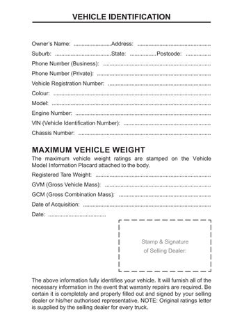
Date of Acquisition: ..................................................................................
Date: .....................................
Stamp & Signature of Selling Dealer:
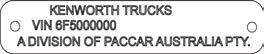
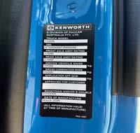
The above information fully identifies your vehicle. It will furnish all of the necessary information in the event that warranty repairs are required. Be certain it is completely and properly filled out and signed by your selling dealer or his/her authorised representative. NOTE: Original ratings letter is supplied by the selling dealer for every truck.
WELCOME TO THE KENWORTH FAMILY
We thank you for investing in your new Kenworth. Proudly engineered and built in Australia, this vehicle has been custom designed to meet your exacting standards and the specific requirements of your application. Advanced technology, pride in workmanship and a total commitment to quality have been combined to produce a truck that is unequalled.
Our network of dealers will support your Kenworth with the same quality and attention to detail that went into its manufacture. Anywhere in Australia, New Zealand and Papua New Guinea, support for your investment is only as far away as a phone call to your nearest Kenworth Dealer.
Australian Kenworth or DAF owners in need of emergency roadside assistance can simply call 1800 4 PACCAR (1800 4 722227). Trained operators are available 24-7 to connect you with your nearest PACCAR dealer for support.
Please take the time to read this handbook, as it contains information that will assist you in getting the most from your new Kenworth. We know it will provide many years of productive service, and we welcome you to the family of Kenworth owners.
This handbook illustrates and describes the operation of features or equipment which may be either standard or optional on this vehicle. This handbook may also include a description of features and equipment which are no longer available or were not ordered on this vehicle. Please disregard any illustrations or descriptions relating to features or equipment which are not on this vehicle.
PACCAR reserves the right to discontinue, change specifications, or change the design of its vehicles at any time without notice and without incurring any obligation.
The information contained in this handbook is proprietary to PACCAR. Reproduction, in whole or in part, by any means is strictly prohibited without prior written authorisation from PACCAR Inc.
INTRODUCTION
INTRODUCTION
ABOUT THIS HANDBOOK
Please take the time to get acquainted with your vehicle by reading this Driver’s Handbook. We recommend that you read and understand this handbook from beginning to end before you operate this equipment. Your handbook contains important information for the safe, efficient operation and service of your equipment. We urge you to become familiar with the handbook’s contents and use it as a ready reference. After you’ve read this handbook, it should be stored in the cab for convenient reference and remain with this truck when sold.
Your Kenworth may not have all the features or options mentioned in this manual. Therefore, you should pay careful attention to the instructions that relate to your vehicle. In addition, if your vehicle is equipped with special equipment or options not discussed in this handbook, consult your dealer or the manufacturer of the equipment. All information contained in this handbook is based on the latest production information available at the time of publication. Kenworth Trucks reserves the right to make changes at any time without notice. Your Kenworth dealer is only too pleased to go over the operation and controls of your new vehicle with you, and to explain any queries you may have.
Safety Messages and Notes
Be sure to read and follow all of the safety messages contained in this handbook. They are there for your protection and information. These messages can help you avoid injury to yourself, your passengers, and help prevent costly damage to the vehicle. Safety messages are recognised by highlighted background and a symbols (see page 21).
Do not ignore these safety messages.
This handbook consists of sections that describe the operation and care of the truck.
At the end of the handbook, there is a general alphabetical index, so that you can quickly locate what you are looking for.
We strongly recommend any system covered by State or Federal Regulations be inspected and serviced by an authorised Kenworth dealer or the component manufacturer’s service facility. This would apply particularly to safety, emission, lighting and noise control systems.
INTRODUCTION
Kenworth trucks are built to conform to all Australian Federal Standards and Regulations applicable at the time of manufacture. Kenworth Trucks cannot be held liable for any unapproved alterations to systems or components, certified or otherwise.
Some equipment described in this manual is optional and not included in the base specification of the vehicle. Kenworth Trucks undertake a continual product improvement program, therefore specifications and data contained in this handbook are subject to change without notice.
If there are any doubts about the safe operation of your Kenworth truck, contact your nearest authorised Kenworth dealer.
To ensure optimum performance and safe operation of your vehicle, Kenworth recommends it is regularly inspected and serviced by an authorised Kenworth dealer.
VEHICLE SAFETY
Do not drink alcohol and drive. Your reflexes, perceptions, and judgment can be affected by even a small amount of alcohol. You could have a serious or even fatal accident, if you drive after drinking. Do not drink and drive or ride with a driver who has been drinking. Failure to comply may result in death, personal injury, equipment or property damage.
Do not text and drive. Your reaction time, perceptions and judgment can be affected while texting or using any other form of mobile messaging while driving. Failure to comply may result in death, personal injury, equipment or property damage.
Make sure your vehicle is in top working condition before heading out on the road, it is the responsible driver’s duty to do so. Inspect the vehicle according to the Driver’s Check List beginning on page 26
Every new vehicle is designed to conform to all Australian Design Rules applicable at the time of manufacture. Even with these safety features, continued safe and reliable operation depends greatly upon regular vehicle maintenance. Follow the maintenance recommendations found in Maintenance on page 262. This will help preserve your investment.
Keep in mind that even a well maintained vehicle must be operated within the range of its mechanical capabilities and the limits of its load ratings. See the Weight Ratings label on the driver’s door opening.
Safe driving is only possible with proper concentration on the driving task. Keep distraction to a minimum to improve your concentration. Examples of distractions may include radio controls, GPS navigation controls, mobile telephone calls, cellular text messages, reading or reaching for something on the floor. Minimising your distractions will improve safe driving and will help avoid an accident involving death or personal injury.
Be aware of regulations that may prohibit the use of cellular telephones while driving. In addition to being an unsafe practice, it may be against local or federal ordinances to use cellular devices while operating the vehicle.
This manual is not a training manual. It cannot tell you everything you need to know about driving your vehicle. For that you need a good training program or truck driving school. If you have not been trained, get the proper training before you drive. Only qualified drivers should drive this vehicle.
A Special Word About Repairs
Do not attempt repair work without sufficient training, service manuals, and the correct tools. You could be killed or injured, or you could make your vehicle unsafe. Do only those tasks you are fully qualified to do.
Your dealer’s service center is the best place to have your vehicle repaired. You can find dealers all over the country with the equipment and trained personnel to get you back on the road quickly, and keep you there.
Your vehicle is a complex machine. Anyone attempting repairs on it needs good mechanical training and the correct tools. All warranty repairs must be performed by an authorised service dealer. If you aren’t an experienced technician, or don’t have the right equipment, leave all repairs to an authorised service dealer. They are the ones equipped to do the job safely and correctly.
INTRODUCTION
SAFETY VEHICLE OPERATION
For your safety, as well as that of those around you, be a responsible driver:
• Do not drive a vehicle under the influence of alcohol or drugs.
• Do not drive if you are tired, ill, or under emotional stress. Much has gone into the manufacturing of your Kenworth truck including advanced engineering techniques, rigid quality control and demanding inspections. These manufacturing processes will be enhanced by a safe driver – one who:
• Knows and understands how to operate the vehicle and all its controls.
• Maintains the vehicle properly.
• Uses driving skills wisely.
CHANGE OF ADDRESS/OWNERSHIP
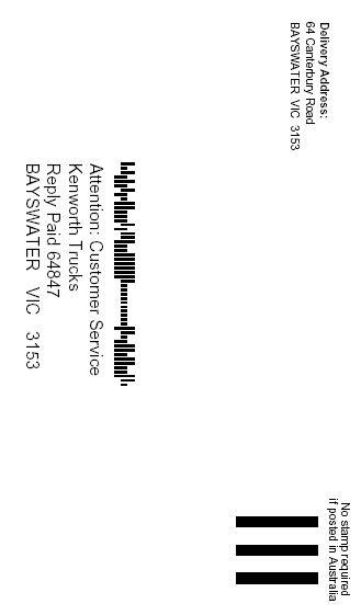
To assist Kenworth Trucks to keep vehicle records up to date. If you change any of your details (i.e. trading name or address) or subsequently sell this vehicle, please complete and return the pre-paid card provided opposite page to the reply paid address on the reverse. This notification is important even after expiration of the original vehicle warranty in case Kenworth need to contact you.
Alternatively, you can download the online form “Change of Address/ Ownership”, availble on Dealer net/PACCAR.net.
For any queries related to this topic, please contact your Regional Service Manager via email.
CHANGE OF ADDRESS/OWNERSHIP
Tear along perforation Tear along perforation Tear along perforation
Please assist Kenworth Trucks to keep vehicle records up to date. If you change any of your details (i.e. trading name or address) or subsequently sell this vehicle, please complete and return this form to the address on the reverse. This notification is important even after the original vehicle warranty in case Kenworth need to contact you.
SECTION 1
Warnings and Safety Regulations
WARNINGS AND SAFETY REGULATIONS
SAFETY SYMBOLS
Ignoring the safety instructions and warning can put health and safety at risk. It can also lead to serious damage to property and material.
WARNINGS
Text accompanied by this warning symbol indicates:
• Risk of personal Injury.
Example:
Do not carry additional fuel containers in your vehicle. Fuel containers, either full or empty, may leak or explode, and cause or feed a fire. Do not carry extra fuel containers. Even empty ones are dangerous. Failure to comply may result in death or personal injury.
CAUTIONS
Text accompanied by this caution symbol indicates:
• Risk to vehicle operation.
Example:
Continuing to operate your vehicle with insufficient oil pressure will cause serious engine damage. Failure to comply may result in equipment or property damage.
NOTES
Text accompanied by this note symbol indicates:
• Extra attention is required or extra information is provided.
Example:
Pumping the accelerator will not assist in starting the engine.
WARNINGS AND SAFETY REGULATIONS
PACCAR CONNECT
PACCAR Connect is a telematics platform that allows you to monitor driver and fleet performance, whenever you want and wherever you are. This intelligent and user-friendly platform will enable you to stay in control of your logistics processes, and to get the best out of your people and your vehicles.
Driver and fleet information is available via live tracking on desktop computer or mobile devices through easy-to-read and fully customisable dashboards and detailed reports that provide convenient and timely insights.
PACCAR Connect can also share vehicle data with third-party fleet management systems, allowing you the ability to integrate PACCAR vehicles into your business.
Features
A comprehensive range of features are available for both the driver and fleet operator as standard.
Tracking and Routing
• Live GPS tracking
• Geofencing
• Vehicle trip details and trip log reports
Driver Performance
• Harsh braking alert
• Harsh acceleration alert
• Moving and stationary over-revving alert
• Overspeed alert
• Over-idling alert
• Driver scorecard
Vehicle Safety
• Roll-over alert
• Impact alert
WARNINGS AND SAFETY REGULATIONS
Vehicle Performance
• Speed
• Brake count
• Gear changes
• Fuel usage
• Gross combination mass
• Engine RPM
• Live vehicle diagnostic trouble codes (DTC)
Vehicle Maintenance and Compliance
• Vehicle service maintenance logs and reminders
• Vehicle odometer readings
• Battery voltage level
• Engine hours
• Pre-trip vehicle inspections
Vehicle Security
• Know where your vehicles are, at all times
• Movement without ignition alert
• Movement from a designated area alert
SECTION 2
Vehicle Checks
VEHICLE CHECKS
DRIVER’S CHECKLIST
To keep your Kenworth truck in peak condition and maintain a high level of safety for you, your passengers and your load, make a thorough inspection every day before you drive. You will save maintenance time later, and the safety checks could help prevent a serious accident. You are not expected to become a professional technician. The purpose of your inspections is to find anything that might interfere with the safe and efficient transportation of yourself, any passengers and your load. If you do find something wrong and cannot fix it yourself, have an authorised Kenworth dealership repair your vehicle right away. The operations on the following pages are to be performed by the driver. Performing these checks and following the maintenance procedures in this handbook will help keep your Kenworth truck running properly.
DAILY CHECKS
1. Walk around truck, trailer(s), body and visually check for damage.
• Fuel Tank Mounting / Filler Caps in Place and secure / DEF cap in place
• Mud Flaps / Serviceable
2. Visual inspection of windows, none are broken and all are clean.
• Check glass for Cracks or Chips
3. Visual inspection of mirrors, none are broken and all are clean and functional.
• Check mirrors / Heated / Motorized Operation
4. Visual inspection of truck and trailer(s) lights: None are broken and all are clean and functional.
• Headlights - High & Low Beams
• Clearance Lights / Reflectors
• Roof outline lights
• Reversing / Load Lights
• Brake Lights
• Turn Lights
• Emergency Flashers
• License Plates, Permits & Mounting
• Road Lights
VEHICLE CHECKS
5. Visual inspection of wheel ends and under the vehicle for any fuel or oil leaks.
• Fuel Leaks
• Engine Oil / Fuel / Coolant
• Transmission Oil Leaks
• Front hubs seals and oil level
• Rear hubs seals
6. Visual inspection that tyres are inflated; are all wheel nuts in place and torqued.
• Cracks or Loose Wheel Lugs
• Irregular Wear / Air Leaks
• Tandem Mating / Tyre Clearance
• Tyre Pressure and Remaining Tread(Record Below)
• Record once per week
7. Drain service air tanks.
8. Visual/audible inspection for obvious air leaks.
9. Visual check of access steps and handles clean and secure.
10. Visual check of all trailer couplings are clean and undamaged (air, light, ABS/EBSS, tow hitch).
• Air Lines & connectors
• Trailer Light Line & Connectors
• Trailer ABS/EBSS Line & Connectors
11. Visual check of diesel fuel level.
12. Visual check of DEF level, if applicable.
13. Visual check of windscreen wipers and washers; Top up windscreen washer reservoir as required.
14. Test that electric horns and air horns operate.
15. Check that truck system air pressure build time is reasonable (Different configurations have specific values but should not exceed 15 seconds).
16. Visual check of engine oil level. Top up as required.
17. Visual check of engine coolant level. Top up as required.
18. Visual check of power steering oil level. Top up as required.
19. Visual check of engine fan and fan belts for damage.
20. Visual check of engine air cleaner restriction indicator.
VEHICLE CHECKS
21. Visual check of emergency triangles, fire extinguisher and other safety equipment.
22. Check operation of CB/UHF radios, telephone, data loggers, etc. (if fitted).
WEEKLY OPERATIONS
1. Battery - Check terminals.
2. Wheel Nuts - Are they all in place and torqued correctly? - Tighten if necessary. See Wheel Nut Torque page 307.
3. Other Controls and Wiring - Check for condition and adjustment.
4. Steering Components - Check pitman arm, draglink and power steering hoses for loose, broken or missing parts.
5. Other Engine Compartment Checks:
• Check condition and fastening of engine belt, hoses, clamps and radiator.
• Check the air cleaner, aftertreatment and exhaust pipes. Are they tight and secure?
• After Engine Warm-up: Looking & listening, check for leaks, all fluids, air system, air intake piping, exhaust for leaks.
EMERGENCY EQUIPMENT
It is good practice to carry an emergency equipment kit in your vehicle. If you have a roadside emergency you will be glad the following items are with you:
• Emergency light
• Emergency reflector triangles
• First aid kit
• Fire extinguisher
SECTION 3
Entering and leaving the cab
ENTERING AND LEAVING THE CABIN
WARNINGS:
DANGER
Do not ingest battery, Chemical Burn Hazard
This product contains a button battery. If the button battery is swallowed, it can cause severe internal burns in just 2 hours and can lead to death.
Keep new and used batteries away from children. If the battery compartment does not close securely, stop using the product and keep it away from children.
If you think batteries might have been swallowed or placed inside any part of the body, seek immediate medical attention.
Jumping out of the cab or getting into the cab without proper caution is dangerous. You could slip and fall, which could lead to death or personal injury. Keep steps clean. Clean any fuel, oil, or grease off the steps before entering the cab. Use the steps and grab handles provided, and always keep at least three points of contact between your hands and feet and the truck. Always face toward the vehicle when entering or exiting the cab and look where you are going.
If there is no deck plate, or if proper steps and grab handles are not provided, do not climb onto the area behind the cab, you may slip and cause personal injury.
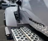
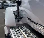
Do not step on vehicle components without anti-slip surfaces or use components not designed for entry-and-exit use. You could slip and fall, resulting in possible injury to yourself if you step onto a slippery surface.
Always reinstall the battery compartment cover (step) before entering the cab. Without the battery cover in place, you could slip and fall, resulting in possible injury to yourself.
A pivoting hood could hurt someone or be damaged itself. Before opening or closing the hood, be sure there are no people or objects in the way. Failure to stand in a position of safety can cause death or personal injury.
ENTERING AND LEAVING THE CABIN
Before opening or closing the hood, make sure your footing is secure and stable. Failure to do so may cause the hood to close uncontrollably which may result in death or personal injury.
Always ensure the hood hold-open latch is engaged to keep the hood fully open any time anyone gets under the hood for any reason. Failure to do so may cause the hood to close uncontrollably which may result in death or personal injury.
Before closing the hood, be sure the area is clear, no people or objects are in the way. Failure to do so may result in death or personal injury.
CAUTION:
A hood not latched securely could open during operation and cause vehicle damage. Be sure to latch the hood securely.
ENTERING AND LEAVING THE CABIN
VEHICLE ACCESS
DOOR LOCK AND KEYS
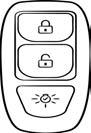
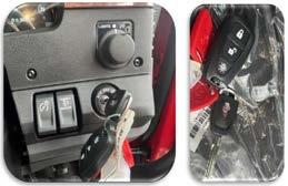
Doors can be locked from the inside via the switch on the door handle. Close the door, then depress the switch to lock. Doors automatically unlock when you open them from inside and can be locked from the outside with the key or the Remote Keyless Entry (RKE) button on the key fob.
Two keys with black bows are provided for the doors and ignition, and also have the KW ‘bug’ on both sides. Where your vehicle has a sleeper with tool compartments, two separate toolbox keys have a red bow.
To lock or unlock the doors from outside the cab:
• Insert the key in the door lock.
• Turn the key toward the truck’s rear to lock, and forward to unlock.
or
• Press the LOCK or UNLOCK button on key fob.
REMOTE KEYLESS ENTRY (RKE)
Kenworth Remote Keyless Entry system gives you added security and convenience for your Kenworth truck. This system will lock or unlock the driver’s and passenger’s doors with a key fob. It also activates the dome, door and step lights.
The key fob provides cab illumination during entry and exit of the vehicle.
Two key fobs are supplied, with up to four key fobs able to be used for any one vehicle.
REMOTE VERIFICATION
This function is optional and is enabled during the programming stage. When pressed, the LOCK button locks both doors.
To Lock and Unlock the Doors
1� To Unlock the Driver’s Door
a) Press the UNLOCK button once
b) Driver’s door unlocks
c) Door and dome lamps turn ON for 40 seconds (Door Closed)
ENTERING AND LEAVING THE CABIN
1� To Unlock the Passenger’s Door
a) Press the UNLOCK button again within 3 seconds
b) Passenger’s door unlocks
c) Door and dome lamps turn ON for 40 seconds (Door Closed).
2� To Lock Both Doors
a) Press the LOCK button once
b) Both doors lock
c) Door and dome lights turn ON for 2 seconds.
d) If Remote Verification is enabled, press the LOCK button again within 5 seconds to sound the horn. Repeated pressing of the LOCK button within a 5 second period causes the horn to sound and the interior lights to stay ON for a further 2 seconds.
3� Doors Open and Close
Door Action Key Position Door and Interior Lamps
Open the door OFF or ACC Lights turn ON and stay ON as long as door is left open for a maximum of 5 minutes
Close the door OFF or ACC Lights stay ON for approximately 10 seconds
Door in closed position Turn key to ON
KEY FOB
If lights are ON, lights go OFF immediately
The range of the Remote Keyless Entry system is approximately 10 metres. This will be reduced if it is operated close to other RF sources such as TV/Radio transmitters and cell towers.
ENTERING AND LEAVING THE CABIN
REMOTE KEY FOB IMAGE :
PROGRAMMING
The system is pre-programmed but may need to be reprogrammed if a key fob or receiver has been replaced. The programming procedure is in the Electronic Customised Maintenance Manual.
CAB AND FRAME ACCESS
SAFETY
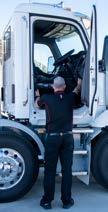
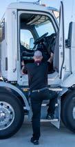
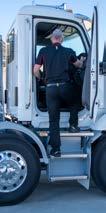
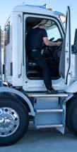
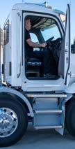
Be careful whenever you get into or out of your vehicle’s cab. Always maintain at least three points of contact with your hands on the grab handles and your feet on the steps.
ENTERING AND LEAVING THE CABIN
The following cab and frame entry/exit procedure recommendations were prepared with personal safety foremost in mind.
To help avoid personal injury due to a slip or fall:
• Always face the vehicle when accessing or leaving the cab or frame access area.
• Use three points of contact (two feet one hand; or one foot and two hands) to grip the steps or handholds whenever possible. Look where you are going, refer to page 37.
• DO NOT use the steering wheel, door handle or arm rest to pull yourself up into the cabin.
• Keep steps clean. Clean any fuel, oil or grease off the steps before entering the cab or accessing the deck plate. Use even more care when steps and handholds (or footwear) are wet or coated with ice, snow, mud, oil, fuel or grease.
• Mind your head when entering or leaving the cabin.
Do not step onto the surface of a fuel tank. A fuel tank is not a step. The tank surface can get very slippery, and you might not be able to prevent a fall. Use only the steps and handholds provided.
CLIMBING ONTO THE DECK PLATE
When you are climbing onto and off the deck plate, maintain at least three points of contact with your hands on the grab handles and your feet on the steps. Always face toward the vehicle when entering or exiting the cab and look where you are going. Failure to comply may result in death or personal injury.
When stepping onto a surface to enter the cab or access the deck plate, only use the steps and grab handles installed and designed for that purpose. Failure to use the proper steps and grab handles could cause a fall which may result in death or personal injury.
Keep steps clean. Clean any fuel, oil, or grease off the steps before entering the cab or accessing the deck plate. Stepping on a slippery surface can cause a fall which may result in death or personal injury.
Always reinstall steps before entering the cab or accessing the deck plate. Without steps in place you could slip and fall. Failure to comply may result in death or personal injury.
Any alteration (adding bulkheads, toolboxes, etc.) behind the cab that affects the utilisation of installed grab handles, deck plates, or frame access steps should comply with the original manufacturer’s design.
ENTERING AND LEAVING THE CABIN
Maintain three points of contact at all times. Using the vertical cab access grab rails and steps to climb up into a T320/A. Use the internal access handle to aid ingress and egress to the cabin. use the steering wheel or door closer/arm rest to pull yourself up into the cabin.
Maintain three points of contact at all times. Using the vertical cab access grab rails and steps to climb up into a T320/A. Use the internal access handle to aid ingress and egress to the cabin. DO NOT use the steering wheel or door closer/arm rest to pull yourself up into the cabin.
ENTERING AND LEAVING THE CABIN
ENGINE ACCESS
HOOD HOLD-DOWNS
Hood hold-downs keep a hood from opening unexpectedly. The images below show the hood latch positions in the T320 and T320A.
T320/A Latch Lock
T320/A Latch Unlock
ENTERING AND LEAVING THE CABIN
TILTING THE HOOD
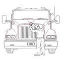
To open your hood, unlock the hood hold-downs by unlatching them. Put one or both hands on the top of the hood front. Tilt the hood forward by pulling from the top of the ‘KW’ emblem, pivoting on the foot placed on the bumper and using the foot on the ground for stability.
Keep pulling on the hood until you are certain that the hood hold-open device is engaged. When closing the hood, be sure that you maintain the same points of contact (top of hood and bumper) to control the movement of the hood as it closes.
Hood Safety Latch
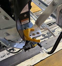
The hood is equipped with a hood safety latch. In order for the hood safety latch to become engaged, the vehicle hood must be fully open. Once the vehicle hood is fully open, the safety latch will automatically deploy and needs to be rotated in the anti-clockwise direction to permit hood closing.
Hood Safety Latch shown
ENTERING AND LEAVING THE CABIN
The safety latch is on the right-hand side hinge, as shown in the below photo. The latch deploys automatically when the hood is opened and must be rotated counterclockwise to allow the hood to close.
Hood Safety Latch in counter-clockwise position
SECTION 4
Driver environment
DRIVER ENVIRONMENT
WARNINGS:
Do not adjust the driver’s seat while the vehicle is moving. The seat could move unexpectedly and can cause the driver to lose control of the vehicle. After adjusting the seat, and before driving off, always check to ensure the seat is firmly latched in position.
Do not drive or ride with your seat backrest in the reclined position. You could be injured by sliding under the seatbelts in a collision.
Before driving or riding in the vehicle, ensure there is adequate head clearance at maximum upward seat travel. You could seriously injure your head or neck by bumping into the cab roof if clearance is not adequate.
Make all adjustments to the steering mechanism while the vehicle is stopped. Adjusting the Tilt/Telescoping Steering Wheel while the vehicle is in motion could cause loss of control. You wouldn’t be able to steer properly and could have an accident resulting in death or personal injury.
Use of excessive force to lock may create difficulties with further adjustments. The driver should verify that the gauges remain clearly visible, since the warning might not be active while making adjustments.
Under no circumstances should you attempt to service the steering wheel, clock spring or any of the electrical wiring in the multiplex system or any steering components (steering column, steering driveline or steering gear). Tampering with these components may result in an inoperable multiplex system.
DRIVER ENVIRONMENT
DO NOT operate the cruise control when operating on road surfaces with poor traction (wet, icy, or snow covered roads) or in heavy traffic. Accelerations caused by the normal operation of the cruise control could cause you to lose control of the vehicle resulting in an injury accident.
After you complete a turn, shut the system off by returning the lever to the ‘OFF’ (center) position. Failure to shut off a turn signal could confuse other drivers and could result in an injury or accident. An indicator light in the instrument panel will flash until the turn signal is turned off.
Clean blades regularly with a damp cloth to remove road film and wax build-up. Do not drive with worn or dirty wiper blades. They can reduce visibility, making driving hazardous which may lead to an injury or accident resulting in death or personal injury.
Do not carry loose objects in your cab. It can be dangerous. In a sudden stop, or even going over a bump in the road, they could fly through the air and strike you or your passenger. Carry any heavy objects such as luggage in the exterior storage compartment and close it securely.
Do not ignore a warning light or audible alarm. These signals tell you something is wrong with your vehicle. It could be a failure in an important system, such as the brakes, which could lead to an accident causing death or injury. Have the appropriate system checked immediately.
Do not park in an area where people are close by. You must keep combustibles at least 1.5m away from the exhaust outlet while the HEST lamp is illuminated. Failure to do so could result in serious injury.
DRIVER ENVIRONMENT
If the chassis is equipped with an Electronic Stability Control (ESC) and is modified (e.g. adding or removing an axle, converting from a truck to a tractor, converting from a tractor to a truck, changing the body, lengthening of the wheelbase and/or frame, relocating frame components, or modifying pneumatic or electrical ABS/ESC harnesses) the ESC must be evaluated by a qualified technician. If you have any questions, contact your authorised dealer. Failure to comply may result in property damage, personal injury, or death.
Do not park in an area of combustible vapors or materials. You must keep combustibles at least 1.5m away from the exhaust (outlet) stream as it exits the tail pipe while the HEST light is illuminated. Always park your vehicle outside. Failure to do so could ignite an explosion or harm bystanders which could result in serious injury.
If High exhaust system temperature lamp is on, temperature of the tailpipe, exhaust pipes, the SMA (SCR +DPF) and surrounding components including enclosures and steps becomes elevated during engine operation or any regeneration event and can cause serious burns to the skin. Allow adequate cooling time before approaching, working on or near any part of the exhaust system or surrounding components.
If the Stop Engine warning light illuminates, it means you have a serious engine system problem. This should be considered an emergency. You should stop the vehicle as safely as possible and turn OFF the ignition. The vehicle must be serviced and the problem corrected before driving again. Failure to comply may result in death, personal injury, equipment or property damage.
Do not carry additional fuel containers in your vehicle. Fuel containers, either full or empty, may leak, explode, and cause or feed a fire. Failure to comply may result in death or personal injury.
DRIVER ENVIRONMENT
Diesel fuel in the presence of an ignition source could cause an explosion. A mixture of gasoline or alcohol with diesel fuel increases this risk of explosion. DO NOT remove a fuel tank cap near an open flame. Use only the fuel and/or additives recommended for your engine. Failure to comply may result in death, personal injury, equipment or property damage.
Do not drive with visibility reduced by fog condensation or frost on the windscreen. Your view may be obscured which may result in death, personal injury, equipment or property damage. For clear visibility and safe driving it is extremely important for you to follow the instructions pertaining to the function and use of the ventilation/ heating and defogging/defrosting system. If in doubt, consult your dealer. Maximum heating output and fast defrosting can be obtained only after the engine has reached operating temperature.
Exhaust fumes from the engine contain carbon monoxide, a colourless and odourless gas. Do not breathe the engine exhaust gas. A poorly maintained, damaged or corroded exhaust system can allow carbon monoxide to enter the cab. Entry of carbon monoxide into the cab is also possible from other vehicles nearby. Failure to properly maintain your vehicle could cause carbon monoxide to enter the cab, resulting in death or personal injury.
Never idle your vehicle for prolonged periods of time if you sense that exhaust fumes are entering the cab. Investigate the cause of the fumes and correct it as soon as possible. If the vehicle must be driven under these conditions, drive only with the windows open. Failure to repair the source of the exhaust fumes may result in death, personal injury, equipment or property damage.
Adjust all mirrors before driving. Adjusting the mirrors while driving could cause you to take your eyes off the road which can result in an accident. Failure to do so could lead to serious injury or equipment damage.
DRIVER ENVIRONMENT
Use your Hazard Warning Light System any time you have to stop off the road or on the side of the road, day or night. A hard to see vehicle can result in an injury or accident. Another vehicle could run into you if you do not set your flashers and follow the placement of emergency signals.
Do not operate the Air Suspension Deflate Switch (Dump Valve) while driving. Sudden deflation while your vehicle is moving can affect handling and control and could lead to an accident. Use this switch only when your vehicle is not moving.
CAUTIONS:
Use Diesel Exhaust Fluid only. Failure to do so may damage components of the Diesel Particulate Filter (DPF).
Continued operation with the Air Filter Restriction Gauge reading 25in. H2O may cause damage to the engine. Inspect the filter and replace if necessary. Holes in the paper element render an air cleaner useless and may cause the Air Filter Restriction Gauge to give a false reading, even if the element is clogged. Replace the element if it is damaged.
Driving with a rear drive axle temperature of 130°C or more for an extended period of time can cause serious damage to axle bearings and seals. Have your axle lubrication checked if you notice a sign of overheating.
During extreme cold weather, do not blow hot defroster air onto cold windscreens. This could crack the glass. Turn the air flow control dial to defrost and adjust the fan speed accordingly while the engine warms. If the engine is already warm, move the temperature control dial to cool, then gradually increase the temperature when you see the windscreen is starting to warm up. Failure to comply may result in equipment damage.
Make sure the sleeper curtain is tied back. Raise the seat all the way up so the seat will tilt back and completely clear objects behind you. Make sure that the seat can move up and down freely after the backrest angle has been adjusted.
DRIVER ENVIRONMENT
Do not use antifreeze or engine coolant in the windscreen washer reservoir, damage to seals and other components will result.
If the electric pump is operated for a long period (more than 15 seconds) with a dry reservoir, the pump motor may be damaged.
Do not stay in the vehicle with the engine running or idling for more than 10 minutes with the vehicle’s heater and A/C ventilation system in RECIRC or at LOW FAN SPEED. Even with the ventilation system on, running the engine while parked or stopped for prolonged periods of time is not recommended.
The fan or equipment near it could be damaged if the fan turns on suddenly when you do not expect it. Keep all tools and equipment away from the fan.
Do not operate the engine fan in the MANUAL position for extended periods of time. The fan hub was designed for intermittent operation. Sustained operation will shorten the fan hub’s service life as well as reduce fuel economy.
NOTES:
The engine must be at operating temperature for maximum heating. If operating in AUTO mode, heating airflow is not allowed until the engine warms sufficiently to provide required coolant temperatures.
The A/C compressor may not engage when the outside temperature is below 1ºC.
Adjust the upper and lower lumbar supports before adjusting the side bolsters.
The ignition key must be turned to ON or ACC position for the turn signal lever to operate.
The ignition key must be turned to ON for the signal/switch to operate.
DRIVER ENVIRONMENT
The headlights must be ON for the high beam switch to operate. Continued pressing of the high beam flash will not keep the high beams on.
The ignition key must be turned to ON or ACC for the wiper/ washer switches to operate.
Clean the mirrors with a wet sponge or damp cloth only.
To access Favourites, scroll to the bottom. The view indicator will always stop at the Minimised View, then require an additional nudge downward to access Favourites.
The last used active profile, including any changes to that profile, will remain the profile until a new one is selected.
For more information about the stability control system installed on your vehicle, please refer to additional material supplied with this operator manual, included in your glove box informational packet.
For vehicles equipped with Lane Departure Warning, please refer to Lane Departure Warning Driver's Guide for additional information.
Some optional lights may illuminate even though your vehicle is not equipped with that particular feature.
The instrument cluster gauges may appear, if hidden from view, change brightness and change color to bring attention to a particular system.
Keep the engine exhaust system and the vehicle’s cab ventilation system properly maintained. It is recommended that the vehicle’s exhaust system and cab be inspected:
• By a competent technician
• Whenever a change is noticed in the sound of the exhaust system
• Whenever the exhaust system, underbody or cab is damaged
DRIVER ENVIRONMENT
This vehicle may be manufactured with different fuel systems and different draw tube locations. Because of this and the amount of road crown, it is recommended that you do not operate your vehicle with less than one-quarter of your truck's fuel capacity. Allowing the fuel level to go below one-quarter of capacity could result in the lack of fuel to keep the engine running. In addition, you will want to keep the fuel tanks at least half-full to reduce condensation of moisture in the tanks. This moisture can damage the engine.
The fan speed control dial must also be in the ON position to engage the A/C compressor. The A/C engages automatically when AUTO, Defrost or Floor/Defrost modes are selected.
To allow for proper operation of the vehicle ventilation system, keep the inlet grille at the base of the windscreen clear of snow, ice, leaves and other obstructions at all times.
When idling for short periods of time:
• Set the heating or cooling system to heat or A/C
• Set the fan to medium or high speed
• Set the controls to FRESH AIR
If you are required to idle your vehicle for long periods of time, install an auxiliary heater or automatic idle control. These auxiliary devices can reduce fuel consumption and save you money. If you are parked next to idling vehicles, move your vehicle or do not stay in your vehicle for prolonged periods of time.
The trailer brake is not to be used as a substitute for the service brakes. Using this brake frequently, instead of using the foot brake, will cause the trailer brakes to wear prematurely.
The Headlamp Switch is an ON or OFF switch. The panel lights are on full intensity during the day and go to dimmer mode when headlights are on.
The generic air accessory switch is designed by the original equipment manufacturer to reset when the ignition power is turned off. When ignition is turned off, this circuit will exhaust air pressure.
DRIVER ENVIRONMENT
CABIN
This section covers the Cab.
SEATS
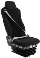
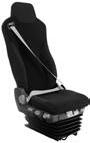
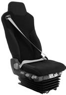
This section covers the operation and safe use of your Kenworth seats. For further information on features and adjustment of the seat, see the seat manufacturer’s Service and Operation information supplied with the vehicle.
1 Integrated 3-point seat belt system
2 Backrest angle adjustment
3 Integrated pneumatic system (IPS) dual stage air lumbar with lateral support
4 Air Height Adjustment
5 Adjustable vertical shock absorber
6 Suspension quick release
7 Seat rake adjustment
8 Seat cushion adjustment
9 Horizontal isolator
10 Seat slide adjustment
DRIVER ENVIRONMENT
SEAT ADJUSTMENT
Seat Position Adjustment
Backrest Angle Adjustment
Pull the lever to adjust the position of the complete seat. Once the desired position has been achieved, release the lever.
Pull up the locking lever to adjust the backrest angle. Once the desired angle has been achieved, release the lever.
DRIVER ENVIRONMENT
Seat Height Adjustment
Pull or push the height adjustment lever to move the seat up or down. The handle must be released to maintain the adjusted height.
Seat Vertical Shock Absorber Adjustment
Adjust the seat suspension characteristics with the vertical shock absorber adjustment switch. The seat suspension characteristics can be optimised in three positions.
DRIVER ENVIRONMENT
Seat Suspension Quick Release
Press the button downwards to drop the seat down to its lowest position. Press the top of the buttong to raise the seat back to its last saved height.
Seat Rake Adjustment
Pull the lever to adjust the rake angle of the complete seat. Once the desired angle has been achieved, release the lever.
Seat Cushion Adjustment
Pull the lever to adjust the seat cushion length. Once the desired length has been achieved, release the lever.
Lumbar Support Adjustment
2
1
DRIVER ENVIRONMENT
Use these switches to adjust the lumbar support of the backrest. The upper and lower lumbar support sections can be adjusted individually.
1. Lower lumbar support section (switch to the front)
2. Upper lumbar support section (central lumbar support switch)
Use the rearmost lumbar support switch to adjust the side bolsters of the backrest.
SAFETY RESTRAINT BELTS
Seatbelts have proven to be the single most effective means available for reducing the potential for either serious injury or death in motor vehicle accidents. Therefore, read the following instructions and always observe user warnings pertaining to seatbelts.
Too High on hips
DRIVER ENVIRONMENT
Lap & Shoulder Belt
The combination lap-shoulder belt is equipped with a locking mechanism. The system adjusts automatically to a person’s size and movements as long as the pull on the belt is slow. Hard braking or a collision locks the belt. The belt will also lock when vehicle is going up or down a steep hill or in a sharp curve.
Make sure all seatbelts are correctly adjusted before moving the vehicle. Adjustment is made by sliding the adjusting buckle either up or down the seatbelt until the belt is comfortable. Take care not to over tighten the belt by removing all of the slack.
Safety Belt Tips
• Anyone riding in your vehicle should wear a correctly adjusted seatbelt. A responsible operator sees to it that everyone in the vehicle rides safely and that means with a seatbelt.
• Do not wear a belt over rigid or breakable objects in or on your clothing, (for example eye glasses, pens, keys) as these may cause injury in an accident.
• Several layers of heavy clothing may interfere with proper positioning of belts and reduce the overall effectiveness of the system.
• Keep belt buckles free of any obstruction that may prevent secure locking.
• Cab or sleeper belts which have been damaged or worn because of cuts, tears, normal wear or excessive stretch forces from crashes must be replaced. They may not protect you if you have an accident.
• If belts show damage to any part of their assembly, such as webbing, bindings, buckles or retractors, they must be replaced.
• Do not allow seatbelts to become damaged by getting caught in the door or seat hardware, or by rubbing against sharp objects.
• The belts must be kept clean or the retractors may not work properly.
• Never bleach or dye seatbelts; chemicals can weaken them. Do, however, keep them clean by following the directions on the care label on the belts. Let them dry completely before allowing them to retract.
• Make sure the belt of the unoccupied passenger seat is fully wound up on its retractor, so the belt tongue is in its stowed position. This reduces the possibility of the tongue becoming a striking object in a sudden stop.
• Do not modify or disassemble the seatbelts in your vehicle.
DRIVER ENVIRONMENT
• If any seatbelt is not working properly, see your authorised Kenworth service dealer for repair or replacement.
Sleeper - Bunks and Restraints (UPO for T320)
For Kenworth cabs equipped with a sleeper, be sure to use the fitted restraint devices. Your vehicle may have belts which are over the bunk or cover the opening.
Be sure to stow away all loose belongings before you move your vehicle. Do not store objects on the bunks. They could cause serious damage or injury in an accident.
IGNITION KEY SWITCH
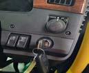
The ignition key switch (located to the right of the steering column) has four positions; ACC (Accessories), OFF, ON, and START.
ACC
ACC: With the key in this position you can play the radio, defrost mirrors or use other accessories.
OFF: In this position all accessories are OFF (except those listed below) and you can remove the key.
The following lights and accessories have power when the key is in the OFF position:
• Brake lights
• Emergency hazard flasher
• Interior and courtesy lamps (on doors)
• Electric horn
• Tail lights
• Marker lamps
• Headlights
• Radio station memory
• Instrument lights
• Auxiliary power
• Instrument panel memory settings
DRIVER ENVIRONMENT
In the OFF position, fuel is cut off by a solenoid valve.
ON: In the ON position all circuits are energised. A chime will sound initially and panel warning lights will light until the engine is started, and normal oil operating pressure is reached, chime will sound until air brake system pressure is above 4.96bar. In this position the ignition key cannot be removed.
START: Turn the key to this position to start your engine. Release the key after the engine has started. For complete engine starting procedures, see Operating The Engine on page 148
STEERING COLUMN AND CONTROLS
The steering column has controls for tilt/telescope, turn signal, wipers, engine brake and optional transmission controls.
The turn signal lever is mounted on the left side of the steering column. The lever controls several functions; turn signal, high beam and windscreen wiper control.
ADJUSTABLE STEERING COLUMN
Your truck is fitted with an adjustable Tilt/Telescoping steering column which is controlled by the easy access lever on the lower left hand side of the column housing.
• The tilt feature allows forward and rearward movement of the wheel.
• The telescoping feature allows you to adjust the height by moving the wheel up and down.
DRIVER ENVIRONMENT
Height and Tilt Adjustment:
To make these adjustments use the tilt/telescoping lever shown below.
• Push down and hold on the lever on left side of steering column.
• Adjust column height by pushing down or pulling up at the same time
• Raise lever to its fully locked position assuring proper locking.
Steering Column Locked
Steering Column Unlocked
STEERING WHEEL CONTROLS
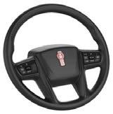
The steering wheel contains controls for commonly used functions so that the operator does not have to take their hands off of the steering wheel to operate. These controls are also used to interface with the display.
1 Left Switch Pod
2 Horn Pad
3 Right Switch Pod
DRIVER ENVIRONMENT
Left Switch Pod
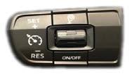
Switches on the left side of the horn pad manage the cruise control function. See Cruise Control on page 107. See button layout below.
1. Trip
Used to start a new trip. A total of 26 trips (A to Z) can be recorded. Holding down the trip button will reset all trips.
2. Cruise Control (CC) SET+
Used to set the cruise control speed or increase speed when cruise control is engaged (can be long pressed)
Cruise Control (CC) RES-
Used to ‘resume’ cruise control with the previous settings or decrease speed when cruise control is engaged (can be long pressed)
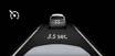
3. Toggle (only on trucks with ACC/Collision Mitigation) Adjusts the adaptive cruise control’s ‘follow’ distance
4. Cruise Control ON/OFF Turns the cruise control system on or off
Right Switch Pod
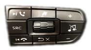
Switches on the right side of the horn pad control the infotainment and navigate and configure the digital display systems.
Infotainment Control
DRIVER ENVIRONMENT
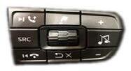
The infotainment system is controlled by the buttons on the left and right hand side of the right switch pod. See the image below for the infotainment button layout.
Controls
4 Previous / End Call
5 Media Source
6 Next Track / Call Answer
Digital Display Controls
The digital display is controlled by the buttons in the middle of the right switch pod.
Digital Display Controls
1. Shortcut
The shortcut button will access items that are configured in the settings.
2. Scroll Wheel
The Scroll Wheel is used to change Drive Views and navigate through menus on the digital display. Pressing down on the scroll wheel will select menu options or change settings when in the system menu.
3. Back/Cancel
Use the Back button to return to the previous menu, suppress a popup, or cancel a selection.
DRIVER ENVIRONMENT
Horn
To use the electric horn, press the pad in the center of the steering wheel, which is the standard location for electric horns. Your vehicle may be equipped with air horns. To operate, pull on the lanyard extending from the overhead console panel adjacent to the ‘A’ pillar.
TURN SIGNAL/HIGH BEAM SWITCH
The lever-action turn signal/high beam switch is located on the left side of the steering column.
Turn Signals
Turn Signal/High Beam Switch on Steering Column
• To signal a right turn, push the lever forward
• To signal a left turn, pull the lever back Each time the turn indicator is activated the audible warning emits a short click.
High Beam
• To switch your headlights to low or high beam, gently pull the turn signal lever toward the steering wheel until you hear the switch click and the beam changes. The blue indicator light in the instrument panel will illuminate when the high beam is being used.
• To return to previous beam; pull the lever towards the steering wheel again.
• The high beams can be momentarily flashed with or without the headlights being on. To flash the high beams, gently push the headlight lever away from the steering wheel to momentarily turn on the lights.
DRIVER ENVIRONMENT
WINDSCREEN WIPERS/WASHER
Your vehicle is equipped with a two-speed intermittent windscreen wiper system. The windscreen wiper system is integrated with the exterior lights so the low beam headlights will turn on when the windscreen wipers turn on.
To override this function, turn the headlights on and then off again and the low beams will turn off.
A seven position rotary wiper switch (located on the turn signal lever) operates the windscreen wipers and washer. Rotate the end of the turn signal lever to change the wiper mode.
Wiper/Washer on Steering Column
The first position after OFF is the intermittent No 1 cycle. The next positions are intermittent No’s 2, 3, and 4. The last two positions are wiper low speed and wiper high speed.
To Wash the Windscreen
Push the rotary wash/wipe outer knob in (towards steering column), hold for more than 1 second and then release. Hold the knob in to extend the washing cycle. After the lever is released, the wipers will shut off automatically or resume the wiper’s setting speed.
To activate the wipers for one swipe without activating the washer (‘mist’ function), push the wash/wipe outer knob in (towards the steering column) and release in less than 0.5 seconds. The wipers will perform a single swipe and then resume the wipers setting speed.
DRIVER ENVIRONMENT
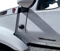
The washer bottle filler is located on the passenger’s side cowl panel. The washer bottle contains approximately 13 litres of water. Check the windscreen washing fluid level daily. If necessary, fill to top. See the image below for the location, which is just above the hood latch.
Windscreen Washer Cap Location
Clean all inside and outside windows regularly. Avoid running the wiper blades over a dry windscreen to prevent scratching the glass. Spray on washer fluid first. A scratched windscreen will reduce visibility.
CONTROLS ON RIGHT HAND SIDE OF THE STEERING COLUMN
The lever on the right hand side of the steering column will operate the engine brake for vehicles with manual transmissions. For detailed instruction see Engine Brake Operations on page 174.
DRIVER ENVIRONMENT
This vehicle may be equipped with an automated transmission. The lever on the right hand side of the steering column will operate the transmission functions in addition to operating the engine brake. For detailed instruction see Engine Brake Operations on page 174 and Transmission Controls on page 162
1. Transmission D - N - R Function
2. Up (+) and Down (-) Shift and Low Mode
3. Engine Brake and Max Mode
4. Manual (M)/Automatic (A) Mode Button
DRIVER ENVIRONMENT
MIRRORS
The complete mirror bracket can be folded back against the cab, and returns to its original position by folding the bracket back again.
KERB SIDE MIRROR
In addition the main mirror and the wide view mirror, there may also be a kerb mirror, providing the driver with a better view.
DRIVER ENVIRONMENT
Rotate the mirror up or down to get the desired view.
Electrically Adjustable Mirrors
For information about electrical mirror adjustment, see Door Mounted Controls page 116.
INTERIOR STORAGE COMPARTMENTS
There are a variety of interior storage compartments to store your personal supplies or small tools:
• Overhead storage compartments
• Sleeper storage compartments
• Centre console
• Map pocket/records holder, on front of rider’s seat base
• Door in passenger seat base
• Rear wall storage pocket
Appliances
If your vehicle has been fitted with an aftermarket television, or other appliance, be sure they are compatible with your vehicle’s electrical system. Secure them in the cab so they cannot come loose in a sudden stop.
DRIVER ENVIRONMENT
TOOLBOXES
Cabs with sleeper have additional storage or toolboxes, overloading these with heavy objects such as dogs and chains etc. will overload the cab suspension.
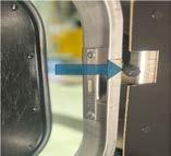
If you open the toolbox, you will find a latch that opens the upper bunk door from outside the truck.Latch looks similar to the one in the image below.
INSTRUMENT CLUSTER
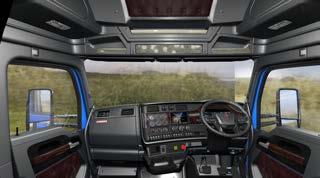
For information on using the dash and instrument cluster options, see the paragraphs that follow. Please remember that each vehicle is custom built. Your instrument panel may not look exactly like the one in the pictures that follow.
We have tried to describe the most common features and controls available. You can pick out the parts that apply to you and read them to be fully informed on how your particular vehicle operates.
DRIVER ENVIRONMENT
DASH LAYOUT
DRIVER ENVIRONMENT
The digital display is controlled by the buttons located in the middle of the right switch pod of the steering wheel. These buttons are used to select Drive View, navigate and select items in the Menu, and view Popup messages on the digital display. The shortcut button will access items that are configured in the settings, Shortcuts on page 83.
DRIVER ENVIRONMENT
Scroll Wheel
Use the Scroll Wheel to navigate through menus and press down to select menu options, change settings when in the menu, and switch between Views.
For example, press down and then scroll to access the clock menu. Then press down and scroll again to adjust the clock values.
Press down to select the menu: Press again to select the sub-menu:
Menu Example: Settings
Use the Scroll Wheel to scroll through the values then press down to select.
Menu Example Set Function
Back
Use the Back button to return to the previous menu, suppress a popup , or cancel a selection. Popups on page 98
DRIVER ENVIRONMENT
DIGITAL DISPLAY
The new digital display is the heart of the T320/A and brings together the separate individual gauges seen on previous models into one centralised unit.
The digital display will stay visible during all driving situations and in some parked situations. When the parking brake is set the following actions will wake the display, making it visible:
• Opening (or keeping open) the cab doors
• Using steering wheel switches
• Tapping the brake
• Turning the ignition switch to ON, ACC, or START
• Starting the engine.
If after 20 seconds none of these actions are taken, the display will dim to conserve power, but will awaken if any wake action is performed.
DRIVER ENVIRONMENT
DIGITAL DISPLAY SCREENS
SELECTING A VIEW
The instrument cluster has 5 views for the operator to use.
• Minimised View 1 w/o background.
• Minimised View 2 with background.
• Basic View.
• Enhanced View
• Favourites
o May be turned off and hence disabled
Each view is identified by a specific view indicator on the right side of the display area.
Name Icon Description
Minimised View 1
Minimised View 2
Basic View
The minimised view is the top view accessible by scrolling the steering wheel scroll wheel. The view is characterised by a single centre gauge of tachometer and speedometer without the background graphic.
It is similar to the minimised view but contains the background. In the pagination, it is the second view seen after the Minimised View.
The Basic View is characterised by the main centre gauge and the two side gauge groups without the outer gauges. The pagination is the second to last diamond in the pagination sequence.
DRIVER ENVIRONMENT
Name Icon
Expanded View
Description
The Enhanced View displays the maximum number of gauges. The pagination is indicated by the bottom diamond or circle in the pagination sequence.
Favourites View
View indicator with Favourites
Disabled (Minimised 1 shown)
The Favourites view is accessed by scrolling to the bottom to the enhanced view, and then pausing and scrolling down once more to access the Favourites view. Favourites may be disabled in the settings menu, which will cause the Star to be hidden.
4 screens selectable: Minimised 1, Minimised 2, Basic, and Expanded.
Transmission Gear Behaviour Display Icon in Dash
MODE ICON
Normal
C2
Low
Driver Selected Gear
Restriction
DESCRIPTION
In normal mode, "N" will be displayed in centre of gear. This is a default behaviour and no gear limit icon just the attained gear is shown.
In secondary mode, "C2" will be displayed at the bottom of the gear. This mode is activated by holding stalk up for 6 seconds.
In low mode, transmission is limited to 1st gear (or lowest available at current speed). You can upshift to cancel this mode.
I n DSGR mode, transmission will not shift above the selected gear. To change maximum gear tap upshift or downshift. Gear limit on dd (set to 6 in the picture) is applicable only with an Allison transmission,
Minimised View
DRIVER ENVIRONMENT
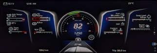
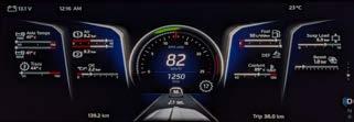
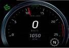
A combination speedometer and tachometer will show in the center of the Minimised View.
Minimised View with Adaptive Cruise Control (Option) 2
1. Optimal RPM Indicator (refer page 82)
2. Smart Tach®
3. Engine Speed
4. Transmission Gear
5. Adaptive Cruise Control
6. View Indicator
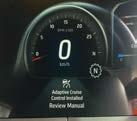
Adaptive Cruise Control Notification (option)
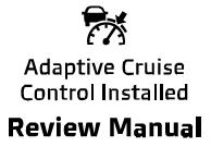
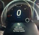
This indication at vehicle start means it is equipped with Adaptive Cruise Control (ACC) and Collision Mitigation. These features work together to improve driver safety and enhance the driving experience.
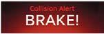
When Cruise Control is active, ACC will accelerate and slow the truck to maintain a chosen distance from a detected forward vehicle. Collision Mitigation will attempt to prevent a forward collision when advancing at speeds greater than 24 km/h. Please review the ACC section of this manual, prior to driving this vehicle.
DRIVER ENVIRONMENT
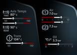
1. Gauges for Basic View and Enhanced View
2. Gauges for Enhanced View only
3. View Indicator
Basic View
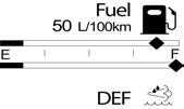
This view combines the instrumentation presented in Minimised View with gauges such as Fuel and DEF level.
Enhanced View
This view includes all the gauges present in the Basic View, adding gauges on the left and right in the display. Enhanced View is designated by the bottom icon in the View Indicator.
Favorites View
Vehicles with Favorites View will allow the operator to customise the arrangement of many of the gauges. Using the Favorites View requires the operator to Scroll to select the Minimised View. Once the Minimised view is showing, Scroll up once more to the star icon the View Indicator.
To disable Favorites View in the Digital Display, contact your authorised dealer. Vehicles with Favorites View enabled allow the operator to create a customised arrangement of all but centrally located gauges. To change the Favorites configuration, stop the truck, set the parking brake and
• Access Favorites via the Settings Sub-menu. OR
• Scroll to Favorites (represented by a star in the View Indicator) and press Select.
DRIVER ENVIRONMENT
ADDING FAVOURITES IN THE DIGITAL DISPLAY
Adding a Gauge to Favorites
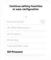
The truck must have the Parking Brake set to add a gauge. You must be in the Edit Your Favorites menu to perform this procedure. Adding a gauge requires that the gauge is not already assigned a location in Favorites View. If you want to move a gauge already assigned, you must first remove that gauge Removing a Gauge from Favorites on page 74
1� Scroll the list until you locate the desired gauge or compound gauge.
Edit Your Favorites (Center of Screen)
If the gauge you want to position is already present in the Favorites View (either as a single or compound gauge) it will not appear as a menu option.
2� Select to choose the gauge you want to position.
3� Scroll through the valid locations (this can include positions currently holding a gauge, which may be replaced) and target that position.
DRIVER ENVIRONMENT
If a position is not valid, the display will read “Not Available.”
Edit Your Favorites (Left-side of image)
1� Select to Add or Replace the gauge.
Navigate and Select “Save Configuration” when all gauges have been arranged. The Display will read “Your favorites configuration has been saved.” Press Back to exit Editing Favorites.
Removing a Gauge from Favorites
The Parking Brake must be set and at least one gauge must be in the Favorites View to remove a gauge.
The Speedometer/Tachometer, Fuel, and Air pressure gauges located at the Display center cannot be removed. If the gauge you want to remove is part of a multiple gauge group, the whole group must be removed.
1� Select “Remove Gauge.”
2� Scroll to highlight the gauge to be removed and Select.
Navigate and Select “Save Configuration” if this is the last change you want to make to Favorites View. The Display will read “Your favorites configuration has been saved.” Press Back to exit Editing Favorites.
DRIVER ENVIRONMENT
DRIVE, NEUTRAL, AND REVERSE INDICATOR
The drive, neutral, and reverse indicator reflects the shifter position of an automated transmission. Manual transmissions do not provide feedback to the display. Instead, the transmission shifter indicates the gear condition.
DNR Mode
Drive mode
Neutral mode
Reverse mode
Stalk Shifter Fault State
Stalk Shifter Start-up State
Kenworth
DRIVER ENVIRONMENT
MENU OVERVIEW DIGITAL DISPLAY
SYSTEM MENU
The following menus are available to the driver by pressing the scroll wheel (right hand pod):
• Notifications
• Trip Summary
• Settings
• Truck Information
These menus are only accessible when:
1. The Parking Brake is set
2. All active popup messages are viewed and suppressed
These menus allow the operator to configure settings on the vehicle. To navigate through the system menu, use the digital display controls on the right hand pod.
Notifications
Notifications display system messages related to the condition of your vehicle. It displays the following items:
• Active messages
• Systems Check
Trip Summary
Presents a summary of details such as fuel economy and distance of the trip, collected during the main trip and/or sub-trips. These details will be collected until the trip is reset, or the max trip distance (99,999.9 km for main, 9,999.9 km for sub-trips) is reached.
Settings
Settings allows the operator to customise the display. The following are some of the parameters that can be adjusted:
DRIVER ENVIRONMENT
Truck Information
Truck information stores specifications and data about the vehicle. The following sub-menus are available under the truck information menu.
• Chassis
• Engine
• Anti-lock Brake System
• Transmission
• Transmission Oil Level
• Remote Station Interlocks
• Adaptive Cruise Control (ACC) option
• Power Take Off (PTO) option
General
• Time
• Format
• Automatic Time
• Units and Language
• Features
• Dark Cabin
• Digital RPM (optional)
• Windshield Wiper Interlock
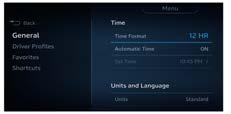
Time
This menu allows the operator to customise the clock.
• Automatic Time (optional) When enabled, trucks with Automatic Time will receive time zone appropriate data.
• 24-Hour Time
Choose between 12 or a 24 hour format. AM or PM (A or P) shall only be displayed in 12-hour time format.
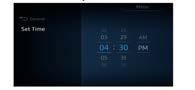
• Set Time
Set Time is available when Automatic Time isn’t enabled. Set the clock to indicate your local time.
Units and Language
• Units
Use this setting to change the units of measurement between Standard, Metric (Bar), and Metric (PSI).
DRIVER ENVIRONMENT
• Language Use this setting to change the language.
Features
Features allows the operator to enable optional features on the vehicle to customise their experience.
• Shutdown Timer (Optional)
Shutdown Timers are used to automatically turn off the engine after a specified period of idling or inactivity. Refer page 154 for detailed explanation.
• Detailed ACC (Optional)
Adaptive Cruise Control feature when active, accelerates and slows the vehicle to maintain a chosen distance from a detected vehicle. Refer page 197 for detailed explanation.
• Digital RPM
Provides a digital numeric readout of the engine speed in the speedometer.
• Windshield Wiper Interlock
This activates the headlights when the windshield wipers are turned on.
• Dark Cabin
Dark Cabin prevents cab interior lights from turning on when a cab door is opened.
• Night Mode
Night mode dims the display automatically at night or when reversing. Brightness can be adjusted via the dash dimmer switch.
Driver Profiles
This feature saves customisations made as a Driver Profile. Turning Driver Profiles ON for the first time will load current customisations into Driver Profile 1 and make it the active profile. The profile can be changed in this menu.
The active Driver Profile can also be changed after setting the park brake and then pressing Back. (The ignition key may need to be cycled back to OFF and then ON to access the Driver Profiles Settings) Changes to Driver Profile will be auto-saved while making customisations. They will not be lost when turning the feature off.
DRIVER ENVIRONMENT
Choosing the Active Driver Profile
Press Back when the parking brake is set to change the active Driver Profile.
Shortcuts
Use the Shortcuts option to assign one of the following features to the Shortcut button.
• Dark Cabin – Toggles Dark Cabin On/Off.
• Digital RPM – Provides a numeric read-out of RPM within the speedometer.
• Favourites – Selects the Favourites View on the Display.
DRIVE SUMMARY
The Drive Summary presents information about the most recent leg of travel and is shown when the ignition key is turned to “off.” The Drive Summary consists of:
• Critical and Non-critical Issues (see Systems Check)
• Shut Down Timer (if active) (see Shut Down Timer)
• Three customer-selected reports (i.e. Idle Time, Fuel Economy)
The Drive Summary collects information since the last time the engine was off for at least two hours. When insufficient information has been collected, Drive Summary will show dashes for the monitored component or report. Reports can be changed at your local dealership.
DRIVER ENVIRONMENT
WARNINGS
WARNING SYMBOLS
Guide to the Warning Symbols
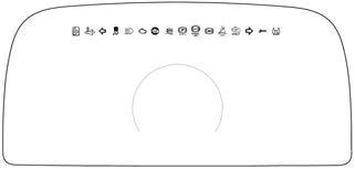
The warning lights and audible alarm may indicate a system malfunction. Check the lights frequently, and respond promptly as soon as you see one go on. These lights could save you from a serious accident. Additionally, gauges may become visible, may change colours, or may change brightness to raise awareness to the operator.
When multiple warning symbols are shown on the instrument cluster, they will appear at first and then minimise. When minimised they will be represented in the active warnings area of the display. A triangle represents that a warning is registered and a diamond represents a check message.
Check messages are provided to give the operator additional information regarding systems that require attention due to a system malfunction and/or operating conditions that may hinder safe and proper performance for the vehicle. The system will emit a chime to alert the operator that a message is appearing on the cluster. Some messages can be managed by the operator while others may require an authorised dealer repair.
The following is a list of Warning Light/Indicator Symbols that appear in the instrument cluster and Digital Display:
Axle, Stability Control
Calculates the driver’s intended path of travel from wheel speed and steering angle sensors, then compares calculations to the actual direction of travel. The system uses individual wheel brakes to re-adjust the path of the vehicle.
• The Stability Control Icon (ESC or Electronic Stability Control) illuminates during the Bulb Check when the ignition is turned ON. It turns off after a few seconds if no system problems are detected. If a problem is detected, the ESC Warning lamp will turn on and stay on.
• Illuminates when the ESC system is regulating individual wheel brakes to correct the vehicle’s direction of travel. (Refer to Advanced ABS with Stability Control for more information)
DRIVER ENVIRONMENT
Axle, Traction Control
Monitors wheel speed for poor traction. If a wheel begins to slip due to poor traction, it may reduce engine power or apply brakes in an effort to regain traction.Refer page 196 for detailed information.
• Illuminates during the Bulb Check when the ignition is turned ON. It turns off after a few seconds if no system problems are detected. If an ATC problem is detected, the ATC warning light will turn on and stay on.
• Illuminates when the ATC is regulating wheel spin and turns off after the traction control event has ended.
• Flashes continuously when the ATC/Deep Snow & Mud switch is turned on, indicating that this feature is active.
Brakes, Anti-lock Brake System
Illuminates during the bulb check. Have the ABS system checked by an authorised dealer if the ABS Warning Lamp stays on for more than 3 seconds.
• Illuminates during normal operating conditions to indicate a problem with the ABS system.
• Illuminates when a problem exists with Automatic Traction Control (ATC).
Brake,
Park Brake
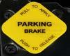
Illuminates in the status indicator when parking brakes are applied.
Brakes, Low Air / Trailer Low Air
Illuminates when system air pressure falls below 4.96bar (72 psi).
Trailer low air warning light illuminates the same warning in dash when trailer supply/emergency line pressure drops below 4.5bar (65 psi).
DRIVER ENVIRONMENT
Brakes, Trailer Anti-lock Brake System
Illuminates during the bulb check and the tractor/truck is connected with a ABS equipped trailer. Illuminates during normal operating conditions to indicate a problem with the Trailer ABS System. This should be checked by an authorised dealer as soon as possible.
Cruise Control
This indicator shows the operator which Cruise Control function is currently enabled or active. This includes
• Cruise Control
• Adaptive Cruise Control (optional)
• Variable Road Speed Limiter (optional)
When a Cruise Control function is enabled, a white indicator will appear. When a Cruise Control function has been activated, the indicator will change from white to green. For more information on use of the various Cruise Control functions, see Cruise Control, Adaptive Cruise Control, and Variable Road Speed Limiter.
Differential, Inter-Axle Lock
Illuminates when the inter-axle differential switch is ON thus locking the inter-axle differential. This powers the forward rear and the rear rear differentials equally. When the switch is turned off (inter-axle differential unlocked) the engine power is allowed to flow to any of the four drive tyres based on the differential effect (mostly to the forward rear differential). This feature is standard on all tandem axles.
Tipper Truck, Body Up
Illuminates when Truck Tipper Body is up.
Tipper Truck, Gate
DRIVER ENVIRONMENT
Illuminates when Truck Tipper gate is open.
Diesel Particulate Filter (DPF) Warning Light
This icon and related message will appear when the DPF needs to be regenerated and then also during the regeneration cycle. This may also appear if the system is attempting to automatically regenerate while the vehicle is in Power Take Off operation mode.
Engine aftertreatment system includes a diesel particulate filter and DPF warning light.
Emissions, High Exhaust System Temperature
Illuminates when the exhaust gas temperature and exhaust components become extremely hot.
Emissions, Malfunction Indicator Light
Illuminates when an engine emissions failure has occurred. The vehicle can be safely driven but should be serviced to correct the problem. The situation should not be considered an emergency. In some cases, the Malfunction Indicator Light will activate in conjunction with the High Exhaust Temperature, Diesel Particulate Filter (DPF), and Diesel Exhaust Fluid (DEF) Warning Lights.
Engine, Check Engine
Illuminates when a non emissions related problem exists, but the vehicle can still be safely driven. Vehicle should be serviced to correct the problem but the situation should not be considered an emergency.
DRIVER ENVIRONMENT
Engine, Low Coolant Level
Illuminates with an audible alarm indicating critically low coolant level. The vehicle must be serviced to correct the problem but the situation should not be considered an emergency.
Engine, Retarder (Brake)
Illuminates when the engine retarder (compression brake or exhaust brake) switch is turned on.
Engine, Stop Engine
Illuminates an audible alarm tone will sound when a major engine system problem exists.
Engine, Wait-to-start Light
Illuminates when the engine needs time before starting. It will illuminate at key ON and stay on for up to 30 seconds. Wait for the light to turn off before turning the key to start the engine.
This may occur if the starter is too hot and needs to cool down or if the engine grid heater is warming up.
Driving Lights
Illuminates when the driving light is on.
Radar Blindness
Illuminates when the AEB Radar system is in fault or blocked.
Emissions, Engine Derate
DRIVER ENVIRONMENT
Illuminates when the emission related fault is detected.
Lights, High Beam
Illuminates when the high beams are on.
Lane Departure Warning (LDW)
Illuminates when LDW system is not able to track the vehicle’s position within the lane.
Camera Blindness
Illuminates when the AEB Camera system is in fault or blocked.
Seat Belt Fasten
Illuminates when the ignition key is turned on as a reminder to fasten your seat belt.
Batteries - Low Voltage Disconnect (LVD) - +
If your vehicle is equipped with a Low Voltage Disconnect (LVD) feature, the LVD module is integrated into the main load center.
DRIVER ENVIRONMENT
Transmission, Auxiliary
Illuminates to indicate auxiliary transmission is in neutral.
Transmission, Check
Illuminates when transmission has recorded a fault code.
Transmission Service Indicator
Illuminates when transmission has identified a service is required.
Turn Signal, Left
Blinks when the left turn signal or the hazard light function is operating.
Turn Signal, Right
Blinks when the right turn signal or the hazard light function is operating
Advanced Emergency Braking Disable (Optional)
Vehicles equipped with this optional switch will disable the Advanced Emergency Braking system, upon key cycle, the feature will re-enable. The feature may also be re-enabled by toggling the switch again while disabled. The switch will not affect any of the Adaptive Cruise Control warnings.
DRIVER ENVIRONMENT
Bulb Check
When the ignition switch is turned ON multiple warning icons will be displayed in a sequence to test each warning light indicator. The total sequence should take no more than 10 seconds to complete. Have your instrumentation system checked by a qualified service technician if does not successfully complete.
Audible Warnings
The audible alarm will sound in conjunction with most warning lights or popup notifications. These events include but are not limited to headlight on, fifth wheel, stop engine, primary/secondary air, and driver door open warnings.
Optional Icons
Additional icons may be operational depending on individual vehicle specifications.
GAUGES
Major Gauges
Vehicle and engine speed are presented at the center of the display only in km/h.
Speedometer
The speedometer is a primary vehicle gauge that displays the road speed of the vehicle. The data is displayed at the centre of the digital display.
Some of the highlights of the new concept for the digitally-displayed speedometer are:
• Engine RPM digital readout
• Resolution of 1 km/h
DRIVER ENVIRONMENT
Tachometer
Tachometer is a gauge that measure the rotation speed of the engine. The data displays at the centre of the digital display. Some of the highlights of the digitally-displayed tachometer are:
• Revolutions Per Minute (rpm) scale adjustability
• Over-speed zone (also known as red zone) adjustability
• 10 rpm resolution
The tachometer also supports the following functions:
• Optimal Engine Speed Indicator
This function displays a green bar just below the most fuelefficient engine speed range for the vehicle. The driver’s general goal should be to select a gear that keeps the tachometer needle positioned over the green light as much as possible during steady state driving.
• Smart Tach
For a manual, automated (in manual mode) or automatic (in manual mode) transmission, the Smart Tach will identify what the engine speed range will be upon a transmission gear upshift or downshift.
• PTO
The PTO light will be active when the PTO in enabled.
• Engine Over Speed Warning
An audible sound when the engine speed has exceeded the over-speed threshold.
DRIVER ENVIRONMENT
DRIVER ENVIRONMENT
Minor Gauges
Gauges allow the operator to monitor the status of vehicle functions and will alert the operator if a function is either out of parameters or in the warning state.
Gauges are located on the Display. Gauge layout can be customised in the Favorites view or based on vehicle factory configuration. Some may appear as a single or as a part of a compound gauge.
Diesel Exhaust Fluid (DEF)
The diesel exhaust fluid gauge shows the approximate amount of DEF fluid in the DEF tank.
DEF Level Gauge
Besides empty and full, the gauge also indicates 1/4, 1/2, and 3/4 of total capacity. DEF fluid is required to meet certain emission requirements. A warning icon and popup message will appear when the DEF level is low. Do not allow your DEF tank to remain empty. Please refer to your emission supplemental manual for more details about DEF fluid.
Fuel Level
DRIVER ENVIRONMENT
Fuel Level Gauge
The Fuel gauge(s) indicate the fuel level.
OPTIONAL GAUGES
Introduction
Listed here are gauges that may or may not be on your dashboard or the center instrument cluster. For vehicles with a telematic navigation screen, optional gauges will be part of the screen functions. Refer to the navigation system supplement for further details about its functions and how it works. Some vehicles may have optional analog gauges installed at the factory in place of the navigation screen.
Fuel Filter Restriction Pressure
This gauge tells you the condition of the fuel filter by indicating the restriction from the fuel filter to the fuel pump. Replace the filter with an approved filter only. Do not substitute the wrong micron element.
Air Filter Restriction Indicator or Gauge
This gauge indicates the condition of the engine air cleaner and is measured by inches of water (H2O). A clean filter should register approximately 10in. H2O or below (may vary with system design) and a filter whose life is over will register approximately 25in. H2O.
DRIVER ENVIRONMENT
Engine, Oil Pressure
It is important to maintain oil pressure within acceptable limits. If oil pressure drops below the minimum bar a red warning light in the gauge will turn on, the Stop Engine light will come on and an audible alarm will sound.
Engine, Oil Temperature
The Engine Oil Temperature gauge indicates the engine oil temperature. If the oil temperature exceeds the maximum limits, a red warning light in the gauge will turn on.
Turbo Boost Gauge
Your Turbo Boost Gauge indicates the power your engine is putting out by showing the amount of turbo boost. If the pressure indicated by your turbo boost gauge goes down, there may be something wrong with your engine. Have it checked by an authorised service technician.
Fuel Pressure Gauge
Your vehicle may also have a fuel pressure gauge.
Transmission Temperature Gauge
Your Transmission Temperature Gauge indicates the temperature of the oil in your transmission. Watch this gauge to know when your transmission is overheating. If it is, have it checked by an authorised service technician.
Maximum transmission temperature may vary, depending upon the transmission and type of lubricant.
DRIVER ENVIRONMENT
Drive Axle Temperature Gauge (Forward and Rear)
These gauges indicate the temperature of the lubricant in your vehicle’s axle(s). These temperatures will vary with the kind of load you are carrying and the driving conditions you encounter. Maximum axle temperature may vary, depending upon the axle and type of lubricant. Very high temperatures signal a need to have your axle(s) lubrication checked.
Depending on the vehicle configuration, there may be a drive axle temperature gauge for more than just the forward and rear drive. The icon will have an ‘X’ over the representative axle to indicate which axle the temperature is being displayed in the gauge.
Suspension Load Air Pressure 2
The Suspension Load Air Pressure gauge indicates the amount of air pressure in the air suspension air bags.
The gauge indicates the air pressure in the left hand side
(passenger’s side) air bags. The 2 gauge indicates the air pressure in the right hand side (driver’s side) air bags.
Prime Mover Brake Application Air Pressure
The Prime Mover Brake Application Air Pressure gauge indicates the amount of air pressure applied to the prime mover brakes.
Transmission Oil Temperature, Auxiliary
The Auxiliary Transmission Oil Temperature gauge indicates the temperature of the oil in the auxiliary transmission. Do not exceed maximum oil temperature of 148°C.
DRIVER ENVIRONMENT
NOTIFICATIONS ON THE DIGITAL DISPLAY
POPUPS
Popup: Red Oil Temp
A Popup displays information from the vehicle computer. These warnings include either a Red, Amber or White background colour. Certain types of popups are indicated by the Warning Indicator shown on the digital display. Multiple Popups will appear in the display as a stack of messages. Suppressible Popups are those that will move out of the stack when driving. All are suppressible when the Parking Brake is set. The Menu will not be accessible until all Popups have been Suppressed.
Viewing and Suppressing Popups
Viewing Multiple Popups
A Popup can be read and Suppressed by pressing the Scroll Wheel. Some situations may require pressing Back instead. For example, the following image is suppressed by pressing the Scroll Wheel (noted with the arrow down) OR by pressing the Back (indicated with the X mark below the roller).
Message not suppressible
If multiple popups are present the number of popups will be displayed as shown below.
DRIVER ENVIRONMENT
Case Scroll Wheel Icon (upper)
Driving popup, Suppressible.
Example:
If there is more than one popup in the queue then the scroll wheel icon with arrow will appear as shown.
Back/Delete Icon (lower)
Shows the X below the scroll wheel. Using the lower button will suppress and move onto the next popup.
Suppressing Popups
Whilst driving or parked some popups may be suppressed, please see table below for details. Case
If there is more than one popup in the queue shows the arrow over scroll wheel icon. –same as above.
Shows nothing below the scroll wheel. Using the lower button will move onto the next popup (just like the scroll wheel).
Parked, all popups become suppressible.
Example:
Shows the X over scroll wheel. Pushing suppresses.
Shows X below the scroll wheel. Pushing suppresses.
DRIVER ENVIRONMENT
TELLTALES ON THE DIGITAL DISPLAY
TELLTALES & INDICATORS
Indicators provide a visual relationship with the name of the notification to make it easier and faster to identify a function. Indicators act as telltales and inform the driver when a vehicle system is in use, gauge values are out of range, or a malfunction in a system is occurring.
Locations of indicators on the digital display is shown below.
Physical Telltales
There are 16 physical telltales that will always appear across the top of the display, they are a physical lamp.
Dedicated Telltales
Dedicated Telltales always appear in the same location throughout the screen. Some are visible only when active, but most signify that the monitored component requires operator attention.
DRIVER ENVIRONMENT Dynamic Telltales
These dynamic telltales appear on the display in the rows indicated. A dynamic telltale communicates the status of a monitored component, which may require the operator to respond or take action.
DRIVER ENVIRONMENT
Battery Telltale
The Battery Voltage indicator shows the battery icon, voltage, and the state of charge. The state of charge can be turned off in the settings menu. The battery icon will be replaced with the Low Voltage Disconnect (LVD) icon when Low Voltage Disconnect is active. The battery icon is grey when operating normally, but changes to amber to indicate a low voltage condition and red to indicate a high or very low voltage condition.
Clock
The clock can be displayed in a 12-hour or 24-hour format. Clock settings can be altered in the Settings Sub-menu.
Position Lamp and/or Dipped Beam Headlamp Telltale
Displays when Position Lamp and/or Dipped Beam Headlamp is in use. Not illuminated when Daytime Running Lights are active.
Active Warnings Indicator
Red or amber popups are counted and the total is displayed by the active warning indicator. In addition, these counts are also presented in
• Systems Check
• The Notifications Sub-menu
• A Drive Summary
The numbers may change without user interaction if individual warnings are intermittent, time based, self-correcting, or the situation is rectified.
Outside Air Temperature
Outside Air Temperature monitors the ambient temperature outside the truck. The display will alert the driver to high and low temperature conditions. When the outside temperate approaches freezing (2°C) an icon will appear next to the temperature (snowflake for freezing and thermometer for high) and a chime will sound.
The system’s unit of measure (Celsius or Fahrenheit) can be changed in the Settings Sub-menu. The outside air temperature display uses a sensor (located at the bottom of the driver’s side mirror assembly) to measure outside air temperature only. It is not capable of displaying the temperature of the road surface on either the temperature display or the snowflake icon. Additionally, the outside air temperature reading may be affected by exposure to direct sunlight.
DRIVER ENVIRONMENT
Diesel Particulate Filter (DPF) Status
The Diesel Particulate Filter indicator shows the soot load percentage. This indicator will change colours as the soot load increases. (see Guide to the Warnings Symbols).
Sub-trip Odometer
The Trip Odometer can be split into smaller segments called Sub-trips. Start a Sub-trip by pressing the Trip marker button on the steering wheel. The maximum distance that the sub-trip will show is 9,999.9 at which point it will start over at zero. When it maxes out, the current subtrip ends and begins a new one. Sub-trip information is also found in the settings menu Trip Summary on page 76.
DRIVER ENVIRONMENT
Trip Odometer
The Trip Odometer shows how far the vehicle has gone traveled since last it was reset. The maximum distance that can be shown on the Trip Odometer is 99,999.9 at which point the operator needs to reset. Press the Trip marker button to set. Press and hold the Trip marker button to reset (Item 1 in following image).
The operator may also use the trip summary to view the same information Trip Summary on page 80
Driver Profile Indicator
The number following the icon indicates which driver is active when Driver Profiles are enabled. For information on Driver Profiles, Choosing the Active Driver Profile on page 82.
Odometer
The odometer displays the total distance your vehicle has traveled. The maximum distance that can be shown on the odometer is 9,999,999.9. The odometer will roll over to zero if maximum mileage is achieved.
Engine Hours
Engine hours will display the total number of hours the engine has been operated. The maximum hours that can be shown are 99,999.9 before the counter rolls over to zero.
DRIVER ENVIRONMENT
Engine Brake Indicator
The engine brake telltale consists of two parts.
1. Engine brake status
2. Engine brake level
Engine Brake Status
The engine brake icon is white when enabled and green when active. When OFF, neither indicator is shown.
*System activated with stalk shifter in OFF position. If the stalk is not OFF, the stalk position is always shown.
Engine Brake Level
White bars indicate the level setting and the grey bars indicate an available, inactive brake setting. The number of white bars mirrors stalk engine brake position.
DRIVER ENVIRONMENT
Manual Transmissions
Automated Transmissions
Max Mode
Vehicles fitted with an automated transmission will have the ability to access a third mode known as Max Mode. This applies 100% engine braking and also engages the low gear on the transmission for an additional braking force.
DRIVER ENVIRONMENT
Cruise Control
The cruise control light will be active when cruise control is enabled. Below are a list of icons displayed in the cruise control display area.
Description
Cruise control OFF
Display
Cruise control unavailable
Cruise control enabled, resume not available
Cruise control enabled, resume available Cruise control engaged
DRIVER ENVIRONMENT
SYSTEMS CHECK
The systems check evaluates each monitored system and displays its progress for the operator. The Systems Check will appear when the Exterior Lighting Self-Test is activated, refer page 98, or when viewing the Notifications sub-menu. It is recommended to do a system check before each drive.
Systems Check can be interrupted at any time by:
• Pressing Select by pressing down on the scroll wheel in the right hand steering wheel switch pod
• Switching the Exterior Lighting Self-Test switch on the dash to OFF
• Turning the ignition key to OFF
• Releasing the Parking Brake
Depending on the installed options, the digital display will do a check on the following systems (depending on the optional features):
1. Battery
2. Engine
3. Transmission
4. Exhaust system
5. DEF system
6. Fuel system
7. Engine oil
8. Coolant
9. Air system
*If equipped
10. ABS system
11. Brake system
12. Axles
13. Air filter
14. Exterior lights
15. Driver rewards*
16. Driver performance assistant*
At the end of a system check, the display shows a resume and provides an option to view more details about the faults found during system check.
DRIVER ENVIRONMENT
CAB HVAC CONTROLS
Fan Control Dial
MAX Defrost Button
Outside Air/ Recirculation Air Button
AUTO Mode Button
DRIVER ENVIRONMENT
Introduction
Your vehicle’s heating and air conditioning system operates in three distinct modes; manual, automatic and maximum defrost. Each mode provides the driver with the greatest level of comfort and convenience while maintaining the flexibility of traditional systems. The recommended mode for all conditions that do not require windscreen defrosting is the automatic mode as detailed on page 111. This mode is capable of maintaining cab comfort under various driving conditions without driver interaction.
The cab heater and A/C controls are located together towards the left hand side of the dash.
Manual Control Mode
The manual mode is the default mode when the heating and air conditioning system is turned on. The fan speed, air temperature and air outlets are selected using the dials on the controller.
Adjusting the settings:
1. To adjust the fan speed, turn the fan control dial clockwise to increase speed or counter-clockwise to decrease speed. Setting the fan dial to ‘0’ turns the HVAC system off.
2. To adjust the temperature setting, turn the temperature control dial to the desired temperature. The system automatically adjusts the outlet air temperature to achieve the desired cab temperature.
3. To adjust the air distribution, turn the air distribution dial to the desired position as indicated by the graphics.
The temperature of the air from the vents will fluctuate as the vehicle works to achieve the chosen cab temperature. Note that in manual mode the system does not engage the A/C compressor automatically. To engage the air conditioning, press the button inside the temperature dial. To engage recirculation of cab air, press the button inside the fan speed dial.
DRIVER ENVIRONMENT
Automatic Control Mode
Your vehicle’s air conditioning system is equipped with an automatic button that provides complete cab climate control without driver intervention. When selected, the system will manipulate the air distribution, air temperature, fan speed, A/C compressor, and cab air recirculation to achieve the comfort level selected on the temperature dial. The button that enables automatic mode is labeled AUTO. The system will remain in automatic mode until the driver adjusts the dials on the control.
AUTO
Auto Control Mode Button
Adjust the temperature knob and the system will respond to obtain the selected comfort level as quickly as possible.
Using the automatic mode:
1. Turn on HVAC by rotating fan speed control clockwise.
2. To engage automatic mode, press the AUTO button.
3. To adjust cab temperature, rotate the temperature dial to the desired temperature. The system automatically adjusts to achieve the desired cab temperature.
The system will achieve the comfort level associated with the selected temperature on the temperature dial. Therefore, depending on the specific environmental conditions, the air temperature can be slightly higher or lower than the set point. This is a normal function of the AUTO mode and is not to be mistaken for a malfunctioning system.
The AUTO function uses a sunlight sensor to measure the amount of sunlight entering the cab. This sensor is located at the base of the windscreen on the passenger’s side of the dashboard. Do not block this sensor.
DRIVER ENVIRONMENT
Partial Automatic
During AUTO mode the operator may override any setting and operate in a partial automatic mode. This can be done via the dials and/or buttons on the HVAC control. In the partial automatic mode, the AUTO button indicator will cease to be illuminated. Instead, the indicator of the adjusted setting will illuminate.
For example, if the driver adjusts the fan dial while in AUTO mode, the fan dial indicator will illuminate and fan speed will adjust to the setting of the dial. However, the temperature and air outlet settings will continue to function automatically. Similarly, if the driver adjusts the air distribution setting while in AUTO mode, the air distribution dial indicator will illuminate and the distribution will adjust to the setting of the dial. The fan and temperature settings will continue to function automatically.
Economy Function
An economy function is also available in partial automatic mode. In this mode the system will operate in AUTO mode without the use of the A/C compressor.
The operator may select economy by initiating AUTO mode and then pressing the A/C button to disengage the compressor. The indicators for A/C compressor and AUTO mode do not illuminate while operating in economy mode.
MAX Defrost Mode
The heating and air conditioning system provides for one touch windscreen defrosting. Certain driving conditions will cause fog or ice to form on the windscreen. By pressing the MAX defrost button, the HVAC system will automatically adjust the blower speed, air temperature and air outlet distribution to maximise clearing of the windscreen. The system will remain in this mode until the driver presses the button again or adjusts the dials.
Note that the air temperature in MAX defrost mode will be set to the warmest temperature setting. This setting helps to clear the windscreen of ice and fog more quickly. Outside air mode and A/C compressor are also active to maximise performance.
MAX
Maximum Defrost Button
DRIVER ENVIRONMENT
BUTTONS AND DIALS
Fan Speed Control Dial
The fan speed is adjusted by rotating the dial clockwise to increase speed or counter clockwise to decrease speed. Setting the fan dial to ‘O’ turns the HVAC system off.
Fan Speed Adjustment
The source of air entering the cab can be set to either outside air or recirculation air using the button inside the fan speed control dial. Outside air mode is automatically selected when any of the defrost modes are selected.
Air Distribution Dial
The mode of air distribution inside the cab is set using the air distribution dial. Five icons on the dial indicate the primary mode options. The driver may also select a secondary mode in between the primary modes indicated by points on the dial. Airflow is provided to the side windows in all modes.
*Defrost and demister vents
*Automatically engages outside air and A/C compressor.
Outside Air/Recirculation Air Button
Dash Vents
Dash and Floor Vents
Floor Vents Floor and *Defrost Vents
DRIVER ENVIRONMENT
Temperature Control Dial
The cab temperature is set using the temperature control dial. The operating range is 16°C to 28°C. Adjustments of 1° increments.
22
Temperature Control Set Point
The button inside the temperature control dial engages the A/C compressor. When activated the indicator on the button will illuminate. During AUTO mode, the A/C button indicator will remain illuminated at all times even though the compressor may be cycling.
OPERATING TIPS
Defrosting and Defogging the Windscreen
The cab windscreen and side windows can be cleared of ice and fog in two ways. The first is to use the MAX defrost mode (See MAX Defrost Section on page 112). The second is to manually adjust the air distribution dial to the defrost position.
Manual Windscreen Defrosting/Defogging
The manual defrost/defogging mode differs from the MAX defrost mode by allowing the driver to select an air temperature other than full heat. This allows the driver to maintain a constant cab temperature while defrosting the windscreen. Note however that performance may be reduced.
1. Adjust the fan speed to high by rotating the fan control dial clockwise.
2. Set the air distribution dial to the defrost mode setting. This automatically engages the outside air and A/C compressor.
3. Adjust the temperature dial to add heat as needed. For maximum performance, adjust the temperature to maximum heat by rotating the temperature dial clockwise.
The driver may also use the floor/defrost setting on the air control dial to maintain a clear windscreen while providing heat to the floor. This setting may be helpful in conditions where the windscreen re-fogs. To increase the effectiveness of the defroster, engage the A/C compressor.
DRIVER ENVIRONMENT
For Maximum Cooling
1. Adjust the fan speed to high by rotating the fan control dial clockwise.
2. Set the air distribution dial to the dash setting.
3. Adjust the air temperature to maximum cool by rotating the temperature dial counter clockwise.
4. Engage the A/C compressor by pressing the air conditioner button.
5. Set the air source to recirculation mode by pressing the outside air/recirculation air button. The button indicator light should be illuminated.
For Maximum Heating
1. Adjust the fan speed to high by rotating the fan control dial clockwise.
2. Set the air distribution dial to the floor setting.
3. Adjust the air temperature to maximum heat by rotating the temperature dial clockwise.
Air Dehumidification
The HVAC system can be used to reduce the humidity level of the cab and clear fog from the windscreen.
1. Adjust fan speed to the desired airflow setting.
2. Engage the A/C compressor by pressing the air conditioner button.
3. Set the air source to outside air mode by pressing the outside air/recirculation air button. The button indicator light should NOT be illuminated.
Cab Air Distribution
Equal distribution of air is important in maintaining a constant cab interior temperature. For best performance, all vents should remain open to allow the AUTO mode to function properly.
To maintain the selected cab temperature the AUTO mode may provide an air temperature from the vents that differs from the temperature set point. To ensure proper operation, it is recommended the driver redirects the air instead of adjusting the temperature set point or closing the vent. The system may have difficulties in obtaining the desired cabin temperature if the temperature setting is repeatedly changed.
DRIVER ENVIRONMENT
Outside Air/Recirculation Air
Selecting air recirculation mode completely isolates the cab interior from the outside air. This mode is helpful in preventing dust, pollen, and odours from entering the cab. Additionally, recirculation mode can reduce the amount of time needed to cool down the vehicle while in maximum cool down. Note this mode may increase fogging on the windscreen. A coarse air filter is provided for recirculation air and is located behind the fuse panel on the passenger side. The outside air mode provides for 100% outside air into the cab. This mode is helpful with windscreen defogging. A pleated air filter located under the hood provides filtration for dust, pollen and debris.
DOOR MOUNTED CONTROLS
Introduction
Your vehicle is equipped with power mirrors, the mirror controls will be located on the driver side door pad. Mirrors can be adjusted in 4 directions.
To provide good visibility, adjust the mirror so the side of your vehicle appears in the inboard part of the mirror.
Mirror Heat Switch
Your vehicle is equipped with standard heated mirrors. Mirror heat is controlled by the mirror heat switch button, which is part of the mirror switch module located on the driver side door pad.
DRIVER ENVIRONMENT
Mirror Adjustment Switch
The directional controls for both mirrors are located near the top front of the driver side door trim pad.
1. Move the mirror selector switch (3) to the right or left from the neutral center position to select the desired mirror for adjustment.
2. Depress the mirror directional control pad (2) in one of its four arrow directions to adjust the mirror in/out or up/down.
3. After mirror adjustments have been completed, return the mirror selector switch (3) back to the center (neutral) position to prevent unintentional adjustments to the mirrors.
Mirror Selector Switch
If the mirrors require adjustment, use this switch to select either right or left hand mirror.
Power Window Switch
Power window rocker switches are located on the door pads. Depress the switch to open the window or pull up on the switch to close the window. Release the switch to stop window movement. The drivers side window has an express down feature. Pushing on the switch all the way down and hold it for approximately 1 second until the switch bumps will activate the express down feature. Release the button and the window will continue to open until it is completely open.
Power Door Lock Switches
Power door lock rocker switches are located at the front of the interior door handle levers on the door trim. To lock or unlock both cab doors, depress any door lock switch that displays a closed or open padlock symbol, respectively, on the switch face.
DRIVER ENVIRONMENT
DASH SWITCHES
This vehicle will have a wide variety of switch controlled equipment, however, may not have every switch identified in this section of the operator manual.
Some air device switches on the dash may require that the vehicle either be at a specific speed, parking brakes set or another device to be on or off for the air device to operate.
The instrument display will display information regarding what needs to change in order for the air device to operate as expected.
Alternator and NEED Isolation Switch
Alternator and NEED (Non-essential Electrical Device) Isolation switch is used in some fuel haul and dangerous goods applications. When activated, this combined switch disables the alternator and at the same time isolates non-essential electrical devices in the vehicle like AVN/ Infotainment unit, CB radios, Power sockets and Sleeper accessories etc.
Axle, Differential Lock - Tridrive
Tridrives will have these axle differential lock controls and are 2 separate switches. FRONT will control the forward rear and REAR will control the center/rear-rear axle differential. In addition, a vehicle with Tridrive will have an interaxle differential lock switch.
Axle - Diff-Lock - Dual
Turn switch on to engage Front and Rear Axle Diff Lock.
Axle - Diff-Lock - Forward Rear
Turn switch on to engage Forward Rear Axle Diff Lock.
Axle - Diff-Lock - Rear Rear
DRIVER ENVIRONMENT
Turn switch on to engage Rear Rear Axle Diff Lock.
Axle - Diff-Lock - Single Rear
Turn switch on to engage Single Rear Axle Diff Lock.
Axle - Inter-Axle Differential Locked (Tandem)
Turn switch on to engage Inter-Axle on to Differential Lock.
Axle - Two Speed
If equipped, the two speed axle switch allows you to select axle high and low ranges. The low range (Off) provides maximum torque for operating off-highway. The high range (On) is a faster ratio for highway speeds. This switch does not require ignition power to maintain the desired switch setting.
Backup Mute Alarm (Optional)
Turn switch on to mute reverse backup alarm.
Fifth wheel release (Optional)
Turn switch on to release the trailer.
DRIVER ENVIRONMENT
Brakes, Parking Brake Valve
Pull yellow knob to activate parking brakes. See Parking Brake Valve on page 182
Brakes, Trailer Air Supply Valve
The red octagonal knob controls the air supply to the trailer. With both knobs pushed IN, air is now being supplied to both the trailer and the truck spring brakes; all brakes are released.
Brakes, Trailer Hand
This dash mounted switch provides air pressure to apply the trailer brakes only. It operates independently of the foot treadle valve.
To operate the trailer brake hand valve, press the lever down to engage the Trailer Hand Brakes. Release the lever so that it can return to its original position to release the Trailer Hand Brakes, independent of the truck brakes.
For trucks delivered in Australia and New Zealand, this valve is selfreturning. When pressure is removed from the valve lever, it will return to the OFF position.
Cab Dimmer Switch
This switch is used to alter the brightness of the instrument panel lights.
Engine - Fan Override
DRIVER ENVIRONMENT
The engine fan switch allows you to control the engine fan manually or automatically.
Engine - Remote Throttle
Turn switch on to activate Remote Throttle Control.
Generic - Air Accessory
Provides accessory air to the end of frame connection when end of frame connection switch is turned on.
Generic - Spare
Turn switch on to power customer installed accessory.
Lane Departure Warning Disable (Option)
Vehicles equipped with this optional switch will disable the audible and visual Lane Departure Warning for 15 minutes after which time, or upon key cycle, the feature will re-enable. The feature may also be re-enabled by toggling the switch again while disabled. The switch will not affect any of the Adaptive Cruise Control warnings. If equipped, the Lane Keeping Assist feature will also be disabled while the Lane Departure Warning feature is disabled.
DRIVER ENVIRONMENT
Lights - Auxiliary
AUX
Turn switch on for Auxiliary Lights.
Lights - Beacon
Turn switch on for Beacon Light(s).
Lights - Dome Lights (Interior)
A two-position switch, located on the dome light, controls each dome light. In addition, the dome lights can be switched on or off with the dash-mounted switch.
Lights - Exterior Lights Self Test
This switch will engage a program which will illuminate exterior lights for the operator to verify functionality. This feature allows the operator to verify and inspect exterior lighting operation typically performed during a pre-trip inspection. When the feature is engaged, via a switch on the dash, it will illuminate the:
• Hazard/turn signals
• Low & high beam headlights
• First set of fog lights
• Stop/brake lights
After turning these lights off, the system will resume testing the first set of lights. The light test will eventually stop on its own. The operator may interrupt the test by turning the vehicle off or pressing the switch a second time while the test is running. The operator can verify the functionality of the lights by visibly watching the lights from outside the vehicle during the test or can read the instrument cluster for any faults
displayed that are lighting related.
DRIVER ENVIRONMENT
To start the Exterior Light Self Test feature:
1. Park the vehicle and set the parking brakes.
2. Insert the key into the ignition and turn the key to the ON position. Allow the vehicle to run through bulb check.
3. Press the momentary switch on the dash to start the Exterior Light Self Test.
Lights - Flood
Turn switch on for cab mounted Flood Lights.
Lights - Flood (Spare)
Turn switch on for trailer mounted Flood Lights.
Lights - Fog
Turn switch on for Fog Lights.
Lights - Hazard Warning
With the switch in the ON position, the emergency flasher makes all four turn signals (front and rear) flash simultaneously. The flasher works independently of the ignition switch. You should always use the flasher the vehicle is disabled or parked under emergency conditions.
DRIVER ENVIRONMENT
Lights - Headlight and Parking Lights
PTurn switch on for park/marker lights and headlights. When the headlights are ON, side, and tail lights are also on. When the headlights are on, the instrument lights including Smart Wheel, side and tail lamps are also on. This switch also controls the park lights.
Headlights will turn on if the windshield wipers are turned on. Manually turning the headlights on and then off will override this function until the next time the vehicle is turned on.
Lights - Spot
Turn switch on for Spot Light.
Power Take-off (PTO)
Turn switch on to engage PTO. Your vehicle may be equipped with a dash mounted switch that controls PTO engagement/disengagement.
When the operator activates the switch for the PTO, the status indicator lamp (located on the switch) will immediately illuminate even though PTO engagement may not have occurred.
If the PTO is engaged and the operator turns the switch OFF, the PTO status indicator lamp (located on the switch) will go out immediately even though PTO disengagement may not have occurred.
Pressurised Bell Housing
Turn switch on to pressurise bell housing.
Axle Lift, Single Tag
DRIVER ENVIRONMENT
Turn the switch on to inflate the lift axle suspension airbags. This raises the lift axle, transferring weight off the undriven axle onto the driven axles, increasing downward force and improving traction (commonly used on muddy work sites)
Suspension - Dump
Turn switch on to deflate Suspension Air Bags. This switch does not require ignition power to maintain the desired switch setting.
Traction Control
Momentarily push switch in to disengage Traction Control (TC).
Transmission - Auxiliary Transmission
Turn switch on to shift the Auxiliary Transmission.
SECTION 5
Coupling and Uncoupling
COUPLING AND UNCOUPLING
WARNINGS:
Do not exceed the specified load rating. Overloading can result in loss of vehicle control and personal injury, either by causing component failures or by affecting vehicle handling. Exceeding load ratings can also shorten the service life of the vehicle.
An unevenly distributed load or a load too heavy over one axle can affect the braking and handling of your vehicle, which could result in an accident. Even if your load is under the legal limits, be sure it is distributed evenly.
Ensure that all fifth wheel maintenance, adjustments and rebuilding are done only by a qualified technician. An improperly maintained fifth wheel can cause a trailer to separate from a truck. This could lead to an injury or accident and damage to property.
Where fitted, do not grease Teflon fifth wheel wear plates.
Do not operate the Air Suspension Deflate Switch (Dump Valve) while driving. Sudden deflation while your vehicle is moving can affect handling and control and could lead to an accident. Use this switch only when your vehicle is not moving.
Do not drive with ruptured air springs. The air loss can cause the spring brakes to apply. This allows your brakes to drag and may burn up the linings, which could lead to an injury or accident. Do not continue to operate the vehicle in this condition.
COUPLING AND UNCOUPLING
CAUTION:
Do not deflate the rear suspension before unlocking the fifth wheel. Deflating the rear suspension before unlocking the fifth wheel could cause difficulty during uncoupling and result in damage to the fifth wheel and kingpin.
NOTES:
Operating the release handle and unlocking the fifth wheel will depend on the fifth wheel manufacturer.
Do not drive prime mover free of trailer.
The fifth wheel will not unlock unless the vehicle is stopped and the parking brake is set. In this situation, a red-colored popup appears, informing the operator that 5th wheel release is not available and to set the parking brake. This will require restarting this procedure.
The plate must be lifted up slightly to relieve weight on the bracket while applying grease.
Operating a vehicle with air suspension bags either overinflated or underinflated may cause damage to driveline components. If a vehicle must be operated under such conditions, do not exceed 7km/h. The vehicle will automatically protect itself from damage and inform the driver if it is not safe to engage Air Suspension Dump or if the switch has been left on and has automatically been disengaged, these limits can be adjusted by a PACCAR dealer.
COUPLING AND UNCOUPLING
VEHICLE LOADING
Compare your vehicle’s load capacity with the total load you are carrying. If adjustments need to be made, make them. Do not drive an overloaded vehicle. If you are overloaded or your load has shifted, your vehicle may be unsafe to drive.
Gross Vehicle Mass (GVM) is the maximum allowable total mass of a fully loaded motor vehicle, consisting of the tare mass (mass of the vehicle) plus the load including occupants and fuel.
Gross Combination Mass (GCM) is when a vehicle is towing one or more trailers, the GCM is the total mass of the motor vehicle plus any, and all trailers including load, occupants and fuel.
The components of your vehicle are designed to provide satisfactory service if the vehicle is not loaded in excess of either the gross vehicle mass rating (GVM) and/or gross combination mass rating (GCM) and/or the maximum front and rear gross axle weight ratings.
FIFTH WHEEL
HOW TO RELEASE THE KINGPIN MANUALLY
To release the kingpin and separate prime mover from trailer
1. Position the prime mover and trailer in a straight line on firm, level ground.
2. Apply both the prime mover and trailer parking brakes.
3. Exit cab and lower the trailer landing gear.
4. Disconnect brake air and electric lines from trailer, and secure lines.
5. Unlock the fifth wheel release handle if necessary, then unlock the fifth wheel.
6. Return to cab and release prime mover parking brake.
7. Ease prime mover forward enough for the kingpin to clear the fifth wheel (about 30 to 45cm).
8. If the prime mover has a rear air suspension, deflate (dump) the rear suspension enough so that the fifth wheel will smoothly separate from the trailer.
9. Ease prime mover forward, clearing the trailer.
10. If the rear suspension was deflated, return rear suspension to its normal height.
COUPLING AND UNCOUPLING
HOOK-UP
To lock the fifth wheel around the kingpin:
1. Ensure trailer brakes are locked and the landing gear is down.
2. Back the prime mover fifth wheel into the trailer kingpin to engage and lock.
3. Pull the prime mover forward to ensure the kingpin has been locked in place.
4. Set the prime mover parking brake.
5. Connect the prime mover brake air and electric lines to the trailer. Conduct a pre-trip inspection prior to releasing the brakes, raising the landing gear, and driving the vehicle.
After connecting your truck to the trailer, always inspect the jaws to be sure they have locked on the kingpin before you drive the vehicle. Use the trailer hand piece to check that trailer kingpin and 5th wheel jaws are fully engaged.
REMOTE ACTIVATED 5TH WHEEL RELEASE PROCEDURE
1. Apply both the prime mover and trailer parking brakes.
2. Lower the landing gear.
3. Disconnect the prime mover brake air and electric lines from the trailer.
4. Push up and HOLD the 5th Wheel Release switch on the dash for at least 3 second to release the 5th wheel. A countdown timer popup will appear on the display, and the unlock symbol on the 5th Wheel Release switch will illuminate. The popup will inform the operator when to release the switch.
5. Release the switch. The unlock symbol on the 5th Wheel Release switch will turn off.
6. Ease prime mover forward enough for the kingpin to clear the fifth wheel (about 30 to 45cm).
7. If the prime mover has a rear air suspension, deflate (dump) the rear suspension enough so that the fifth wheel will smoothly separate from the trailer.
8. Ease prime mover forward, clearing the trailer.
9. If the rear suspension was deflated, return rear suspension to its normal height.
COUPLING AND UNCOUPLING
FIFTH WHEEL LUBRICATION
Refer to manufacturer’s instructions relating to fifth wheel lubrication guidelines.
Frequently operate and lubricate movable or sliding fifth wheels to prevent corrosion.
Both the fifth wheel plate and the slide tracks (if a slider) should be cleaned and lubricated periodically to ensure smooth turning and sliding action. Failure to keep these surfaces lubricated can lead to frame and/ or driveline damage.
Apply a water-resistant lithium base grease to the trailer contact surface of the fifth wheel. Apply same to the bearing surface of the support bracket through the grease fittings on the side of the fifth wheel plate.
AIR SUSPENSION
Air Suspension Height/Air Pressure
Your vehicle may have an air suspension and a deflation switch which allows the air in the suspension to be exhausted using a switch on the dash. The normal purpose of this feature is to allow you to lower the vehicle for loading. On prime movers, the deflate switch allows you to lower the fifth wheel to slide under a trailer.
Driving with Deflated Air Springs
If an air spring ruptures, there will be enough air pressure to drive the vehicle to a safe stop off the highway to investigate the problem.
Do not tamper with the height adjustment valves on your rear air suspension. The height is factory-set for optimum performance. Consult an authorised Kenworth dealer if the ride height requires adjustment.
Suspension Air Pressure Gauge
The Suspension Air Pressure gauges (optional virtual gauges) indicate the amount of air pressure in the air suspension springs in bar (100 kPa). Air pressure in the spring is related to the rear axle load. The greater the rear axle load, the greater the air pressure in the air bags. Therefore, the air pressure displayed will vary, depending on the rear axle load.
SECTION 6
Starting and Driving
STARTING AND DRIVING
WARNINGS:
Do not carry additional fuel containers in your vehicle. Fuel containers, either full or empty, may leak or explode and cause or feed a fire.
Do not remove a fuel tank cap near an open flame. Fuel vapours may be hot and combustible and can cause an explosion or fire. Failure to comply may result in death, personal injury, equipment or property damage.
Never refuel while engine is idling. Shut down a vehicle before refuelling, this can allow air to enter the fuel system resulting in a possible shutdown.
Trucks with SCR and equipped with a battery isolation switch require the driver to wait for at least 120 seconds after turning OFF the ignition before switching OFF the battery isolation switch. This is to allow the EAS system to purge any remaining DEF from the DEF lines. Shutting off the battery isolation switch whilst the engine is running or without waiting the required 120 seconds may cause DEF to be trapped in the DEF lines. This could lead to a blockage of the lines and cause serious damage to the EAS system.
Never idle your vehicle for prolonged periods of time if you sense that exhaust fumes are entering the cab. Investigate the cause of the fumes and correct it as soon as possible. If the vehicle must be driven under these conditions, drive only with the windows open. Failure to repair the source of the exhaust fumes may result in death, personal injury, equipment or property damage.
Always use first gear or a low speed range to start the vehicle in motion. The use of a higher gear or speed range forces undue strain on the engine, clutch and other transmission components, and may cause damage.
STARTING AND DRIVING
On automated transmissions there is no Park position, so you will need to apply the parking brake before leaving the cab. See Using the Parking Brake, page 180.
If your vehicle has an automated transmission, be aware that it can roll backwards when stopped on a hill or grade, or when starting from a stop on a hill or grade. Failure to comply may result in death, personal injury, equipment or property damage.
Observe the following guidelines:
1. When stopped on a hill or grade, press the brake pedal.
2. When starting from a stop on a hill or grade, quickly remove your foot from the brake pedal and firmly press on the accelerator pedal.
DO NOT leave the cab of your vehicle without applying the parking brake, turning OFF the ignition and removing the key. The truck could roll and cause an accident resulting in death or personal injury. Always apply the parking brake before you leave the cab.
Apply parking brake, refer to page 180 for instructions. Failure to follow these instructions could cause unintended vehicle movement and may result in major vehicle component damage, property damage, severe injury or death.
On low friction surfaces refrain from engine braking when in LOW mode. Excessive engine braking at high engine RPM may cause a loss of traction and vehicle control and may result in major vehicle component damage, severe injury or death.
The service brakes must be used in an emergency. The engine brake alone might not stop you fast enough to prevent an accident.
STARTING AND DRIVING
Always use your parking brakes!
Do not use the trailer hand brake or service brakes to park and hold an unattended vehicle. Use the parking brakes. Because service brakes work with air pressure, these brakes could slowly release. Your vehicle could roll, causing a serious accident.
Do not put the differential lock in the LOCK position while the wheels are spinning freely (slipping). You could lose control of the vehicle causing an accident or injury to yourself and/or others. Switch to LOCK only when the wheels are not spinning.
Do not operate the vehicle under normal road conditions with the cross wheel differential locked, as this could lead to an accident. On dry pavement steerability will be reduced with the differential locked. Lock the differential only when operating on surfaces with poor traction, such as wet, slippery roads or loose gravel.
Do not use the cross wheel differential lock during downhill operation or at speeds above 40km. When it is engaged under these conditions, your vehicle will exhibit ‘understeer’ handling characteristics. This ‘understeer’ condition will cause your vehicle to not turn as quickly, and more steering effort will be required, which may cause an accident.
Never shift the axle when moving down hill. Engine driveline disengagement may occur, eliminating engine retardation and allowing the wheels to spin faster than the current speed of the engine. This may require severe braking to slow the vehicle down and can result in an accident.
The brake system is a critical vehicle safety system. For the safety of yourself and others around you, have the vehicle submitted for scheduled preventive maintenance checks as well as having any suspected problems immediately checked by an authorised service dealer. Failure to properly maintain your brake system can lead to serious accident and/or injury.
STARTING AND DRIVING
Do not drive through water deep enough to wet brake components, as it may cause the brakes to work less efficiently than normal. The vehicle’s stopping distance may be longer than expected and the vehicle may pull to the left or right when brakes are applied, which could contribute to an accident.
Do not leave the cab without applying the truck parking brake. The truck could roll and cause an injury or accident.
Trailer parking brake is not intended to be used as parking brake for truck and trailer combination. The truck could roll and cause an injury or accident.
If air pressure drops below the spring brake (Yellow) threshold pressure, the spring brakes may stop the vehicle abruptly, which could result in an accident and/or injuries. Observe the red warning lamps on the gauges. If one comes on, do not continue to drive the vehicle until it has been properly repaired or serviced.
Do not use the trailer hand brake or service brakes to park and hold an unattended vehicle. Use the parking brakes. Because service brakes work with air pressure, these brakes could slowly release. Your vehicle could roll and cause a serious accident. Someone could be hurt or killed. Never rely on the service brakes to hold a parked vehicle.
Do not operate the vehicle in the event of a malfunction in any air circuit. The vehicle should not be operated until the system is repaired and both braking circuits, including all pneumatic and mechanical components, are working correctly.
Loss of system air can cause the service brakes to not function, resulting in the sudden application of the spring brakes, causing wheel lock-up, loss of control or collision by following vehicles. Loss of air system could result in an accident and/or personal injury.
STARTING AND DRIVING
CAUTIONS:
If the DEF indicator light turns on, check the DEF level and refill if necessary. Failure to refill may cause the engine to derate and limit vehicle speed.
Engaging the starter motor for more than 30 seconds in any 5 minute period may cause it to overheat and can damage the starter motor. If starter is engaged continuously for 30 seconds, you MUST wait 5 minutes before trying to start the engine to allow the starter motor to cool down.
Exhaust fumes from the engine contain carbon monoxide, a colourless and odourless gas. Do not breathe the engine exhaust gas. A poorly maintained, damaged or corroded exhaust system can allow carbon monoxide to enter the cab or sleeper.
Do not idle for extended periods of time. Excessive idle time can cause poor engine performance and waste fuel.
DO NOT allow your engine to idle, at low rpm (400-600 rpm), longer than five minutes. Long periods of idling after the engine has reached operating temperatures can decrease engine temperature and cause gummed piston rings, clogged injectors, and possible engine damage from lack of lubrication. The normal torsional vibrations generated can also cause transmission wear.
Do not stay in the vehicle with the engine running or idling for more than 10 minutes with the vehicle's Heater and A/C ventilation system in RECIRC or at LOW FAN SPEED. Even with the ventilation system on, running the engine while parked or stopped for prolonged periods of time is not recommended.
STARTING AND DRIVING
Prolonged periods of idling can result in lower than optimal engine/transmission operating temperatures which could cause increased rates of wear. An idle shutdown feature can be programmed to shut the engine down after a period of low idle operation with no driver activity. A flashing warning lamp will inform the driver of an impending shutdown. Failure to comply may result in equipment or property damage.
Do not operate engine at low idle for long periods with engine coolant temperature below the minimum specification in Coolant Recommendations and Specifications.
Be careful not to apply the clutch brake while the vehicle is moving. The purpose of the clutch brake is to stop the transmission so you can shift into a starting gear without grinding gears. Applying the clutch brake when the vehicle is moving causes a braking effect on the drivetrain and shortens the service life of the clutch brake.
DO NOT push the clutch pedal completely to the floor when shifting while the vehicle is in motion. Using the clutch brake while shifting a vehicle in motion will damage the clutch brake. A non functioning clutch brake will make shifting very difficult when the vehicle is stationary.
If the low transmission air message is indicated, allow the engine to idle, shutting off the engine prolongs the condition. In most cases the transmission will recover and towing the vehicle is not required.
If the clutch temperature message is indicated, allow the engine to idle, shutting off the engine prolongs the condition. In most cases the transmission will recover and towing the vehicle is not required.
Neutral should always be reached before initiating power down, except in cases of emergency.
STARTING AND DRIVING
Do not depress and hold the accelerator pedal and service brake pedal at the same time during a launch (two footing). Two footing during a launch may cause the vehicle and cab to rock and bounce resulting in component damage, property damage and/or personal injury.
The transmission system initiates upshifts for engine overspeed protection. Refer to “Engine Overspeed Protection” on page 169
Allow the engine to idle, shutting off the engine prolongs the condition. In most cases the transmission will recover and towing the vehicle is not required.
When Clutch Abuse Protection is active safely and immediately discontinue the vehicle operation that is being performed which is causing the increased clutch temperature. Depress and hold the service brake or apply the vehicle parking brake and idle the engine until the clutch temperature message is no longer indicated. During a Clutch Abuse Protection event only 1st and R1 gear launches are allowed; Urge to Move and Creep modes may be disabled.
If you shift the axle range with the interaxle differential in LOCK, you could seriously damage the axles. Never shift the axle range with the differential locked.
To avoid damaging your vehicle, shift the axle at slower travel speeds until you are used to driving with a dual range axle.
NOTES:
DEF warning light will illuminate on the digital display when the level is approx 12%.
SCR System Tampering: If the engine system detects failures that may be the result of tampering with the SCR system, the Check Engine light will come on, the engine will derate, and the Malfunction Indicator Lamp (MIL) will be on.
DEF Level: If the engine detects that DEF level is below acceptable levels (12%) the DEF warning light will flash, when the level is below 6% the Check Engine light will come on, and the engine will be derated.
STARTING AND DRIVING
SCR Operating Environment: The vehicle's SCR Operating System is intended to operate above the DEF freezing point. If the ambient temperature is below -7°C, the DEF may freeze, resulting in under-dosing or non-dosing of DEF. If the vehicle is operated under these conditions for more than 60 minutes, the DEF warning lamp will flash, the check warning lamp will illuminate, resulting in engine derate and a vehicle speed limit of 20 km/h.
Besides a power derate and a speed limit at the next warning, driving without DEF irreparably damages the dosing system for DEF.
A small quantity of DEF remains in the tank for DEF even if the tank for DEF empty warning symbol is active.
If there is no key cycle for a period of eight hours, a warning is displayed. This warning informs the driver that the vehicle speed is limited starting at the next vehicle standstill.
Both of these post-warning indications require assistance of Kenworth dealer for cleaning or repairing the system for DEF. If there is no key cycle for a period of eight hours, a warning is displayed. This warning informs the driver that the vehicle speed is limited starting at the next vehicle standstill.
If the engine is running, do not increase engine speed (rpm) or operate the vehicle until the low oil pressure warning light turns off.
The vehicle will begin to move after 3 seconds, and the clutch will perform partial engagements to slow the vehicle motion. You must either step on the brake or apply the throttle.
The transmission selector must be in N (Neutral) to start the truck.
Engine cranking is delayed until the transmission power-up is complete and the gear display shows a solid N (neutral) indicating the transmission is in Neutral.
STARTING AND DRIVING
If the service brake is not applied while selecting a starting gear, the initial start gear request will be denied
If the initial start gear was denied, select Neutral, depress and hold the service brake and re-select the desired mode.
The transmission system may override or prevent an Upshift or Downshift request or automatically initiate a gear change based on vehicle conditions. Refer to “Transmission MANUAL/ LOW Mode Override” on page 168
When attempting to start the engine and the engine does not crank, confirm Neutral is selected, vehicle parking brake is applied and service brake is depressed.
If the service brake is not depressed prior to selecting a mode from Neutral, the mode request will be denied. If the mode request was denied, select Neutral, depress and hold the service brake and reselect the desired mode.
Each upshift or downshift request equals one gear change.
Normal Drive mode is the recommended mode for optimal vehicle performance.
The transmission system holds the current gear until the driver initiates another upshift or downshift.
Display indicators, messages, and tones will vary based on how the transmission features and functions are configured in the Transmission Control Module (TCM) and how PACCAR has implemented them in the display.
Avoid using the accelerator pedal to hold the vehicle.
This feature is useful for slow speed applications where slow and steady vehicle speed is required. Once the accelerator pedal is applied Creep Mode becomes inactive.
If the transmission system determines the requested gear is not appropriate based on the vehicle operating conditions an audible tone is emitted and the gear selection is not allowed.
STARTING AND DRIVING
Applying the brake pedal while moving to downshift from High Range to Low Range is recommended to help the shift.
Vehicle air quality is important for transmission system operation.
MAX level should only be used for steep or long downhill situation not every day driving.
STARTING AND DRIVING
REFUELLING
Air inside the fuel tanks allows water to condense in the tank.
To prevent this condensation while the vehicle is parked for extended periods it is recommended to keep the fuel tanks full, do not overfill the tanks above 95 percent of capacity.
95 percent is to the lower edge of the filler neck so the air gap is still visible, as this provides room for expansion resulting from temperature extremes. When refuelling, add approximately the same amount to each fuel tank on vehicles with more than one tank.
Diesel fuel in the presence of an ignition source (such as a cigarette) could cause an explosion. You could be seriously injured. A mixture of gasoline or alcohol with diesel fuel increases this risk of explosion.
LOCATION OF FUEL SHUT-OFF TAPS
Fuel shut-off taps for the fuel crossover lines, which can be used to isolate fuel tanks, are located on the bottom of the fuel tank(s) at the crossover line connection.
Filler Cap
Air Gap
Air Gap
Filler Neck
Round fuel tank - Maximum fill level = 95%
Square fuel tank - Maximum fill level = 95%
Filler Cap
Filler Neck
STARTING AND DRIVING
DIESEL EXHAUST FLUID (DEF)
Diesel Exhaust Fluid (DEF) is also known as: AdBlue, AUS32 (Aqueous Urea Solution 32), NoNOx, NOx Reduction Agent or Catalyst Solution. Diesel Exhaust Fluid must meet ISO22241-1.
To avoid malfunction and damage of the system, it is important to strictly observe the following precautions.
• It is recommended to fill the DEF tank directly with DEF supplied by PACCAR Parts or any other supplier (always from the original packaging), using official DEF filling equipment.
• Always top up the system with 100% clean DEF according to DIN 70070. Never use contaminated DEF or contaminated canisters or funnels to top up the DEF tank.
• Avoid diesel mixing with DEF in the DEF tank: always use 100% clean canisters and funnels that have not been used for any other liquids, such as coolant, oil, diesel or petrol.
DEF FILLING
When filling the DEF tank, the filler neck is positioned specifically to prevent the tank being filled over 90%. 10% of the tank must remain air filled, do not over fill. This design allows the automatic shut off at the pump to work.
DEF - SAFETY
Avoid physical contact with DEF.
STARTING AND DRIVING
Eye Contact
If this product comes in contact with the eyes:
• Wash out immediately with fresh running water.
• Ensure complete irrigation of the eye by keeping eyelids apart and away from eye and moving the eyelids by occasionally lifting the upper and lower lids.
• Seek medical attention without delay; if pain persists or recurs seek medical attention.
• Removal of contact lenses after an eye injury should only be undertaken by skilled personnel.
Skin Contact
If skin contact occurs:
• Immediately remove all contaminated clothing, including footwear.
• Flush skin and hair with running water (and soap if available). Seek medical attention in event of irritation.
Inhalation
• If fumes, aerosols or combustion products are inhaled remove from contaminated area.
• Other measures are usually unnecessary.
Ingestion
• Immediately give a glass of water.
• First aid is not generally required. If in doubt, contact a Poisons Information Centre or seek medical attention.
General Warning
• Keep system and vehicle clean to avoid crystallisation of DEF, potential corrosion, staining and discolouration by washing the immediate area with clean fresh water. Ensure DEF is not allowed to crystallise around electrical wiring harness, particularly around connector blocks.
• It is not allowable to open the EAS dosing module. Therefore internal components cannot be changed.
• Replace the DEF filler cap as soon as filling of the DEF tank is completed, do not allow foreign matter to enter the DEF tank.
STARTING AND DRIVING
ENGINE AFTERTREATMENT SYSTEMS (EAS)
In order to meet ADR80/04 engine emission requirements the Cummins L9 engine requires a Single Module Aftertreatment (SMA). This SMA contains both Selective Catalyst Reduction (SCR) and a Diesel Particulate Filter (DPF).
CUMMINS L9 ENGINES WITH SCR AND DPF
Your truck is equipped with Selective Catalytic Reduction (SCR), it uses Diesel Exhaust Fluid (DEF) to reduce emissions from diesel engines. DEF is injected into the SMA. DEF is consumable and needs to be replenished.
A Diesel Particulate Filter is used to capture and remove particulate matter (PM) - tiny soot particles produced during combustion. The purpose of the DPF is to reduce harmful emissions.
EAS SYSTEM TAMPERING
If the engine system detects failures that may be the result of tampering with the EAS system, the Check Engine light will come on, the engine will derate, and if fitted the warning lamp will be on.
STARTING AND DRIVING
DIESEL EXHAUST FLUID - DEF LEVEL
If the engine detects that DEF level is below 12% the DEF warning light will illuminate to warn the operator to refill the SCR system, at 6% the light will start to flash, the Check Engine light will come on and the engine will derate.
DEF LEVEL LOW/VERY LOW
The engine power is reduced after a vehicle standstill. To avoid further warnings and to reset the engine power derate, refill the tank with DEF.
DEF TANK EMPTY
Besides the ‘Check Engine’ warning indicator, the ‘MIL’ warning indicator becomes active. At the next key cycle, the vehicle speed limit is applied. If there is no key cycle for a period for eight hours, a warning is displayed. This warning informs the driver that the vehicle speed is limited starting at the next vehicle standstill. To avoid further warnings and to reset the vehicle speed limit, refill the DEF tank.
INCORRECT DEF
The ‘MIL’ and ‘Check Engine’ warning indicator becomes active, and, if ignored for ten hours, the engine power is reduced after a vehicle standstill. After 20 hours, the vehicle speed is also reduced at the next key cycle.
DEF DOSING MALFUNCTION
The ‘MIL’ warning indicator comes on, and, if ignored for a period of 10 hours, the engine power is reduced after a vehicle standstill. After 20 hours and depending on the severity of the malfunction, the vehicle speed is reduced at the next key cycle.
STARTING AND DRIVING
DEF Level Inducement and Notification
If DEF < 6% Flashing
If DEF < 0 % Flashing
DEF Quality Inducement and Notification
Initial
SCR Tampering Inducement and Notification
DEF Consumption Inducement and Notification
STARTING AND DRIVING
‘ENGINE DERATE’ - ENGINE POWER LIMITING
The engine derate would take affect when the vehicle speed goes to 0 km/h or when the engine goes to idle if the vehicle speed sensor has failed.
When the above conditions to activate derate are no longer applicable, the derate is de-activated immediately.
Derate will be de-activated as soon as the On Board Diagnostics (OBD) monitoring of the specific fault has completed and passed.
OPERATING THE ENGINE
NORMAL STARTING PROCEDURE
1. Ensure the parking brake is set ON and the transmission shift selector is in neutral. For automatic transmissions that have park position, place the shift selector in park.
2. With the accelerator pedal in the idle position, turn the ignition key to the START position.
3. Release the key after 10 seconds if the engine does not start. Then wait for 10 seconds and try again.
The engine must have adequate oil pressure within 15 seconds after starting. If the warning light indicating low oil pressure has not gone out or there is no oil pressure indicated on the gauge within 15 seconds, shut OFF the engine immediately to reduce the possibility of engine damage.
As soon as the engine starts, watch the oil pressure gauge. Do not idle or accelerate the engine over 1000rpm until normal engine oil pressure registers on gauge. If oil pressure does not rise within a few seconds, stop the engine. Locate and correct the trouble before starting the engine again.
Watch the primary and secondary air pressure gauges. They should both register 690kPa (100psi) before you release the parking brake and move the vehicle. Also check the alarm system for any type of faults and correct them before moving the vehicle.
Unnecessary stress and possible brake malfunction could occur if the vehicle is forced to move before the air system reaches 690kPa (100psi).
STARTING AND DRIVING
ENGINE WARM-UP
The purpose of engine warm-up is to allow an oil film to be established between pistons and liners, shafts and bearings while your engine gradually reaches operating temperature.
After the engine starts, the electronics will check the coolant temperature and other engine temperature indicators. If needed, the ECM will take necessary action(s) to warm the engine up. This is called cold mode. Depending on the engine type, this may include changing the idle speed of the engine. It may also reduce the amount of power available.
Once the engine has warmed sufficiently to exit cold mode, the engine should be operated at low rpm and low load until normal operating temperature is reached. Operating the engine in this way will warm it faster than if the engine is operated at high rpm and low load.
Slow oil flow to the turbocharger reduces oil available for bearings. Watch engine oil temperature or pressure gauges for a warming trend before increasing engine idle rpm.
Warm-Up Procedure
After you start the engine, idle the engine at approximately 600 rpm while you check the following vital engine systems:
• Oil pressure
• Air pressure
• Alternator output
Before placing engine under load, continue warm-up with the engine at 900 to 1,000rpm for 3 to 5 minutes.
When a cold engine is started, increase the engine speed (rpm) slowly to be sure adequate lubrication is available to the bearings and to allow the oil pressure to stabilise. In extremely cold temperatures, you may have to increase idle speed.
In colder climates sufficient warm-up for turbocharged engines is especially important. Chilled external oil lines leading to the turbocharger will slow the oil flow until the oil warms, reducing oil available for the bearings. Watch the engine oil temperature or pressure gauge for a warming trend before increasing engine idle speed (rpm).
Continue the engine warm-up until the coolant temperature reaches at least 50°C. At this temperature, you can use partial throttle. Wait until the coolant temperature is at least 70°C before operating at full throttle.
STARTING AND DRIVING
Keep the engine exhaust system and the vehicle’s cab/sleeper ventilation system properly maintained. It is recommended that the vehicle’s exhaust system and cab/sleeper be inspected:
• By a competent technician every ‘A’ service.
• Whenever a change is noticed in the sound of the exhaust system.
• Whenever the exhaust system, underbody, cab or sleeper is damaged.
Before Driving Away
1. Check ALL operating temperatures and pressures are within correct range.
2. Check operation of windscreen washers and wipers.
3. Check horn (electric and air) operation.
4. Check position of the inter-axle differential control.
5. Turn emergency flashers OFF.
6. Check air suspension is inflated.
7. Load-test trailer hitch for security.
8. Check service brake operation and air pressure gauge.
Engine Oil Temperature Gauge
The Engine Oil Temperature gauge indicates engine oil temperature. Do not exceed the maximum engine oil temperature.
IDLING THE ENGINE
Internal combustion engines must not operate at low idle speed for extended periods of time. This operating condition may lead to poor engine performance. An Engine Idle Shutdown Timer (EIST) is fitted on the Cummins engine as standard.
A flashing warning lamp will inform the driver of an impending shutdown. If an engine must idle for an extended period of time, it should be done at fast idle (1000rpm or greater).
The Power Take-Off (PTO) feature, available on Cummins L9 engines, can be programmed to adjust engine speed with the use of OEM switches to pre-programmed set points.
STARTING AND DRIVING
Shutdown Timers
Ignition Shutdown Timer (Turbo Timer)
Turns ON when vehicle is stationary with park brake applied and ignition switch is turned to the OFF position. When active, the Ignition Shutdown Timer will keep the engine running for a period of time (default set to 3 minutes) after the ignition switch is turned to the OFF position. Normally, this would require the key to remain in the ignition, potentially leaving the cab unlocked and accessible. When the timer reaches zero, the engine stops, removing power from certain electrical loads. The timer counts down in the Drive Summary. The Ignition Shutdown Timer can be turned off by rotating the steering wheel scroll wheel down, until the time reaches zero or by pressing the accelerator pedal. It can also add time if steering wheel is scrolled up. The Ignition Shutdown Timer is enabled or disabled in the Display menu and can be set for up to 30 minutes. This setting can be changed in the Settings Sub-menu or while counting down, in the Drive Summary, using the Scroll Wheel and Select. The Ignition Shutdown Timer setting may be limited to less than 30 minutes.
Engine Idle Shutdown Timer (EIST)
Is active when the vehicle is stationary, the park brake applied and ignition switch ON with the engine running. The default setting for the Engine Idle Shutdown Timer is 5 minutes and can be de-activated by tapping the brakes or throttle pedal. If your truck has the Engine Idle Shutdown Timer (EIST) option and it is set for a shorter time than the Ignition Shutdown time, the Engine will shutdown at the shorter timer setting.
Stationary Power Take Off Operation
The cruise control buttons for this vehicle may be used to control the engine rpm when the vehicle is stationary and the operator wants to use the Power Take Off (PTO) on the engine. Use the cruise control options in the same manner as with the vehicle in motion, but instead of setting vehicle speed, the engine speed (rpm) is set instead.
1. Ensure parking brakes are applied.
2. Ensure transmission is in Neutral.
3. Engage PTO per the manufacturer’s operating instructions.
4. Move the ON/OFF switch to the ON position.
5. Toggle the SET/RESUME switch to obtain the desired engine rpm.
STARTING AND DRIVING
Cancel the PTO operation by canceling the engine rpm set speed. This can be done by tapping the brake or clutch pedal or by using the cruise control switches.
Engine Fan Control
If your vehicle is equipped with this option, the engine fan can be turned ON using a switch that is mounted on the dash. This lets you set the fan to manual or automatic operation.
With the ignition key turned ON and the fan switch in the MANUAL position, the engine fan will be ON regardless of engine temperature.
STARTING AND DRIVING
OPERATING THE TRANSMISSION
Each Kenworth is custom-equipped, the specific operating procedures for your particular transmission may not be included in this handbook. The below information is the general guidelines and instruction you need to follow.
Operating Manual Transmissions
Check to be sure that you know the correct shifting sequence for your particular transmission. A decal with the shift pattern and operating instructions is normally located on the sunvisor.
SHIFTING GEARS IN A NEW VEHICLE
Shift gears carefully in a new vehicle. The transmission may be a little stiff at first. Avoid gear clashing by closely following these procedures:
• When you are operating a new vehicle or one that has been exposed to cold weather, you want the transmission lubricant (fluid) to circulate and coat the contacting surfaces of the gears.
• Metal contacting metal in moving parts may seriously damage your transmission. Do not drive in one gear for long periods of time until the transmission lubricant has had a chance to coat all contacting surfaces.
• Carefully observe the free travel in the clutch for the first few hundred kilometres. As the clutch lining wears and high spots get worn smooth, you will get less free travel.
MAYBESHIFTED INALLGEARSHIFT LEVERPOSITIONS
PRE-SELECT
ALLRANGEANDSPLITTERSHIFTS
ALLRANGEANDSPLITTERSHIFTS BEFORE (MOVESELECTORMOVINGSHIFTLEVER)
UPSHIFTING
STARTWITHRANGESELECTORDOWN
STARTWITHRANGESELECTOR DOWN
SHIFTLO1-2-3-4RAISERANGESELECTOR SHIFT5-6-7-8
DOWNSHIFTING
SHIFTLO8-7-6-5LOWERRANGESELECTOR SHIFT4-3-2-1LO
SHIFTLO8-7-6-5LOWER RANGE SELECTOR
DONOTCHANGERANGEWHILEMOVINGINREVERSE
STARTING AND DRIVING
PUTTING THE VEHICLE IN MOTION
After making sure the vehicle’s oil and air pressure are correct and all other parts and systems are in proper working condition:
1. Fully depress the clutch pedal (for manual transmission) until the clutch brake makes contact. The contact will occur at about 25mm to 40mm or less from the floorboard:
• The total stroke of the clutch pedal is approximately 254 mm. The first 13mm is free travel. After the free travel comes the release stroke, which is the part that fully releases the clutch. The last 25mm to 40 mm engages the clutch brake (see page 283).
2. Evaluate the road surface conditions and terrain your vehicle is on. Select a gear low enough to let your vehicle start forward with the throttle at idle.
3. Push the parking brake valve handle (Yellow) against the dash panel to release the brakes.
4. Release the clutch pedal (manual only), then gradually accelerate to permit smooth starting.
5. Do not allow your vehicle to roll (even a little) in the opposite direction during clutch engagement. If you need to start up on an incline, apply your service brakes before you release the parking brake. Then release your service brakes as you engage the clutch and apply throttle.
If you have a misaligned gear condition in your vehicle’s transmission and cannot start, gradually release the clutch, allowing the drive gear teeth to line up properly. Then the drive gear can roll enough to allowing the teeth to line up and complete the shift.
The best engine performance and maximum economy are obtained if gears are properly selected. This efficiency is achieved by always selecting gears within optimum engine rpm, which is where maximum torque and power are obtained.
STARTING AND DRIVING
CLUTCH OPERATION
STARTING
Do not ‘feather’ or attempt to slip the clutch to start in a higher gear, even if load conditions are light. Any slippage of a ceramic or metalfaced clutch will result in very aggressive engagement and a very jumpy start. Also, do not allow the vehicle to roll at all in the opposite direction during clutch engagement. The service brakes may be used to accomplish a start from a full stop.
CLUTCH BRAKE AND TRAVEL
The clutch brake is used for stopping transmission gears, allowing you to easily shift into first gear or reverse without grinding gears. Approximately the last 25mm of clutch pedal travel activates the clutch brake (see page 283).
To apply the clutch brake (while the vehicle is stopped) fully depress the clutch pedal to the floorboard to stop the gears. With the throttle at idle, select first gear, then release the clutch pedal to let the vehicle start forward, until the clutch is fully engaged.
During Normal Driving
If you want to shift directly into any gear other than first or reverse, depress the clutch pedal only far enough to release the clutch. Pushing the clutch to the floor applies the clutch brake and will cause gear hangup.
DOUBLE CLUTCHING
Whether you are up-shifting or down-shifting, it is best to double clutch. Double clutching is easier on the transmission and engine, helping your vehicle match engine speed with driveline speed and achieving clashfree shifts.
STARTING AND DRIVING
To double clutch:
1. Push the clutch pedal down to disengage the clutch.
2. Move the gear shift lever to neutral.
3. Release the pedal to engage the clutch. This lets you control the rpm of the main shaft gears, allowing you to match the rpm of the main shaft gears to those of the output shaft.
• Upshifts - let the engine and gears slow down to the rpm required for the next gear.
• Downshifts - press accelerator and increase engine and gear speed to the rpm required in the lower gear.
4. Now quickly press the pedal to disengage the clutch and move the gear shift lever to the next gear speed position.
5. Release the pedal to engage the clutch.
Release Bearing Wear
Whenever the engine is idling for any period of time, shift transmission to neutral and disengage the clutch to prevent unnecessary wear of the clutch release bearing.
Riding the Clutch
DO NOT use the clutch pedal as a foot rest, or drive with your foot resting on the clutch pedal. This allows the clutch to slip, which in turn causes excessive heat, wear and possible damage.
Clutch Tips
• Always use the clutch when making upshifts or downshifts.
• Always select a starting gear that will provide sufficient gear reduction for the load and terrain.
• Never downshift when the vehicle is moving too fast.
• Never slam or jerk the shift lever to complete gear engagement.
• Never coast with the transmission in neutral and the clutch disengaged.
• To provide smooth gear engagements while shifting, use proper coordination between shift lever and clutch.
TRANSMISSION OIL TEMPERATURE GAUGE
The Transmission Oil Temperature Gauge indicates the temperature of the oil in the transmission. The minimum start up temperature will be 38°C. Watch this gauge to know when the transmission is overheating: (max 148°C). If it is, have it checked by an authorised service representative.
STARTING AND DRIVING
AUTOMATED TRANSMISSIONS
OPERATING AUTOMATED TRANSMISSIONS
An automated transmission makes shifting much easier, but because your truck pulls a heavy load, it is important to use it efficiently. Read through the below information to know how to operate your automated transmission.
Parking Brake
On a vehicle with no Park position on the transmission shift selector, always put the selector in Neutral and apply the parking brake to hold the vehicle when it is unattended.
HILL START ASSIST (HSA)
OFF
Vehicles fitted with Allison transmission also have the Hill Start Assist feature. HSA defaults to the ON position. It can be turned OFF by pressing and releasing the HSA switch, however, it will turn back on after the first successful launch. If the switch is turned off, the lamp in the HSA switch will flash. For HSA to function the following conditions must be met:
• Vehicle must be on incline greater than 3% and in a forward mode.
• Bring vehicle to a stop and depress the service brakes then release the service brakes.
STARTING AND DRIVING
CONTROLS FOR VEHICLES WITH AN AUTOMATED TRANSMISSION
This vehicle may be equipped with an Automated Transmission. The transmission controls are located on the right hand side of the steering column, refer page 58 for functions.
Drive Neutral Reverse Selector
Transmission mode is selected by rotating the lever’s outer knob. There is a detent for Drive, Neutral and Reverse.
The instrument cluster will display the corresponding mode.
This button will put the transmission into manual mode. Manual mode will allow the operator to select the gear. See Up or Down Shifting below.
Manual - Automatic Button
STARTING AND DRIVING
To activate Manual mode, put the gear selector in the D (Drive) mode and then depress the M/A button. The instrument cluster will display the corresponding selection.
Up or Down Shifting
When in the Manual mode, the transmission gears can be manually selected by pushing or pulling on the lever.
• Pushing the lever forward, away from the steering wheel will downshift the transmission.
• Pushing and holding the lever forward will engage the LOW mode.
• Pulling the lever towards the steering wheel or driver will upshift the transmission.
The instrument cluster will illuminate with the corresponding gear.
STARTING AND DRIVING
AUTOMATED TRANSMISSION DISPLAY
The Gear Display indicates the current gear position of the transmission. During an upshift or downshift the gear display may momentarily flash the target gear position. Current Gear Gear Shift Transition Successful Gear Shift
Icons Displayed
Below are a list of display icons seen in the transmission gear display area.
Indicates that the transmission has detected a critical fault. This fault code can be accessed with the diagnostic software.
Indicates the transmission is in this Forward gear.
Indicates the transmission is in Neutral.
Indicates the transmission is in Reverse. A number next to it indicates the reverse gear.
Icon Name
Neutral Coast
STARTING AND DRIVING
Description
Neutral Coast Mode allows the transmission to disengage the driveline by opening the driveline on downhill grades where little or no engine power is required, when the vehicle is in cruise control and the transmission is in Drive mode. The N is green in colour.
Auto Neutral
Indicates that the transmission is currently in Auto Neutral. This feature is utilised with stationary PTO to disengage the transmission when the vehicle is stopped and prevents the selection of any gear when the stationary PTO is activated.
Out of gear, or data not immediately available. Not for transmission neutral state.
Indicates that a clutch abuse event is occurring. If the automated clutch does start to overheat, the transmission sends the clutch abuse signal. Full clutch actuation must be completed quickly. If the abuse continues, the system will open the clutch and take away throttle control for a short period of time to allow the clutch to cool down.
Grease Service Interval
Indicates that the clutch released bearing will need to be greased soon.
Product Diagnostic Mode
Indicates that the transmission is in Product Diagnostic PD Mode.
Data Loss
Indicates that the gear display is receiving no communication over the data link.
Dash
Clutch Abuse
STARTING AND DRIVING
CC Clutch Calibration
Indicates that the transmission system is performing a clutch calibration.
Low Transmission Air Message: Allow the vehicle air system to reach normal operating range prior to transmission operation. Ensure the vehicle air system is operating and maintained properly
Clutch Temperature Message: Safely and immediately discontinue the vehicle operation that is being performed which is causing increased clutch temperature. Depress and hold the service brake or apply the vehicle parking brake and idle the engine until the message is no longer indicated.
START-UP AND POWER DOWN
Start-up
1. Turn the ignition key to ON and allow the transmission to powerup.
2. Once a solid N is indicated in the display, start the engine.
3. Allow vehicle air system pressure to build to normal operating range.
4. Apply and hold the service brake.
5. Select the desired mode and starting gear on the Transmission Mode Selector.
6. Release the vehicle parking brakes.
Power Down
1. Safely come to a complete stop.
2. Continue to depress and hold the service brake.
3. Select Neutral on the Transmission Mode Selector, a solid N in the gear display indicates the transmission is in Neutral.
4. Set the vehicle parking brakes.
5. Turn off the ignition key and allow the engine to shut down.
Neutral Mode
• Select Neutral.
• Initial Gear position after Start-Up.
• Final Gear position before Power Down.
STARTING AND DRIVING
• The transmission system automatically selects a Reverse start gear based on vehicle operating conditions such as: grade, load, and vehicle weight. Refer to “Smart Gear Selection” on page 169.
• The driver may manually select a specific Reverse start gear using the stalk to upshift or downshift to the desired gear.
• If vehicle speed is greater than 3km/h, the system will not allow engagement into Reverse.
Drive Mode (Auto Mode)
• Selects Drive.
• The transmission system automatically selects a Drive start gear based on vehicle operating conditions such as: grade, load, and vehicle weight. Refer to “Smart Gear Selection” on page 169.
• The driver may request a gear change while driving using the upshift/downshift request with the transmission driver interface device when the system is near the shift point. Multiple gear upshifts and downshifts may be allowed, each upshift/downshift request equals one gear change.
• The transmission system automatically selects and engages the appropriate gears based on vehicle operating conditions.
• The driver may manually request a gear change while driving to upshift or downshift when the transmission system is near the shift point.
MANUAL Mode
MANUAL Mode allows the driver to manually shift gears instead of letting the transmission system select gears automatically.
• The driver may manually select a gear shift using the transmission driver interface device to upshift or downshift to the desired gear.
• system allows normal MANUAL Mode operation.
MANUAL/Hold Mode Gear
Hold Mode Gear is available to limit the use of MANUAL Mode. When Hold Mode Gear is configured to a specific gear number, MANUAL Mode becomes a hold gear function only. The default setting is Disabled and can be configured by a PACCAR service dealer.
• When MANUAL Mode is selected and the transmission is in a gear equal to or greater than the configured Hold Mode Gear, the transmission will remain in the current gear; any upshift or downshift requests using the transmission driver interface are not allowed and an audible tone may be emitted every 10 seconds.
STARTING AND DRIVING
• When MANUAL Mode is selected and the transmission is in a gear less than the configured Hold Mode Gear, the transmission system allows normal MANUAL Mode operation.
LOW Mode
The LOW Mode function allows the driver to maximise engine braking and minimise the use of the service brake when driving down long grades or coming to a stop.
• The driver may select LOW Mode on the transmission driver interface device while the vehicle is moving to prevent the transmission system from upshifting, and support downshifting at the earliest opportunity to enable higher engine RPM to promote maximum engine braking based on operating conditions.
• If LOW Mode is selected while the vehicle is stationary the transmission system will shift into 1st gear and remain there; any upshift or downshift requests using the transmission driver interface device are not allowed.
Transmission MANUAL/LOW Mode Override
The transmission system may automatically override or prevent driver’s mode request and/or upshift or downshift request on the transmission driver interface device based on vehicle operating conditions. If the transmission system overrides or prevents a mode request an audible tone may be emitted.
• If the transmission is being driven without a trailer and the engine is approaching its high RPM level limit, the transmission system will override the MANUAL or LOW Mode functions and perform an upshift to prevent engine damage.
• If the driver manually selects a start gear that when engaged causes the engine to lug at a launch, the system will override the MANUAL Mode request and select the appropriate gear to prevent engine lugging and possible damage.
ENDURANT AUTOMATED TRANSMISSION FEATURES
Clutch Abuse Protection
The clutch can overheat and slip with improper use. When Clutch Abuse Protection is active, a “CA”, is indicated in the gear display and/ or a clutch temperature message is shown on the dashboard display and an audible tone may be emitted. During a Clutch Abuse Protection event only 1st and R1 gear launches are allowed; Urge to Move and Creep modes may be disabled.
STARTING AND DRIVING
When this occurs safely and immediately discontinue the vehicle operation that is being performed which is causing the increased clutch temperature. Depress and hold the service brake or apply the vehicle parking brake and idle the engine until the clutch temperature message is no longer indicated.
Follow the recommendations below to avoid increased clutch temperature:
• Prior to low speed maneuvering select the lowest available start gear for Drive (1st) or Reverse (R1) using the transmission driver interface device.
• During operation on a grade:
• Bring the vehicle to stop, depress and hold the service brake pedal until vehicle movement is required.
• The Hill Start Assist (HSA) feature will temporary hold the vehicle when transitioning from the service brake pedal to the accelerator pedal.
Engine Overspeed Protection
• The transmission system will upshift if necessary to prevent engine overspeed in Drive, MANUAL and LOW modes.
Smart Gear Selection
• Smart Gear Selection automatically selects the appropriate forward or reverse start gear based on vehicle operating conditions such as: grade, load, and vehicle weight.
• The transmission system will automatically perform “Skip shifting” if the system determines vehicle operating conditions such as: grade, vehicle weight, engine torque and driver demand are within limits that allow for proper gear engagement and vehicle operation.
Auto Neutral
• The transmission system allows the transmission to automatically shift into a neutral state if the vehicle is left in forward or reverse mode and the parking brake is set.
• AN is indicated in the gear display and an audible tone is emitted. A notification message may also appear in the dashboard display depending upon specific OEM implementation.
• To continue normal operation the driver must perform the following using the transmission shift stalk control - select Neutral then select the desired forward or reverse Drive mode with the service brake applied.
STARTING AND DRIVING
Load Based Shifting
• The transmission system constantly monitors the vehicle conditions and adapts the shift points to ensure the appropriate gear ratio is requested.
Coast Mode
Coast Mode prevents the transmission from downshifting through each lower gear when the driver is bringing the vehicle to a stop. If the transmission system determines the vehicle is coasting and is in a gear below the set Coast Down Gear the transmission will automatically shift into a neutral state allowing the vehicle to roll uninterrupted as the driver brings it to stop. Once stopped, the transmission shifts into an appropriate start gear.
If the driver depresses the accelerator pedal during a Coast Mode event the transmission will shift into an appropriate gear for the current vehicle operating conditions.
Neutral Coast Mode
Neutral Coast Mode allows the transmission system to automatically disengage the driveline by shifting into a neutral state on slight downhill grades when all of the following conditions are met:
• Cruise Control is on
• The transmission is in Drive mode
• Downhill grade identified
• No engine power is being applied
When Neutral Coast Mode is active, the engine will drop to idle speed and the transmission will shift into a neutral state. The gear display may flash a gear number.
• A flashing number in the gear display indicates the gear that the transmission system will engage when necessary.
• The transmission system will deactivate Neutral Coast Mode and reengage a gear if any of the following conditions occur:
• Driver depresses service brake pedal
• Driver depresses accelerator pedal
• Cruise control is cancelled or deactivated
• Driver selects a mode other than Drive on the transmission driver interface device
• Driver performs an upshift or downshift request on the transmission driver interface device
STARTING AND DRIVING
• Vehicle Cruise Control high or low set speeds are exceeded
• Maximum vehicle grade is exceeded
• An adaptive cruise system mode request is received
Urge to Move (AutoLaunch)
Urge to Move allows the vehicle to automatically start moving at engine idle speed when the transmission system is in a forward or reverse drive mode and the driver releases the service brake pedal.
After the vehicle has launched and begun moving the transmission system will transition into Creep Mode. This feature is useful for stop and go applications allowing the vehicle to launch and creep without driver application of the accelerator pedal.
Creep Mode
Creep Mode allows the vehicle to be driven at engine idle speed. Upshifts and downshifts can be requested by the driver to increase or decrease the vehicle speed for existing vehicle operating conditions.
High Range Reverse
• The transmission system supports operation in 3 High Range Reverse gears (R4-R6) allowing for higher reverse operating speeds in certain vehicle applications.
• Based on current vehicle operating conditions, the transmission system will allow High Range Reverse gears to be manually selected when the vehicle is stationary, driving in reverse, or during reverse Creep Mode.
• When the vehicle is stationary R4 is available to launch the vehicle. Once the vehicle is moving R5 and R6 can be selected.
• To manually select a High Range Reverse gear perform the following:
1. Select Reverse Mode using the stalk.
2. Upshift to the desired High Range Reverse gear using the stalk.
Transmission Oil Display Message
The transmission contains a fluid pressure sensor that monitors the transmission oil lubrication system pressure. If the sensor reports low oil condition to the Transmission Control Module (TCM), a transmission low oil message is displayed and an audible tone may be emitted. If the transmission low oil message is displayed, perform the following as soon as possible or transmission damage may occur:
STARTING AND DRIVING
1. Immediately drive the vehicle to the nearest safe location.
2. Select “N” or Neutral on the transmission driver interface device.
3. Set the vehicle parking brake.
4. Turn ignition key to Off and allow the engine to shut down.
5. Contact a service facility to have the transmission system evaluated.
TROUBLESHOOTING
Diagnostics
In the event there is a problem with the transmission, there are three primary tasks the driver should perform:
1. Note the driving condition under which the problem occurred.
2. Note the condition of the transmission under which the problem occurred (i.e. operation mode (Drive, MANUAL, LOW), current gear, engine speed, etc.).
3. Transmission Reset Procedure.
Transmission Reset Procedure
In some cases, proper transmission operation can be restored by “resetting” the Transmission Control Module (TCM). Use the following procedure to reset the TCM.
1. Continue to drive the vehicle to a safe location.
2. Select Neutral on the transmission driver interface device.
3. Set the vehicle parking brake.
4. Turn ignition key to Off and allow the engine to shut down.
5. Wait at least 2 minutes.
6. Restart the engine.
7. If the problem continues, contact a service facility to have the vehicle and transmission system evaluated.
Transmission Air Supply
For optimal performance, the transmission requires a nominal air supply operating range between 90 psi (620 kPa) and 130 psi (896 kPa). Air supply outside this range can result in degraded or complete loss of transmission engagement and shift capabilities.
STARTING AND DRIVING
ENGINE BRAKES
Ideally (on normal road surfaces) you should slow your vehicle with the engine brake (where permitted by law) and use the service brakes only for stopping completely. Operating this way will greatly prolong the life of the brakes.
The engine brakes are NOT intended as the primary brake for the vehicle, nor is it an emergency brake. Use the service brakes for quick stops.
Engine brakes create a braking effect on the drive wheels by using your engine’s power to slow your vehicle down. Because they can help keep your vehicle’s brakes from overheating, they save wear and tear on the service brakes. Brake lights may be activated when Engine Brakes are active, subject to rate of deceleration (ie. greater than 1.3m/s²).
Your vehicle may be fitted with a two or three-speed engine brake system depending the transmission type fitted. Vehicles with a manual transmission have a two-speed system with LOW and HIGH levels. Vehicles with an automated transmission have a three-speed system with LOW, HIGH and MAX levels. (MAX = HIGH + Down Shift)
STARTING AND DRIVING
ENGINE BRAKE OPERATION
Moving the lever clockwise will engage the engine brake. Increase the amount of engine brake by moving the lever further clockwise. Each position has a corresponding level of engine brake.
Engine Brake Operation with Manual Transmission
Engine Brake Operation with Automated Transmission
Position
(HIGH and will engage transmission low gear)
* Position 3 is a momentary position and will revert back to position 2 when the lever is released.
The corresponding engine brake level (or MAX mode) will be illuminated in the instrument cluster.
Engine Brake Operation with Automatic Transmission
STARTING AND DRIVING
How to Activate MAX Mode
Vehicles with an automated transmission will have a MAX mode. Use this operation when the situation requires 100% engine brake and additional resistance from using the low gear of the transmission.
1. Move the Engine Brake/Transmission Shifter to the 3rd position, representing 100% engine brake.
2. Pull the Engine Brake/Transmission Shifter down once more and allow the shifter to move back up to the previous location
MAX mode is now active and the instrument display will show the indicator in the view.
Deactivating Max Mode
Vehicles with automated transmissions will have the engine brake function integrated with the transmission controls. Follow these steps to deactivate MAX engine brake mode.
1. Accelerate with the throttle pedal.
2. Upshift, see Up or Down Shifting on page 163.
3. Wait for the transmission coast down gear to engage.
4. Reduce engine brake level, see Engine Brake Operation on page 110.
5. Re-initiate MAX mode, see Engine Brake Operation on page 111.
6. Select Neutral N, see Drive Neutral Reverse Selector on page 118.
7. Select LOW mode, see Engine Brake Operation on page 174.
STARTING AND DRIVING SHUT-DOWN
BEFORE STOPPING THE ENGINE
Do not shut off the engine immediately if it has been working very hard just prior. A hot engine stores a great amount of heat and it does not cool down immediately after you shut if off. Always cool the engine down before shutting it off. You will greatly increase its service life.
Idle the engine at 1,000rpm for five minutes. Then low idle for thirty seconds before shutdown. This will allow circulating coolant and lubricating oil to carry away heat from the cylinder head, valves, pistons, cylinder liners, turbocharger and bearings. This way you can prevent engine damage that may result from uneven cooling.
Final Stopping Procedures
1. Set the parking brake before leaving the driver’s seat. To hold your vehicle while it is parked, DO NOT rely on the following:
• Air brakes
• Hand control valve for trailer brakes
• Engine compression
2. If you must park on a steep grade, always chock the wheels.
3. Secure the vehicle, close all windows and lock all doors.
STARTING AND DRIVING
OPERATING THE REAR/DRIVE AXLE
This section covers the operation of your rear/drive axle. These instructions apply to the most common features of drive axles.
DRIVER CONTROLLED DIFFERENTIAL LOCK (DCDL)
When to use the Cross Wheel Differential Lock (can be on Rear/Rear Axle or both Rear Axles)
By pushing the Cross Wheel Diff-Lock switch up into the LOCK position, an air-operated clutch positively locks both wheel ends on an axle together, providing greater traction on slippery road surfaces. However, steering around corners and on normal road surfaces is more difficult. Continuous operation on a paved, dry surface stresses the tandem axles, possibly causing internal damage. Only use this feature when driving on surfaces with poor traction, such as heavy mud or loose gravel. Do not use it when going downhill or at speeds greater than 40km/h.
Lock the differential when you encounter dirt roads, loose sand, mud, or other off-road conditions.
• Look ahead for wet, muddy or icy patches on the road. Stop your vehicle and switch to LOCK ahead of time.
Turning Radius when Unlocked (Disengaged)
Turning Radius when Locked (Engaged)
Understeer Condition
STARTING AND DRIVING
INTER-AXLE DIFFERENTIAL LOCK (POWER DIVIDER)
The inter-axle differential, also referred to as the Power Divider, allows each axle to turn independently, which relieves stress on the rear axles and reduces tyre wear. A switch on the accessory switch panel locks the inter-axle differential, which gives you better traction for slippery surfaces.
INTER-AXLE DIFFERENTIAL LOCK OPERATION
The Inter-axle differential lock is controlled by the switch labelled with the following image.
By moving the switch up or down respectively, you can LOCK or UNLOCK the main differential when the vehicle is moving or stopped.
To LOCK the inter-axle differential:
1. Anticipate when you might need increased traction, slow down to a steady speed under 40km or stop the vehicle. Do not lock the differential while going down steep grades or travelling faster than 40km, or while wheels are spinning or traction is minimal. Lock the differential before you encounter these conditions.
2. Push the inter-axle differential lock switch up into the LOCK position. A light in the warning cluster will turn on, indicating the differential is locked (engaged).
3. If you LOCK or UNLOCK the differential while moving, let up momentarily on the accelerator pedal to relieve torque on the gearing and allow full engagement of the clutch (mechanism that locks the wheels).
4. Drive the vehicle through the poor traction area, keeping your speed under 40km.
STARTING AND DRIVING
To UNLOCK the inter-axle differential
1. When you reach normal road surfaces or better road conditions where the differential lock is not needed, switch the differential lock to UNLOCK.
2. Let up momentarily on the accelerator pedal to relieve torque and allow the clutch to disengage.
3. When you unlock the differential, normal vehicle handling will resume and the light on the warning cluster will turn off.
TRIDEM DRIVE AXLES
Vehicles with Tridem drive axles with interaxle differential locks installed, operate as follows; Meritor RZ78 and Dana T78 - The forward rear axle is permanently locked, the centre axle is driver controlled.
STARTING AND DRIVING
USING THE BRAKE SYSTEM
The operation of the vehicle’s braking system and many vehicle accessories depends on the storage and application of a high-pressure air supply.
The air brake system contains dual circuits; a circuit for the rear brakes (primary) and a circuit for the front brakes (secondary). The trailer air is supplied from these two circuits. The system is supplied by an engine-driven compressor. The vehicle’s compressor takes outside air and compresses it, usually to 690 to 896kPa. The compressed air then goes to the reservoirs to be stored until needed.
Upon operation of the service brake, stored air flows from the air tanks to the brake chambers. The pressure of this delivered air is regulated through the foot valve. There is no direct force applied to the air by foot pressure.
BRAKE OPERATION
To rectify this condition, check the rear and both sides of the vehicle for clear traffic, then apply the brakes gently, releasing and gently reapplying until the brakes dry out and normal operation is restored. Always check brakes after driving through deep water to help reduce the possibility of personal injury or an accident.
Brake Application Air Gauge
The Brake Application Air gauge will show how much air pressure is being applied from the foot brake valve or trailer brake hand valve to the air brakes. It is a virtual gauge which is connected to the brake valve.
USING THE PARKING BRAKE
The yellow diamond-shaped knob on the dash controls the truck parking brakes. These are spring brakes that you activate by releasing air pressure from their chambers. When they are not in use, air pressure compresses the springs and releases the brakes. Pulling the valve OUT applies the parking brake, which exhausts air from the chambers and allows the springs to extend and apply the brakes.
STARTING AND DRIVING
BEFORE YOU LEAVE THE CAB
1. Shift the transmission into PARK position:
• Manual transmission, select Neutral.
• Automated and Automatic transmission, select Neutral.
2. Apply parking brake. Pull out the Yellow Parking Brake Control knob located on the dash. The Trailer Park Brakes will automatically apply.
3. Turn the key to the OFF position and remove the key.
The parking brakes act on the rear wheels only. They are springapplied, with air pressure used to release them.
Release air is supplied by both the front and rear circuit reservoirs through a double check valve.
TO RELEASE THE TRUCK PARKING BRAKES ONLY
• Push IN the yellow knob on the dash.
• Below the threshold pressure of 207kPa (30psi) the Yellow valve remains OUT (in the ON position) when you attempt to push it in.
TO RELEASE THE FULL COMBINATION OF BRAKES
• Push in parking brake & trailer air supply knobs on the dash.
• If the air pressure is reduced below a safe level, the low-air warning light will come on first. If air pressure continues to drop the parking brake valve will pop OUT, automatically applying the spring brakes.
Do not try to put the vehicle in motion before pressure in the system reaches 690kPa, because the wheels are locked by the spring brake action.
Unnecessary stress and possible brake malfunction could occur if attempting to move the vehicle before the air system reaches 690kPa.
TRUCK/TRAILER AIR SUPPLY VALVE
Initial Charge
The red octagonal knob controls the air supply to the trailer. With the system completely discharged, both the red (trailer air supply) and the yellow (parking brake) knobs are OUT; thus, truck and trailer parking (spring) brakes are applied.
Allow the truck air system pressure to build up to operating level.
STARTING AND DRIVING
Normal Run Position
• With the Yellow knob (system park) pushed IN.
• The Red knob may now be pushed in to charge the trailer system.
• With both knobs pushed IN, air is now being supplied to both the trailer and the truck spring brakes; all brakes are released.
Trailer Park or Emergency Brake Application Only
If you ever have a failure or disconnect the air supply hose to the trailer, the trailer parking brakes will set. The red knob will automatically pop OUT and seal off the truck air reservoirs to protect the truck air system pressure.
To apply the trailer brakes only: Pull OUT the red knob. This will exhaust air from the trailer supply line, causing the truck protection valve to close and the trailer spring brakes to apply. The trailer is now in ‘emergency’ or ‘park’ mode. This mode would be used to uncouple from the trailer and during bobtail operation (running without a trailer connected).
TRAILER PARKING BRAKE RELEASE VALVE
The trailer park release valve is an optional fitment for use with semi/full rear tipping trailers.
The trailer park release valve is interlocked with the main parking brake system, per ADR 35/07 requirements. The trailer brakes can only be released after all the parking brakes have activated and stabilised.
STARTING AND DRIVING
The basic operation of the trailer is that the tipping motion ‘drags’ the trailer forwards toward the truck due to the effective shortening of the drawbar as the tip angle increases. If the trailer brakes are applied, this would then cause the tyres of truck/trailer to be dragged backwards.
The basic sequence of operations is:
• Reverse trailer into position and then apply the parking brakes for the complete truck/trailer combination.
• Release trailer parking brakes by activating the ‘black valve’, then activate the tilt mechanism.
• Once tilt cycle is completed, release system parking brake to move off, this deactivates the trailer release valve.
The trailer park release valve operates, once complete combination parking brakes applied, by supplying air only to the trailer parking brakes to release them. At the same time, because the combination parking brakes have been activated, the foot pedal controlled service air brake system is inoperative.
WARNING
The trailer parking brake release valve is only designed to be used by the driver during tipping. DO NOT leave the driving position while activated.
Only operate on relatively flat ground, if the truck brakes are insufficient to hold the combination, release the parking brakes and operate the service brakes
SYSTEM TRUCK PARK
With both knobs pushed in for normal operating modes, the parking brakes of both the truck and the trailer may be applied by pulling the yellow knob OUT. This will exhaust the air from the truck spring brakes, and simultaneously apply the trailer brakes. This complies with the ADR 35/07 requirement that one control should apply all the parking brakes on the vehicle.
STARTING AND DRIVING
BRAKE SAFETY AND EMERGENCY
If pressure is lost in the truck front or rear circuit, the ‘check’ valves isolate the unaffected circuit, allowing this circuit to continue normal operation. The trailer brakes are still functional:
• If air pressure is lost in the trailer supply/park circuit, and the pressure drops below the threshold pressure, the trailer spring brakes are automatically applied, and the truck air pressure circuits are unaffected.
EMERGENCY BRAKING
Overheated Brakes
Under normal braking conditions, the energy generated will bring the internal brake drum temperature to about 260°C. This is well within the safe zone. The maximum safe temperature of linings for drum type brakes is usually about 427°C.
If service brakes are used improperly for prolonged periods or for emergency braking, internal brake drum temperatures may exceed 427°C. Such brake overheating may be detected by a burning smell or smoke coming from a drum. If this occurs, you should immediately stop and check for cracked brake drums or lining fires. If neither exists, get back behind the wheel and resume at slow speed as soon as possible to cool the brakes.
If the vehicle were to remain stopped, the heat transfer could destroy the linings and distort the brake drum.
SECTION 7
Driver Assist Sytems
DRIVER ASSIST SYSTEMS
WARNINGS:
Do not rely on an anti-lock brake system that is functioning incorrectly. You could lose control of the vehicle, resulting in a severe accident and/or personal injury. If your ABS lamp (refer page 85) comes on while you are driving, or stays on after the self-check, your anti-lock system might not be working. The ABS may not function in an emergency. You will still have conventional brakes, but possibly not anti-lock brakes. If the lamp indicates a problem, have the ABS checked at the earliest opportunity.
As a driver, you are always responsible for the control and safe operation of the vehicle at all times. The Fusion™ system does not replace the need for a skilled, alert professional driver, reacting appropriately and in a timely manner, and using safe driving practices.
At all times, you, the driver, are responsible for the control and safe operation of the vehicle and you should be alert and ready to potentially intervene.
Vehicles with Fusion™ system will have this feature. Under certain circumstances, after a normal ACB stop, ACB Stop and Auto-Go may automatically accelerate the vehicle up to the previous ACB set speed without additional driver input while also attempting to maintain the set following distance between your vehicle and the detected forward vehicle.
This vehicle’s Active Cruise with Braking (ACB) system must only be used in the same conditions that are normally recommended for ACB systems that do not have active, adaptive, or predictive systems.
DRIVER ASSIST SYSTEMS
Due to the inherent limitations of radar and camera technology as well as the vast number of traffic scenarios possible, the enhanced Autonomous Emergency Braking (AEB) technology may not:
• react to moving or stationary vehicles, pedestrians, or cyclists in your vehicle’s lane of travel.
• sound alerts, warnings, or brake interventions when expected.
Additionally, alerts, warnings, or brake interventions may occur when not expected.
Importance of Antilock Braking System (ABS)
Maintenance – Optimal Fusion™ system braking requires a properly maintained ABS system, without any active ABS Diagnostic Trouble Codes (DTCs). Have active DTCs repaired by a qualified technician. Any ABS DTCs will cause the Fusion system to deactivate.
Importance of Vehicle System Maintenance - The Fusion™ system will not operate and will set a DTC if any of the following vehicle systems also show a relevant DTC: engine, engine cruise, instrument cluster, ABS, Automatic Traction Control (ATC), Electronic Stability Program (ESP), or transmission.
Importance of Brake Maintenance – Optimal Fusion™ system braking requires properly maintained truck service brakes (drum, wide-drum, or air disc), which meet appropriate safety standards and regulations. Brake performance also requires the vehicle be equipped with properly sized and inflated tyres with a safe tread depth.
Radar Inspection – You should visually inspect the radar and mounting bracket regularly and remove any mud, snow, ice build-up, or other obstructions. An alert may be issued when the radar detects it is blocked. After clearing any obstructions, you will need to turn the vehicle off and then on to clear the fault code. Installing aftermarket bullbar, or grille guards is not recommended and could impair the operation of the radar.
DRIVER ASSIST SYSTEMS
Radar Damage / Tampering – In cases where the bumper and/or radar have sustained any damage, or if you suspect the radar has been tampered with, do not use Active Cruise with Braking (ACB) until the vehicle has been repaired. In addition, an indicator on the display typically will illuminate if the system detects any of these conditions. Consult your vehicle’s operator’s manual or contact PACCAR dealer for more information.
Camera Inspection – The Fusion™ system camera is mounted to the windshield of the vehicle. The camera will be mounted inside the wiper pattern and should be clear of any obstructions. An alert may be issued to the driver when the camera is blocked. After clearing any obstructions, you will need to turn the vehicle off and then on to clear the fault code.
CAUTION:
The Fusion™ system does not react (alert and/or brake) to all potential collision situations. The system also does not react to stationary objects. As the driver, you are responsible for the safe operation of the vehicle at all times. For more information on system limitations.
NOTES:
The ABS warning lamp will come on momentarily when the key switch is first turned. The lamp will go out and stay off unless the system detects a failure or malfunction.
The term ACC (Adaptive Cruise Control) may be used instead of – or interchanged with – ACB.
You, the driver, can override an ACB system intervention by applying the accelerator pedal. ACB will be overridden until the accelerator is released; then, ACB will resume the original set speed and distance control automatically.
DRIVER ASSIST SYSTEMS
When the Active Cruise with Braking (ACB) feature requests engine torque reduction or vehicle deceleration, the cruise control of the vehicle may be paused. The illustation on the next page shows a message you may see on the integrated display identifying this condition.
When the ACB feature is paused, the set speed is displayed in gray numbers. When the ACB feature is active, the set speed is displayed in white numbers.
Vehicles equipped with ACB Stop and Auto-Go do not have a minimum defined speed and may auto-resume at very low speeds.
At all times, you, the driver, are responsible for the control and safe operation of the vehicle and you should be alert and ready to potentially intervene.
You, the driver, can intervene by pressing the accelerator pedal or the brake pedal, or applying the parking brake. The images on the next page show examples of messages you may see on the digital display display when the Impact Alert (IA) or PAEB feature is activated.
You, the driver, can intervene and cancel the system operation by pressing the brake pedal or applying the parking brake. If the driver intervenes with the accelerator pedal or ACB resume button, the ACB feature will automatically re-engage and will accelerate back up to the previous ACB set speed. It should be noted that stepping on the brake will cancel ACB and the ACB resume function.
Vehicle stability has priority over all other braking requests.
You, the driver, can intervene by pressing the accelerator or brake pedal, or applying the parking brake. Service Brake Hold is only available on vehicles equipped with ACB Stop and Auto-Go. Refer page 200 to check if your vehicle has this feature or not.
DRIVER ASSIST SYSTEMS
The Fusion™ system does not react (alert and/or brake) to all potential collision situations. The system also does not react to stationary objects. For more information on system limitations, refer to "Potentially Challenging Situations for the Fusion™ System” on page 218.
The Service Brake Hold function is only available on vehicles equipped with Active Cruise with Braking (ACB) Stop and AutoGo. Refer page 200 to check if your vehicle has this feature or not.
The Service Brake Hold can be canceled if you, the driver, press the accelerator pedal or the brake pedal, or apply the parking brake. Service Brake Hold is not a parking brake and you must intervene.
If you are following very close to the detected forward vehicle while your distance with the detected forward vehicle is also decreasing, the system may anticipate a potential collision and may activate the Impact Alert (IA) and may apply the vehicle brakes.
The Service Brake Hold can be canceled if you, the driver, press the accelerator pedal or the brake pedal, or apply the parking brake. Service Brake Hold is only available on vehicles equipped with ACB Stop and Auto-Go.Refer page 200 to check if your vehicle has this feature or not.
The Fusion™ system DOES NOT respond to stationary objects. Fusion™ will not slow the truck or provide an alert as it approaches stationary objects.
The Service Brake Hold can be canceled if you, the driver, press the accelerator pedal or the brake pedal, or apply the parking brake. Service Brake Hold is only available on vehicles equipped with ACB Stop and Auto-Go.Refer page 200 to check if your vehicle has this feature or not.
Bear in mind that the Lane Departure Warning (LDW) feature of the Fusion™ system needs clear lane markings for optimal operation. If lane lines are faded or hard to see, the system may not deliver alerts when needed.
DRIVER ASSIST SYSTEMS
An active HDB event can be overridden by the driver with steering, with service brake input, or with full throttle application. Additionally, the HDB feature can be suppressed by activating the turn signal or hazard lights when making a lane change.
Highway Departure Warning (HDW) and Highway Departure Braking (HDB) can only be activated if the lane markings are identifiable by the system.
When making lane changes, the proper use of the turn signals and/or hazard lights ensures the Fusion system Lane Departure Warning (LDW), HDW, and HDB features are aware of the driver’s intention to depart a lane and may suppress LDW, HDW, and HDB alerts and braking. The vehicle is equipped with a 15-minute as default LDW, HDW, and HDB disable switch (see image below) that you can activate when driving on roads with inconsistent lane markings that can cause excessive false warnings. Examples would include construction zones, poorly marked lanes, or missing lane markings. The LDW, HDW, and HDB alerts will automatically become available again after 15 minutes or if the disable switch is pressed a second time within the 15-minute window.
The Service Brake Hold can be canceled if you press the accelerator pedal or the brake pedal, or apply the parking brake.
In all cases, you have the ability to apply the service brakes if necessary. You should take care since overheated brakes may reduce the vehicle’s braking capability. Overheated brakes could be an indicator of a malfunctioning system or service brake and should be checked by a certified technician immediately.
In all cases, it is the driver’s responsibility to maintain safe operation of their vehicle. This includes proper gear and speed selection, and engine retarder activation, especially when driving routes with extended downhill sections of roadway. The system responses described above are typical but may vary with different versions of the Fusion™ system. These represent examples of driver actions and typical Fusion™ system responses; however, this chart does not attempt to cover all possible situations.
DRIVER ASSIST SYSTEMS
The section preceding shows examples of situations and typical Fusion™ system responses. However, the chart does not attempt to cover all possible situations.
All radar-based systems are sensitive to conditions such as those described within this document, and all radar systems have limitations. It is unlikely that full elimination of unwanted false-positive activations will be possible with this generation of technology. There is no substitute for a skilled, alert driver exercising safe driving techniques and proactive, comprehensive driver education. Responsibility for the safe operation of the vehicle remains with the driver at all times.
The preceding section shows examples of situations and typical Fusion™ system responses. However, the scenarios do not attempt to cover all possible situations.
DRIVER ASSIST SYSTEMS
ELECTRONIC BRAKE SAFETY SYSTEMS (EBSS)
ANTI-LOCK BRAKING SYSTEM (ABS)
Your Kenworth is equipped with an anti-lock braking system (ABS). The ABS reduces extended wheel lock-up. If a wheel locks during braking, the ABS will automatically adjust air pressure to the brake chambers on the appropriate wheel(s) to release the brakes momentarily. The ABS is automatically turned on when the ignition switch is turned on.
ABS WARNING LAMP
If the ABS warning light does not illuminate when the ignition is first turned on, there is a problem with the bulb or wiring. You should have this checked as soon as possible.
Except for checking the proper illumination of the ABS and wheel spin control warning lamps when first starting the truck, and for monitoring these lamps while driving, no special operating procedures are required. For a detailed system description, see operation and service literature for your specific ABS.
AUTOMATIC TRACTION CONTROL (ATC)
ATC is a standard feature of the EBSS system. This feature is monitored by a wheel spin control warning lamp. As such, the system consists of Wheel Speed Sensors (WSS), Electronic Control Unit (ECU) and Pressure Modulation Valves (PMV) and in addition, an Automatic Traction Control Valve (ATC Valve).
DRIVER ASSIST SYSTEMS
The traction control warning lamp will briefly illuminate and then go out when the ignition switch is first turned on. The traction control warning lamp will illuminate whenever the ATC system detects drive wheel spin. The lamp will remain illuminated as long as wheel spin is detected and the ATC system is applying the drive wheel brakes or reducing engine torque.
Do not allow the traction control lamp to remain on continuously for an extended length of time. Extended, continuous use of the ATC can cause overheating of the drive wheel brakes. Engine torque or vehicle speed should be reduced to eliminate wheel spin and prevent excessive application of the ATC system.
The ATC system sensitivity can be reduced by enabling the ATC switch. If the ATC switch is enabled, the ATC sensitivity threshold will be decreased up to a speed of approximately 50km/h, at which normal ATC operation will automatically resume.
DRAG TORQUE CONTROL (DTC)
This feature reduces wheel slip on a driven axle due to driveline inertia by increasing the engine torque to overcome the inertia. Drag torque control increases vehicle stability on low traction road surfaces during down-shifting or retarder braking.
ELECTRONIC STABILITY PROGRAM (ESP)
ESP is an always ready, full-stability system which monitors vehicle performance. ESP helps to restore vehicle stability through the use of ABS, ATC, steering direction and vehicle directional stability information. Steering angle, yaw, suspension pressure and brake application pressure sensors monitor the intended vehicle directional control versus actual vehicle movement. When necessary, ESP automatically intervenes to reduce the throttle and/ or apply the foundation brakes to help you maintain stability during potential loss-of-control or rollover events. The system is compatible with multi trailer combinations.
TRAILER RESPONSE MANAGEMENT (TRM)
Electronic trailer brake actuation (for EBS trailers only) for improved trailer braking response to assist with reduced stopping distances.
DRIVER ASSIST SYSTEMS
ADVANCED DRIVER ASSISTANT SYSTEM
All vehicles equipped with the Fusion™ system are also equipped with the ESP stability system. When necessary, the ESP system may automatically reduce the accelerator pedal input and/or apply the service brakes to help you maintain stability during potential loss-ofcontrol or rollover events.
The Fusion™ system uses the ESP system to help maintain vehicle stability during service brake applications. The stability icon will be visible on the digital display when the ESP system activates.
The ESP stability system and the Fusion™ system do not replace the need for you to remain alert, react appropriately and in a timely manner, and use safe driving practices.
System Components
The main components used in the Fusion™ system are the ESP Controller, the radar, and the camera.
The Fusion™ system may detect and monitor moving and stationary vehicles within its field of view. The radar is located at the front of the vehicle. The camera is located on the windshield, inside the wiper path.
If the radar or camera becomes misaligned, or any other system problem is detected, a message on the display lets you know that service is needed.
DRIVER ASSIST SYSTEMS
System Display
Driver information about the Fusion™ system is fully integrated into the vehicle’s digital display. See the System Features section for more detailed information about the alerts.
System Features
Some driver actions can override Fusion™ system activations. Once an Autonomous Emergency Braking (AEB) event has started, you, the driver, can override its activation. Refer to each feature section of this Operator’s Manual for overrides specific to that feature.
Active Cruise with Braking (ACB)
When normal cruise control is on and set, the ACB feature also becomes available. The system may not only intervene to maintain the cruise control set speed, but also may potentially intervene, if needed, to maintain a set following distance behind the detected forward vehicle in front of you.
When you encounter a detected forward vehicle that slows down below the ACB set speed, the system has the ability to automatically activate the engine retarder and apply the service brakes, if needed,– in order to maintain the distance between you and the forward vehicle. The following distance may be adjustable on some vehicles. See image below.
DRIVER ASSIST SYSTEMS
NOT TO SCALE
The shaded area approximates the field of view of the Fusion system. Detected forward vehicles in this area may generate an alert or braking by the system.
Auto-Resume after Active Cruise with Braking (ACB)
If ACB is on and set, the Fusion™ system may automatically apply the service brakes during an ACB braking event in order to maintain the distance between your truck and the detected forward vehicle. If your vehicle remains above the minimum ACB set speed, your vehicle may automatically accelerate back up to the previous ACB set speed while still attempting to maintain the set following distance with the forward vehicle.
ACB Example
Paused ACB
DRIVER ASSIST SYSTEMS
Canceling Active Cruise with Braking (ACB)
At any time, you, the driver, can step on the brake pedal or turn Active Cruise with Braking (ACB) off via the switch to cancel the ACB feature.
ACB Cancel Switch
You may see the following message on the digital display when ACB is off and not set.
When ACB is on and maintaining the set following distance behind the detected forward vehicle, you may see the following message on the digital display.
ACB On, Actively
Engaged, and Maintaining Set Following Distance
The image below shows shows a message you may see on the digital display when the ACB function cancels and the ACB feature is available for you, the driver, to re-engage. Alerts and messages will come from the digital display.
ACB Off - Set Available
ACB Off - ACB Available to Re-engage
DRIVER ASSIST SYSTEMS
How to Determine if Your Vehicle is Equipped with ACB Stop and Auto Go
When, you, the driver, start the vehicle, the dash display will indicate whether the Fusion system is available for your vehicle or not. If equipped, you will see an alert similar to the example shown below:
Active Cruise with Braking (ACB) Stop and Auto-Go
• After a normal ACB stop, the service brakes may hold the vehicle at a stop (refer to the Service Brake Hold section on page 207 for more details). If the detected forward vehicle moves forward within a few seconds, and a pedestrian is not detected, your vehicle may accelerate back up to the previous ACB set speed while attempting to maintain the set following distance between your vehicle and the detected forward vehicle. See image below.
ACB On, Actively Engaged, and Maintaining Set Following Distance
The Fusion™ system may react to detected pedestrians in the vehicle path during ACB Stop and Auto-Go. In this scenario, the Pedestrian Autonomous Emergency Braking (PAEB) feature may warn or brake the vehicle. The Fusion™ system can only detect pedestrians in the vehicle’s path and it is important to note that pedestrians are not instantly detectable.
If, as a result of the Pedestrian Autonomous Emergency Braking (PAEB) feature, the vehicle comes to a full stop, the service brakes may hold the vehicle at a stop (Service Brake Hold) until you, the driver, intervene.
DRIVER ASSIST SYSTEMS
PAEB Feature Alert
Possible Autonomous Emergency Braking Applied
If the detected forward vehicle does not move forward within a few seconds and there is not a detected pedestrian, the service brakes will hold the vehicle at a stop until you, the driver, intervene.
In addition to a pedestrian being detected while the vehicle is stopped, the ACB Stop and Auto-Go feature may also cancel and the Service Brake Hold may activate under any of the following circumstances:
• If the forward vehicle is no longer detected
• If the turn signal is activated
• If the hazard lights are activated
• If the steering system input indicates the vehicle is planning to turn
Passing a Vehicle / Changing Lanes
The accelerator pedal can be applied to pass a vehicle at any time while the Active Cruise with Braking (ACB) system is active.
When No Forward Vehicle is Present
When ACB is switched on and set and no forward vehicle is within range of the Fusion™ system, the vehicle will use standard cruise control to help maintain the set speed.
The Detected Forward Vehicle Icon
When ACB is switched on and set, and a vehicle ahead of you is detected by the system, the detected forward vehicle icon on the vehicle display will illuminate. See the image below. This is an indication to you that the Fusion™ system detected the forward vehicle, and the system may automatically intervene to help maintain the distance.
DRIVER ASSIST SYSTEMS
Detected Forward Vehicle Icon
What is Following Distance?
Following distance refers to the time gap – measured in seconds – between the vehicle equipped with the Fusion™ system and the detected vehicle ahead. The following distance between the two will vary based on the speeds of both vehicles. This physical distance is sometimes referred to as “headway”.
Automatic Foundation Brake Applications
The vehicle automatically manages service braking priorities among the various vehicle systems that automatically use the service brakes, such as the Electronic Stability Program (ESP), Automatic Traction Control (ATC), Antilock Braking System (ABS), and the Fusion system.
DRIVER ASSIST SYSTEMS
Inclement Weather/Low Visibility Situations – Do not use ACB in inclement weather or low visibility conditions – such as rain, snow, smoke, fog, ice, or other severe weather conditions.
Dense Traffic – Follow all safe driving practices.
City/Local Roads – Follow all safe driving practices.
Sharp Curves and Winding Roads – Do not use ACB when traveling sharply curved or winding roadways.
Road curvature may impact the radar sensor’s ability to detect forward vehicles in the same lane.
Entrance or Exit Ramps – Follow all safe driving practices.
Downhill Grades – Follow all safe driving practices.
Construction Zones – Do not use ACB in construction zones.
Off-Road – Do not use ACB in off-road conditions.
DRIVER ASSIST SYSTEMS
Impact Alert (IA) and Autonomous Emergency Braking (AEB)
Impact Alert (IA) is the most severe warning the Fusion™ system can make. It can become active starting at low vehicle speeds (eg., <16km/h), but this alert can also change with different versions of Fusion™ system.
The alert indicates that a collision with the detected forward vehicle is likely, and you should take immediate action to potentially avoid – or lessen the severity of – the potential collision.
If you, the driver, do not address the potential forward collision, the Autonomous Emergency Braking (AEB) function may reduce throttle and automatically apply up to full service brakes on the tractor while pulsing air to the trailer brakes – if needed – to help mitigate or lessen the severity of the potential collision.
When activated, you may be notified by an audible and visual indication from the digital display. If, as a result of the Fusion™ system intervention, the vehicle comes to a full stop, the service brakes may hold the vehicle at a stop until you, the driver, intervene.
The images below show examples of messages you may see on the digital display when the IA or AEB is activated.
AEB System Alert
DRIVER ASSIST SYSTEMS
Service Brake Hold
If, as a result of the Fusion™ system brake intervention, the vehicle comes to a full stop, the service brakes may hold the vehicle at a stop until you, the driver, intervene.
If you choose to exit the vehicle, you are responsible for setting the parking brakes.
Following Distance Alerts (FDA)
Following Distance Alerts (FDAs) are enabled above the minimum speed threshold and are independent of Active Cruise with Braking (ACB). FDAs are both audible and visual indications to you, the driver, whenever your vehicle is within the alert range of the detected forward vehicle.
Once the audible alert is given, you should increase the distance between your vehicle and the forward vehicle until the audible alert stops.
The Following Distance Alert (FDA) is ready to alert you even when your truck is moving at low speeds. If the distance continues to decrease, you may hear and see more rapid alerts. The image shows messages you may receive on the integrated display when the FDA is activated.
FDA
When the FDA reaches its highest level, the beeping may be rapid and the display may show an additional visual alert. The image below shows messages you may see on the integrated display when the highest level FDA and Impact Alert (IA), or AEB alert, is activated.
DRIVER ASSIST SYSTEMS
Highest Level FDA and IA Alerts
Stationary Vehicle Braking (SVB)
When a potential collision with a stationary vehicle in your lane of travel is detected, the system may sound an alert before braking. If you, the driver, don’t take action to address the potential impact, the Fusion™ system may reduce throttle and apply service brakes to assist you in potentially avoiding and/or reducing the severity of the collision with the detected stationary vehicle. If, as a result of the Fusion system intervention, the vehicle comes to a full stop, the service brakes may hold the vehicle at a stop until you, the driver, intervene.
Service Brake Hold is not a parking brake and you must intervene. As the driver, you should use caution and manually apply the parking brakes on or when exiting the vehicle.
Multi-Lane Autonomous Emergency Braking (AEB)
The Fusion™ system’s Multi-lane AEB feature may potentially help you, the driver, mitigate both the first, and potentially the second, collision situation. See image below.
Once an Autonomous Emergency Braking (AEB) event begins and if you, the driver, steer into an adjacent lane to avoid potential impact with the detected forward vehicle, the Fusion™ system’s Multilane AEB feature may continue to apply the brakes and sound an alert when it detects a potential collision threat in the new lane of travel. If there is no potential threat in the lane you swerve into, system intervention may stop.
If, as a result of the Fusion™ system intervention, the vehicle comes to a full stop, the service brakes may hold the vehicle at a stop until you, the driver, intervene.
NOT TO SCALE
DRIVER ASSIST SYSTEMS
Multi-lane AEB
Service Brake Hold is not a parking brake and you must intervene. As the driver, you should use caution and manually apply the parking brakes on or when exiting the vehicle.
Lane Departure Warning (LDW)
The Fusion™ system has the ability to warn you if your vehicle unintentionally departs its lane or you change lanes without using the turn signal by emitting an audible rumble strip sound to get your attention. In most applications, the Lane Departure Warning (LDW) feature is enabled above 60km/h. If you use the turn signal to change lanes, the LDW feature is suppressed and no audible or visual alerts are activated. You should always be aware of your vehicle’s lane position and be ready to immediately correct as needed.
DRIVER ASSIST SYSTEMS
The images below show integrated display messages you may see from the LDW feature. These include:
Description
The LDW feature is detecting the lane lines.
The vehicle speed is below 60km/h or the lane lines are notdetected.
The LDW indicates vehicle is departing the lane.
Display
The LDW feature is disabled.
The vehicle is equipped with a LDW Disable Switch (image on page 218) that you can activate when driving on roads with inconsistent lane markings that can cause excessive false warnings. Examples would include construction zones, poorly marked lanes, or missing lane markings. When the switch is pressed, it will disable LDW, HDW, HWB system for a default of 15-minute’s with the switch illuminating green whilst active, alerts will automatically become available again after 15 minute’s or if the disable switch is pressed a second time.
DRIVER ASSIST SYSTEMS
Highway Departure Warning (HDW)
The HDW feature may potentially provide an audible and visual alert if the system determines your vehicle has unintentionally left the roadway. In most applications, the HDW alert is enabled above 60km/h. If this alert is displayed, you should immediately correct the vehicle path into the proper lane position.
Highway Departure Braking (HDB)
If the highway departure situation that caused the HDW is not addressed, the Fusion™ system may potentially apply the brakes to assist in reducing your vehicle speed. In some circumstances, the system may be capable of reducing the vehicle speed to a full stop.
The image below shows the message you may see on the digital display when Highway Departure Braking (HDB) is activated.
Highway Departure Braking
If, as a result of the HDB feature intervention, the vehicle comes to a full stop, the service brakes may hold the vehicle at a stop until you, the driver, intervene. Service Brake Hold is only available on vehicles equipped with ACB Stop and Auto-Go. Service Brake Hold is not a parking brake and you must intervene. You, the driver, should manually set the parking brakes when exiting the vehicle.
DRIVER ASSIST SYSTEMS
Lane Departure Warning Disable Switch
When HDW and HDB are activated excessively, the Fusion system provides a warning and may disable these features until the driver restarts the vehicle. Other Fusion™ system features, including LDW, will remain available.
Brake Overuse Alert
The Fusion™ system may set an active Diagnostic Trouble Code (DTC) when it is intervening and using the service brakes excessively. Overuse of the service brakes can lead to the brakes overheating which may result in a reduction or loss of braking performance. This scenario is typically referred to as brake fade. When the system detects brake overuse, a message may be shown on the display. As the driver, you should intervene immediately.
If the Fusion system does not detect a driver intervention, it will shut itself off and set a DTC. All Fusion Active Cruise with Braking (ACB) system interventions (de-throttling, engine retarder, or brake applications) will be disabled until the next ignition cycle or until the DTC clears.
DRIVER ASSIST SYSTEMS
System Responses
This chart illustrates how the Fusion™ system reacts to specific driver actions.
Your Action:
If you, the driver, do this:
Step on the brake (during an Autonomous Emergency Braking [AEB] event).
Step aggressively on the accelerator (during an AEB event).
Reaction of the Fusion™ System:
Expect the Fusion™ system to do this:
You, the driver, are always in control and are able to apply full braking power. The Fusion system will honor the greater braking power demand from either the driver or the system.
You, the driver, are always in control. As the driver, your actions can override any Fusion system actions.
Once an AEB event has started, you, the driver, can override its activation by applying a significant change in accelerator position during the initial stage of braking or by making a full throttle application. The system may respond with a warning and some braking before AEB is suppressed.
Step on the brake (when Active Cruise with Braking [ACB] is on and set).
Step on the brake or accelerator pedal, or activate the parking brake (when in Service Brake Hold).
Step on the accelerator (when ACB is on and set).
ACB will be canceled.
Service Brake Hold will be canceled. You, the driver, must intervene by pressing the accelerator pedal, brake pedal, or parking brake as appropriate.
ACB will be overridden until the accelerator is released; then ACB will resume the original set speed automatically.
Switch on ACB. Nothing. The ACB (Active Cruise with Braking) feature will not engage until you, the driver, set the ACB speed.
Switch off ACB. The ACB feature will turn off; the AEB feature remains active and ready to intervene, if needed. You, the driver, will continue to hear all alerts as needed.
DRIVER ASSIST SYSTEMS
Your Action:
If you, the driver, do this:
Set the ACB speed
Block the radar.
Reaction of the Fusion™ System:
Expect the Fusion™ system to do this:
The ACB feature is automatically activated, and your vehicle maintains set speed and following distance behind the vehicle ahead.
The Fusion™ system performance will be diminished, or disabled, when the radar becomes physically blocked. When the radar can detect this condition, an alert may be issued to warn you, the driver, of this condition.
You, the driver, should visually inspect the radar and mounting bracket regularly and remove any mud, snow, ice build-up, or other obstructions.
After clearing any obstructions, you, the driver, may need to turn the vehicle off and then on to clear the fault code.
Block the camera. The Fusion™ system performance will be diminished, or disabled, whenever the camera becomes blocked. An alert may be issued to alert you, the driver, of this condition.
A blocked camera will be indicated through an alert and will disable all camera-based functions (e.g., Following Distance Alerts, Active Cruise with Braking, Lane Departure Warning, Highway Departure Braking/Warning, Overspeed Alert, and Autonomous Emergency Braking which includes Stationary Vehicle Braking [SVB]).
Use normal cruise control “+/-” switch.
Vehicle speed will be increased (+) or decreased (-) to achieve the new set speed, while actively maintaining the following distance with the vehicle ahead, if one is detected and within the set following distance.
DRIVER ASSIST SYSTEMS
What to Expect
The following charts illustrate what to expect from the Fusion™ system in various driving situations you may encounter. Both the system indication, as well as action(s) to expect from the system, are illustrated on the pages that follow.
What to Expect
Situation
Typical System Indication/Alerts
Typical System Actions/Cautions
Stationary vehicles ahead in your lane of travel
A stationary forward vehicle is detected ahead in your lane.
Cruise is either “ON” or “OFF.”
An Impact Alert (IA) may potentially be issued if the Fusion™ system determines a detected stationary vehicle is a potential collision threat.
You, the driver, must immediately act to potentially avoid – or lessen the severity of –a collision.
If a collision is likely to occur, the Fusion™ system may potentially provide a warning and/or apply the vehicle brakes.
Moving vehicles ahead in your lane of travel
Your vehicle comes up fast behind a slowermoving detected forward vehicle or the detected forward vehicle slows rapidly.
Cruise is either “ON” or “OFF.”
The Following Distance Alert (FDA) may potentially sound, and a visual message/icon may potentially appear on the display. Depending on how close your vehicle approaches, the system may initiate an Impact Alert (IA) warning.
You, the driver, must respond as needed.
If a collision is likely to occur, the Autonomous Emergency Braking (AEB) feature may potentially apply your vehicle’s service brakes..
DRIVER ASSIST SYSTEMS
What to Expect Situation
Typical System Indication/Alerts
Typical System Actions/Cautions
Moving vehicles ahead in your lane of travel
Another vehicle crosses the road perpendicular to your path of travel – such as at an intersection.
Cruise is either “ON” or “OFF.”
An Autonomous Emergency Braking (AEB) event has begun and if you, the driver, steer into an adjacent lane to avoid the forward vehicle.
Cruise is either “ON” or “OFF.”
None.
No system action.
You, the driver, must respond as needed.
If the system detects the adjacent lane is blocked by a potentially threatening situation, the Impact Alert (IA) warning and braking may continue..
The Fusion™ system may continue to alert and apply the brakes if it detects another vehicle ahead in the new traffic lane posing a threat of collision.
Situation
You, the driver, activate the right or left turn signal, then merge into the corresponding lane.
Cruise is either “ON” or “OFF.”
DRIVER ASSIST SYSTEMS
What to Expect
Typical System Indication/Alerts
Lane Departures
No Lane Departure Warning (LDW), Highway Departure Warning (HDW), or Highway Departure Braking (HDB) alerts or braking would occur. However, other Autonomous Emergency Braking-related (AEB) functions would operate as intended.
Lane Departures
Typical System Actions/ Cautions
No system action.
Traveling below approximately 60km/h, your vehicle crosses a lane marker (without the corresponding turn signal activated).
Cruise is either “ON” or “OFF.”
Traveling above approximately 60km/h, your vehicle crosses a lane marker (without the corresponding turn signal activated).
Cruise is either “ON” or “OFF.”
No Lane Departure Warning (LDW), Highway Departure Warning (HDW), or Highway Departure Braking (HDB) alerts or braking would occur. However, other Autonomous Emergency Braking-related (AEB) functions would operate as intended.
A simulated “rumble strip” audible vibration/ visual alert may potentially activate.
No system action.
You, the driver, must respond as needed.
You, the driver, must respond as needed.
(Use the turn signal when changing lanes and/or keep your vehicle within the lane markings.)
DRIVER ASSIST SYSTEMS
What to Expect Situation
Traveling above approximately 60km/h, your vehicle crosses the solid line on the side of the roadway. The vehicle continues to depart the lane with approximately the center (or more) of the vehicle crossing the solid line on the side of the roadway.
Typical System Indication/Alerts
A simulated “rumble strip” audible vibration/ visual alert may activate when the right side of the vehicle crosses the fog line (aka Lane Departure Warning [LDW]). If the vehicle continues to depart the lane across the fog line, and an additional audible alert may be sounded.
Typical System Actions/ Cautions
You, the driver, must respond as needed.
If you, the driver, do not act to correct the vehicle path into the proper lane position, the alert may continue and the Fusion™ system may apply the brakes to assist you, the driver, in reducing the vehicle speed.
Interactions with vehicles ahead in your lane of travel
With no detected forward vehicle.
With a detected forward vehicle.
Cruise is “ON” and speed is “SET.”
The detected forward vehicle slows moderately. Cruise is “ON” and speed is “SET.”
None.
The cruise control ON indicator is green and the detected forward vehicle icon is illuminated.
The Following Distance Alert (FDA) may potentially sound, and a visual message or icon typically appears on the display.
No system action.
The Active Cruise with Braking (ACB) feature will maintain the set speed and following distance.
You, the driver, must respond as needed.
If the system intervenes, the vehicle accelerator input may be reduced; the engine retarder may be engaged; and the service brakes may be applied, in that order.
Situation
The detected forward vehicle slows moderately to a full stop.
Cruise is “ON” and speed is “SET.”
The detected forward vehicle slows rapidly.
Cruise is “ON” and speed is “SET.”
DRIVER ASSIST SYSTEMS
What to Expect
Typical System Indication/Alerts
The FDA may sound, and a visual message or icon typically appears on the display.
Typical System Actions/ Cautions
The system may intervene to bring the vehicle to a full stop. You, the driver, can resume cruise control by pressing the accelerator pedal or the brake pedal, or applying the parking brake.
The Impact Alert (IA) warning (continuous tone) may potentially sound and a visual message/icon typically appears on the display. The Following Distance Alert (FDA) may also be heard and Autonomous Emergency Braking (AEB) may activate.
You, the driver, must respond as needed.
If the system intervenes, the vehicle accelerator input may be reduced; the engine retarder may be engaged; and the service brakes may be applied, in that order.
Interactions with vehicles ahead in your lane of travel
A detected forward vehicle traveling at a higher rate of speed cuts in front of your vehicle and speeds away.
Cruise is “ON” and speed is “SET.”
Going down a grade with a detected forward vehicle.
Cruise is “ON” and speed is “SET.”
FDAs may be given, depending on the exact system configuration that has been set for the vehicle, and how close the vehicle cuts in front.
Downhill Grades
DO NOT USE cruise control on downhill grades.
Vehicle maintains set speed and distance.
DO NOT USE cruise control on downhill grades. Brake overuse may occur.
Cruise control should NOT be used on downhill grades�
DRIVER ASSIST SYSTEMS
Potentially Challenging Situations for the Fusion™ System
The following examples illustrate situations in which the Fusion system may potentially issue an alert or braking in a manner not consistent with your expectations. The Fusion system may unexpectedly issue warnings, apply braking, or not respond.
Driver Assistance Systems (DAS), such as the family of Fusion™ active safety solutions, help to continuously monitor a variety of vehicle parameters and sensors to determine if the vehicle is near a collision or a following distance threshold. As a reminder, all Driver Assistance Systems have limitations and may misinterpret a scenario leading to a reaction when one is not anticipated or when one may not be required. This section describes driving scenarios that may be challenging for any safety system.
KEY SYSTEM FUNCTIONALITY CLARIFICATIONS
• High speed differences between your truck and the detected forward vehicle may potentially result in little to no system alert or activation.
• Radars work based on reflections from metallic objects which can overlap, cancel, or interfere, causing the radar sensor to miss targets or see false targets.
• Low light or low roadway-background contrast conditions can impact the camera’s ability to recognize the forward vehicle and limit system braking performance.
DRIVER ASSIST SYSTEMS
Driving Through Curves
When driving through curves, Active Cruise with Braking (ACB) and Autonomous Emergency Braking (AEB) systems may detect vehicles in adjacent lanes. The system also may not recognize forward vehicles as in-lane depending on curvature and may react late to in-lane objects within a curve.
Driving through a curve or an exit ramp
TO SCALE
Driving through a curve
Offset Forward Vehicles
Vehicles that are offset, or not completely in your vehicle’s lane of travel, may not be detected or trigger a reaction by the vehicle’s AEB system.
Other vehicles partially inside your lane of travel.
Other vehicles ahead in your lane of travel
NOT TO SCALE
NOT
DRIVER ASSIST SYSTEMS
In-Lane Slow Vehicles
When the detected forward vehicle makes a sharp turn or your vehicle changes lanes behind a slow, in-lane vehicle, the Fusion™ system may perceive this as an in-lane slow or stopped vehicle. The system may continue to track the vehicle as the forward vehicle continues through the turn or your vehicle completes a lane change causing the Fusion system to possibly warn or brake.
The system may continue reacting as the forward vehicles turns off the original road and onto the new road or as your vehicle has transitioned into the other lane. The system will release when the forward vehicle is sufficiently out of the initial lane and no longer considered a detected forward vehicle by the system.
NOT TO SCALE Lane changes and dynamic steering input.
NOT TO SCALE
Turning vehicles
Turning vehicles
Lane Changes and Dynamic Steering Input
DRIVER ASSIST SYSTEMS
High Differences in Speed
The higher the difference in speed between your truck and the detected forward vehicle, the less time the system has to react. High speed differences between your truck and the detected forward vehicle may potentially result in little to no system alert or activation.
NOT TO SCALE
Low-Speed Vehicle eg 16km/h.
High Difference in Speed
Stationary Vehicles and Objects
High- Speed Vehicle eg 103km/h.
• Signs, bridges, or other sizeable, stationary metallic objects may be falsely detected by collision mitigation systems. Although not very common and usually not very long in duration, the system may, on occasion, activate a false alert or possibly a momentary false braking event on these objects.
• Objects that are not recognized as a forward vehicle may not trigger a reaction by the system.
• Stationary objects or offset vehicles in your vehicle's lane of travel may or may not generate a system response.
• Stationary vehicles in close proximity to each other may not be detected by the system and may or may not generate a system response.
DRIVER ASSIST SYSTEMS
Stationary Objects
False detection possible: a stationary object or pedestrian in the forward detection path of the system around a bend may inadvertently generate a system response.
Stationary vehicles in close proximity to each other may not be detected by the system and may or may not generate a system response.
Stationary or offset vehicles may not be detected by the system and may or may not generate a system response.
Stationary or offset vehicles may not be detected by the system and may or may not generate a system response.
Stationary Vehicles and Objects
DRIVER ASSIST SYSTEMS
Weather Conditions
Heavy precipitation – in particular, snow and ice build-up in front of the Autonomous Emergency Braking (AEB) sensors – may contribute to false detection of objects. This may, in turn, lead to false alerts, nuisance braking events, or no/partial system intervention. If the forward sensor(s) becomes blocked and the Fusion™ system cannot reliably detect forward objects, a sensor fault may be set.
Snow or Ice Build up on AEB Sensors.
Weather Conditions
DRIVER ASSIST SYSTEMS
Potential Causes of False Object Detection, Warning, and Braking
Potential Cause
Obstruction of radar –bullbars, bumpers, etc.
Obstruction of radar and/ or camera – mud/ice/ snow/debris accumulation in front of the radar and/ or camera
Radar misalignment
Solution
Installing aftermarket bullbars is not recommended and could impair the operation of the radar.
Inspect the radar and/or camera and remove any mud, ice, snow, or debris buildup in front of the radar and/or camera.
Inspect the radar mounting. A solid mounting surface is necessary in order to hold the alignment. If the bumper or mounting cross-member is damaged, replace it.
If you require assistance understanding the function of your Fusion system, contact your PACCAR dealer. It may be a challenging condition for system that may not be called out in this document. Driver training may be required to fully understand how the system(s) operates.
Tracking Vehicles in a Curve
With Active Cruise with Braking (ACB) set, while traveling through a curve, the detected forward vehicle may no longer be detected by the Fusion™ system. The ACB) feature will delay acceleration back to the set speed until one of the following events occur:
• The system detects a forward vehicle;
• The system detects that there is no longer a vehicle ahead; or
• A time gap has occurred (based on the last following distance recorded).
For example: Assume ACB is set at 80km/h and you are following 3 seconds behind a vehicle traveling at 72km/h that just entered a sharp curve. If the vehicle ahead is no longer detected as you travel around the curve, the Fusion system will delay the vehicle acceleration back to 80km/h.
It is also possible for the Fusion™ system to begin tracking vehicles in other lanes when traveling around curves. In cases where the Fusion™ system perceives that an adjacent-lane vehicle is a detected forward vehicle, the system may intervene and begin making brake applications.
Curve Speed Control
In sharp curves, ACB may limit acceleration to prevent reducing following distance with lead vehicles.
DRIVER ASSIST SYSTEMS
System Maintenance and Troubleshooting
Preventive Maintenance
The Fusion™ system is relatively maintenance-free. The key items to keep the system functioning properly include:
• Keep the area in front of the radar sensor and camera lens clean and free of obstructions.
• Visually inspect for any damage to the bumper or the Fusion™ cover, bracket, or radar to ensure the alignment has not been compromised. Never use the radar unit as a step.
• Verify there are no active system Diagnostic Trouble Codes (DTCs).
Additional Operational Notes
Adjusting the Alert Volume
The Fusion™ system audible alerts are pre-set at the factory for fully integrated systems and cannot be turned off, nor can the volume be adjusted by the driver.
DRIVER ASSIST SYSTEMS
Acronyms and Definitions
ABS Anti-lock Braking System
ACB Active Cruise with Braking
ACC Adaptive Cruise Control
AEB Autonomous Emergency Braking
ATC Automatic Traction Control
CMS Collision Mitigation System
Detected Forward Vehicle The forward vehicle identified by the safety system that can cause a system reaction (alert or automatic braking).
DTC
Diagnostic Trouble Code
ESP Electronic Stability Program
FDA Following Distance Alert
Forward Vehicle
A car/truck/other vehicle in front of the host vehicle.
HBA High Beam Assist
HDB Highway Departure Braking
HDW Highway Departure Warning
IA Impact Alert
LDW Lane Departure Warning
OA Overspeed Alert
OBC On-board Computer
PAEB
Pedestrian Autonomous Emergency Braking
POST Power-On Self-Test
SVB Stationary Vehicle Braking
Your Vehicle/Host
Vehicle The truck/tractor/specialty vehicle equipped with the Bendix safety system.
SECTION 8
Driver Tips
WARNINGS:
Do not coast with the transmission in neutral or with the clutch pedal depressed. It is a dangerous practice. Without the use of the retarding power of the drivetrain, your vehicle can reach dangerous speeds. At very high speeds you may not be able to put the transmission in any gear.
At high speeds, you could seriously damage your vehicle or cause an accident when you put the transmission in gear. The engine speed could exceed the maximum governed speed and cause a serious accident due to mechanical failures.
Do not hold the brake pedal down too long or too often while going down a steep or long grade. This could cause the brakes to overheat and reduce their effectiveness. As a result, the vehicle will not slow down at the usual rate.
To reduce the risk of personal injury and/or an accident, before going down a steep or long grade, reduce speed and shift the transmission into a lower gear to help control your vehicle speed. Failure to follow procedures for correct downhill operation could result in loss of vehicle control.
To avoid engine damage, do not let the engine rpm go beyond the maximum governed rpm. Valve damage could result if overspeed conditions occur.
Do not exceed the specified load rating. Overloading can result in loss of vehicle control and personal injury, either by causing component failures or by affecting vehicle handling. Exceeding load ratings can also shorten the service life of the vehicle.
DRIVER TIPS
DRIVING TIPS AND TECHNIQUES
This section covers additional driving tips and techniques on how to drive your Kenworth more efficiently. It will give you information on starting, shifting and driving your Kenworth vehicle.
Coasting in manual transmission
Besides being illegal and dangerous, coasting is also expensive. It causes premature failure of, or damage to, the clutch and transmission and overloads the brake system.
Coasting with the transmission in neutral also prevents proper transmission component lubrication. During coasting the transmission is driven by the rear wheels and the countershaft gear (which lubricates the transmission components by oil splash) will only be turning at idle speed.
ECONOMICAL DRIVING
The following section includes recommendations for best engine performance and economy.
Engine Overspeed - RPM:
• Operate the engine within the optimum engine rpm range and do not allow the rpm to exceed the maximum governed speed. See Engine Over Speed Warning on the tachometer.
• When the engine is used as a brake to control vehicle speed (e.g. while driving down a grade), do not allow the engine rpm to exceed maximum governed speed.
• Under normal load and road conditions operate the engine in the lower end of the range.
Often these recommendations are secondary to maintaining an adequate and safe speed relative to the surrounding traffic and road conditions.
DRIVER TIPS
Use of Tachometer
The tachometer is an instrument that helps you obtain the best performance of the engine and manual transmission, serving as a guide for shifting gears. Refer to the Optimal Engine Speed Indicator on the tachometer for optimum engine rpm:
• If the engine rpm moves beyond the maximum governed speed, indicating an overspeed condition, apply the service brake or shift to a higher gear to bring engine rpm within the optimum speed range.
• When driving downhill, shift to a lower gear, use the engine brake and use the service brake, keeping the engine speed greater than 1200rpm and below 2000rpm.
When the engine speed reaches its maximum governed speed, the injection pump governor cuts off fuel to the engine. However, the governor has no control over the engine rpm when it is being driven by the vehicle’s transmission, for example, on steep downgrades. Apply service brakes or shift to a higher gear.
Fuel economy and engine performance is also directly related to driving habits:
• The best results in trip time and fuel economy are obtained while driving the vehicle at a steady speed.
• Shift into higher or lower gears (or apply the service brake) to keep engine rpm near the lower end of the optimum operating range.
• Avoid rapid acceleration and braking.
The instrument cluster display provides information to help the driver optimise vehicle efficiency. See Optimal Engine Speed Indicator on page 92 for more information.
Fuel - Excessive Consumption
The vehicle’s fuel consumption is connected to three important factorsmaintenance, driving habits, and general condition of the road (including traffic conditions and vehicle load).
DRIVER TIPS
Maintenance Factors Affecting Fuel Consumption
Correct maintenance will keep the vehicle running like new even after long periods of use. The driver must perform daily and weekly checks of the vehicle for:
• Engine valves out of adjustment
• Injection nozzles defective or uncalibrated
• Improperly inflated tyres
• Wheel bearings incorrectly adjusted
• Dragging brakes
• Clutch incorrectly adjusted or worn (slipping)
• Fuel leaks
• Clogged up charge air cooler
Driving Habits
Wrong driving habits must be corrected and the recommendations on economic driving should be followed.
Driving Factors Affecting Fuel Consumption
• Excessive speed and unnecessary fast acceleration
• Long periods of idling
• Driving with foot resting on the clutch pedal (manual transmission)
General Conditions
Other factors affecting fuel consumption are related to loads and the type of roads on which the vehicle operates. It is not always possible to choose the best road, but it must be kept in mind that the ideal road is the one that allows a steady speed in high gear, without requiring frequent braking and acceleration.
The following general conditions can affect fuel consumption:
• Overload
• Unbalanced load
• Very high load
• Poorly maintained roads
• Traffic conditions
DRIVER TIPS
SAFE DRIVING
The following recommendations are merely informative and do not cover all safety precautions. Safe driving is, above all, the responsibility of the driver.
The safe operation of a vehicle is not just following the established traffic rules, but should also include maintaining the vehicle in good mechanical condition and proper operation of the engine, transmission and brakes.
The Following Guidelines Will Help You to Drive the Vehicle Safely
• Make a thorough inspection of the vehicle, daily and weekly. See Driver’s Checklist, page 26.
• Ensure windows, mirrors and lights are clean.
• Check all tyres for damage and correct inflation pressure.
• Adjust the seat to a comfortable driving position for easy access to pedals and vehicle controls.
• Adjust rear-view mirrors.
• Always use seatbelts.
• Do not exceed the GVM/GCM.
• Proportionally distribute loads on the frame.
• Always keep the brakes adjusted and in proper condition. See Checks and Adjustments on page 276.
• Obey speed limits and all traffic signals.
• When driving downhill, select the same gear used to climb the hill. Use the brakes properly - do not ride them.
• Do not exceed maximum governed speed.
The components of your vehicle are designed to provide satisfactory service if the vehicle is not loaded in excess of either the gross combined weight rating (GCM), or the maximum front and rear gross axle weight ratings (GVMs) (axle weight ratings are listed on the driver’s side door opening).
For your safety and the safety of others, follow routine and periodic maintenance schedules for all components on your vehicle.
SECTION 9
Infotainment
INFOTAINMENT
WARNINGS:
Verify legal weight and height restrictions for the route suggested by the navigation system. Failure to verify height restrictions could lead to an accident causing death, personal injury or property damage. Failure to verify weight restrictions could result in a traffic infraction.
Only glance at the system monitor while driving. Prolonged periods of viewing while driving could result in an accident involving death or personal injury.
Do not program the navigation system while driving. Always stop your vehicle when programming or changing the settings on the navigation system. Programming the system while driving can cause you to take your eyes off the road, which could result in an accident involving death, personal injury or equipment damage.
Regardless of how and where the navigation system directs you, it is your responsibility to operate the vehicle in a safe and legal manner. Failure to comply may result in death, personal injury, equipment or property damage.
Ensure the volume level of all audio devices is set to a level that still allows you to hear outside traffic and emergency vehicles. Failure to comply may result in death, personal injury, equipment or property damage.
CAUTION:
Do not rely on the navigation system to route you to the closest emergency services. Not all emergency services are in the database.
NOTES:
The current infotainment system does not incorporate cameras, reverse sensors or virtual gauges. The interface layout may also be different to what is outlined in the user guide.
Infotainment functions can be controlled via infotainment controls on steering wheel, refer page 59.
You do not have to wait for the unit to finish scanning before selecting your device.
Your device may ask permission for to download contacts as well as messages to the multimedia unit. Press ALLOW if you would like your contacts and messages to be accessible via the multimedia unit.
The map database is the most current available at the time of production. The database is designed to provide you with route suggestions and does not take into account the relative safety of a suggested route or of factors that may affect the time required to reach your destination. See the Supplemental Navigation System Owner’s Manual for more information
INFOTAINMENT
INFOTAINMENT SYSTEM
The infotainment system incorporates radio, phone, navigation, auxiliary music and applications into the one system. The sections below outline how to perform basic functions. For more detailed instructions please see the user guide manual via the QR code below.
Infotainment System Quick Start Guide
Infotainment System User Manual
INFOTAINMENT
Volume
To set and adjust volume levels, simply rotate the rotary volume knob to bring up the volume bars control. There are three (3) independent types of volume, media, phone and navigation. Touch the volume bar to adjust by either sliding the bar or rotate the volume knob. The volume level last set is memorised.
Dab/FM/AM
Select the RADIO MENU by touching the in the side bar menu. Then touch DAB+ or FM or AM in the RADIO MENU.
Dab+
To select a station touch or to tune to the next station down or up.
To display all available stations, touch and they will be displayed at the bottom of the screen.
Touch or to scroll through the available stations list.
To store a pre-set station, touch to switch to station pre-set mode and touch the button to add the currently selected station to the presets.
FM And AM
To scroll through the station list, touch the or arrows. Up to 12 stations can be stored.
Stations can also be manually tuned in by touching or repeatedly until you select your desired frequency.
Alternately touch to display an analogue style tuner dial and slide the red indicator or touch or to tune this way. Touch to return to the pre-set station display.
Bluetooth
To connect your Phone:
1. Either touch the icon on the home screen or press the physical button on the front left hand side of the unit to go to the DEVICE SCREEN.
2. Make sure your phone is visible to other devices and Bluetooth is turned on.
3� Touch the button to search for available devices. You do not have to wait for the unit to finish scanning before selecting your device.
4. Select your device from the list.
5. If the search failed to find your device touch the REFRESH button to rescan available devices.
6. After you select your device, the PAIR button will illuminate. Touch the PAIR button to start pairing your device.
7. Touch the PAIR button on the unit and then on your device. Press Allow on your devices if you would like your contacts and messages to be accessible via the head unit.
8. Your device is connected to the unit and the device’s name is displayed on top of the screen. Your device will now be connected and available to make and receive calls, view messages, check recent calls and see the contacts list. Bluetooth audio can also be played from the connected device.
INFOTAINMENT
VEHICLE NAVIGATION SYSTEM
Your vehicle is equipped with an onboard navigation system. This system is a Global Positioning Satellite (GPS) linked computer. It receives input from multiple sources to locate your vehicle.
Care of the Display Screen
From time to time it may be necessary to clean the display screen. To clean the screen, dampen a clean, soft, lint-free cloth with water only. A mild glass cleaner that does not contain alcohol or ammonia may also be used. Cleaners that contain alcohol and/or ammonia will eventually dry out, crack and ‘yellow’ the screen. Wipe the screen gently back and forth. You can also use a commercial cleaner especially designed for LCD screens.
Screen Display On/Off
1. Press and hold the radio POWER/LIGHT button for approximately 1 second.
2. After the display has been turned on, the following Warning/ Information screen will appear:
WARNING
Do not let this device distract you while driving� Always concentrate on your driving� Distractions could cause an accident resulting in injuries to you or others�
Disclaimer: Navigation map data may be inaccurate and navigation routes may not be available for larger size vehicles. Regardless of how and where the navigation system directs you, it is your responsibility to operate the vehicle in a safe and legal manner.
Note: Before using this system, read the Owner’s Manual and learn how it operates� Some functions of this system will not operate when the truck is moving�
3. After reading the information, touch the ‘T’ in the upper right corner of the screen with your finger indicating you acknowledge and understand the information. The MENU screen will automatically appear next.
4. To turn the system off, press and hold the radio POWER/LIGHT button for 3 seconds.
Disclaimer
PACCAR is not responsible for erroneous map data, misrouting or any downtime or other damages associated with or arising out of the use of the Navigation System.
SECTION 10 Maintenance and Service
MAINTENANCE & SERVICE
WARNINGS:
It is dangerous to work on a vehicle without the proper training and proper tools. People could be seriously injured, damage can be done to the vehicle, or your vehicle could become unsafe to drive. Perform only work you know you are fully able to do, and for which you have the right tools.
UNDER NO CIRCUMSTANCES should you use the “ALLCOOL” coolant with your Cummins L9 engines�
Use extreme caution when removing the radiator cap if the engine has been in operation within the previous thirty minutes. Scalding hot coolant may cause injury.
UNDER NO CIRCUMSTANCES REMOVE THE PRESSURE CAP.
Batteries can injure you severely. They contain acid, produce poisonous and explosive gases, and supply levels of electric current high enough to cause burns. A spark or flame near a battery on charge may cause it to explode with great force.
Charger cables must be connected positive to positive (+ to +) and negative to negative (- to -). If connected incorrectly, batteries could explode causing serious personal injury.
A rapid charge rate generates an explosive mixture of hydrogen and oxygen gases. A spark or flame near a battery on charge could cause the battery to explode with considerable force. When fast-charging, remove caps so that pressure does not build up.
Failure to follow the coolant refill procedure may result in damage to the engine and cooling system.
MAINTENANCE & SERVICE
Use of harsh solvents, cleaners containing abrasives, steel wool and industrial strength cleaners are not recommended on vinyl materials. Use of these products will adversely affect the material finish.
Excessive heat may cause the pressurised components of the air conditioning system to explode. Never weld, solder, steam clean or use a blowtorch near any part of the air conditioning system.
Have the air conditioning system fully serviced annually by your authorised Kenworth dealer, as it requires evacuating and recharging the system, using specialised equipment.
Do not work on the brake system without the parking brake set and wheels chocked securely. If the vehicle is not secured to prevent uncontrolled vehicle movement, it could roll and cause serious personal injury or damage to the vehicle.
Do not apply too much lubricant to brake componentslubricate sparingly. Excessive amounts of lubricant could contaminate brake linings, which could reduce brake effectiveness and cause an accident.
Do not attempt to recycle the ABS system by turning the key switch OFF and ON until the vehicle has been brought to a full stop and the parking brakes set. Failure to do so could adversely affect steering and braking control, and may result in loss of vehicle control causing an accident.
Prior to the removal of any air system component, always ensure wheel chocks are used and ensure the vehicle is held in position by a secure means other than the vehicle’s own brakes. Depleting air system pressure may cause a vehicle to roll unexpectedly resulting in an accident and/or injury. Keep hands away from chamber push rods and slack adjusters; they may apply as system pressure drops:
MAINTENANCE & SERVICE
Do not operate the vehicle if a leak in the air system is detected. Conduct the following procedure and contact an authorised Kenworth dealer (or any other properly equipped service centre) if a leak is detected. Failure to check the brakes or follow these procedures could cause a system failure, increasing the risk of an accident.
Failure to properly inspect and maintain restraint systems can lead to serious injury or loss of life. Without periodic inspection and maintenance to detect unsafe conditions, seat restraint components can wear out or not protect you in an accident.
It is important to remember that any time a vehicle is involved in an accident, the entire seatbelt system must be replaced. Unexposed damage caused by the stress of an accident could prevent the system from functioning properly the next time it is needed, which could result in severe injury or even death. Replace the entire belt system (retractor and buckle side) if replacement of any one part is necessary.
Do not operate the vehicle if the U-bolts are not properly tightened. Loose U-bolts will cause the axle to not be properly secured to the suspension, which could cause loss of vehicle control and an injury or accident. Loose U-bolts can also cause uneven tyre wear and poor alignment.
Do not replace U-bolts and nuts with common U-bolts or standard nuts. These parts are critical to vehicle safety. If the wrong U-bolts or nuts are used, the axle could loosen or separate from the vehicle and cause a serious accident. Use only U-bolts and nuts of SAE Grade 8 specification or better.
Never re-use a self-locking nut.
MAINTENANCE & SERVICE
Do not work on the vehicle without the parking brake set and wheels chocked securely, using rubber wheel chocks against the front and rear surfaces of the tyres. Be sure the vehicle cannot move. If the vehicle is not secured to prevent uncontrolled vehicle movement, it could roll and cause serious personal injury or damage to the vehicle.
Wear safety glasses. Batteries contain acid that can burn and gases that can explode. Ignoring safety procedures may result in death, personal injury, equipment or property damage.
Never jump start a battery near fire, flames, or electrical sparks. Batteries generate explosive gases that could explode. Keep sparks, flame, and lighted cigarettes away from batteries. Failure to comply may result in death, personal injury, equipment or property damage.
When jump starting, it is best to jump start with an equivalently powered vehicle. Verify that the battery has the same voltage and CCA specifications as the discharged battery before attempting to jump start. Failure to comply may cause an explosion resulting in death, personal injury, equipment or property damage.
Heed all warnings and instructions of the jumper cable manufacturer. Failure to comply may result in death, personal injury, equipment or property damage.
NEVER start the vehicle by means of a fast/boostcharging device. The high voltage levels may cause damage to the electronic components. Best method is to remove the batteries for charging and refit when fully charged. Always observe battery safety.
When disconnecting jumper cables, make sure they do not get caught in any moving parts in the engine compartment. Failure to comply may result in death, personal injury, equipment or property damage.
MAINTENANCE & SERVICE
Replacing a blown fuse with one of a higher rating can result in an overload in an electrical circuit and cause a fire. This can lead to serious injury and damage to the vehicle.
• Never replace a blown fuse with one of a higher rating.
• Always consult the fuse and relay label inside the fuse box for the correct fuse value.
• If a fuse keeps blowing repeatedly, this indicates that the power consumption is too high or that there is a fault in the circuit. Contact a Kenworth Service dealer to have the electrical circuit checked as soon as possible.
CAUTIONS:
Do not mix different types of lubricants. Mixing lubricants (oil and grease) of different brands or types could damage vehicle components. Therefore, drain (or remove) old lubricants from the unit before refilling it. Handle lubricants carefully. Vehicle lubricants (oil and grease) can be poisonous and cause sickness. They can also damage the paint on the vehicle.
Use eye protection when blowing air through the core.
Always catch the fuel or water in a container.If a container is NOT used to catch the fuel or water, the fluid can fall directly onto the starter motor, and eventually, the ground. Failure to comply may result in equipment failure and/or cause an environmental hazard.
Before welding anywhere on the vehicle detach the ABS Electronic Control Unit (ECU) connector and all other electronic control units. Never detach the ECU connector with the ignition turned ON.
Before welding anywhere on the vehicle detach the ABS Electronic Control Unit (ECU) connector and all other electronic control units. Never detach the ECU connector with the ignition turned ON.
MAINTENANCE & SERVICE
Applying a higher voltage booster battery may cause expensive damage to sensitive electronic components, such as relays, electronic control units or electronics in general. Failure to comply may result in equipment damage.
Improper hook-up of jumper cables or not following these procedures can damage the alternator or cause serious damage to both vehicles.
If the engine fails to start, do not continue to crank the started but contact the nearest authorized Kenworth dealer.
Kenworth radiators with de-aeration system - When installing Kenworth radiators that have a built-in surge tank, the engine fill-line or anti-cavitation line and air bleed line (see illustration on page 259) MUST be connected to the engine, and connected correctly. If these lines ARE NOT connected, it will be impossible to fill the cooling system with coolant and engine failure is inevitable.
NOTES:
Cooling system capacities are provided as a guide only, refer page 327. Actual coolant fill will vary with equipment.
Maintain proper coolant concentration levels.
Antifreeze solutions containing antileak additives will quickly restrict a coolant filter and render it ineffective.
Do not add rust inhibitors, radiator sealants or water pump lubricants containing soluble oil to the coolant. The additives can deactivate the anticorrosion chemicals.
Welding to frame rails will void the frame rail warranty.
Observe these recommended procedures to protect electronic systems during welding operations.
High pressure water washers and steam cleaners can dislodge seals and enter electrical circuits causing serious damage to the vehicle's systems.
MAINTENANCE & SERVICE
Keep the vehicle’s ventilation system, engine exhaust system and cab/sleeper joints properly maintained. It is recommended the vehicle’s exhaust system and cab/sleeper be serviced as follows:
• Inspected by your authorised Kenworth dealer every 10,000 kilometres.
• Whenever a change is noticed in the sound of the exhaust system.
• Whenever the exhaust system, underbody, cab or sleeper is damaged.
Any servicing that requires depressurising and recharging the air conditioning system should be conducted by your authorised Kenworth dealer.
If desired, a 1/4 in. (6mm) hose can be placed over the opening of the drain-spigot which has a provision for hose attachment. This can aid in placing the catch-vessel in a more convenient location.
If one wheel on any driven axle continues to slip or spin for approximately 4 seconds, this will cause the anti-lock controller for that axle to go into the fail-safe mode, and the warning light will give a shutdown signal.
Torque all fasteners on the nut end. For off-highway vehicles, tighten the U-bolts after the first day or two of operation. Then check weekly. Load the vehicle to its normal gross weight before tightening U-bolts. Loading the vehicle ensures proper adjustment of the U-bolt and spring assembly. To ensure an accurate torque reading, use properly maintained and calibrated torque wrenches. Clean the nut and bolt. No dirt, grit or rust should be present.
Failure to follow these recommendations could void warranty. See the Kenworth Maintenance Manual for further information on servicing the rear suspension.
When jump starting, it is advisable to use surge protected jumper cables.
To remove the EFRB cover, rotate the cover counterclockwise by 1/8 of a turn until it reaches the detent. To secure the cover, ensure it is properly seated in the detent and then rotate it clockwise to fasten and seal the EFRB.
MAINTENANCE & SERVICE
INTRODUCTION
This section will help you keep your Kenworth in good running condition. There are a number of checks you can do, and you may be able to do some of the service work yourself. Let your authorised Kenworth dealer do any work you do not have the tools or skill to perform. Authorised service technicians are trained in the proper technical and safety procedures to maintain your Kenworth correctly. Good driving practices, daily and weekly driver maintenance inspections, and periodic service inspections by an authorised Kenworth dealer, will help keep your Kenworth in good working order and provide many years of dependable service.
ENVIRONMENTAL PROTECTION AND MATERIAL HAZARDS
Some of the ingredients in engine oil, hydraulic oil, brake fluid, transmission and axle oil, engine coolant, diesel fuel, air conditioning refrigerant (R-134a and PAG oil), batteries, etc., may contaminate the environment if spilled or not disposed of correctly. Non-compliance with environmental regulations can result in fines and/or jail terms. Contact your local government agency for information concerning proper disposal.
MAINTENANCE & SERVICE
SAFETY PRECAUTIONS
• Before attempting any procedures in the engine compartment, stop the engine and let it cool down. Hot components can burn skin on contact.
• Be alert and cautious around the engine at all times while it is running.
• If work has to be done with the engine running, always (1) set the parking brake, (2) chock the wheels, and (3) ensure the shift lever or selector is in neutral.
• Exercise extreme caution to prevent neckties, jewellery, long hair, or loose clothing from getting caught in the fan blades or any other moving engine parts.
• Always support the vehicle with appropriate safety stands if it is necessary to work underneath the vehicle. A jack is not adequate for this purpose.
• Disconnect the battery ground strap whenever you work on the fuel system or the electrical system. When you work around fuel, do not smoke or work near heaters or other fire hazards. Keep an approved fire extinguisher handy.
• When working underneath the vehicle without appropriate safety stands but with the wheels on the ground (not supported), make sure that (1) the vehicle is on hard level ground, (2) the parking brake is applied, (3) all wheels are chocked (front and rear) and (4) the engine cannot be started. Remove the ignition key.
• Never start or let the engine run in an enclosed, unventilated area. Exhaust fumes from the engine contain carbon monoxide, a colourless and odourless gas. Carbon monoxide can be fatal if inhaled�
Incomplete or improper servicing may cause problems in the operation of the vehicle. If in doubt about any servicing, have it done by an authorised Kenworth service dealer. Improper maintenance during the warranty period may also affect warranty coverage.
Modifying your vehicle can make it unsafe. Some modifications can affect your vehicle’s electrical system, stability, or other important functions. Before modifying your vehicle, check with your Kenworth dealer to make sure it can be done safely and correctly.
MAINTENANCE & SERVICE
MAINTENANCE
SERVICES
ARE THE OWNER’S RESPONSIBILITY
It is the owner’s responsibility to ensure that all scheduled maintenance services specified on the vouchers in this book are carried out at the recommended intervals. The owner should also retain evidence that these services have been performed. It is important to note that any claims made during the warranty period will not qualify under the terms of the New Vehicle Warranty if resulting from failure to carry out proper maintenance services. We therefore strongly recommend that your vehicle be serviced by an authorised Kenworth service dealer. These dealerships are equipped with facilities, trained personnel and Kenworth parts to service and maintain your vehicle to factory recommendations.
Finally, there is a reminder for you to present your new Kenworth truck to any of our authorised Kenworth dealers for its First Service at 10,000km or 30 days. This service includes free labour and inspection, you only pay for the lubricants and filters used.
It is the owner’s responsibility to maintain the vehicle and have the recommended services carried out.
Should you have any difficulty obtaining service, or require further details, please contact:
Aftersales Department
Kenworth Trucks
A DIVISION OF PACR AUSTRALIA PTY. LTD.
A.B.N. 43 004 669 667
20-64 Canterbury Road
Bayswater, Vic, 3153. Australia
Telephone: (03) 9721 1500
Fax No: (03) 9720 4144
MAINTENANCE & SERVICE
COOLING SYSTEM
Kenworth trucks come with air-to-coolant cooling systems as standard. These cooling systems incorporate a radiator to cool engine jacket coolant, a charge air cooler to cool turbocharged engine intake air, and a refrigerant condenser to provide cab air conditioning.
COOLANT
Factory filled coolant for the Cummins L9 engines is PACCAR Genuine ELC30 coolant. The coolant must be clean and free of corrosive and scale-forming chemicals. Drinking water is not suitable. Approved coolant helps neutralise harmful effects on the cooling system. No additives are approved for use in the cooling system.
Refer to the table (page 325) in the Lubrication Guidelines for cooling system capacities.
Topping Up
With the engine cold, top up with premixed ELC30 coolant. Add coolant through the filler cap on top of the surge tank atop the radiator. For correct level, see illustration below.
Top View Rear View
MAINTENANCE & SERVICE
If frequent topping up becomes necessary and there are no visible signs of coolant leaks when the engine is cold, check for leaks with the engine in operation at normal operating temperature. The system may be leaking when pressurised. Never use 100% antifreeze to top up coolant.
Do not add stop leak to the cooling system. Stop leak collects around turbulators in the radiator, interfering with proper cooling.
Standard System Refill
1. Verify that the radiator and engine block drains are closed.
2. Move the heater control to maximum heat position.
3. Remove the surge tank filler cap.
4. Fill the system through the surge tank with premixed coolant in an uninterrupted flow until the radiator is full.
5. Start the engine.
6. Idle at low rpm.
7. Complete the filling as quickly as possible.
8. Idle the engine for several minutes.
9. Fill as necessary to raise coolant level to proper level.
10. Replace the surge tank filler cap.
Do not mix coolants of different brands or types. If the brand or type of coolant is changed, the cooling system must be drained and flushed prior to refill.
Check coolant level after each trip when the engine has cooled. Add coolant as necessary. Time must pass for all the trapped air to be purged from the system.
MAINTENANCE & SERVICE
T320 Coolant System Fill Procedure
The cooling system on this model requires a special fill procedure. To ensure correct filling and deaerating of the system, follow the steps below relevant to the corresponding transmission type.
Procedure Allison Eaton
1. Open top radiator pipe vent.
2. Remove plug from end of blue transmission line (running along top of radiator).
3. Keep the transmission bleed line above the surge tank to avoid coolant flowing out during the fill.
4. Fill radiator with coolant to the top of the filler neck.
5. Once filled close the top radiator pipe vent.
6. Insert transmission bleed line end into the radiator filler neck to allow any coolant pushed out during the bleeding to be returned to the system.
7. Run engine to a temperature of at least 82ºC and allow thermostat to open to draw coolant through the system.
8. Stop engine and top up coolant if required (do not reopen top radiator pipe vent).
9. Reinsert the plug into the transmission bleed line and re-secure to the top of the radiator.
10. Continue to run engine for approximately. 10 minutes. Top up coolant if required.
Step 3: Ensure transmission line is above radiator.
Step 6: Insert line into radiator filler neck.
Do not mix coolants of different brands or types. If the brand or type of coolant is changed, the cooling system must be drained and flushed prior to refill.
Check coolant level after each trip when the engine has cooled. Add coolant as necessary. Time must pass for all the trapped air to be purged from the system.
The air bleed line connects into the engine side of the engine thermostat. This line allows air to bleed from the running engine when the engine thermostat is closed. It also allows air to bleed from the engine when filling the cooling system.
The anti-cavitation line (1” heater hose) connects into the suction side of the coolant pump. This line supplies non-agitated coolant to the pump, to prevent cavitation. Both the anti-cavitation line and the air bleed line should take a continuous downward route from the radiator to their engine inlets. It also allows the cooling system to be filled with coolant.
Step 1: Open top radiator pipe vent.
Step 2: Remove plug from end of
MAINTENANCE & SERVICE
LUBRICATION SPECIFICATIONS
You will find a complete Lubrication Service Guide in page 322 & 323
Please remember, one key to keeping your Kenworth running at top economy and to prolonging its life, is proper lubrication and servicing. Neglecting this essential aspect of vehicle care can cost time and money in the long run.
In the following section, you will find basic information needed to perform routine vehicle lubrication. Of course you will want to schedule service more frequently if you are operating under severe conditions such as extreme heat or cold, very heavy loads, off-road, etc.
The component manufacturer’s specification and requirements take precedence over other specifications. When switching between types of lubricants, thoroughly drain all areas of the component.
Lubricating System
Check oil lines, housing and connections for leaks, damage or deterioration. Leaks could be the result of damaged oil lines or seals.
Engine Oil Level Checks
Check engine oil level daily by parking the vehicle on level ground and wait 5 minutes after shutting the engine down. This allows time for the oil to drain back to the oil pan.
Remove the dipstick and wipe it off with a clean, lint-free rag. Reinsert the dipstick all the way in and pull it out again to check oil level. Correct oil level is between the low (L) and high (H) marks on the dipstick.
MAINTENANCE & SERVICE
Oil Sampling
Analysis of your major components oil is crucial in keeping your truck running smoothly. The health of your engine, gearbox/automatic transmission and drive axles is often identified by the quality and condition of your lubricating oils. All authorised PACCAR Dealerships can carry out oil sampling of your vehicle.
Oil Sampling can be divided into three categories:
• Analysis of oil properties including those of the base oil and its additives.
• Analysis of contaminants.
• Analysis of component wear.
Your PACCAR Dealer can supply a test kit to provide a sample of oil for testing.
MAINTENANCE & SERVICE
CUMMINS L9 ENGINE MAINTENANCE SCHEDULE
Daily or refuelling maintenance A Check
Every 40,000 km / 1500 hrs / 6 Months, B Check (1) (3)
CHECK/ INSPECT/ DRAIN INSPECT/ REPAIR/ REPLACE
• Check operator’s report
• Check air cleaner restriction indicator
• Drain fuel - water separator
• Check and correct
- Engine oil level
- Coolant level
• Inspect cooling fan
• Visually inspect drive belts
• Visually inspect air piping and CAC
• Drain air tanks and reservoirs
• Visually inspect crankcase breather tube
• A check
• Replace lubricating oil (2) (3)
• Replace lubricating oil filter (2)
• Replace On-Engine (pressure side) fuel filter
• Replace in chassis (suction side) fuel filter
• Check air intake system
• Inspect/ replace air intake filter
• Visually inspect all belts and hoses
• Inspect cooling system for leaks
• Test coolant glycol and coolant additive (SCA) condition (5) (6)
• Inspect battery electrolyte levels, cables and connection for corrosion, security, and chaffing, etc.
• Inspect/ replace belt tensioners, idler pulleys, and fan hub.
1. Perform maintenance at whichever interval occurs first. At each scheduled maintenance interval, perform all previous maintenance checks, which are due for scheduled maintenance.
2. The Lubricating oil and lubricating oil filter intervals are based on CES 20086. Oil change intervals need to be based on fuel consumption and whether the oil meets the abovespecification. (API CK4 oil recommended) Refer Cummins Operation & Maintenance manual for oil drain schedules to calculate maximum oil drain intervals.
3. Extreme Severe Duty Oil Drain Interval based on fuel consumption of <1.29 km/l. Please contact your local Cummins location or Cummins Customer Support Centre for extreme drainintervals guidelines. Oil Specifications based on 15W/40 only for South Pacific Duty Cycles
Intervals by duty cycle - Kilometers & hours
MAINTENANCE & SERVICE
CUMMINS L9 ENGINE MAINTENANCE SCHEDULE
Every 160,000 km / 3000 hrs / 2 years , C Check (1) (3) (4)
INSPECT/ REPAIR/ REPLACE
• B check
• Steam clean engine
• Operate engine and check exhaust system
• Clean radiator and charge air cooler cores
• Pressure test charge air and cooling system
• Inspect vibration damper
• Test / check starting / electrical charging circuit
• Visually inspect engine mounting bolts
• Clean crankcase breather tube
• DEF Dosing unit tank filter / inline filter
Every 240,000 km / 4500 hrs / 4 Years, D Check (1)
INSPECT/ REPAIR/ REPLACE
• C check
• Alternator (4)
• Injectors
• Water pump
• Fuel pump
• Fuel priming pump
• Engine brake spool valves and springs
• Engine sensors
• Starter motor (4)
• Adjust valves and engine brakes
• Inspect turbocharger clearances
• Inspect / service air compressor and compressorhead
• Inspect air compressor discharge line
• DEF Dosing unit filter
• Diesel Particulate Filter (7)
4. Follow the manufacturer’s recommended maintenance procedures for the starter, alternator, batteries, electrical components, charge air cooler, air compressor, air conditionercompressor and fan clutch.
5. Test the Glycol and SCA concentration levels every six months, according to the coolant manufacturer’s recommendations. Drain/flush/refill coolant according to coolant manufacturer’srecommendations. Use coolant as per Cummins Service Bulletin 3666132-07.
6. Based on using Cummins TEC-PGXL long life coolant
7. Diesel Particulate Filter (DPF) replacement to be completed at FC5383 occurrence or at 320,000km / 6,500hrs.
MAINTENANCE & SERVICE
BATTERIES
Battery Care
Regular attention to the charging system will help prolong the service life of batteries.
Vibration
Loose battery hold-downs can result in battery plate failure.
BATTERY CHARGING
Except for using small trickle chargers (slow battery charge, as explained on page 265) to maintain battery condition.
To help reduce the risk of personal injuries, follow these guidelines carefully when recharging a battery:
• Before attempting any service in the electrical installation, disconnect the battery negative cable.
• Allow no sparks or open flame anywhere near the charging area.
• Charge a battery only in a well-ventilated area, such as outdoors or in a fully open garage which contains no pilot lights or other flames. Gases generated during the charging process must be allowed to escape.
• Always make sure the battery charger is OFF before connecting or disconnecting the cable clamps.
• To avoid short circuits and damage to yourself or the vehicle, never place metal tools or jumper cables on the battery or nearby. Metal that accidentally comes in contact with the positive battery terminal or any other metal on the vehicle (that is in contact with the positive terminal) could cause a short circuit or an explosion.
• Do not charge a frozen battery; allow it to thaw out first. Always allow the battery to thaw gradually. Do not apply direct heat. Gas trapped in the ice may cause an explosion.
• Never use a fast charger as a booster to start the engine. This can seriously damage sensitive electronic components such as engine management systems, radio, etc., as well as the battery charger. Fast charging a battery is dangerous and should only be attempted by a competent technician with the proper equipment.
MAINTENANCE & SERVICE
Charging Reminders
1. Use protective eye wear.
2. Keep all batteries away from children.
3. Do not disconnect batteries when engine is running.
4. Never reverse battery poles.
5. Never attempt to place the vehicle in motion, or run the engine with batteries disconnected.
6. Keep the battery clean and dry.
7. Look for any signs of damage.
Slow Battery Charging
If a battery has lost charge gradually over a long period of time, recharge at 6 to 8 amps for about 8 to 10 hours.
1. Always make sure the battery charger is OFF before connecting or disconnecting the cable clamps. To reduce the danger of explosions and resulting personal injury, do not connect or disconnect charger cables while the charger is operating.
2. Disconnect the battery cables.
3. Connect charger cables.
4. Start charging the battery at a rate not over 6 amps. Normally, a battery should be charged at no more than 10 percent of its rated capacity.
5. After charging is complete, switch off charger and disconnect charger cables from the batteries.
Fast Battery Charging
If the battery(s) has lost its charge rapidly, from cranking an engine that failed to start, recharge at 30 to 40 amps for 1 to 2 hours.
Use care when fast-charging. Watch for gassing. Check electrolyte. If it starts gassing violently, reduce the charging rate. Battery voltage should not exceed 14.2 volts. This is the recommended alternator voltage setting.
Removing and Installing Batteries
1. Be sure all switches on vehicle are turned OFF.
2. Disconnect ground cable FIRST when removing battery.
3. Connect ground cable LAST when battery is installed.
MAINTENANCE & SERVICE
MAINTENANCE-FREE BATTERIES - STANDARD FIT
Use applicable procedures as for standard batteries, but observe the following precautions:
1. Do not attempt a jump-start if the charge indicator lamp on the battery itself is clear or white. Clear or white colour indicates battery requires replacement.
2. If charge indicator is green, check the starter motor and wiring. This colour condition does NOT indicate a discharged battery.
3. If the charge indicator is dark or black, and the green dot is not visible, this indicates a low-charge condition. The engine can be started with jumper cables.
WELDING PRECAUTIONS
Battery Change Indicator
To prevent damage to gauges, interface modules and other electronic and electrical equipment, disconnect the battery cables before electric arc welding on a vehicle. If arc welding of any frame-mounted components is required, ensure the welding ground lead is connected directly to the component, preferably directly adjacent to the weld groove. Bearings and other parts will be damaged if electric current must pass through them when completing the circuit.
If ABS system is installed, disconnect ECU. Servicing Systems and Units refer to Electronic Customised Maintenance Manual, Section 4Braking, Bendix Manual SD-13-4983.
MAINTENANCE & SERVICE
1. With the engine turned OFF, disconnect all electronic connections to the vehicle batteries.
2. Remove battery power cable and insulate it from the vehicle.
3. Disconnect all Electronic Control Modules (ECM) connectors (on electronic engines and transmissions).
4. Do not use the ECM or engine ground stud for the ground of the welding probe.
5. Ensure the ground connection for the welder is as close to the weld point as possible. This ensures maximum weld current and minimum damage to electrical components on the vehicle.
CHASSIS AND CAB – FINISH, APPEARANCE AND CLEANING
CHASSIS AND CAB
THE PAINT ON THIS VEHICLE IS NOT YET HARDENED� DO NOT STEAM CLEAN, WAX, POLISH, OR RUB THE FINISH UNTIL A MINIMUM 45 DAYS AFTER DELIVERY� CLEAN WITH COLD WATER AND SPONGE ONLY�
Painted Surfaces
PACCAR and PPG recommend the following precautions in the first thirty (30) days:
• Do not use waxes or polishes containing silicone.
• Only apply decals or stickers to fully cured finishes.
• Do not use a high pressure lance any closer than 450 mm or 18 inches from the paint surface.
• Do not use a commercial car wash. Stiff brushes or coarse sponges could mar the finish and damage the surface. Wash the vehicle by hand with cool water and a very mild car wash solution. Be sure to use a soft cloth or soft sponge.
• Wash the vehicle in the shade - never in the sun.
• Do not ‘dry wipe’ the vehicle - always use clean fresh water. Dry wiping could scratch the finish.
• Extreme heat and cold should be avoided. Keep the vehicle parked in the shade wherever possible.
MAINTENANCE & SERVICE
• Try to avoid gravel roads. Stone chipping the finish is easily done in the first thirty (30) days.
• Do not park under trees, which drop sap, or near factories with heavy smoke fallout. Sap and industrial fallout can mark or spot a freshly painted surface.
• Trees are also likely to attract birds. Bird droppings have a high acid content and will damage a freshly painted surface. Droppings should be washed off as soon as possible.
• Try to avoid spilling diesel, oil, anti-freeze, transmission fluid, brake fluid and windscreen solvent on the new finish. If this happens wash it off immediately.
• If the vehicle is to be stored, avoid using non-breathing covers on finishes under 30 days old.
Wash frequently to remove grime and caustic deposits which could stain the finish. Use cool or lukewarm water. A mild soap may be used. Avoid washing in bright sunlight. Road tar can be removed with a special commercial tar remover or mineral spirits. Waxing offers added protection against staining and oxidation. Wait approximately 90 days after date of manufacture before waxing to give the finish a chance to cure. Do not wax in hot sun. If a buffing machine is used, take care not to friction-burn the paint.
Aluminium and Chrome Surfaces
Aluminium wheels and bumpers can be cleaned with warm water. Tar remover will take off heavy deposits of road grime. For added appearance, wipe aluminium surfaces dry after washing to prevent spotting. Under corrosive conditions such as driving on salted roads, clean aluminium pans with steam or high-pressure water from a hose. A mild soap solution will help. Rinse thoroughly.
Chrome surfaces are best cleaned with fresh water. Wipe dry to preserve lustre. Light rust can be successfully removed with any commercial chrome cleaner. After cleaning, wax flat surfaces and apply a thin coat of rust preventive lubricant around bolts or other fasteners.
Interior
Vinyl upholstery and lining should be wiped clean with any good grade commercial vinyl upholstery cleaner. DO NOT use chemicals such as acetone or lacquer thinner. Fabric upholstery can be cleaned with upholstery shampoo specially formulated for this purpose. Follow instructions on the container.
MAINTENANCE & SERVICE
Cleaning of Cabin Trim
Aside from its classic aesthetic appearance, one of the features of the vinyl trim used inside all Kenworth cabs is the material’s ease of maintenance. The vinyl offers exceptional service life if given proper care.
For the material to be maintained properly, it is important that you are aware of the correct methods for cleaning the trim so as to avoid any accidental damage which may occur if the wrong cleaning products are used.
The procedures used for cleaning depend on the nature of the spill or stain. Below are some common stains which are likely to be encountered in a truck environment.
Everyday Spillage
In general, most common stains can easily be cleaned using a mixture of mild soap and warm water. Wash the area to be cleaned with a soft cloth or sponge, rinse thoroughly and dry. If stubborn dirt remains in the grain of the vinyl, use a soft brush to scrub the area.
Ink
Work quickly! Permanent solvent-based markers and ball point pen ink will affect the pigments and for the most part are difficult to remove from any vinyl if allowed to dry. A solution of water and methylated spirits should be applied with a soft cloth as soon as possible to remove the stain.
Paint
Cautious use of turpentine will remove fresh paint. Immediately rinse with a soap and water solution.
Oil & Grease
Petroleum based products will stain all vinyls if allowed to stand too long. Clean as soon as possible using a soft cloth and eucalyptus oil to wipe clean. Rinse with a soap and water mixture.
Blood
Rub out any spots with a clean cloth soaked in cool water. If stubborn spots remain, use household ammonia and rinse repeatedly with a clean wet cloth. Do not use hot water or soap as this will set the stain.
MAINTENANCE & SERVICE
Only use small quantities of mild solvent-based cleaners such as turpentine when they are required. After use of any solvent-based cleaner or other cleaning product, it is important to immediately wash the vinyl surface with a mild soap and water solution. Continual use of solvent-based cleaners will shorten the life of the vinyl material.
Weather-stripping
Occasionally spray weather-stripping on doors and windows with silicone compound to help preserve resiliency. This is especially useful in freezing weather to keep doors and windows from sticking shut with ice.
It is good practice to hose dirt and grime from the whole chassis. If an oil leak develops, it will be more easily detected.
Engine
Do not spray high-pressure water onto the engine’s electronic control module or wiring harnesses. Moisture can enter the harness connectors resulting in poor electrical contact and subsequent electronic failures.
SMART (STEERING) WHEEL
Care/Maintenance
Special care and attention must be taken to prolong the life of your steering wheel.
Do not use the steering wheel as a means of support for entering the cab, do not wear oily/greasy gloves whilst driving and be aware of the destructive nature of hand jewellery, i.e. rings, chains and wristwatches.
Cleaning
Clean only with a warm soapy cloth (do not use solvent based or wax based cleaning products).
For further washing information refer to your Electronic Customised Maintenance Manual, Section 11, CAT: 8051.
MAINTENANCE & SERVICE
CAB HEATER/AIR CONDITIONING
The combination heater/air conditioner provides comfort for those in the cab through accurate control of the cab environment in all weather conditions. Regular attention to the items below will help you keep the heater/air conditioner performance at an optimal level.
To allow for proper operation of the vehicle ventilation system:
• Keep the inlet grille clear of leaves and other debris at all times.
• Inspect and clean fresh air inlet filter and recirculation filter to HVAC unit at 10,000 kilometre intervals. This inspection is dependant on the vehicle’s service application and may need to occur more often if operating in dusty conditions.
• Keep the exhaust pipe area clear to help reduce the buildup of exhaust gas under the vehicle.
Special Precautions
If a refrigerant leak develops in the presence of excessive heat or an open flame, hazardous gases may be generated. These gases may cause unconsciousness or death� If you become aware of a refrigerant leak on your vehicle, have your system serviced immediately and observe any warnings.
Cab Heater/Air Conditioner
The combination heater/air conditioner uses R-134a (also known as HFC 134a) refrigerant and provides comfort for the operator through accurate control of the cab environment in all weather conditions. Regular attention to the following items will help ensure its reliable operation. Take special note of the safety precautions.
Heater
Check all heater controls for full-range operation. Check hoses, connections and heater core for condition and leaks.
Check heater core for debris blocking airflow and clean if necessary. If heater is not operating properly and the blower and air controls function normally, probable causes could be the heater core clogged internally or the hot-water valve clogged or closed.
MAINTENANCE & SERVICE
Air Conditioner
Check compressor and drive clutch for noise and vibration. If problems exist, have the system checked thoroughly. A bad clutch usually indicates troubles elsewhere in the system.
Check the condenser core for debris restricting air flow and clean if necessary. Small particles can be removed with compressed air blown through the core in reverse of normal air flow.
Check recirculation filter for blockage. The recirculations filter is located behind the hinged fuse and relay panel in the cabin.
Check all hoses for kinks, deterioration, chafing and leaks. Kinked hoses must be replaced with new hoses and the cause of kinking eliminated.
Check all components and connections for refrigerant leaks. Do not attempt to tighten a connection if a leak exists. This usually indicates other problems, and tightening a fitting could cause a worse leak. Have the problem corrected by your authorised Kenworth dealer.
Keep any open flame away from the area. Even a match or cigarette lighter can generate a hazardous quantity of phosgene gas.
Do not smoke in the area. People have become violently ill just from inhaling gaseous refrigerant through a lighted cigarette.
CARE OF DISPLAY SCREENS ON THE DASHBOARD
To clean the screen, dampen a clean, soft, lint-free cloth with water only. A mild glass cleaner that does not contain alcohol or ammonia may also be used. Cleaners that contain alcohol and/or ammonia will eventually dry-out, crack and “yellow” the screen. Wipe the screen gently back and forth. You can also use a commercial cleaner especially designed for LCD screens.
MAINTENANCE & SERVICE
FUEL FILTER WATER DRAINING PROCEDURE
Wear fuel-safe gloves. Have a one liter or larger jar or can available, and a place to responsibly dispose of contaminated water.
1. Drain plug.
Follow the steps below to drain water from your primary fuel filter housing:
1. Locate the drain valve on the bottom of the fuel-filter housing.It is a hand operated spin on type valve.
2. Place a can, or preferably, a transparent jar, below the drain or hose to catch the fuel/water.
3. Turn the valve counterclockwise approximately 31/2 turns until valve drops down 25.4mm (1 in) and fluid starts to drain.
4. When no water can be seen in the exiting fuel, close the drain.
5. To close the valve, lift the valve and turn clockwise until it is hand-tight.
6. Discard of the water fuel/water appropriately.
7. When closing the drain valve, do not overtighten the valve. Overtightening can damage the threads.
MAINTENANCE & SERVICE
FUEL SYSTEM
FUEL SPECIFICATIONS
Use only premium quality diesel fuel as recommended.
To prevent condensation while the vehicle is parked for extended periods, fill, but do not overfill the tanks above 95 percent of capacity, 95 percent is to the lower edge of the filler neck so that air gap is clearly visible, as this provides room for expansion resulting from temperature extremes (see page 145).
AIR CLEANER SYSTEMS
AIR CLEANERS AND FILTER REPLACEMENT
Complete disassembly and cleaning is recommended at each 40,000km interval. Under severe operating conditions, this should be done more frequently. Damaged or defective parts should (with the possible exception of mounting brackets) be replaced, not patched or repaired. The following service information is basic to all air cleaner makes and models:
1. Filter elements should be serviced when the air cleaner restriction indicator locks in the high position or when the air cleaner restriction gauge (optional) reads 25 inches H2O or higher.
2. Paper elements require care and proper handling, because they are critical to engine service life.
3. Service the air cleaner at each 40,000km interval. If the vehicle operates in areas with heavy dust, maintenance should be more frequent.
4. Air cleaner elements should be replaced when service indicator pops.
MAINTENANCE & SERVICE
AIR INTAKE SYSTEM
Engine heat, vibration and age combine to loosen air intake connections and cause cracks in the tubing and elbows. Leaks in the intake system allow abrasive dust to enter the engine and quickly cause expensive damage. During your daily walk-around inspection, carefully check all tubing, elbows, clamps supports and fasteners for condition and tightness.
1. Under normal operating conditions, Kenworth recommends complete disassembly and cleaning of the air intake system at each 100,000km. Under severe operating conditions, the disassembly and cleaning should be more frequent. Replace any defective parts. With the possible exception of mounting brackets, do not repair defective parts.
2. Check the charge air cooler for air leaks annually. The air leaks can be caused by cracked tubes or header. For service, see your authorised Kenworth dealer.
BRAKE SYSTEM
To operate your vehicle safely, you need some understanding of its brake systems. Brake adjustment and brake balance must be set carefully to allow equal stopping forces at all wheels. Tyres are also a very important part of the whole system. How fast you can stop depends on how much friction there is between the road and your tyres.
The following areas are interrelated and must conform to original specifications:
• Tyre size
• Cam radius
• Slack adjusters
• Drum radius / disc rotor size
• Brake linings / brake pads
• Brake chambers
Once a brake system is set to specifications, changing any of its components may cause system degradation. All parts have to work together to perform as they should. Because your brake system is airoperated, see Air Supply System on page on 278 for more information on checking your brakes. Any replacement components in the brake system should be the same or better than the original components. Any changes from the original specifications can affect the performance of the entire system.
MAINTENANCE & SERVICE
Lubrication
Cam-actuated brake components such as anchor pins and brake camshafts are subjected to high temperatures. They must be lubricated with non-melting, water resistant brake grease meeting R-S Specification 0-616 (NLGI-Grade 2).
Brake and Slack Adjuster Lubrication
According to the interval, pressure lubricate the slack adjuster and brake camshaft (bracket/tube). Two grease fittings are provided for both the slack adjuster and camshaft (bracket/tube).
• Use standard chassis lubricant which meets No. 2 grade high temperature, waterproof specifications.
• Do not use moly-sulphide loaded grease or oil as it may shorten the service life of the slack adjuster.
Checks and Adjustments
Brakes should be checked regularly. Always adjust the brakes when they are cool:
• Park the vehicle on a level surface and block the wheels before attempting any brake checks or adjustments.
ANTI-LOCK BRAKING SYSTEM (ABS)
Below are some general notes on your Kenworth anti-lock braking system. For detailed service information see the Kenworth Maintenance Manual. All service work should be performed by a qualified technician at an authorised Kenworth Dealer. The foundation brake system must be in proper working order to ensure the best ABS performance.
ABS FAULT CODES
For fault codes related to the ABS system refer to Bendix publication SD-13-4983 ‘EC-80 ABS/ATC Controllers’ (system specific) under Air System section on your Electronic Customised Maintenance Manual Section 4 - Braking, in the Driver Information Pack.
During wheel balancing, dyno testing, or any time the ignition is ON with part of the ABS disconnected, a failure code will be recorded. Consult your authorised Kenworth dealer for information on clearing the failure code.
MAINTENANCE & SERVICE
Your ABS system will alert you when there is a system fault, if it does then the anti-lock system can be turned back on, and the warning light extinguished by turning the key switch OFF and ON, after the vehicle has been brought to a full stop. When the key switch is turned back on, the warning light will illuminate and remain on for 3 to 5 seconds. This is a built-in function test of the warning light.
If, due to operating conditions, a brake application causes either wheel on the same axle to begin skidding, wheel speed sensors immediately signal the anti-lock controller in the modulator assembly. The controller responds instantly by signaling the solenoids in the modulator, which activate the air valves, reducing application pressure as needed to prevent the wheels from locking up. If this over-riding correction is effective, application pressure is allowed to build up to the original input.
Any malfunction of the ABS system on one or more axles will cause the system to fail-safe, and the amber warning light in the instrument cluster will illuminate, indicating both a malfunction and automatic shut-down of the system. If the air system is intact (indicated by the pressure gauges), the service brakes will continue to function normally, but without benefit of the ABS feature.
Do not operate the vehicle in the event of a malfunction in any air circuit. Such a malfunction may prevent the brake system from operating properly and could result in an accident. The vehicle should not be operated until the system is repaired and both braking circuits, including all pneumatic and mechanical components, are working properly.
MAINTENANCE & SERVICE
AIR SUPPLY SYSTEM
• Never connect or disconnect a hose or line containing air pressure. It may whip as air escapes. Never remove a component or pipe plug unless you are certain all system pressure has been depleted.
• Never exceed recommended air pressure and always wear safety glasses when working with air pressure. Never look into air jets or direct them at anyone.
• Never attempt to disassemble a component until you have read and understood recommended procedures. Some components contain powerful springs and injury or death can result if they are not properly disassembled. Use only proper tools and observe all precautions pertaining to the use of those tools.
• Do not release the parking brake or attempt to move the vehicle until air pressure in both circuits is at least 690kPa, the level required for normal brake operation.
• Do not use the trailer hand brake control to hold vehicle while parked. This control utilises air pressure for brake application. Because acceptable air leakage levels cause all truck air systems to gradually lose pressure, vehicle rollaway could occur, resulting in an accident and/or injuries.
• Always apply the tractor and trailer parking brakes when the vehicle is unattended.
Contamination of the air supply system is the major cause of problems in air-operated components such as brake valves and suspension height control valves. To keep contaminants to the lowest possible level, follow these maintenance procedures.
Air containing excessive moisture/water can cause premature failure of the Engine Aftertreatment System resulting in expensive repairs.
AIR DRYER
Your vehicle is equipped with Air dryer that removes moisture and contaminants from the compressed air system. This reduces water buildup that can cause freezing and damage to air brake components. Dry air ensures reliable and safe brake operation. Regular maintenance helps keep the air dryer working effectively.
MAINTENANCE & SERVICE
AIR COMPRESSOR
OPERATION
All compressors, regardless of make or model, run continuously while the engine is running. System pressure is controlled by the governor which (acting in conjunction with the unloading mechanism in the compressor cylinder block) starts and stops compression of air by loading or unloading the compressor when pressure in the system reaches a minimum of 7.58bar or a maximum of 8.96bar (110-130psi).
AIR GAUGES AND AIR LEAKS
Your Kenworth comes with two separate virtual air pressure gauges in the digital display for two separate air systems, Front and Rear. The Rear brake system pressure is indicated by the Primary air system gauge labelled “1” in the digital display, the Front brake system pressure is indicated by the Secondary air system gauge labelled “2”. Each virtual gauge indicates the amount of air pressure in bar (bar).
If the low air pressure warning light in the instrument cluster and alarm do not turn off at start-up, do not try to drive the vehicle until the problem is found and fixed. If the pressure in either or both systems is too low for normal brake operation, (i.e. the pressure reading of one gauge falls below 4.96bar (72psi)), the low air pressure warning light on the gauge will glow and the audible alarm will sound.
Virtual Air Pressure Gauges
Low Air Pressure Warning Indicator
MAINTENANCE & SERVICE
Follow the procedure below to check the compressed air system for leaks, periodically or after maintenance or replacement of air system components:
1. Build up air pressure in the system to the governor cut out point or until 8.96bar (130psi) is reached.
2. Stop the engine and release the service brakes.
3. Without applying the brake pedal, observe the rate of air pressure drop. This rate should not exceed 0.14bar (2psi) per minute.
4. Start the engine and build up the air pressure again.
5. Stop the engine and apply the brake pedal fully and hold it down for five minutes. The pressure drop should not exceed 0.21bar (3psi) per minute.
6. If you detect excessive leakage (air pressure loss greater than 0.21bar (3psi) after five minutes of brake application), a leakage test should be made at the trailer air line connections and at all air brake control units. These tests should determine where air is escaping
SAFETY RESTRAINT SYSTEM
The seatbelt system, including webbing, buckles, latches and mounting hardware, endures heavy use in heavy-duty vehicles - much more than seatbelt systems in passenger cars. All users should be aware of the factors contributing to this heavy use and reduced belt life.
Factors contributing to reduced seat belt life
• High mileage - Heavy trucks often accumulate mileage in excess of 1,000,000km during the vehicle lifetime. This is much greater than a typical passenger car, which frequently will not exceed 200,000km.
• Seat and cab movement - In trucks, there is almost constant movement of the belt due to ride characteristics and seat design. The constant movement of the belt inside the restraint hardware and the potential for the belt to come in contact with the cab and other vehicle parts contribute to the wear of the entire system.
• Environmental conditions, such as dirt and ultraviolet rays from the sun, will reduce the life of the seatbelt system.
MAINTENANCE & SERVICE
Due to these factors, the three-point seatbelt system installed in your vehicle requires thorough inspection every 30,000km. If the vehicle is exposed to severe environmental or working conditions, more frequent inspections may be necessary.
Any seatbelt system that shows cuts, fraying, extreme or unusual wear, significant discolouration due to UV (ultraviolet) exposure, abrasion to the seatbelt webbing, or damage to the buckle, latch plate, retractor hardware or any other obvious problem should be replaced immediately, regardless of mileage.
INSPECTION GUIDELINES
Follow the guidelines below when inspecting for cuts, fraying, extreme or unusual wear of the webbing, damage to the buckle, retractor, hardware, or for other factors. Damage to these areas indicate that belt system replacement is necessary.
Unexposed damage to one or more components could prevent the system from functioning properly the next time it is needed, which could result in severe injury or even death. The following points refer to the illustration on page 282.
• Check the web wear in the system. The webbing must be closely examined to determine if it is coming into contact with any sharp or rough surfaces on the seat or other parts of the cab interior. These areas are typical places where the web will experience cutting or abrasion. Cuts, fraying, or excessive wear would indicate the need for replacement of the seat belt system.
• The shoulder web guide is the area where almost constant movement of the seatbelt webbing occurs because of relative movement between the seat and web.
• Inspect the seatbelt reel/retractor, which is mounted on the side or rear of the seat, for damage. The retractor is the heart of the occupant restraint system and can often be damaged if abused, even unintentionally. Check operation to ensure that it is not locked up and that it spools out and retracts webbing properly.
• Check buckle and latch (not shown) for proper operation and to determine if latch plate is worn, deformed or damaged.
• Check web in areas exposed to ultraviolet rays from the sun. If the colour of the web in these areas is grey to light brown, the physical strength of the web may have deteriorated due to exposure to the sun’s ultraviolet rays. If signs of deterioration are detected, replace the system.
MAINTENANCE & SERVICE
Once the need for replacement of the seatbelt has been determined, ensure it is only replaced with an authorised PACCAR Parts replacement seatbelt. If the inspection indicates that any part of the seatbelt system requires replacement, the entire system must be replaced.
An installation guide is attached to every replacement belt. Utilise the proper guide for your type of seat, and follow the instructions very closely. It is vitally important that all components be reinstalled in the same position as the original components that were removed and the fasteners are torqued to specification. This will maintain the design integrity of the mounting points for the seatbelt assembly.
Contact your authorised Kenworth dealer if you have any questions concerning seat belt replacement.
Web cut/frayed at web guide
Web cut/frayed or extremely worn at latch area
MAINTENANCE & SERVICE
TRANSMISSION AND CLUTCH
Follow the procedures below to ensure parts are properly lubricated:
• Maintain oil level, check it regularly
• Change oil regularly
• Use the correct grade and type of oil
TRANSMISSION SERVICE INTERVALS
For recommended fluids and quantities, refer page 327.
Maintain the oil level and check it regularly. For Allison transmissions the oil should be level with the bottom of the oil inspection plug hole.
CLUTCH SYSTEM
Free pedal is the distance the clutch pedal moves by applying only slight pressure. During free pedal, the release yoke in the transmission moves until its bearing pads contact the release bearing. This movement of the release yoke is called free travel. Thus, free pedal and free travel are directly related to each other.
As the clutch pedal is depressed further with harder pressure, the release yoke moves the release bearing away from the engine. This causes the clutch plate to release from the driven discs in the clutch. This is called release travel.
And, finally, as the pedal is pushed to the last 12 mm to 25 mm of travel, the release bearing contacts and engages the clutch brake. This is called clutch brake squeeze. When the clutch wears, the release bearing gradually moves toward the engine, decreasing free pedal and free travel.
When all free pedal and free travel are gone, the clutch requires adjustment.
MAINTENANCE & SERVICE
HYDRAULIC CLUTCH
The clutch pedal position is factory set and does not require adjustment.
CLUTCH HYDRAULIC FLUID
Visually inspect the clutch fluid from the reservoir. There are moulded lines with the letters MIN to indicate minimum fluid level and MAX to indicate the maximum fluid level recommended for proper operation. Be sure to maintain the fluid between the MIN and MAX levels indicated on the plastic reservoir. If the fluid level repeatedly goes below the MIN line, then it is time to have your clutch adjusted or the hydraulic system inspected for service. To replace the fluid, locate the drain fitting on the air solenoid mounted to the transmission housing. Open this fitting and allow fluid to drain out of the system. Once all the fluid is drained out, close the fitting and fill the system through the master cylinder reservoir in the engine compartment. Once the system is full, then purge the system of air by simultaneously pressing on the pedal and opening the fitting to allow air to escape. Close the fitting when fluid starts coming out. Then refill the reservoir. Repeat this until all air has been purged from the system. Replace with the recommended fluid as mentioned in page 324 key #7.
MAINTENANCE & SERVICE
CLUTCH ADJUSTMENT
Some clutches are self-adjusting, however; there are manually adjusted clutches that will require the operator to know when to adjust the clutch. The clutch will need adjustment when your clutch pedal stroke seems to get longer and its effectiveness at a seamless shift becomes less. Another sign of the clutch needing adjustment is the level of the fluid in the reservoir. If the hydraulic fluid is not leaking, but the fluid level is getting lower, then the clutch may need to be adjusted. Please take the vehicle to an authorized dealership to have the clutch adjusted.
STEERING
Frequent visual checks of the steering gear and components are vital to driving safety. Check the crosstube for straightness. Check draglink ends, ball joints, steering pinch bolts and steering U-joints for looseness.
Check draglink for evidence of tyre rubbing and draglink clamp for looseness or interference. Check steering wheel free play. It is good practice to make a special check of these components after a hard trip over rough roads.
If the steering feels awkward, check the simplest probable causes first, for example unequal tyre pressures, loose cap nuts, bent crosstube or lack of lubrication. If these checks do not reveal the problem, have the problem diagnosed and corrected by an authorised Kenworth dealer. While operating the vehicle, the driver should avoid deep ruts or obstructions which cause a binding condition on front wheels. If the front wheels are in a rut or against a curb, the vehicle should be driven out under its own power, rather than lifted out by turning the wheels while the vehicle is stopped.
AXLE STOPS
Your vehicle is equipped with power steering, have an authorised Kenworth dealer make axle stop adjustments. The power steering pressure relief valves must be adjusted in conjunction with the axle stops to prevent damage to the steering gear. After front axle alignment, it is recommended that axle stops and steering gear poppets are checked for proper relief on turns.
MAINTENANCE & SERVICE
FRONT AXLE AND SUSPENSION
VISUAL INSPECTION
• For all vehicles mandatory maintenance procedures include re-tightening all U-bolts and inspecting the suspension for loose fasteners, abnormal wear or damage. However, even with proper maintenance, the service life of leaf springs is affected by many factors, including fatigue, vehicle gross weight, type of load, road conditions and vehicle speed.
• Check for cracks, wear marks, splits or other defects on the surface of the spring. Defective parts must be replaced. Because repaired springs cannot be fully restored to their original service life, replace the complete assembly if cracks or other defects are detected.
• Visually inspect shock absorbers, spring pins and suspension bushes. See the Electronic Customised Maintenance Manual for further information on servicing the front suspension.
U-BOLT TENSION FOR FRONT AND REAR AXLES
It is important that U-bolts remain tight. Severe use of your vehicle will cause them to loosen faster. All vehicles need to have their U-bolts checked and tightened regularly by an authorised Kenworth service dealer.
New springs can ‘settle in’ after service relieving the tension on the U-bolts. Loose U-bolts can cause leaf spring breakage, axle misalignment, hard steering and abnormal tyre wear. For on-highway vehicles, tighten U-bolts after the first service (10,000km), and then every 40,000km thereafter. For off-highway vehicles, tighten U-bolts after the first day or two of operation, then check weekly. Re-torque the front spring pinch bolts and shackle pinch bolts. See the Electronic Customised Maintenance Manual for torque values.
Tighten U-bolt nuts to the specified torque value in the table below with the vehicle loaded to its normal gross weight. The torque values in the table below apply to U-bolts and nuts with clean threads lubricated with Chevron zinc lubricant SAE 20 or 30 oil.
MAINTENANCE & SERVICE
7/8”
1”
REAR AXLE AND SUSPENSION
GENERAL MAINTENANCE
Your vehicle’s suspension, by design, requires a minimal amount of maintenance. However, suspensions in ‘on-road’ operations require periodic inspection to ensure trouble-free performance.
Failure to maintain the specified torque values or to replace worn parts can cause component system failure, possibly resulting in an accident. Improperly tightened (loose) suspension U-bolts can lead to unsafe vehicle conditions, including hard steering, axle misalignment, spring breakage or abnormal tyre wear.
REAR SUSPENSION FASTENERS
To maintain the performance of the air suspension, check fastener torque values after the first 10,000km of service and every 40,000km thereafter.
Torque recommendations apply to fasteners supplied and installed by Kenworth.
U-bolts are difficult to tighten unless you have the right equipment. If you cannot tighten them correctly yourself, be sure to have them checked and tightened regularly by an authorised Kenworth dealer.
MAINTENANCE & SERVICE
VISUAL INSPECTION
For all vehicles, mandatory maintenance procedures include retightening of U-bolts and complete inspection. However, even with proper maintenance, many factors affect the service life of springs and suspension components, for example fatigue, vehicle gross weight, type of load, road conditions and vehicle speed.
After the first 1,000km of operation, inspect the suspension periodically, as noted below:
• Visually check for loose or missing fasteners, cracks in hanger or axle connection brackets.
• Check springs are centred in hangers and in good condition.
• Check for cracks, wear marks, splits or other defects on the surface of the spring.
• Check the rear spring pins for corrosion, wear and secure mounting.
• Check the suspension bushes for wear, cracks or missing components.
• Replace defective parts. Because repaired springs cannot be fully restored to their original service life, replace the complete assembly if cracks or other defects are detected.
• After replacement of any part or discovery of loose components, check the torque of all fasteners.
• New springs ‘settle-in’ after the vehicle’s initial service, causing the U-bolts to become loose.
REAR AXLE HOUSING BREATHER VENT (ALL AXLES)
Check and clean the axle housing breather vent at each oil level check.
NOISE CONTROL SYSTEM
TAMPERING WITH NOISE CONTROL SYSTEM IS PROHIBITED
Australian Design Rules prohibit the following acts or the causing thereof:
1. The removal or rendering inoperative by any person other than for maintenance, repair or replacement, of any device or element of design incorporated into any new vehicle for the purpose of noise control prior to its sale or delivery to the ultimate purchaser or while it is in use, or
2. The operation of the vehicle after such device or element of design has been removed or rendered inoperative by any person.
Among those acts presumed to constitute tampering are the following:
Air Intake System
Removing or rendering inoperative the air cleaner or intake piping.
Engine Cooling System
Removing or rendering inoperative the fan clutch.
Removing fan shroud.
Engine
Removing or rendering engine speed governor inoperative so as to allow engine speed to exceed PACCAR’s specifications.
Exhaust System
Removing or rendering inoperative the exhaust system components.
The exhaust system is part of the noise control system. Periodically check the exhaust for wear and loose or missing parts.
Inner Fender Shields and Cab Skirts
Removing shields or skirts.
Cutting away parts of shields, skirts or damaged or loose portions of shields or skirts.
MAINTENANCE & SERVICE AIR SYSTEM SILENCERS
Certain air components in the vehicle’s Braking System are fitted with silencers. These silencers need to be inspected on a regular basis, with particular attention being paid to the Air Dryer. This can block internally, due to the air supply coming from the engine intake side.
As a routine check it is good practice to apply heavy braking, when stationary, at the start of the day when the truck has warmed up and before entering public roads. This action will ensure higher exhausting pressure.
Road trains and vehicles driving on unmade roads and dusty conditions, need to check and clean the silencers more frequently.
Do not remove these silencers from the system, they can only be removed for cleaning or replacement.
To clean the silencers, use a warm soapy solution, or soak in kerosene or similar product, blowing dry using a low pressure compressed air nozzle for Bronze made air silencer. Care must be taken when using compressed air.
MAINTENANCE &
JUMP STARTING VEHICLES
Introduction
Jump starting a vehicle is not a recommended practice due to the various battery installations and electrical options. However, if your battery is discharged, you may be able to start it by using energy from a good battery in another vehicle.
Be careful that metal tools (or any metal objects) do not contact the positive battery terminal and any other metal on the vehicle at the same time. Remove metal jewellery and avoid leaning over the battery.
To Jump Start Your Vehicle
Preparing the vehicles
1. Remove any personal jewellery that may come in contact with the battery terminals.
2. Select a jumper cable that is long enough to attach to both vehicles in a way that ensures neither vehicle touches each other.
3. Position the two vehicles together, but do not allow them to touch.
4. Turn OFF all lights, heater, radio and any other accessory on both vehicles.
5. Set the parking brakes: pull out the Yellow button located on the dash.
6. Shift the transmission into park position or neutral for manual transmissions.
7. If either vehicle is equipped with a battery isolation switch ensure they are in the OFF position prior to connecting the two vehicles.
Connect the batteries
1. Attach one end of a jumper cable to the positive (+) terminal of the discharged battery. This will have a large red + or P on the battery case, post, or clamp.
2. Attach the other end of the same cable to the positive (+) terminal of the good battery.
3. Attach the remaining jumper cable FIRST to the negative (-) terminal (black or N) of the good battery.
4. Attach the other end of the negative cable to a bare metal part not bolted to the engine block.
MAINTENANCE & SERVICE
5. If either vehicle is equipped with a battery isolation switch, ensure that they are in the “ON” position.
6. Start the vehicle that has the good battery first. Let it run for 5 minutes.
7. Start the vehicle that has the discharged (dead) battery.
Remove jumper cables
Reverse the above procedure exactly when removing the jumper cables. With engine running, disconnect jumper cables from both vehicles in the exact reverse order, making sure to first remove the negative cable from the vehicle with the discharged battery, e.g. negative last on, first off.
FUSES AND RELAYS
This section covers the fuses and relays located in the cab and chassis.
CAB FUSES AND RELAYS
The cab fuse box, located under the cover in front of the passenger seat, contains all the cab fuses and relays. The cover can be removed by pressing at the bottom and pulling it down to release the cover from the dash, as indicated in the image below.
MAINTENANCE & SERVICE
A label fixed to the inside of the cover shows all fuses and relays.
Cab fuse box label
MAINTENANCE & SERVICE
POWER DISTRIBUTION UNIT (PDU):
This fuse box is located on the left side of the lower cab firewall, near the front cab mount (refer to the picture below)
Fuse/relay Identification
MAINTENANCE & SERVICE
EXTERNAL FUSE RELAY BOX (EFRB):
This fuse box is located on the left side of the lower cab firewall, above the PDU (refer to the picture below).
FUSE BOX IMAGE
MAINTENANCE & SERVICE
Fuse/relay Identification
BATTERY BOX FUSES
The battery box fuse box, located inside the battery box, contains all the battery fuses. The cover can be removed by taking off the rubber hold-downs. There are two rubber hold-downs as indicated in the image below.
Fuse/relay Identification
SECTION 11 Emergency Procedure
EMERGENCY PROCEDURE
WARNINGS:
There may be circumstances where dirt or residue on the ball seat may cause the jack to lower quickly and the jack handle to fly up in force. This may result in damage to the jack handle or personal injury. Where ever possible the jack should be positioned to ensure that the jack handle does not come into contact with any part of the vehicle whilst it is being used. Check that there is a sufficient gap between the jack handle at its highest point and the vehicle before pumping the handle up and down to raise the load.
Do not operate vehicle with underinflated tyres. The extra heat caused by underinflation can cause sudden tyre failure such as a blow out. Low pressure may affect control at the front wheels, which could result in an accident and serious injury. Keep your tyres inflated to the tyre manufacturer’s recommended air pressure.
Overinflated tyres can cause accidents. They wear more quickly than properly inflated tyres and are more subject to punctures, cracks and other damage. They could fail and cause you to lose control of your vehicle resulting in an injury and/or accident. Be sure all tyres are inflated correctly according to the manufacturer’s recommendations.
Do not exceed the load rating of your tyres (moulded on the sidewall of your tyre) or the maximum vehicle load rating, whichever is less. Overloading could result in premature tyre failure causing you to lose control of your vehicle resulting in injury and/or accident. The Gross Combined Mass (GCM) load rating is found on the tyre placard decal located on the vehicle.
EMERGENCY PROCEDURE
DO NOT ATTEMPT TO TOW A FULLY LADEN VEHICLE
USING A TOW HITCH. The tow hitch could snap causing damage to either or both vehicles, resulting in an accident or injury to yourself and/or others plus property damage.
To prevent transmission damage when towing a truck, disconnect the driveshaft at the rear U-joint.
Before towing a vehicle, test your air brakes to ensure that you have properly connected and inspected the recovery vehicle’s brake system. Failure to do so could lead to a loss of vehicle control which may result in an accident involving death or personal injury.
Do not drive a vehicle with malfunctioning brakes. If one of the brake circuits should become inoperative, braking distances will increase substantially and handling characteristics while braking will be affected. You could lose control of your vehicle, be severely injured, or cause an accident. Have it towed to the nearest dealer or qualified workshop for repair.
Do not disassemble a spring brake chamber. These chambers contain a powerful spring that is compressed. Sudden release of this spring can cause severe injury.
Do not operate a vehicle when the spring brakes have been manually released. Driving a vehicle after its spring brakes are manually released is extremely dangerous. You will probably have no brakes at all. You could have a serious or fatal accident.
Releasing the spring brakes on an unsecured vehicle could lead to an accident. The vehicle could roll, causing severe injury. Always secure the vehicle with wheel chocks, chains, or other safe means to prevent rolling before manually releasing the spring brakes.
EMERGENCY PROCEDURE
Do not spin the wheels faster than 55km/h. Spinning a tyre at speedometer readings above this can be dangerous. Tyres can explode from spinning too fast. Under some conditions, a tyre may be spinning at a speed twice that shown on the speedometer. Any resulting tyre explosion could cause severe injury or death to a bystander or passenger, as well as extensive vehicle damage, including tyre, transmission and/or rear axle malfunction.
CAUTION:
If your vehicle has a Meritor axle with a driver-controlled main differential lock, install the caging bolt before removing the axles for towing, see Driver Controlled Main Differential Lock on page 177. Installing the caging bolt prevents damage by locking internal axle components in position.
NOTES:
Off-centre loads and loads lifted while jack is not sitting level may result in damage and/or injury.
Regrooved tyres, or tyres with reinforcement repairs, should never be used on steering axles.
EMERGENCY PROCEDURE
VEHICLE JACKING
Ordinary pedestal jacks are designed ONLY to LIFT a vehicle. Once lifted, the vehicle should be supported by other appropriate means, such as stands. NEVER get under, or work under, a vehicle supported ONLY by a jack. Only work under a vehicle supported by stands and with wheels chocked.
WARNING
DO NOT GET UNDER A VEHICLE THAT IS SUPPORTED BY A JACK ONLY
USE VEHICLE SUPPORT STANDS
ANY JACK SHOULD BE USED ON LEVEL FIRM GROUND WHEREVER POSSIBLE�
NO PERSON SHOULD PLACE ANY PORTION OF THEIR BODY UNDER A VEHICLE THAT IS SUPPORTED BY A JACK; USE VEHICLE SUPPORT STANDS�
WHEELS NOT BEING JACKED SHOULD BE ‘CHOCKED’� NO PERSON SHOULD REMAIN IN A VEHICLE THAT IS BEING JACKED� INCORRECT USE MAY RESULT IN POSSIBLE LOSS OF LOAD, DAMAGE AND PERSONAL INJURY�
EMERGENCY PROCEDURE
JACK OPERATING INSTRUCTIONS
The following instructions are a general guide only, please refer to Tongrun jack company's user manual for more specific details and instructions. Before use, visually inspect the jack for any abnormal conditions and refer to the preceding WARNINGS, SAFE USAGE STATEMENTS and NOTES below.
EMERGENCY PROCEDURE
VEHICLE JACKING POINTS
Primary Jacking Points
Position the jack under the axle and as close as practicable to the wheel to be changed. Do not jack under differential housings.
Secondary Jacking Points
Jack front springs immediately in front of the axle only if the jack cannot be located safely under the front axle beam.
FOR SAFE USE, IT IS RECOMMENDED THAT:
1. Ensure the vehicle’s parking brakes are applied.
2. Chock all road wheels that are to remain on the ground.
3. Remove the key from the ignition, or turn OFF the electrical master switch.
4. No person should remain in a vehicle that is to be jacked.
5. Position the jack beneath the axle to be lifted. A 20 tonne jack will be required when changing a road wheel. Do not use road springs as a jacking point. Position the jack under the axle of, and as close as practicable to, the wheel to be changed.
6. The jack must be seated on a level, flat hard surface, such as concrete, bitumen or compacted road metal.
7. NEVER use a jack as a sole means of support. Position suitable stands or supports under chassis frame.
8. Vehicles either jacked up or hanging up on chain hoists should be blocked with axle stands or substantial timber blocking.
To raise the load
1. With the jack in the lowered position, turn the release valve with the end of the jack handle in a clockwise direction until it is firmly closed.
2. To maximise the lifting height, unscrew the extension screw/head cap to the required height.
3. Insert the handle into the handle sleeve. Check that the handle or any part of your hand or arm does not come into contact with the vehicle when the handle is at its highest point. If it does, change the position of the jack under the load or lifting point. Raise the ram by operating the handle up and down until contact is made with the lifting point.
EMERGENCY PROCEDURE
1. Position the head cap centrally under the load or lifting point and ensure the load is applied through the centre of the head cap.
2. Pump the handle up and down to raise the load to the required height.
3. Place support stands in the correct position under the load.
4. Slowly turn the release valve counterclockwise, just sufficiently to allow a gradual decent of the load onto the support stands.
To lower the load
1. Close the release valve. Operate the jack to raise the ram to the correct position under the vehicle. Raise the load until the support stands are free. Remove the stands clear of the load.
2. Slowly turn the release valve counter clockwise using the end of the handle just sufficiently to allow a gradual descent of the load. If the ram is still partially raised after the load has fully descended, slowly open the release valve one full turn and push the ram down to its lowest position.
STORAGE OF THE VEHICLE JACK
The vehicle jack must be stored upright and securely clamped in the location provided.
The main cause of ‘Air in the Hydraulic System’ and ‘Oil Level too Low’ are both due to poor maintenance or jacks being stored incorrectly, i.e. laid on their side.
EMERGENCY PROCEDURE
WHEEL NUT TORQUE
At the first scheduled lube interval, have all wheel nuts torqued to their specified value. Thereafter, wheel nuts MUST be checked at least once a week. Contact the service department at any authorised Kenworth dealership for information on torque values applicable to the wheels installed on your truck or see the table below.
The tightening sequence applies to all hub piloted wheels. Wheel nuts must be tightened in three stages, in the sequence shown below, for the particular wheel type, using a suitable calibrated torque wrench, making sure not to rotate captive washers.
Tightening sequence must be strictly adhered to or misalignment may occur. Never tighten nut fully while others are loose.
WHEEL MOUNTING AND FASTENING
EMERGENCY PROCEDURE
TYRES
TYRE INSPECTION
Visually inspect your tyres frequently for any abnormal conditions such as scrapes, bulges and uneven wear. This must be done immediately after known or suspected contact with an object on the road, pothole, road irregularity or after severe braking. Refer these conditions to an authorised tyre service centre for repair or replacement. Never drive on a tyre if such conditions appear.
If the tyre looks underinflated, stand off to the side and check for damage to the wheel assembly. This can be done by visually comparing the wheel in question to other wheels on the vehicle. For dual wheel assemblies, check between the wheels for damage. If any damage is found, or you suspect damage, do not attempt further repair. Call for expert tyre service.
Tyre thumping during the walk around inspection will not tell if a tyre is deflated. The correct way to check tyre pressure is with an accurate gauge. This should be done regularly; at least once a week if operating on a heavy schedule.
TYRE INFLATION
Most tyre wear problems are caused by underinflation. So you will want to check tyre pressure regularly. Give the tyres a visual test every day and check inflation with a gauge every week. When checking tyre pressure, inspect each tyre for damage to sidewalls, cuts, cracks, uneven wear, rocks between dual wheels (tyres) etc.
Pressure should be checked when the tyres are cool. Warm or hot tyres cause pressure buildup and will give you an inaccurate reading. Never deflate a warm tyre to the specified pressure. Underinflated tyres will adversely affect the operation of the vehicle and tyres:
• Making steering difficult
• Causing extra strain on the tyre sidewalls
• Reducing the tread life of tyres due to the high temperatures generated from excess flexing of the tyre
EMERGENCY PROCEDURE
Recommended maximum vehicle operating speed, 100km/h.
Recommended Laden Tyre Pressures
Steer Tyres
Except
Drive Tyres
Trailer Tyres
All Sizes
385/65R22.5
All Sizes
All Sizes
827kPa (120psi)
620kPa (90psi)
690kPa (100psi)
690kPa (100psi)
For full tyre pressure specifications laden and unladen, refer to the tyre manufacturer for details.
Inflate tyres to the manufacturer’s cold-air pressure specification moulded into the tyre sidewall. Do not exceed these specifications.
• Too much air pressure reduces the tyre tread contact area and results in rapid wear in the centre of the tyre. It also causes tyres to run hard and makes them more vulnerable to impact and other road hazard damage.
If overinflation is noted during travel, do not deflate tyres if they are hot. The increased pressure is caused by temperature build-up during operation. This condition has been taken into account during manufacturing. Allow tyres to cool, then recheck and adjust if necessary.
EMERGENCY PROCEDURE
Proper Inflation - The correct profile for full contact with the road.
Tread Contact with Road
Underinflation - Causes abnormal tyre deflection, which builds up excessive heat, running the risk of failure. It also causes irregular wear.
Tread Contact with Road
Overinflation - Reduces the tread contact area with the road surface, concentrating all of the vehicle weight on the centre of the tread. This causes premature wear of the tyre.
Tread Contact with Road
EMERGENCY PROCEDURE
TYRE LOADING
Overloading your vehicle is as damaging to the tyres as underinflation. It significantly affects the expected life (total mileage) of a tyre. The tyre inflation table below shows how neglect or deliberate abuse can affect the life of your vehicle’s tyres.
REPLACING TYRES
Front tyres should be replaced before less than 3mm of tread remains. This does not include tie-bars or tread wear indicators.
Check tread depth in any major tread groove at three locations around the tyre, spaced 120° apart.
Tyres on drive axles or trailer must be replaced when less than 1.5mm of tread depth remains in any major groove, as checked at 120° locations around tyre.
TOW HITCH
Your vehicle may be fitted with a tow hitch. This is only designed to be used in an emergency. The tow hitch is only designed to tow an unladen prime mover. Recovery Hitch
EMERGENCY PROCEDURE
TOWING AND VEHICLE RECOVERY
All lubricating and transmission oil pressure in your vehicle is supplied by an engine-driven pump that does not operate when the engine is stopped. Therefore, pushing or towing the vehicle with the engine off will not circulate lubricant through the transmission, which can cause serious damage.
Important Precautions when towing:
1. Always disconnect the driveline at the rear U-joint or lift the driving wheels off the ground before towing.
2. Towing with the driveshaft connected causes rapid transmission damage because the transmission countershaft remains stationary, preventing lubricant from reaching the main shaft gears and bearings.
3. When towing at an angle from the front (such as by wrecker or piggy-back), lubricant in the top front of the drive axle may drain to the rear, leaving critical components dry and vulnerable to damage.
VEHICLE RECOVERY GUIDELINES:
1. Before towing or recovery, disconnect the driveline at the rear U-joint and remove or support the rearmost section of the driveline.
2. Remove the drive axle shafts or lift the driving wheels off the ground before towing.
3. Towing the vehicle with the wheels on the ground or with axle shafts installed will cause damage to the axle gears.
RETURNING THE VEHICLE TO SERVICE
Your vehicle may have lost lubricant while being towed. To prevent damage, check the oil level and add oil if necessary.
After adding the specified type and amount of lubricant, drive the vehicle. It should be unloaded. Drive 1.5 to 3km at a speed not exceeding 40km/h. This will thoroughly circulate the lubricant through the assembly.
EMERGENCY PROCEDURE
Recovery Procedure
1. Review and understand all the cautions and warnings of this section, see Vehicle Recovery Guidelines on page 312.
2. Locate the recovery hitches, see page 311 for location.
3. Disconnect the drive axle shafts and cover the open hubs. Install the recovery rigging using a safety chain system.
4. Make sure the recovered vehicle’s parking brakes are released.
5. If you need to use the recovered vehicle’s brakes, ensure that the vehicle’s air system is connected to that of the recovery vehicle. Ensure that any air line that has been removed from a driver-controlled main differential lock is firmly capped to prevent loss of air pressure from the recovery vehicle if it is supplying air pressure.
If you don’t need to use the recovered vehicle’s brakes, ensure that you cage the spring brakes before attempting to move the vehicle, see Spring Brake Manual release on page 315.
6. The hitch fitted to your vehicle is for low speed unladen prime mover recovery only.
7. Follow state/federal and local laws that apply to vehicles in tow.
TOWING WITH AXLES FITTED WITH DCDL
If your Kenworth has a Meritor axle with a driver-controlled main differential lock, install the caging bolt before removing the axles for towing. Installation of the caging bolt prevents damage by locking internal axle components in position.
EMERGENCY PROCEDURE
Driver-Controlled Main Differential Lock (Meritor Only)
Use the following procedure to lock the Meritor differential:
1. Remove the air line.
2. Remove the caging bolt from its storage hole.
3. Screw the caging bolt all the way into the air line hole. (This locks the differential by pushing a piston into the lock position.)
SPRING BRAKES - MANUAL RELEASE
In order to tow a vehicle, if there is insufficient air to release the parking brake, the spring brakes can be manually released.
You may sometimes have to manually release your vehicle’s spring brakes at the spring brake chambers if the system air pressure does not reach the operating level due to an engine or compressor malfunction. To move a vehicle immobilized by the spring brakes because of loss of air pressure in the brake system, perform the following procedure:
EMERGENCY PROCEDURE
1. Remove the dust plug from the spring chamber.
2. Remove the release bolt assembly from the side pocket. Remove the release nut and washer from the release bolt. Slide out the release bolt.
3. Insert the release bolt through the opening in the spring chamber where the plug was removed, inserting it into the pressure plate.
4. Turn the release bolt 1/4 turn clockwise in the pressure plate. This secures the cross pin into the cross pin area of the pressure plate and locks it into the manual release position.
5. Assemble the release bolt washer and nut on the release stud.
6. With a spanner, turn the release bolt assembly nut until the compression spring is 90-95 percent caged. While doing this, check to make sure the push rod (adapter push rod or service push rod) is retracting. Do not overtorque the release bolt assembly. (S-Cam type maximum 68Nm.) The spring brake is mechanically released.
Repeat steps 1-6 for all spring brakes on the vehicle
EMERGENCY PROCEDURE
When the vehicle has finished being towed, manually lock the spring brakes, returning the brakes back to their normal operating condition. This is a reversal of the release procedure, see steps 1-6 on page 315
Freeing the Vehicle from Sand, Mud or Ice
If the vehicle gets stuck in sand, mud or ice:
• Move the gearshift lever or selector from First to Reverse.
• Apply light pressure on the accelerator pedal while the transmission is in gear.
• Remove your foot from the accelerator while shifting gears.
• Do not race the engine.
• For best traction and safety, avoid spinning the wheels.
AIR LOSS EMERGENCY PROCEDURE
• Slow down carefully.
• Move a safe distance off the road and stop.
• Place the transmission in neutral and set the parking brake.
• Turn OFF the engine.
• Turn ON the emergency flasher and use other warning devices to alert other motorists.
If the popup warning and alarm do not turn off at startup do not try to drive the vehicle until the problem is found and fixed (see page 182 for more information about brakes).
EMERGENCY PROCEDURE
AUSTRALIA WIDE ROADSIDE ASSISTANCE
For Australian Kenworth or DAF owners, if you need Australia wide roadside assistance simply call 1800 4 PACCAR (1800 472 222). Trained operators are available 24-7 to connect you with your nearest PACCAR dealer for support.
1800 4 PACCAR
Have your chassis serial number ready when calling this service. Your chassis number should be recorded inside the front cover of this Driver's Handbook.
Insert the last 5 digits from your VIN number, this is your individual Chassis Number.
FIND YOUR NEAREST DEALER
4
Please contact your nearest authorised Kenworth Dealer if any issues arise.
To find your nearest Kenworth Dealer Scan the QR Code below.
SECTION 12
Technical Data and Identification
TECHNICAL DATA AND IDENTIFICATION
TECHNICAL DATA AND IDENTIFICATION
VEHICLE LUBRICATION POINTS
Legend on page 322.
TECHNICAL DATA AND IDENTIFICATION
Refer to the Steering Gear Manufacturer’s Manuals for change intervals
Change fluid and filter
Ross (integral) or Sheppard (integral)
Grease fitting provided in housing trunnion (lubricate by hand NOT by pressure gun)
Check
TECHNICAL DATA AND IDENTIFICATION
Check oil level Drain, flush and refill
REAR
Check
( * ) Denotes item not shown on illustration Legend to Lubrication Schedule
* Items not shown on illustration
# See Operator’s Manual for Off-Highway Conditions
TECHNICAL DATA AND IDENTIFICATION
EC PACCAR Genuine ELC30 Coolant
EO Castrol Vecton 15W-40 CK-4/E9
GO Drive Axles Gear Oil
MO Mineral Oil
SO Synthetic Oil (Requires Periodic Sampling) Major Components Require Different Specific Oils
Important Note : The vehicle image is provided for reference purposes only to indicate the lubrication points.
Cummins L9
TECHNICAL DATA AND IDENTIFICATION
Castrol Vecton Long Drain10W-40 E6/E9, 15W-40 CK-4/E9
Cummins L9
ENDURANT/EATON Transmissions
18***/20***/22*** Series Manual
< 18*** Series Manual with Extended Warranty
< 18*** Series Manual with Standard Warranty
PACCAR GENUINE EXTENDED LIFE COOLANT 30
Castrol Transmax Manual E Long Life 40 (Synthetic Oil) Eaton PS-386
Castrol Transmax Manual E Long Life 40 (Synthetic Oil)
Castrol TFC 450 (Mineral Oil)
Hydraulic Clutch
Castrol Brake Fluid Dot 4
Dana
Castrol Transmax Dynadrive Long Life 80W-90
Castrol Transmax Axle AP 85W-140 (Mineral Oil) 40,000km
(Semi-Synthetic Oil) Factory Fill Option
Castrol Syntrax E 80W-140 (Synthetic Oil)1
Castrol Transmax Axle AP 85W-140 (Mineral Oil)
Castrol Transmax Dynadrive Long Life 80W-90
(Semi-Synthetic Oil) Factory Fill Option
Castrol Syntrax E 80W-140 (Synthetic Oil)1
Refer to page 262 & 263 for service intervals.
and flush every 4 years or 500,000km
DRAIN AND REPLACE: FACTORY FILLED WITH SYNTHETIC OIL - CASTROL TRANSMAX MANUAL E LONG LIFE 40: Oil samples at 80,000km, Drain and refill at 400,000km Maximum.
and
at 80,000km to 100,000km
DRAIN & REPLACE: every 2 years or 40,000km
FACTORY FILLED WITH CASTROL TRANSMAX AXLE AP 85W-140
MINERAL OIL:
80,000km or every 1 year whichever comes first
CASTROL TRANSMAX DYNADRIVE LONG LIFE 80W-90 SEMI-SYNTHETIC: 200,000km or every 1 year whichever comes first
SYNTHETIC OIL - SYNTRAX E
80W-140:
Maximum 300,000km or 2 years whichever comes first Oil samples at 80,000km
FACTORY FILLED WITH CASTROL TRANSMAX AXLE AP 85W-140
MINERAL OIL:
80,000km or every 1 year whichever comes first
CASTROL TRANSMAX DYNADRIVE LONG LIFE 80W-90 SEMI-SYNTHETIC:
200,000km or every 1 year whichever comes first
SYNTHETIC OIL - SYNTRAX E
80W-140:
Maximum 300,000km or 2 years whichever comes first
Oil samples at 80,000km
Meritor
TECHNICAL DATA AND IDENTIFICATION
AUTOMATIC TRANSMISSION & CONVERTERS
ALLISON AUTOMATIC 3000 & 4000 SERIES TRANSMISSION CASTROL TRANSYND 668
Power Steering/Gear
Non-Driving Steer Axle Knuckle Pins
Steering Drive Axle, U-Joints, bearings and Knuckle Pins
Chassis Fittings Suspension Fittings Universal Joints Fifth Wheels Clutch Throwout and Driveshaft Centre Bearing
As indicated by transmission prognostics or 240,000km, 3,000hrs or 48 months - whichever occurs first
FILTER CHANGE INTERVAL:
As directed by transmission prognostics or change filter at 120,000km, 1,500hrs or 36 months - whichever occurs first
Drain and replace at 250,000km or 12 months whichever occurs first
Castrol Premium Heavy Duty (NLGI-2) - Grease at 10,000km
Hood Support Pads Castrol Red Rubber Grease - Grease at 10,000km
Door Latches Fuchs Renolit DL - Grease at 10,000km
Front Wheel Bearings
Castrol Transmax Axle AP 85W-140 (Mineral Oil) 40,000km Drain and replace at 160,000km or 12 months whichever occurs first
KENWORTH TRUCKS recommends the use of the lubricants specified in these charts. Schedule service intervals more frequently for severe operational conditions� For special service requirements, consult your lubricant supplier. In all cases, the lubricant manufacturer assumes responsibility for the performance of their product and patent liability.
3 For best performance and long life, replace the complete oil supply at least once every 2 years. Refer Electronic Customised Maintenance Manual for details.
TECHNICAL DATA AND IDENTIFICATION
Component
Engine Oil
Cummins L9
Refill quantities include oil filter change
Transmission Oil
RTLO16909ALL
RTLO18913A
RTLO20918B0
EHD-14F112C-V (12 speed)
plus Remote Filter
plus Oil Cooler
Clutch
Hydraulic Clutch
Cooling System
Cummins L9
Dana Rear Axles (Use only Synthetic oils)
DS/RDH40P
DD/RDH40P
DSH40P
Cooler
Meritor Rear Axles MT18-14XG
MT20-14XG
MT20-14XGP
Hubs (each)
TECHNICAL DATA AND IDENTIFICATION
TORQUE REQUIREMENT FOR FRAME FASTENERS
Check and adjust as necessary (refer to Maintenance Manual for your specific suspension).
These torque limits are valid ONLY when the U-Bolt and nut threads are clean and have been lubricated with an SAE 20 or SAE 30 oil.
For driving safety and comfort and to prolong the life of your vehicle, it is important to have wheels correctly aligned. Check tyre wear frequently. Uneven tyre wear is a sign the wheels may be misaligned. If you see uneven wear, take your vehicle to a service centre familiar with aligning wheels on Kenworth vehicles. Consult the table below for alignment specifications for each type of axle.
Camber figures shown are at unladen chassis weight.
Front Wheel Alignment Kenworth Australia – Specifications
MFS66-122
MFS 73
MFS75
E-1462I
D2000F
Models 3.5° ± 1°
Models Left -1/4° ± 3/8° Right +1° ± 3/8° All Models 0 - +1.5 mm/m
Axle Model Caster (Degrees Positive) Camber Toe-in
TECHNICAL DATA AND IDENTIFICATION
REAR AXLE ALIGNMENT
Continual road shock and load stresses may force the rear axles out of alignment. If you detect rapid tyre wear on the rear axles, you may have misaligned axles. If you suspect rapid tyre wear, have your rear axle alignment checked and adjusted by an authorised Kenworth dealer. In addition to pre-delivery inspections, suspension alignment should be checked when any one of the following conditions exist:
• Loose suspension fasteners (loose is defined as any torque below the recommended torque value).
• Elongated holes in a suspension component.
• Bushing replacement.
• Excessive or abnormal tyre wear.
Rear Axle Alignment Kenworth Australia - Specifications
SINGLE - REAR AXLE
2mm/m (to the left)
- REAR AXLE
TRIDEM - REAR AXLE
Track (Forward Rear)
3mm/m
- 2mm/m (to the left) Off Track (Centre Rear)
± 1mm/m Off Track (Rear Rear)
+ 2mm/m (to the left)
TANDEM
TECHNICAL DATA AND IDENTIFICATION
SECURE VEHICLE IDENTIFICATION MARKING
Each vehicle manufactured by Kenworth Trucks Australia will have a Secure Vehicle Identification Marking (SVIM) as per Road Vehicle Standards Act (RVSA).
VEHICLE INFORMATION PLATE
The vehicle model information placard is located inside the passenger’s side door frame below the latch mechanism.
TECHNICAL DATA AND IDENTIFICATION
A Vehicle Identification Number (VIN) or chassis number is stamped on the top flange of the right hand side chassis rail (all models), approximately one metre from the front of the rail, in the vicinity of the turbo.
Turbo
VIN Number
TECHNICAL DATA AND IDENTIFICATION
SERIAL NUMBERS AND CAPACITIES
VIN / Chassis No: /
Air comp: Serial No:
Unit Trans. Model:
Unit Trans. Serial No:
Aux. Trans. Model:
Aux. Trans. Serial No: ............................................................................