Steam Apprentice Club
Editor
Jenny Lee, 3 Lanes Close, Kings Bromley, Burton-upon-Trent, Staffordshire, DE13 7JS 01543 473124 jen_massey@hotmail.co.uk
Chairman
Elaine Massey, 21 Down Close, Northolt, Middlesex UB5 6NS Tel: 020 8248 6570 sac.chairman@ntet.co.uk
Vice Chairman
Hugh Dyson, 32 Granary End, Witchford, Ely, Cambridgeshire CB6 2WF Tel: 01353 667150 hugh.dyson@inbox.com
Membership Secretary
Lisa Crankshaw, NTET Membership PO Box 10348 Hinckley LE10 9FB membership@sac.co.uk
Membership fee £15 per annum
Webmaster
Nick Bosworth, 9A St. Wilfrid’s Road, West Hallam, Ilkeston, Derbyshire DE7 6HG Tel: 07931 577430 sac.webmaster@ntet.co.uk
SAC Committee
Main email: sac.raisingsteam@ntet.co.uk
David Lee
Matthew Lund Tel: 01329 832462
Kevin Munn Tel: 020 8573 9180 sac.contact6@ntet.co.uk
Barry Sumsion Tel: 01633 671798
Helen Tyrrell Tel: 01793 751830
Burrell Project Co-ordinator
Hugh Dyson Tel: 01353 667150 hugh.dyson@inbox.com
The Editor welcomes any contributions of articles, shorter items or photographs for inclusion in future issues. All material submitted is voluntary and payment cannot be made for any material published.
The opinions expressed in the magazine, with the exception of Club announcements, are those of the contributors and do not indicate the views of the Club as a whole. All items are held copyright by the contributor and the NTET. The Editor reserves the right to amend or refuse contributions. The magazine is normally published during January, April, July and October. The Club accepts no liability for failure to meet intended publication dates.
The Steam Apprentice Club is a section of the National Traction Engine Trust. NTET is a Registered Charity, No. 291578.
Registered in England No. 1302197.
Registered Office: 4 Church Green East, Redditch, Worcestershire B98 8BT.
Produced by Rhian McDonnell Designs: rhianmcdonnelldesigns@gmail.com
From the Editor
Jenny Lee
Well, looking forward to summer, as usual this year’s model instructions are in this issue. We have introduced a system where you can enter the competition by sending in photographs, so if you can’t get to Dorset, for the first time you will be able to enter your model!
The details of the photographic competition and the colouring picture will be in the next issue of Raising Steam. It has to be said that I am really disappointed that NONE of you have sent in any letters or pictures of your activities! It really is easy now, you can
email any contributions to:
Remember to take your cameras (or phones) with you out on visits, driving days and rallies and send in your results! Add a few words, engine names, dates etc and click send! Save your best for the competition though...
From the Chairman
Elaine Massey
It’s spring again! I hardly need to tell you that, since you will all have been champing at the bit to get your next steam hit since New Year!
Just a gentle reminder...when on engines wear old clothes, preferably covered with overalls, boots, or at least leather shoes (hot water will go straight through trainers and burn your toes) and keep your arms and legs covered, even on a hot day!
Politeness costs nothing – say please and thank you, and if you leave an engine let the crew know. In turn this
makes life easier for us when we ask for more help, so in turn, you will have more opportunities!
If any of you are headed for the NTET course at Astwood Bank in May please make sure you say hello as I and several of the SAC committee will be there.
Take your cameras! Get some good shots to enter for the photographic competition at Dorset. It will be in the same format as last year, namely one picture. Good Luck!
Steam Toys in Action (STIA)
by Elaine Massey
I came across publicity for this event by accident whilst looking for something else on the web and, as I was going to be in the area, it was a must. When I got there with David Lee we saw a few friends, they should have shared it!
What a great show! Held at Abbey Pumping Station, Leicester, there was so much to see. As soon as I got in the gate there was a large pool for running model steam boats of all descriptions. Beyond that was a large marquee hosting the main sales area, companies like Forest Classics and Tony Green, I could have done some serious wallet damage there.
The main pumping house, where the big engines are in steam fairly frequently, housed many other displays, model steam railways on an upper floor,
and local club stands downstairs.
Outside (in a bitter cold wind) there was an amazing selection of full size and scale vehicles.
Then I turned my attention to a large shed...well enormous...
The sight of the interior stopped me in my tracks, I stood there with my mouth open at the sight of HUNDREDS of Mamods, Wilescos, Bowmans, and other table top steam, some in very creative dioramas, almost all in steam. What have I missed out on all these years?
There are several of these toy steam events across the country, I have included details on page 6.
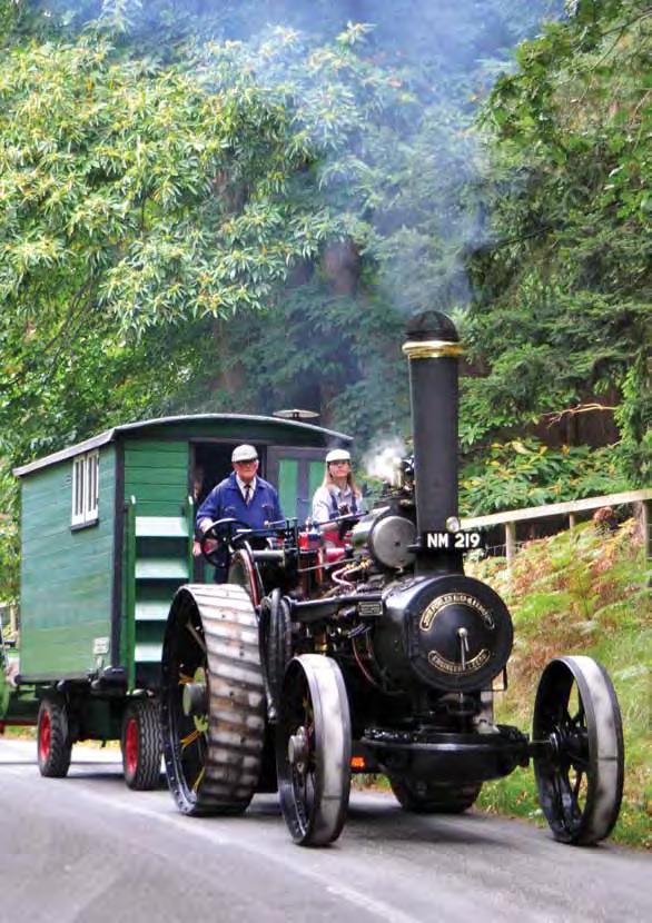
21/2 inch scale Mamod Roller!
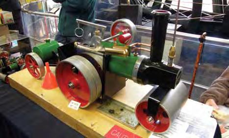
Mamod line shaft diorama.
Steam Toy show dates for 2015/2016:
Date Location
16th/17th May 2015Kempton Great Engines, Kempton Park, Middlesex
23rd May 2015Rainbow Children’s Hospice, Wellington Inn, Eastwood, Nottinghamshire
13th June 2015Black Country Living Museum, Dudley, West Midlands
4th/5th July 2015Kings Park, Boscombe, Bournemouth
5th July 2015 Twyford Water Works, Winchester, Hampshire
5th September 2015Owston Ferry Pumping Station, Lincolnshire
20th September 2015Armley Mills Industrial Museum, Leeds
10th October 2015Winterbourne House and Gardens, Birmingham
10th January 2016Magical Meccano, Abbey Pumping Station, Leicester
7th February 2016Steam Toys in Action, Abbey Pumping Station, Leicester
Launching this year’s model competition:
Flatbed trailer in World War 1 livery
Part One
The drawings and instructions for building the trailer are in this magazine, the detail for painting will be in the next. Of course you are free to build and decorate as you like, but get it done and bring it to Dorset!
You can use your own measurements, but if you follow these use either the imperial or metric, not both, as they might not agree.
Materials
Mountboard:
Try your local framing shop for scraps.
Card:
Supermarket boxes are strong, pet food boxes tend to be thin and strong, but glossy surfaces may not glue as easily.
MDF:
Thin MDF is great for this but DO NOT inhale dust when cutting!
Wheels:
Try wheels from Hobby’s catalogue (www.hobby.uk.com) or look on ebay
Towbar / A-frame
Try a wire coat hanger, or something a bit thicker.
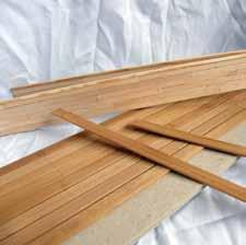
Planking:
Coffee stirrers, lolly sticks, old wooden table mats or thin card (cereal packet) cut into strips will look realistic when painted.
Glue:
I used wood glue.
Instructions
Base:
You need to begin by creating a sturdy base, one that won’t flex or wear over time and stress when being pulled by your Mamod or Wilesco. I suggest putting three layers of mountboard together, 11ins x 4.5ins (28cm x 11cm). Leave the glued board under a weight to dry or it will warp! You could also use thicker card, MDF, wood, whatever you have available. When it’s dry add a central board to reinforce it, 11ins x 2.75ins (28cm x 7cm). Glue these together and on to the underside of the base. Again leave to dry thoroughly under a weight.
Front and Back Boards:
Use two pieces of mountboard 4.75ins x 1.5ins (11.8cm x 4cm) for each end, glue together, weight and leave to dry. For the side boards repeat the above with pieces 11ins x 1.5ins (28cm x 4cm).
I then covered the outsides of all four boards with trimmed coffee stirrers to look like they are built of planks. To finish the job really neatly glue stirrers across the tops of all four pieces. You could also plank the base, you will need wider pieces of wood for this to look real, lolly sticks would do well.
Decide whether you want to fix the sides on the trailer or hinge them. If you want hinges, these are easily made from two strips of thin material glued along the length of both sides (see photo). You will need to devise a method of securing
them in place. Glue the head and tails boards on in line with the sides.
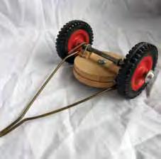
Wheel and axle assembly:
I have included two sets of instructions, easy, and more adventurous!
Simple method:
Cut two strong circles about 2.5ins (6cm) diameter (or four of mountboard and glue in pairs). These will form a simple turntable for your front wheels. Put a small nut and bolt or other fixing through the centre to allow them to turn. It is a good idea to put a piece of tracing paper, greaseproof, or even a bit of Vaseline between to ensure it turns easily. Attach two small blocks to the underside and fix your wheels and axle to them. Mount this at the front of your trailer on blocks to give your wheels enough clearance.
Advanced method:
Have a careful look at the pictures! Create two frames, these will carry your
turntable rings. Make two rings from board, card wood or metal, about 2.5ins (6cm) diameter, 0.25ins (6mm) thick. Assemble your structure by gluing the rings onto your frames and then bolting the frames together. You then need to create leaf springs from card, wood or metal and attach these to your frame. They don’t need to work! Gluing layers of card around a former works well.
Remember to check that your wheels will be able to turn over the edge of the upper frame. Add a towing bar to the front of the lower section of your undercarriage assembly.
For the rear wheels the most important thing is to make your trailer level. You need to carefully work out the position of your wheels/axle and then add leaf springs and blocks to make the trailer level.
Hopefully you now have a trailer! Ideas for painting, embellishments etc. will be in Part Two in the next issue.
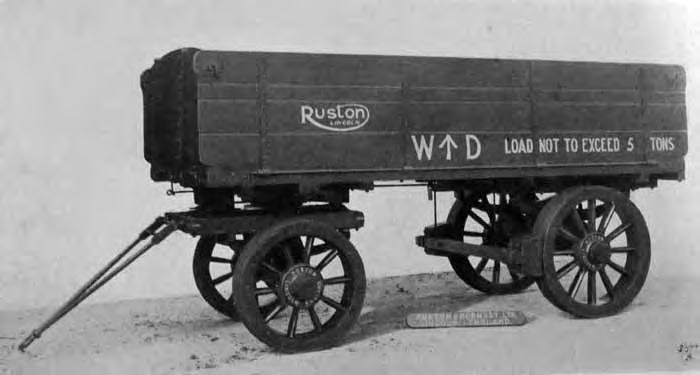
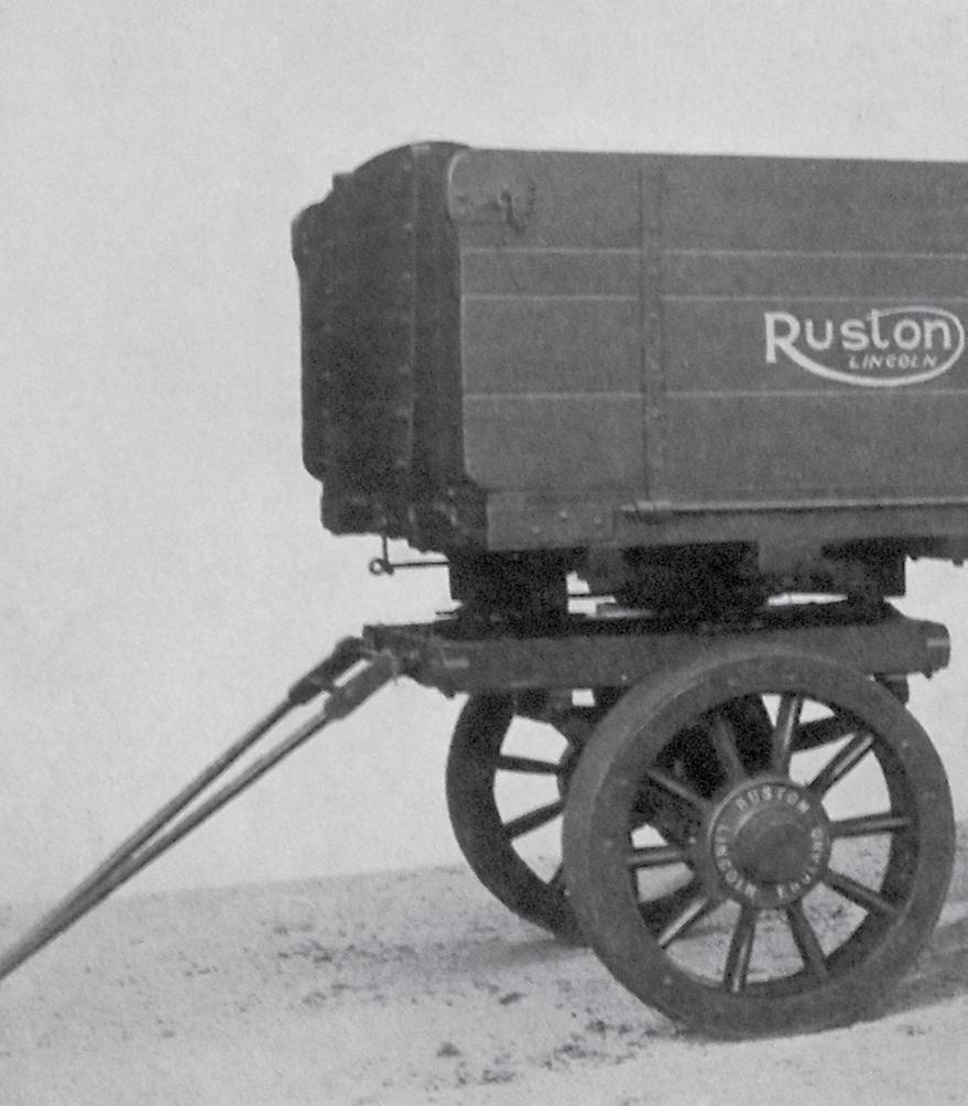
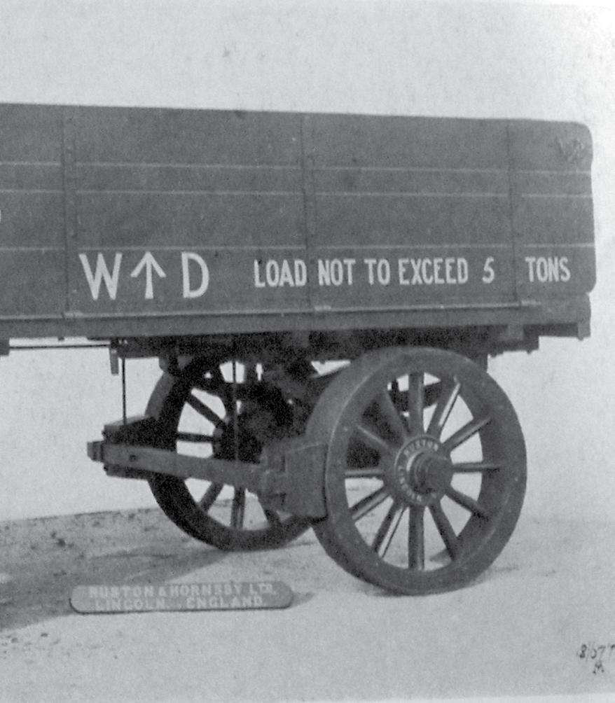
An original War Department trailer. Photograph reproduced with kind permission from Colin Tyson, ‘Old Glory’.
Advanced Front Turntable
Turntable assembly:
Upper layer showing cut back corners to allow wheels to pass and position of turntable ring.
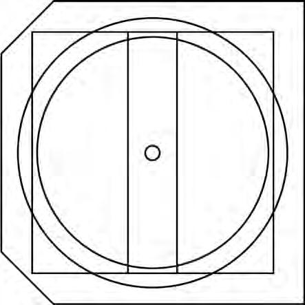
Glue together upper frame/turntable/greaseproof and lower set.
Make sure bolt is not too long to prevent fixing axle across leaf springs.
Nut and bolt ---------------------k
Upper frame ---------------------k
Upper turntable ------------------k
Layers of greaseproof -------------k
Lower turntable ------------------ k
Lower frame ---------------------k
Leaf spring ----------------------k
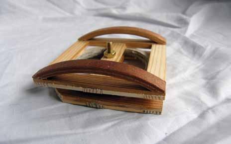
Trailer base (partly planked) and sides. Simple undercarriage assembly.
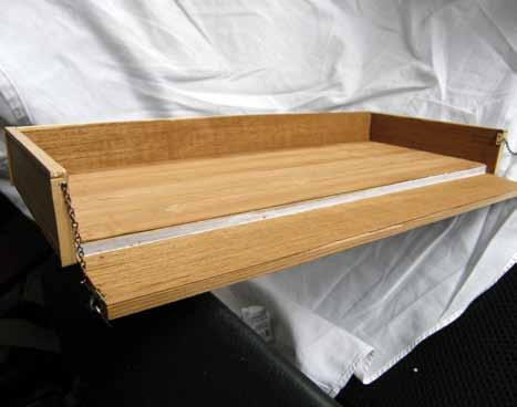
Trailer assembled showing fabric hinge.
Advanced alternative front turntable construction.
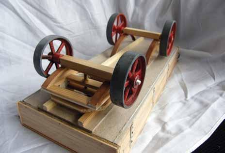
Underneath of trailer ready for gluing.
Kate’s Progress
by Kevin Munn
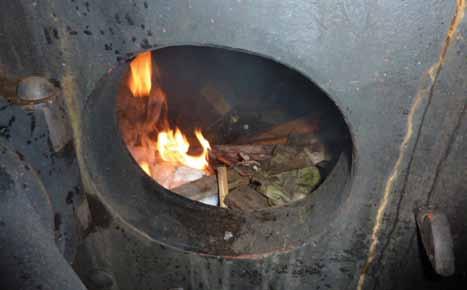
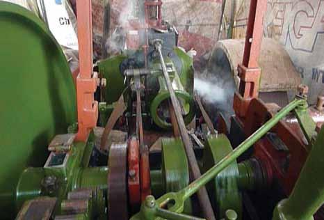
I finally got all the bits and pieces back on that would allow me to steam the engine up. I was, of course, both nervous and excited that it would be in steam again after nearly six years of work. I decided to just use wood to heat it up, as it can quickly be put out if any problems were to occur. In a previous article you might recall I had heated the boiler up so as to de-stress the plate work of the firebox, which it did. It also acted as a check for the boiler for leaks, albeit not under pressure. Of course, when it is under pressure, leaks and other problems can occur, which they did!
I also decided to only take it to 50psi on its first steam up, so it wasn’t a total shock to the system after all this time. So, after doing all the checks you should do before light up, I put some rags onto a shovel and soaked it with diesel. NEVER use petrol or any other highly flammable liquid to start the fire, as it flares up so quickly you would never get away from the flames in time and could get seriously burnt. The match was struck and the rags lit and put into the firebox. Once the rags where burning well, small pieces of timber were put on, followed by larger pieces, until I got a roaring fire
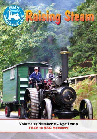
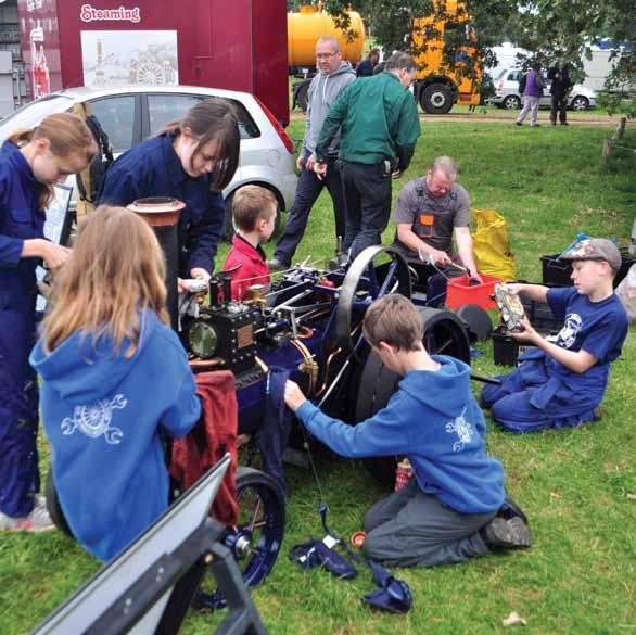
Cover: Steam Apprentices polishing ‘Lady Sylvia’ at the NTET Road Run.
First fire in 6 years!
Checking the tube plate in the firebox.
Finally in motion!
going. It was then a matter of time and patience whilst the water in the boiler warmed up to over 100oC. The needle started to move very slowly, it seemed like watching paint dry!! Whilst that was happening I did all the other checks you should do, like oiling up and tightening up the mud holes gaskets as the heat ‘softens’ them and, with the pressure pushing on them, in effect the spigot gets ‘pushed’ outwards and the nut holding it all in place becomes loose. I of course checked for leaks, not only from where there are gaskets etc between the boiler and parts I had put on, but also around the horn plates and firebox which had been banged and moved around during the assembly of the new firebox. Finally it reached 50psi so I opened the regulator, the engine turned, hoorah!! See the first turn over on YouTube: https://www.youtube.com/watch?v=EIYE 6ebjYq8&feature=youtu.be
As you can see I do have steam coming from the piston valve rod and on the right from the cylinder drain valves. I wasn’t worried about the steam coming from the cylinder valves, but of course it is best not to have steam coming from around packings. I made a note of where the leaks were coming from and then tried the injector to see if it would still work. As the pressure wasn’t very high, I knew it wouldn’t work as efficiently as it does at higher pressures, but equally I knew it should work as I have operated at 50psi when closing down, at the end of the day for example. It worked and I could hear the water going along the pipe. By touching the feed pipe after it had worked for a moment or so, I could tell that the feed pipe was getting cooler, so therefore water was going into the boiler. I then operated the pump and this is when I experienced problems, more of which in my next article.
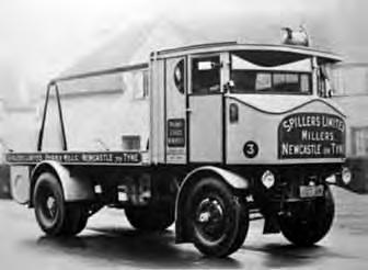
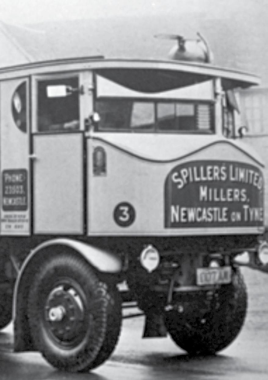
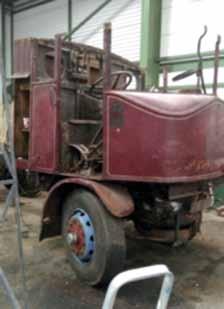
Sentinel steam wagon DG 8647
by David Lee
Last year you may remember an article in Raising Steam regarding a Sentinel DG that was repatriated from Canada. Well, since then a lot has happened. After a jet wash before restoration was started we found lettering and sign writing coming through the top layers of paint. One was Bitumous Tar Products, which we knew about, and one that, according to the sentinel records, shouldn’t be there, W. & J. Glossop’s Halifax Depot. So with this information and after a recent trip to the same yard in Canada from where we got the sentinel, the ex-owner found the
original number plate. I sent pictures of this to Tony Thomas, the curator at the Sentinel Driver’s Club and he confirmed
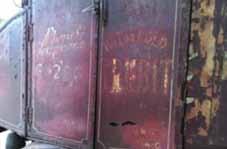
that the original information gathered by Alan Dukes in 1988 is incorrect and the wagon that we got is actually DG 8647. The history of our Sentinel is pretty much the same but also includes W. & J. Glossop:
• Built on 27th January 1932 and delivered to Spillers Flour Mills in Grimsby
• After WW2 sold to Bitumous Road Products, Middlesbrough
• Then sold to W. & J. Glossop, Hipperholme, Halifax Depot and was named Sally
• F. C. Lamb of Bromsgrove
• Matthews brothers, Ontario, Canada in 1958
• Dave Lee from Tamworth in 2013
Restoration of DG 8647
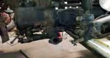
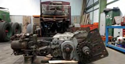
I am happy to announce that restoration has now started on Sentinel DG 8647. The first job that we did was to take the engine out, which meant disconnecting a number of things i.e. cylinder drain cables and steam feed pipe.
Once everything was disconnected from the engine, we had to take off the bolts on the mounting plate which
were holding the engine in place on the chassis, there were seven bolts on each plate. As you can see from the photos on the next page, the bottom row of bolts were redrilled at some point in its life, which suggests to me that it had a engine change at some point and the holes of the old engine didn’t line up to the new one.
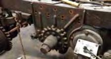
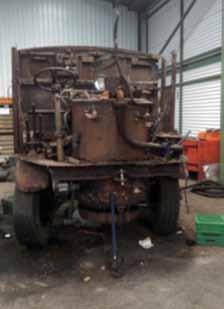
The next job that we did was to take the boiler out to assess how bad it was. The first thing we had to do was to take the roof off which turned out to be quite easy as it was only held on by T-brackets on each of the pillars, so once these were removed the roof just lifted off.
Now we had to take the front off and that was only held on by a row of bolts that went through the floor. We did have to take off the pressure gauge before we lifted it off and when we did it showed the whole of the cab and boiler.
As you can see in the last photos, before we can remove the boiler we need to take all the pipe work off as well as the ash pan and fire bars. The boiler is bolted to the chassis rails on four feet and each foot has two bolts in. The bolts are what’s called ‘fitted bolts’ where the shank of the bolt is the same size as the hole, so the bolt has to be fitted into the hole with a hammer. It is the tight fit that stops the boiler moving around and cracking pipes and fittings.
The Water Gauge
by Julian Tyrrell
Why do we need a water gauge on a traction engine?
Basically it allows you to see the water level in the boiler. If you look at your kettle in the kitchen, this usually has a clear plastic window so that you can see if you have enough water for your cup of tea. For the same reason the water level in the boiler is important, we need the right level of water to make the engine work.
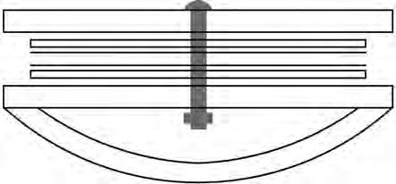
Take a look at the cross section drawing below of a typical boiler found on most traction engines (you’ll have to ask a Sentinel lorry owner what a vertical boiler looks like inside). The firebox is completely surrounded by a water jacket and near the top the tubes run though the barrel of the boiler to the
smoke box. We have to keep the water level above the top of the firebox and the tubes, while leaving enough space for the steam.
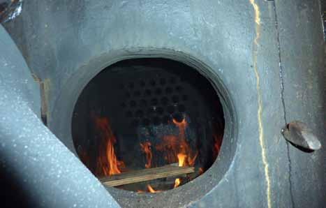
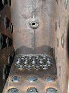
The photo of my DCC boiler (Figure 2) shows the inside of the firebox looking at the front and top. You can see the 18 tubes that go through the barrel from the front of the box. In the centre of the top you can see a bush welded in place, which is where the ‘fusible plug”’is screwed in. This is a safety device that prevents damage to the boiler if the water level gets too low.
Figure 3 shows a typical fusible plug in more detail. It is a brass bolt that has been drilled though the centre, and then a screw thread cut using a tap and the hole then filled with lead; you can see the grey lead in the centre of the brass
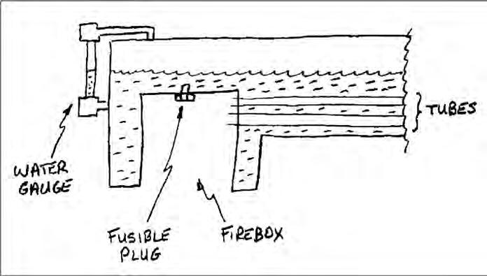
Figure 1. Cross-section of boiler, showing water level.
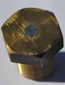
bolt. The reason for the screw thread is to stop the lead just falling out when you pick it up; it gives it something to grip onto inside the hole.
The melting point of lead is 327.5°C, so that with water covering the plug the lead remains solid. But, for those of you that have done this in Physics, the boiling point of water depends on pressure; the higher the pressure the higher the boiling point. Your kettle boils at 100°C, just right for a cup to tea, but in a traction engine at 200psi water boils at about 195°C. This is still less than the melting point of lead, so it remains solid and keeps the hot water and steam in the boiler.
What happens if the water level drops and the top of the firebox is not covered? Well, the heat of the fire raises the temperature of the top of the firebox and the lead melts, this leaves the hole in the plug to let all of the steam out.
This blast of steam blows the fire out and reduces the pressure in the boiler to zero. When this happens it is really spectacular, with a great cloud of steam, ash and coal being blown out of the damper!
So you see keeping the water the correct level in the boiler is really important. The water gauge glass is positioned on the boiler so that the level on the glass is at the correct height –enough to cover the firebox and tubes and not too much so that the engine ‘primes’ and fills the piston with water.
Figure 4 shows the water gauge demonstrator with water – the red line helps the level to be seen easier (some engines use black & white stripes). The cocks fitted to the top and bottom of the gauge allow the ‘blowing down’ to clear and check that it works correctly, as well as isolating the gauge if the glass breaks.
Figure 2. Inside the firebox, showing tubes and where the fusible plug goes.
Figure 3. A fusible plug.
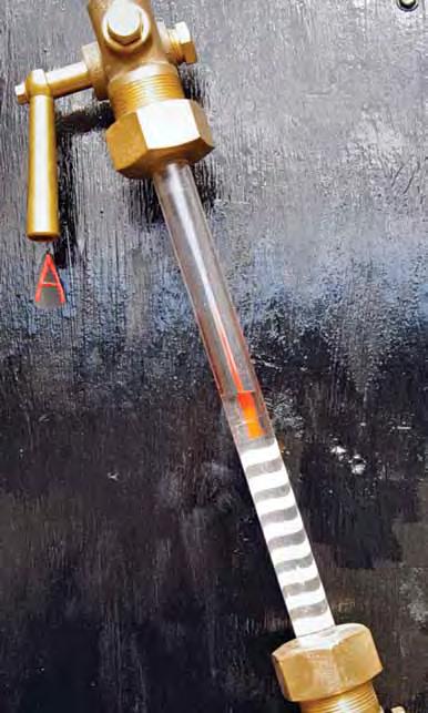
Figure 4. Water gauge showing the level on the red line.