

Product: WHEEL LOADER
Model: 994K WHEEL LOADER MM9
Configuration: 994K Wheel Loader MM900001-UP (MACHINE) POWERED BY 3516E Engine
Disassembly and Assembly
994K Wheel Loader Engine Supplement Media
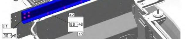
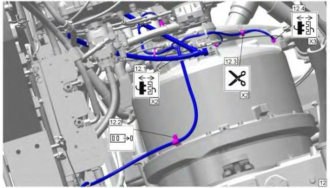
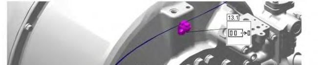
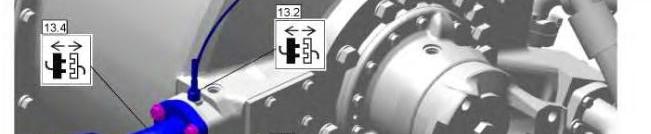
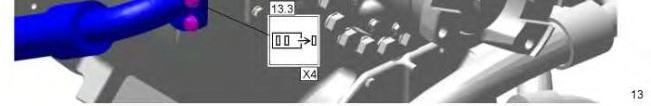
Engine - Remove and Install - Engine and Torque Converter
SMCS - 1000-010; 1002
Removal Procedure Table 1
Required Tools
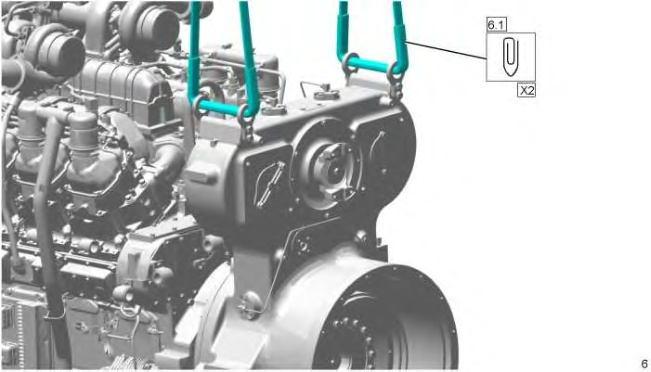
Tool Part Number Part Description Qty A 421-5663 Lifting Eye Assembly 2
Start By:
a. Remove the hood.
b. Remove the fan pump.
c. Remove the piston pump (steering).
d. Remove the piston pump (implement).
e. Remove the axle cooler pump.
f. Drain the engine oil.
Start By:
NOTICE
Care must be taken to ensure that fluids are contained during performance of inspection, maintenance, testing, adjusting, and repair of the product. Be prepared to collect the fluid with suitable containers before opening any compartment or disassembling any component containing fluids.
Refer to Special Publication, NENG2500, "Dealer Service Tool Catalog" for tools and supplies suitable to collect and contain fluids on Cat® products.
Dispose of all fluids according to local regulations and mandates.
Hot oil and components can cause personal injury.
Do not allow hot oil or components to contact skin.
NOTICE
Keep all parts clean from contaminants. Contaminants may cause rapid wear and shortened component life.
Note: Install caps and plugs on all openings to prevent dirt or debris from entering the system. Cleanliness is an important factor. Before the removal procedure, the exterior of the component should be thoroughly cleaned. This will help to prevent dirt from entering the internal components.
Note: For easier assembly, mark all hose assemblies, tube assemblies, wire harnesses, and cables for identification purposes.


This is the sample of the manual
Click on the download link for complete manual

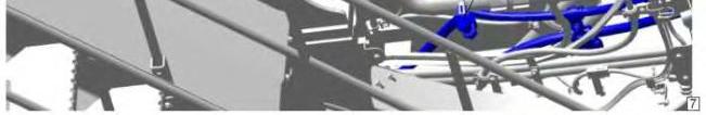

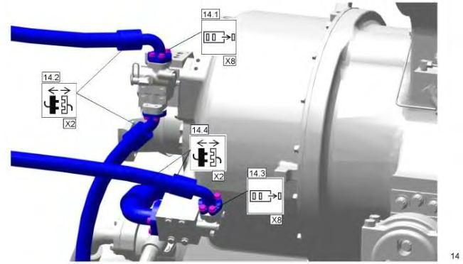


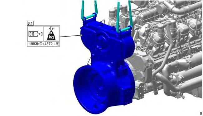
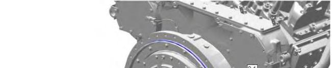
Installation Procedure
1. Install the engine in reverse order of removal.


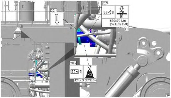
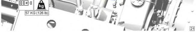
21 g06115024
Copyright 1993 - 2025 Caterpillar Inc. All Rights Reserved. Private Network For SIS Licensees. Mon Apr 14 10:38:48 UTC+0530 2025
Product: WHEEL LOADER
Model: 994K WHEEL LOADER MM9
Configuration: 994K Wheel Loader MM900001-UP (MACHINE) POWERED BY 3516E Engine
Disassembly and Assembly
994K Wheel Loader Engine Supplement Media Number -M0071300-09
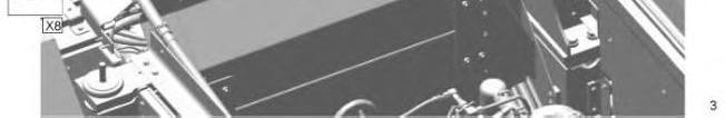
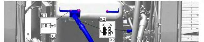
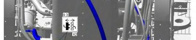
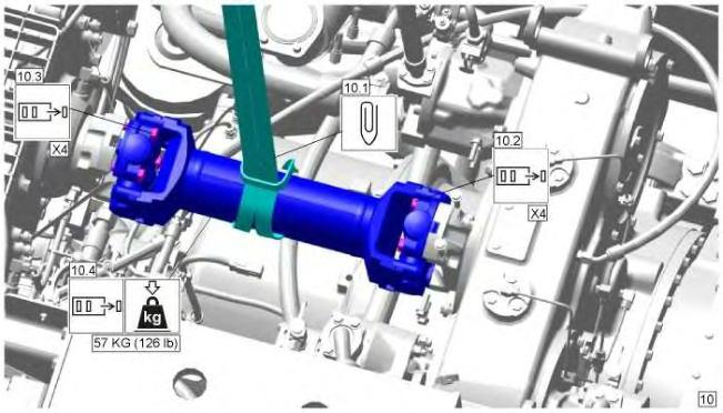
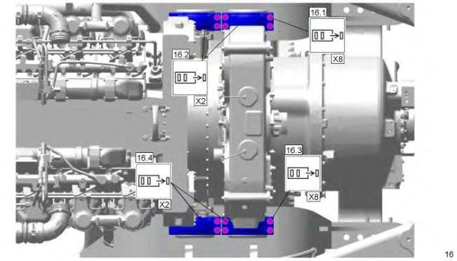
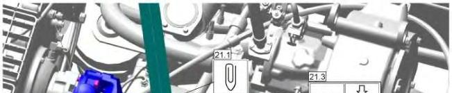
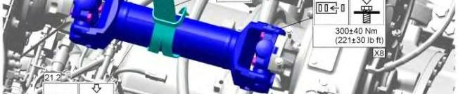
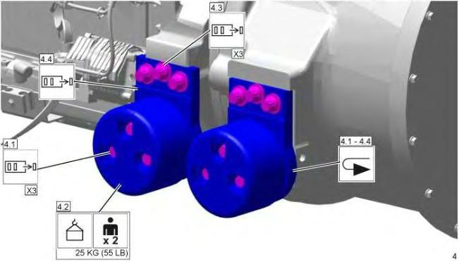
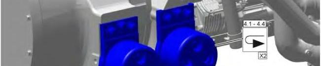
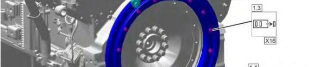
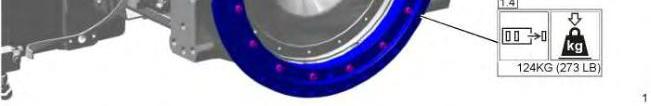
Pump Drive (Rear) from Engine - Separate
SMCS - 1000-076; 3108-076
Separation Procedure Table 1
Required Tools Tool Part Number Part Description Qty A 439-3940 Bracket As 2
Start By:
a. Remove the engine.
-11/11/2020
i06867602
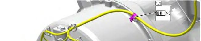


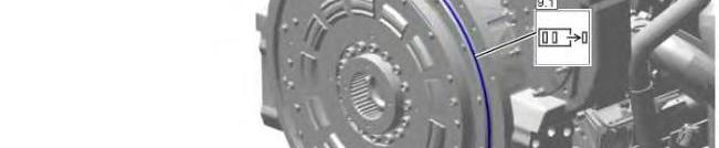
9 g06146945
Copyright 1993 - 2025 Caterpillar Inc. All Rights Reserved. Private Network For SIS Licensees. Mon Apr 14 10:38:01 UTC+0530 2025
Product: WHEEL LOADER
Model: 994K WHEEL LOADER MM9
Configuration: 994K Wheel Loader MM900001-UP (MACHINE) POWERED BY 3516E Engine
Disassembly and Assembly
994K Wheel Loader Engine Supplement
Media Number -M0071300-09
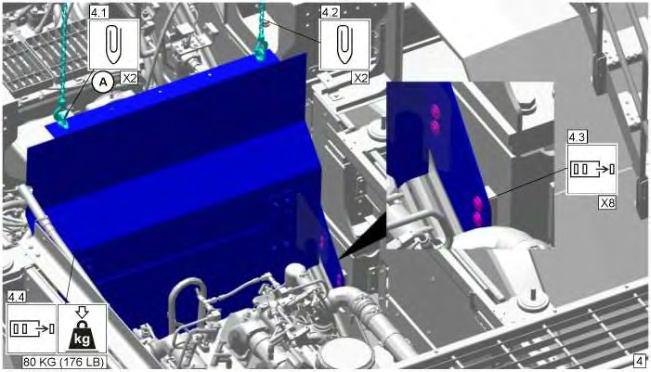
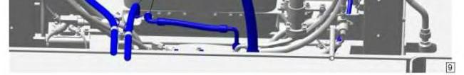
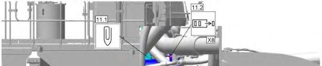
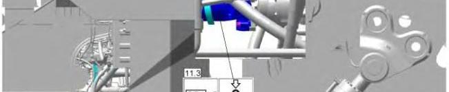
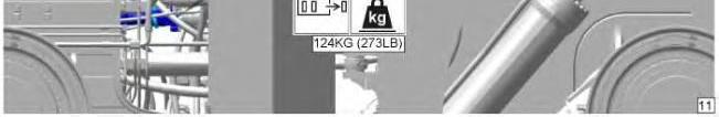
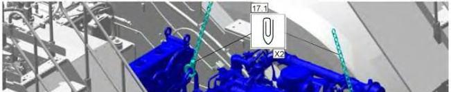
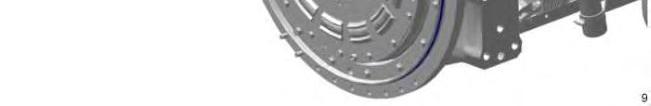
Torsional Coupling - Remove and Install
SMCS - 3252-010; 3252; 3279-010
Removal Procedure
Table 1
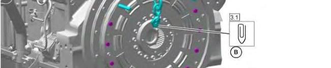
Required Tools Tool Part Number Part
A - 1/2 - 13 X 12 in. Guide Stud 2
B 439-3940 Bracket As 1
Start By:
a. Remove the rear pump drive.
-11/11/2020
i06867613

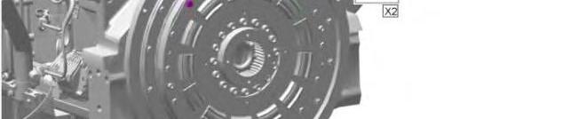
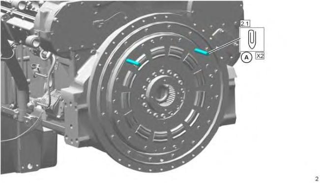

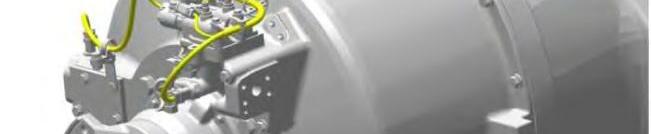
3 g06145664
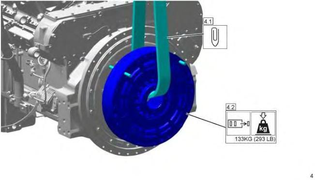
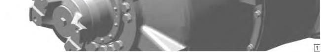
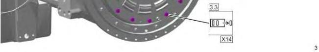
4 g06145666
Installation Procedure
1. Install the torsional coupling in the reverse order of removal. Mon Apr 14 10:37:27 UTC+0530 2025
Product: WHEEL LOADER
Model: 994K WHEEL LOADER MM9
Configuration: 994K Wheel Loader MM900001-UP (MACHINE) POWERED BY 3516E Engine
Disassembly and Assembly
994K Wheel Loader Engine Supplement
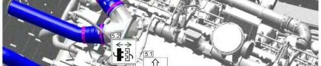
Flywheel Housing Adapter - Remove and Install
SMCS - 1157-010; 1157
Removal Procedure
Table 1 Required Tools
B - Loctite5127 Flange Sealant -
Start By:
a. Remove the torsional coupling.
This is the sample of the manual
Click on the download link for complete manual

Installation Procedure

End By:
Install the torsional coupling.