
This is the sample of the manual
Click on the download link for complete manual

Product: WHEEL LOADER
Model: 980K HLG WHEEL LOADER NEP
Configuration: 980K Wheel Loader High Lift Grapple NEP00001-UP (MACHINE) POWERED BY C13 Engine
Disassembly and Assembly
980K Wheel Loader C13 Engine Supplement
Media Number -KENR6443-02 Publication Date -01/08/2012 Date Updated -21/08/2012
i04403433
Engine, Torque Converter, Transmission and Output Transfer
Gears - Install
SMCS - 1006-012
Installation Procedure
Table 1 Required Tools
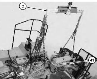
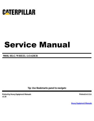
Illustration 1
g02586257
1. Use Tooling (C) and a suitable lifting device in order to lower the engine, torque converter, transmission and output transfer gears (41) into place. The weight of the engine and transmission is approximately 3389 kg (7472 lb).

Illustration 2
g02590258
2. With Tooling (C) and the suitable lifting device still supporting the engine and transmission install bolt (40). Tighten bolt (40 ) to a torque of 900 ±100 N·m (664 ± 74 lb ft). Repeat for the opposite side.
3
3. Use two people in order to install mount assembly (39). The weight of mount assembly (39) is approximately 25 kg (55 lb). Install bolts(37) and (38). Tighten bolt (38) to a torque of 900 ± 100 N·m (664 ± 74 lb ft). Repeat for the opposite side.
4
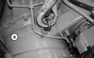
Illustration 5 g02586181
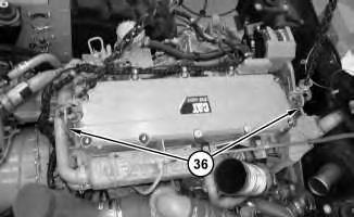
Illustration 6 g02586197
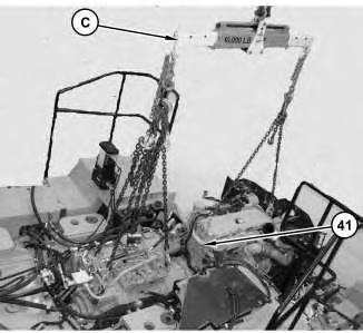
Illustration 7 g02586257
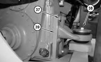
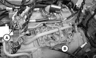
4. Remove Tooling (C). Disconnect the suitable lifting device from lift points (36). Disconnect the suitable lifting device from Tooling (B) and Tooling (A). Remove Tooling (B) and Tooling (A) .
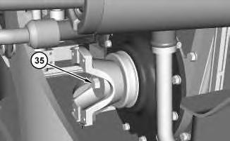
Illustration 8
g02590380
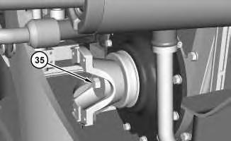
5. Install the yoke and bolt (35). Install bolt (35) to the following torque 475 ± 60 N·m (350 ±44 lb ft).

Illustration 9
g02585578

Illustration 10
g02585403
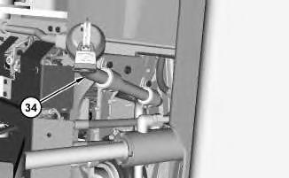
6. Install transmission oil fill tube assembly (34). Connect transmission oil fill tube assembly (34) .
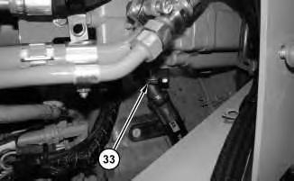
Illustration 11
7. Connect hose assembly (33) to the steering pump.
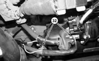
Illustration 12
8. Connect cable assemblies (32) to the electronic starter motor.
13
14

Illustration 15 g02584116
11. Connect clamp (28) .
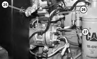
Illustration 16
12. Connect tube assemblies (27) .
13. Connect harness assembly (26) .
14. Connect ground strap (25) .

Illustration 17
15. Connect harness assembly (23) .
16. Connect hose assemblies(22) and (24) .
g02583197
18
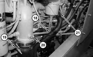
17. Connect hose (18). Connect clamps(21). Connect hose assembly (20). Connect clamps (19) .
19
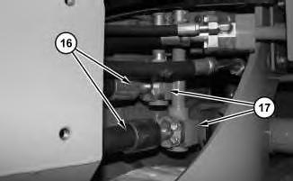
Illustration 20
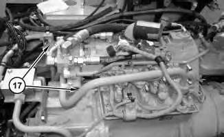
18. Install tube assemblies (17). Connect tube assemblies (17) to hose assemblies (16) .

Illustration 21
g02580959
19. Use a suitable lifting device in order to install secondary steering pump (9). The weight of secondary steering pump (9) is approximately 38 kg (84 lb). Install nuts(15) .
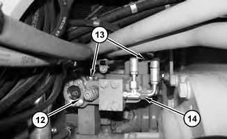
Illustration 22
g02580898
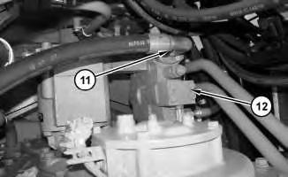
20. Install secondary steering valve (12) and bolts (13). Connect hose assemblies (14) .

21. Connect hose assembly (11) to secondary steering valve (11) .
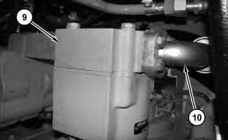
22. Connect hose assembly (10) to secondary steering pump (9) .
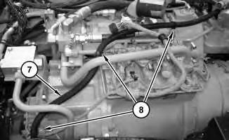
Illustration 25
23. Reposition hose assembly (7) and install clamps (8) .

26
24. Connect hose assembly (7) to the fuel tank.
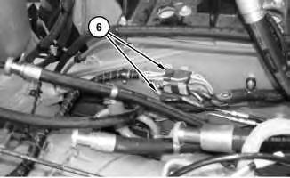
Illustration 27
25. Reposition harness assemblies(6) and connect harness assemblies (6) .
28
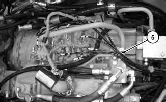
26. Connect all ten hose assemblies (5) and the cable strap assemblies.

29
27. Reposition hoses (4) through the sound barrier (3).
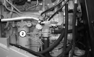
Illustration 30
28. Connect hoses (2) .

31
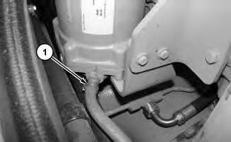
29. Connect hose (1) to the transmission oil cooler.
30. Fill the power train oil. Refer to Operation and Maintenance Manual, "Power Train Oil - Change" for the correct filling procedures.
End By:
a. Install the steering valve.
b. Install the center drive shaft.
c. Install the rear drive shaft.
d. Install the power train guard.
e. Install the crankcase guard.
f. Install the clean emissions module.
g. Install the hydraulic tank.
Product: WHEEL LOADER
Model: 980K HLG WHEEL LOADER NEP
Configuration: 980K Wheel Loader High Lift Grapple NEP00001-UP (MACHINE) POWERED BY C13 Engine
Disassembly and Assembly
980K Wheel Loader C13 Engine Supplement Media Number -KENR6443-02
i04397916
Engine, Torque Converter, Transmission and Output Transfer
Gears - Remove
SMCS - 1006-011
Removal Procedure
Table 1
Required Tools
Start By:
A. Remove the hydraulic tank.
B. Remove the clean emissions module.
C. Remove the crankcase guard.
D. Remove the power train guard.
E. Remove the rear drive shaft.
F. Remove the center drive shaft.
G. Remove the steering valve.
1. Drain the power train oil. Refer to Operation and Maintenance Manual, "Power Train Oil - Change" for the correct draining and filling procedures.
2. Turn the battery disconnect switch into the OFF position.
1
3. Disconnect hose (1) from the transmission oil cooler.

Illustration 2
4. Disconnect hoses (2) .
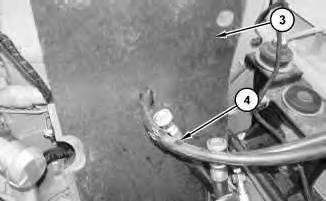
Illustration 3
5. Pull hoses (4) through sound barrier (3). Remove sound barrier (3) .
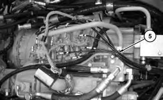
Illustration 4
6. Disconnect all ten hose assemblies (5) and the cable strap assemblies from the transmission.
Illustration 5
g02580576
7. Disconnect harnessassemblies(6) and reposition out of the way.
Illustration 6
g02580638
8. Disconnect hose assembly (7) from the fuel tank.
Illustration 7
g02580657
9. Disconnect clamps (8) and reposition hose assembly (7) .

8
10. Disconnect hose assembly (10) from secondary steering pump (9) .
9
11. Disconnect hose assembly (11) from secondary steering valve (12) .
Illustration 10
g02580898
12. Disconnect hose assemblies(14) from secondary steering valve (12). Remove bolts (13) and secondary steering valve (12) .
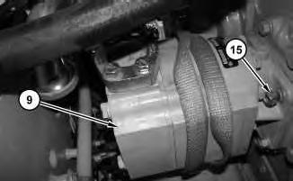
Illustration 11
g02580959
13. Attach a suitable lifting device to secondary steering pump (9). The weight of secondary steering pump (9) is approximately 38 kg (84 lb). Remove nuts (15) and secondary steering pump (9) .
12

13
14. Disconnect hose assemblies(16) from tube assemblies(17). Remove tube assemblies (17) .

14
15. Disconnect clamps (19). Disconnect hose assembly (20). Disconnect clamps (21) and hose (18) .
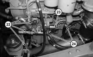
Illustration 15
16. Disconnect hose assemblies(22) and (24). Disconnect harness assembly (23) .
Illustration 16
17. Disconnect ground strap (25).
18. Disconnect harnessassembly (26) .
19. Disconnect tube assemblies (27) .
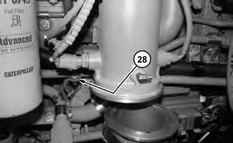
Illustration 17 g02584116
20. Disconnect clamp (28) .

18
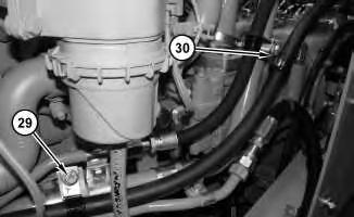
21. Remove clips (29) and (30) .

19
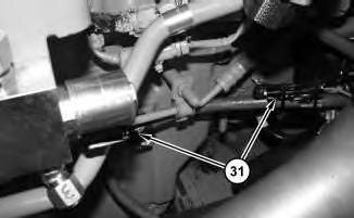
22. Disconnect harnessassemblies(31) .
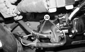
Illustration 20 g02585336
23. Disconnect cable assemblies (32) from the electronic starter motor.
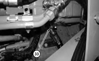
Illustration 21
g02585397
24. Disconnect hose assembly (33) from the steering pump.
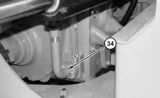
Illustration 22
g02585403
This is the sample of the manual
Click on the download link for complete manual
23
25. Disconnect transmission oil fill tube assembly (34). Remove transmission oil fill tube assembly (34)
24
26. Remove bolt (35) and the yoke.