
980G WHEEL LOADER

Product: WHEEL LOADER
Model: 980G WHEEL LOADER 2SR
Configuration: 980G WHEEL LOADER 2SR00651-UP (MACHINE) POWERED BY 3406 ENGINE
Disassembly and Assembly
980G Wheel Loader Engine Supplement
-SENR5873-03
Aftercooler - Install
SMCS - 1063-012
Installation Procedure
Table 1 Required Tools
A 138-7573 Link Bracket 2
Keep all parts clean from contaminants. Contaminants may cause rapid wear and shortened component life.
1. Clean all parts and inspect all parts. If any parts are worn or damaged, use new Caterpillar parts for replacement.
i01035136

1
2. Install O-ring seal (26) to core assembly (25). Repeat the procedure for the other end of the core assembly.
Note: Lubricate the O-ring seals with a suitable lubricant.
2
3. Install the gasket and core assembly (25) to aftercooler housing (24) .
Illustration
g00533722
Illustration
g00533720
3
4. Install the gasket and cover (22) to aftercooler housing (24) .
Illustration 4
5. Install 22 bolts (22) in order to secure cover (23) to aftercooler housing (24) .
Illustration
g00533719
g00533718
Illustration 5
g00533717
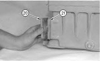
6. Install the gasket and adapter (20) and (21) to the aftercooler. Repeat the procedure for the other end of the aftercooler.

Illustration 6
7. Install six gaskets (19) to the engine.
g00533696
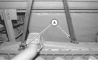
Illustration 7
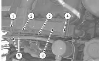
Typical Example
8. Attach Tooling (A), as shown.
g00518006
9. Install the aftercooler with a hoist and suitable lifting slings. Weight of the aftercooler is 34 kg (75 lb).
This is the sample of the manual
Click on the download link for complete manual
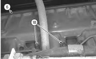
Illustration 8
Typical Example
This is a view under the machine.
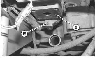
Illustration 9
Typical Example
This is a view of the front of the aftercooler.
10. Install 12 bolts (18) in order to secure aftercooler (6) to the engine.
11. Remove the hoist and the suitable lifting sling.
g00533677
g00533676
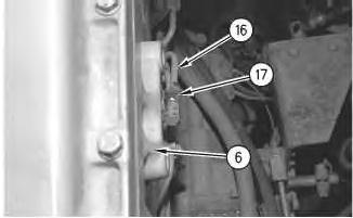
Illustration 10
Typical Example
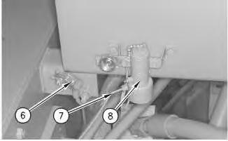
12. Connect tube (16) to aftercooler (6) and tighten retaining nut (17) .
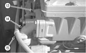
Illustration 11
g00533661
13. Position the gasket and elbow (14) to aftercooler (6). Install four bolts (13) in order to secure elbow (14) to aftercooler (6) .
14. Install the bolt and clip (15) to elbow (14) .
g00533670
12
15. Position the gasket and elbow (12) to the aftercooler (6). Install four bolts (11) in order to secure elbow (12) to aftercooler (6) .
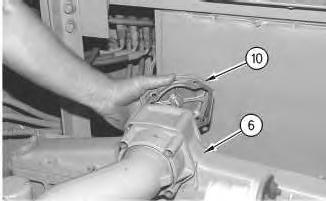
Illustration 13
Typical Example
g00533597
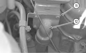
16. Install the gasket and plate (10) to aftercooler (6) .
Illustration
g00533628
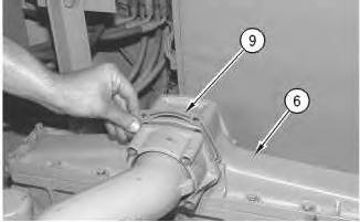
Illustration 14
Typical Example
17. Position gasket (9) to aftercooler (6) .
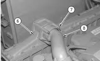
Illustration 15
g00533552
18. Install four bolts and nuts (7) in order to secure tube assembly (8) to aftercooler (6) .
g00533559
16
19. Position the fuel filters on the aftercooler and install two bolts (5) .
20. Position the air conditioner hose in place and install the bolt to secure clip (1) .
21. Position the ether aid engine line (3) in place. Secure the clip with bolt (4) .
22. Connect the ether aid engine line (3) and tighten retaining nut (2) .
23. Fill the cooling system. Refer to Operations and Maintenance Manual, "Cooling System Coolant - Change" for the machine that is being serviced.
End By:
a. Install the side panel on the right side of the machine. Refer to Disassembly and Assembly, "Side Panels - Remove and Install" for the machine that is being serviced.
b. Disconnect the steering frame lock. Refer to Disassembly and Assembly, "Steering Frame Lock - Separate and Connect" for the machine that is being serviced. Copyright 1993 - 2023 Caterpillar Inc.
Product: WHEEL LOADER
Model: 980G WHEEL LOADER 2SR
Configuration: 980G WHEEL LOADER 2SR00651-UP (MACHINE) POWERED BY 3406 ENGINE
Disassembly and Assembly
980G Wheel Loader Engine Supplement
Aftercooler - Remove
SMCS - 1063-011
Removal Procedure
Table 1 Required Tools
A 138-7573 Link Bracket 2
Start By:
A. Connect the steering frame lock. Refer to Disassembly and Assembly, "Steering Frame LockSeparate and Connect" for the machine that is being serviced.
B. Remove the side panel on the right side of the machine. Refer to Disassembly and Assembly, "Side Panels - Remove and Install" for the machine that is being serviced.
NOTICE
Care must be taken to ensure that fluids are contained during performance of inspection, maintenance, testing, adjusting and repair of the machine. Be prepared to collect the fluid with suitable containers before opening any compartment or disassembling any component containing fluids.
Refer to Special Publication, NENG2500, "Caterpillar Tools and Shop Products Guide", for tools and supplies suitable to collect and contain fluids in Caterpillar machines.
i01034613
Dispose of all fluids according to local regulations and mandates.
At operating temperature, the engine coolant is hot and under pressure.
Steam can cause personal injury.
Check the coolant level only after the engine has been stopped and the fill cap is cool enough to touch with your bare hand.
Remove the fill cap slowly to relieve pressure.
Cooling system conditioner contains alkali. Avoid contact with the skin and eyes to prevent personal injury.
Note: Put identification marks on all lines, on all hoses, on all wires and on all tubes for installation purposes. Plug all lines, all hoses and all tubes. This will help to prevent fluid loss and this will help to keep contaminants from entering the system.
1. Drain the cooling system. The capacity of the cooling system is 81 L (21 US gal).
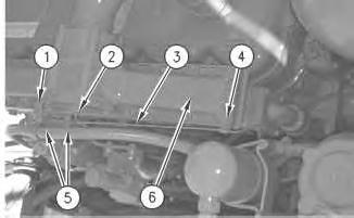
Illustration 1 g00533541
2. Loosen retaining nut (2) and disconnect ether aid engine line (3) .
3. Remove bolt (4). Position ether aid engine line (3) aside.
4. Remove the bolt from clip (1). Position the air conditioner hose aside.
5. Remove two bolts (5) that secure the fuel filters. Position the fuel filters aside.

Illustration 2
Typical Example
6. Remove four nuts (7) in order to separate tube assembly (8) from aftercooler (6) .
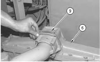
Illustration 3
Typical Example
7. Remove gasket (9) from aftercooler (6) .
g00533559
g00533552
Illustration 4
Typical Example
g00533597
8. Remove plate (10) and the gasket from aftercooler (6) .
Illustration 5
g00533628
9. Remove four bolts (11) and remove elbow (12) .
6
10. Remove the bolt and clip (15) from elbow (14) .
11. Remove four bolts (13) and remove elbow (14) .
Illustration 7
Typical Example
12. Loosen retaining nut (17) and disconnect tube (16) from aftercooler (6) .
Illustration
g00533661
g00533670
Illustration 8
Typical Example
13. Install Tooling (A) .
g00518006
14. Attach a hoist and suitable lifting slings to Tooling (A), as shown.
Illustration 9
Typical Example
This is a view of the front of the aftercooler.
g00533676
Illustration 10
Typical Example
This is a view under the machine.
15. Remove 12 bolts (18) from aftercooler (6). Remove the aftercooler from the engine. Weight of aftercooler is 34 kg (75 lb).
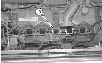
Illustration 11
Typical Example
16. Remove six gaskets (19) from the engine.
g00533696
g00533677

12
17. Remove adapter (20) and (21) and the O-ring seals from the aftercooler.
13
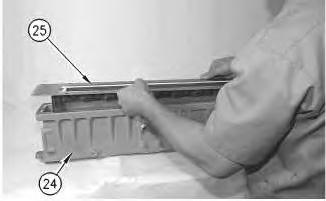
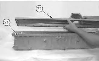
18. Remove 22 bolts (22) in order to separate cover (23) from housing (24) .

Illustration
g00533717
Illustration
g00533718
Illustration 14
g00533719
19. Remove cover (23) and the gasket from housing (24) .
Illustration 15
g00533720
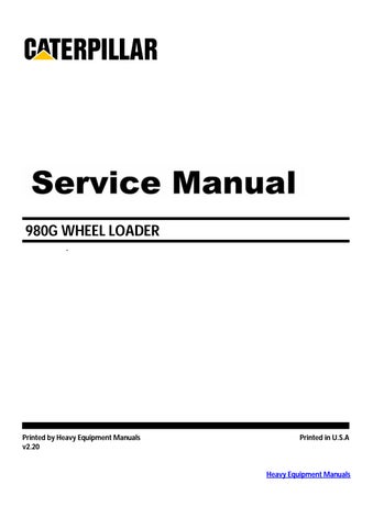
20. Remove core assembly (25) and the gasket from housing (24) .
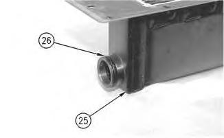
Illustration 16
g00533722
21. Remove O-ring seal (26) from core assembly (25). Repeat the procedure for the other end of the core assembly.
Copyright 1993 - 2023 Caterpillar Inc. All Rights Reserved. Private Network For SIS Licensees. Sun Aug 27 16:09:51 UTC+0530 2023
Product: WHEEL LOADER
Model: 980G WHEEL LOADER 2SR
Configuration: 980G WHEEL LOADER 2SR00651-UP (MACHINE) POWERED BY 3406 ENGINE
Disassembly and Assembly 980G Wheel Loader Engine Supplement
Air Cleaner - Remove and Install
SMCS - 1051-010; 1054-010
Removal Procedure
Start By:
A. Connect the steering frame lock. Refer to Disassembly and Assembly, "Steering Frame LockSeparate and Connect" for the machine that is being serviced.
1. Open the engine hood. The air cleaner is located on the left side of the machine.

1 g00514333
2. Loosen clamp (2) and hose clamp (3). Remove precleaner (1) .
i01003011
Illustration

2
3. Loosen hose clamps (4) at the air cleaner and at the turbocharger. Remove hose assembly (5) .
3
4. Disconnect electrical connector (6) .
5. Disconnect line (7) from the starting aid valve assembly (8) .
Illustration
g00514334
Illustration
g00514336

Illustration 4
g00514411
6. Disconnect air conditioning dryer (10) at the quick-connect fittings (9) .
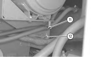
Illustration 5
7. Remove bolts (11) and (12) .
g00514321
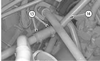
Illustration 6
g00514322
8. Loosen hose clamps (13). Remove the hose from dust ejector tube (14) .
Illustration 7
g00514323
9. Use a hoist and a suitable lifting sling to support the air cleaner assembly, as shown.
Illustration 8
g00514324
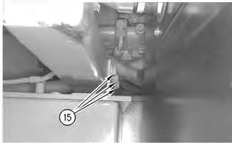
Illustration 9
10. Remove bolts (15) from both sides of the air cleaner support.
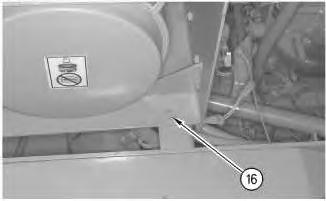
Illustration 10
11. Remove bolt (16) .
12. Remove the air cleaner assembly. Weight of the air cleaner assembly is 93 kg (205 lb).
Note: Use the following procedure to remove the air cleaner housing.
g00514325
g00514326
11
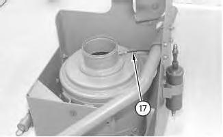
13. Disconnect line (17) .
12
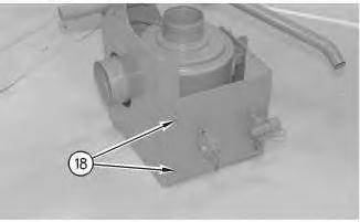
14. Remove bolts (18) .
Illustration
g00514327
Illustration
g00514329
This is the sample of the manual
Click on the download link for complete manual
Illustration 13 g00514330
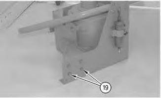
15. Remove bolts (19). Separate the two halves.
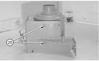
Illustration 14
16. Remove bolts (20) .
g00514331
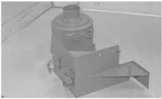
Illustration 15
17. Remove the air cleaner housing.
Installation Procedure
g00514332