

Product: TRACK LOADER
Model: 973 TRACK LOADER 32Z
Configuration: 973 TRACK LOADER / HIGH DRIVE / 32Z00001-UP (MACHINE) POWERED BY 3306 ENGINE
Disassembly and Assembly
DELCO REMY 20-SI SERIES ALTERNATOR
Media Number -SENR4978-00
Alternator
SMCS - 1405-015; 1405-016
Publication Date -01/08/1991
Date Updated -11/10/2001
Alternator
(1)
Disassemble Alternator
NOTE: The disassembly and assembly procedures are of the 3T6352 alternator. Other 20-SI alternators are similar.
Start by:
a. remove alternator.
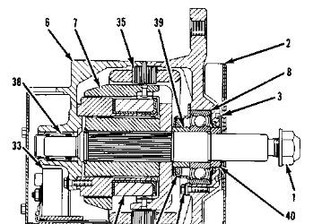
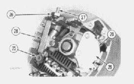
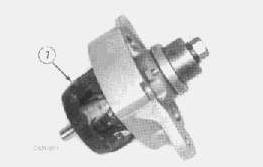
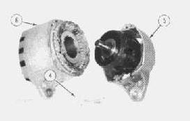
1. Remove pulley nut (1).
2. Remove pulley and fan (2).

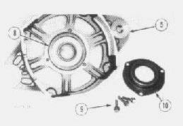
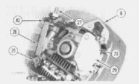
3. Remove shield (3). Remove four bolts (4) and separate drive frame (5) from rear frame (6).
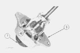
4. Attach puller as shown. Remove drive frame (5) from rotor (7). As drive frame (5) is separated from rotor (7), collars (40) and (39) are no longer secured. Remove collars (40) and (39).
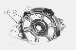
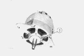
5. Remove three screws (9) and retainer (10). Use a puller to remove bearing (8) from drive frame (5).
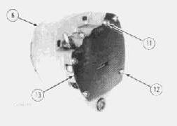
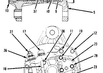
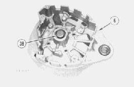
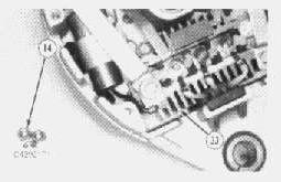
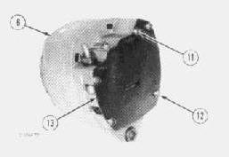
6. Remove screw (11) at the GND terminal. Remove four screws (12) and plate (13) from rear frame (6).
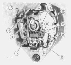
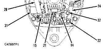
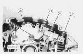
7. Remove three nuts (14) and disconnect the stator leads from rectifier (33).
8. Remove screw (15) at the battery terminal of rectifier (33).
9. Loosen nut (16). Remove R terminal (17) and strap (18) together.
10. Remove two screws (19) at the field oil terminals of regulator (20). Remove diode trio (21).
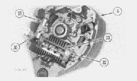
11. Remove screw (22) at the ground terminal of rectifier (33). Remove nut (23) at the ground terminal of regulator (20). Remove strap (24).
This is the sample of the manual
Click on the download link for complete Manual
12. Remove insulator (25) and loosen nut (26). Remove BAT terminal (27) and strap (28) together.
13. Remove screw (29) and regulator (20).
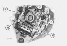
14. Remove screw (30) and capacitor (31).
15. Remove screw (32) and rectifier (33).
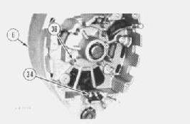
16. Loosen grommet (34) and remove stator (35) from rear frame (6).
17. Remove four screws (36) and remove field coil (37) from rear frame (6).
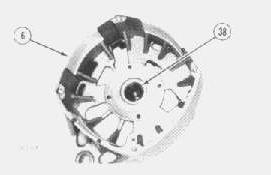
18. If necessary, remove bearing (38) from rear frame (6).
Assemble Alternator
NOTICE
Do not push on inner race of bearing (8) during installation. Damage to bearing (8) can occur. Push against the outer bearing race.
1. Install bearing (8) in drive frame (5). Install retainer (10) with three screws (9).
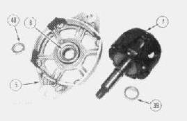
2. Place collar (39) on shaft of rotor (7). Insert the shaft of rotor (7) through bearing (8) in drive frame (5).
3. Place collar (40) on shaft of rotor (7).
4. Install spacers and nut as shown. Fully seat the shaft of rotor (7) in bearing (8).
5. If removed, install bearing (38) in rear frame (6). Use the 1P510 Drive Group.
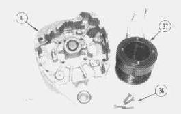
6. Place field coil (37) in rear frame (6). Install and tighten four screws (36).
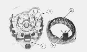
7. Place stator (35) in rear frame (6). Position grommet (34) in indentation (41).
8. Place rectifier (33) in rear frame (6). Install and tighten screw (32).
9. Place capacitor (31) in rear frame (6). Install and tighten screw (30).
10. Place regulator (20) in rear frame (6). Install and tighten screw (29).
11. Place BAT terminal (27) and strap (28) in rear frame (6). Make sure insulators (42) are properly positioned.
12. Install insulator (25) through the lead of capacitor (31) and strap (28).

13. Install and tighten screw (15). Tighten nut (26).
14. Place diode trio (21) on rectifier (33) and regulator (20).
15. Place R terminal (17) and strap (18) in rear frame (6). Make sure insulators (43) are properly positioned. Tighten nut (16).
NOTE: For correct operation, there is NO continuity between screw (15) and strap (28); or between nut (26) and rear frame (6); or between R term (17) and rear frame (6).
16. Make sure the insulators are installed on screws (19). Place the field coil leads on screws (19). Install and tighten two screws (19).
17. Place strap (24) on rectifier (33) and regulator (20). Install and tighten screw (22) and nut (23).
NOTE: For correct operation, there is NO continuity between screws (19) and the respective field coil lead.
18. Place the stator leads on the terminals of rectifier (33). Install and tighten three nuts (14) on the terminals of rectifier (33).
19. Position plate (13) on rear frame (6). Install and tighten four screws (12). Install screw (11) at the GND terminal.
20. Join rear frame (6) and drive frame (5). Install four bolts (4) and tighten to 6.2 ± 0.6 N·m (55 ± 5 lb in).
21. Install shield (3).
22. Install the pulley and fan.
23. Install the pulley nut and tighten to 100 ± 7 N·m (75 ± 5 lb ft). End by:
a. install alternator.
Copyright 1993 - 2023 Caterpillar Inc. All Rights Reserved. Private Network For SIS Licensees. Fri May 19 12:55:22 UTC+0530 2023

Product: TRACK LOADER
Model: 973 TRACK LOADER 32Z
Configuration: 973 TRACK LOADER / HIGH DRIVE / 32Z00001-UP (MACHINE) POWERED BY 3306 ENGINE
Disassembly and Assembly
Comfort Series Seat For Caterpillar Machines
Media Number -RENR2165-12
Publication Date -01/10/2013
Date Updated -31/10/2013
Air Suspension With Air Valve Knob Height AdjustmentAssemble
SMCS - 7324-016-AJ
Assembly Procedure
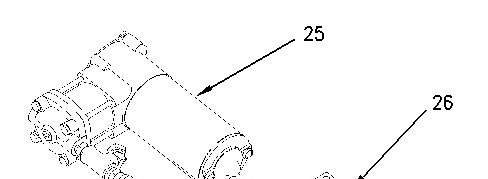
Illustration 1 g00891451
1. Install compressor assembly (25) to mount (26). Make sure that compressor assembly (25) is seated firmly in mount (26).
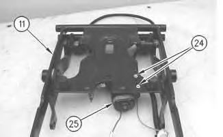
2
Install bolts (24) in order to attach compressor assembly (25) to scissor assembly (11).
3
Improper assembly of parts that are spring loaded can cause bodily injury.
To prevent possible injury, follow the established assembly procedure and wear protective equipment.
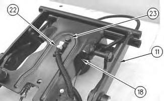
3. Install bolt (23) in order to attach spring assembly (18) to scissor assembly (11). Attach hose assembly (22) to spring assembly (18).
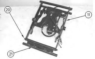
Illustration 4
4. Install shaft (20) in order to attach toggle assembly (21) to scissor assembly (11). Tighten the two nuts for shaft (20) to a torque of 15 ± 3 N·m (11 ± 2 lb ft).
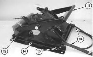
Illustration 5
g00872031
5. Install shaft assemblies (19) in order to attach tether straps (11A) and scissor assembly (11) to housing assembly (14). Tighten the nuts on shaft assemblies (19) to a torque of 20 ± 5 N·m (15 ± 4 lb ft). Install blocking in order to prevent scissor assembly (11) from falling.
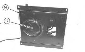
Illustration 6
g00872029
7
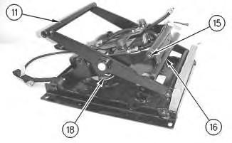
6. Install screw (17) in order to attach housing assembly (14) to spring assembly (18).
7. Install shaft (15) in order to attach toggle assembly (16) to scissor assembly (11). Tighten the two nuts for shaft (15) to a torque of 15 ± 3 N·m (11 ± 2 lb ft).
8 g00897454
9
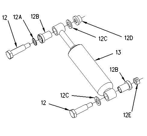
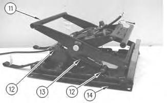
8. Install bearings (12B) to shock absorber (13).
9. Install bolts (12) in order to attach shock absorber (13) to scissor assembly (11) and housing assembly (14). Remove the blocking.
Note: Illustration 8 shows the location of lockwasher (12A), bearings (12B), washers (12C), nut (12D), and locknut (12E).
10. Repeat Steps 8 and 9 if the seat is equipped with a shock absorber on the opposite side.
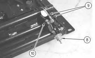
Illustration 10
g00871994
11. Connect harness assemblies (9) and hose assembly (10) to air valve (8).
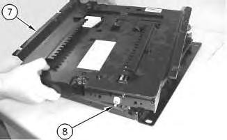
Illustration 11 g00871971
12. Position air valve (8) to upper housing assembly (7). Position upper housing assembly (7) to the seat.
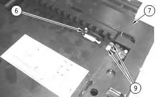
Illustration 12 g00871951
13. Install cable strap (6) in order to secure harness assemblies (9) to upper housing assembly (7).
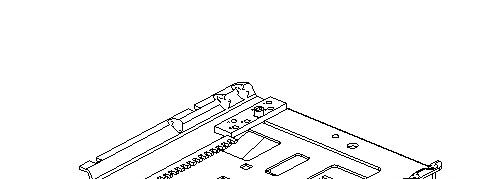
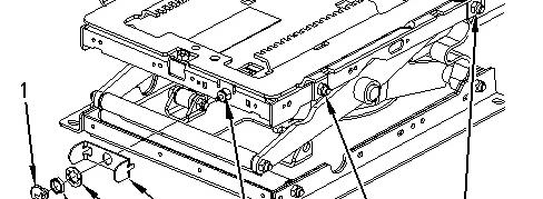
Illustration 13 g00876043
14. Install shaft assemblies (5). Tighten the nuts for shaft assemblies (5) to a torque of 20 ± 5 N·m (15 ± 4 lb ft).
15. Position plate (4) to the seat. Install lockwasher (3A) and nut (3) in order to secure air valve (8) to the seat. Tighten the setscrew in adjustment knob (1) in order to secure adjustment knob (1) to air valve (8).
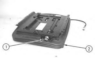
Illustration 14
16. Install boot (2) to the seat. Copyright 1993 - 2023 Caterpillar Inc. All Rights Reserved. Private Network For SIS Licensees.
g00871915
Fri May 19 11:55:53 UTC+0530 2023
Product: TRACK LOADER
Model: 973 TRACK LOADER 32Z
Configuration: 973 TRACK LOADER / HIGH DRIVE / 32Z00001-UP (MACHINE) POWERED BY 3306 ENGINE
Disassembly and Assembly
Comfort Series Seat For Caterpillar Machines
Media Number -RENR2165-12 Publication Date -01/10/2013 Date Updated -31/10/2013
Air Suspension with Air Valve Knob Height Adjustment -
Disassemble
SMCS - 7324-015-AJ
Disassembly Procedure
The air spring of the air suspension is filled with air pressure.
Prior to disassembly, release the air pressure in the air spring. Failure to do so could result in personal injury.
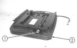
Illustration 1
1. Pull adjustment knob (1) in order to release the air from the seat.
2. Remove boot (2).
Illustration 2 g00876043
3. Loosen the setscrew in adjustment knob (1) and remove adjustment knob (1). Remove nut (3) and lockwasher (3A). Remove plate (4) from air valve (8).
4. Remove shaft assemblies (5).
Illustration 3 g00871951
5. Remove cable strap (6) in order to disconnect harness assemblies (9) from upper housing assembly (7).
Illustration 4
g00871971
6. Lift upper housing assembly (7) and push air valve (8) away from upper housing assembly (7). Remove upper housing assembly (7).
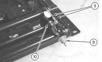
Illustration 5
g00871994
7. Disconnect harness assemblies (9) and hose assembly (10) from air valve (8).
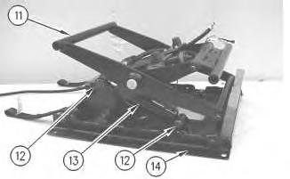
Illustration 6
g00872007
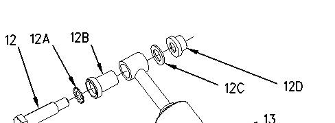
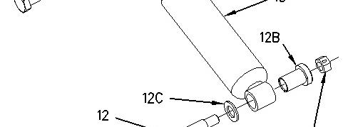

Illustration 7 g00897454
8. Raise scissor assembly (11) and install blocking in order to prevent scissor assembly (11) from falling.
9. Remove bolts (12) in order to remove shock absorber (13) from scissor assembly (11) and housing assembly (14).
10. Remove bearings (12B) from shock absorber (13).
Note: Illustration 7 shows the location of lockwasher (12A), bearings (12B), washers (12C), nut (12D), and locknut (12E).
11. Repeat Steps 9 and 10 if the seat is equipped with a shock absorber on the opposite side.
Illustration 8
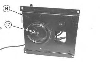
Illustration 9
g00872029
12. Remove shaft (15) in order to remove toggle assembly (16) from scissor assembly (11).
13. Remove screw (17) in order to disconnect spring assembly (18) from housing assembly (14).
Illustration 10
g00872031
14. Remove shaft assemblies (19) in order to remove scissor assembly (11) from housing assembly (14) and tether straps (11A).
Illustration 11
15. Remove shaft (20) in order to remove toggle assembly (21) from scissor assembly (11).
12
Personal injury can result from being struck by parts propelled by a released spring force.
Make sure to wear all necessary protective equipment.
Follow the recommended procedure and use all recommended tooling to release the spring force.
16. Remove hose assembly (22) and bolt (23) in order to remove spring assembly (18) from scissor assembly (11).
13
17. Remove bolts (24) in order to remove compressor assembly (25) from scissor assembly (11).
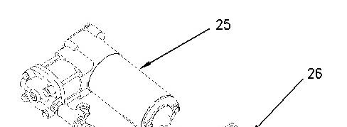
Illustration 14 g00891451 18. Remove compressor assembly (25) from mount (26).
Copyright 1993 - 2023 Caterpillar Inc. All Rights Reserved. Private Network For SIS Licensees.
Fri May 19 11:55:18 UTC+0530 2023
Product: TRACK LOADER
Model: 973 TRACK LOADER 32Z
Configuration: 973 TRACK LOADER / HIGH DRIVE / 32Z00001-UP (MACHINE) POWERED BY 3306 ENGINE
Disassembly and Assembly
Comfort Series Seat For Caterpillar Machines
Media Number -RENR2165-12 Publication Date -01/10/2013 Date Updated -31/10/2013
Air Suspension With System Air - Assemble
SMCS - 7324-016-AJ
Assembly Procedure Table 1 Tools Needed
- Loctite LB 8632 Silicone Lubricant (1)
- Loctite LB 8104 Silicone Lubricant (2)
- Loctite LB 8801 Silicone Lubricant (3)
- Loctite LB Superlube (4)
(1) North America (2) EAME (3) Asia Pacific Division (4) South America
1. Check the condition of all parts of the air suspension. If any of the parts are worn or damaged, install new parts.
This is the sample of the manual
Click on the download link for complete Manual

Illustration 1
Typical Example
g00275862
2. Position slider track (31) on upper housing (6). Install bolt (33), two bolts (32) and the washers. Tighten bolts (33) and (32) to a torque of 30 ± 7 N·m (22 ± 5 lb ft). Install locknut (30) and the washer. Tighten locknut (30) to a torque of 40 ± 8 N·m (30 ± 6 lb ft).
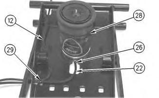
Illustration 2
g00275860
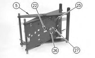
Illustration 3
g00275858
3. Position air spring (28) on scissor assembly (5). Apply Tooling (A) to the threads of bolt (27). Install bolt (27) that holds the air spring to scissor assembly (5). Tighten bolt (27) to a torque of 40 ± 8 N·m (30 ± 6 lb ft).