

Product: WHEEL LOADER
Model: 966K WHEEL LOADER PBG
Configuration: 966K Wheel Loader PBG00001-UP (MACHINE) POWERED BY C9.3 Engine
Disassembly and Assembly
966K and 972K Wheel Loaders Machine Systems
Media Number -KENR5833-01
Publication Date -01/03/2011
Accumulator (Steering, Pilot) - Remove and Install
SMCS - 4331-010; 5077-010
Removal Procedure
Start By:
a. Release hydraulic system pressure.
b. Hydraulic tank oil - retain.
Hot oil and components can cause personal injury.
Do not allow hot oil or components to contact skin.
Date Updated -21/03/2016
i04081875
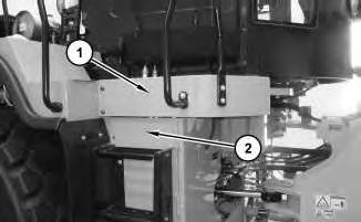
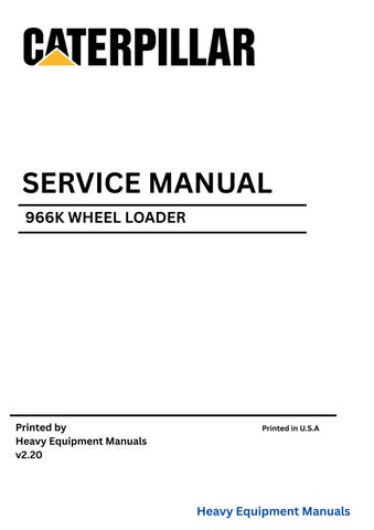
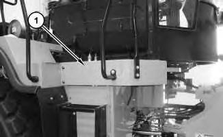
Illustration 1
1. Remove platform (1). Open door (2).
g02290360
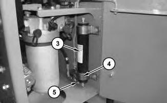
Illustration 2
g02290434
2. Disconnect fitting (5). Remove clamps (4) and accumulator (3).
Installation Procedure
1. Install accumulator (3) in the reverse order of the removal.
Copyright 1993 - 2019 Caterpillar Inc. All Rights Reserved. Private Network For SIS Licensees.
Product: WHEEL LOADER
Model: 966K WHEEL LOADER PBG
Configuration: 966K Wheel Loader PBG00001-UP (MACHINE) POWERED BY C9.3 Engine
Disassembly and Assembly
966K and 972K Wheel Loaders Machine Systems
Media Number -KENR5833-01
Publication Date -01/03/2011
Date Updated -21/03/2016
i04072969
Air
Pump (Variable Pitch Fan) - Remove and Install
SMCS - 107P-HFN
Removal Procedure
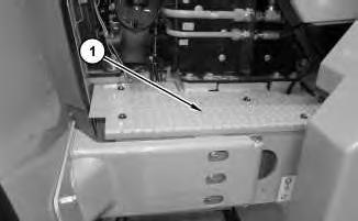
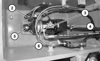
Illustration 1 g02283293
1. Remove cover (1).
This is the sample of the manual
Click on the download link for complete manual
2
2. Disconnect harnessassemblies(2), hose assembly (3), hose (4), bolts (5). Remove air pump (6).
Installation Procedure
1. Install air pump (6) in the reverse order of the removal.
Copyright 1993 - 2019 Caterpillar Inc. All Rights Reserved. Private Network For SIS Licensees. Wed Dec 18 11:04:28 UTC+0530 2019
Product: WHEEL LOADER
Model: 966K WHEEL LOADER PBG
Configuration: 966K Wheel Loader PBG00001-UP (MACHINE) POWERED BY C9.3 Engine
Disassembly and Assembly
966K and 972K Wheel Loaders Machine Systems
Media Number -KENR5833-01 Publication Date -01/03/2011
Updated -21/03/2016
i05667489
Blower Motor (Air Conditioner and Heater) - Remove and Install
SMCS - 7304-010-FM; 7309-010-FM; 7309-011-FM; 7311-010-FM; 7320-010-FM
Removal Procedure
Start By:
a. Remove the seat.
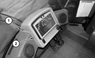
Illustration 1
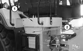
1. Remove four screws (1) and lower display assembly (2) out of the way.
2
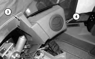
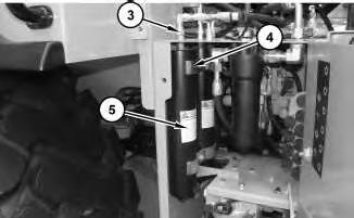
2. Remove eight screws (3) and air duct (4).
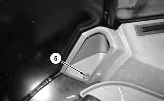
Illustration 3
3. Remove screw(5).
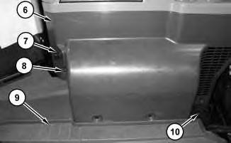
Illustration 4
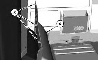
4. Remove holder (10). Remove four screws (8). Fold floor mat (9) out of the way. Carefully remove panel (6). There are three locking tabs(X) at the top on the opposite side of panel (6). Disconnect the harnessassembly for auxiliary power port (7).
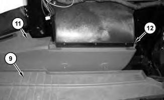
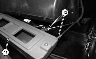
5. Remove two screws (12). Fold floor mat (9) back and slide duct (11) out in order to disconnect harness assemblies(13). Remove air duct (11).
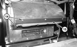
Illustration 8
6. Remove six screws (14) and lower blower motor support bracket (15).
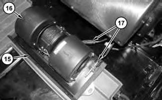
Illustration 9
7. Disconnect harnessassemblies(17). Separate blower motor (16) from blower motor support bracket (15).
Installation Procedure
1. Install blower motor (16) in the reverse order of the removal. Copyright 1993 - 2019 Caterpillar Inc.
For SIS
Wed Dec 18 11:19:07 UTC+0530 2019
Product: WHEEL LOADER
Model: 966K WHEEL LOADER PBG
Configuration: 966K Wheel Loader PBG00001-UP (MACHINE) POWERED BY C9.3 Engine
Disassembly and Assembly
966K and 972K Wheel Loaders Machine Systems
Media Number -KENR5833-01 Publication Date -01/03/2011 Date Updated -21/03/2016
Brake Accumulator - Remove and Install
SMCS - 4263-010
Removal Procedure
Start By:
A. System pressure release.
B. Hydraulic oil - retain.
Hot oil and components can cause personal injury.
Do not allow hot oil or components to contact skin.
i06159178
1
1. Remove platform (1) . Open door (2) .
2
Note: As anoption, one of the brake accumulatorsmay be located on the outside of the step compartment.
2. Disconnect all hose assemblies(3) . Remove clamps(4) and brake accumulators (5) .
Installation Procedure
1. Install brake accumulators (5) in the reverse order of the removal.
Product: WHEEL LOADER
Model: 966K WHEEL LOADER PBG
Configuration: 966K Wheel Loader PBG00001-UP (MACHINE) POWERED BY C9.3 Engine
Disassembly and Assembly
966K and 972K Wheel Loaders Machine Systems
Media Number -KENR5833-01
Publication Date -01/03/2011
Brake Control Valve (Parking) - Assemble
SMCS - 4282-016
Assembly Procedure

Illustration 1
Date Updated -21/03/2016
i04077809
g02286096
1. Install cartridge assembly (3). Tighten cartridge assembly (3) to the following torque 27 ± 1.35 N·m (20± 1lb ft). Install coil assembly (2). Install nut (1). Tighten nut (1) to the following torque 6.1 ± 0.7 N·m (54 ± 6 lb in)
End By:
a. Install the parking brake control valve.
Copyright 1993 - 2019 Caterpillar Inc. All Rights Reserved. Wed Dec 18 11:10:40 UTC+0530 2019
Product: WHEEL LOADER
Model: 966K WHEEL LOADER PBG
Configuration: 966K Wheel Loader PBG00001-UP (MACHINE) POWERED BY C9.3 Engine
Disassembly and Assembly
966K and 972K Wheel Loaders Machine Systems
Media Number -KENR5833-01
Publication Date -01/03/2011 Date Updated -21/03/2016
Brake Control Valve (Parking) - Disassemble
SMCS - 4282-015
Disassembly Procedure
Start By:
a. Remove the parking brake control valve.
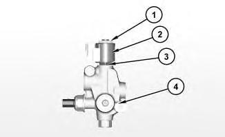
Illustration 1
g02286096
1. Remove nut (1), coil assembly (2), and cartridge assembly (3) from control valve (4).
i04074529
Product: WHEEL LOADER
Model: 966K WHEEL LOADER PBG
Configuration: 966K Wheel Loader PBG00001-UP (MACHINE) POWERED BY C9.3 Engine
Disassembly and Assembly
966K and 972K Wheel Loaders Machine Systems
Media Number -KENR5833-01
Publication Date -01/03/2011
Brake Control Valve (Parking) - Remove and Install
SMCS - 4282-010
Removal Procedure
Hot oil and components can cause personal injury.
Do not allow hot oil or components to contact skin.
Release the hydraulic system pressure.
Date Updated -21/03/2016
i04073650
2. Use two people in order to remove platform (1).
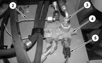
3. Disconnect tube assembly (2), harness assemblies (5), and hose assemblies (3). Remove control valve (4).
Installation Procedure
1. Install control valve (4) in the reverse order of the removal.
Product: WHEEL LOADER
Model: 966K WHEEL LOADER PBG
Configuration: 966K Wheel Loader PBG00001-UP (MACHINE) POWERED BY C9.3 Engine
Disassembly and Assembly
966K and 972K Wheel Loaders Machine Systems
Media Number -KENR5833-01 Publication Date -01/03/2011 Date Updated -21/03/2016
Brake Control Valve (Service) - Assemble
SMCS - 4265-016
Assembly Procedure
Table 1 RequiredTools
i02310953
Note: Cleanliness is an important factor. Before assembly, all partsshould be thoroughly cleaned in cleaning fluid. Allow the parts to air dry. Wiping cloths or rags should not be used to dry parts. Lint may be deposited on the partswhich may cause later trouble. Inspect all parts. If any parts are worn or damaged, use new parts for replacement.

Illustration 1
1. Install spool (20) into valve body (15).
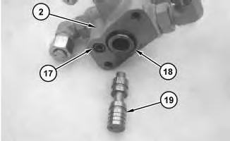
Illustration 2
2. Install O-ring seals (17) and (18).
3. Install spool (19) into valve body (2).
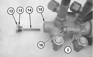
Illustration 3
Personal injury can result from being struck by parts propelled by a released spring force.
Make sure to wear all necessary protective equipment.
Follow the recommended procedure and use all recommendedtooling to release the spring force.
4. Apply Tooling (A) to bolts (16). Use bolts (16) to secure valve body (15) to valve body (2).
5. Install O-ring seal (13) on plug (12).
6. Install spring (14) and plug (12) into valve body (15).
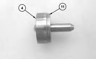
Illustration 4
7. Install shims (11) onto stop (4).
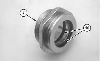
Illustration 5
8. Install seals (10) into retainer (7).
6
9. Install plunger (9) into retainer (7).
10. Install O-ring seal (8) onto retainer (7).

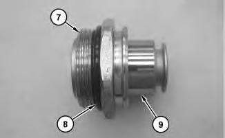
7
Personal injury can result from being struck by parts propelled by a released spring force.
Make sure to wear all necessary protective equipment.
Follow the recommended procedure and use all recommendedtooling to release the spring force.
11. Install spring (3), stop (4), spring (5), spring (6), and retainer (7) into valve body (2).
8
12. Install boot (1).
End By:
a. Install the brake control valve. Refer to Disassembly and Assembly, "Brake Control Valve (Service)Install".
Copyright 1993 - 2019 Caterpillar Inc. All Rights Reserved. Private Network For SIS Licensees.
Wed Dec 18 11:09:45 UTC+0530 2019
Product: WHEEL LOADER
Model: 966K WHEEL LOADER PBG
Configuration: 966K Wheel Loader PBG00001-UP (MACHINE) POWERED BY C9.3 Engine
Disassembly and Assembly
966K and 972K Wheel Loaders Machine Systems
Media Number -KENR5833-01 Publication Date -01/03/2011 Date Updated -21/03/2016
Brake Control Valve (Service) - Disassemble
SMCS - 4265-015
Disassembly Procedure
Start By:
i02310891
a. Remove the brake control valve. Refer to Disassembly and Assembly, "Brake Control Valve (Service) - Remove".
Note: Cleanliness is an important factor. Before the disassembly procedure, the exterior of the component should be thoroughly cleaned. This will help to prevent dirt from entering the internal mechanism.
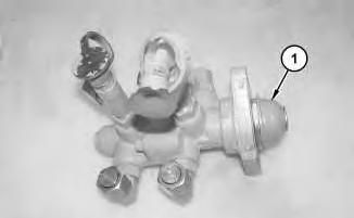
Illustration 1
1. Remove boot (1).
g01157403
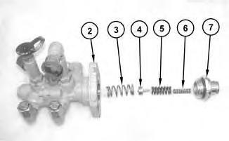
2
Personal injury can result from being struck by parts propelled by a released spring force.
Make sure to wear all necessary protective equipment.
Follow the recommended procedure and use all recommendedtooling to release the spring force.
2. Remove retainer (7) from valve body (2).
3. Remove spring (6), spring (5), stop (4), and spring (3) from valve body (2).
3
4. Remove O-ring seal (8) from retainer (7).
5. Remove plunger (9) from retainer (7).
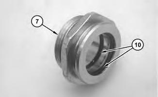
Illustration 4
6. Remove seals (10) from retainer (7).
Illustration 5
7. Remove shims(11) from stop (4).
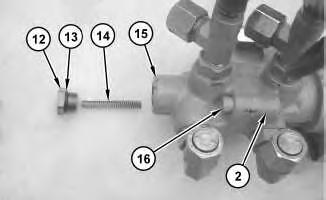
Illustration 6
Personal injury can result from being struck by parts propelled by a released spring force.
Make sure to wear all necessary protective equipment.
Follow the recommended procedure and use all recommendedtooling to release the spring force.
8. Remove plug (12), O-ring seal (13), and spring (14) from valve body (15).
9. Remove bolts (16) in order to separate valve body (15) from valve body (2).
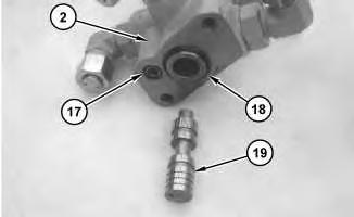
Illustration 7
10. Remove O-ring seals (17) and (18) from valve body (2).
11. Remove spool (19) from valve body (2).
This is the sample of the manual
Click on the download link for complete manual
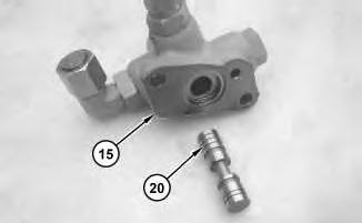
Illustration 8
12. Remove spool (20) from valve body (15).
g01157416
Copyright 1993 - 2019 Caterpillar Inc. All Rights Reserved. Private Network For SIS Licensees.
Wed Dec 18 11:09:28 UTC+0530 2019