
Note: Use Bookmarks panel to navigate

Product: WHEEL LOADER
Model: 966F II WHEEL LOADER 9YJ
Configuration: 966F Series II Wheel Loader 9YJ00001-UP (MACHINE) POWERED BY 3306 Engine
Disassembly and Assembly
3306 VEHICULAR ENGINE FOR 966D WHEEL LOADER
Media Number -SENR2149-00
Hood
SMCS - 7251-11; 7251-12
Remove Hood
Publication Date -01/04/1981
Date Updated -11/10/2001
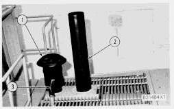
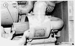
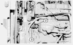
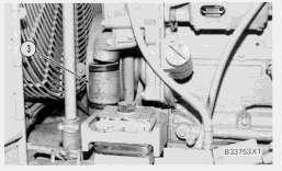
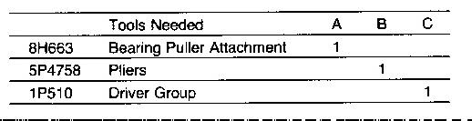
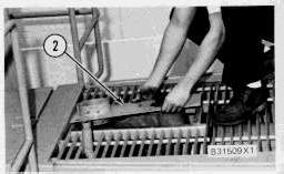
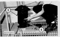
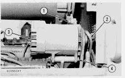
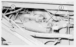
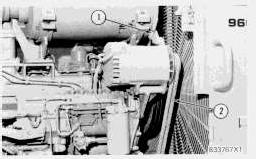
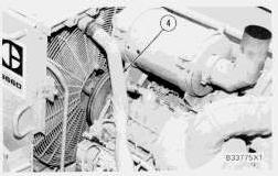
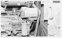
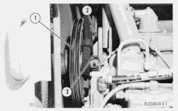
1. Remove the bolts and exhaust pipe (2).
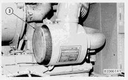
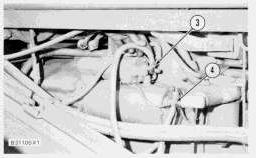
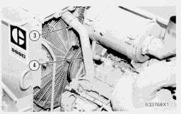
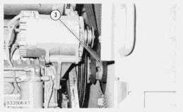
2. Loosen the clamp and disconnect hose (3) from the tube.
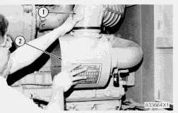
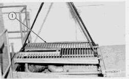
3. Loosen the clamp that holds the precleaner in place. Remove precleaner (1) from the hood.
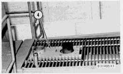
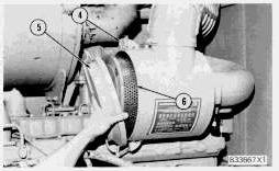
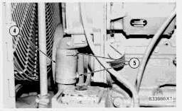
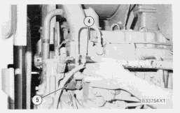
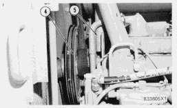
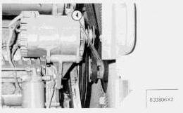
4. Remove the bolts and plate (4).
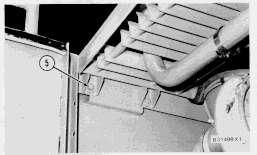
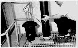
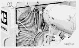
5. Remove bolts (5) that hold the hood in place.
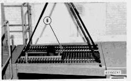
6. Fasten a hoist to hood (6) and remove it. The weight of the hood is 44 kg (98 lb.).
Install Hood
3. Put precleaner (3) and hose (4) in place and install the clamps.
4. Install exhaust pipe (5) and the bolts on the hood.
Copyright 1993 - 2022 Caterpillar Inc. All Rights Reserved. Private Network For SIS Licensees.
Wed Dec 14 00:29:24 UTC+0530 2022
Product: WHEEL LOADER
Model: 966F II WHEEL LOADER 9YJ
Configuration: 966F Series II Wheel Loader 9YJ00001-UP (MACHINE) POWERED BY 3306 Engine
Disassembly and Assembly
3306 VEHICULAR ENGINE FOR 966D WHEEL LOADER
Media Number -SENR2149-00
Alternator
SMCS - 1405-11; 1405-12
Remove Alternator
Publication Date -01/04/1981
1. Disconnect the wires at the batteries.
2. Disconnect wires (1) and (2) from the alternator.
3. Loosen lower nut (3) on the adjusting rod.
4. Remove vee belts (6) from the alternator pulley.
5. Remove bolts (4) and (5) and remove the alternator.
Install Alternator
Date Updated -11/10/2001
This is the sample of the manual
Click on the download link for complete manual
1. Put alternator (3) in position and install bolts (1) and (4).
2. Put vee belts (2) in position on the pulley.
3. Use a belt tension gauge such as Borroughs Tool Company Part No. BT-33-72C or an equivalent and make an adjustment of vee belts (2). Measure the belt nearest the radiator. Tighten new belts until the gauge indication is 120 ± 5. Tighten the bolts (7) that hold the alternator in position. Operate the engine at high idle for a minimum of 30 minutes after Steps 4 and 5. Make another adjustment of the belt tension. The correct gauge indication for used belts is 90 ± 10.
4. Connect wires (5) and (6) to the alternator.
5. Connect the wires to the battery.
Wed Dec 14 00:29:37 UTC+0530 2022
Product: WHEEL LOADER
Model: 966F II WHEEL LOADER 9YJ
Configuration: 966F Series II Wheel Loader 9YJ00001-UP (MACHINE) POWERED BY 3306 Engine
Disassembly and Assembly
3306 VEHICULAR ENGINE FOR 966D WHEEL LOADER
Media Number -SENR2149-00
Electric Starting Motor
Publication Date -01/04/1981
Date Updated -11/10/2001
SMCS - 1453-11; 1453-12
Remove Electric Starting Motor
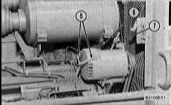
1. Disconnect the battery cables from the batteries.
2. Disconnect wires (1) and (2) from the starting motor.
3. Remove bolts (3) and remove starting motor (4). The weight of the starting motor is 32 kg (70 lb.).
Install Electric Starting Motor
1. Put the gasket in position and install starting motor (2) in position and install bolts (1).
2. Connect wires (3) and (4) to the starting motor and to the solenoid.
3. Connect the battery cables to the batteries.
Copyright 1993 - 2022 Caterpillar Inc. All Rights Reserved. Private Network For SIS Licensees. Wed Dec 14 00:29:49 UTC+0530 2022
Product: WHEEL LOADER
Model: 966F II WHEEL LOADER 9YJ
Configuration: 966F Series II Wheel Loader 9YJ00001-UP (MACHINE) POWERED BY 3306 Engine
Disassembly and Assembly
3306 VEHICULAR ENGINE FOR 966D WHEEL LOADER
Media Number -SENR2149-00 Publication Date -01/04/1981 Date Updated -11/10/2001
Air Conditioner Compressor
SMCS - 1357-10
Remove And Install Air Conditioner Compressor
Always wear goggles when the air conditioning system is opened. This system is charged with Freon-12 (CCL2F2-Dichlorodifluoromethane) which is not toxic or flammable. But there is a reason for caution. When Freon-12 makes contact with a flame, lethal phosgene gas is made. INHALING FREON THROUGH A LIGHTED CIGARETTE CAN CAUSE VIOLENT ILLNESS. This system is under pressure at all times, engine running or not. HEAT MUST NEVER BE PUT ON A CHARGED SYSTEM. See AIR CONDITIONING AND HEATING SERVICE MANUAL Form No. SENR7454 for more information on procedures and safety requirements on removal and installation of lines and refrigerant from the system.
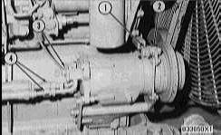
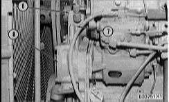
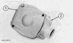
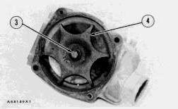
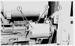
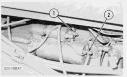
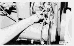
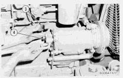
1. Remove plate (3) and disconnect hose assemblies (4) from the air conditioner compressor.
2. Put plate (3) back in position on the compressor to keep out foreign material.
3. Loosen adjusting bolt (1) and remove vee belt (2).
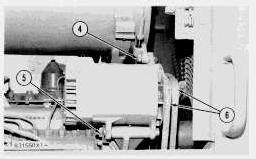
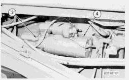
4. Disconnect the wires from the compressor.
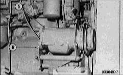
5. Remove bolts (6) and remove compressor (5).
NOTE: The following steps are for installation of the air conditioning compressor.
6. Put the air conditioner compressor in position and install the bolts.
7. Connect wires (7) to the compressor.
8. Install the belt on the compressor. Make an adjustment of the belt. See MAINTENANCE GUIDE.
9. Put hose assemblies (4) in position and install plate (3).
10. See AIR CONDITIONING AND HEATING SERVICE MANUAL Form No. SENR7454 for correct procedure for evacuating and charging the system.
Wed Dec 14 00:30:03 UTC+0530 2022
Product: WHEEL LOADER
Model: 966F II WHEEL LOADER 9YJ
Configuration: 966F Series II Wheel Loader 9YJ00001-UP (MACHINE) POWERED BY 3306 Engine
Disassembly and Assembly
3306 VEHICULAR ENGINE FOR 966D WHEEL LOADER
Media Number -SENR2149-00
Fan
SMCS - 1356-11; 1356-12
Remove Fan
Publication Date -01/04/1981
1. Drain the coolant from the cooling system.
Date Updated -11/10/2001
4. Remove fan guards (5) from the radiator.
NOTICE
Do not damage the radiator core with fan (6).

5. Remove the bolts that hold fan (6) to the adapter. Put the fan carefully in position in the radiator as shown. The weight of the fan is 39 kg (85 lb.).
6. Remove adapter (7) from the pulley.
7. Remove fan (6) from the radiator.
Install Fan
NOTICE
Do not damage the radiator core with fan (1).
1. Put fan (1) in position in the radiator.
2. Install adapter (2) on the fan drive pulley. Make sure the vee belts are on the pulley.
3. Install fan (1) on the adapter.

4. Put guards (3) in position on the radiator.
5. Install the gasket and elbow (4). Connect the hose at the top.

6. Put vee belts (6) on the alternator. Tighten the nut on bolt (5). Use a belt tension gauge such as Borroughs Tool Company Part No. BT-33-72C or an equivalent and make an adjustment of the vee belts. Measure the belt nearest the radiator. Tighten new belts until the gauge indication is 534 ± 22 N (120 ± 5 lb.). Tighten the bolts that hold the alternator in position. Operate the engine at high idle for a minimum of 30 minutes. Make another adjustment of the belt tension. The correct gauge indication for used belts is 400 ± 44 N (90 ± 10 lb.).
Copyright 1993 - 2022 Caterpillar Inc.
All Rights Reserved.
Private Network For SIS Licensees.
Wed Dec 14 00:30:16 UTC+0530 2022
Product: WHEEL LOADER
Model: 966F II WHEEL LOADER 9YJ
Configuration: 966F Series II Wheel Loader 9YJ00001-UP (MACHINE) POWERED BY 3306 Engine
Disassembly and Assembly
3306 VEHICULAR ENGINE FOR 966D WHEEL LOADER
Media Number -SENR2149-00
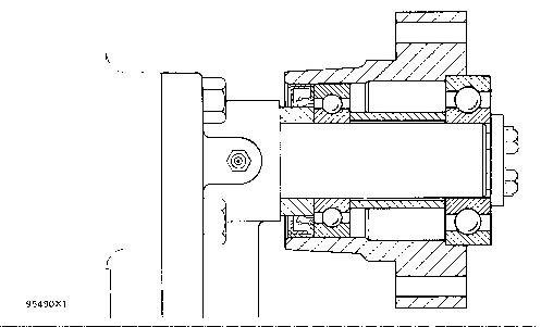
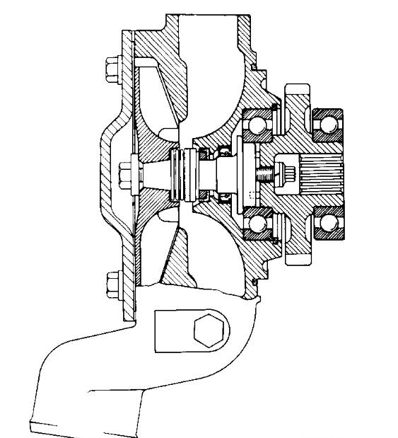
Fan Drive
Publication Date -01/04/1981
SMCS - 1359-16; 1359-11; 1359-12; 1359-15
Remove Fan Drive
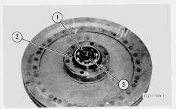
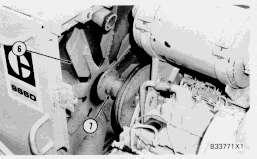
1. Loosen the nut on rod (1).
2. Remove vee belts (2) from the pulleys.
Date Updated -11/10/2001
NOTICE
Do not damage the radiator core with the fan.
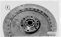
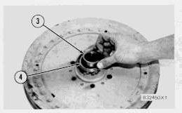
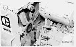
3. Fasten a hoist to the fan and adapter (3). Remove the bolts that hold adapter (3) to the fan drive.
4. Carefully lean the fan against the radiator core.
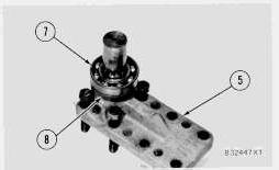
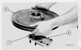
5. Fasten a hoist to pulley and fan drive (4).
6. Remove the bolts that hold the fan drive to the cylinder head and to support bracket (5). Remove the fan drive.
Install Fan Drive
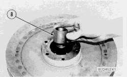
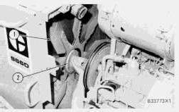
1. Put fan drive (1) in position and install bolts (2) and (3).
2. Put adapter (4) and the fan in position and install the bolts. Make sure the vee belts are on or behind the pulley.
3. Put the vee belts in position on the pulleys.
4. Use a belt tension gauge such as Borroughs Tool Company Part No. BT-33-72C or an equivalent and make an adjustment of vee belts. Measure the belt nearest the radiator. Tighten new belts until the gauge indication is 534 ± 22N (120 ± 5 lb.). Tighten the bolts that hold the alternator in position. Operate the engine at high idle for a minimum of 30 minutes. Make another adjustment of the belt tension. The correct gauge indication for used belts is 400 ± 44N (90 ± 10 lb.).