

Product: TRACK LOADER
Model: 963K TRACK LOADER LBL
Configuration: 963K TRACK-TYPE LOADER LBL00001-UP (MACHINE) POWERED BY C7.1 Engine
Disassembly and Assembly
963K Track Type Loader Engine Supplement
Media
-30/01/2020
Aftercooler - Remove and Install
SMCS - 1063-010
Removal Procedure
Start By: a. Remove the cooling system package.
1
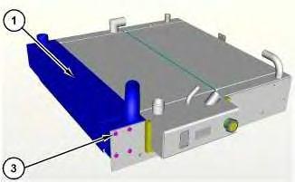
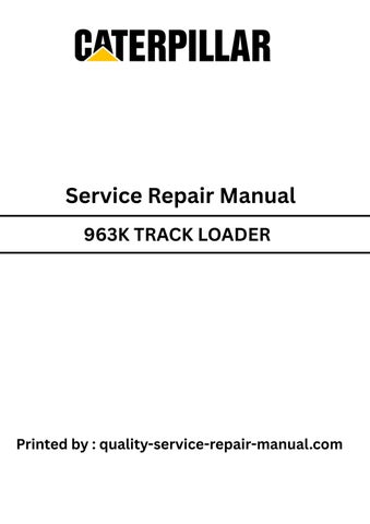
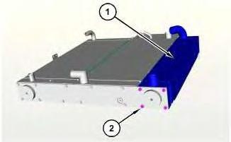
Illustration 2
1. Remove bolts (2) and bolts (3) from each end of aftercooler (1).
2. Remove aftercooler (1).
Installation Procedure
1. Install aftercooler (1) in the reverse order of removal.
Copyright 1993 - 2025 Caterpillar Inc. All Rights Reserved. Private Network For SIS Licensees.
Wed Jan 8 14:59:06 UTC+0530 2025
Product: TRACK LOADER
Model: 963K TRACK LOADER LBL
Configuration: 963K TRACK-TYPE LOADER LBL00001-UP (MACHINE) POWERED BY C7.1 Engine
Disassembly and Assembly
963K Track Type Loader Engine Supplement
Media Number -UENR0006-01 Publication Date -01/01/2020
Air Cleaner - Remove and Install
SMCS - 1051-010
Removal Procedure

Updated -30/01/2020
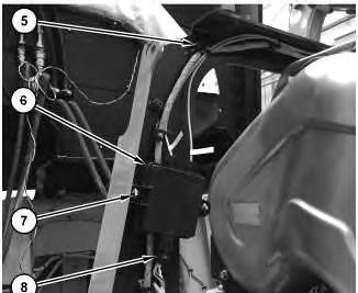
2. Disconnect harness assemblies (4) and (7). Disconnect hoses (5) and (6). Remove bolts (3) and air cleaner (8).
Installation Procedure
1. Install air cleaner (8) in the reverse order of removal.
a. Tighten bolts (3) to a torque of 10 ± 2 N·m (89 ± 18 lb in).
Copyright 1993 - 2025 Caterpillar Inc. All Rights Reserved. Private Network For SIS Licensees. Wed Jan 8 14:58:50 UTC+0530 2025
This is the sample of the manual
Click on the download link for complete Manual
Product: TRACK LOADER
Model: 963K TRACK LOADER LBL
Configuration: 963K TRACK-TYPE LOADER LBL00001-UP (MACHINE) POWERED BY C7.1 Engine
Disassembly and Assembly
963K Track Type Loader Engine Supplement
Alternator - Remove and Install
SMCS - 1405-010
Removal Procedure
Bodily contact with electrical potential can cause bodily injury or death.
To avoid the possibility of injury or death, ensure that the main power supply has been disconnected before performing any maintenance or removing any modules.
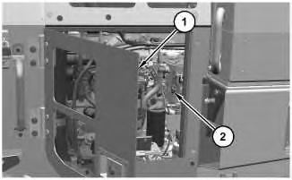
1
g06468298 Right side view of the machine.
2. Turn battery disconnect switch (2) to the OFF position.
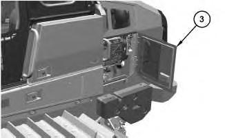
Illustration 2
Left side view of the machine.
3. Open door assembly (3).
g06469405
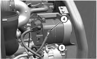
Illustration 3
Components are hidden for clarity purpose.
g06469407
4. Remove bolt (4) and disconnect ground strap (5).
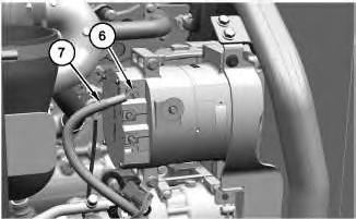
Illustration 4
g06477850
5. Remove nut (6) and disconnect cable assembly (7).
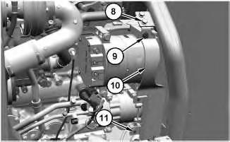
Illustration 5
6. Remove bolts (8), (9), and (11). Remove guard assembly (10).
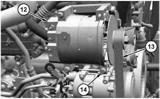
Illustration 6
g06480132
7. Remove belt (13). Refer to Operation and Maintenance Manual, "Belt - Inspect/Replace" for the correct procedure.
8. Remove bolts (14) and alternator (12).
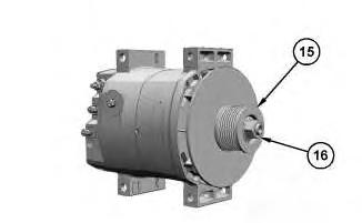
Illustration 7
9. Remove nut (16) and pulley (15).
Installation Procedure
1. Install alternator (12) in the reverse order of removal.
a. Tighten nut (16) to a torque of 102 ± 7 N·m (75 ± 5 lb ft).
b. Tighten bolts (14) to a torque of 65.5 ± 7.5 N·m (48 ± 6 lb ft).
c. Tighten bolt (9) to a torque of 65.5 ± 7.5 N·m (48 ± 6 lb ft).
d. Tighten nut (6) to a torque of 6 ± 1 N·m (53 ± 9 lb in).
e. Tighten bolt (4) to a torque of 14 ± 2 N·m (124 ± 18 lb in).
Copyright 1993 - 2025 Caterpillar Inc.
All Rights Reserved.
Private Network For SIS Licensees.
Wed Jan 8 14:51:14 UTC+0530 2025
Product: TRACK LOADER
Model: 963K TRACK LOADER LBL
Configuration: 963K TRACK-TYPE LOADER LBL00001-UP (MACHINE) POWERED BY C7.1 Engine
Disassembly and Assembly
963K Track Type Loader Engine Supplement
Battery - Remove and Install
SMCS - 1401-010
Removal Procedure
Bodily contact with electrical potential can cause bodily injury or death.
To avoid the possibility of injury or death, ensure that the main power supply has been disconnected before performing any maintenance or removing any modules.
Personal injury can result from failure to disconnect the battery.
First, disconnect the negative battery cable. Then, disconnect the positive battery cable.
A positive power lead can cause sparks if the battery is not disconnected. Sparks can possibly result in battery explosion or fire.
Note: Put Identification marks on all lines, on all hoses, on all wires, and on all tubes for installation purposes.
Illustration 1
Right side view of the machine.
1. Open door assembly (1).
g06468298
2. Turn the battery disconnect switch (2) to the OFF position.

Illustration 2
3. Open door assemblies (3) and (4).
g06468306
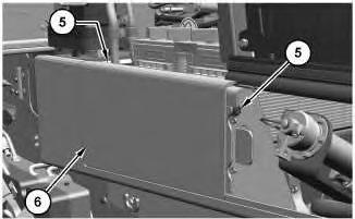
Illustration 3
4. Remove bolts (5) and panel assembly (6).
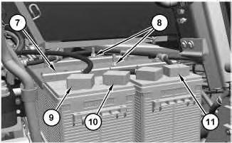
Illustration 4
Components are hidden for clarity purpose.
g06474794
Note: Always disconnect the negative battery cable before the positive battery cable.
5. Disconnect cable assemblies (9) and (11).
6. Remove cable assembly (10).
7. Remove nuts (8). Position bracket assembly (7) along with the cable assemblies (9), (10), and (11) out of the way.
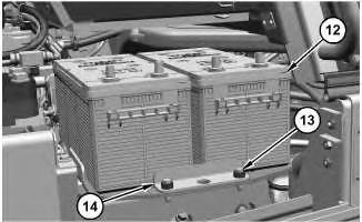
Illustration 5
8. Remove bolts (13) and plate (14).
g06468315
9. Use two people to remove battery (12). The weight of battery (12) is approximately 44 kg (97 lb) each. Remove battery (12). Repeat for the other battery.
Installation Procedure
1. Install batteries (12) in the reverse order of removal.
a. Tighten nuts (8) to a torque of 30 ± 3 N·m (266 ± 27 lb in).
b. Tighten the nuts of cable assemblies (9), (10), and (11) to a torque of 7.2 ± 1.6 N·m (64 ± 14 lb in).
Copyright 1993 - 2025 Caterpillar Inc. All Rights Reserved.
Network For SIS Licensees.
Wed Jan 8 14:50:46 UTC+0530 2025
Product: TRACK LOADER
Model: 963K TRACK LOADER LBL
Configuration: 963K TRACK-TYPE LOADER LBL00001-UP (MACHINE) POWERED BY C7.1 Engine
Disassembly and Assembly
963K Track Type Loader Engine Supplement
Media Number -UENR0006-01 Publication Date -01/01/2020 Date Updated -30/01/2020
Belt Tensioner - Remove and Install
SMCS - 1358-010
Removal Procedure
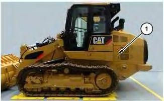
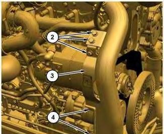
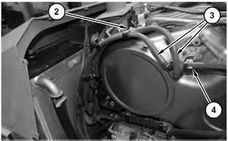
Illustration 2
g06470747 Components hidden for better clarity.
2. Remove bolts (4), bolts (2), and guard (3).
3. Remove the belt. Refer to Operation and Maintenance Manual, "Belts - Inspect/Replace" for the correct removal and installation procedure of the belt.
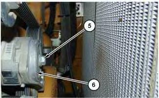
Illustration 3
4. Remove bolt (5) and belt tensioner (6).
Installation Procedure
g06272290
1. Install belt tensioner (6) in the reverse order of removal.
a. Tighten bolt (5) to a torque of 45 ± 5 N·m (33 ± 4 lb ft).
Wed Jan 8 14:52:08 UTC+0530 2025
Product: TRACK LOADER
Model: 963K TRACK LOADER LBL
Configuration: 963K TRACK-TYPE LOADER LBL00001-UP (MACHINE) POWERED BY C7.1 Engine
Disassembly and Assembly
963K Track Type Loader Engine Supplement
Clean Emissions Module - Remove and Install
SMCS - 1050-010; 7279-010
Removal Procedure
Table 1
Required Tooling
A - Loctite Nickel Anti-seize Lubricant -
Start By:
a. Partially tilt the cab.
b. Remove the engine enclosure.
1. Drain the coolant. Refer to Operation and Maintenance Manual, "Cooling System Coolant (ELC) - Change" for the correct draining and filling procedures.
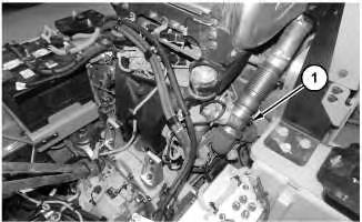
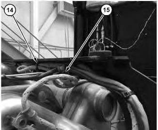
Illustration 1
2. Remove clamp (1) .
2
6.
3

4
7. Disconnect harness assembly (13).
8. Remove straps (9).
9. Remove bolts (10) , NOX sensor (11), and NOX sensor (12).
Note: Do not disconnect the plug when the NOX sensors are powered. The NOX sensors should be powered down for a minimum of 15 minutes before removal.
5
10. Remove straps (14), bolt (15), and position the harness assembly out of the way.
6
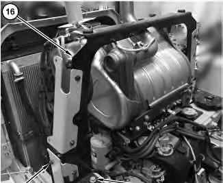
11. Remove bolt (17) and bolts (18). Repeat for the opposite side. Remove support assembly (16).
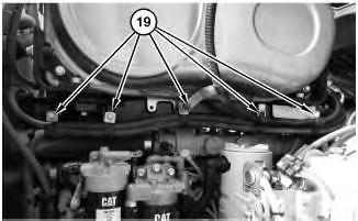
Illustration 7
12. Remove five bolts (19) and place hoses out of the way.
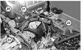
Illustration 8
13. Remove bolt (20) and nut (21). Remove bolts (22) and (23) (not shown).
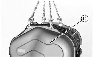
Illustration 9
g06124728
14. Attach a suitable lifting device to clean emissions module (24). The weight of clean emissions module (24) is approximately 127 kg (280 lb).
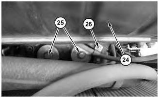
Illustration 10 g06124733
View is from above looking down between the cooling package and the clean emissions module.
15. Remove bolt (26), bolts (25), and clean emissions module (24).
Installation Procedure
1. Install clean emissions module (24) in the reverse order of removal.
a. Tighten bolts (25), (23), and (22) to a torque of 190 N·m (140 lb ft).
b. Tighten bolt (2) to a torque of 22 N·m (195 lb in).
c. Tighten clamp (1) to torque of 12 ± 1 N·m (106 ± 9 lb in) with a maximum wrench speed of 75 RPM.
Wed Jan 8 14:57:32 UTC+0530 2025
Product: TRACK LOADER
Model: 963K TRACK LOADER LBL
Configuration: 963K TRACK-TYPE LOADER LBL00001-UP (MACHINE) POWERED BY C7.1 Engine
Disassembly and Assembly
963K Track Type Loader Engine Supplement
Cooling System Package (Radiator, Aftercooler, Hydraulic Oil Cooler) - Remove and Install
SMCS - 1063-010; 1353-010; 1374-010
Removal Procedure
Start By:
a. Remove the engine enclosure.
b. Remove the grill.
Note: Cleanliness is an important factor. Before the disassembly procedure, clean the exterior of the component thoroughly to help to prevent dirt from entering the internal mechanism.
Note: Put identification marks on all lines, on all hoses, on all harness assemblies, and on all tubes for installation purposes. Plug all lines, hoses, and tubes to help prevent fluid loss and to help keep contaminants from entering the system.
NOTICE
Care must be taken to ensure that fluids are contained during performance of inspection, maintenance, testing, adjusting, and repair of the product. Be prepared to collect the fluid with suitable containers before opening any compartment or disassembling any component containing fluids.
Refer to Special Publication, NENG2500, "Dealer Service Tool Catalog" for tools and supplies suitable to collect and contain fluids on Cat® products.
Dispose of all fluids according to local regulations and mandates.
Personal injury can result from hot coolant, steam and alkali.
At operating temperature, engine coolant is hot and under pressure. The radiator and all lines to heaters or the engine contain hot coolant or steam. Any contact can cause severe burns.
Remove cooling system pressure cap slowly to relieve pressure only when engine is stopped and cooling system pressure cap is cool enough to touch with your bare hand.
Do not attempt to tighten hose connections when the coolant is hot, the hose can come off causing burns.
Cooling System Coolant Additive contains alkali. Avoid contact with skin and eyes.
Personal injury can result from hydraulic oil pressure and hot oil.
Hydraulic oil pressure can remain in the hydraulic system after the engine has been stopped. Serious injury can be caused if this pressure is not released before any service is done on the hydraulic system.
Make sure all of the work tools have been lowered to the ground, and the oil is cool before removing any components or lines. Remove the oil filler cap only when the engine is stopped, and the filler cap is cool enough to touch with your bare hand.
1. Drain the coolant into a suitable container for storage or disposal. Refer to Operation and Maintenance Manual, "Cooling System Coolant (ELC) - Change".
2. Drain the hydraulic system into a suitable container for storage or disposal. Refer to Operation and Maintenance Manual, "Hydraulic System Oil - Change".
3. Lower the rear power train guard. Refer to Disassembly and Assembly, "Power Train Guard - Remove and Install".
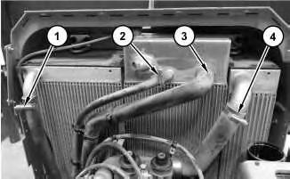
1
4. Disconnect hoses (1), (2), (3) and (4).
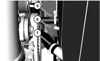
Illustration 2
5. Disconnect hose assembly (6) and hoses (5) and (7).
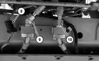
Illustration 3
6. Disconnect harness assembly (8) and hose assemblies (9) and (10).
This is the sample of the manual
Click on the download link for complete Manual
4
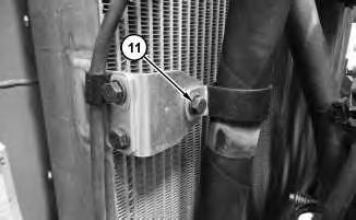
7. Remove bolt (11) and place hose and clamp assembly out of the way.
5
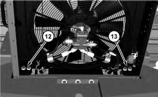
8. Remove bolts (12) and bolts (13).
9. Attach a suitable lifting device to radiator guard and support, the aftercooler, the hydraulic oil cooler, and radiator . The weight of radiator guard and support, aftercooler, hydraulic oil cooler, and radiator is approximately 454 kg (1000 lb)
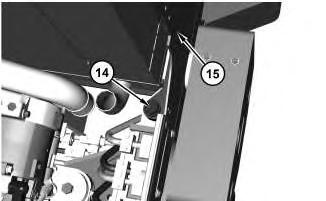
Illustration 6