

Product: TRACK LOADER
Model: 963C TRACK LOADER BBD
Configuration: 963C TRACK-TYPE LOADER TIER II BBD00001-UP (MACHINE) POWERED BY 3126B Engine
Disassembly and Assembly
Flexxaire Fan
Media Number -RENR3699-07
Publication Date -01/02/2012
Control System - Remove and Install
SMCS - 1356-010-YC
General Installation
Installation of the Mark I Control System
Date Updated -21/06/2016
i01739978
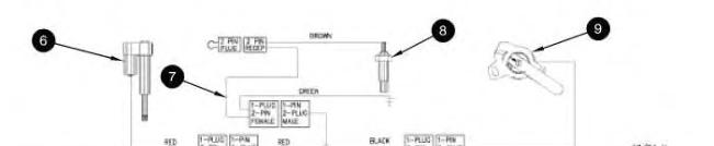
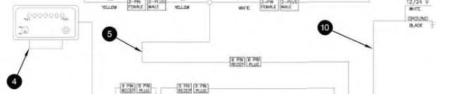
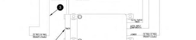
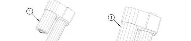
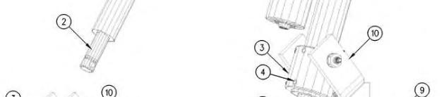
Illustration 1 g00564778
Mark I ControlSystem
(1) MarkI control box
(2) AUTO-purge timer
(3) Cable for remote display
(4) Remote display
(5) Pigtail
(6) Actuator
(7) Temperatureandgroundcable
(8) Temperaturesensor
(9) Positionsensor
(10) Power cable
1. Mount control box (1) in the operator'scompartment. The mounting location should meet the following criteria:
Minimal debris and vibration
Safe from water that is high pressure
Accessible for future adjustmentsor changes in setup
The control box should be mounted in a vertical position, and vibration mounts that are supplied with the controller should be installed.
2. AUTO-purge timer (2) is located near control box (1). Connect the end of the cable for AUTO-purge timer (2) to the plug end of the cable for the AUTO-purge timer on control box (1).
3. Cable for remote display (3) may not be required for all installations. Connect the end of the cable for remote display (3) to the plug end of AUTO-purge timer (2). Connect the plug end of cable for remote display (3) into the end of the pigtail for remote display (4).
4. Mount remote display (4) on the dash or another convenient location. The remote display should be visible and accessible to the operator. Connect the end of the cable for remote display (4) to the plug end of the cable for remote display (3).
5. Connect the end of pigtail (5) to the plug end of the cable for control box (1). Pigtail (5) splitsinto a harnesswith three connectors. One end goes to actuator (6). One end goesto temperature sensor (8). One end goes to position sensor (9).
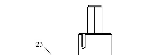
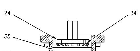
6. The following steps are for installation of actuator (6):

(1) Actuator
(2) Actuatorrod
(3) Actuatorcollar
(4) Setscrew
(5) Operator fork
(6) Hitch pin
(7) Mechanicalstop
(8) Positionsensor
(9) Alignment plate
(10) Actuatorclevis
a. Remove hitch pin (6).
b. Position operator fork (5) against mechanical stop (7).
c. Manually turn actuator rod (2) outward until the rod isfully extended. When the rod reaches the end of travel, the actuator motor can be felt turning.
d. Retract actuator rod (2) by the rotating actuator rod by 180 degrees. The actuator motor should not turn.
e. Slide actuator (1) through actuator collar (3). Verify that the actuator collar is oriented so that setscrews(4) are facing away from actuator clevis(10).
f. Retracting actuator rod (2) by 1/4 turn may be required in order to line up the hole in actuator rod (2) with the hole in operator fork (5).
g. Insert hitch pin (6) through operator fork (5) and actuator rod (2).
h. Verify that operator fork (5) is against mechanical stop (7). Make sure that the actuator motor is oriented in the correct position. The actuator motor must be clear of obstructions. Rotate the actuator in the collar prior to tightening setscrews (4).
i. Apply 9S-3263 Thread Lock Compound to setscrews(4) and install the setscrews. Tighten the setscrew to a torque of 16 N·m (12 lb ft).
Note: Do not tighten setscrews more than 1.5 threads below the surface.
j. Connect the end of the cable for the actuator to the red and yellow plug of pigtail (5).
7. Connect the end of temperature and ground cable (7) to the plug with green and black wires of pigtail (5). The ground wire (green) is secured with a bolt that threads in to the support arm of the fan assembly. The brown lead wire is connected to the top of temperature sensor (8).
8. Thread temperature sensor (8) into the engine block. An area that is close to the water temperature regulator is recommended. Temperature sensor (8) comeswith three thread adapters. The brown lead wire of temperature and ground cable (7) connects to the top of temperature sensor (8).
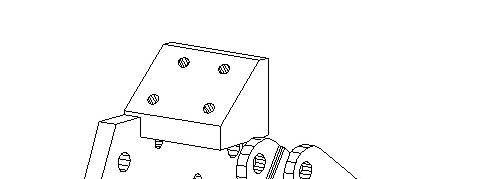
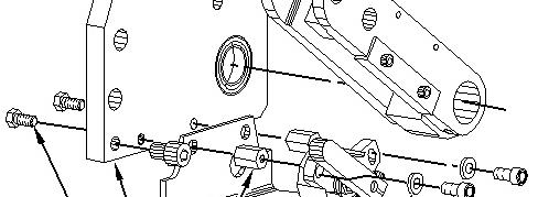

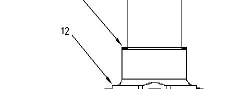
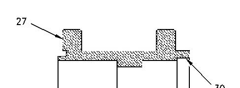
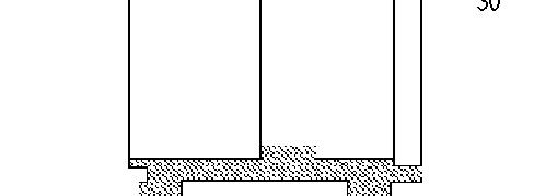
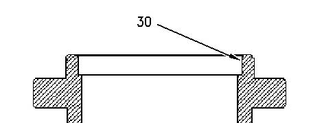
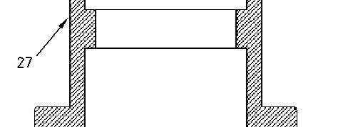
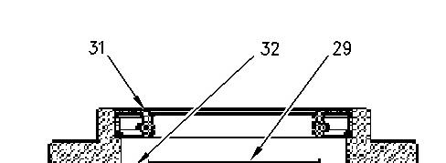
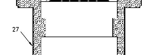
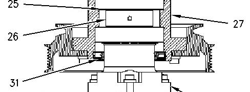
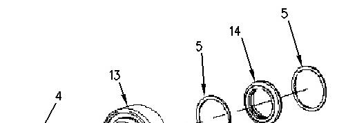
Illustration 3 g00918804
(1) Mounting bracketfor the positionsensor
(2) Bolt
(3) Alignment plate
(4) Mounting nut for the position sensor
(5) Positionsensor
(6) Washer
(7) Capscrew
9. The following steps are for installation of position sensor (9):
a. Place mounting bracket (1) for the position sensor against alignment plate (3).
b. Thread bolt (2) into mounting nut (4) for the position sensor through alignment plate (3) and position sensor mounting bracket (1). Tighten bolt (2) to a torque of 16.3 N·m (12.0 lb ft).
c. Place position sensor (5) in the correct location.
d. Put washer (6) on capscrew (7). Thread capscrew (7) into mounting nut (4) for the position sensor through position sensor (5).
e. Connect the plug end of the cable for position sensor (5) to the end of the pigtail.
10. Connect the plug end of power cable (10) to the end of the power cable for the control box.
This is the sample of the manual
Click on the download link for complete Manual
White wire - This wire connects to a 10 Amp fuse or to a circuit breaker. The power source that is being used must allow power to the control box when the engine is not running.
Black wire - This wire connects to the main disconnect or a different ground location.
Installation of the Mark III Control System
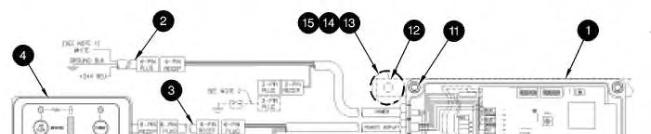
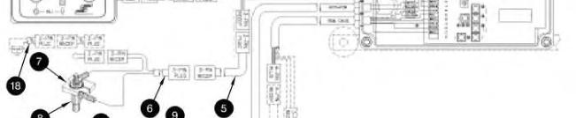

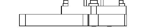
Illustration 4 g00573394
Mark IIIcontrol system
(1) MarkIII controlbox
(2) Power cable
(3) Extensioncable for remote display
(4) Remote display
(5) Extensioncable for temperature sensor
(6) Cable for temperature sensor
(7) Ground collar
(8) Temperaturesensor
(9) Extensioncable for actuator
(10) Actuator
(11) Screw
(12) Mounting bracket
(13) Vibration mount
(14) Washer
(15) Nut
(16) Cable for remote calibrator
(17) Remote calibrator
(18) Pressure switch
1. Mount control box (1) in the operator'scompartment. The mounting location should meet the following criteria:
Minimal debris and vibration
An area that is away from high pressure washes
Accessible for future adjustmentsand changes in setup
The control box should be mounted in a vertical position and the vibration mountsthat are supplied with the control box should be installed.
2. Install temperature sensor (8) with the NPT bushing that is supplied. The sensor should be installed in the water jacket of the engine. The most preferable location for the temperature sensor is near the coolant temperature regulator. This will allow the sensor to sense maximum water temperature.
3. Route extension cable for temperature sensor (5) from the control box to the temperature sensor. Connect cable for temperature sensor (6) to extension cable (5). Connect the black wire to the ground collar. Install the ground collar around the hex portion of the temperature sensor and tighten the clamping screw. Connect the white wire to the top of the temperature sensor.
4. Route extension cable for actuator (9) from the control box to the actuator.
5. Connect power cable (2).
Red wire - This wire connectsto a 10 Amp fuse or to a circuit breaker. The connection should be made to a circuit that is isolated during operation of the starter. This circuit should not be powered when the ignition key is in the OFF position.
Black wire - This wire connects to the main disconnect or a stable ground location.
6. Mount remote display (4) on the dash or another convenient location. The remote display should be visible and accessible to the operator. Connect the remote display to the control box with an extension cable for remote display (3). If it isnot practical to mount the remote display in the operator's compartment, the display should be mounted in an enclosed area that will not be exposed to the elements. The display isnot required for operation of the control box.
7. Applications that use the radiator fan to cool the A/C condenser core should use pressure switch (18). The pressure switch should be installed on the high pressure side of the compressor. Remove the jumper wire from cable for temperature sensor (6) and plug in pressure switch (18). When the condenser core reaches a set pressure, the fan isput into full pitch in order to cool the condenser core.
8. The following steps are for installation of actuator (10):
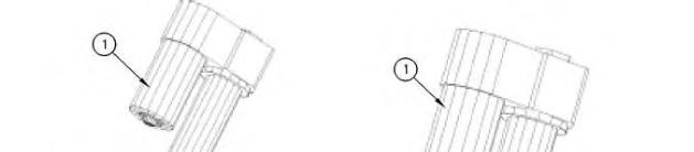
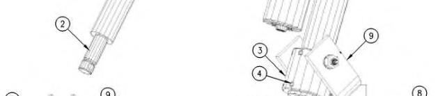
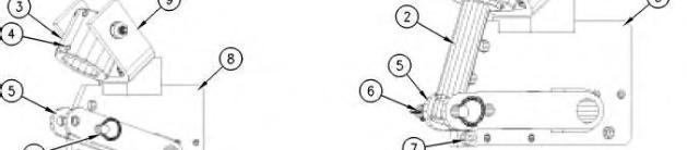
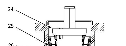
Illustration 5
(1) Actuator
(2) Actuatorrod
(3) Actuatorcollar
(4) Setscrew
(5) Operator fork
(6) Hitch pin
(7) Mechanicalstop
(8) Alignment plate (9) Actuatorclevis
a. Remove hitch pin (6).
b. Position operator fork (5) against mechanical stop (7).
c. Manually turn actuator rod (2) outward until the rod isfully extended. When the rod reaches the end of travel, the actuator motor can be felt turning.
d. Retract actuator rod (2) by rotating actuator rod (2) by 180 degrees. The actuator motor should not turn.
e. Slide actuator (1) through actuator collar (3). Verify that the actuator collar is oriented so that setscrews(4) are facing away from actuator clevis(10).
f. Retracting actuator rod (2) by 1/4 turn may be required in order to line up the hole in actuator rod (2) with the hole in operator fork (5).
g. Insert hitch pin (6) through operator fork (5) and actuator rod (2).
h. Verify that operator fork (5) is against mechanical stop (7). Make sure that the actuator motor is oriented in the correct position. The actuator motor must be clear of obstructions. Rotate the actuator in the collar prior to tightening setscrews (4).
i. Apply 9S-3263 Thread Lock Compound to setscrews(4) and install the setscrews. Tighten the setscrew to a torque of 16.3 N·m (12.0 lb ft).
Note: Do not tighten setscrews more than 1.5 threads below the surface.
9. Connect the end of the cable for the actuator to the plug end of the extension cable.
Installation of Blaze Blocker
This feature is integral to the control box. The required connector is part of the harness from the control box. The connector will receive the signal from the fire suppression system.
Note: Before the circuit istested, be sure that the canistersfor the fire suppression system are disconnected in order to prevent the canisters from discharging when the circuit is energized. Reconnect the canisters after the test of the circuit is complete.
1. Locate the control box.
2. Determine whether the fire suppression system is manual or automatic.
3. Followthe appropriate procedure:
a. Manual Fire Suppression System
Install a switch that is normally open near the fire suppression plunger.
Connect a 16 gauge wire from the common terminal of the switch to ground.
Connect a 16 gauge wire from the other pole of the switch into pin 1 of a deutsche connector. The length of the signal wire will depend on the distance from the switch to the connector on the control box. Pin 2 of the deutsche connector isleft empty.
Connect the plug from the switch to the receptacle on the controller.
Apply power to the control box and turn the switch ON. The control box will place the fan into the NEUTRAL position. The "PUSH" light and the "PULL" light on the remote display will be flashing as well asthe T1 light and T2 light inside the control box. This indicates that the switch is wired properly and that blaze blocker is on.
Move the switch to the OFF position in order to resume normal operation.
When a fire is observed, the operator should flip the switch first. Then, the operator should activate the fire suppression system.
b. Automatic Fire Suppression System
Locate the warning alarm relay circuit. Thiscircuit will activate a warning relay on the fire suppression system. This indicatesthat a fire hasbeen detected.
Connect a 16 gauge wire from the common terminal of the relay to ground.
Connect a 16 gauge wire from the other pole of the relay into pin 1 of a deutsche connector. The length of the signal wire will depend on the distance from the switch to the connector on the control box. Pin 2 of the deutsche connector isleft empty.
Connect the plug from the relay to the receptacle on the controller.
When the relay is energized, the control box will place the fan into the NEUTRAL position. The "PUSH" light and the "PULL" light on the remote display will be flashing as well as the T1 light and T2 light inside the control box. This indicates that the switch is wired properly and that blaze blocker is on.
Product: TRACK LOADER
Model: 963C TRACK LOADER BBD
Configuration: 963C TRACK-TYPE LOADER TIER II BBD00001-UP (MACHINE) POWERED BY 3126B Engine
Disassembly and Assembly
Flexxaire Fan
Media Number -RENR3699-07 Publication Date -01/02/2012 Date Updated -21/06/2016
Hydraulic Actuated Fan - Assemble
SMCS - 1356-016-HR
Preliminary Fan Assembly
i06636599
Note: Refer to the Service Manual Disassembly and Assembly (Engine Supplement), "Reversible FanAssemble" for the Track Feller Buncher machinesonly on the assembly procedure.
Note: Before you proceed, ensure that you know the correct model of the hydraulic actuated fan. Refer to Operation and Maintenance Manual, "Model View Illustrations" to identify the model of the fan.
1. Clean all surfaces and threads prior to assembly.
2. Make sure that all the parts are present for the assembly.
3. To ease assembly, lubricate all the seals and the O-rings as you assemble the fan.
Note: Unless the instructions state otherwise, do NOT apply Loctite or any equivalent adhesives to any of the fasteners that contact aluminum parts.
Main Shaft - Assemble
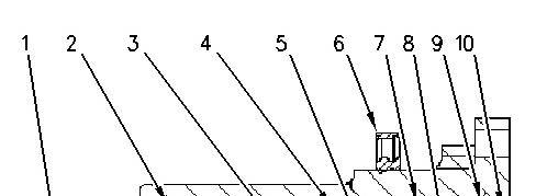
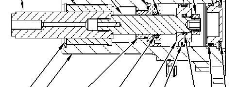
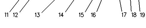
Illustration 1 g00906033
(1) Hexthrough shaft
(2) Bushing
(3) Rodshaft
(4) O-ring
(5) Backup ring
(6) Seal
(7) External Seal
(8) Hexnut
(9) Backup ring
(10) End cap
(11) Bushing snap ring
(12) Main shaft
(13) Seal Retainer
(14) Internal Seal
(15) Piston
(16) Backup rings
(17) O-ring
(18) O-ring
(19) Snapring
For reference, Illustration 1 picturesa crosssection view of the main shaft that iscompletely assembled.
1. Position the main shaft in a vise.
Note: If an extension is used on the main shaft, apply a few dropsof 4C-9506 Retaining Compound to the threads of the extension. Thread the extension and tighten the extension to a torque of 34 N·m (25 lb ft).
2. Clean the inside of the main shaft and seal retainer of all possible debris with 138-8441 Brake Cleaner.
2 g00906204
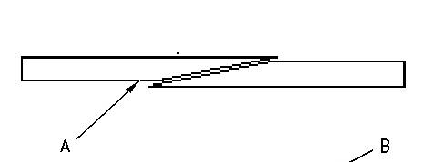
3 g00906209
(A) The correct positionfor the backuprings (B) The incorrect positionfor the backup rings
3. Place internal seal (14) into the seal retainer (13).
4. Insert both backup rings (5) on either side of the internal seal (13).
Note: Make sure that the endsof the backup rings are enclosed on each other properly. See Illustration 3 for the correct positioning of the ends of the backup rings.
5. Apply a small amount of grease on O-ring (4) to hold the O-ring in place. Place O-ring (4) in the Oring groove of seal retainer (13).
6. Apply a thin coating of oil onto the inside of the internal seal.
7. Thread seal retainer (13) into the rear of main shaft (12).
Note: Do NOT apply Loctite or equivalent adhesives to the threads of the seal retainer.
8. Use Snap-On S6183 Socket to tighten the seal retainer to a torque of (13) to 34 N·m (25 lb ft).
9. Slide rod shaft (3) through seal retainer (13) until the end of the hex through shaft (1) comesto rest against seal retainer (13). Repeat thisstep for the various sides of the hex through shaft until you find a position that givesno resistance except for the resistance from the seal.
Note: Use a finger on the other side of the main shaft to help guide the rod shaft past the seal retainer.
Note: When you are sliding the rod shaft past seal retainer (13), be careful not to damage the internal seal and/or the backup rings.

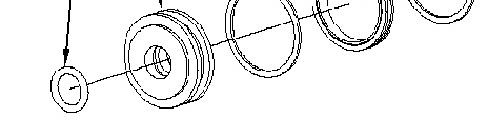
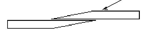
Illustration 4
10. Place external seal (7) onto piston (15).
11. Insert both backup rings (16) on either side of external seal (7).
Note: Make sure that the endsof the backup rings are enclosed on each other properly. See Illustration 3 for the correct positioning of the ends of the backup rings.
12. Place internal O-ring (17) into the groove on piston (15).
13. Apply a thin coating of oil onto external seal (7) and onto O-ring (17) of the piston.
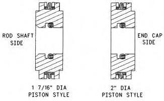
Illustration 5
g00906300
14. Push piston (15) into the rear of main shaft (12) and onto the end of rod shaft (3) until the piston rests against the shoulder of the rod shaft.
Note: Some designs have a spacer that needs to be installed. The spacer is located between seal retainer (13) and the piston (15).
Note: The orientation of the piston prior to installation is critical. There are two different styles of piston that are used. See Illustration 5 for the proper orientation.
Note: Be careful when you slide piston (15) into main shaft (12) and onto the end of rod shaft (3). Do not damage external seal (7), backup rings (16), or O-ring (17).
15. Apply 9S-3263 Thread Lock Compound to the threads of hex nut (8).
16. Thread hex nut (8) onto rod shaft (3) and tighten the hex nut to a torque of 34 N·m (25 lb ft).
Note: Slide the shafts and the piston in and out to make sure that the resistance isslight.
17. Push piston (15) until the piston comes to rest against seal retainer (13).
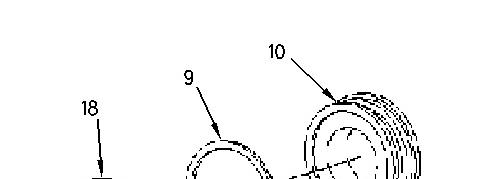

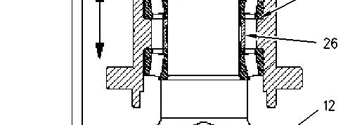
Illustration 6 g00906341
18. Install backup ring (9) onto end cap (10).
Note: Make sure that the endsof the backup rings are enclosed on each other properly. See Illustration 3 for the correct positioning of the ends of the backup rings.
19. Install O-ring (18) onto end cap (10).
20. Lubricate the O-ring with a thin coating of oil.
21. Insert end cap (10) into the rear of main shaft (12).
22. Insert rear snap ring (19) into main shaft (12) to secure end cap (10). Be sure that snap ring (19) is properly seated in the main shaft.
Note: The square edge on the snap ring must be facing outward and the edge must be properly seated. If an extension to the main shaft is used in the assembly, install the snap ring into the main shaft extension.
23. Remove the main shaft from the vise.
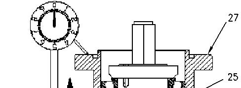
Mounting Main Shaft onto Mounting Bracket

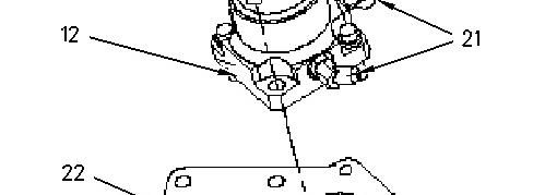

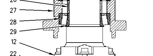
Illustration 7 g00906423
1. Thread hydraulic connectors (21) onto main shaft (12) by hand to correctly orient the connectors.
Note: If information on the orientation of the connectorsisrequired, contact Flexxaire at (780) 9306832.
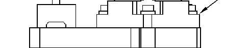
2. Mount the fan mounting bracket into a horizontal position, onto a vertical mounting stand, or onto a vise.
3. Place main shaft (12) onto fan mounting bracket (22).
Note: The proper orientation of the main shaft onto the fan mounting bracket must be kept when you assemble these partstogether. This will keep the centerline of the fan assembly and the height of the engine mounting correct, and the hydraulic lines will connect correctly.
4. Apply 9S-3263 Thread Lock Compound onto the threads of fastener (20).
5. Install fastener (20) into fan mounting bracket (22) and tighten to the specification.
6. Secure hydraulic connectors(21) to main shaft (12), but do NOT tighten the connectors excessively.
7. If necessary, install the hydraulic hoses on the fan.