

Product: TRACK LOADER
Model: 953C TRACK LOADER BBX
Configuration: 953C TRACK-TYPE LOADER BBX00001-UP (MACHINE) POWERED BY 3126B Engine
Disassembly and Assembly
Flexxaire Fan
Media Number -RENR3699-07
Publication Date -01/02/2012 Date Updated-21/06/2016
Control System - Remove and Install
SMCS - 1356-010-YC
General Installation
Installation of the Mark I Control System
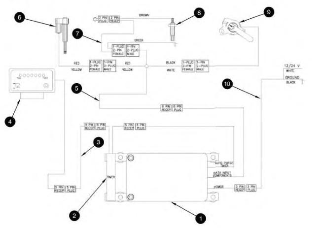
Illustration 1 g00564778
Mark I Control System
(1) Mark I control box (2) AUTO-purge timer (3) Cable for remote display (4) Remote display (5) Pigtail
i01739978
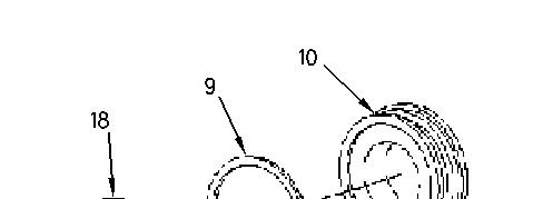
(6) Actuator
(7) Temperature andgroundcable
(8) Temperature sensor
(9) Position sensor
(10) Power cable
1. Mount control box (1) in the operator's compartment. The mounting location should meet the following criteria:
Minimal debris and vibration
Safe from water thatis high pressure
Accessible for future adjustments or changes in setup
The control box should be mounted in a vertical position, and vibration mounts that are supplied with the controller shouldbe installed.
2. AUTO-purge timer (2) is locatednear control box (1). Connect the end of the cable for AUTO-purge timer (2) to the plug end of the cable for the AUTO-purge timer on control box (1).
3. Cable for remote display (3) may not be required for all installations. Connect the end of the cable for remote display (3) to the plug end of AUTO-purge timer (2). Connect the plug end of cable for remote display (3) into the end of the pigtail for remote display (4).
4. Mount remote display (4) onthe dash or another convenientlocation. The remote display should be visible andaccessible to the operator. Connect the end of the cable for remote display (4) to the plugend of the cable for remote display (3).
5. Connect the end of pigtail (5) tothe plug end of the cable for control box (1). Pigtail(5) splits into a harness with three connectors. One endgoes to actuator (6). One end goes to temperature sensor (8). One endgoes to position sensor (9).
6. The following steps are for installation of actuator (6):
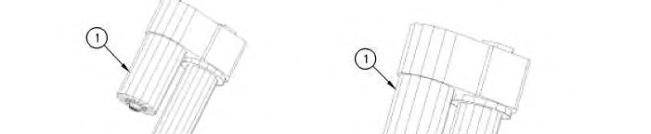
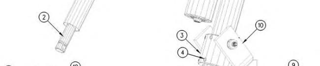
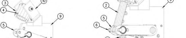
Illustration2 g00592444
(1) Actuator
(2) Actuator rod
(3) Actuator collar
(4) Setscrew
(5) Operator fork
(6) Hitch pin
(7) Mechanical stop (8) Position sensor (9) Alignment plate (10) Actuator clevis
a. Remove hitch pin (6).
b. Position operator fork (5) against mechanical stop (7).
c. Manually turn actuator rod (2) outward until the rod is fully extended. When the rod reaches the end of travel, the actuator motor canbe felt turning.
d. Retract actuator rod(2) by the rotating actuator rodby180 degrees. The actuator motor should not turn.
e. Slide actuator (1) through actuator collar (3). Verify that the actuator collar is orientedsothat setscrews (4) are facing away from actuator clevis (10).
f. Retracting actuator rod (2) by 1/4 turn may be requiredin order toline up the hole inactuator rod (2) with the hole in operator fork (5).
g. Insert hitch pin (6) through operator fork (5) andactuator rod (2).
h. Verify that operator fork(5) is against mechanical stop (7). Make sure thatthe actuator motor is oriented in the correctposition. The actuator motor must be clear of obstructions. Rotate the actuator in the collar prior to tightening setscrews (4).
i. Apply 9S-3263 Thread Lock Compound to setscrews (4) and install the setscrews. Tightenthe setscrew to a torque of 16 N·m (12 lb ft).
Note: Do not tighten setscrews more than 1.5 threads below the surface.
j. Connect the endof the cable for the actuator to the red and yellow plug of pigtail (5).
7. Connect the end of temperature and ground cable (7) to the plug with greenand blackwires of pigtail (5). The ground wire (green) is secured with a bolt that threads in to the support arm of the fan assembly. The brown lead wire is connected tothe top of temperature sensor (8).
8. Thread temperature sensor (8) intothe engine block. An area that is close to the water temperature regulator is recommended. Temperature sensor (8) comes withthree thread adapters. The brown lead wire of temperature and ground cable (7) connects to the top of temperature sensor (8).

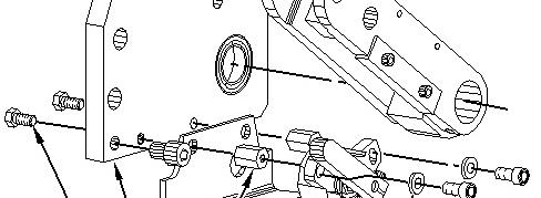
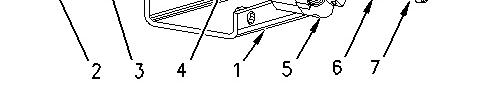
Illustration3
(1) Mounting bracketfor the position sensor (2) Bolt (3) Alignmentplate (4) Mounting nut for the positionsensor (5) Position sensor (6) Washer (7) Capscrew
9. The following steps are for installation of position sensor (9):
g00918804
a. Place mounting bracket(1) for the position sensor against alignment plate (3).
b. Thread bolt (2) into mounting nut (4) for the position sensor through alignment plate (3) andposition sensor mounting bracket (1). Tighten bolt (2) to a torque of 16.3 N·m (12.0 lb ft).
c. Place positionsensor (5) in the correct location.
d. Put washer (6) on capscrew (7). Threadcapscrew (7) into mounting nut (4) for the position sensor through position sensor (5).
e. Connect the plug end of the cable for position sensor (5) to the end of the pigtail.
10. Connect the plug endof power cable (10) to the end of the power cable for the control box.
White wire - This wire connects to a 10 Amp fuse or to a circuit breaker. The power source that is being used must allow power to the control box when the engine is not running.
Black wire - This wire connects to the main disconnect or a different ground location.
Installation of the Mark IIIControl System
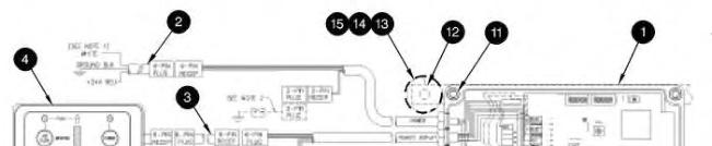
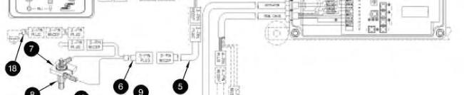
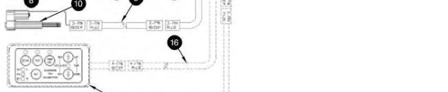

Illustration 4
Mark III controlsystem
(1) Mark III control box
(2) Power cable
(3) Extension cable for remote display
(4) Remote display
(5) Extension cable for temperature sensor
(6) Cable for temperature sensor
(7) Ground collar
(8) Temperature sensor
(9) Extension cable for actuator
(10) Actuator
(11) Screw
(12) Mounting bracket
(13) Vibration mount
(14) Washer
g00573394
This is the sample of the manual
Click on the download link for complete Manual
(15) Nut (16) Cable for remote calibrator (17) Remote calibrator (18) Pressure switch
1. Mount control box (1) in the operator's compartment. The mounting location should meet the following criteria:
Minimal debris and vibration
An area that is away from high pressure washes
Accessible for future adjustments and changes in setup
The control box should be mounted in a vertical position and the vibration mounts that are supplied with the control box should be installed.
2. Install temperature sensor (8) with the NPT bushing that is supplied. The sensor should be installed in the water jacket of the engine. The most preferable location for the temperature sensor is near the coolant temperature regulator. This will allow the sensor tosense maximum water temperature.
3. Route extension cable for temperature sensor (5) from the control box to the temperature sensor. Connect cable for temperature sensor (6) toextension cable (5). Connect the black wire to the groundcollar. Install the groundcollar around the hex portion of the temperature sensor and tighten the clamping screw. Connect the white wire to the top of the temperature sensor.
4. Route extension cable for actuator (9) from the control box to the actuator.
5. Connect power cable (2).
Red wire - This wire connects to a 10 Amp fuse or to a circuit breaker. The connection should be made to a circuit that is isolated during operation of the starter. This circuit should not be powered when the ignition keyis in the OFF position.
Black wire - This wire connects to the main disconnect or a stable ground location.
6. Mount remote display (4) onthe dash or another convenientlocation. The remote display should be visible andaccessible to the operator. Connect the remote display to the control box with an extensioncable for remote display (3). If it is notpractical to mount the remote display in the operator's compartment, the display should be mounted inan enclosed area that will not be exposed to the elements. The display is not required for operation of the control box.
7. Applications that use the radiator fan to coolthe A/C condenser core should use pressure switch (18). The pressure switch should be installed on the high pressure side of the compressor. Remove the jumper wire from cable for temperature sensor (6) and plugin pressure switch(18). When the condenser core reaches a set pressure, the fan is put into full pitch in order tocool the condenser core.
8. The following steps are for installation of actuator (10):
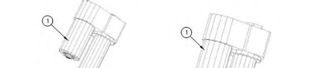
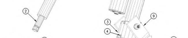
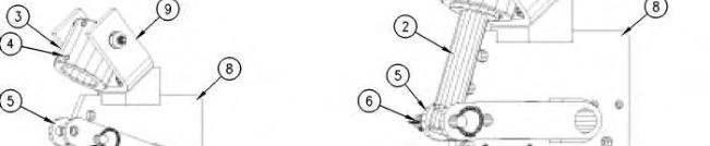
Illustration5 g00592173
(1) Actuator
(2) Actuator rod
(3) Actuator collar
(4) Setscrew
(5) Operator fork
(6) Hitch pin
(7) Mechanical stop
(8) Alignment plate
(9) Actuator clevis
a. Remove hitch pin (6).
b. Position operator fork (5) against mechanical stop (7).
c. Manually turn actuator rod (2) outward until the rod is fully extended. When the rod reaches the end of travel, the actuator motor canbe felt turning.
d. Retract actuator rod(2) by rotating actuator rod (2) by 180 degrees. The actuator motor should not turn.
e. Slide actuator (1) through actuator collar (3). Verify that the actuator collar is orientedsothat setscrews (4) are facing away from actuator clevis (10).
f. Retracting actuator rod (2) by 1/4 turn may be requiredin order toline up the hole inactuator rod (2) with the hole in operator fork (5).
g. Insert hitch pin (6) through operator fork (5) andactuator rod (2).
h. Verify that operator fork(5) is against mechanical stop (7). Make sure thatthe actuator motor is oriented in the correctposition. The actuator motor must be clear of obstructions. Rotate the actuator in the collar prior to tightening setscrews (4).
i. Apply 9S-3263 Thread Lock Compound to setscrews (4) and install the setscrews. Tightenthe setscrew to a torque of 16.3 N·m (12.0 lb ft).
Note: Do not tighten setscrews more than 1.5 threads below the surface.
9. Connect the end of the cable for the actuator to the plug end of the extension cable.
Installation of Blaze Blocker
This feature is integral to the control box. The required connector is part of the harness from the control box. The connector will receive the signal from the fire suppression system.
Note: Before the circuit is tested, be sure that the canisters for the fire suppression system are disconnected in order to prevent the canisters from discharging when the circuit is energized. Reconnect the canisters after the test of the circuit is complete.
1. Locate the control box.
2. Determine whether the fire suppression system is manual or automatic.
3. Follow the appropriate procedure:
a. Manual Fire SuppressionSystem
Install a switch that is normally open near the fire suppression plunger.
Connect a 16 gauge wire from the common terminal of the switch toground.
Connect a 16 gauge wire from the other pole of the switch into pin 1of a deutsche connector. The length of the signal wire will depend on the distance from the switch to the connector on the control box. Pin 2 of the deutsche connector is left empty.
Connect the plug from the switch to the receptacle on the controller.
Apply power to the control box and turn the switch ON. The control box will place the fan into the NEUTRAL position. The "PUSH" light and the "PULL" light on the remote display will be flashing as well as the T1 light andT2 light inside the control box. This indicates thatthe switch is wired properly andthat blaze blocker is on.
Move the switch to the OFF position in order toresume normal operation.
When a fire is observed, the operator should flip the switch first. Then, the operator should activate the fire suppressionsystem.
b. Automatic Fire Suppression System
Locate the warning alarm relay circuit. This circuit will activate a warning relay on the fire suppression system. This indicates that a fire has beendetected.
Connect a 16 gauge wire from the common terminal of the relay to ground.
Connect a 16 gauge wire from the other pole of the relayinto pin 1 of a deutsche connector. The length of the signal wire will depend on the distance from the switch to the connector on the control box. Pin 2 of the deutsche connector is left empty.
Connect the plug from the relay tothe receptacle on the controller.
When the relayis energized, the control box will place the fan into the NEUTRAL position. The "PUSH" light and the "PULL" light onthe remote display will be flashing as well as the T1 light and T2 light inside the control box. This indicates that the switch is wired properly and that blaze blocker is on.

Product: TRACK LOADER
Model: 953C TRACK LOADER BBX
Configuration: 953C TRACK-TYPE LOADER BBX00001-UP (MACHINE) POWERED BY 3126B Engine
Disassembly and Assembly
Flexxaire Fan
Media Number -RENR3699-07
Hydraulic Actuated Fan - Assemble
SMCS - 1356-016-HR
Preliminary Fan Assembly
Note: Refer tothe Service Manual Disassembly and Assembly (Engine Supplement), "Reversible Fan- Assemble" for the TrackFeller Buncher machines onlyon the assembly procedure.
Note: Before you proceed, ensure that you knowthe correct model of the hydraulic actuated fan. Referto OperationandMaintenance Manual, "Model View Illustrations" to identify the model of the fan.
1. Clean all surfacesand threadsprior to assembly.
2. Make sure that all the parts are present for the assembly.
3. To ease assembly, lubricate all the seals andthe O-rings asyou assemble the fan.
Note: Unless the instructions state otherwise, do NOT apply Loctite or any equivalent adhesivesto any of the fasteners that contact aluminum parts.
Main Shaft - Assemble
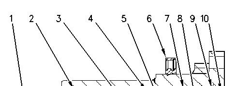
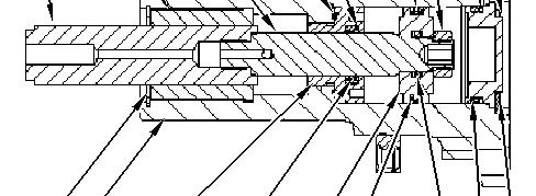
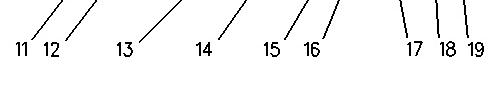
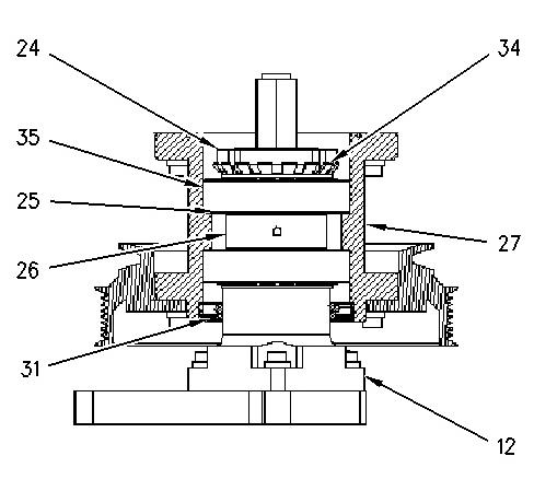
Illustration1 g00906033
(1)Hexthroughshaft
(2)Bushing
(3)Rodshaft
(4)O-ring
(5)Backup ring
(6)Seal
(7)External Seal
(8)Hexnut
(9)Backup ring
(10)End cap
(11)Bushingsnapring
(12)Mainshaft
(13)Seal Retainer
(14)Internal Seal
(15)Piston
(16)Backup rings
(17)O-ring
(18)O-ring
(19)Snapring
For reference, Illustration 1 pictures a cross section viewof the main shaft that iscompletely assembled.
1. Position the main shaft in a vise.
Note: If an extension is used on the main shaft,applya fewdropsof 4C-9506 Retaining Compound to the threadsof the extension. Threadthe extension and tighten the extension to a torque of34 N·m (25 lbft).
2. Clean the inside of the main shaft and seal retainer ofall possible debriswith 138-8441 Brake Cleaner.
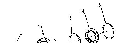
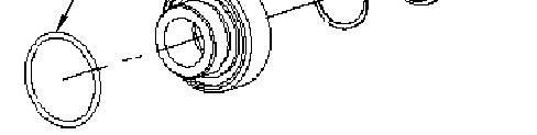
Illustration2 g00906204
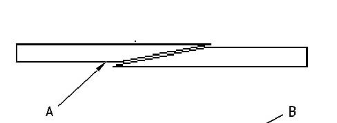
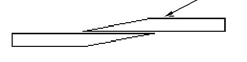
Illustration3 g00906209
(A) The correct positionforthe backuprings (B)The incorrect positionforthe backup rings
3. Place internal seal (14) into the seal retainer(13).
4. Insert bothbackup rings (5) on either side of the internal seal (13).
Note: Make sure that the ends ofthe backup rings are enclosedon each other properly.See Illustration 3 for the correct positioningof the endsof the backup rings.
5. Apply a small amount of grease on O-ring (4) to hold the O-ring in place. Place O-ring (4) in the O-ringgroove of seal retainer (13).
6. Apply a thincoating of oil onto the inside of the internal seal.
7. Thread seal retainer (13) into the rear of main shaft (12).
Note: DoNOT apply Loctite or equivalent adhesivesto the threadsof the seal retainer.
8. Use Snap-On S6183 Socket to tightenthe seal retainer to a torque of (13) to 34 N·m (25 lb ft).
9. Slide rodshaft (3) throughseal retainer (13) until the end ofthe hex through shaft (1) comes to rest against seal retainer (13). Repeat this step for the varioussides of the hex throughshaft until you find a position that givesno resistance except for the resistance from the seal.
Note: Use a finger on the other side of the main shaft to help guide the rod shaft past the seal retainer.
Note: When you are sliding the rod shaft past seal retainer (13), be careful not to damage the internal seal and/or the backup rings.
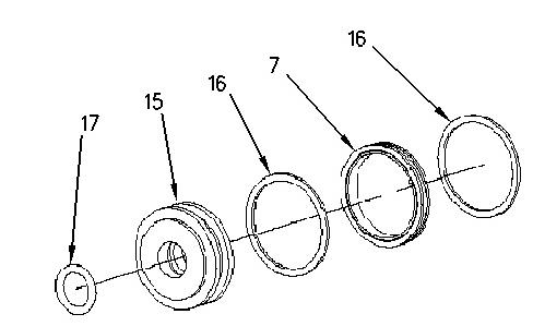
Illustration4
10. Place external seal (7) onto piston(15).
11. Insert bothbackup rings (16) on either side of external seal (7).
g00906297
Note: Make sure that the ends ofthe backup rings are enclosedon each other properly.See Illustration 3 for the correct positioningof the endsof the backup rings.
12. Place internal O-ring (17) into the groove on piston(15).
13. Apply a thincoating of oil onto external seal (7) and ontoO-ring (17) of the piston.
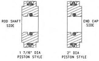
Illustration5
14. Push piston (15) into the rear of main shaft (12) and onto the end of rodshaft (3) until the pistonrests against the shoulder of the rod shaft.
Note: Some designshave a spacer that needs to be installed.The spacer islocated between seal retainer (13)and the piston (15).
Note: The orientation of the piston prior to installation is critical. There are two different stylesof piston that are used. See Illustration 5for the proper orientation.
Note: Be careful when you slide piston (15) into main shaft (12) and onto the end of rodshaft (3). Do not damage external seal (7), backup rings(16), or O-ring (17).
15. Apply 9S-3263 Thread Lock Compoundto the threads ofhexnut (8).
16. Thread hex nut (8) ontorod shaft (3)andtighten the hex nut to a torque of 34 N·m (25 lb ft).
Note: Slide the shafts and the piston in and out to make sure that the resistance is slight.
17. Push piston (15) until the piston comestorest against seal retainer (13). Illustration6

18. Install backup ring (9) ontoend cap (10).
Note: Make sure that the ends ofthe backup rings are enclosedon each other properly.See Illustration 3 for the correct positioningof the endsof the backup rings.
19. Install O-ring(18) onto end cap (10).
20. Lubricate the O-ringwith a thin coating of oil.
21. Insert endcap (10) intothe rear of main shaft (12).
22. Insert rear snap ring (19) into main shaft (12) to secure end cap (10). Be sure that snap ring (19) isproperly seated in the main shaft.
Note: The square edge on the snap ringmust be facing outward and the edge must be properly seated. If an extension to the main shaft isused in the assembly, install the snap ring intothe main shaft extension.
23. Remove the main shaft from the vise.
Mounting Main Shaft onto Mounting Bracket

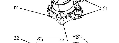

Illustration7 g00906423
1. Thread hydraulic connectors(21) onto main shaft (12) by hand to correctly orient the connectors.
Note: If informationon the orientation of the connectors is required, contact Flexxaire at (780) 930-6832.
2. Mount the fanmountingbracket into a horizontal position, ontoa vertical mounting stand, or onto a vise.
3. Place main shaft (12) onto fan mounting bracket (22).
Note: The proper orientation of the mainshaft onto the fan mounting bracket must be kept when you assemble these parts together. This will keep the centerline of the fan assembly and the height of the engine mounting correct, and the hydraulic lines will connect correctly.
4. Apply 9S-3263 Thread Lock Compoundonto the threadsof fastener (20).
5. Install fastener (20) into fan mounting bracket (22) and tighten to the specification.
6. Secure hydraulic connectors (21)to main shaft (12), but do NOT tighten the connectors excessively.
7. If necessary, install the hydraulic hoses on the fan.
Main Shaft - Pressure Check
Performing a pressure checkon the main shaft will ensure that all the seals are properly seated. If you do not perform a pressure check, several problems can arise. Such problemsinclude leaking hydraulic fluid and inadequate hydraulic pressure that isneeded to change the pitch ofthe blades.
1. Connect a hydraulic source with a shutoff valve and a hydraulic pressure gauge betweenthe pressure source andthe fan. Repeat thisstep on both lines. Ensure that the shutoff valve is in between the pressure source and the gauge.
Note: If a hydraulic source is not available, a source of air can be used.
2. Pressurize the main shaft to a pressure that is equal to the normal operating pressure, and close the first shutoff valve. Repeat thisstep on the other line also.
3. Leave pressure to the mainshaft for a minimum of15 minutes.
4. Check forleaks around the main shaft.
5. If no leaks are detected, release the hydraulic pressure and remove the shutoff valve and the hydraulic pressure gauge from both of the lines.
Note: If leaks are found during the pressure check of the main shaft, the main shaft must be disassembledandassembled again to rectifythe problem.
6. Leave the hydraulic source connected tothe hydraulic fittingstoperform the “Bearing Carrier - Preassemble”.
Bearing Carrier - Preassemble
1. During the assembly of the Pre-Bearing Carrier, mainshaft (12) must remain mounted in the vertical position. Refer to Illustration8.
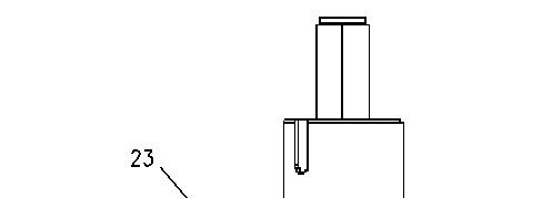
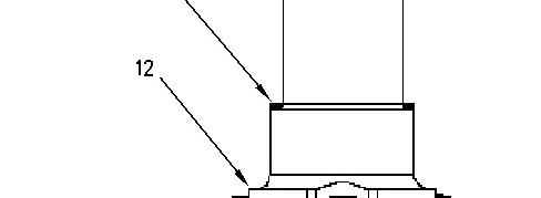
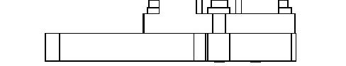
Illustration8 g00906491
2. Place internal fillet spacer (23) ontomain shaft (12).
Note: Not all assemblieswill require an internal fillet spacer. Ifnecessary, the beveled edge must match the edge ofthe radiuson the main shaft. Refer to Illustration 9.
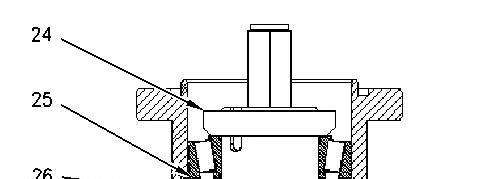
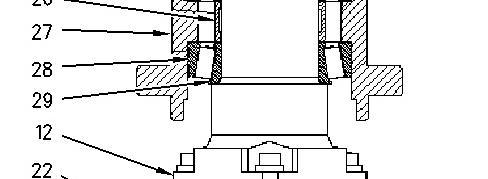

Illustration9 g00906493
3. Push cups(28) into bearing carrier (27).
4. Slide first bearing cone (29) ontomain shaft (12).
5. Slide bearing spacer (26) ontomain shaft (12).
6. Slide shims (25) onto main shaft (12).
Note: Measure thicknessof the old shims and replace the old shimswith newshims whichare supplied in a bearing kit.
7. Set bearing carrier (27) onto the first bearing set that is onthe main shaft.
8. Place the second bearing cone into the bearing carrier.
9. Thread locknut (24) onto the mainshaft and tighten the locknut with a certified torque wrench to the specific value.
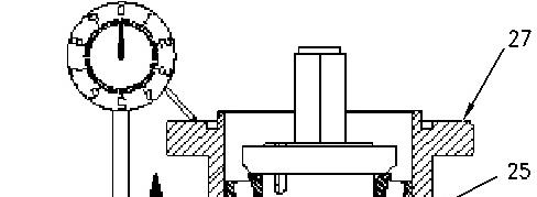
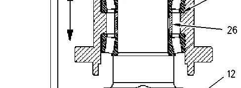
Illustration10 g00906504
10. Mount a dial indicator that has a magnetic base onto a stable base suchasthe fanmounting bracket.
11. Use the indicator to measure the vertical movement of bearing carrier (27) on the main shaft (12).
12. Raise and lowerthe bearing carrier to measure the vertical movement. Perform thisstep without any load.
Note: The vertical movement of the bearingcarrier must be between the specified values. Refer to Table 1for clearances.
Table 1
Bearing Clearances
(1) Theshims comein thicknesses of0.002, 0.003, 0.005, and 0.010inches. The maximum stack height of the shims should notexceed0.8890 mm (0.035inch). The maximum number of shims is 5.
13. Add and remove shims(25) to ensure that the vertical movement iswithin the specifications.
14. Remove the dial indicatorfrom the assembly.
15. Remove locknut (24) from main shaft (12).
Note: While youremove the components, stack the components in the same order. This will ease assembly later.
16. Lift off bearing carrier (27) and place the bearingcarrier to the side. Place the top bearing on top ofthe locknut.
17. Remove shims(25), bearing spacer (26), and the lower bearing cone from main shaft (12).
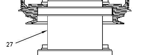
Bearing Carrier - Assemble
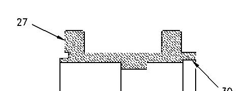
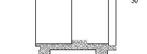

Illustration11 g00906544
1. Clean the seal bore (30) of bearing carrier (27) with 138-8441 Brake Cleanerto remove any adhesivesor debris.
2. Place bearingcarrier (27) horizontally.
3. Apply 4C-9507 Retaining Compound and 169-5464 Quick Cure Primer to seal bore (30) of bearing carrier (27). Also, apply thisadhesive to the bore surface of the seal. Coat the surfaces completely.
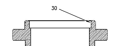
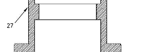

Illustration12 g00906549
4. Place bearingcarrier (27) vertically so that the seal bore (30) is directed upward.
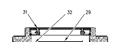
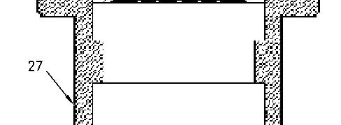

Illustration13 g00906552
5. Place first mainbearing cone (29)into the cup (32) of bearing carrier (27).
6. Press seal (31) into the seal bore until the face of the seal is flush with the edge of bearing carrier(27).
Note: The seal must be square with the seal bore of the bearingcarrier to ensure the proper seal.
7. Flip bearing carrier(27) sothat the seal bore isfacingdownward on the work surface.
Note: If the fan assembly contains a spool,proceed to "Main Shaft and Bearing Carrier Assembly forFans withSpools". If the fan assembly does not contain a spool proceed directly to "MainShaft and Bearing CarrierAssemblyfor Fanswithout Spools".
Main Shaft and Bearing CarrierAssembly for Fans with Spools
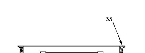

14 g00906559
1. Install pulley(33) onto bearing carrier (27).
2. Lubricate seal (31) withlight oil.
3. Install bearing carrier assembly (27) onto mainshaft (12).
Note: When you slide seal (31) overthe shoulder of mainshaft (12), take care not to damage the seal. Also, make sure that no part ofthe lip of the seal isturned upward.
4. Install the spacerfor the bearing carrier (27) and shims (25)onto main shaft (12).
Note: When you install shims, place the smaller thicknesses first. Turnburrs upward onthe main shaft.
5. Slide secondbearing set (35) and lockwasher (34) onto mainshaft (12).
6. Apply 4C-9506 Retaining Compound to the threads on the mainshaft. Threadlocknut (24) onto main shaft (12). Tighten the locknut tothe correct specification.
Note: The beveled edge of the locknut must face toward the lockwasher. Align one of the slotson the locknut withone of the tabs on the lockwasher. When you align the tab and the slot, alwaystighten the locknut. Never loosen the locknut whenyou are aligning the taband the slot.
7. Bend the lockwasher tab ontothe slot ofthe locknut.
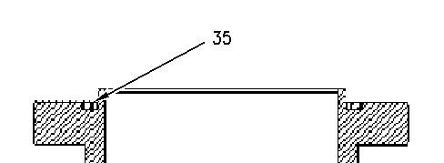
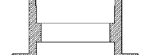

Illustration16 g00906570
8. Clean the O-ring groove and install O-ring (35) onthe carrier.
Note: ApplySteps 9 through 16 only if the flange and/orthe oil dam were removed from the spool.
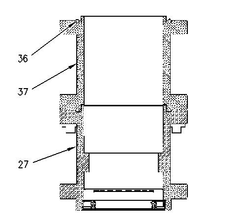
Illustration17 g00916982
9. Clean the O-ring groove on the spool and place O-ring (36) intothe groove on spool (37).
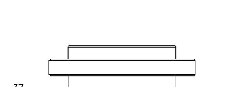
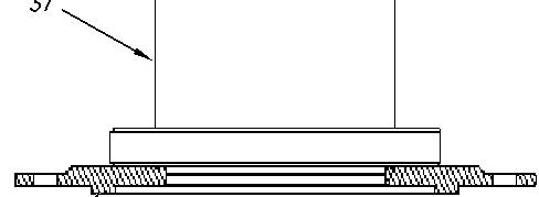
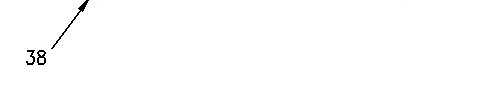
Illustration18 g00906578
10. Clean the face of flange (38) with138-8441Brake Cleaner. Place flange (38) onto spool (37) and align the holes.
Note: In some assemblies,the bearing carrier contains an alignment screwwhich must be used toalign the flange.
11. Hold the flange and the spool together, and flip over the combination. Do not dislodge the Oring.
12. Apply 9S-3263 Thread Lock Compoundto the last 9.52 mm (0.375 inch) of the fasteners.
Note: This step is not applicable to FX 2000Fans.
This is the sample of the manual
Click on the download link for complete Manual

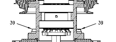

Illustration19 g00917072
13. Insert fasteners(39) and tighten tothe correct value.