

Product: TRACK LOADER
Model: 953B TRACK LOADER 5MK
Configuration: 953B TRACK-TYPE LOADER 5MK00001-UP (MACHINE) POWERED BY 3116 ENGINE
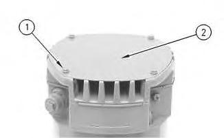
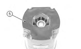
Disassembly and Assembly 26SI Series Alternator
Media Number -RENR1252-01
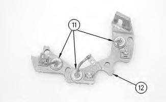
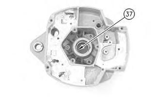
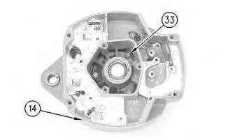
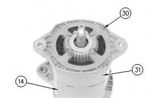
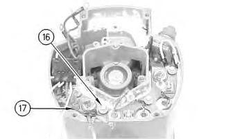
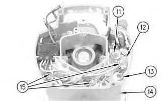
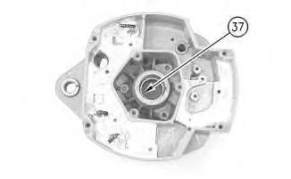
Alternator - Assemble
Assembly Procedure
Note:
i01167078

Note:
Note:
This is the sample of the manual
Click on the download link for complete Manual


Note:

Product: TRACK LOADER
Model: 953B TRACK LOADER 5MK
Configuration: 953B TRACK-TYPE LOADER 5MK00001-UP (MACHINE) POWERED BY 3116 ENGINE
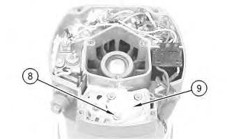
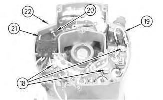
Disassembly and Assembly 26SI Series Alternator
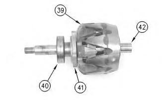
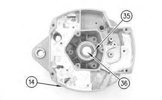
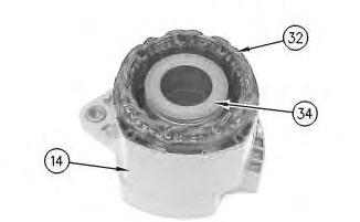
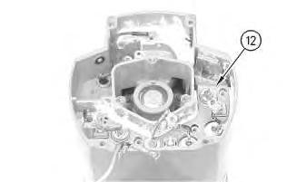
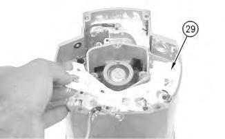
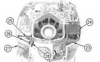
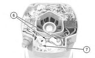
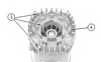
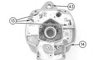
Alternator - Disassemble
Disassembly Procedure
Start By:


Note:
Note:
Note:

Product: TRACK LOADER
Model: 953B TRACK LOADER 5MK
Configuration: 953B TRACK-TYPE LOADER 5MK00001-UP (MACHINE) POWERED BY 3116 ENGINE
Disassembly and Assembly
Comfort Series Seat For Caterpillar Machines Media
i01723170
Air Suspension With Air Valve Knob Height
Adjustment
Assemble
SMCS - 7324-016-AJ
Assembly Procedure
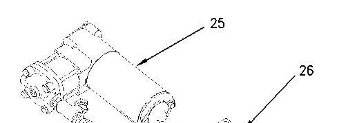

Illustration 1 g00891451
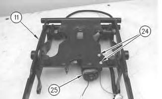
1. Install compressor assembly (25) to mount (26). Make sure that compressor assembly (25) is seated firmly in mount (26) .
2
2. Install bolts (24) in order to attach compressor assembly (25) to scissor assembly (11) .
3
Improper assembly of parts that are spring loaded can cause bodily injury.
To prevent possible injury, follow the established assembly procedure and wear protective equipment.
This is the sample of the manual
Click on the download link for complete Manual
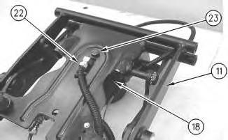
3. Install bolt (23) in order to attach spring assembly (18) to scissor assembly (11). Attach hose assembly (22) to spring assembly (18) .
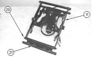
Illustration 4
g00872037
4. Install shaft (20) in order to attach toggle assembly (21) to scissor assembly (11). Tighten the two nuts for shaft (20) to a torque of 15 ± 3 N·m (11 ± 2 lb ft).
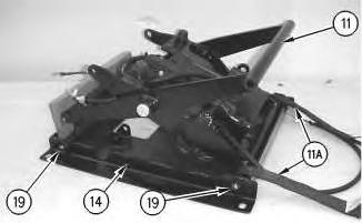
Illustration 5
g00872031
5. Install shaft assemblies (19) in order to attach tether straps (11A) and scissor assembly (11) to housing assembly (14). Tighten the nuts on shaft assemblies (19) to a torque of 20 ± 5 N·m (15 ± 4 lb ft). Install blocking in order to prevent scissor assembly (11) from falling.