

Product: TRACK LOADER
Model: 951B TRACK LOADER 86J
Configuration: 951C TRAXCAVATOR 86J04042-UP (MACHINE) POWERED BY 3304 ENGINE
Disassembly and Assembly
GENERAL INSTRUCTIONS
REG006840001
General Instructions
SMCS - 1405-016
General Instructions
The following instructions will prove helpful to disassemble and assemble machine components. The information should be read and then referred to asnecessary.
Safety
The safety symbols in the manual indicate an item or procedure where the use of caution and safety is necessary. ALWAYS heed these symbols.
Your safety and that of othersisalways the number one consideration when working around machines. Safety isa matter of thoroughly understanding the job to be done and the application of good common sense; not just a matter of "do's" and don'ts."
Cleanliness
Clean the connection and the adjacent area before disconnecting hydraulic, fuel or air lines. As soon asthe disconnection is made, cap, plug or tape the line or opening to prevent entry of foreign material. The same recommendations for cleaning and covering apply when accesscovers or inspection plates are removed.
Clean and inspect all parts. Be sure all passagesand holes are open. Cover all parts to keep them clean. Be sure partsare clean when installed. Leave newparts in their containersuntil ready for assembly.
Removal And Installation
Unless otherwise specified, all removals should be accomplished using an adjustable lifting beam. All supporting members (chainsand cables) should be parallel to each other and as near perpendicular as possible to the top of the object being lifted.
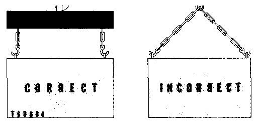
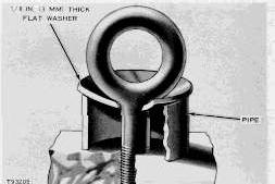
When it is necessary to remove a component on an angle, remember that the capacity of an eyebolt diminishesasthe angle between the supporting members and the object becomesless than 90°. Eyeboltsand brackets should never be bent and should only have stress in tension. A length of pipe and a washer can be used, as shown, to help relieve these stresses on eyebolts.
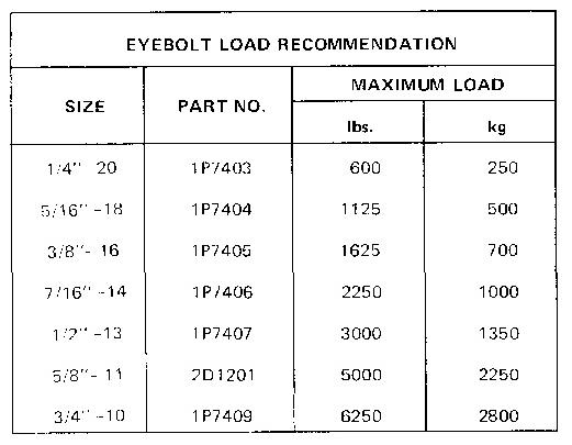
Forged eyeboltsare available. Each size eyebolt hasa maximum load recommendation.
Some removals require the use of lifting fixturesto obtain proper balance and to provide safe handling.
If a part resistsremoval, check to be certain all nuts and bolts have been removed and that an adjacent part is not interfering.
Cleaning And Handling Of Parts
Use caution during removal and installation of parts to prevent damage when handling. Many parts may be used again if not damaged by removal methods. Never discard an expensive part without first cleaning it to see if it can be used again.
Partsthat are to be reused should be protected with a coating of oil or corrosion preventive material until they are installed. Do not store parts outside unless they have corrosion protection and they are covered.
Before installation of newor reusable parts, clean the corrosion preventive material from the machined surfaces. Use a cleaning solvent that will not destroy the material being cleaned (an example is aluminum).
Inspect the parts for damage caused by handling. Many nicksand burrscan be removed with crocus cloth or a fine grain polishing stone.
See the correct Service Manual or Guideline for Reusable Parts for more information.
Disassembly And Assembly
When assembling a machine, complete each step in turn. Do not partially assemble one part and start assembling some other part. Make all adjustments as recommended. Alwayscheck the job after it is completed to see nothing has been overlooked.
First Operation Of A Rebuilt Engine
Use the following procedure:
1. If the diesel engine has a starting engine, use the starting engine to make the engine turn for 10 minutes.
2. Start the diesel engine, then run the engine at low RPM for 10 minutes. Make correct low idle governor adjustment. Check the pressure of the cooling system and the lubrication system. Look for leaks of water and of oil.
3. Run the engine at 3/4 of full RPM with 1/2load for 15 minutes.
4. Run the engine at full RPM and make correct high idle governor adjustment, then run engine at full RPM and with full load for 30 minutes.
Service Tools
Puller Assembly (2 or 3 Arm)
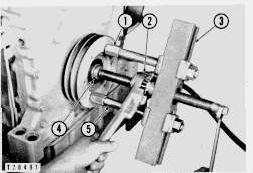
Two or three arm puller assemblies can be used to remove gears, bearing cages, hubs, bearings, shafts, etc.
EXAMPLEOF TOOL INSTALLATION
1. Puller.
EXAMPLEOF TOOL INSTALLATION
1. Puller. 2. Step plate.
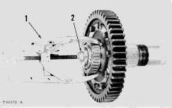
EXAMPLEOF TOOL INSTALLATION
1. Puller. 2. Step plate.
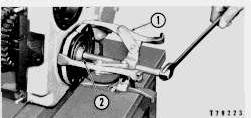
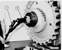
Bearing Pulling Attachment
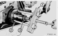
Bearing Pulling Attachments can be used with forcing bolts, to remove shafts, bearings, gears, etc. They can be used with Push-Pullers to provide a variety of pulling combinations.
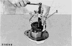
EXAMPLEOF TOOL INSTALLATION
1. Bearing pullerattachment. 2. Forcing screws.
Bearing Cup Pulling Attachment
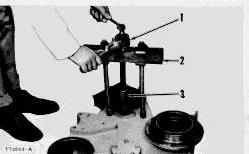
Bearing Cup Pulling Attachments are used to remove bearing racesor cups, sleeve-type bearings, bearings, seats, etc. and can be used with Push Pullers.
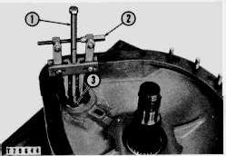
EXAMPLEOF TOOL INSTALLATION
1. Screw. 2. Bearing cup pullerattachment. 3. Step plate.
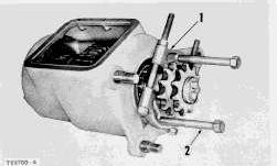
Push Pullers
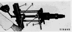
Push Pullers can be used to remove pulleys, gears, shafts, etc., and can be used in a variety of pulling combinations.
This is the sample of the manual
Click on the download link for complete Manual
EXAMPLEOF TOOL INSTALLATION
EXAMPLEOF TOOL INSTALLATION
EXAMPLEOF TOOL INSTALLATION
EXAMPLEOF TOOL INSTALLATION

EXAMPLEOF TOOL INSTALLATION
1. Pushpuller. 2. Bearing cup puller attachment. 3. Reducingadapter.
EXAMPLEOF TOOL INSTALLATION
1. Bearing pullerattachment. 2. Pushpuller. 3. Reducingadapter.
Tool Safety
RULE 1-Always use safe tools.
RULE 2-Keep toolsinsafe condition.
RULE 3-Use the right tool for the job.
RULE 4-Safety sense with tools pays off.
Pressing Parts
When pressing one part into another, use 9M3710 Anti-Seize Compound or a molybdenum disulfide base compound to lubricate the mating surfaces.
Assemble tapered partsdry. Before assembling partswith tapered splines, be sure the splines are clean, dry and free from burrs. Position the parts together by hand to mesh the splinesbefore applying pressure.
If parts which are fitted together with tapered splinesare not tight, inspect the tapered splines and discard if worn.
Bolts And Bolt Torque
A bolt which is too long may "bottom" before the head istight against the part it is to hold. The threads can be damaged when a "long" bolt is removed.
If a bolt is too short, there may not be enough threads engaged to hold the part securely.
Apply proper torque values to all bolts and nuts when assembling Caterpillar equipment. When a specific torque value isrequired, the value is listed in the SPECIFICATION section of the Service Manual. Tighten all other boltsand nuts for general usage, hydraulic valve bodies, or taperlock studs to the torque values given in the charts.
T-T-T Procedure
A torque-turn-tighten (T-T-T) procedure is used in many specificationsand instructions.
1. Clean the bolt and nut threads.
2. Put lubricant on the threadsand the seat face of the bolt and the nut.
3. Turn the bolt or the nut tight according to the torque specification.
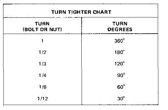
4. Put a location mark on the part and on the bolt or the nut.
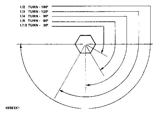
5. Turn the bolt or the nut tighter by the amount of degrees shown in the specifications.
NOTE: The side of a nut or bolt head can be used for reference if a mark can not be put on.
Torque Wrench Extension
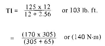
When a torque wrench extension is used with a torque wrench, the torque indication on the torque wrench will be less than the real torque.
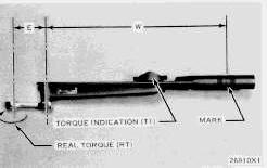
TORQUE WRENCHWITH TORQUE WRENCH EXTENSION
E. Dimension from torque wrench drive axis to torque wrench extension drive axis. W. Dimension from mark onhandle to torque wrenchdrive axis.
1. Put a mark on the handle. Measure the handle from the mark to the axis of the torque wrench drive (W).
2. Measure the torque wrench extension from the torque wrench drive to the axis of the torque wrench extension drive (E).
3. To get correct torque indication (TI) when the real torque (RT) isknown:

Example: W = 12 in. (305 mm); E = 2.56 in. (65 mm); RT (from specifications) = 125 lb. ft. (170 N·m).
4. Hold the torque wrench handle with the longest finger of the hand over the mark on the handle to get the real torque (RT) with low torque indication (TI) on the torque wrench.
Torque Multipliers
The capacity of a torque wrench isincreased when it isused with a torque multiplier. The Tool Guide shows several torque multipliers with different capacities.
5P3508 TORQUE MULTIPLIER 1. Torque wrench. 2. Torque multiplier.
A 1P850 Torque Multiplier is used with the hydraulic cylinder repair stand. An 8H8561 Adapter is needed when a torque wrench with a 1/2 inch (12.7 mm) drive is used with the 1P850 Torque Multiplier.
Chart (5) under the torque multiplier handle has the torque wrench input torque and the torque multiplier output torque.
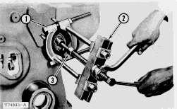
When the T-T-T (torque-turn-tighten) procedure is needed, use 60° protractor (3). The protractor is used with six marks (4) to tighten the nut correctly.

1P850 TORQUE MULTIPLIER (USEDWITH HYDRAULIC CYLINDER REPAIR STAND)
1. Torque wrench. 3. 60° Protractor. 4. Six marks (60°apart). 5. Chart (under handle).
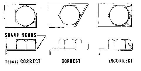
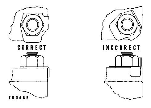
Locks
Flat metal locks must be installed properly to be effective. Bend one end of the lock around the edge of the part. Bend the other end against one flat surface of the nut or bolt head.
Always install newlocks in compartments which house moving parts.
When installing lockwashers on housings made of aluminum, use a flat washer between the lockwasher and the housing.
Lines And Wires
When removing or disconnecting a group of lines or wires, tag each one to assure proper assembly.
Lubrication
Where applicable, fill the compartmentsof the components serviced with the amount, type and grade of lubricant recommended in the Lubrication and Maintenance Guide section of the Service Manual.
Shims
When shims are removed tie them together and identify them as to location. Keep shims clean and flat until they are reinstalled.
Bearings
Anti-Friction Bearings
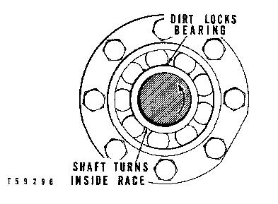
When an anti-friction bearing is removed, cover it to keep out dirt and abrasives. Wash bearings in nonflammable cleaning solution and allow them to drain dry. The bearing may be dried with compressed air but DONOT SPIN THE BEARING.
Discard the bearings if the races and balls or rollersare pitted, scored or burned. If the bearing is serviceable, coat it with oil and wrap it in clean paper. Do not unwrap newbearings until time of installation.
The life of an anti-friction bearing will be shortened if not properly lubricated.
Double Row, Tapered Roller
Double row, tapered roller bearingsare precision fit during manufacture and the components are not interchangeable. The cups, conesand spacers are usually etched with the same serial number and letter designator. If no letter designatorsare found, wire the components together to assure correct installation. Reusable bearing components should be installed in their original positions.
Heating Bearings
Bearings which require expansion for installation should be heated in oil not to exceed 250° F. (121° C.). When more than one part isheated to aid in assembly, they must be allowed to cool and then pressed together again. Parts often separate as they cool and shrink.
Installation
Lubricate newor used bearings before installation. Bearings that are to be preloaded must have a film of oil over the entire assembly to obtain accurate preloading. When installing a bearing, spacer or washer against a shoulder on a shaft, be sure the chamfered side is toward the shoulder.
When pressing bearings into a retainer or bore, apply pressure to the outer race. If the bearing is pressed on the shaft, apply pressure on the inner race.
Preload
Preload is an initial force placed on the bearing at the time of assembly.
Determine preload or end clearance from the SPECIFICATIONS. Care should be exercised in applying preload. Misapplication of preload to bearingsrequiring end clearance can result in bearing failure.
Sleeve Bearings
DO NOT INSTALL SLEEVE BEARINGS WITHA HAMMER. Use a press if possible and apply the pressure directly in line with the bore. If it is necessary to drive on a bearing use a driver or a bar with a smooth flat end. If a sleeve bearing has an oil hole, align it with the oil hole in the mating part.
Gaskets
Be sure the holes in the gaskets correspond with the lubricant passages in the mating parts. If it is necessary to make gaskets, select stock of the proper type and thickness. Be sure to cut holes properly. Blank gaskets can cause serious damage.
Batteries
Clean batteries by scrubbing with a solution of baking soda and water. Rinse with clear water. After cleaning, dry thoroughly, coat terminalsand connections with anti-corrosion compound or grease.
If an engine is not to be used for a long period of time, remove the batteries. Store them in a warm, dry place, on wooden shelves. Never store on concrete. A small charge should be introduced periodically to keep the specific gravity rating at recommended level.
Brake Linings
Replace brake liningsbefore they have worn enough for rivet heads to contact and score the brake drums.
Seals
Duo-Cone Floating Seals
Floating ring seals have highly finished surfacesand are held together by toric sealing rings. The flexibility of the toric sealing ringsmakes the floating ring seals self aligning and compensates for wear on the metal faces.
During disassembly, tape the metal floating ring sealstogether so they will be kept in matched sets. Always install the metal floating ring seals in pairs; that is, two new seals together or two seals that have previously run together. Never reinstall a used toric sealing ring.
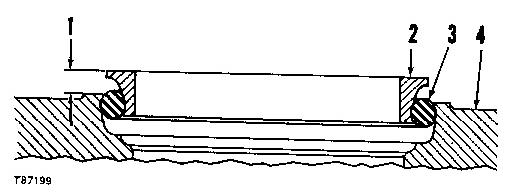
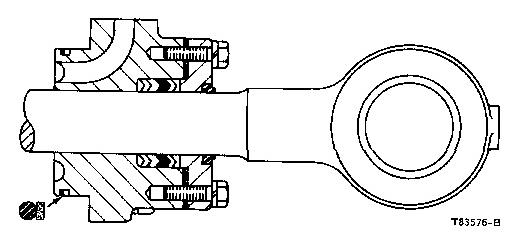
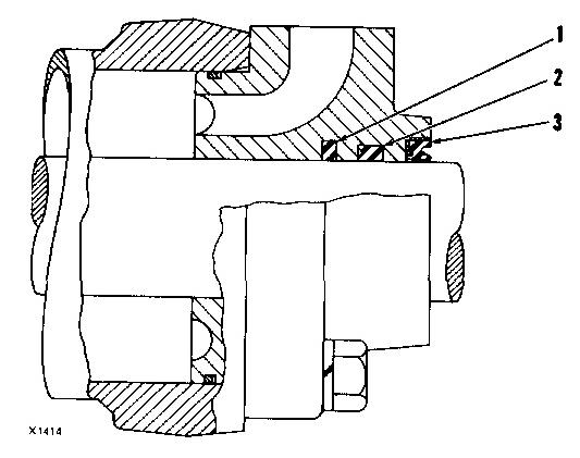
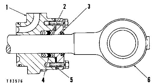
CORRECT INSTALLATION
1. Dimension. 2. Metal floating ringseal. 3. Rubber toric sealing ring. 4. Toric sealing ringretainer.
The illustration shows the dimension (1) to be checked, the metal floating ring seal (2), the rubber toric sealing ring (3) and the toric sealing ring retainer (4). The dimension must be uniform around the entire circumference of the floating ring seal. Check the dimension at 90° intervals.
Handle all partswith care to avoid nicks. File smooth any parts, other than the sealing faces, that have nicks that may make assembly difficult or questionable. Wash used parts. Use a wire brush to clean dirt or rust from the bore of the seal retainers to assure they are clean and smooth. Remove all oil or the protective coating from floating ring seals and retainers with a nonflammable cleaning solvent. Be sure the ramp on the retainers and on the floating ring seals is dry.
Check the ramps for tool marks and nicks. On used parts, remove dirt or rust deposits from the ramps Smooth the surface with emery cloth.
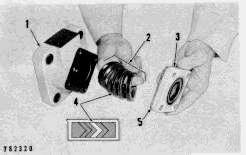
Install newtoric sealing ringsor floating ring seals. Seat the toric sealing ring uniformly in the relief of the ring seal. Be sure the toric sealing ring isnot twisted. It must set straight against the lip which keeps it from falling off the floating ring seal.
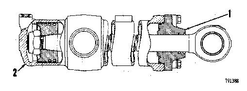
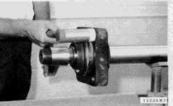
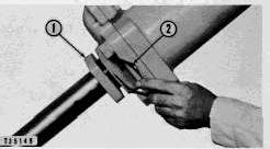
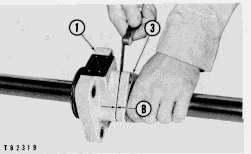
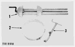
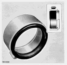
Duo-Cone floating seal installation tools are available for varioussize seals. See the Power Train Tools section of the Tool Guide for a list of installation tools. A typical installation tool isshown in the illustration.
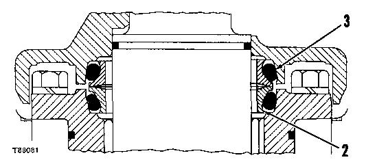
DUO-CONESEAL INSTALLED
2. Metal floating ring seal. 3. Rubber toric sealing ring.
If an installer tool is not used, install the toric sealing ring and floating ring seal asan assembly by pressing on the toric sealing ring. Use finger pressure only. Be sure the toric sealing ring isseated uniformly in the recess of both the floating ring seal and the retainer. Make sure it sets in the bore straight and against the lip that keepsit from falling out of the retainer. DO NOT USE A SCREWDRIVER OR STICK TO ASSEMBLE THE TORIC SEALING RINGIN THE RETAINER.
Before assembling floating ring seals together, wipe faces of seals with lint-free tissue to remove any foreign material and fingerprints. Place one drop of oil on the cleaning tissue and coat the sealing surfaces of the seals. Be careful to prevent any oil from contacting the toric sealing ring or itsmating surfaces.
Lip-Type Seals
Generally the toe or spring-loaded lip of an oil seal faces the oil being sealed or the oil having the higher pressure. The toe or lip of a grease seal facesaway from the lubricant being sealed. Unless otherwise specified, use the preceding rules for installing lip-type seals.
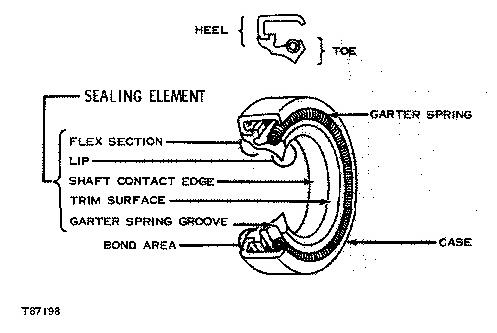
The main partsof a lip-type seal are the case, sealing element, and garter spring. The picture illustrates the construction of a simple lip-type seal. The cross sections show the terms "heel" and "toe" used to identify the sidesof various types of seals.

Lubricate the lipsof lip-type seals before installation. Use the same type lubricant in which the seal will be operating. Do not use grease on any seal except a grease seal.
If, during installation, the seal lip must pass over a shaft that has splines, a keyway, rough surface or a sharp edge, the lip can be easily damaged. Shim stock or other such material can be formed around the area to provide a smooth surface over which to slide the seal.