


Product: WHEEL LOADER
Model: 950G II WHEEL LOADER AYL
Configuration: 950G II Wheel Loader AYL00001-UP (MACHINE) POWERED BY 3126 Engine
Disassembly and Assembly
Comfort Series Seat For Caterpillar Machines
-RENR2165-12
i01723170
Air Suspension With Air Valve Knob Height AdjustmentAssemble
SMCS - 7324-016-AJ
Assembly Procedure
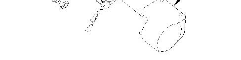
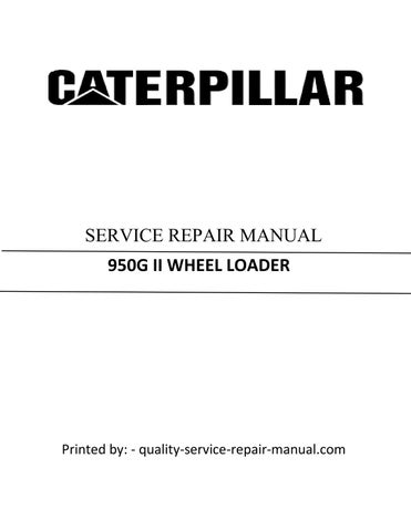
Illustration 1 g00891451
1. Install compressor assembly (25) to mount (26). Make sure that compressor assembly (25) is seated firmly in mount (26) .
2
2. Install bolts (24) in order to attach compressor assembly (25) to scissor assembly (11) .
3
Improper assembly of parts that are spring loaded can cause bodily injury.
To prevent possible injury, follow the established assembly procedure and wear protective equipment.
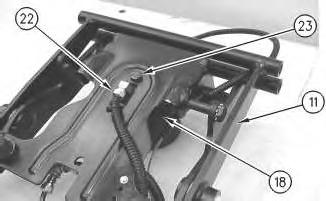
3. Install bolt (23) in order to attach spring assembly (18) to scissor assembly (11). Attach hose assembly (22) to spring assembly (18) .

Illustration 4
g00872037
4. Install shaft (20) in order to attach toggle assembly (21) to scissor assembly (11). Tighten the two nuts for shaft (20) to a torque of 15 ± 3 N·m (11 ± 2 lb ft).

Illustration 5
g00872031
5. Install shaft assemblies (19) in order to attach tether straps (11A) and scissor assembly (11) to housing assembly (14). Tighten the nuts on shaft assemblies (19) to a torque of 20 ± 5 N·m (15 ± 4 lb ft). Install blocking in order to prevent scissor assembly (11) from falling.
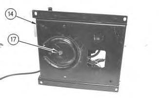
Illustration 6
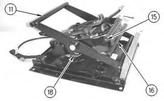
Illustration 7
g00872020
6. Install screw (17) in order to attach housing assembly (14) to spring assembly (18) .
7. Install shaft (15) in order to attach toggle assembly (16) to scissor assembly (11). Tighten the two nuts for shaft (15) to a torque of 15 ± 3 N·m (11 ± 2 lb ft).
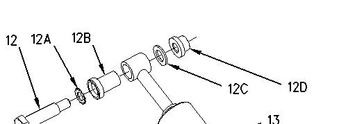
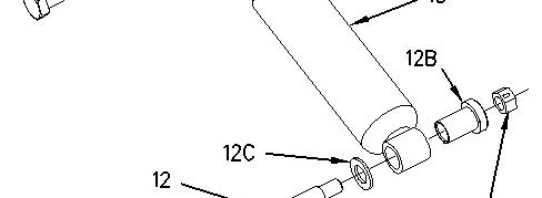
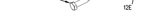
Illustration 8 g00897454
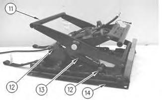
Illustration 9 g00872007
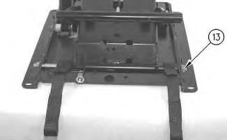
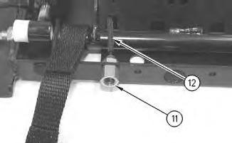
8. Install bearings (12B) to shock absorber (13) .
9. Install bolts (12) in order to attach shock absorber (13) to scissor assembly (11) and housing assembly (14). Remove the blocking.
Note: Illustration 8 shows the location of lockwasher (12A), bearings (12B), washers (12C), nut (12D), and locknut (12E) .
10. Repeat Steps 8 and 9 if the seat is equipped with a shock absorber on the opposite side.
10
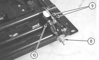
11. Connect harness assemblies (9) and hose assembly (10) to air valve (8) .
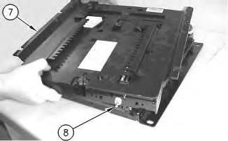
Illustration 11
12. Position air valve (8) to upper housing assembly (7). Position upper housing assembly (7) to the seat.
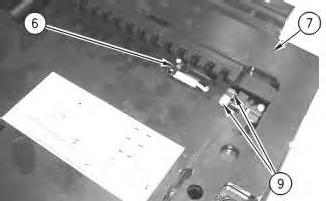
Illustration 12 g00871951
13. Install cable strap (6) in order to secure harness assemblies (9) to upper housing assembly (7) .
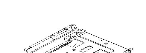
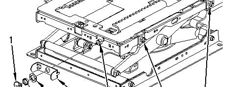

Illustration 13 g00876043
14. Install shaft assemblies (5). Tighten the nuts for shaft assemblies (5) to a torque of 20 ± 5 N·m (15 ± 4 lb ft).
15. Position plate (4) to the seat. Install lockwasher (3A) and nut (3) in order to secure air valve (8) to the seat. Tighten the setscrew in adjustment knob (1) in order to secure adjustment knob (1) to air valve (8) .

Illustration 14
16. Install boot (2) to the seat.
g00871915
Copyright 1993 - 2021 Caterpillar Inc. All Rights Reserved. Private Network For SIS Licensees. Fri Nov 12 21:42:27 UTC+0530 2021
Product: WHEEL LOADER
Model: 950G II WHEEL LOADER AYL
Configuration: 950G II Wheel Loader AYL00001-UP (MACHINE) POWERED BY 3126 Engine
Disassembly and Assembly
Comfort Series Seat For Caterpillar Machines
i01693748
Air Suspension with Air Valve Knob Height AdjustmentDisassemble
SMCS - 7324-015-AJ
Disassembly Procedure
The air spring of the air suspension is filled with air pressure.
Prior to disassembly, release the air pressure in the air spring. Failure to do so could result in personal injury.
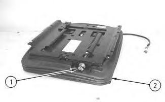
Illustration 1 g00871915
1. Pull adjustment knob (1) in order to release the air from the seat.
2. Remove boot (2) .
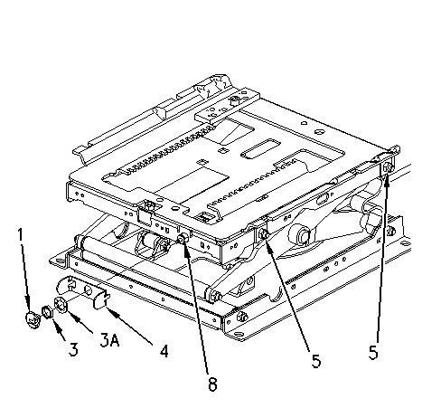
Illustration 2
g00876043
3. Loosen the setscrew in adjustment knob (1) and remove adjustment knob (1). Remove nut (3) and lockwasher (3A). Remove plate (4) from air valve (8) .
4. Remove shaft assemblies (5) .
Illustration 3
5. Remove cable strap (6) in order to disconnect harness assemblies (9) from upper housing assembly (7) .
Illustration 4
g00871971
6. Lift upper housing assembly (7) and push air valve (8) away from upper housing assembly (7). Remove upper housing assembly (7) .
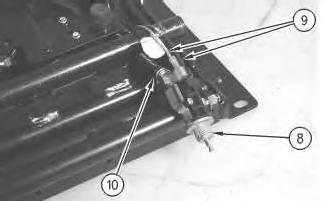
Illustration 5
g00871994
7. Disconnect harness assemblies (9) and hose assembly (10) from air valve (8) .
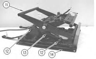
Illustration 6
g00872007
Illustration 7 g00897454
8. Raise scissor assembly (11) and install blocking in order to prevent scissor assembly (11) from falling.
9. Remove bolts (12) in order to remove shock absorber (13) from scissor assembly (11) and housing assembly (14) .
10. Remove bearings (12B) from shock absorber (13) .
Note: Illustration 7 shows the location of lockwasher (12A), bearings (12B), washers (12C), nut (12D), and locknut (12E) .
11. Repeat Steps 9 and 10 if the seat is equipped with a shock absorber on the opposite side.
Illustration 8
g00872020
Illustration 9
g00872029
12. Remove shaft (15) in order to remove toggle assembly (16) from scissor assembly (11) .
13. Remove screw (17) in order to disconnect spring assembly (18) from housing assembly (14) .
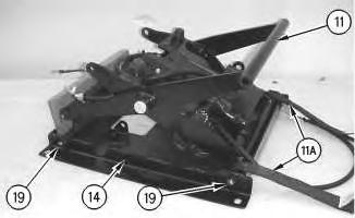
Illustration 10
g00872031
14. Remove shaft assemblies (19) in order to remove scissor assembly (11) from housing assembly (14) and tether straps (11A) .
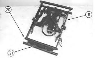
Illustration 11
g00872037
15. Remove shaft (20) in order to remove toggle assembly (21) from scissor assembly (11) .

Illustration 12
g00872043
Personal injury can result from being struck by parts propelled by a released spring force.
Make sure to wear all necessary protective equipment.
Follow the recommended procedure and use all recommended tooling to release the spring force.
16. Remove hose assembly (22) and bolt (23) in order to remove spring assembly (18) from scissor assembly (11) .
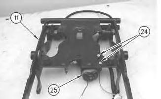
Illustration 13 g00872046
17. Remove bolts (24) in order to remove compressor assembly (25) from scissor assembly (11) .
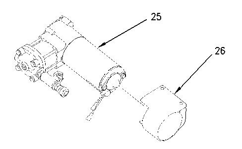
Illustration 14 g00891451
18. Remove compressor assembly (25) from mount (26) .
Copyright 1993 - 2021 Caterpillar Inc. All Rights Reserved. Private Network For SIS Licensees. Fri Nov 12 21:42:07 UTC+0530 2021
Product: WHEEL LOADER
Model: 950G II WHEEL LOADER AYL
Configuration: 950G II Wheel Loader AYL00001-UP (MACHINE) POWERED BY 3126 Engine
Disassembly and Assembly
Comfort Series Seat For Caterpillar Machines
Air Suspension With System Air - Assemble
SMCS - 7324-016-AJ
Assembly Procedure
i01518491
1. Check the condition of all parts of the air suspension. If any of the parts are worn or damaged, install new parts.
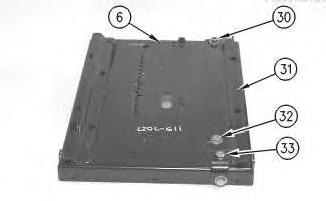
Illustration 1
Typical Example
g00275862
2. Position slider track (31) on upper housing (6). Install bolt (33), two bolts (32) and the washers. Tighten bolts (33) and (32) to a torque of 30 ± 7 N·m (22 ± 5 lb ft). Install locknut (30) and the washer. Tighten locknut (30) to a torque of 40 ± 8 N·m (30 ± 6 lb ft).
2
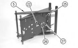
Illustration 3
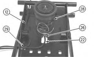
3. Position air spring (28) on scissor assembly (5). Apply 9S-3263 Thread Lock on bolt (27). Install bolt (27) that holds the air spring to scissor assembly (5). Tighten bolt (27) to a torque of 40 ± 8 N·m (30 ± 6 lb ft).
4. Position tubes (12) and (22) on scissor assembly (5). Install new tie-wraps (29) in order to secure the tubes to the scissor assembly.
5. Connect tube (22) to fitting (26) on air spring (28). Install two bumpers (25) .
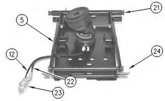
Illustration 4
6. Apply 5N-5561 Lubrication Compound on scissor assembly (5) at the point of installation for two rollers (24). Install two rollers (24) and two bearings (21). Connect tubes (12) and (22) to valve assembly (23) .
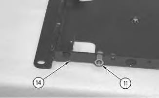
Illustration 5
7. Install fitting (11) in lower housing (14) .
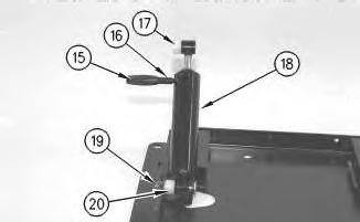
Illustration 6
Typical Example
g00275855
8. Install two bearings (17) and (20), damper (18), the pin and locknut (19). Tighten locknut (19) to a torque of 30 ± 7 N·m (22 ± 5 lb ft). Install shaft (7) and cap (15) on damper (18) .
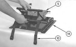
Illustration 7
g00275854
9. Install scissor assembly (5) into lower housing (14). Install two tether belts (10) .
8
10. Install the lower shaft assembly. Install locknut (13) and the lock washer. Tighten locknut (13) to a torque of 40 ± 8 N·m (30 ± 6 lb ft).
9
11. Connect tube (12) to fitting (11) .
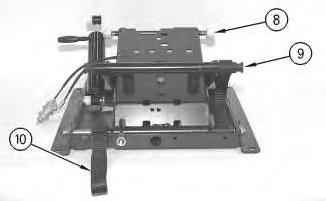
Illustration 10
Typical Example
g00275849
12. Install two tether belts (10) and two bearings (9). Apply 5N-5561 Lubrication Compound on the scissor assembly at the point of installation for rollers (8). Install rollers (8) on the scissor assembly.
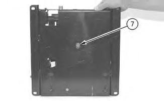
Illustration 11
g00275848
13. Apply 9S-3263 Thread Lock on screw (7). Install screw (7) in order to secure the air spring, which is not shown. Tighten the screw to a torque of 4.3 ± 1 N·m (38 ± 9 lb in).
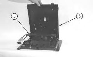
Illustration 12
g00275846
14. Install upper housing (6) on scissor assembly (5) .
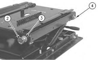
Illustration 13
Typical Example
g00275845
15. Install the upper shaft assembly, locknut (4) and the lock washer. Tighten the locknut to a torque of 40 ± 8 N·m (30 ± 6 lb ft). Install locknut (4) and the lock washer. Apply 9S-3263 Thread Lock on the setscrew of knob (2). Install knob (2) and the setscrew.
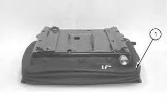
Illustration 14 g00275844
Typical Example
16. Install boot (1) .
17. Install the seat on the air suspension. Install the seat in the machine.
Copyright 1993 - 2021 Caterpillar Inc. All Rights Reserved. Private Network For SIS Licensees. Fri Nov 12 21:43:01 UTC+0530 2021
Product: WHEEL LOADER
Model: 950G II WHEEL LOADER AYL
Configuration: 950G II Wheel Loader AYL00001-UP (MACHINE) POWERED BY 3126 Engine
Disassembly and Assembly
Comfort Series Seat For Caterpillar Machines
Air Suspension With System Air - Disassemble
SMCS - 7324-015-AJ
Disassembly Procedure
1. Remove the seat from the machine. Separate the seat from the air suspension.
Illustration 1
Typical Example
2. Remove boot (1) .
g00275844
i01518481
This is the sample of the manual click on the download link for complete manual