
Note: Use Bookmarks panel to navigate

Product: WHEEL LOADER
Model: 950G WHEEL LOADER 5MW
Configuration: 950G WHEEL LOADER 5MW00701-UP (MACHINE) POWERED BY 3126 ENGINE
Disassembly and Assembly
950G and 962G Wheel Loaders and IT62G Integrated Toolcarrier Machine Systems
i01640919
Ride Control Accumulator - Remove and Install
SMCS - 5077-010
Removal Procedure
Start By:
A. Connect the steering frame lock. Refer to Disassembly and Assembly, "Steering Frame LockSeparate and Connect".
B. Release the pressure in the hydraulic system. Refer to Disassembly and Assembly, "System Pressure - Release".
NOTICE
Care must be taken to ensure that fluids are contained during performance of inspection, maintenance, testing, adjusting and repair of the product. Be prepared to collect the fluid with suitable containers before opening any compartment or disassembling any component containing fluids.
Refer to Special Publication, NENG2500, "Caterpillar Tools and Shop Products Guide" for tools and supplies suitable to collect and contain fluids on Caterpillar products.
Dispose of all fluids according to local regulations and mandates.
Personal injury can result from hydraulic oil pressure and hot oil.
Hydraulic oil pressure can remain in the hydraulic system after the engine has been stopped. Serious injury can be caused if this pressure is not released before any service is done on the hydraulic system.
Make sure all of the attachments have been lowered, oil is cool before removing any components or lines. Remove the oil filler cap only when the engine is stopped, and the filler cap is cool enough to touch with your bare hand.
Personal injury can result from the sudden release of high pressure oil.
Be sure the engine has been shut off for a minimum of five minutes to be sure that the accumulator pressure is zero.
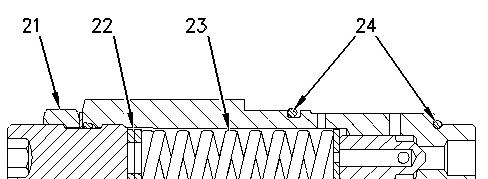
The accumulator is filled with dry nitrogen. Do not loosen or remove the valve or cap from the top of the accumulator. A purge screw at the bottom of the accumulator can be used to release the pressure that is left in the system.
Note: Put identification marks on the hose assembly and plug the hose assembly. This helps to prevent fluid loss and this helps to keep contaminants from entering the system.
Note: The ride control accumulator is located inside the front loader frame.
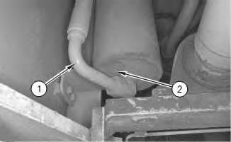
Illustration 1
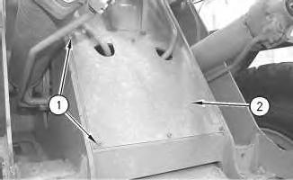
1. Disconnect hose assembly (1) .
2. Remove two bolts (2) .
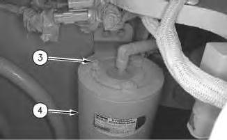
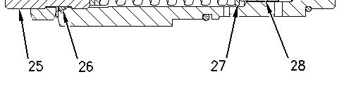
Illustration 2
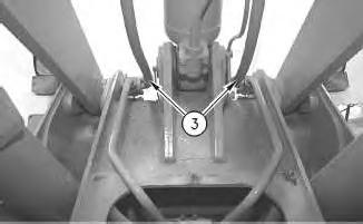
3. Remove bolts (3) .
4. Use two persons in order to remove ride control accumulator (4). The weight of the ride control accumulator is 34 kg (75 lb).
Installation Procedure
This is the sample of the manual click on the download link for complete manual
Illustration 3
1. Use two persons in order to install ride control accumulator (4). The weight of the ride control accumulator is 34 kg (75 lb).
2. Install bolts (3) .
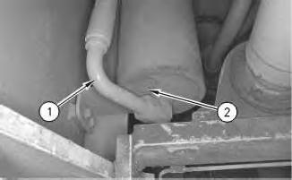
Illustration 4
3. Install two bolts (2) .
g00354935
4. Connect hose assembly (1) . End By: Separate the steering frame lock. Refer to Disassembly and Assembly, "Steering Frame Lock - Separate and Connect".

Product: WHEEL LOADER
Model: 950G WHEEL LOADER 5MW
Configuration: 950G WHEEL LOADER 5MW00701-UP (MACHINE) POWERED BY 3126 ENGINE
Disassembly and Assembly 950G and 962G Wheel Loaders and IT62G Integrated Toolcarrier Machine Systems
Main Control Valve and Mounting Plate - Install
SMCS - 5051-012
S/N - BDP1-UP
Installation Procedure
Table 1
B 8S-9906 Ratchet Puller 1
C 8S-9906 Ratchet Puller 1
Note: The main control valve and mounting that is used in machines with Pilot Hydraulic systems and machines with Electro-Hydraulic controls are similar. Therefore, both assemblies can be installed in the same manner.
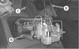
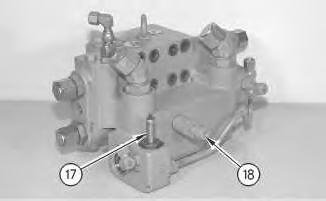
Illustration 1
Typical Example
g00352846
1. Install Tooling (B) and Tooling (C) on the main control valve, as shown. The combined weight of the main control valve and of mounting plate (15) is 170 kg (375 lb).
Note: Use Tooling (B) in order to control the rearward movement.
Note: Use Tooling (C) in order to control the upward movement.
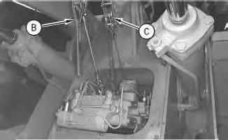
Illustration 2
Typical Example
2. Install the plate assembly so that the mounting plate rests on the front loader frame, as shown.
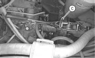
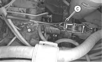
Illustration 3
Typical Example
g00352844
3. Reposition Tooling (C) in order to support the rear of the mounting plate, as shown.
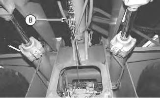
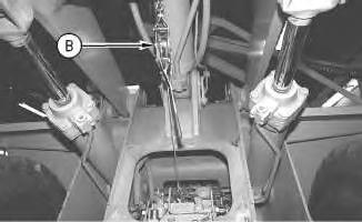
Illustration 4
Typical Example
g00352843
4. Use Tooling (B) and Tooling (C) to install the main control valve and mounting plate (15) in the original position.

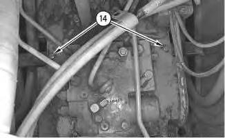
Illustration 5
Typical Example
Rear Mounting Bolts
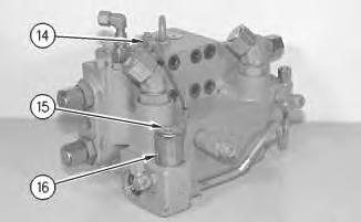
5. Install four mounting bolts (14) .
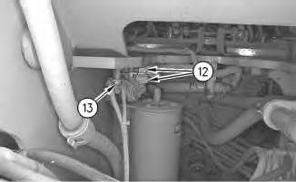
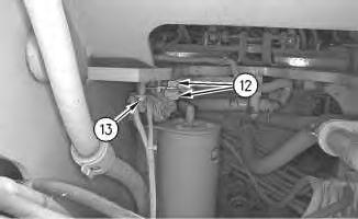
Illustration 6
Typical Example
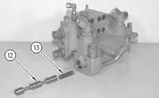
6. Install the wiring clip and bolt (13) .
7. Connect two electrical connectors (12) .
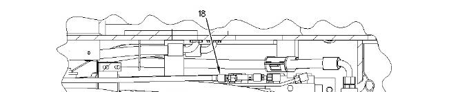
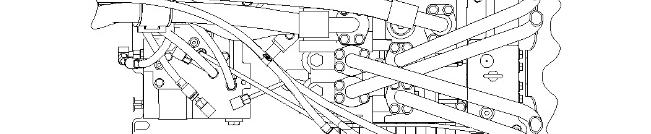

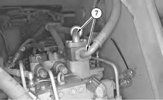
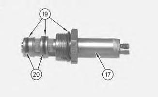
Illustration 7 g00755814
8. Connect pilot hoses (18) and (19) .
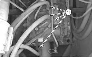
Illustration 8 g00352839
Typical Example
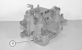
9. Connect four pilot hoses (11) to the pilot valve.
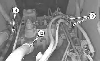
Illustration 9
Typical Example
Rear View
g00352837
10. Connect hydraulic hose assembly (10), pilot hose (8), and pilot hoses (9) .
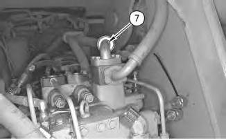
Illustration 10
Typical Example
g00757382
11. Connect two hose assemblies (7) to the main control valve assembly.
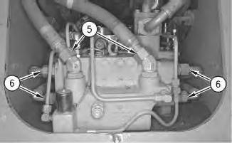
Illustration 11
Typical Example
g00352835
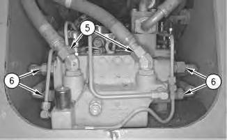
12. Connect two hydraulic hose assemblies (5) to the diverter valve.
13. Install four hydraulic hose assemblies (6) .
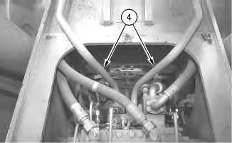
Illustration 12
Typical Example
14. Install hydraulic tube assemblies (4) .
g00352834
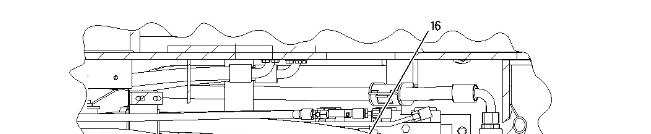
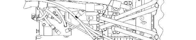

Illustration 13 g00756999
15. Install hydraulic tube assemblies (16) and (17) .

Illustration 14 g00352832
Typical Example
16. Install two hydraulic hose assemblies (3) .

Illustration 15
Typical Example
17. Install front guard (2) and six nuts (1) .
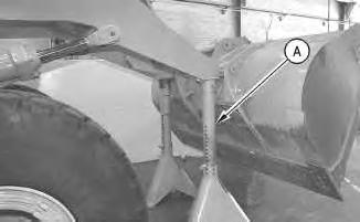
Illustration 16
18. Use the hydraulics to raise the loader arms. Remove Tooling (A) .
End By: Separate the steering frame lock. Refer to Disassembly and Assembly, "Steering Frame LockSeparate and Connect".
Copyright 1993 - 2022 Caterpillar Inc. All Rights Reserved.
Network For SIS Licensees. Mon Sep 12 11:00:24 UTC+0530 2022
Product: WHEEL LOADER
Model: 950G WHEEL LOADER 5MW
Configuration: 950G WHEEL LOADER 5MW00701-UP (MACHINE) POWERED BY 3126 ENGINE
Disassembly and Assembly
950G and 962G Wheel Loaders and IT62G Integrated Toolcarrier Machine Systems
Main Control Valve and Mounting Plate - Install
SMCS - 5051-012
S/N - 2JS1-UP
S/N - 3BS1-UP
S/N - 3JW1-UP
S/N - 4BS1-UP
S/N - 4PW1-UP
S/N - 5AS1-UP
S/N - 5FW1-UP
S/N - 5MW1-UP
S/N - 5RS1-UP
S/N - 6EW1-UP
S/N - 6HW1-UP
S/N - 6NS1-UP
S/N - 7BW1-UP
S/N - 8JW1-UP
i01758445