Product: WHEEL LOADER
Model: 938H WHEEL LOADER LKM
Configuration: 938H Wheel Loader LKM00001-UP (MACHINE) POWERED BY C6.6 Engine
Disassembly and Assembly
C6.6 Engines for Caterpillar Built Machines Media Number
Accessory Drive - Remove and Install
SMCS - 1207-010
Removal Procedure Table 1
Keep all partsclean from contaminants.
Contaminants may cause rapid wear and shortenedcomponent life.
NOTICE
Care must be taken to ensure that fluids are containedduring performance of inspection, maintenance, testing, adjusting and repair of the product. Be prepared to collect the fluid with suitable containers
i02786793
before opening any compartment or disassembling any component containing fluids.
Dispose of all fluids according to local regulations and mandates.
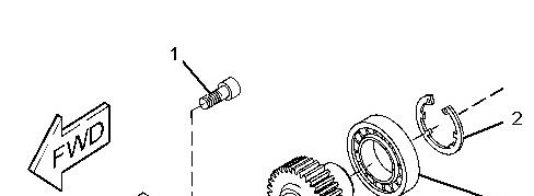
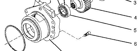
Illustration 1
Typicalexample
g01269954
1. Remove allen head screw(1) from accessory drive housing (8). Remove allen head screws (6) from accessory drive housing (8).
2. Remove accessory drive housing (8) from the front housing.
3. If necessary, followSteps3.a through 3.c in order to disassemble the accessory drive.
a. Remove circlip (2) from accessory drive housing (8).
b. Place accessory drive housing (8) onto a suitable support. Press the assembly of gear (4) and bearings(3) and (5) out of accessory drive housing (8). Use Tooling (A) in order to remove bearings (3) and (5) from gear (4).
c. Remove O-ring seal (7) from accessory drive housing (8).
This is the sample of the manual click on the download link for complete manual
Installation Procedure
Table 2
Required Tools
Tool
B 7M-7456
C 207-1601
D 9S-3263
Bearing Mount Compound -
Rubber Lubricant 1
Thread Lock Compound 1
NOTICE
Keep all partsclean from contaminants.
Contaminants may cause rapid wear and shortenedcomponent life.
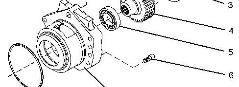
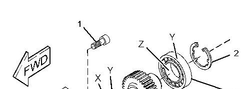
Illustration 2 g01264852
Typicalexample
1. If necessary, followSteps1.a through 1.e in order to assemble the accessory drive.
a. Inspect the condition of the teeth and the splinesof gear (4) for wear or damage. Inspect bearings (3) and (5), circlip (2), and the front housing for wear or damage. Replace any componentsthat are worn or damaged.
b. Apply a small continuousbead of Tooling (B) to inner surface (X) of bearing (5). Place the gear shaft on a suitable support. Press on the inner race of bearing (5) until the bearing (5) is against the shoulder of gear (4). Remove any excesssealant.
c. Apply a small continuousbead of Tooling (B) to inner surface (Z) of bearing (3). Place the inner race of bearing (3) onto a suitable support. Press the shaft of gear (4) into bearing (3) until the shoulder of the gear isagainst the bearing. Remove any excess sealant.
d. Apply a small continuousbead of Tooling (B) to the outer surface (Y) of bearings (3) and (5). Place accessory drive housing (8) on a suitable support. Press the assembly of the gear into the accessory drive housing. Ensure that bearing (5) is against the front face of the recessin accessory drive housing (8). Remove any excess sealant.
e. Install circlip (2) into the groove in accessory drive housing (8). Ensure that circlip (2) is correctly positioned in the groove.
2. Lightly lubricate a new O-ring seal (7) with Tooling (C). Install the O-ring seal into the groove in accessory drive housing (8).
3. Inspect the bore in the front housing for damage. If necessary, replace the front housing. Refer to Disassembly and Assembly, "Housing (Front) - Remove" and Disassembly and Assembly, "Housing (Front) - Install".
4. Lightly lubricate bearing (3), bearing (5), and gear (4) with clean engine lubricating oil. Install the assembly of the accessory drive to the front housing. Ensure that the flange on the accessory drive housing is flush with the front housing.
5. Apply Tooling (D) to allen head screws (1) and (6). Install allen head screws (1) and (6) to accessory drive housing (8).
6. Tighten the allen head screws to a torque of 22 N·m (16 lb ft).
7. Ensure that there is tactile backlash between the idler gear and the accessory drive gear.
Copyright 1993 - 2021 Caterpillar Inc. All Rights Reserved. Private Network For SIS Licensees. Sat Apr 24 21:04:10 UTC+0530 2021
Product: WHEEL LOADER
Model: 938H WHEEL LOADER LKM
Configuration: 938H Wheel Loader LKM00001-UP (MACHINE) POWERED BY C6.6 Engine
Disassembly and Assembly
C6.6 Engines for Caterpillar Built Machines
Air Compressor - Remove and Install
SMCS - 1803-010
Removal Procedure
Table 1 RequiredTools
(1) The Crankshaft Turning Tool is usedon the front pulley. (2) This Tool is usedin theaperture for the electricstarting motor.
Note: Either Tooling (A) can be used. Use the Tooling that is most suitable.
NOTICE
Care must be taken to ensure that fluids are containedduring performance of inspection, maintenance, testing, adjusting and repair of the product. Be prepared to collect the fluid with suitable containers before opening any compartment or disassembling any component containing fluids.
i05194955
Dispose of all fluids according to local regulations and mandates.
NOTICE
Keep all partsclean from contaminants.
Contaminants may cause rapid wear and shortenedcomponent life.
Note: Put identification marks on all hoses, on all hose assembliesand on all tube assembliesfor installation purposes. Plug all hose assembliesand tube assemblies. Plugging hose assemblies and tube assemblies helpsto prevent fluid loss and helps to keep contaminants from entering the system.
Do not disconnect the air lines until the air pressure in the system is at zero. If hose is disconnected under pressure itcancause personal injury.
1. Release the pressure from the air system. Refer to the Original Equipment Manufacture (OEM) for the correct procedure.
2. If the engine is equipped with a hydraulic pump on the rear of the air compressor, remove the hydraulic pump. Refer to the OEM for the correct procedure.
3. Drain the coolant from the cooling system into a suitable container for storage or for disposal. Refer to Operation and Maintenance Manual, "Cooling System Coolant - Change" for the correct draining procedure.
4. Use Tooling (A) in order to rotate the crankshaft so that number one piston is at the top center position on the compression stroke. Refer to Systems Operation, Testing and Adjusting, "Finding Top Center Position for No.1 Piston".
Note: The air compressor must be timed with the engine in order to minimize engine vibration.
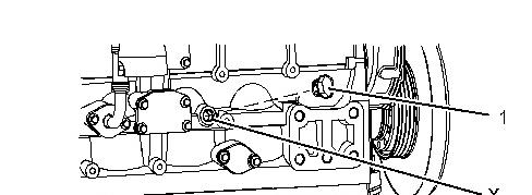
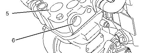
Illustration 1 g01353468
Typicalexample
5. Remove plug (1) from the cylinder block. Install Tooling (B) into Hole (X) in the cylinder block. Use Tooling (B) in order to lock the crankshaft in the correct position.
Note: Do not use excessive force to install Tooling (B). Do not use Tooling (B) to hold the crankshaft during repairs.
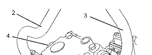
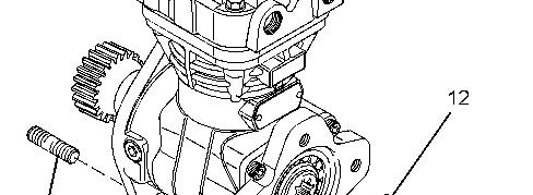
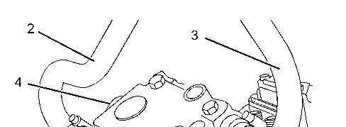
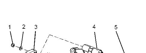
Illustration 2 g01353469
Typicalexample
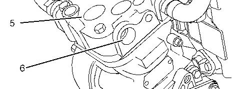
Illustration 3 g01353470
Typicalexample
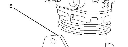
6. Disconnect coolant hose (2) and hose (3) from air compressor (5).
7. Disconnect the air linesfrom port (4) and port (6).
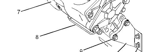
8. Remove tube assembly (8) from air compressor (5) and from the cylinder block.
9. Remove bolts (9) and bolts(11) from support bracket (10) and remove the support bracket.
10. Support air compressor (5). Remove nuts(14) and remove the air compressor from front housing (7).
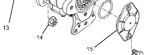
Illustration 4 g01353471
Typicalexample
11. Remove O-ring seal (19) from air compressor (5).
12. If necessary, remove bolts(16) and remove plate (15). Remove O-ring seal (12) from plate (15). Refer to Illustration 3.
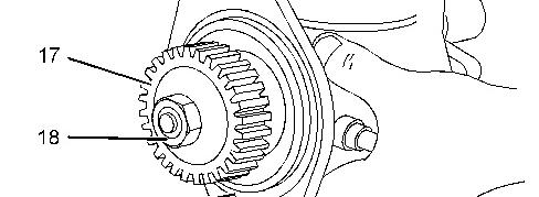
13. If necessary, followStep 13.a through Step 13.c in order to remove gear (17) from air compressor (5).
a. Use a suitable tool in order to prevent gear (17) from rotating.
b. Remove nut (18) and remove the spring washer.
c. Use Tooling (C) in order to remove gear (17) from the crankshaft of air compressor (5).
Installation Procedure
Table 2
B
D 4C-9506 Retaining Compound 1
E 1U-6396 O-ring Assembly Compound 1
NOTICE
Keep all partsclean from contaminants.
Contaminants may cause rapid wear and shortenedcomponent life.
NOTICE
Care must be taken to ensure that fluids are containedduring performance of inspection, maintenance, testing, adjusting and repair of the product. Be prepared to collect the fluid with suitable containers before opening any compartment or disassembling any component containing fluids.
Dispose of all fluids according to local regulations and mandates.
Illustration 5 g01353471
Typicalexample
1. If necessary, followStep 1.a through Step 1.b in order to install gear (17) to air compressor (5).
a. Ensure that the shaft of air compressor (5) is clean and dry. Ensure that gear (17) is clean and free from damage.
b. Install gear (17) and a new spring washer to the shaft of air compressor (5).
c. Apply Tooling (D) to the threads of the shaft. Install nut (18) to the shaft of air compressor (5).
d. Use a suitable tool in order to prevent gear (17) from rotating as nut (18) is tightened. Tighten the nut to a torque of 120 N·m (89 lb ft).
2. Install a new O-ring seal (19) to the recess of air compressor (5). Use Tooling (E) in order to lubricate the O-ring seal.
3. Ensure that number one piston is at the top center position on the compression stroke. Refer to Systems Operation, Testing and Adjusting, "Finding Top Center Position for No. 1 Piston".
Note: The air compressor must be timed with the engine in order to minimize engine vibration.
Illustration 6 g01353468
Typicalexample
4. Ensure that Tooling (B) is installed in Hole (X) in the cylinder block. Use Tooling (B) in order to lock the crankshaft in the correct position.
Note: Do not use excessive force to install Tooling (B). Do not use Tooling (B) to hold the crankshaft during repairs.
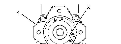
Illustration 7 g01333452
Typicalair compressorwith a SAE drive
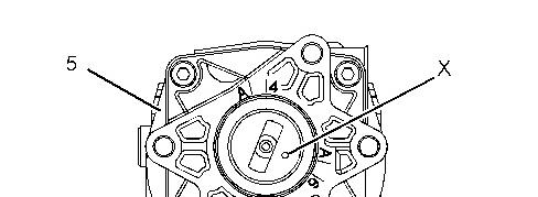
Illustration 8 g01333453
Typicalair compressorwith a DIN drive
5. Rotate the crankshaft of the air compressor until timing Mark (X) is aligned with timing mark A6 on the rear face of air compressor (5). Refer to Illustration 7 for air compressors with a SAE drive. Refer to Illustration 8 for air compressors with a DIN drive.
Illustration 9 g01353470
Typicalexample
6. Align air compressor (5) with studs (13). Install the air compressor to the front housing. If necessary, rotate the crankshaft of the air compressor in a clockwise direction in order to align the gears.
Note: Ensure that timing Mark (X) is aligned with the timing mark A6. Refer to Illustration 7 for air compressors with a SAE drive. Refer to Illustration 8 for air compressorswith a DIN drive.
7. Install nuts(14). Tighten the nutsto a torque of 78 N·m (58 lb ft).
8. If necessary, followSteps8.a through 8.c in order to install cover (15).
a. Install a new O-ring seal (12) to cover (15). Use Tooling (E) in order to lubricate the O-ring seal.
b. Install cover (15) to air compressor (5).
c. Install bolts (16). Tighten the bolts to a torque of 13 N·m (9.5 lb ft).
Illustration 10 g01353469
Typicalexample
9. Position support bracket (10) onto air compressor (5). Install bolts (9) finger tight.
10. Install bolts (11) finger tight.
11. Tighten bolts (9) to a torque of 9 N·m (80 lb in).
12. Tighten bolts (11) to a torque 44 N·m (32 lb ft).
13. Loosen bolts (9) in order to allow air compressor (5) to return to the air compressor natural position.
14. Tighten bolts (9) to a torque of 22 N·m (195 lb in).
Note: Ensure that the air compressor isnot stressed as the bolts are tightened.
15. Install tube assembly (8) to air compressor (5) and to the cylinder block. Tighten the nutsto a torque of 9 N·m (80 lb in).
16. Remove Tooling (B) from Hole (X) in the cylinder block. Install plug (1) to the cylinder block. Refer to Illustration 6.
17. If the engine is equipped with a hydraulic pump on the rear of the air compressor, install the hydraulic pump. Refer to the OEMfor the correct procedure.
18. Connect the air linesto ports (4) and (6) in the air compressor. Refer to the OEMfor the correct procedure.
19. Connect coolant hoses(2) and (3) to air compressor (5).
20. Fill the cooling system with coolant to the correct level. Refer to Operation and Maintenance Manual.
Copyright 1993 - 2021 Caterpillar Inc. All Rights Reserved. Private Network For SIS Licensees. Sat Apr 24 21:21:21 UTC+0530 2021
Product: WHEEL LOADER
Model: 938H WHEEL LOADER LKM
Configuration: 938H Wheel Loader LKM00001-UP (MACHINE) POWERED BY C6.6 Engine
Disassembly and Assembly
C6.6 Engines for Caterpillar Built Machines
Media Number -KENR6081-15
Updated -04/03/2014
Alternator - Install - Alternators with Mounting Lugs
SMCS - 1405-012
Installation Procedure NOTICE
Keep all partsclean from contaminants.
Contaminants may cause rapid wear and shortenedcomponent life.
i02786955
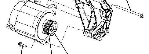
Illustration 1 g01334584
Typicalexample
1. If necessary, install pulley (7) and nut (8) to alternator (3). Hold the shaft of alternator (3) with an allen wrench. Use a cranked ring spanner in order to tighten nut (8).
Note: Different types of alternator have different sizes of nut. Ensure that the correct torque value is used for the nut.
Tighten M16 and M17 nutsto a torque of 80 N·m (59 lb ft). Tighten 5/8 inch - 18 UNF nuts to a torque of 102 N·m (75 lb ft).
2. Position alternator (3) on alternator mounting bracket (4).
3. Install bolt (5) to alternator (3). Install washer (2) and nut (1) to bolt (5).
4. Install bolt (6) to alternator (3).
5. Tighten nut (1) and bolt (6) to a torque of 22 N·m (16 lb ft).
6. Connect wiring harness assembly to alternator (3).
7. Install the alternator belt. Refer to Disassembly and Assembly, "Alternator Belt - Remove and Install".
8. Turn the battery disconnect switch to the ON position.
Product: WHEEL LOADER
Model: 938H WHEEL LOADER LKM
Configuration: 938H Wheel Loader LKM00001-UP (MACHINE) POWERED BY C6.6 Engine
Disassembly and Assembly
C6.6 Engines for Caterpillar Built Machines
Media Number -KENR6081-15
Updated -04/03/2014
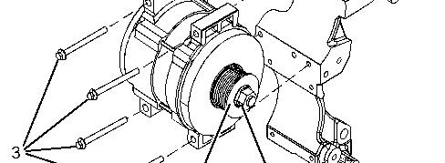
Alternator - Install - Alternators with Mounting Pads
SMCS - 1405-012
Installation Procedure
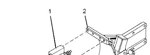
Illustration 1 g01334617
i02786954
1. If necessary, install pulley (4) and nut (5) to alternator (1). Hold the shaft of alternator (1) with an allen wrench. Use a cranked ring spanner in order to tighten nut (5). Tighten the nut to a torque of 127 N·m (93 lb ft).
2. Position alternator (1) on alternator mounting bracket (2). Install bolts(3) into the alternator bracket. Tighten the bolts to a torque of 44 N·m (32 lb ft).
3. Connect the wiring harnessassembly to alternator (1).
4. Install the alternator belt. Refer to Disassembly and Assembly , "Alternator Belt - Remove and Install".
5. Turn the battery disconnect switch to the ON position.
Copyright 1993 - 2021 Caterpillar Inc. All Rights Reserved. Private Network For SIS Licensees. Sat Apr 24 21:20:19 UTC+0530 2021
This is the sample of the manual click on the download link for complete manual
Product: WHEEL LOADER
Model: 938H WHEEL LOADER LKM
Configuration: 938H Wheel Loader LKM00001-UP (MACHINE) POWERED BY C6.6 Engine
Disassembly and Assembly
C6.6 Engines for Caterpillar Built Machines
Media Number -KENR6081-15
-04/03/2014
Alternator - Remove - Alternators with Mounting Lugs
SMCS - 1405-011
Removal Procedure
Start By:
a. Remove the alternator belt. Refer to Disassembly and Assembly, "Alternator Belt - Remove and Install" for the correct procedure.
NOTICE
Keep all partsclean from contaminants.
Contaminants may cause rapid wear and shortenedcomponent life.
1. Turn the battery disconnect switch to the OFFposition.
2. Place identification marks on all of the wiring harness connections.
i05735344