Product: TRACK LOADER
Model: 931C II TRACK LOADER 6AJ
Configuration: 931C & 931C LGP SERIES II TRACK LOADER / POWER SHIFT / 6AJ00001-UP (MACHINE) POWERED BY 3204 ENGINE
Disassembly and Assembly
D3B & 931B BACKHOE
Media Number -SENR2593-00
Hydraulic Oil Cooler
SMCS
Publication Date -01/12/1981
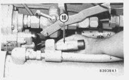
Remove And Install Hydraulic Oil Cooler
Date Updated -11/10/2001
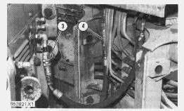
Lower all hydraulically controlled equipment to the ground. Slowly remove the hydraulic tank filler cap to release pressure in the hydraulic tank. This will prevent the sudden release of hot hydraulic oil which can cause personal injury.
4.
6.
Product: TRACK LOADER
Model: 931C II TRACK LOADER 6AJ
Configuration: 931C & 931C LGP SERIES II TRACK LOADER / POWER SHIFT / 6AJ00001-UP (MACHINE) POWERED BY 3204 ENGINE
Disassembly and Assembly
D3B & 931B BACKHOE
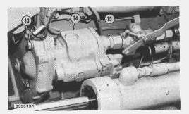
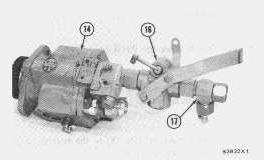
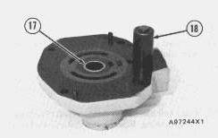
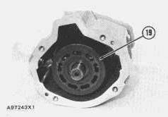
Piston Hydraulic Pump
Remove
This is the sample of the manual
Click on the download link for complete Manual
6.
NOTE:
7.
8.
9.
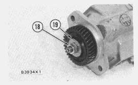
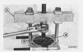
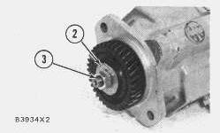
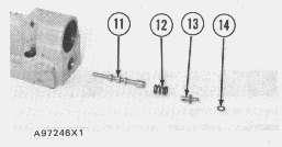
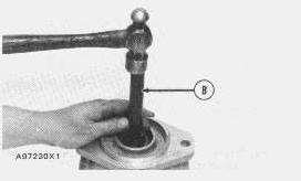
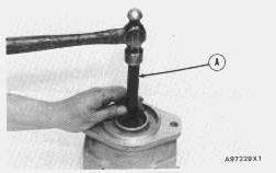
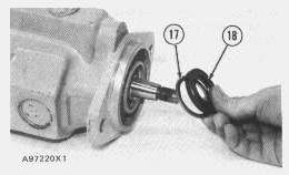
Do not remove gear (20) with tooling (A) unless nut (18) is installed.
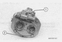
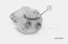
Piston Hydraulic Pump
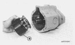
5.
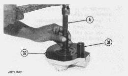
6.
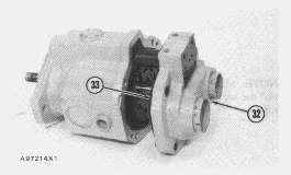
7.
NOTE:
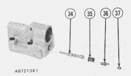
8.
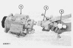
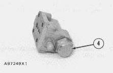
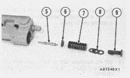
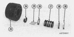
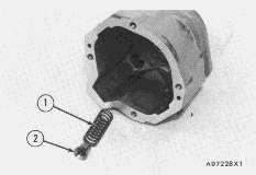
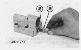
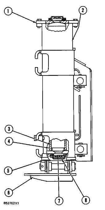
There is spring force behind cap (4).
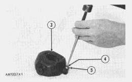
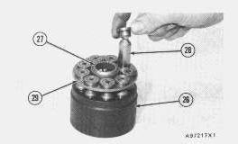
Be extra careful not to cause damage to the machined (highly finished) surface on the plate assembly and barrel assembly.
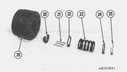
There is spring force behind snap ring (29). 12.
19.
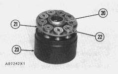
Assemble Piston Hydraulic Pump
9.
NOTICE
Be extra careful not to cause damage to the machined (highly finished) surfaces of the barrel assembly.
15.
NOTICE
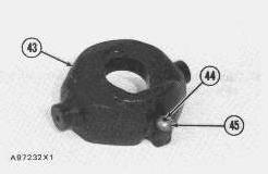
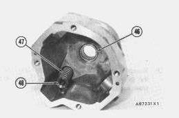
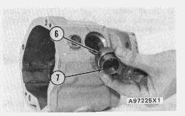
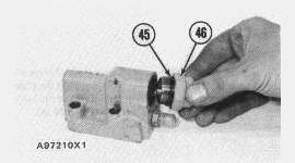
Pins (21) must be installed in the special grooves in the barrel.
16.
NOTICE
Be extra careful not to cause damage to the machined (highly polished) surface of the plate assembly.
Product: TRACK LOADER
Model: 931C II TRACK LOADER 6AJ
Configuration: 931C & 931C LGP SERIES II TRACK LOADER / POWER SHIFT / 6AJ00001-UP (MACHINE) POWERED BY 3204 ENGINE
Disassembly and Assembly
D3B & 931B BACKHOE
Media Number -SENR2593-00 Publication Date -01/12/1981 Date Updated -11/10/2001
Backhoe frame (Sideshift)
SMCS
Remove Backhoe Frame
4.
5.
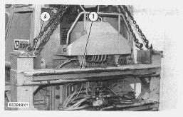
NOTICE
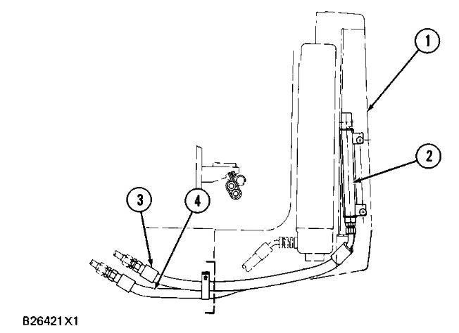
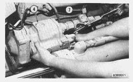
Do not start the machine with hose assemblies (3) and (4) disconnected. Connect the fitting on hose assembly (4) to the fitting on the machine for hose assembly (3) before the machine is started. Failure to do this can cause damage to the hydraulic system.
Install Backhoe Frame
1.
2.
This is the sample of the manual
Click on the download link for complete Manual
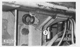
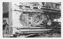
If the backhoe frame is to be put in a horizontal position, give support to the stabilizer cylinder rod at the bottom of the backhoe frame. Failure to do so will cause distortion of plate (1).
6.
NOTE:
7.
8.