"Queue
Status Screen" Information
Queue Information System Description
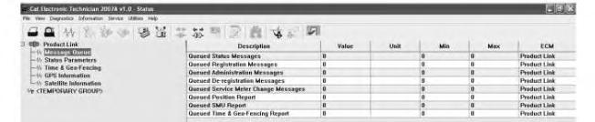
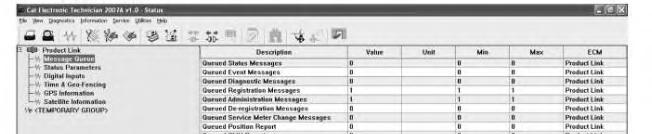
Queued Status Messages
Queued Event Messages
Queued Diagnostic Messages
Queued Registration Messages
Queued Administration Messages
Queued DeRegistration Messages
Queued Service Meter ChangeMessages
Queued Position Report
Queued SMU Report
Queued FuelReport
Queued Time and GeoFencing Report
Queued ECM List Report
PL121SR and PL321SR
PL321SR
PL321SR
PL121SR and PL321SR
PL121SR and PL321SR
PL121SR and PL321SR
PL121SR and PL321SR
PL121SR and PL321SR
PL121SR and PL321SR
PL321SR
PL121SR and PL321SR
PL321SR
This valueis the current count of status messages thatare pending to be sent by the Product Link module. This number can beup to 3.
This valueis the current count of eventmessages that are pending to be sent by the Product Link module. This number can beup to 5.
This valueis the current count of diagnostic messages that are pending to be sent by the Product Link module. This number can beup to 5.
This valueis the current count of registration messages that are pending to besent by the Product Link module. This number is either 0 or 1.
This valueis the current count of administration messages thatare pending to be sent by the Product Link module. This number is either 0 or 1.
This valueis the current count of de-registration messages thatare pending to be sent by the Product Link module. This number is either 0 or 1.
This valueis the current count of hour change messages for the servicemeter that are pending to be sent by theProduct Link module. This number can be up to 5.
This valueis the current count of position report messages thatare pending to be sent by the Product Link module. This number is either 0 or 1.
This valueis the current count of report messages for the service meter unit that are pending to be sent by the Product Link module. This number is either 0 or1.
This valueis the current count of fuel reports thatare pending to be sent by theProductLink module. This number is either 0 or 1.
This valueis the current count of "Timeand Geo-Fencing Report" messages that arepending to be sent by the Product Link module. This number can be up to 3.
This valueis the current count of ECM list reports thatare "pending to be sent" by the Product Link module. This number can be up to 5.
Test messages can beadded to thequeues by selecting "PLMCommands" from the"Service" drop-down menu. Then, the user must select the desired message. Allpending messages can becleared by selecting "Clear Message Queue" from this menu.
Note: Do not clear out eventmessages (legitimate) or diagnostic messages that need sent. Messages will not be created again unless an event or a diagnostic occurs again.
Illustration 8
View of "Message Buffer" Screen
If themessage buffer is full, Cat ET willdisplay a message of "Unable to send the PLM Command. The command was denied because themessage buffer is full.". Refer to Illustration 8.
"Message Buffer Full" - If Cat ET is showing a message thatis still in the queue, the user must wait up to 15 minutes before queueing an additional message of the same type. If theuser attempts to queuean additional message of thesame typeprior to the15 minuteperiod, the"MessageBuffer Full" message will display.
"Message Timer Not Expired" - If CatET is not showing amessage in thequeue,theuser must waitup to 15 minutes before queueing an additional messageof thesame type. If the user attempt to queuean additional message of thesame typeprior to the15 minuteperiod, the"MessageTimer NotExpired" message may display.
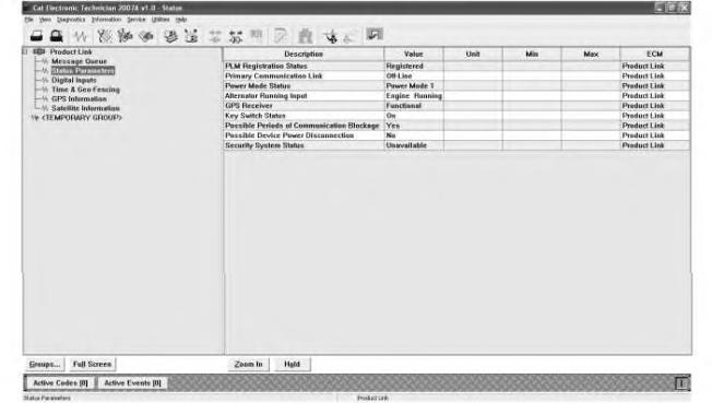
"PLM Operational Status" Screen
The Product Link "Status parameters" screens in Illustration 9 and Illustration 10 showthe current operationalstatus of the Product Link module.
Device Configuration and Status Screen for PL121SR
Illustration 10
Device Configuration and Status Screen PL321SR
Refer to Table 2 for an explanation of the PLM parameters.
Table 2
Device Configuration and Status Information for Product Link
Product Link Information System Description
PLMRegistration Status
Primary Communication Link
Power ModeStatus
PL121SR and PL321SR
PL121SR and PL321SR
PL121SR and PL321SR
g01363208
Registered: The PLMis properly registered on the communications system. The PLMmust be registered for messages to be transmitted.
De-registered: The PLMis notregistered on the communications system and will not transmit any messages except aregistration command.
Confirmation Pending: The PLM is awaiting confirmation that the registration was successfully processed in the back office. Failed: ThePLM registration was not processed successfully. Verify that theparameters are correct.
On Line:A communications satellite is in view allowing the PLM to send and receive messages.
Off Line: There are no communications satellites in viewso no messages can be transmitted.
Power Mode 1: The machine has operated in the last 48 hours. If thekey is OFF, The PL121 will check for messages and wake up the PL300 as needed (if installed).
Power Mode 2: The machine has not operated for atleast48 hours, but themachinehas operated in thelast 7 days. The PLM willwake up periodically (every 6 hours by default) to send and receivemessages.
Alternator Running Input
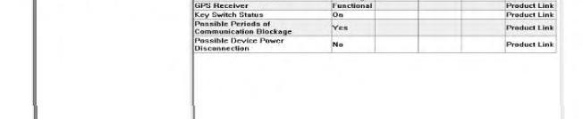
GPS Receiver
Status of the Keyswitch
PL121SR and PL321SR
PL121SR and PL321SR
PL121SR and PL321SR
Power Mode 3: The machine has not operated In thelastseven days. The PLMwill wakeup every 24 hours to send and receive messages. All modules with the latest softwareare in Power Mode 3 until initialregistration.
PL121 and PL321"operation" refers to Engine running.
Engine Running: The Alternator R-Terminal reflects that the engineis currently running.
Engine Off: TheAlternator R-Terminal reflects that theengine is not currently running.
Functional: The hardware for the GPS receiver is functional. NotFunctional:Thehardwarefor the GPS receiver is not functional.
On:Themachinekeyswitch is in the ONstate.The PLM will bepowered up.
Off: Themachinekeyswitch is in the OFF state.ThePLM will periodically power up in order to send messages and receive messages depending on thePower Mode.
Possible Periods of Communication Blockage
PL121SR and PL321SR
Possible Device Power Disconnection
Status of the Security System
PL121SR and PL321SR
PL321SR
Yes: The PLMhas not seen a communications satellite for an extended period of time causing scheduled reports to bemissed. This value is reset automatically after the status is reported to the office.
No:ThePLM has not experienced a loss of communications and has been communicating as scheduled.
Yes: The PLMhas missed reports dueto apower loss. This value is resetautomatically after the status is reported to the office.
No:ThePLM has not missed any scheduled reports dueto power loss.
Available: MSS is detected Unavailable: MSS is not detected
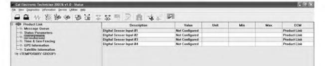
Illustration 11 g01363225 "Digital Inputs" Screen
The digital sensor information is shown in "Digital Inputs". Refer to Illustration 11. Refer to Table3 for an explanation of related parameters for the digital sensor.
Table 3
Configurationand Status Information forthe Digital Sensor
Digital Sensor System Description
DigitalSensor Input #1 PL321SR
DigitalSensor Input #2 PL321SR
DigitalSensor Input #3 PL321SR
DigitalSensor Input #4 PL321SR
Active: The switch is operating outside of normal conditions. Not Active:Theswitch is operating within normalconditions. Not Configured: Theswitch has not been configured or installed.
Active: The switch is operating outside of normal conditions. Not Active:Theswitch is operating within normalconditions. Not Configured: Theswitch has not been configured or installed.
Active: The switch is operating outside of normal conditions. Not Active:Theswitch is operating within normalconditions. Not Configured: Theswitch has not been configured or installed.
Active: The switch is operating outside of normal conditions. Not Active:Theswitch is operating within normalconditions. Not Configured: Theswitch has not been configured or installed.
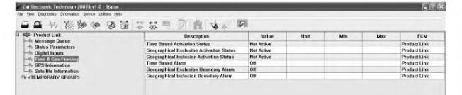
Illustration 12 g01364433 "Time and Geo-Fencing" Screen
The Product Link "Timeand Geo-Fencing" screen that is shown in Illustration 12 shows the current status of the "Fence" parameters. "Fencing" allows tracking of themovement of amachine. There are three types of "Fences" that are available:
"Geographic Exclusion" - When active,the option "GeographicExclusion" of "Fencing" will generate a report if a machinemoves into an unknown area.
"Geographic Inclusion" - When active, the"Geographic Inclusion" option of "Fencing" willgenerate a report if a machinemoves out of aspecified area.
"Time Based" - If a machine is operated outsideof a specified time period, the "Fencing" option will generate a report.
Refer to Table 4 for an explanation of the Fenceparameters.
Table 4
FenceStatus GroupParameters
Status Values
Active
Time Based Activation Status
Geographical Exclusion Activation Status
Geographical Inclusion Activation Status
Not Active
Active
Not Active
Active
Description
Time Based ProductWatch has been properly configured and is currently activated.
There is currently no Time Based ProductWatch properly configured and/or it is not currently activated.
Geographical Exclusion Product Watch has been properly configured and is currently activated.
There is currently no Geographical Exclusion Product Watch properly configured and/or it is not currently activated.
Geographical Inclusion Product Watch has been properly configured and is currently activated.
Time Based Alarm
Geographical Exclusion Boundary Alarm
Geographical Inclusion Boundary Alarm
Not Active
There is currently no Geographical Inclusion Product Watch properly configured and/or it is not currently activated.
On There is an activeTime Based Alarm.
Off There is not an activeTimeBased Alarm.
On There is an activeGeographical Exclusion Boundary Alarm.
Off There is not an activeGeographical Exclusion Boundary Alarm.
On There is an activeGeographical Inclusion Boundary Alarm.
Off
"GPS Information" Status
There is not an activeGeographical Inclusion Boundary Alarm.
13
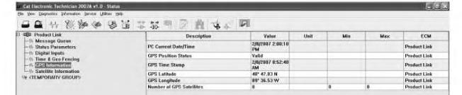
g01363341 "GPS Information" Screen
The Product Link PL121SR "GPS Information" screen shown in Illustration 13 shows thecurrent status of the ProductLink GPS. Refer to Table5 for an explanation of the GPS-related parameters.
Table 5
GPS InformationParameters
Status
Description
PC Current Date/Time The current Date and Time of the hostPC is displayed.
GPS Position Status Valid: The Product Link Module has previously calculated a valid fix. Invalid: The Product Link Modulehas not calculated a previous fix.
Illustration
GPS Time Stamp The time stamp from the last fix is displayed. The time can becompared to the Current Date/Time to verify that the time since thelast position was calculated.
GPS Latitude The last valid GPS Latitude is displayed.
GPS Longitude The last valid GPS Longitude is displayed.
Number of GPS Satellites The number of GPS satellites currently in use by the GPS receiver.(1) (1) Three or more satellites are needed to get an updated position fix.
"Satellite Information" Status
14
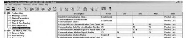
Satellite Information Screen
Note: Disregard the value of the "Average Wireless Communication Error Count" when satellite communication status value equals "Not Established". To havea "Average Wireless Communication Error Count" is normal,if communication with the satellite is not established.
The "SatelliteInformation" screen for the Product Link PL121SR that is shown in Illustration 14 shows the current satellite communications status. Refer to Table 6 for an explanation of satellitecommunications status parameters.
Table 6
Satellite Communications Status Information Communications Status Information System Description Notes
Satellite Communication Status PL121SR and PL321SR
Established: The PLM has an active connection to a satellite.
Illustration
g01450732
Satellite Network ControlCenter Communication Status
PL121SR and PL321SR
Not Established:ThePLM does not have an activeconnection to a satellite.
Average Wireless Communication Error Count
PL121SR and PL321SR
Established: The satellite thatthe PLM is communicating with has a connection to a Network Control Center (ground station).
Not Established:Thesatellitethat the PLMis communicating with does not have a connection to a Network Control Center (ground station).
This valueis an indication of the quality of the connection with the satellite used fortroubleshooting satellite connections. The lower the number, with a minimum of 0, the better the signal strength. As the value increases, the amount of transmittime for signals increases.
This is not an error mode. Satellites move quickly. Often times a satellite has moved out of view of the antennaand another has not yet moved into view of the antenna.
Communications Satellite Identification Number
Communications Modem Signal to Noise Ratio
PL121SR and PL321SR
This valueidentifies the particular communications satellitethat the PLM is tracking.
This is not an error mode. Satellites move quickly. Often times a satellite has moved out of view of the antennaand another has not yet moved into view of the antenna.
Communications Modem Signal Quality
Communications Modem Status
PL121SR and PL321SR
PL121SR and PL321SR
PL121SR and PL321SR
Communications Modem Activation Delay Time
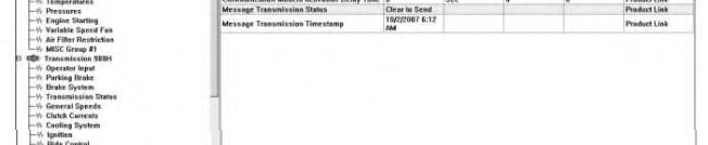
Message Transmission Status
This valueindicates quality of the communications signal expressed as a number. Thehigher thenumber, the better the signal.
This valueindicates the overall quality of the communications signal based on several factors expressed as a percentage.
This valueindicates the provisioning status of the communications modem.
If no satelliteis in range, the indication will be "Conditions not met".
A value below10 will typically cause no transmissions. The higher the valueabove10, the better thechances of successfulmessage transmission.
0% = poor quality 100% = Best quality
Normal status is enabled. If status is "Disabled" or "Pending",contact your Caterpillar Technical Communicator.
PL121SR and PL321SR
This valueindicates the time thatthe communications modem has remaining in a "pending" status.
Displayed in h/m/s format.
Indications are:No Message in Queue
PL121SR and PL321SR
This status indicates wherethe queued messagelies in its transmission cycle.
Message Transmission Timestamp PL121SR and PL321SR
This is an indication to showthe exactdate and time that thelast message was successfully transmitted to thecommunications satellite.
Ready to send Clear to send Sending Sent Requeuing
Displayed in number format date/timewith an AM/PM suffix. Copyright 1993 - 2020 Caterpillar Inc. All Rights Reserved. Private Network For SIS Licensees. Fri Aug 21 11:22:19 UTC+0530 2020
Product: TRACK LOADER
Model: 931C TRACK LOADER 6RF
Configuration: 931C & 931C LGP TRASH LOADERS 6RF00001-UP (MACHINE) POWERED BY 3204 ENGINE
Troubleshooting
Product Link 121S/300
Media Number -RENR7911-13 Publication Date -01/10/2014 Date Updated -19/09/2016
Diagnostic Code List
SMCS - 7569
Table 1
Module Identifier 122 Diagnostic Codes(1)
CID 0168 Electrical System
FMI 03 for PLVIMSand PL GSM Voltage above normal
FMI 04 for PLVIMSand PL GSM Voltage below normal
CID0254 Electronic Control Module
FMI 04
i05662649
Voltage below normal
FMI 12 Failed Module
CID 0269 Sensor Power Supply
FMI 03
FMI 04
FMI 09
FMI 03
Voltage above normal
Voltage below normal
CID 1250 Remote Communication Module
Unable to establish communication
CID 1251 Alternator R-Terminal
Voltage above normal
(1) For troubleshooting, see the procedure with the sameCID FMI.
Note: A machine ECM will self-erase a diagnostic if the diagnostic doesnot reappear after 100 operating hours. When thisevent happens, the event history screen in the EquipmentManager application will show a code that occurred 100 hours in the past that no longer showsup in Cat ET because the diagnostic has not reoccurred.
Product: TRACK LOADER
Model: 931C TRACK LOADER 6RF
Configuration: 931C & 931C LGP TRASH LOADERS 6RF00001-UP (MACHINE) POWERED BY 3204 ENGINE
Troubleshooting
Product Link 121S/300
Media Number -RENR7911-13
Diagnostics and Events Not Available
SMCS - 0785-038-UE; 7610-038
System Operation Description:
i05662620
There are problems that could be reported with the Product Link system but the problems are not caused by the Product Link system. The problem can be described as the diagnostic information or events are not received at the office. Thissection containsstepsthat are used to determine the possible cause. Check for active diagnostic codes for the Product Link. Correct any diagnostic codes before proceeding. The following items should be visually inspected for damage: PL121SR radio, PL300 module, antenna and cables. Verify that there are no loose connections.
The Product Link system depends on several communication links in order to transfer data from the machine to the office. The following procedures assume that these communication links are operating properly. The proper communication linksare listed below:
• The satellite network for VHF communications is operational in the geographic area of concern. The network isoperational when messages can travel to the satellite and the messages can travel to the earth and Caterpillar.
• The Product Link system iscorrectly configured to communicate on the network for VHF communications.
• The worldwide network of Caterpillar's computers is passing messages to software of the Caterpillar Equipmentmanager (EM).
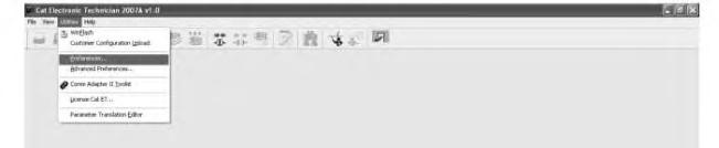
• The Caterpillar Electronic Technician (Cat ET) isconfigured properly and the software is functioning.
The PL121SR radio or the PL300 module should not be replaced without verifying that these issues have been investigated. Contact your Caterpillar Technical Communicator for aid in resolving these issues.
The Product Link can be configured in order to transmit diagnosticsand eventsto the office. These transmissions are highly dependent on the configuration of the Product Link. The following troubleshooting steps assume that the position and the Standard Report are being received.
Test Step 1. ACCESS THE PRODUCT LINK THROUGH THE CAT ET SERVICE TOOL.
A. Connect the Cat ET service tool to the machine.
B. Verify that the ECM(Product Link) isavailable.
Expected Result:
The ECM (Product Link) is available.
Results:
• OK - The ECM (Product Link) is available. Proceed to Test Step 2.
• NOT OK - The ECM (Product Link) is not present in the Cat ET screen.
Repair: Verify that the wiring for the Product Link has been installed correctly. Check the wiring with a multimeter. If the ECM ( Product Link) is not available, see Systems Operation, Troubleshooting, Testing and Adjusting, "Electronic Service Tool Does Not Communicate with ECM".
STOP
Test Step 2. VERIFY THAT THE PRODUCT LINK MODULE IS CONFIGURED PROPERLY.
A. Go to the "Configuration" screen. See SystemsOperation, Troubleshooting, Testing and Adjusting, "Installation Parameters Configure" for more information.
B. Verify that the "Warning Level 3 Report Configuration"isset to either "Immediate" or "Next Scheduled".
C. Verify that the "Warning Level 2 Report Configuration"isset to either "Immediate" or "Next Scheduled".
D. Verify that the "Warning Level 1 Report Configuration"isset to either "Immediate" or "Next Scheduled".
E. Verify that the "Diagnostic Report Configuration" isset to either "Immediate" or "Next Scheduled".
Expected Result:
All settings are correct.
Results:
• OK - The Product Link is configured correctly. Proceed to Test Step 3.
• NOT OK - The Product Link is not configured correctly.
Repair: Configure the Product Link again. Refer to Systems Operation, Troubleshooting, Testing and Adjusting, "Installation ParametersConfigure".
STOP
Test Step 3. CHECK FORLOGGED EVENTS OR DIAGNOSTICS THAT MAY HAVE OCCURRED.
Use the Cat ET service tool in order to verify the existence of logged events or diagnostics on other ECM systems to report to the office. Note any eventsand diagnostics that are not reported.
Expected Result:
There are no logged eventsor diagnostics that should have been reported.
Results:
• OK - There are no logged events or diagnostics that should have been reported. The Product Link appears to be working correctly.
STOP
• NOT OK - There are logged events or diagnostics that should have been reported. Monitor the operation of the Product Link for reporting of events and diagnostics. Problems in this area are not usually a problem with the module. Ensure that the "Event/Diagnostic Report Interval (SMU)" and the "Event/Diagnostic Message Interval (RT)" are configured properly. Ensure that the module isreporting as expected based on those settings. The module should not be replaced.
STOP Copyright 1993 - 2020 Caterpillar Inc. All Rights Reserved. Private Network For SIS Licensees. Fri Aug 21 11:24:24 UTC+0530 2020
Product: TRACK LOADER
Model: 931C TRACK LOADER 6RF
Configuration: 931C & 931C LGP TRASH LOADERS 6RF00001-UP (MACHINE) POWERED BY 3204 ENGINE
Troubleshooting
Product Link 121S/300
Media Number -RENR7911-13
ECM Does Not Communicate with User Interface
SMCS - 7606-038-EK2
Test Step 1. Off-Site Diagnostics.
Note: Some steps of the "Off-Site Diagnostics" sections are dependent on the customer being on site.
A. Determine the Subscription Status
Check the status of the customersProduct Link subscription within the "Trimble VisionLink Store".
a. If the subscription status is not current, refer to Step 2. Product Link Subscription Status is Not Current.
b. If the subscription status is current, refer to Step 3. Product Link Subscription Status isCurrent.
B. Product Link Subscription Status is Not Current
Check to see if the subscription isset up correctly, or isout of date. Contact your dealer administrator for subscription services.
C. Product Link Subscription Status is Current
a. Log on to the equipment page through Vision Link.
i06045349
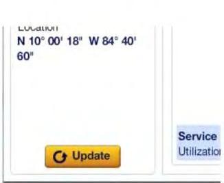
Illustration 1 g03773257
Refresh buttonshownwitharrow.
b. On the equipment page click on the refresh button.
- If the equipment checksin with new data, then the equipment was more than likely out of coverage. The equipment should continue to check in from this point as long as coverage remains available.
- If the equipment does not respond to the "Refresh", continue to Step c.
Do not operate or workon this equipment unless youhave read and understand the instructions and warningsin the Operation and Maintenance Manuals. Failure to followthe instructions or heed the warnings could result in injury or death. Contact your Caterpillar dealer for replacement manuals. Proper care is your responsibility.
c. Request the location of the equipment. With the customer at the location of the equipment, the following questions may or may not be answered. Ask the customer if the equipment is powered ON, and located where the radios have clear line of sight to the sky.
- If the equipment wasinside of a building, under/next to a large obstacle, or has the battery power OFF, have the customer do the following:
Turn the equipment power ONif the power was OFF.
Attempt to move the equipment to a more open location with a clear line of sight to the sky.
Results:
Try the "Refresh" again.
- If the equipment wasON and in a good location for data transfer, have the customer check to see if the equipment has a radio disable switch installed. If the equipment has a radio disable switch, have the customer check to see if the radio disable switch was disabled.
• Off-Site diagnostics were performed prior to sending a tech on site to troubleshoot the Product Link Not Communicating problem and the Vision Link "Refresh Button" does not return new data, continue to "Test Step 2. CHECK THE INSTALLATION OF THE ANTENNA"STOP
Test Step 2. CHECK THE INSTALLATIONOF THE ANTENNA.
Observe installation of the antenna for the Product Link. Verify that the antenna is installed with a clear view of the sky. The Product Link antenna and coaxial cable must be in a location that is not close to radio frequency interference (RFI). Examplesof interference may include but are not limited to include the following items:
• Product Link radio antenna located too close to sources of radio frequency interference (RFI) such as:
- Rotating Beacon lights, Halogen Strobe lights, and AC Fans. Refer to Special Instruction, REHS2365, "Installation Guide for Product Link PL121SR and PL321", "Interference from Warning Beacons". Also Refer to Service Magazine, SEPD1639, "Product Link Signal Communication Improvements Are NowAvailable on Certain Large Wheel Loaders, Landfill Wheeled Dozers, and Landfill Compactors" which addressesadequate shielding to prevent radio interference with Product Link antenna.
- LED lightsare recommended. Refer to Service Magazine, SEPD1908, "Revision to "Reports and Messages Not Available" Troubleshooting Procedure for Cat® Productswith Cat® Product Link 121/321" for the recommended LED lights.
- Other communication antennason the roof of the machine.
Refer to Special Instruction, REHS2365, "Installation Guide for Product Link PL121SR and PL321" for additional details on optimal installation of the antenna.
- Tie-wrap tightness on coax hold-downsshould be snug enough to limit rubbing but not overtightened to prevent crushing or pinching of the coax shielding.
- Coax should be located a minimum of 9 mm (0.35 inch) from any Control module.
- Last coax tie-wrapsshould secure within 175 mm (6.89 inch) of the coax connector.
Expected Result:
The antenna isinstalled properly according to the guidelines and specifications listed in this procedure and Referenced publications.
Results:
• OK - The antenna for the Product Link is installed properly. Verify that all of the connections for the antenna are tight. Proceed to Test Step 3.
• NOT OK - The installation of the antenna is not optimal.
Repair: Reinstall the antenna at a superior location.
STOP
Test Step 3. ACCESS THE PRODUCT LINK THROUGH CATERPILLAR ELECTRONIC TECHNICIAN(CAT ET).
A. Connect Cat ET to the machine.
B. Verify that the ECM(Product Link) isavailable.
Expected Result:
The ECM (Product Link) is available.
Results:
• OK - The ECM (Product Link) is available. Proceed to "Test Step 5. VERIFYPRODUCT LINK SETTINGS AND CONFIGURATIONS ARE CORRECT.".
• NOT OK - The ECM (Product Link) is not present in the Cat ET screen. Proceed to Test Step 4. VERIFY THE PRODUCT LINK WIRING.
Test Step 4. VERIFY THE PRODUCT LINK WIRING.
Note: Ensure the Master Disconnect is closed and the Key Switch is ON.
• Check for a blown fuse and replace if necessary.
• Check to see if there is an optional "Radio Disable Switch" installed. If there is a "Radio Disable Switch" installed, make sure that the switch is in the ONposition. Refer to Special Instruction, REHS2365, "Installation Guide for Product Link PL121SR and PL321Optional Installation of Product Link Blast Zone Switch" for more information
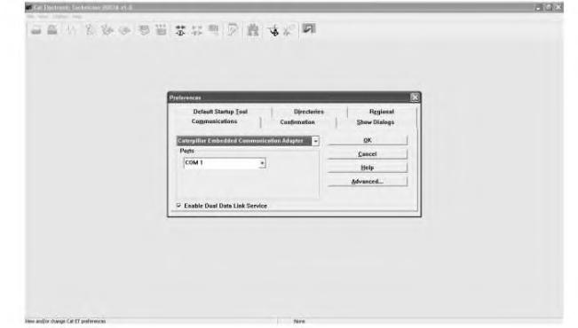
• Verify that the green LEDon the radio is ON. The green LED signifiesthat the radio is receiving system voltage and key switch power.
• If the LEDisnot visible, use a voltmeter to verify that the radio hassystem voltage on pin 1 (battery +) and switched power on pin 3 (key switch).
• For PL321 systems, verify that the PL300 hassystem voltage on pin 52 or 53 (battery +) and switched power on pin 70 (key switch).
• Verify the data link wiring from the Product Link to Cat ET, including any Communication Adapter being used.
Expected Result:
For PL121 systems, if all wiring is OK and the radio is receiving the proper power, replace the radio and verify that the replacement resolved the issue. Refer to section "Select a Location for Mounting the PL121SR Radio" to make sure that the radio ismounted optimally.
For PL321 systems, if all wiring is OK and the Product Link is receiving the proper power, replace the PL300 and verify that the replacement resolved the issue. Refer to section "Select a Location for the PL300 ECM" to make sure that the PL300 is mounted optimally.
Results:
• OK - All wiring is correct. PL121 and PL321 systemsare properly working.
• NOT OK - If any wiring discrepancieswere found, repair or correct the issue and verify that the issue was resolved.
STOP
Test Step 5. VERIFY PRODUCT LINK SETTINGS AND CONFIGURATIONS ARE CORRECT.
Reference: Special Instruction, REHS2365, "Installation Guide for Product Link PL121SR and PL321", "Configure and Register Product Link PL121SR Radio and PL300 ECM"
Reference: Special Instruction, REHS2365, "Installation Guide for Product Link PL121SR and PL321", "Review Product Link Device Configuration and Status"
A. Verify that the Product Link module hasbeen registered.
Verify that the "PLM Registration Status" is "Registered". Refer to Systems Operation, Troubleshooting, Testing and Adjusting, RENR7911, "Product Link 121S/300", "Diagnostic Capabilities" for an explanation of the "PLMRegistration Status".
Refer to Special Instruction, REHS2365, "Installation Guide for Product Link PL121SR and PL321", "Configure and Register Product Link PL121SR Radio and PL300 ECM".
B. Verify that the Product Link module isproperly configured.
Verify that the following configurationsare correct:
Dealer Code
"DBS Machine Make Code"
"Machine Serial Number"
"Maintenance Mode" is"Off"
"Global Gram Mode" setting iscorrect
Note: "Global Gram Mode" default setting is "disabled" and should not be changed for the majority of machines. Users should contact the DSN before enabling Global Gram Mode.
Results:
This is the sample of the manual
Click on the download link for complete Manual
• OK - Product Link settings listed above are correctly configured. Proceed to Test Step 6: VERIFY SATELLITE COMMUNICATIONS LINK
Test Step 6. VERIFY SATELLITE COMMUNICATIONSLINK.
In Cat ET, navigate to the Message Queue status screen and observe the number of queued messages. Take note of how many messages are pending in each message queue.
Each message queue has a maximum allowable number of messagesthat can be queued at the same time. In the most current production Product Link software, the maximum message count limits are:
• Status Messages: 10
• Event Messages: 5
• Diagnostic Messages: 5
• All other message types: 1
If any queue contains a number higher than the maximum listed above, replace the PL121 radio and retest.
In Cat ET, navigate to the Satellite Information statusscreen and monitor the varioussatellite parameters for a minimum of 15 minutes. Note the values shown in the following parameters:
• Average Wireless Communication Error Count
• Communication Satellite Identification Number
• CommunicationsModem Signal to Noise Ratio
• CommunicationsModem Signal Quality
Average Wireless CommunicationsError Count - An indication of the number of errors occurring in the communication traffic between the PL121 and the satellite. This number must be at or near zero in order for the Product Link to successfully transmit.
Communication Satellite Identification Number - The actual identification number of the satellite that the Product Link isattempting to communicate with.
Communications Modem Signal to Noise Ratio - A measure of the amount of noise in the communication signal between the PL121 and the satellite. The higher the number, the better the chancesare of the PL121 successfully transmitting a message. On average, a signal-to-noise level of 7.5 or higher is required to successfully transmit a message, although communications sometimes succeed with lower numbers.
Communications Modem Signal Quality - Ageneral indication of the quality of the communication link between the PL121 and the satellite. On average, a signal quality of 50% or higher is required to successfully transmit a message.
For PL121 Systems:
A. PL121 system with no messages in the queues.