

Product: TRACK LOADER
Model: 931B TRACK LOADER 25Y
Configuration: 931B TRACK LOADER / POWER SHIFT / 25Y00001-UP (MACHINE) POWERED BY 3204 ENGINE
Disassembly and Assembly
D3B & 931B BACKHOE
Media Number -SENR2593-00
Backhoe frame (Sideshift)
Publication Date -01/12/1981
Date Updated -11/10/2001
SMCS - 6510-17
Remove Backhoe Frame
start by:
a) remove swing frame and sliding frame
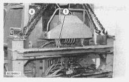
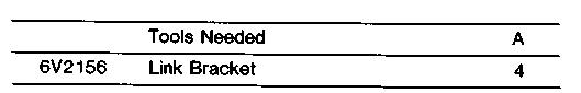
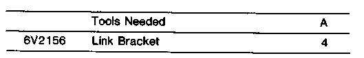
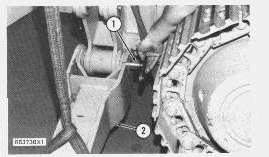
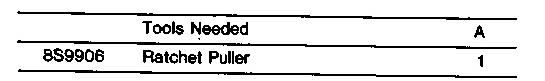
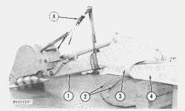
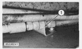
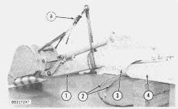
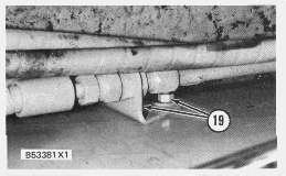
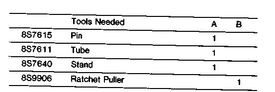
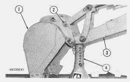
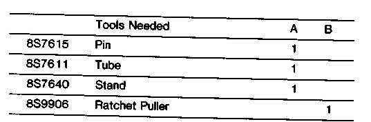
1. Fasten tooling (A) to the backhoe frame (1) and fasten a chain and hoist to tooling (A).
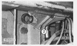
2. Remove pins (2) from each side of the backhoe frame.
3. Lift backhoe frame enough to disengage the lower pins with the brackets on the machine. The weight of the backhoe frame is 669 kg (1475 lb.)
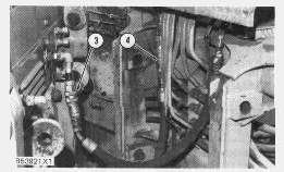
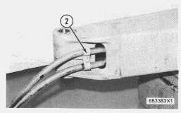
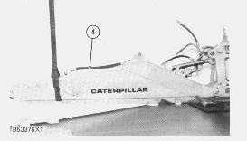
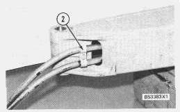
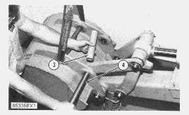
4. Move the backhoe frame to the rear enough to give access to hose assemblies (3) and (4).
5. Disconnect the hose assemblies (3) and (4) at the quick disconnect fittings.
NOTICE
Do not start the machine with hose assemblies (3) and (4) disconnected. Connect the fitting on hose assembly (4) to the fitting on the machine for hose assembly (3) before the machine is started. Failure to do this can cause damage to the hydraulic system.
Install Backhoe Frame
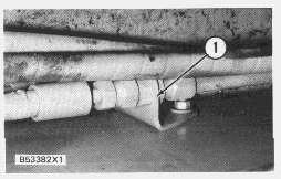
1. Fasten tooling (A) to the backhoe frame (2) asshown in REMOVE BACKHOE FRAME.
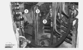
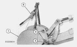
2. Put backhoe frame (2) in position to give access to hose assemblies (1) and (3).
3. Connect hose assemblies(1) and (3) at the quick disconnect fittings.
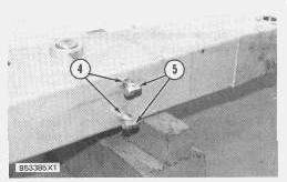
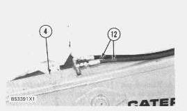
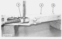
4. Engage the lower pinson backhoe frame (2) with the hooks in brackets(5).
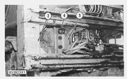
5. Make an alignment of the top hole for pin (4) in backhoe frame (2) and brackets (5) and install two pins (4), bolts and nuts.
end by:
1) install swing frame and sliding frame
Disassemble And Assemble Backhoe Frame
start by:
a) remove backhoe frame
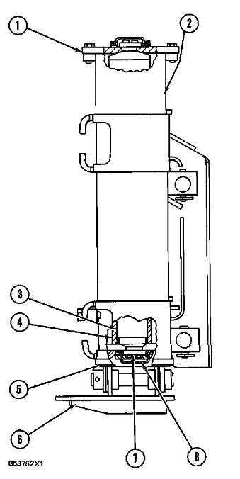
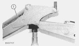
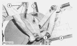
1. Put backhoe frame in vertical position on floor.
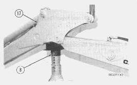
2. Remove cover (8) from the lower end of the tube assembly to be removed.
3. Remove three bolts and plate (7) from the tube assembly.
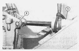
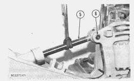
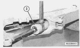
4. Carefully lift backhoe frame (2) clear of the tube assembly (5). Do not let the tube assembly fall as the backhoe frame isdisengaged from the tube assembly.
5. Lower backhoe frame (2) to the ground and give support to the frame in the vertical position.
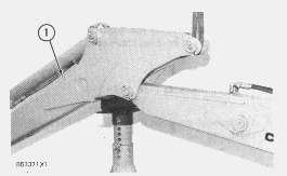
NOTICE
If the backhoe frame is to be put in a horizontal position, give support to the stabilizer cylinder rodat the bottom of the backhoe frame. Failure to do so will cause distortionof plate (1).
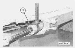
6. Lift backhoe frame (2) in a vertical position and engage with tube assembly (5).
NOTE: The short bosson pad (6) is toward the machine.
7. Engage cap (4) in tube assembly with cylinder rod (3).
8. Install plate (7) and bolts. Tighten bolts to a torque of 65 ± 5 N·m (48 ± 4 lb.ft.).
9. Install cover (8). end by:
a) install backhoe frame
Copyright 1993 - 2020 Caterpillar Inc. All Rights Reserved. Private Network For SIS Licensees. Wed Aug 26 10:37:22 UTC+0530 2020
This is the sample of the manual
Click on the download link for complete Manual
Product: TRACK LOADER
Model: 931B TRACK LOADER 25Y
Configuration: 931B TRACK LOADER / POWER SHIFT / 25Y00001-UP (MACHINE) POWERED BY 3204 ENGINE
Disassembly and Assembly
D3B & 931B BACKHOE
Media Number -SENR2593-00
Backhoe Stabilizer
SMCS - 6505-11; 6505-12
Publication Date -01/12/1981
Remove Backhoe Stabilizer
start by:
a) remove stabilizer cylinder
Date Updated -11/10/2001
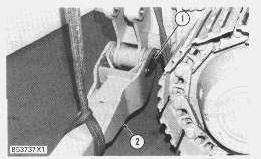
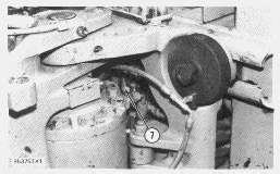
1. Fasten a hoist to the stabilizer. Remove pin (1) and remove stabilizer (2). The weight of stabilizer (2) is72 kg (160 lb.).
Install Backhoe Stabilizer
1. Put stabilizer (2) in position and install pin (1).
2. Install the spacer, bolt and washer to hold pin (1) in position.
end by:
a) install stabilizer cylinder
Aug 26 10:35:31 UTC+0530 2020
Product: TRACK LOADER
Model: 931B TRACK LOADER 25Y
Configuration: 931B TRACK LOADER / POWER SHIFT / 25Y00001-UP (MACHINE) POWERED BY 3204 ENGINE
Disassembly and Assembly
D3B & 931B BACKHOE
Media Number -SENR2593-00
Publication Date -01/12/1981
Boom And Boom Cylinder (SS)
SMCS - 5456-11; 5456-12; 6501
Remove Boom And Boom Cylinder
start by:
a) remove hoe stick cylinder
Date Updated -11/10/2001
1. Fasten a nylon strap and hoist to hoe stick (1). Lift the hoe stick enough to let the support stand be removed.
2. Lower the boom on to blocks.
NOTE: Move the control valve to the "LOWER" position during this procedure.
3. Pull bucket cylinder hydraulic hoses (2) out of hoe stick (1).
4. Put a nylon strap around the hoe stick and fasten the strap to a hoist. Fasten a nylon strap to the bucket and fasten tooling (A) to a hoist.
5. Remove pin (3) and remove the bucket and stick as an assembly away from boom (4). The weight is 415 kg (915 lb.).
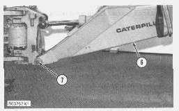
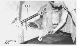
6. Fasten a nylon strap to boom hydraulic cylinder (5).
7. Remove pin (6) and lower the rod on to a wood block.
8. Put marks of identification for six hose connections (7).
9. Disconnect hose assemblies(7) and move the hose assemblies through the opening in the swing frame.

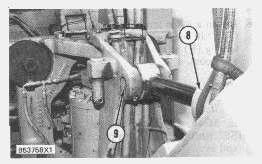
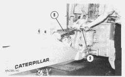
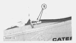
9. Remove bracket assembly (8).
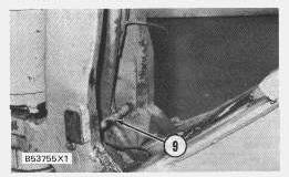
10. Remove pipe (9).
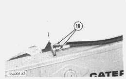
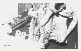
11. Remove hose assemblies(10).
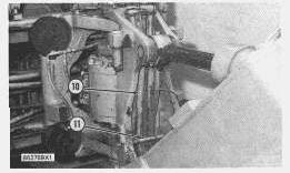
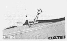
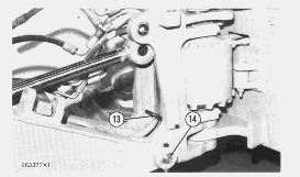
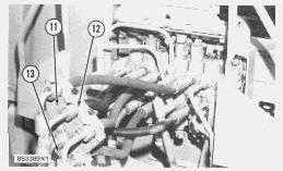
12. Put a nylon strap around the boom (12), fasten a hoist and give support to the weight of the boom. The weight is 309 kg (685 lb.).
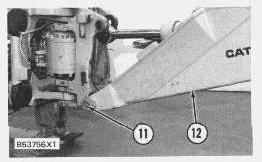
13. Remove two pins(11).
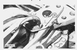
14. Put boom (12) in position on wood blocks.
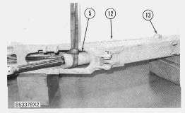
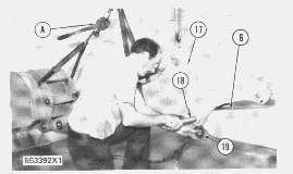
15. Fasten a nylon strap and hoist to cylinder (5).
16. Remove pin (13) and pull cylinder (5) out of boom (12). Weight is 84 kg (185 lb.).
15. Put marks of identification on the hose connections and remove the hydraulic hose assemblies from the boom cylinder.
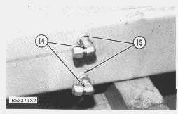
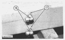
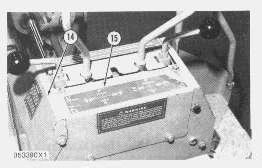
Remove fittings(14) and remove nuts (15).
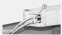
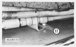
18. Remove nuts (17) and pull hose and tube assembliesout of the boom.
Install Boom And Boom Cylinder
1. Put the hose assemblies and tube assemblies in the boom and install the nuts to hold bracket (1) in place.
2. Install clamp (2).
3. Fasten a nylon strap and hoist to boom cylinder (3).
4. Connect the hydraulic hoses to the boom cylinder.
5. Put boom cylinder (3) in position in the boom and install the pin.
6. Install nuts(4) and fittings (5) on the tube assemblies.
7. Fasten a nylon strap and hoist to the boom and put boom (6) in position on the swing frame. Install two pins(7).
8. Fasten a nylon strap and hoist to the rod end of boom cylinder (8) and put the rod eye in position in the swing frame and install pin (9).
9. Put six hose assemblies(10) in position in the swing frame and install pipe (11).
10. Install bracket (12) to hold the six hose assemblies in place in the swing frame.

11. Put the six hose assemblies (10) through the opening in the top of the swing frame and connect the hose assembliesaccording to previousidentification.
12. Connect hose assemblies(11) according to previousidentification.

13. Fasten nylon straps to the stick frame and bucket and fasten tooling (A) and a hoist.
14. Put stick frame (12) in position on boom frame (6).
15. Install pin (13) and spacers(14). Install spacers (14) as necessary to put hoe stick (12) in the center of the boom.
16. Fasten a nylon strap and hoist to stick frame (12). Lift the stick frame and boom and install tooling (B) at the junction of the stick frame and boom.
NOTE: Move the boom control valve to the "RAISE" position during thisprocedure. end by:
a) install hoe stick cylinder
Copyright 1993 - 2020 Caterpillar Inc. All Rights Reserved. Private Network For SIS Licensees. Wed Aug 26 10:32:53 UTC+0530 2020
Product: TRACK LOADER
Model: 931B TRACK LOADER 25Y
Configuration: 931B TRACK LOADER / POWER SHIFT / 25Y00001-UP (MACHINE) POWERED BY 3204 ENGINE
Disassembly and Assembly
D3B & 931B BACKHOE
Media Number -SENR2593-00
Boom And Boom Cylinder
Publication Date -01/12/1981
Date Updated -11/10/2001
SMCS - 5456-11; 5456-12; 6501
Remove Boom And Boom Cylinder

start by:
a) remove hoe stick cylinder
1. Fasten a nylon strap and hoist to hoe stick (1). Lift the hoe stick enough to let the support stand be removed.
2. Lower the boom on to blocks.
NOTE: Move the control valve to the LOWER position during this procedure.
3. Pull bucket cylinder hydraulic hoses (2) out of hoe stick (1).
4. Wrap a nylon strap around the hoe stick and fasten the strap to a hoist. Fasten a nylon strap to the bucket and fasten tooling (A) to a hoist.
5. Remove pin (3) and remove the bucket and stick as an assembly away from boom (4). The weight is 415 kg (915 lb.).
6. Fasten a nylon strap to boom hydraulic cylinder (5).
7. Remove pin (6) and lower the rod on to a wood block.
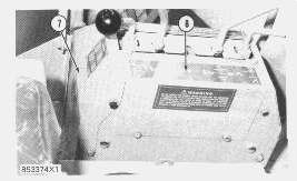
8. Remove covers (7) and (8) from the console.
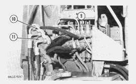
9. Put marks of identification on the hydraulic hose connections at the control valve (9) and the location of hose assembliesin brackets (10) and (11).
10. Remove brackets(10) and (11).
11. Disconnect six hose assembliesat control valve (9).
12. Fasten a nylon strap and hoist to boom (4). Lift the boom, remove the wood block and lower the boom to the ground.
13. Put marks of identification on the connections for hose assemblies on the boom and remove the hose assembliesfrom boom (4).
14. Put a nylon strap around the boom, fasten a hoist and give support to the weight of the boom. Weight is 309 kg (685 lb.).
15. Remove pipe (13) and two pins(14).
16. Put boom (4) in position on wood blocks as shown.
17. Fasten a nylon strap and hoist to cylinder (5).
18. Remove pin (15) and pull cylinder out of boom. Weight is 84 kg (185 lb.).
19. Put marks of identification on the hose connections and remove the hydraulic hose assemblies from the boom cylinder.
20. Remove fittings(16) and remove nuts (17).
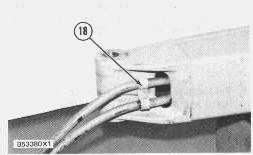
21. Remove bracket (18).
22. Remove nuts (19) and pull hose and tube assembliesout of the boom.
Install Boom And Boom Cylinder

1. Put the hose assemblies and tube assemblies in the boom and install the nuts to hold bracket (1) in place.
2. Install clamp (2).
3. Fasten a nylon strap and hoist to boom cylinder (3).
4. Connect the hydraulic hoses to the boom cylinder.
5. Put boom cylinder (3) in position in the boom and install the pin.

6. Install nuts(4) and fittings (5) on the tube assemblies.
7. Fasten a nylon strap and hoist to the boom and put boom (6) in position on the swing frame. Install two pins(7).
8. Fasten a nylon strap and hoist to boom cylinder rod (8) and put the rod eye in position on the swing frame and install pin (9).
9. Put the hose assemblies in position in the swing frame and install pipe (10) and bolt.
10. Put the hose assemblies in position in clamps(11), (12) and (13) according to previous identification. Do not tighten the bolts at this time.
11. Connect the hose assemblies to the control valve according to previous identification.
12. Tighten the clamp bolts.
13. Install covers (14) and (15).
14. Connect hose assemblies(16) according to previousidentification.
15. Fasten nylon straps to the stick frame and bucket and fasten tooling (A) and a hoist.
16. Put stick frame (17) in position on boom frame (6).
17. Install pin (18) and spacers(19). Install spacers (19) as necessary to put hoe stick in the center of the boom.
18. Fasten a nylon strap and hoist to stick frame (17). Lift the stick frame and boom and install tooling (B) at the junction of the stick frame and boom.
NOTE: Move the boom control valve to the "RAISE" position during thisprocedure.
end by:
a) install hoe stick cylinder
Product: TRACK LOADER
Model: 931B TRACK LOADER 25Y
Configuration: 931B TRACK LOADER / POWER SHIFT / 25Y00001-UP (MACHINE) POWERED BY 3204 ENGINE
Disassembly and Assembly
D3B & 931B BACKHOE
Media Number -SENR2593-00
Bucket (Backhoe)
SMCS - 6503-11; 6503-12
Remove Bucket (Backhoe)
Publication Date -01/12/1981
Date Updated -11/10/2001
1. Use the backhoe control valve to put the stick (3) in the extended position and carefully lower the stick (3) on to tooling (A).
2. Lower the bucket (1) until the tipsmake contact with the ground.
3. Remove pin (2) and spacer.
4. Fasten a nylon strap and tooling (B) to the bucket (4).
5. Remove pin (5) and remove bucket (1). The weight of the bucket is 124 kg (275 lb.).
6. Inspect bearings (4) for wear or damage and remove if necessary.
Install Bucket (Backhoe)
This is the sample of the manual
Click on the download link for complete Manual
1. Install bearings (1) in the bucket.
2. Fasten a nylon strap and tooling (B) to the bucket.
3. Install pin (2). Install the washers and cotter pins.
4. Install pin (4) and spacer (3). Install the washers and cotter pins.
5. Remove the nylon strap.
6. Start the machine and carefully use the backhoe control valve to lift the stick.
7. Remove tooling (A).
8. Carefully lower the bucket to the ground.