Product: WHEEL LOADER
Model: 924K WHEEL LOADER KW4
Configuration: 924K Small Wheel Loader KW400001-UP (MACHINE) POWERED BY C7.1 Engine
Disassembly and Assembly
924K, 930K and 938K Wheel Loaders Power Train
Accumulator (Hydrostatic)
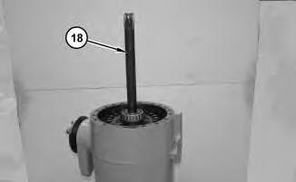
SMCS - 5077-H7 Specifications Illustration 1
1 Specification for 373-6953 Accumulator Gp (HYDROSTATIC)
1
Cap Torque to 1.6 ± 0.1 N·m (14.2 ± 0.9 lb in). - - - Charging medium is dry nitrogen. - - - Capacity of oil is 0.83 L (50.65 cubic inch)
- - - Capacity of gas is 0.83 L (50.65 cubic inch).
- -Precharge pressure at 21.1 °C (70.0 °F) is 2150 ± 110 kPa (312 ± 16 psi).
- - - Maximum operating pressure is 27500 kPa (3989 psi).
- - - Maximum operating temperature is 121 °C (250 °F).
- - -
Removal Procedure
Start By:
a. Connect the steering frame lock.
b. Release the hydraulic system pressure.
Personal injury can result from the sudden release of high pressure oil. Be sure the engine has been shut off for a minimum of five minutes to be sure that the accumulator pressure is zero.
The accumulator is filled with dry nitrogen. Do not loosen or remove the valve or cap from the top of the accumulator. A purge screw at the bottom of the accumulator can be used to release the pressure that is left in the system.
Personal injury can result from hydraulic oil pressure and hot oil.
Hydraulic oil pressure can remain in the hydraulic system after the engine has been stopped. Serious injury can be caused if this pressure is not released before any service is done on the hydraulic system.
Make sure all of the attachments have been lowered, oil is cool before removing any components or lines. Remove the oil filler cap only when the engine is stopped, and the filler cap is cool enough to touch with your bare hand.
2
3
Illustration
g02858296
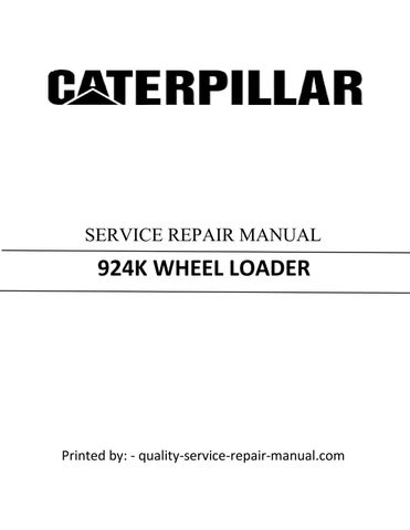
1. Remove cover (1).
Illustration
g02867549
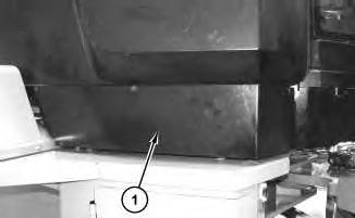
2. Disconnect hose assembly (2).
3. Loosen clamps (4) and remove hydrostatic accumulator (3).
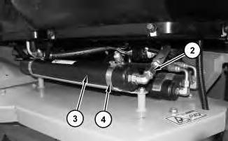
Illustration 4
4. Remove gas valve cap (5), the gas valve, and the O-ring seals.
Installation Procedure
1. Install hydrostatic accumulator (3) in the reverse order of removal.
a. Tighten gas valve cap (5) to a torque of 1.6 ± 0.1 N·m (14.16 ± 0.89 lb in).
Copyright 1993 - 2021 Caterpillar Inc. All Rights Reserved. Private Network For SIS Licensees. Fri Aug 27 10:44:32 UTC+0530 2021
Product: WHEEL LOADER
Model: 924K WHEEL LOADER KW4
Configuration: 924K Small Wheel Loader KW400001-UP (MACHINE) POWERED BY C7.1 Engine
Disassembly and Assembly
924K, 930K and 938K Wheel Loaders Power Train
Axle Housing - Front and Rear Axle Housings
SMCS - 3260
S/N - DYB1-UP
S/N - ENC1-UP
S/N - EYE1-UP
S/N - FRK1-UP
S/N - HJF1-UP
S/N - KW41-UP
S/N - P3K1-UP
S/N - PWR1-UP
S/N - REP1-UP
S/N - RHN1-UP
S/N - SNZ1-UP
S/N - T681-UP
S/N - W8K1-UP
Removal Procedure
i05268485
This is the sample of the manual click on the download link for complete manual
DOWNLOAD LINK
Table 1
Required Tools
Tool Part Number Part Description
A 1P-2420 Transmission Repair Stand 1
B 6V-2156 Link Bracket 3
C 4C-8502 Spanner Wrench As 1
D 1H-3107 Puller Group 1
E 5F-7343 Puller Group 1
F 1P-0074 Slide Hammer Puller 1
G 1U-8697 Duo-Cone Seal Installer As 1
H - Loctite High Flex GM -
Start By:
A. Remove the axle trunnion (front and rear) on the oscillating axle housing.
B. Remove the fixed axle.
Note: Cleanliness is an important factor. Before the disassembly procedure, thoroughly cleaned the exterior of the component to help prevent dirt from entering the internal mechanism.
1. Drain the oil from the axle housing into a suitable container for storage or disposal. The capacity of the axle housing is approximately 17.4 L (4.6 US gal).
Illustration 1 g00663942
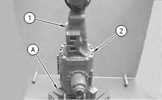
2. Place axle assembly (1) on Tooling (A) . The weight of axle housing assembly (1) is approximately 590 kg (1300 lb).
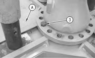
3. Attach a suitable lifting device to axle housing assembly (1) . The weight of axle housing assembly (1) is approximately 147 kg (325 lb). Remove bolts (2) and remove axle housing assembly (1) .
Illustration 2
Illustration 3
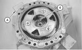
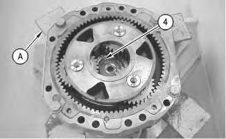
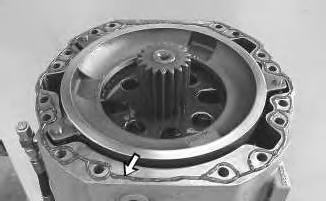
4. Position the axle housing on Tooling (A) , as shown. Install bolt (3) in the axle, as shown.
5. Remove retaining ring (4) .
g00670398
g00670395
4
6. Install Tooling (B) and a suitable lifting device to carrier assembly, as shown. The weight of carrier assembly (5) is approximately 28 kg (62 lb). Remove carrier assembly (5) .
5
6
Illustration
g00670400
Illustration
g00891526
Illustration
g00670403
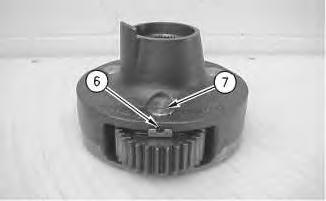
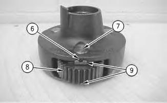
7. Drive pins (6) into shaft (7) .
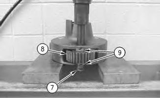
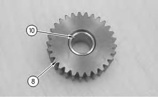
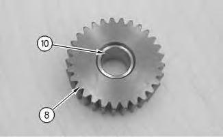
8. Use a suitable press to remove shaft (7) . Remove gear (8) and washers (9) .
9. Remove pins (6) from shaft (7) .
Illustration 7
10. Remove bearing (10) from gear (8) .
11. Repeat Steps 7 through 10 for the remaining two gears.
8
g00670404
Illustration
g00670405
Illustration 9
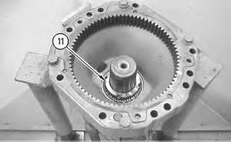
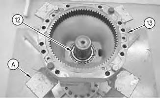
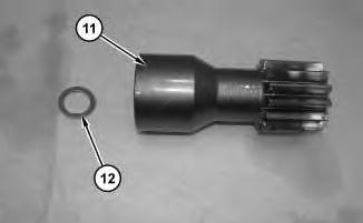
12. Use Tooling (C) in order to remove nut (11) .
Illustration 10
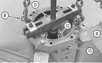
13. Attach Tooling (B) and a suitable lifting device to axle housing (13) . The weight of axle housing (13) is approximately 88 kg (195 lb). Use Tooling (D) in order to separate axle housing (13) from the axle shaft.
14. Remove bearing cone (12) .
g00670407
g00670410
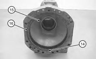
Illustration 11
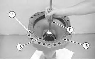
15. Use Tooling (F) in order to remove bearing cup (15) .
Note: Removal of ring gear (16) will destroy the ring gear.
16. Use one of the following methods in order to remove ring gear (16) . Use a torch in order to cut ring gear (16) at pins (14) . Make three welds around the inside of ring gear (16) . This will cause ring gear (16) to shrink.
17. Remove pin (14) .
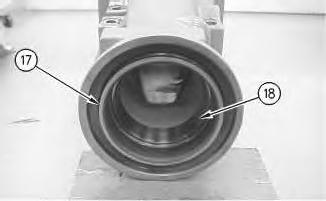
Illustration 12
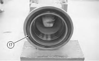
18. Remove seal (17) .
g00670663
g00891527
Illustration 13
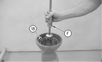
19. Use Tooling (F) in order to remove bearing cup (18) .
Illustration 14
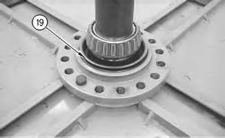
20. Use Tooling (G) to remove seal (19) .
g00670665
g00670664
Illustration 15 g00670676
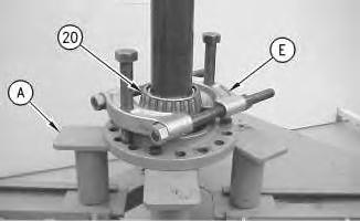
21. Position the axle on Tooling (A) , as shown.
22. Use Tooling (E) in order to remove bearing cone (20) .
Installation Procedure
Note: Cleanliness is an important factor. Before assembly, thoroughly clean all parts in cleaning fluid. Allow the parts to air dry. Wiping cloths or rags should not be used to dry parts. Lint may be deposited on the parts which may cause later trouble. Inspect all parts. If any parts are worn or damaged, use new parts for replacement.
Illustration 16
1. Use Tooling (G) in order to install seal (19) . Refer to Disassembly and Assembly, "Duo-Cone Conventional Seals - Install" for the proper procedure.
Note: Lubricate the bearing with the lubricant that is being used.
2. Raise the temperature of bearing cone (20) .
3. Install bearing cone (20) .
g00671305
17
4. Lower the temperature of bearing cup (18) .
5. Install bearing cup (18) . Use Tooling (G) in order to install seal (17) . Refer to Disassembly and Assembly, "Duo-Cone Conventional Seals - Install" for the proper procedure.
Illustration 18
g01132120
6. Lower the temperature of bearing cup (15) .
7. Install bearing cup (15) .
8. Lower the temperature of ring gear (16) and install ring gear (16) . Install pins (14) and peen the housing in order to retain pins (14) .
Illustration
g00671344
Illustration 19
9. Use a suitable lifting device and Tooling (B) in order to install axle housing (13) onto the axle shaft. The weight of axle housing (13) is approximately 88 kg (195 lb). Use Tooling (A) in order to support axle housing (13) .
10. Raise the temperature of bearing cone (12) .
11. Install bearing cone (12) .
12. Lubricate bearing cone (12) with the lubricant that is being sealed.
Illustration 20
g00671536
g00670405
Illustration 21
g00670407
Note: Lubricate nut (11) with the lubricant that is being sealed.
13. Install nut (11) . Use Tooling (C) in order to tighten nut (11) . Leave slight bearing end play.
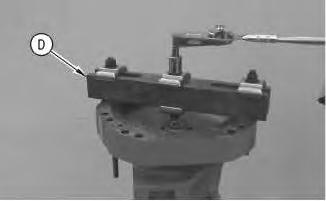
Illustration 22
g00671551
14. Use Tooling (A) in order to support the axle shaft. Install Tooling (D) , as shown. Install a bolt in the center of Tooling (D) . Use a torque wrench in order to rotate the axle housing and check the rolling torque (SD) . This is the amount of seal drag.
15. Use Tooling (C) in order to tighten nut (11) . Check the rolling torque (RT) . This is the total rolling torque. Subtract the seal drag torque (SD) from the total rolling torque (RT) . This is the rolling torque of the axle bearings. Tighten nut (11) until a rolling torque of the axle bearings is 3 N·m to 8 N·m (27 lb in to 70 lb in). The rolling torque for used axle bearings should be 2 N·m to 4.5 N·m (18 lb in to 40 lb in).
Illustration 23
16. Install bearing (10) in gear (8) .
Illustration 24
17. Install gear (8) and washers (9) .
18. Install shaft (7) .
g00670404
g00671595
Illustration 25 g01131675
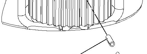
Note: The openings of pins (6) must be 180 degrees away from each other. The openings of pins (6) must be parallel to the carrier deck. Refer to illustration 25.
19. Install pins (6) .
20. Deform pin holes slightly with a chisel.
21. Repeat Steps 16 through 19 for the remaining gear assemblies.
26
22. Use Tooling (B) and a suitable lifting device in order to install carrier assembly (5) . The weight of carrier assembly (5) is approximately 28 kg (62 lb).
Illustration 27
23. Install retaining ring (4) .
24. Use a suitable lifting device in order to remove the axle housing from Tooling (A) . The weight of the axle housing is approximately 147 kg (325 lb).
Illustration
g00670400
g00670395
Illustration 28
g01132124
25. Clean the mating surfaces of the axle housing and apply a continuous bead of Tooling (H) .
Illustration 29
g00663942
26. Use a suitable lifting device in order to install axle housing (1) . The weight of axle housing assembly (1) is approximately 147 kg (325 lb). Install bolts (2) .
End By:
a. Install the axle trunnion (front and rear) on the oscillating axle housing.
b. Install the fixed axle housing.
Copyright 1993 - 2021 Caterpillar Inc. All Rights Reserved. Private Network For SIS Licensees. Fri Aug 27 10:53:05 UTC+0530 2021
Product: WHEEL LOADER
Model: 924K WHEEL LOADER KW4
Configuration: 924K Small Wheel Loader KW400001-UP (MACHINE) POWERED BY C7.1 Engine
Disassembly and Assembly
924K, 930K and 938K Wheel Loaders Power Train
Axle Housing - Front Axle
SMCS - 3260
S/N - FRK1-UP
S/N - HFW1-UP
S/N - KW41-UP
S/N - P3K1-UP
S/N - REP1-UP
S/N - SNZ1-UP
S/N - SWL1-UP
S/N - T681-UP
S/N - W8K1-UP
S/N - XXT1-UP
Removal Procedure
Table 1
Required Tools
Tool Part Number Part Description Qty
A 138-7576 Link Bracket 1
i04642161
B 241-3790 Link Bracket 2
C 1U-6400 Three Jaw Puller 1
D 1U-5230 Hand Hydraulic Pump 1
Start By:
a. Remove the front axle.
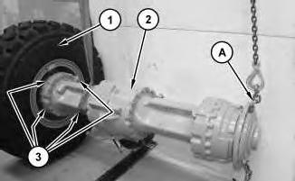
1. Attach Tooling (A) and suitable lifting devices to front axle (2). The weight of front axle (2) is approximately 1270 kg (2800 lb). Use Tooling (A) and the suitable lifting devices in order to position front axle (2) to the outside of wheel (1). Install four bolts (3) in order to secure front axle (2) to wheel (1).
Note: This step must be done on a flat level surface.
2. Use Tooling (A) and the suitable lifting devices in order to set wheel (1) so that front axle (2) is in a verticle position with wheel (1) resting flat on the ground.
Illustration 1
g02786949
Illustration 2
g02859660
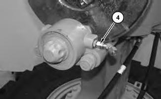
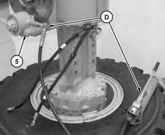
3. Remove fittings (4.)
3
4. Remove bolts (5) and the locking nuts in order to remove the parking brake caliper. Attach Tooling (D) in order to release the parking brake.
4
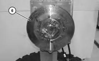
5. Remove brake rotor (6).
Illustration
g02859677
Illustration
g02859696
Illustration 5
g02787117
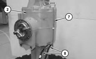
6. Remove tube assembly (7) and hose assemblies (8) from front axle (2).
Illustration 6
g02787176
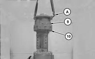
7. Attach Tooling (A) and a suitable lifting device to final drive and brake housing (9). The weight of final drive and brake housing (9) is approximately 218 kg (480 lb). Remove bolts (10). Use Tooling (A) and the suitable lifting device in order to remove final drive and brake housing (9) and the O-ring seal.
Illustration 7 g02787278
Illustration 8 g02788226
8. Remove sun gear shaft (11).
Note: Sun gear shaft (11) may come off with the final drive and brake housing (9) or stay with the axle shaft when the final drive and brake housing (9) is removed.
9. Remove shim (12).
Note: Shim (12) may be located on the end of the axle shaft or inside sun gear shaft (11).
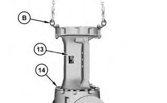
Illustration 9 g02788323
10. Attach Tooling (B) and a suitable lifting device to axle housing (13). The weight of axle housing (13) is approximately 172 kg (380 lb). Remove bolts (14). Use Tooling (B) and the suitable lifting device in order to remove axle housing (13).
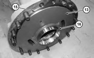
Illustration 10
11. Remove O-ring seal (15) and bearing cup (16) from axle housing (13).
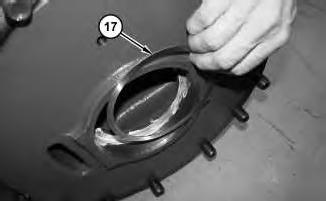
Illustration 11
12. Remove shim (17).
g02788477
Illustration 12
13. Remove axle shaft (18).
g02788486
g02788436
This is the sample of the manual click on the download link for complete manual