DOWNLOAD LINK
2
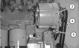
4. Install tension adjustment bolt (5) and the washer through the adjustment bracket and into the alternator. Do not tighten tension adjustment bolt (5) at thistime.
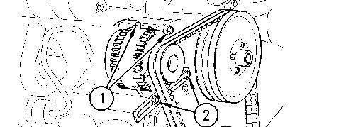
5. Install V-belts (4) in position on the pulley. Adjust the tension on V-belts (4) by moving alternator (3) away from the engine. Tighten tension adjustment bolt (5) after the proper belt tension is made. Refer to Specifications, "Belt Tension Chart" for the correct tension of the V-belts.
Illustration 3
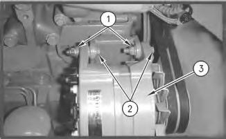
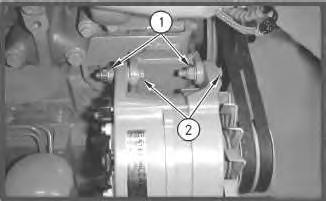
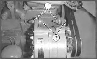
6. Tighten nuts (1) in order to secure the alternator in position on the engine.
Copyright 1993 - 2021 Caterpillar Inc. All Rights Reserved. Private Network For SIS Licensees. Sat Jun 26 11:05:47 UTC+0530 2021
Illustration
g00907181
g00907180
Product: WHEEL LOADER
Model: 924GZ WHEEL LOADER WGX
Configuration: 924G 924Gz Wheel Loader WGX00001-UP (MACHINE) POWERED BY 3056E Engine
Disassembly and Assembly
3056E Engine for Caterpillar Built Machines
Media Number -RENR2400-07 Publication Date -01/02/2006 Date Updated -03/08/2020
Alternator - Remove
SMCS - 1405-011
Removal Procedure
1. Disconnect the electrical wires from the alternator.
Illustration 1 g00999586
2. Loosen the fasteners for the pivot (1) from the alternator bracket.
i01895190
3. Loosen the fasteners for the adjustment link (2) and slide the alternator toward the engine in order to slacken the V-belts. Remove the V-belts from the pulley.
4. Remove the fasteners for the adjustment link (2) and remove the adjustment link from the alternator.
5. Support the alternator. Remove the fastenersfor the pivot (1) and remove the alternator from the engine.
Copyright 1993 - 2021 Caterpillar Inc. All Rights Reserved. Private Network For SIS Licensees.
Sat Jun 26 11:05:26 UTC+0530 2021
Product: WHEEL LOADER
Model: 924GZ WHEEL LOADER WGX
Configuration: 924G 924Gz Wheel Loader WGX00001-UP (MACHINE) POWERED BY 3056E Engine
Disassembly and Assembly
3056E Engine for Caterpillar Built Machines
Media Number -RENR2400-07
Alternator - Remove
SMCS - 1405-011
Removal Procedure
-03/08/2020
i01774077
1. Place an index mark on all of the electrical wires that are connected to the alternator. Disconnect the electrical wires from the alternator.
1
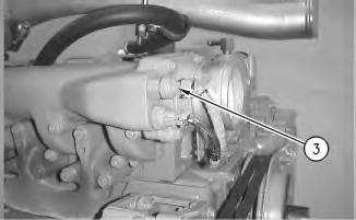
2. Loosen nuts (1) and bolts(2) from the alternator bracket.
Illustration
g00907180
2
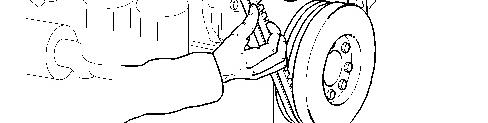
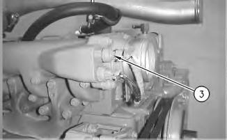
3. Loosen tension adjustment bolt (5) and slide alternator (3) toward the engine. Remove Vbelts (4) from the pulley.
4. Remove tension adjustment bolt (5) and the washer from alternator (3).
Illustration 3
5. Remove nuts(1) and the washers.
g00908147
6. Remove bolts (2) from the alternator bracket.
7. Remove alternator (3) from the engine. Copyright 1993 - 2021 Caterpillar Inc. All Rights Reserved. Private Network For SIS Licensees. Sat Jun 26 11:05:13 UTC+0530 2021
Illustration
g00907181
Product: WHEEL LOADER
Model: 924GZ WHEEL LOADER WGX
Configuration: 924G 924Gz Wheel Loader WGX00001-UP (MACHINE) POWERED BY 3056E Engine
Disassembly and Assembly
3056E Engine for Caterpillar Built Machines
Media Number -RENR2400-07 Publication Date -01/02/2006 Date Updated -03/08/2020
Atmospheric Pressure Sensor - Remove and Install
SMCS - 1923-010
Removal Procedure
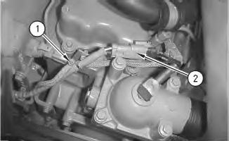
Illustration 1 g00906557
i01773087
1. Cut cable strap (1) and disconnect harness assembly (2).
Illustration 2
2. Remove atmospheric pressure sensor (3).
Installation Procedure
Illustration 3
1. Install atmospheric pressure sensor (3).
Illustration 4
2. Connect harness assembly (2) and secure harness assembly (2) with cable strap (1). Copyright 1993 - 2021 Caterpillar Inc. All Rights Reserved. Private Network For SIS Licensees. Sat Jun 26 11:03:18 UTC+0530 2021
g00906558
g00906557
Product: WHEEL LOADER
Model: 924GZ WHEEL LOADER WGX
Configuration: 924G 924Gz Wheel Loader WGX00001-UP (MACHINE) POWERED BY 3056E Engine
Disassembly and Assembly
3056E Engine for Caterpillar Built Machines
Media Number -RENR2400-07
Bearing Clearance - Check
SMCS - 1203-535; 1219-535
Measurement Procedure Table 1
Required Tools Tool
Plastic Gauge (Green)
Gauge (Red)
Plastic Gauge (Blue)
to 0.229 mm (0.004 to 0.009 inch)
Plastic Gauge (Yellow)
to 0.510 mm (0.009 to 0.020 inch)
Note: Plastic gauge may not be necessary when the engine is in the chassis.
NOTICE
Keep all partsclean from contaminants.
Contaminants may cause rapid wear and shortenedcomponent life.
i05977048
Note: Cat does not recommend the checking of the actual bearing clearancesparticularly on small engines. Thisisbecause of the possibility of obtaining inaccurate results and the possibility of damaging the bearing or the journal surfaces. Each Cat engine bearing is quality checked for specific wall thickness.
Note: The measurements should be within specifications and the correct bearings should be used. If the crankshaft journals and the bores for the block and the rods were measured during disassembly, no further checksare necessary. However, if the technician still wants to measure the bearing clearances, Tooling (A) is an acceptable method. Tooling (A) is less accurate on journals with small diametersif clearances are lessthan 0.10 mm (0.004 inch).
NOTICE
Lead wire, shim stock or a dial bore gauge can damage the bearing surfaces.
The technician must be very careful to use Tooling (A) correctly. The following points must be remembered:
• Ensure that the backs of the bearings and the bores are clean and dry.
• Ensure that the bearing locking tabs are properly seated in the tab grooves.
• The crankshaft must be free of oil at the contact pointsof Tooling (A).
1. Put a piece of Tooling (A) on the crown of the bearing that is in the cap.
Note: Do not allow Tooling (A) to extend over the edge of the bearing.
2. Use the correct torque-turn specifications in order to install the bearing cap. Do not use an impact wrench. Be careful not to dislodge the bearing when the cap isinstalled.
Note: Do not turn the crankshaft when Tooling (A) is installed.
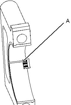
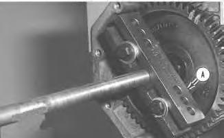
3. Carefully remove the cap, but do not remove Tooling (A). Measure the width of Tooling (A) while Tooling (A) isin the bearing cap or on the crankshaft journal. Refer to Illustration 1.
Illustration 1 g01152855
TypicalExample
4. Remove all of Tooling (A) before you install the bearing cap.
Note: When Tooling (A) is used, the readings can sometimes be unclear. For example, all parts of Tooling (A) are not the same width. Measure the major width in order to ensure that the partsare within the specification range. Refer to SpecificationsManual, "Connecting Rod Bearing Journal" and Specifications Manual, "Main Bearing Journal" for the correct clearances. Copyright 1993 - 2021 Caterpillar Inc. All Rights Reserved. Private Network For SIS Licensees. Sat Jun 26 11:03:06 UTC+0530 2021
Product: WHEEL LOADER
Model: 924GZ WHEEL LOADER WGX
Configuration: 924G 924Gz Wheel Loader WGX00001-UP (MACHINE) POWERED BY 3056E Engine
Disassembly and Assembly
3056E Engine for Caterpillar Built Machines
Media Number -RENR2400-07
Camshaft - Remove and Install
SMCS - 1210-010
Removal Procedure
Start By:
i01755583
a. Remove the rocker shaft assembly and the pushrods. Refer to Disassembly and Assembly, "Rocker Shaft and Pushrod - Remove".
b. Remove the fuel transfer pump. Refer to Disassembly and Assembly, "Fuel Transfer PumpRemove".
c. Remove the front housing. Refer to Disassembly and Assembly, "Housing (Front)Remove".
d. Remove the camshaft gear. Refer to Disassembly and Assembly, "Camshaft Gear - Remove and Install".
NOTICE
Keep all partsclean from contaminants.
Contaminants may cause rapid wear and shortenedcomponent life.
NOTICE
Care must be taken to ensure that fluids are containedduring performance of inspection, maintenance, testing, adjusting and repair of the product. Be prepared to collect the fluid with suitable containers
before opening any compartment or disassembling any component containing fluids.
Refer to Special Publication, NENG2500, "Caterpillar Dealer Service Tool Catalog" for tools and suppliessuitable to collect and contain fluids on Caterpillar products.
Dispose of all fluids according to local regulations and mandates.
1. Turn the engine upside-down so the valve lifters are held in a position away from the camshaft.
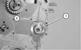
1
2. Remove thrust washer (1). Make a note of the location of the hollowdowel (X) for installation purposes.
Illustration 2
NOTICE
Do not damage the lobes or the bearings whenthe camshaft is removed or installed.
Illustration
g00546803
g00546869
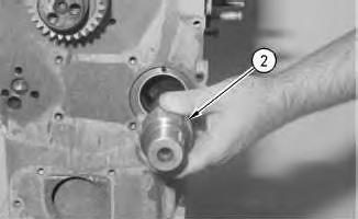
3. Carefully remove camshaft (2) from the engine.
Installation Procedure
Illustration 3
g00546869
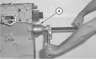
Note: Ensure that camshaft (2) is clean. Lubricate camshaft (2) with clean engine oil prior to installation.
1. Carefully install camshaft (2) in the engine.
Illustration 4
g00546803
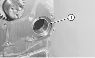
2. Put thrust washer (1) in position. Make sure that thrust washer (1) is aligned with hollow Dowel (X).
End By:
a. Install the camshaft gear. Refer to Disassembly and Assembly, "Camshaft Gear - Remove and Install".
b. Install the front housing. Refer to Disassembly and Assembly, "Housing (Front) - Install".
c. Install the fuel transfer pump. Refer to Disassembly and Assembly, "Fuel Transfer PumpInstall".
d. Install the rocker shaft and the pushrods. Refer to Disassembly and Assembly, "Rocker Shaft and Pushrods - Install".
Copyright 1993 - 2021 Caterpillar Inc. All Rights Reserved. Private Network For SIS Licensees.
Sat Jun 26 10:56:55 UTC+0530 2021
Product: WHEEL LOADER
Model: 924GZ WHEEL LOADER WGX
Configuration: 924G 924Gz Wheel Loader WGX00001-UP (MACHINE) POWERED BY 3056E Engine
Disassembly and Assembly
3056E Engine for Caterpillar Built Machines
Media Number -RENR2400-07
Camshaft Bearings - Remove and Install
SMCS - 1211-010
Removal Procedure
Table 1
Required Tools
Start By:
A. Remove the camshaft. Refer to Disassembly and Assembly, "Camshaft - Remove and Install".
NOTICE
Keep all partsclean from contaminants.
Contaminants may cause rapid wear and shortenedcomponent life.
i01778792
Illustration 1
g00546238
1. Use Tooling (A). Apply 4C-5591 Anti-Seize Compound to the threads of Tooling (A) .
Illustration 2
g00546333
2. Remove camshaft bearings(1) from the cylinder block.
Installation Procedure
Table 2
Required Tools
Keep all partsclean from contaminants.
Contaminants may cause rapid wear and shortenedcomponent life.
Illustration 3
Illustration 4
1. Use Tooling (A) in order to install camshaft bearings (1). Apply 4C-5591 Anti-Seize Compound to the threads of Tooling (A) .
End By: Install the camshaft. Refer to Disassembly and Assembly, "Camshaft - Remove and Install".
1993 - 2021
g00546238
g00546333
Product: WHEEL LOADER
Model: 924GZ WHEEL LOADER WGX
Configuration: 924G 924Gz Wheel Loader WGX00001-UP (MACHINE) POWERED BY 3056E Engine
Disassembly and Assembly
3056E Engine for Caterpillar Built Machines
Media Number -RENR2400-07
i03140046
Camshaft Gear - Remove and Install
SMCS - 1210-010-GE
Removal Procedure Table 1
Required Tools
Start By:
a. Remove the fan. Refer to Disassembly and Assembly, "Fan - Remove and Install".
b. Remove the front cover. Refer to Disassembly and Assembly, "Front Cover - Remove".
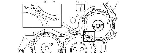
1 g00541128
1. Rotate the crankshaft until the timing marks on the crankshaft gear, the camshaft gear, and the fuel injection pump gear are aligned, as shown.
Note: The timing marks on the idler gear may not be aligned. This is caused by the difference in the speed of the rotation of the idler gear.
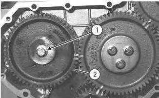
2 g00541130
2. Remove bolt (1) and the washer from the camshaft gear (2).
Illustration
Illustration
3 g00541131
3. Install Tooling (A) and remove camshaft gear.
Note: Do not lose the key from the camshaft gear.
4. Inspect the camshaft gear for wear and damage. Replace the gear, if necessary.
Installation Procedure
Illustration 4
g00541130
1. Install camshaft gear (2) in the front housing.
Note: When you install the camshaft gear, ensure that the teeth that have the timing marks are facing toward the front. Also, ensure that the key isaligned properly in the keyway. If necessary, tap the gear with a soft hammer in order to seat the key in the keyway.
2. If necessary, remove the idler gear in order to align the gear teeth correctly.
3. Install the washer and bolt (1) on the camshaft gear. Tighten bolt (1) to a torque of 95 N·m (70 lb ft).
Note: Ensure that the timing marks on the camshaft gear, the crankshaft gear, and the fuel injection pump gear are aligned.
Illustration
4. If a new camshaft gear is used, check the backlash of the camshaft gear. The minimum backlash for a new gear is0.08 mm (0.003 inch).
End By:
a. Install the front cover. Refer to Disassembly and Assembly, "Front Cover - Install".
b. Install the fan. Refer to Disassembly and Assembly, "Fan - Remove and Install".
Copyright 1993 - 2021 Caterpillar Inc. All Rights Reserved. Private Network For SIS Licensees. Sat Jun 26 10:57:08 UTC+0530 2021
This is the sample of the manual click on the download link for complete manual