DOWNLOAD LINK
For some reason if link does not work download this pdf and then click
8
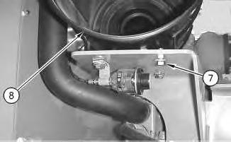
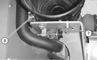
2. Place air cleaner assembly (8) in position.
3. Install four bolts (7) .
9
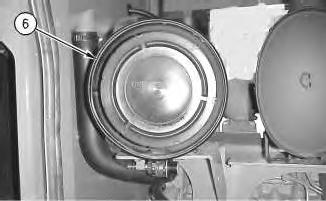
4. Install air filter (6) .
Illustration
g00642915
Illustration
g00642912
10
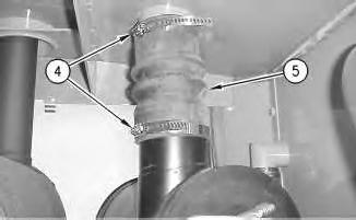
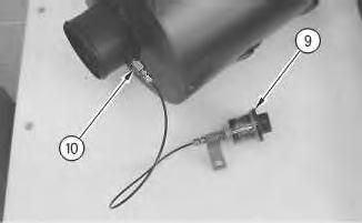
5. Connect hose (5) to the air cleaner housing.
6. Tighten two hose clamps (4) .
Illustration 11
g00642907
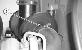
7. Tighten hose clamp (3) to a torque of 4 ± 1 N·m (3.0 ± 0.7 lb ft).
Illustration
g00642910
12
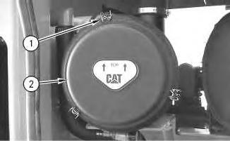
8. Install housing cover (2) .
9. Connect three clamps (1) .
10. Close the right door and the left door.
End By: Separate the steering frame lock. Refer to Disassembly and Assembly, "Steering Frame Lock - Separate and Connect" for the proper procedure.
1993 - 2021 Caterpillar Inc.
Product: WHEEL LOADER
Model: 924G WHEEL LOADER AAN
Configuration: 924G and 924Gz Wheel Loader AAN00001-UP (MACHINE) POWERED BY 3056 Engine
Disassembly and Assembly
924G and 924Gz Wheel Loaders Engine Supplement
i01227587
Air Inlet Heater - Remove and Install
SMCS - 1090-010
Removal Procedure
Start By:
a. Connect the steering frame lock. Refer to Disassembly and Assembly, "Steering Frame LockSeparate and Connect".
Personal injury or death can result from a fire.
Fuel leaked or spilled onto hot surfaces or electrical components can cause a fire.
Clean up all leaked or spilled fuel. Do not smoke while working on the fuel system.
Turn the disconnect switch OFF or disconnect the battery when changing fuel filters.
Care must be taken to ensure that fluids are contained during performance of inspection, maintenance, testing, adjusting, and repair of the product. Be prepared to collect the fluid with suitable containers before opening any compartment or disassembling any component containing fluids.
Refer to Special Publication, NENG2500, "Dealer Service Tool Catalog" for tools and supplies suitable to collect and contain fluids on Cat products.
Dispose of all fluids according to local regulations and mandates.
NOTICE
Do not allow dirt to enter the fuel system. Thoroughly clean the area around a fuel system component that will be disconnected. Fit a suitable cover over disconnected fuel system component.
NOTICE
Never turn the battery disconnect switch key to OFF with the engine running. Electrical system damage could result.
Illustration 1
1. Disconnect wire (1).
2. Disconnect nut (2) and the fuel line.
3. Remove air inlet heater (3).
Installation Procedure
2
1. Install air inlet heater (3).
2. Connect the fuel line and nut (2).
3. Connect wire (1).
4. Remove air from the fuel system. Refer to Testing and Adjusting, SENR 5025, "Remove Air From The Fuel System" for fuel system information.
End By:
a. Separate the steering frame lock. Refer to Disassembly and Assembly, "Steering Frame LockSeparate and Connect".
Product: WHEEL LOADER
Model: 924G WHEEL LOADER AAN
Configuration: 924G and 924Gz Wheel Loader AAN00001-UP (MACHINE) POWERED BY 3056 Engine
Disassembly and Assembly
924G and 924Gz Wheel Loaders Engine Supplement
Alternator - Remove and Install
SMCS - 1405-010
Removal Procedure
Start By:
A. Connect the steering frame lock. Refer to Disassembly and Assembly, "Steering Frame LockSeparate and Connect" for the proper procedure.
Accidental machine starting can cause injury or death to personnel working on the machine.
To avoid accidental machine starting, turn the battery disconnect switch to the OFF position and remove the key. If the machine is not equipped with a battery disconnect switch, disconnect the battery cables from the battery and tape the battery clamps.
Place a do not operate tag at the battery disconnect switch location to inform personnel that the machine is being worked on.
Note: Put identification marks on all wires for installation purposes.
1. Turn the battery disconnect switch to the OFF position.
2. Open the left door.
1
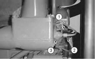
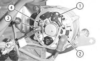
Disconnect wires (1), (2), (3), and (4) .
2
.
Illustration
g00642963
3.
Illustration
g00642965
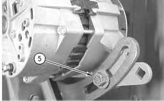
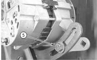
4. Remove bolt (5)
Illustration 3
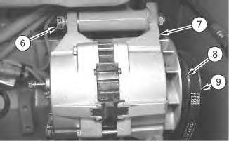
5. Loosen the nut and bolt (6) .
6. Slide alternator (7) toward the engine.
7. Remove belts (8) and (9) from the alternator.
8. Remove the nut and bolt (6) .
9. Remove alternator (7) .
Installation Procedure
Accidental machine starting can cause injury or death to personnel working on the machine.
To avoid accidental machine starting, turn the battery disconnect switch to the OFF position and remove the key. If the machine is not equipped with a battery disconnect switch, disconnect the battery cables from the battery and tape the battery clamps.
Place a do not operate tag at the battery disconnect switch location to inform personnel that the machine is being worked on.
Note: Put identification marks on all wires for installation purposes.
Illustration 4
1. Place alternator (7) in position.
2. Install the nut and bolt (6) but do not tighten the nut and bolt (6) .
3. Install belts (8) and (9) .
Illustration 5
4. Install bolt (5), but do not tighten bolt (5) .
5. Slide alternator (7) away from the engine in order to tension the belts.
Note: Refer to Operation and Maintenance Manual, SEBU7265, "V-beltsInspect/Adjust/Replace" for the 924G Wheel Loader or refer to Operation and Maintenance Manual, SEBU7266, "V-belts - Inspect/Adjust/Replace" for the 924Gz Wheel Loader.
6. Tighten bolts (5) and (6) .
g00642967
g00642965
6
7. Connect wire (1). Tighten to a torque of 1.70 ± 0.25 N·m (15 ± 2 lb in).
8. Connect wire (2) .
9. Connect wire (3). Tighten to a torque of 3.6 ± 0.8 N·m (32 ± 7 lb in).
10. Connect wire (4). Tighten to a torque of 2.25 ± 0.25 N·m (20 ± 2 lb in).
11. Close the left door.
12. Turn the battery disconnect switch to the ON position.
End By: Separate the steering frame lock. Refer to Disassembly and Assembly, "Steering Frame Lock - Separate and Connect" for the proper procedure.
Product: WHEEL LOADER
Model: 924G WHEEL LOADER AAN
Configuration: 924G and 924Gz Wheel Loader AAN00001-UP (MACHINE) POWERED BY 3056 Engine
Disassembly and Assembly
924G and 924Gz Wheel Loaders Engine Supplement
Electric Starting Motor - Remove and Install
SMCS - 1453-010
Removal Procedure
Start By:
i01203879
A. Connect the steering frame lock. Refer to Disassembly and Assembly, "Steering Frame LockSeparate and Connect" for the proper procedure.
Accidental machine starting can cause injury or death to personnel working on the machine.
To avoid accidental machine starting, turn the battery disconnect switch to the OFF position and remove the key. If the machine is not equipped with a battery disconnect switch, disconnect the battery cables from the battery and tape the battery clamps.
Place a do not operate tag at the battery disconnect switch location to inform personnel that the machine is being worked on.
1. Turn the battery disconnect switch to the OFF position.
2. Open the left door.
Illustration 1
2
.
g00643794
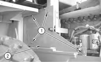
3. Remove four bolts (1) .
Illustration
g00643804
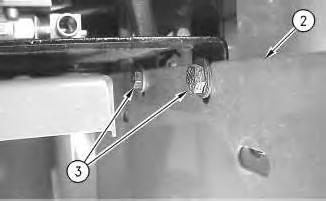
4. Loosen two bolts (3) on the top of panel (2) .
5. Remove panel (2)
7.
8.
9.
3
4
.
.
.
Illustration
g00643809
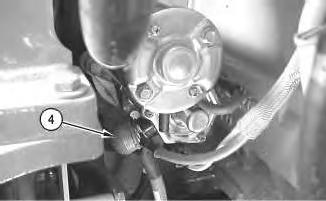
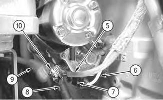
6. Slide back boot (4).
Illustration
g00643844
Remove nut (10)
Open the cap, and loosen screw (7)
Disconnect wires (5), (6), (8), and (9)
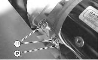
Illustration 5
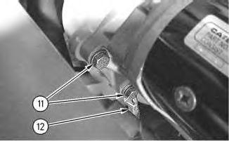
10. Remove two bolts (11) .
11. Disconnect wire (12) .
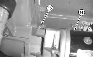
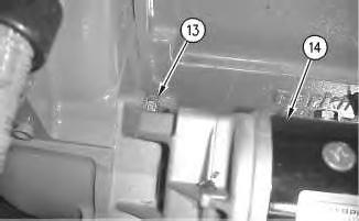
Illustration 6
12. Remove bolt (13) .
13. Remove electric starting motor (14) .
Installation Procedure
Accidental machine starting can cause injury or death to personnel working on the machine.
g00643854
g00643860
To avoid accidental machine starting, turn the battery disconnect switch to the OFF position and remove the key. If the machine is not equipped with a battery disconnect switch, disconnect the battery cables from the battery and tape the battery clamps.
Place a do not operate tag at the battery disconnect switch location to inform personnel that the machine is being worked on.
7
1. Place electric starting motor (14) in position.
2. Install bolt (13) .
8
3. Connect wire
.
Illustration
g00643860
Illustration
g00643854
(12)
4. Install two bolts (11) .
Illustration 9
5. Connect wires (5), (6), (8), and (9) .
6. Tighten screw (7) and close the cap.
7. Install nut (10) to a torque of 21.0 ± 3.5 N·m (186 ± 31 lb in).
10
8. Slide boot (4) over the connection.
g00643844
Illustration
g00643809
Illustration 11
9. Place panel (2) in position.
10. Tighten two bolts (3) .
Illustration 12
11. Install four bolts (1) .
12. Close the left door.
13. Turn the battery disconnect switch to the ON position.
End By: Separate the steering frame lock. Refer to Disassembly and Assembly, "Steering Frame Lock - Separate and Connect" for the proper procedure.
g00643804
g00643794
Product: WHEEL LOADER
Model: 924G WHEEL LOADER AAN
Configuration: 924G and 924Gz Wheel Loader AAN00001-UP (MACHINE) POWERED BY 3056 Engine
Disassembly and Assembly
924G and 924Gz Wheel Loaders Engine Supplement
Engine, Torque Converter and Transmission - Install
SMCS - 1004-012
Installation Procedure
Table 1 Required Tools
Fuel leaked or spilled onto hot surfaces or electrical components can cause a fire. To help prevent possible injury, turn the start switch off when changing fuel filters or water separator elements. Clean up fuel spills immediately.
i01237709
Care must be taken to ensure that fluids are contained during performance of inspection, maintenance, testing, adjusting and repair of the product. Be prepared to collect the fluid with suitable containers before opening any compartment or disassembling any component containing fluids.
Refer to Special Publication, NENG2500, "Caterpillar Tools and Shop Products Guide" for tools and supplies suitable to collect and contain fluids on Caterpillar products.
Dispose of all fluids according to local regulations and mandates.
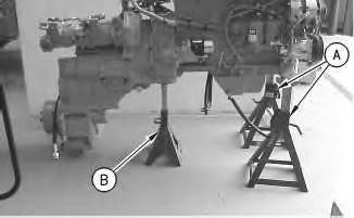
1. Use Tooling (A) and (B) in order to support the engine and the transmission. The weight of the engine and the transmission is 1179 kg (2600 lb).
Illustration 1
g00659869
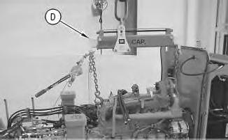
Illustration 2
g00659411
2. Use Tooling (D) and a suitable lifting device and carefully install the engine and the transmission on the machine. Be sure not to catch on any loose wires or loose hoses.
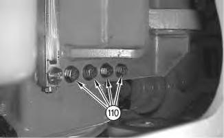
Illustration 3
g00659775
3. Install four bolts (110) and the washers in order to install the mounting bracket.
Illustration 4
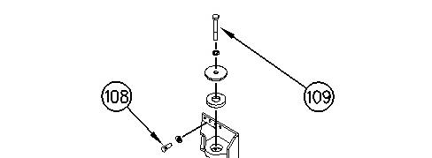
4. Install four bolts (108) and the washers.
g00659763
Illustration 5 g00668988
5. Install mounting bolt (109) and the mount assembly.
6
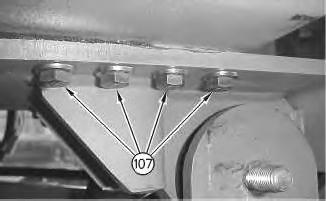
6. Install four bolts (107) and the washers in order to install the mounting bracket.
Illustration
g00659751
7
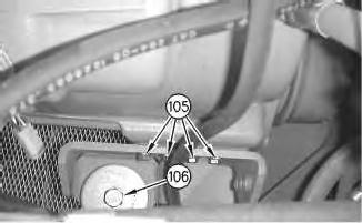
7. Install four bolts (105) and the washers.
8. Install mounting bolt (106), the washer, and the mount assembly.
8
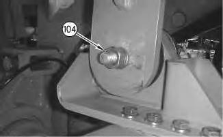
9. Install nut (104) and the washer.
Illustration
g00659571
Illustration
g00659549
This is the sample of the manual click on the download link for complete manual