

Product: BACKHOE LOADER
Model: 432E BACKHOE LOADER JBA
Configuration: 432E Backhoe Loader JBA00001-UP (MACHINE) POWERED BY C4.4 Engine
Disassembly and Assembly
422E, 428E, 432E, 434E, 442E and 444E Backhoe Loaders Engine Supplement
i03162190
Air Cleaner - Remove and Install
SMCS - 1051-010
Removal Procedure
1. Open the engine hood.
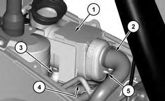
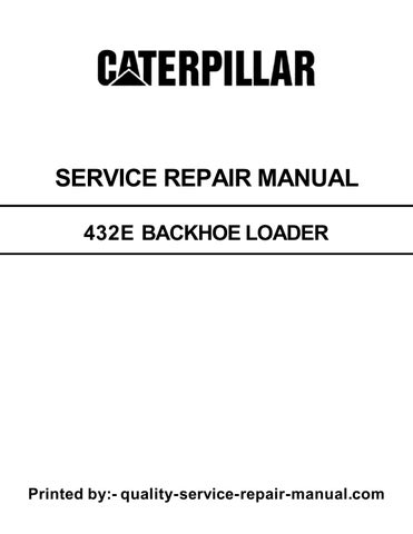
Illustration 1 g01621950
2. Disconnect hoses (2), (3), and (5) .
3. Remove bolts (4) and air cleaner assembly (1) .
Installation Procedure
Illustration 2
1. Install air cleaner assembly (1) and bolts (4) .
2. Connect hoses (2), (3), and (5) .
3. Close the engine hood.
Copyright 1993 - 2024 Caterpillar Inc. All Rights Reserved. Private Network For SIS Licensees.
Mon Sep 9 23:26:57 UTC+0530 2024
Product: BACKHOE LOADER
Model: 432E BACKHOE LOADER JBA
Configuration: 432E Backhoe Loader JBA00001-UP (MACHINE) POWERED BY C4.4 Engine
Disassembly and Assembly
422E, 428E, 432E, 434E, 442E and 444E Backhoe Loaders Engine Supplement
Alternator - Remove and Install
SMCS - 1405-010
Removal Procedure
Start By:
A. Remove the right side engine panel. Refer to Disassembly and Assembly, "Side PanelRemove and Install".
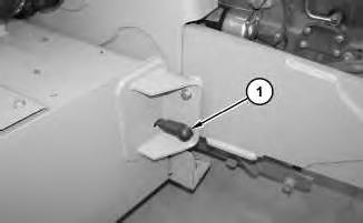
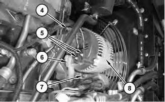
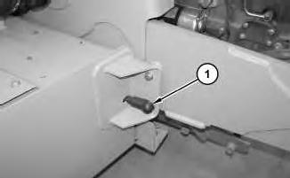
Illustration 1 g01114620
1. Disconnect ground cable assembly (1) in order to disconnect the batteries.
i03164644
2
2. Release the tension on belt tensioner (3) in order to position belt (2) out of the way.

3
3. Disconnect cable assembly (6) .
4. Disconnect harness assemblies (5) .
5. Remove bolt (4) and bolt (7). Remove alternator (8) .
Installation Procedure
This is the sample of the manual Click on the download link for complete Manual
4
1. Position alternator (8). Install bolts (7) and (8). Tighten bolts (7) and (8) to a torque of 22 N·m (16 lb ft).
2. Connect harness assemblies (5). Tighten the nuts for harness assemblies (5) to a torque of 4.5 ± 0.5 N·m (39.8 ± 4.4 lb in).
3. Connect cable assembly (6). Tighten the nut for cable assembly (6) to a torque of 7.8 ± 2.0 N·m (69.0 ± 17.7 lb in).
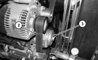
Illustration 5
4. Rotate belt tensioner (3) in order to install belt (2) .
5. Connect ground cable assembly (1) in order to connect the batteries.
End By: Install the right side engine panel. Refer to Disassembly and Assembly, "Side PanelRemove and Install".
Copyright 1993 - 2024 Caterpillar Inc. All Rights Reserved. Private Network For SIS Licensees. Mon Sep 9 23:26:29 UTC+0530 2024
Product: BACKHOE LOADER
Model: 432E BACKHOE LOADER JBA
Configuration: 432E Backhoe Loader JBA00001-UP (MACHINE) POWERED BY C4.4 Engine
Disassembly and Assembly
422E, 428E, 432E, 434E, 442E and 444E Backhoe Loaders Engine Supplement
Battery - Remove and Install
SMCS - 1401-010
Removal Procedure
Personal injury can result from failure to disconnect the battery.
First, disconnect the negative battery cable. Then, disconnect the positive battery cable.
A positive power lead can cause sparks if the battery is not disconnected. Sparks can possibly result in battery explosion or fire.
i03566894
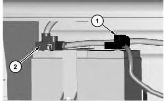
Illustration 1
g01889657
1. Disconnect the negative cable assembly (1). Disconnect the positive cable assembly (2) .
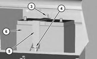
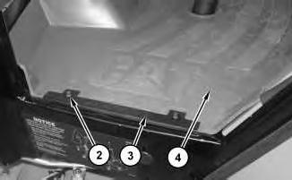
Illustration 2
g01889659
2. Remove bolts (4) and (4). Remove bracket (5). Remove battery (6) .
Installation Procedure
1. Install the battery (6) in the reverse order of removal.
a. Torque bolt (4) to a torque of 18.5 ± 1 N·m (14 ± 0.74 lb ft).
Copyright 1993 - 2024 Caterpillar Inc. All Rights Reserved. Private Network For SIS Licensees. Mon Sep 9 23:26:07 UTC+0530 2024
Product: BACKHOE LOADER
Model: 432E BACKHOE LOADER JBA
Configuration: 432E Backhoe Loader JBA00001-UP (MACHINE) POWERED BY C4.4 Engine
Disassembly and Assembly
422E, 428E, 432E, 434E, 442E and 444E Backhoe Loaders Engine Supplement
i03375640
Electric Starting Motor - Remove and Install
SMCS - 1453-010
Removal Procedure
Start By:
A. Remove the right side panel. Refer to Disassembly and Assembly, "Side Panel - Remove and Install".
Illustration 1 g01114620
1. Disconnect ground cable assembly (1) from the right side of the machine.
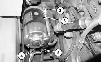
2
2. Disconnect harness assemblies (4). Disconnect harness assemblies (5). Remove nuts (2) and electric starting motor (3) .
Installation Procedure
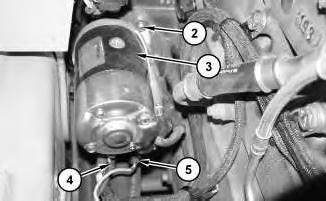
3
1. Install electric starting motor (3). Install nuts (2). Connect harness assembly (4). Connect harness assemblies (5).
4
2. Connect ground cable assembly (1) .
End By: Install the right side panel. Refer to Disassembly and Assembly, "Side Panel - Remove and Install".
Copyright 1993 - 2024 Caterpillar Inc. All Rights Reserved.
Private Network For SIS Licensees.
Mon Sep 9 23:26:16 UTC+0530 2024
Product: BACKHOE LOADER
Model: 432E BACKHOE LOADER JBA
Configuration: 432E Backhoe Loader JBA00001-UP (MACHINE) POWERED BY C4.4 Engine
Disassembly and Assembly
422E, 428E, 432E, 434E, 442E and 444E Backhoe Loaders Engine Supplement
i03165915
Engine - Install SMCS - 1000-012
Installation Procedure
Table 1 Required Tools
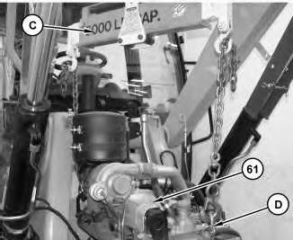
Illustration 1
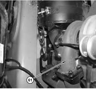
Illustration 2
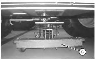
1. Attach Tooling (A), Tooling (B), and a suitable lifting device to engine (61). The weight of engine (61) is approximately 454 kg (1000 lb). Use Tooling (A), Tooling (B), and the suitable lifting device in order to position engine (61) into the machine.
3
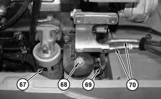
2. Install mounting bolts (68) to each side of the engine.
3. Position tube assemblies (70) and connect clips (69) .
4. Use Tooling (A) in order to install engine oil filter (67). Refer to Operation and Maintenance Manual, "Engine Oil and Filter - Change".
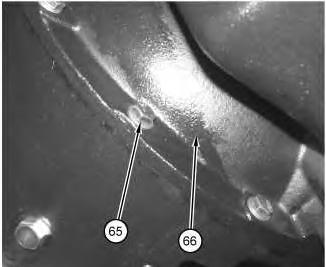
Illustration 4 g01527055
5. Install bolts (65) into bell housing (66) .
Note: Be sure to connect the ground wires (not shown) and the ground cable (not shown) during the installation of bolts (65) .
5
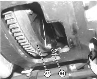
6. Install bolts (64) into flywheel (63). Tighten bolts (64) to a torque of 55 ± 5 N·m (41 ± 4 lb ft).
Note: The engine must be manually rotated in order to access all bolts (64) .
6
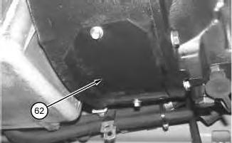
7. Install access panel (62) .
7
8. Remove Tooling (B) from the transmission.
8
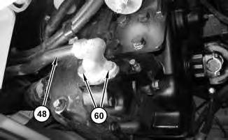
9. Position tube assembly (48) and install bolts (60) .
9
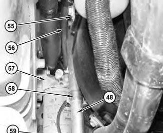
This is viewed from the bottom of the machine.
10. Install clip (59) .
11. Install clip (58) onto tube assembly (48) .
12. Install fuel filter and base (57) .
13. Connect hose (56) and install clip (55) .
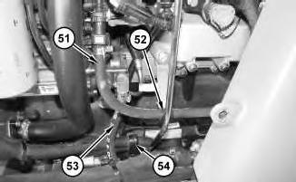
15. Connect hoses (53) and (51) .
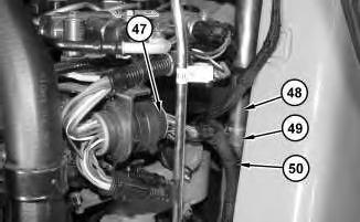
Illustration 11
g01526964
16. Install clip (49) and install cable straps (50) to tube assembly (48) .
17. Connect harness assembly (47) .
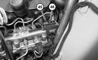
Illustration 12
g01526956
18. Connect cable assembly (46) and install nut (45) .
13
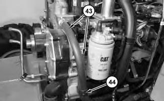
19. Connect hoses (43) and connect clip (44) .
14
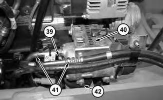
20. Position refrigerant compressor (40) and hose assemblies (41). Install bolts (42) .
21. Position the clamp and install bolt (39) in order to connect hose assemblies (41) .
15
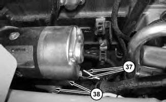
22. Connect harness assemblies (37) to the starter. Tighten the nuts for harness assemblies (37) to a torque of 3.50 ± 0.25 N·m (31 ± 2 lb in).
23. Connect cable assemblies (38) to the starter. Tighten the nut that secures cable assemblies (38) to a torque of 21 ± 4 N·m (15 ± 3 lb ft).
16
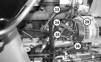
24. Connect cable assembly (35) .
25. Connect harness assembly (29) .
26. Attach cable straps (33) in order to secure harness assembly (29) .
27. Connect harness assembly (36) .
28. Connect harness assemblies (34). Tighten the nuts that secure harness assemblies (34) to a torque of 4.5 ± 0.5 N·m (39.8 ± 4.4 lb in).
17
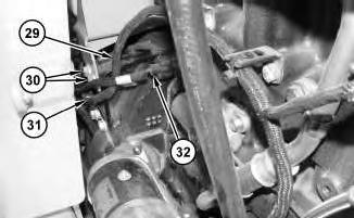
29. Install bolts (30). Repeat this step for the opposite side.
30. Attach cable strap (31) in order to secure harness assembly (29) .
31. Connect harness assembly (32) .
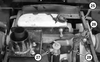
18
32. Install clip (28) .
33. Install bolt (27) .
34. Use two people in order to position frame assembly (25). The weight of frame assembly (25) is approximately 29 kg (65 lb). Install bolts (26) .
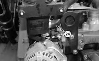
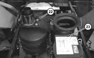
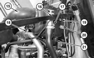
Illustration 21
37. Install bolts (19) .
38. Connect clip (20) .
39. Connect hose (21) .
40. Position the tube assembly and install bolt (17) .
41. Connect harness assembly (18) and attach cable straps (16) .
42. Install hose (15) .
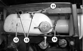
43. Attach cable strap (14). Connect hoses (11) to tank (12). Connect harness assemblies (13) to tank (12) .
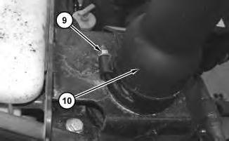
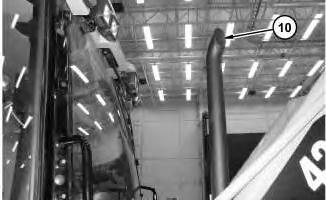
44. Position exhaust pipe (10) to the correct orientation with the cab. Position the clamp against the mounting bracket. Orient the clamp toward the cab. Install nut (9). Tighten nut (9) to a torque of 55 ± 10 N·m (41 ± 7 lb ft).
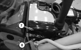
45. Install cover (7) and install bolts (8) .
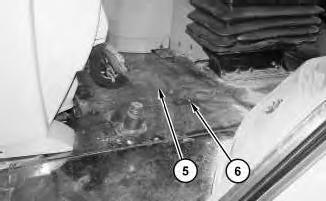
46. Position plate (5) and install bolts (6) .
47. Position floor mat (4). Position plate (3) and install bolts (2). Position plate (3) and install bolts (2) on the opposite side of the cab.
48. Connect ground cable assembly (1) in order to connect the batteries.
49. Fill the transmission with oil. Refer to Operation and Maintenance Manual, "Transmission OilChange".
End By: Install the radiator, the refrigerant condenser, the hydraulic oil cooler, and the transmission oil cooler. Refer to Disassembly and Assembly, "Radiator, Refrig Condenser, and Hyd and TMSN Oil Cooler - Install ".
Copyright 1993 - 2024 Caterpillar Inc. All Rights Reserved. Private Network For SIS Licensees.
This is the sample of the manual Click on the download link for complete Manual