

Product: BACKHOE LOADER
Model: 420E BACKHOE LOADER DAN
Configuration: 420E Backhoe Loader Parallel Lift
Disassembly and Assembly
416E, 420E and 430E Backhoe Loaders Power Train
Axle Housing (Differential and Bevel Gear) (Front) - Assemble
S/N - DAN1-UP
S/N - HLS1-UP
Assembly Procedure
1
L 8T-5096 Dial Indicator Gp 1
(1) Equal Size Tires (EST)
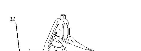
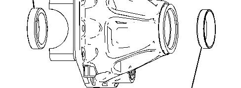

Illustration 1 g01040991
1. Use Tooling (E) and install bearing cups (32) and (33).
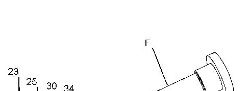
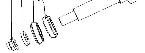

Illustration 2 g01241759
2. Install bearing cone (34) onto Tooling (F). Install Tooling (F). Install bearing cone (30), washer (25), and nut (23). Tighten nut (23) until there is no end play.
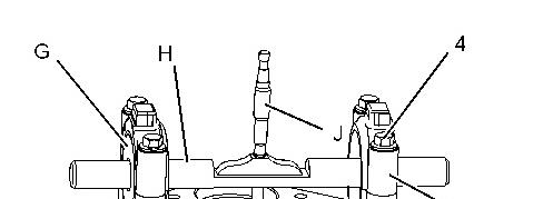
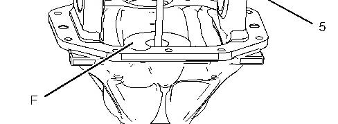

Illustration 3 g01041107
3. Install Tooling (G) and (H). Install caps (5) and bolts (4). Install Tooling (J).
4. Use Tooling (G), (H), and (J) to measure the distance to the pinion.
5. Measure the depth from Tooling (H) to the bottom of the hole in Tooling (F). Record the measurement as Measurement (X).
This is the sample of the manual Click on the download link for complete Manual
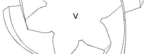

Illustration 4 g01027211
6. Measurement (V) is stamped on the head of pinion shaft (31). Measurement (S) is thickness of the shim that is used between pinion shaft (31) and bearing cone (33). Use the following formula in order to calculate Measurement (S): X mm - V mm = S mm
7. Among the available list of shims, choose the shim with the thickness of Measurement (S).
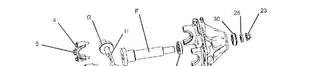
Illustration 5
g01241762
8. Remove bolts (4), caps (5), Tooling (G), and Tooling (H). Remove nut (23), washer (25), and bearing cone (30). Remove Tooling (F) and bearing cone (34).
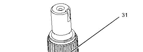
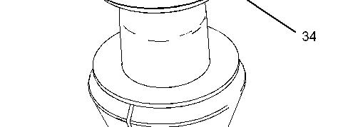

Illustration 6 g01041145
9. Install the suitable shim onto pinion shaft (31). Install the shim with the chamfer against the gear. Raise the temperature of bearing cone (34) and install bearing cone (34) onto pinion shaft (31).

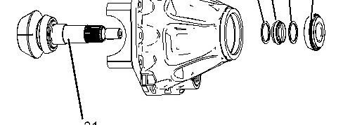

Illustration 7 g01040990
10. Install pinion shaft (31), washers (28), collapsible spacer (29), and bearing cone (30).
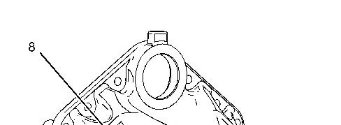
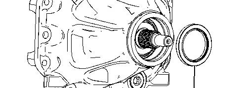

Illustration 8 g01040989
11. Install lip seal (27) into differential housing (8).
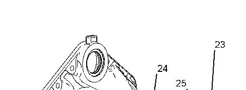
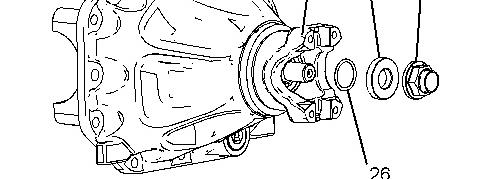

Illustration 9 g01041148
Note: Check the O-ring seal for wear or for damage. If necessary, replace the O-ring seal.
12. Install yoke (24). Install O-ring seal (26), washer (25), and nut (23).
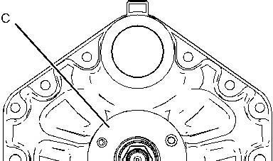
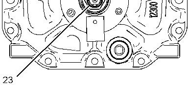
Illustration 10 g01041469
13. Use Tooling (C) with a dial type torque wrench in order to set the rotating torque. Tighten nut (23) in order to achieve a rotating torque between 1.81 N·m (16.0 lb in) and 2.60 N·m (23.0 lb in).
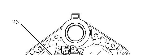
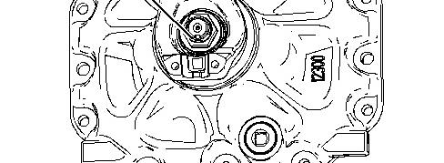

Illustration 11 g01040894
14. Use a suitable hammer and a punch and stake nut (23).
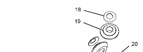
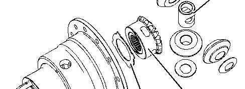
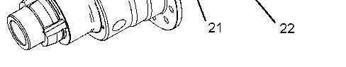
Illustration 12 g01040858
15. Install thrust washer (21) and side gear (22). Install spider (20), gears (19), and thrust washers (18).
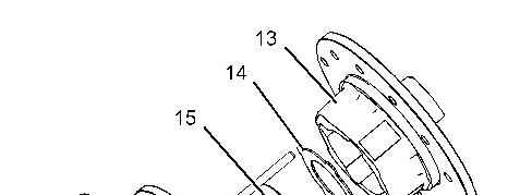
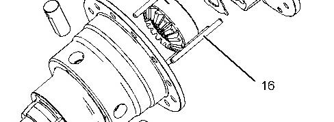

Illustration 13 g01040856
16. Install planetary shafts (17). Install locking pins (16). Install side gear (15) and thrust washer (14). Install cover (13).
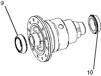
Illustration 14
g01041480
17. Raise the temperature of bearing cones (9) and (10). Install bearing cones (9) and (10).
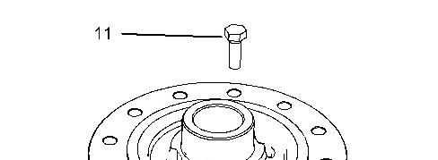
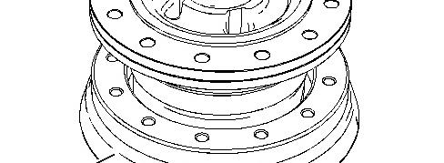

Illustration 15 g01040825
18. Install bevel gear (12) onto the differential. Apply Tooling (K) to the threads of bolts (11). Install bolts (11) and tighten bolts (11) to a torque of 70 N·m (52 lb ft).
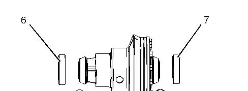
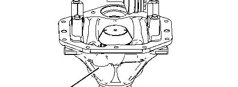

Illustration 16 g01040808
19. Install bearing cups (6) and (7) and install the differential into axle housing (8).
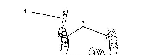
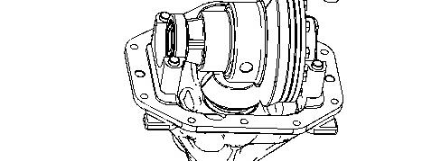

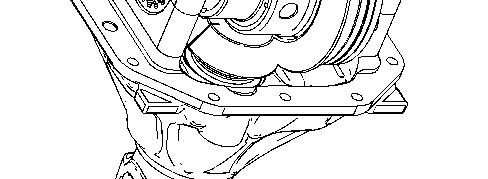
Illustration 17 g01040715
20. Install caps (5) and install bolts (4). Slightly tighten bolts (4). Do not torque bolts (4) at this time.
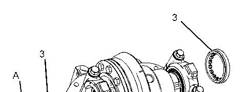
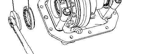

Illustration 18 g01034579
21. Use Tooling (A) and install spanner nuts (3).
22. Oscillate the pinion shaft and use Tooling (A) to advance spanner nuts (3) until there is slight backlash and no end play on the bearings.
Illustration 19 g01040894
23. Use a dial type torque wrench and measure the total rotating torque. Use the following formula in order to calculate the total rotating torque (TRT): P equals the rotating torque that was measured in Step 13. TRT = P + 0.3819 N·m (3.38 lb in) to P + 0.4406 N·m (3.90 lb in)
24. If the total rotating torque (TRT) is less than the specified amount, tighten the spanner nuts. If the total rotating torque (TRT) is greater than the specified amount, loosen the spanner nuts. Be sure to always maintain a slight backlash.
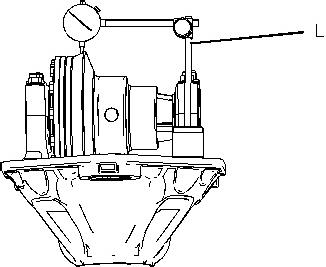

Illustration 20
25. Mount Tooling (L) onto the differential housing, as shown. Measure the backlash between the pinion and the bevel gear. The proper backlash setting is between 0.180 mm (0.0071 inch) and 0.230 mm (0.0091 inch).
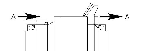
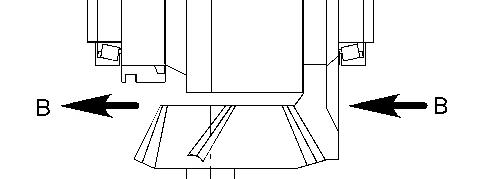

Illustration 21 g01029595
26. If the backlash is not within the specification, retract one spanner nut and advance the opposite spanner nut equally. This will maintain the bearing preload. If the backlash is less than the specified amount, move the bevel gear in Direction (A). If the backlash is greater than the specified amount, move the bevel gear in Direction (B).
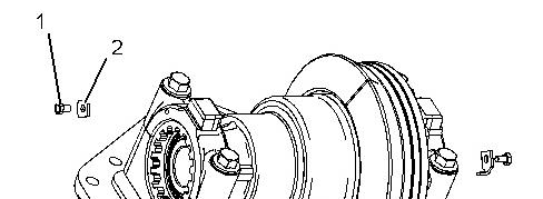

22 g01040713
27. Install retainers (2) and bolts (1). Tighten bolts (1) to a torque of 13 N·m (10 lb ft).
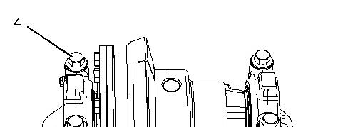
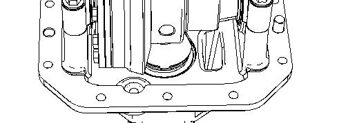

Illustration 23 g01034820
28. Tighten bolts (4) to a torque of 220 N·m (162 lb ft).
End By:
a. Install the front axle differential and bevel gear into the axle housing. Refer to Disassembly and Assembly, "Axle Housing (Differential and Bevel Gear) (Front) - Install".
Copyright 1993 - 2022 Caterpillar Inc. All Rights Reserved. Private Network For SIS Licensees. Wed Nov 2 12:13:16 UTC+0530 2022
Product: BACKHOE LOADER
Model: 420E BACKHOE LOADER DAN
Configuration: 420E Backhoe Loader Parallel Lift DAN00001-UP (MACHINE) POWERED BY C4.4 Engine
Disassembly and Assembly
416E, 420E and 430E Backhoe Loaders Power Train
Axle Housing (Differential and Bevel Gear) (Front) - Assemble
SMCS - 3256-016-FR; 3258-016-FR; 3260-016-FR
S/N - DAN1-UP
S/N - DJL1-UP
S/N - LMS1-UP
S/N - MXB1-UP
S/N - SWC1-UP
Assembly Procedure
Table 1 Required
NOTICE
Keep all parts clean from contaminants.
Contaminants may cause rapid wear and shortened component life.
Note: Cleanliness is an important factor. Before assembly, thoroughly clean all parts in cleaning fluid. Allow the parts to air dry. Do not use wiping cloths or rags to dry parts. Lint may be deposited on the parts which may cause trouble. Inspect all parts. If any parts are worn or damaged, use new parts for replacement. Dirt and other contaminants can damage the precision component. Perform assembly procedures on a clean work surface. Keep components covered and protected at all times.
Note: Check the O-ring seals, the gaskets, and the seals for wear or for damage. Replace the components, if necessary.
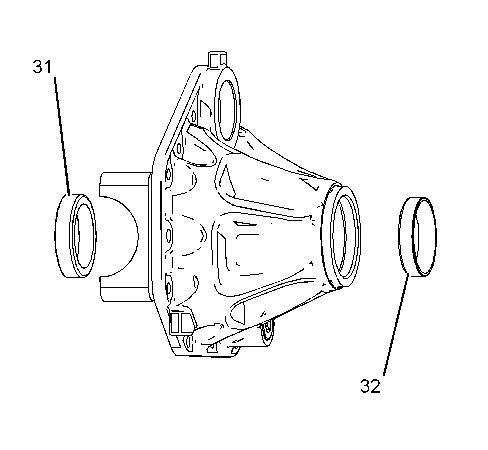
Illustration 1 g01517459
1. Use Tooling (E) in order to install bearing cups (31) and (32).
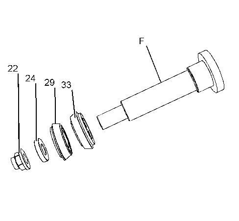
Illustration 2 g01517493
This is the sample of the manual Click on the download link for complete Manual