

Product: BACKHOE LOADER
Model: 416 BACKHOE LOADER 5PC
Configuration: 416 BACKHOE LOADER 5PC00001-06191 (MACHINE) POWERED BY T4.236 DIESEL ENGINE
Disassembly and Assembly BACKHOE LOADER ENGINE Media
SENR31290002
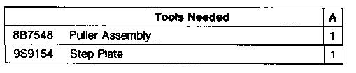
Alternator
SMCS - 1405-010; 1405-015; 1405-016
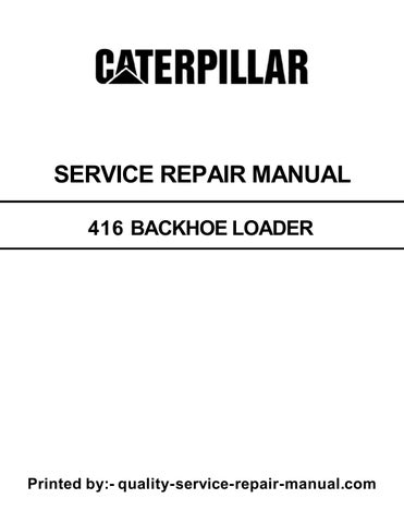
Remove And Install Alternator
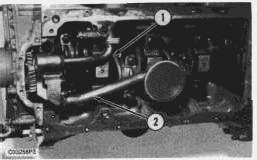
1. Loosen tension adjustment bolt (1), and remove fan belt (2).
2. Disconnect all the wires at rear of the alternator.
3. Remove the tension adjustment bolt (1).
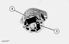
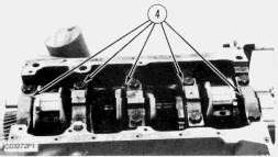
4. Remove mounting bolt (4) and alternator (3).
NOTE: Upon installation of the alternator, see Belt Tension for fan belt (2) in Specifications.
Disassemble Alternator
START BY:
a. remove alternator
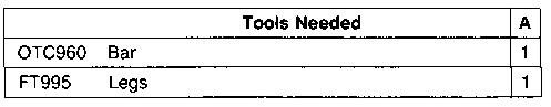
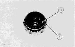
1. Remove nut (3), pulley (2) and fan (1) from the shaft.
2. Remove regulator assembly (4) and capacitor (5).
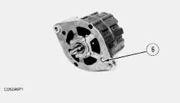
3. Remove screws (6), and separate the frame assemblies.
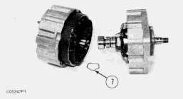
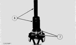
4. Remove wave washer (7).
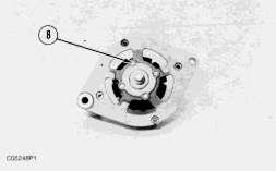
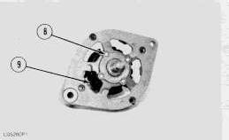
5. Remove screws (8), and separate the frame assembly from the rotor.
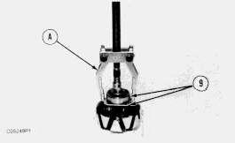
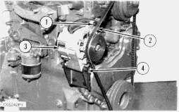
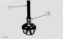
6. Install tooling (A) on cover and large bearing (9), and remove them from the rotor shaft.
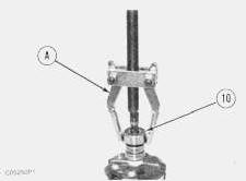
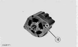
7. Use tooling (A) to remove small bearing (10) from the shaft.
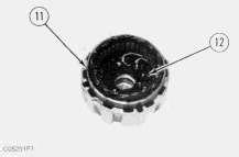
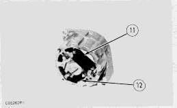
8. Remove screws (12) to remove stator (11) from frame assembly.
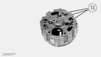
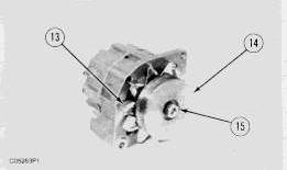
9. Remove terminals (13) and insulators from the frame assembly.
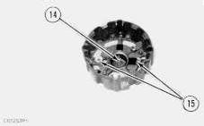
10. Remove bearing (14) and insulators(15) from the frame assembly.
Assemble Alternator
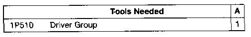
1. Install terminals (1) on the frame assembly.
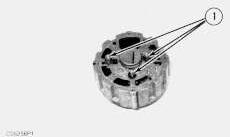
2. Install bearing (2) and insulators(3).
3. Put stator (5) in position in the frame assembly with screws (4).
4. Install small bearing (6) on rotor shaft with tool group (A).
5. Install cover and bearing (7) on the shaft with tool group (A) and a suitable sleeve.
6. Install frame assembly on rotor (9) with screws (8).
7. Connect the frame assemblies together with screws(10).
8. Install regulator assembly (11) and capacitor (12).
9. Install fan (13), pulley (14) and nut (15) on the shaft.
END BY:
a. install alternator
Product: BACKHOE LOADER
Model: 416 BACKHOE LOADER 5PC
Configuration: 416 BACKHOE LOADER 5PC00001-06191 (MACHINE) POWERED BY T4.236 DIESEL ENGINE
Disassembly and Assembly BACKHOE LOADER ENGINE
Media Number -SENR3129-00
Date -01/02/1986
Camshaft and Camshaft Bearing
SMCS - 1210; 1211-012; 1211-011
Remove Camshaft And Camshaft Bearing
START BY:
a. remove rocker shaft and push rods
b. remove timing gear case
c. remove oil pan
d. remove fuel pump
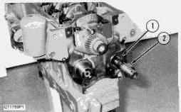
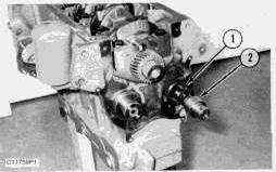
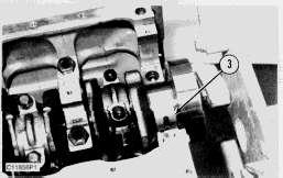
1. Remove thrust washer (1).
Updated -08/03/2006
SENR31290030
2. Push the valve lifters toward the cylinder head, and hold them in this position.
3. Remove camshaft (2) from the engine block. Turn the camshaft while removing it.
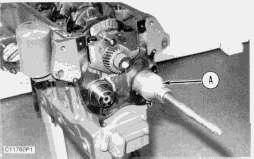
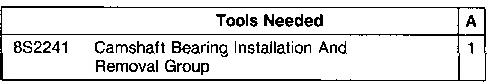
4. If bearing removal is necessary, remove the bearing with tooling (A).
Install Camshaft and Camshaft Bearing
NOTICE
Make an alignment of the oil holes in the bearing with the oil holes in the engine block.
1. Install a new camshaft bearing with tooling (A).
2. Put 2P2506 Lubricant on the camshaft lobes and cam follower faces. Put clean engine oil on the bearing journals of the camshaft.
3. Install camshaft (2).
This is the sample of the manual Click on the download link for complete Manual
4. Install thrust washer (1). Make an alignment of the hole in the washer and the dowel in the block.
END BY:
a. install fuel pump
b. install oil pan
c. install timing gear case
d. install rocker shaft and push rods Copyright 1993 - 2020 Caterpillar Inc. All Rights Reserved. Private Network For SIS Licensees.
Product: BACKHOE LOADER
Model: 416 BACKHOE LOADER 5PC
Configuration: 416 BACKHOE LOADER 5PC00001-06191 (MACHINE) POWERED BY T4.236 DIESEL ENGINE
Disassembly and Assembly BACKHOE LOADER ENGINE Media
Connecting Rod Bearings
SMCS - 1219-010
Remove And Install Connecting Rod Bearings
START BY:
a. remove oil pan
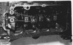
1. Remove tube and elbow (1).
2. Remove tube and oil sump (2).
Updated -08/03/2006
SENR31290023
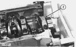
3. Turn the crankshaft until two of the pistons are at top center and two are at bottom center.
NOTICE
Put identification markson the connecting rod caps as to their location in the engine. Keep the caps with their respective piston.
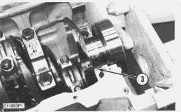
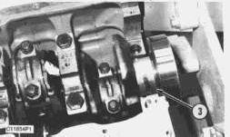
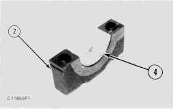
4. Remove nuts (3), and remove connecting rod bearing cap (4).
5. Remove the lower bearing half from the connecting rod cap. Push the connecting rod away from the crankshaft, and remove the upper bearing half.
NOTICE
Use tape to holdthe bearing halves together andto identify the number of the cylinder.
6. Install the upper bearings in the connecting rods. Be sure the tab on the back of the bearing fits in the groove of the connecting rod.
NOTE: Install the connecting rod bearingsdry when the clearance checks are made. Put clean engine oil on the connecting rod bearings for final assembly.
7. Carefully pull the connecting rodsonto the crankshaft.
8. Install the lower bearings in the connecting rod caps. Be sure the tab on the back of the bearing fits the groove of the cap.
9. Check the bearing clearance with Plastigage as follows:
a. Put clean oil on the connecting rod bolt threads.
b. Align the number on bearing cap (4) with the number on the connecting rod, and install bearing cap (4) with a line of Plastigage acrossthe bearing.
c. Install the nutsfinger tight; then tighten them to a torque of 100 N·m (75 lb.ft.).
d. Remove the connecting rod cap, and measure the thickness of the Plastigage to the bearing clearances. See Engine Specifications for correct bearing clearances.
e. Carefully move the connecting rod up enough to permit clean egnine oil to be put on the upper bearing and crankshaft journal.
f. Carefully pull the connecting rod onto the crankshaft.
g. Install connecting rod cap (4), and tighten the nuts to a torque of 100 N·m (75 lb.ft.).
h. Repeat the procedure for the remainder of the connecting rods.
10. Install tube and elbow (1) and tube and oil sump (2).
END BY:
a. install oil pan
Product: BACKHOE LOADER
Model: 416 BACKHOE LOADER 5PC
Configuration: 416 BACKHOE LOADER 5PC00001-06191 (MACHINE) POWERED BY T4.236 DIESEL ENGINE
Disassembly and Assembly BACKHOE LOADER ENGINE
Media Number -SENR3129-00
Date -01/02/1986
Crankshaft Main Bearings
SMCS - 1203-010
Remove And Install Crankshaft Main Bearings
START BY:
a. remove engine and transmission
b. remove oil pump
c. remove crankshaft rear seal
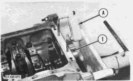
1. Fasten the engine to tool (A) at the flywheel end as shown.
2. Remove bridge (1) and the seals.
Updated -08/03/2006
SENR31290036
3. Remove rear main bearing cap (2).
NOTE: Be sure the location is marked on the main bearing cap before it is removed. The stamped location number is toward the camshaft.
4. Remove upper bearing half (3) with an approved bearing removal tool.
NOTICE
Do not turn the crankshaft ina counterclockwise direction because the tab of the bearing can be pushed between the crankshaft and the engine block. This will cause damage to the crankshaft and engine block.
5. Turn the crankshaft clockwise asseen from the flywheel to remove bearing upper half (3).
6. Remove bearing lower half (4) from rear main bearing cap (2).
7. Put the bearing upper half (3) in position on the crankshaft, and use the removal tool to rotate the bearing into position. Turn the crankshaft in a counterclockwise direction to engage bearing tab with the engine block.
8. Install the bearing lower half in the main bearing cap.
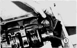
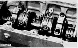
9. Put a piece of Plastigage (5) acrossthe crankshaft main bearing face.
NOTE: Install main bearings dry when the clearance checks are made. Put clean engine oil on the main bearings for final assembly.
10. Put the main bearing cap in position. Put clean engine oil on the threads of the main bearing cap bolts, and tighten them finger tight.
11. Tighten the main bearing cap bolts to a torque of 245 N·m (180 lb.ft.).
12. Remove the bearing cap, and measure the thicknessof the Plastigage to determine the bearing clearance. See Engine Specifications for the correct bearing clearance.
13. Remove the bearing upper half.
14. Put clean engine oil on the bearing upper half, and install it.
15. Put clean engine oil on the bearing lower half, and install the main bearing cap.
16. Tighten the main bearing cap bolts to a torque of 245 N·m (180 lb.ft.).
17. Repeat Steps 3 through 16 for the other main bearings, except the center main bearing.
18. Remove the center main bearing cap, and remove thrust washer (6) from each side of the center main bearing location in the cylinder block.
19. Remove the thrust washers from each side of the main bearing cap.
20. Repeat Steps 4 through 12 to determine the center main bearing clearance.
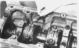
21. Install newthrust washers (6) on each side of the center main bearing location in the engine block. Be sure the bearing surface is toward the crankshaft, and the smooth surface is toward the engine block.
22. Put clean engine oil on the thrust washers.

23. Put newthrust washers(6) on the side of the main bearing cap. Be sure the tabs on the thrust washers are engaged with the grooves in the main bearing cap.
24. Install the center main bearing cap and thrust washer. Be careful the thrust washers do not come out of position.
25. Tighten the main bearing cap bolts to a torque of 245 N·m (180 lb.ft.).
26. Measure the crankshaft end play. See Engine Specifications for the correct end play dimension.
27. Install bridge and seals on the cylinder block.
END BY:
a. install crankshaft rear seal
b. install oil pump
c. install engine and transmission
1993 - 2020 Caterpillar Inc.
Network For SIS Licensees. Fri Jan 3 18:49:42 UTC+0530 2020
Product: BACKHOE LOADER
Model: 416 BACKHOE LOADER 5PC
Configuration: 416 BACKHOE LOADER 5PC00001-06191 (MACHINE) POWERED BY T4.236 DIESEL ENGINE
Disassembly and Assembly
BACKHOE LOADER ENGINE
Media Number -SENR3129-00
Crankshaft Pulley
SMCS - 1205-011; 1205-012
Remove Crankshaft Pulley
Date -01/02/1986
Updated -08/03/2006
SENR31290026
START BY:
a. remove fan assembly
b. remove radiator
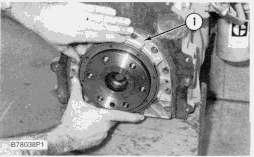
1. Thoroughly clean the area behind the crankshaft pulley so dirt does not enter the engine after the crankshaft pulley isremoved.
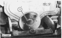
2. Remove bolt (1) and the washer.
Example
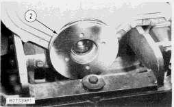
3. Remove crankshaft pulley (2).
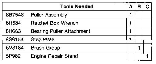
NOTE: If pulley removal cannot be done by hand, use tool (A) to remove the pulley. Be sure to use the step plate [part of tool (A)] so the threads in the crankshaft are not damaged.
4. Inspect the crankshaft front oil seal.
Install Crankshaft Pulley
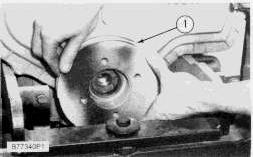
Example
1. Align the timing marks on the crankshaft pulley with the timing markson the crankshaft. Install crankshaft pulley (1) onto the crankshaft.
2. Install bolt (2) and the washer. Tighten the bolt to a torque of 410 N·m (300 lb.ft.).
END BY:
a. install radiator
b. install fan assembly Copyright 1993 - 2020 Caterpillar Inc. All Rights Reserved. Private Network For SIS Licensees. Fri Jan 3 18:47:12 UTC+0530 2020
Product: BACKHOE LOADER
Model: 416 BACKHOE LOADER 5PC
Configuration: 416 BACKHOE LOADER 5PC00001-06191 (MACHINE) POWERED BY T4.236 DIESEL ENGINE
Disassembly and Assembly
BACKHOE LOADER ENGINE
Updated -08/03/2006
SENR31290035
Crankshaft Rear Seal
SMCS - 1161-011; 1161-012
Remove Crankshaft Rear Seal
START BY:
a. remove flywheel housing
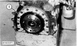
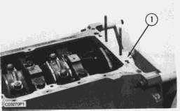
1. Remove the boltsand socket head screws that hold oil seal housing (1) to the engine block.
2. Move the oil seal housing off the dowels, and remove the gasket.
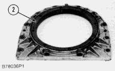
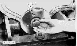
3. Remove crankshaft rear seal (2) from the seal housing.
Install Crankshaft Rear Seal
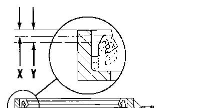

1. Check the flange of the crankshaft for a wear groove. If a wear groove exists, install the new seal in the housing until dimension (X) is 3.18 mm (.125"). If there are two wear groovesin the flange, install the seal in the housing to a depth of 6.35 mm (.250 in.) - dimension (Y).
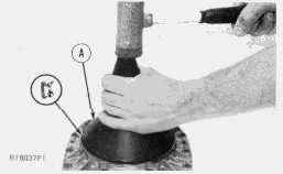
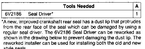
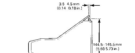
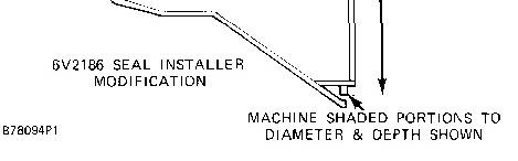
2. Use tool (A) to install the crankshaft rear seal into the seal housing. Be sure the spring loaded lip is toward the inside of the seal housing. The seal surface must be clean and dry. Do not handle the lip of the seal.
3. Put the gasket in position on the dowels.
4. Put seal housing (1) in position on the dowels.
5. Install the boltsand socket head screws to hold the seal housing in position.
END BY:
a. install flywheel housing
Product: BACKHOE LOADER
Model: 416 BACKHOE LOADER 5PC
Configuration: 416 BACKHOE LOADER 5PC00001-06191 (MACHINE) POWERED BY T4.236 DIESEL ENGINE
Disassembly and Assembly BACKHOE LOADER ENGINE
Media Number -SENR3129-00 Publication Date -01/02/1986 Date Updated -08/03/2006
SENR31290037
Crankshaft
SMCS - 1202-011
Remove Crankshaft
START BY:
a. remove engine
b. remove crankshaft rear seal
c. remove oil pump
1. Install the engine on tool (C). Fasten it in position at the flywheel end as shown.
2. Remove bridges (1) and the seals.
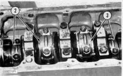
3. Remove connecting rod bearing caps (2) and (3). Be sure the connecting rods, connecting rod caps and bearings are labeled so the partscan be matched at assembly.
NOTE: Be sure the location is marked on the main bearing caps before they are removed. The stamped location number is toward the camshaft.
4. Remove five main bearing caps(4). Remove the bearings from the main bearing caps, and remove the thrust washers from the center main bearing cap. Put identification markson the bearings as to their location in the engine.
5. Remove the connecting rod bolts, and push the pistons to the top of their stroke. Do not damage the crankshaft journals with the connecting rod bolts.
This is the sample of the manual Click on the download link for complete Manual