

Previous Screen
Product: EXCAVATOR
Model: 349E EXCAVATOR RGH
Configuration: 349E & 349E L Excavators RGH00001-UP (MACHINE) POWERED BY C13 Engine
Disassembly and Assembly
349E Excavator and 349E MHPU
Mobile Hydraulic Power Unit C13 Engine Supplement Media
Fan Drive - Assemble - Hydraulic Fan Drive
SMCS - 1359-016
Assembly Procedure
i06192451
1
A 1P-1861 Retaining Ring Pliers
B 9U-7480 Compressing Tube
C 1P-1859 Retaining Ring Pliers 1
D 1P-1863 Retaining Ring Pliers 1
E - Loctite Flexible Anaerobic Gasket Flange 1
F - Loctite 648 1
G 359-4915 Driver 1
H 359-4916 Driver 1
Note: Caution is required while handling the lip seals. The lip seals can be damaged if objects or cleaning fluids contact the sealing surface.
Note: Cleanliness is an important factor. Before assembly, thoroughly clean all parts except the lip seals with cleaning fluid. Allow the parts to air dry. Wiping cloths or rags should not be used to dry parts. Lint may be deposited on the parts which may cause later trouble. Inspect all parts. If any parts are worn or damaged, use new parts for replacement.
Note: Check the O-ring seals, the gaskets, and the seals for wear or for damage. Replace the components, if necessary.
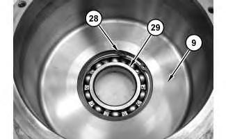
Illustration 1
g01333314
1. Use a suitable press to install bearing (29) into case (9) . Use Tooling (A) in order to install retaining ring (28) .
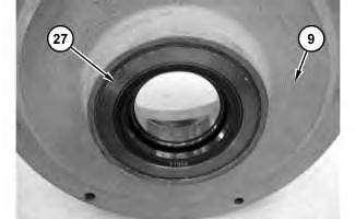
Illustration 2
g01333310
Note: Caution is required while handling the lip seals. The lip seals can be damaged if objects or cleaning fluids contact the sealing surface.
2. Apply Tooling (E) to the outside diameter of lip seal (27) . Carefully install lip seal (27) into case (9) .
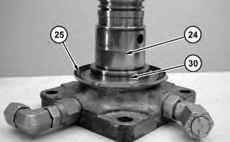
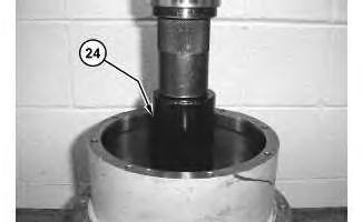
3. Install seal (25) onto shaft assembly (24) .
4. Apply Tooling (F) to the full diameter of the shoulder on shaft assembly (24) . Position new sleeve (30) on shaft assembly (24) . The external chamfer on sleeve (30) will be on top. Use Tooling (G) and a suitable press in order to install sleeve (30) . Remove excess Tooling (F) .
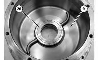
5. Position tube assembly (26) into case (9) .
6. Position case (9) and tube assembly (26) onto shaft assembly (24) .
7. Use a suitable press and a suitable driver to press shaft assembly (24) through the bearing and through tube assembly (26) .

6
8. Use Tooling (D) in order to install retaining ring (23) . Install seal rings (22) onto shaft assembly (24) .
7
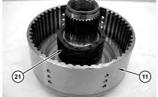
9. Install spring (21) on clutch housing assembly (11) .
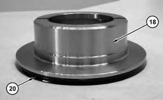
Illustration 8
10. Install seal (20) on piston (18) .

Illustration 9
g01333298
Improper assembly of parts that are spring loaded can cause bodily injury.
To prevent possible injury, follow the established assembly procedure and wear protective equipment.
11. Install piston (18) . Use Tooling (B) and a suitable press in order to position piston (18) . Use Tooling (C) in order to install retaining ring (19) . Carefully release the tension on Tooling (B) .
This is the sample of the manual
Click on the download link for complete Manual
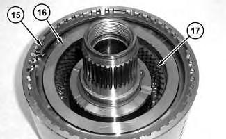
Illustration 10
g01208920
12. Install clutch plates (16) and discs (17) . Install retaining ring (15) .
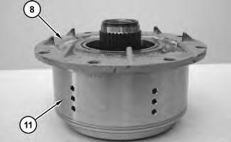
Illustration 11
g01209073
13. Position cover assembly (8) onto clutch housing assembly (11) .
Note: Make sure that the splines of cover assembly (8) fully engage all of the clutch plates and discs in the clutch assembly.
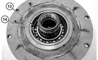
Illustration 12
13
g01258534
Note: Caution is required while handling the lip seals. The lip seals can be damaged if objects or cleaning fluids contact the sealing surface.
14. Use a suitable press in order to install bearing (14) . Use Tooling (A) in order to install retaining ring (13) . Install lip seal (12) .

14
g01333297
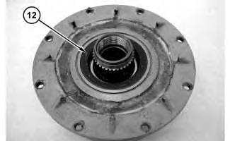
15. Position cover assembly (8) on the opposite side.
16. Install O-ring seal (10) on cover assembly (8) .
15
g01208914
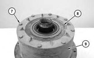
17. Position cover assembly (8) onto case (9) . Install bolts (7) and tighten bolts (7) to a minimum torque of 18 N·m (13 lb ft) up to a maximum torque of 31 N·m (23 lb ft).
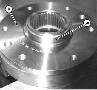
Illustration 16
g02092935
18. Apply Tooling (F) to the full diameter of the shoulder on drive flange (6) . Position new sleeve (6A) on drive flange (6) . The external chamfer on sleeve (6A) will be on top. Use Tooling (H) and a suitable press in order to install sleeve (6A) . Remove excess Tooling (F) .

Illustration 17
g01333295
19. Install drive flange (6) and O-ring seal (5) .
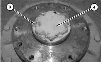
Illustration 18
g01333292
20. Install retainer (4) . Tighten retainer (4) to a minimum torque of 610 N·m (450 lb ft) up to a maximum torque of 750 N·m (550 lb ft). After achieving the torque range, overtighten retainer (4) as needed in order to align the next position for locking screws (3) .
21. Install locking screws (3) and tighten locking screws (3) to a minimum torque of 7 N·m (62 lb in) to a maximum torque of 10 N·m (89 lb in).
This is the sample of the manual
Click on the download link for complete Manual
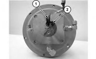
Illustration 19
22. Position sensor (1) . Install bolt (2) .
End By: Install the fan clutch. Refer to Disassembly and Assembly, "Fan Clutch - Install".
Copyright 1993 - 2024 Caterpillar Inc.
All Rights Reserved. Private Network For SIS Licensees.
Wed Mar 20 23:10:12 UTC+0530 2024