Product: EXCAVATOR
Model: 345B II EXCAVATOR CCC
Configuration: 345B Series II Excavator CCC00001-UP (MACHINE) POWERED BY 3176C Engine
Operation and Maintenance Manual
Flexxaire Fan Media Number -SEBU7290-04
Foreword
Literature Information
-01/02/2012
-06/02/2012
This manual should be stored in the operator's compartment in the literature holder or seat back literature storage area.
This manual contains safety information, operation instructions, transportation information, lubrication information and maintenance information.
Some photographs or illustrations in this publication show details or attachments that can be different from your machine. Guards and covers might have been removed for illustrative purposes.
Continuing improvement and advancement of product design might have caused changes to your machine which are not included in this publication. Read, study and keep this manual with the machine.
Whenever a question arises regarding your machine, or this publication, please consult your Cat dealer for the latest available information.
Safety
The safety section lists basic safety precautions. In addition, this section identifies the text and locations of warning signs and labels used on the machine.
Read and understand the basic precautions listed in the safety section before operating or performing lubrication, maintenance and repair on this machine.
Operation
The operation section is a reference for the new operator and a refresher for the experienced operator. This section includes a discussion of gauges, switches, machine controls, attachment controls, transportation and towing information.
s00037320
Photographs and illustrations guide the operator through correct procedures of checking, starting, operating and stopping the machine.
Operating techniques outlined in this publication are basic. Skill and techniques develop as the operator gains knowledge of the machine and its capabilities.
Maintenance
The maintenance section is a guide to equipment care. The Maintenance Interval Schedule (MIS) lists the items to be maintained at a specific service interval. Items without specific intervals are listed under the "When Required" service interval. The Maintenance Interval Schedule lists the page number for the step-by-step instructions required to accomplish the scheduled maintenance. Use the Maintenance Interval Schedule as an index or "one safe source" for all maintenance procedures.
Maintenance Intervals
Use the service hour meter to determine servicing intervals. Calendar intervals shown (daily, weekly, monthly, etc.) can be used instead of service hour meter intervals if they provide more convenient servicing schedules and approximate the indicated service hour meter reading. Recommended service should always be performed at the interval that occurs first.
Under extremely severe, dusty or wet operating conditions, more frequent lubrication than is specified in the maintenance intervals chart might be necessary.
Perform service on items at multiples of the original requirement. For example, at every 500 service hours or 3 months, also service those items listed under every 250 service hours or monthly and every 10 service hours or daily.
California Proposition 65 Warning
Diesel engine exhaust and some of its constituents are known to the State of California to cause cancer, birth defects, and other reproductive harm.
Battery posts, terminals and related accessories contain lead and lead compounds. Wash hands after handling.
Certified Engine Maintenance
Proper maintenance and repair is essential to keep the engine and machine systems operating correctly. As the heavy duty off-road diesel engine owner, you are responsible for the performance of the required maintenance listed in the Owner Manual, Operation and Maintenance Manual, and Service Manual.
It is prohibited for any person engaged in the business of repairing, servicing, selling, leasing, or trading engines or machines to remove, alter, or render inoperative any emission related device or element of design installed on or in an engine or machine that is in compliance with the regulations (40 CFR Part 89). Certain elements of the machine and engine such as the exhaust system, fuel system, electrical system, intake air system and cooling system may be emission related and should not be altered unless approved by Caterpillar.
Machine Capacity
Additional attachments or modifications may exceed machine design capacity which can adversely affect performance characteristics. Included would be stability and system certifications such as brakes, steering, and rollover protective structures (ROPS). Contact your Cat dealer for further information.
Cat Product Identification Number
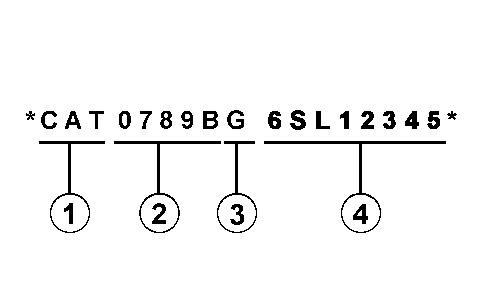
Effective First Quarter 2001 the Cat Product Identification Number (PIN) has changed from 8 to 17 characters. In an effort to provide uniform equipment identification, Caterpillar and other construction equipment manufacturers are moving to comply with the latest version of the product identification numbering standard. Non-road machine PINs are defined by ISO 10261. The new PIN format will apply to all Cat machines and generator sets. The PIN plates and frame marking will display the 17 character PIN. The new format will look like the following:
Illustration 1 g00751314
Where:
1. Caterpillar's World Manufacturing Code (characters 1-3)
2. Machine Descriptor (characters 4-8)
3. Check Character (character 9)
4. Machine Indicator Section (MIS) or Product Sequence Number (characters 10-17). These were previously referred to as the Serial Number.
Machines and generator sets produced before First Quarter 2001 will maintain their 8 character PIN format.
Components such as engines, transmissions, axles, etc. and work tools will continue to use an 8 character Serial Number (S/N).
Copyright 1993 - 2023 Caterpillar Inc. All Rights Reserved.
Private Network For SIS Licensees.
Thu Apr 13 16:06:51 UTC+0530 2023
This is the sample of the manual Click on the download link for complete Manual
Product: EXCAVATOR
Model: 345B II EXCAVATOR CCC
Configuration: 345B Series II Excavator CCC00001-UP (MACHINE) POWERED BY 3176C Engine
Operation and Maintenance Manual
Flexxaire Fan
Media Number -SEBU7290-04
Date -01/02/2012
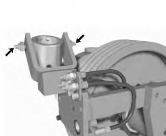
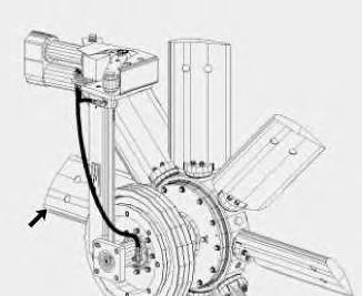
Actuator Support Bearing - Lubricate
SMCS - 1356-086
Illustration 1 g00563203
Updated -06/02/2012
i01061096
Apply lubricant to the grease fittings for the actuator support bearing. There is one grease fitting on each side of the collar.
Copyright 1993 - 2023 Caterpillar Inc. All Rights Reserved. Private Network For SIS Licensees. Thu Apr 13 16:12:13 UTC+0530 2023
Product: EXCAVATOR
Model: 345B II EXCAVATOR CCC
Configuration: 345B Series II Excavator CCC00001-UP (MACHINE) POWERED BY 3176C Engine
Operation and Maintenance Manual
Flexxaire Fan
Media Number -SEBU7290-04
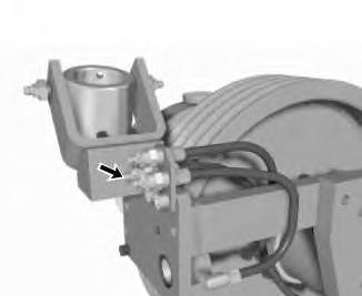
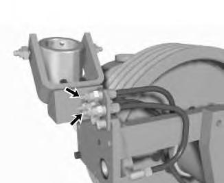
Bell Crank - Lubricate
SMCS - 1356-086
Date -01/02/2012
Updated -06/02/2012
i01075372
Illustration 1 g00563212
Apply lubricant to the grease fitting for the bellcrank. The fitting is closest to the actuator clevis in the cluster of fittings that are attached to the mounting bracket.
Copyright 1993 - 2023 Caterpillar Inc. All Rights Reserved. Private Network For SIS Licensees. Thu Apr 13 16:12:35 UTC+0530 2023
Product: EXCAVATOR
Model: 345B II EXCAVATOR CCC
Configuration: 345B Series II Excavator CCC00001-UP (MACHINE) POWERED BY 3176C Engine
Operation and Maintenance Manual
Flexxaire Fan
Media Number -SEBU7290-04
Blades - Inspect
SMCS - 1356-040
Illustration 1 g00563347
Updated -06/02/2012
i01075521
Check the fan blades for looseness and for unusual wear. Fan blades should be inspected more often when the fan is operated in highly abrasive environments.
If the blades are wearing out more quickly due to abrasive conditions, consult your Caterpillar dealer for abrasion resistant blades.
Copyright 1993 - 2023 Caterpillar Inc.
Rights Reserved.
Network For SIS Licensees. Thu Apr 13 16:12:52 UTC+0530 2023
Product: EXCAVATOR
Model: 345B II EXCAVATOR CCC
Configuration: 345B Series II Excavator CCC00001-UP (MACHINE) POWERED BY 3176C Engine
Operation and Maintenance Manual
Flexxaire Fan
Media Number -SEBU7290-04
Control Shaft Bushing - Lubricate
SMCS - 1356-086
Illustration 1 g00563389
Updated -06/02/2012
Apply lubricant to the grease fittings for the control shaft bushings. The two fittings are in the cluster of fittings that are attached to the mounting bracket.
The top fitting lubricates the control shaft bushing that is nearest to the belt pulleys. The fitting that is farthest from the actuator clevis lubricates the control shaft bushing that is nearest to the actuator.
Copyright 1993 - 2023 Caterpillar Inc. All Rights Reserved.
Private Network For SIS Licensees.
Thu Apr 13 16:13:25 UTC+0530 2023
i01075613
Product: EXCAVATOR
Model: 345B II EXCAVATOR CCC
Configuration: 345B Series II Excavator CCC00001-UP (MACHINE) POWERED BY 3176C Engine
Operation and Maintenance Manual
Flexxaire Fan Media
-01/02/2012
-06/02/2012
i01753953
Hub Oil - Add
SMCS - 1356
Note: Before you proceed, ensure that you know the correct model of the hydraulic actuated fan. Refer to Operation and Maintenance Manual, "Model View Illustrations" in order to identify the model of the fan.
Perform the following procedures in order to add oil to the fan hub.
Adding Oil to the Hubs of FX 2000 Hydraulic Actuated Fans
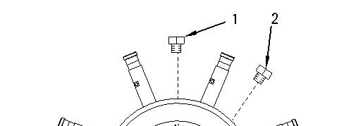
Illustration 1 g00898973
1. Rotate the hub until one of the oil drain plugs (1) or (2) is facing upward.
2. Remove oil drain plug (1) and oil drain plug (2) .
3. Insert a suitable dipstick into the hub. Use the dipstick to measure distance (A).
4. Add oil until dimension (A) is between 82.55 mm (3.25 inch) and 85.72 mm (3.375 inch). See Operation and Maintenance Manual, "Lubricant Viscosities and Refill Capacities" for the appropriate type of oil.
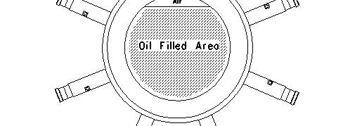
Note: Do NOT overfill the hub. An air space is required to allow the oil to expand. Failure to leave the desired air space will result in failure of the seals.
5. Allow the oil to settle in the hub. If you use synthetic oil, allow extra time for the oil to settle. Recheck the oil level. Add additional oil, if necessary.
Note: Do not overfill the hub. An air space is required. The air space will allow the oil to expand. Failure to leave an air space may result in seal failure.
6. Apply 6V-6640 Sealant to the threads of the oil drain plug. Reinstall the plug.
7. Check for any leaks and make any necessary repairs before operating the fan.
Adding Oil to the Hubs of FX 3000 Hydraulic Actuated Fans
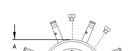
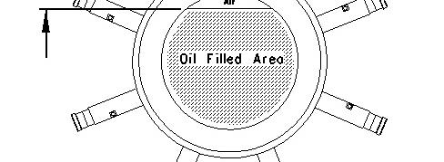
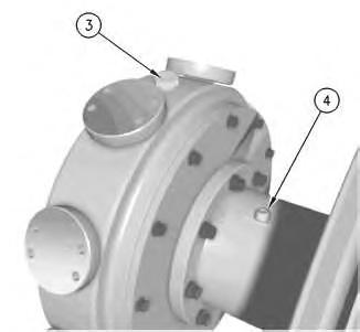
Illustration 3
Typical Hub of a Hydraulic Actuated Fan
1. Rotate the hub until oil filler plug (3) is facing upward.
2. Remove oil filler plug (3) and oil level plug (4) .
3. Add oil until oil begins to drip from the oil level hole. See Operation and Maintenance Manual, "Lubricant Viscosities and Refill Capacities" for the appropriate type of oil.
4. Allow the oil to settle in the hub. If you use synthetic oil, allow extra time for the oil to settle. Recheck the oil level. Add additional oil, if necessary.
Note: Do not overfill the hub. An air space is required. The air space will allow the oil to expand. Failure to leave an air space may result in seal failure.
5. Apply 6V-6640 Sealant to the threads of the oil level plug and the oil filler plug. Reinstall the plugs.
6. Check for any leaks and make any necessary repairs before operating the fan.
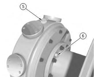
Adding Oil to the Hubs of FX 4000 and FX 5000 Hydraulic Actuated Fans
4 g00920249
Perform the following procedure in order to add oil to the fan hub.
1. Rotate the hub until oil filler plug (5) is facing upward.
2. Remove oil filler plug (5) and oil level plug (6) .
3. Add oil until oil begins to drip from the oil level hole. See Operation and Maintenance Manual, "Lubricant Viscosities and Refill Capacities" for the appropriate type of oil.
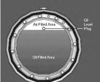
5 g00607921
4. Allow the oil to settle in the hub. If you use synthetic oil, allow extra time for the oil to settle. Recheck the oil level. Add additional oil, if necessary.
Illustration
Illustration
Note: Do not overfill the hub. An air space is required. The air space will allow the oil to expand. Failure to leave an air space may result in seal failure.
5. Apply 6V-6640 Sealant to the threads of the oil level plug and the oil filler plug. Reinstall the plugs.
6. Check for any leaks and make any necessary repairs before operating the fan.
Copyright 1993 - 2023 Caterpillar Inc. All Rights Reserved. Private Network For SIS Licensees. Thu Apr 13 16:13:53 UTC+0530 2023
Product: EXCAVATOR
Model: 345B II EXCAVATOR CCC
Configuration: 345B Series II Excavator CCC00001-UP (MACHINE) POWERED BY 3176C Engine
Operation and Maintenance Manual
Flexxaire Fan
Hub Oil - Change
SMCS - 1356-044
Hot oil and hot components can cause personal injury. Do not allow hot oil or hot components to contact the skin.
NOTICE
Care must be taken to ensure that fluids are contained during performance of inspection, maintenance, testing, adjusting and repair of the product. Be prepared to collect the fluid with suitable containers before opening any compartment or disassembling any component containing fluids.
Refer to Special Publication, NENG2500, "Caterpillar Tools and Shop Products Guide" for tools and supplies suitable to collect and contain fluids on Caterpillar products.
Dispose of all fluids according to local regulations and mandates.
Note: Before you proceed, ensure that you know the correct model of the hydraulic actuated fan. Refer to Operation and Maintenance Manual, "Model View Illustrations" in order to identify the model of the fan.
i01753950
Changing the Oil on the Hub of the FX 2000 Hydraulic Actuated Fan
Illustration 1 g00920273
1. Rotate the hub until oil drain plug (1) is facing upward.
2. Remove oil drain plugs (1) and (2) .
3. Slowly rotate the hub until oil starts to flow from oil drain plug (2). Capture the oil in a suitable container.
4. When the flow of oil stops, rotate the hub until the oil starts to flow again. Repeat this step until all of the oil has been removed from the hub.
5. See Operation and Maintenance Manual, "Hub Oil - Add" for the procedure to refill the hub with oil.
Changing the Oil on the Hub of the FX 3000 Hydraulic
Actuated Fan
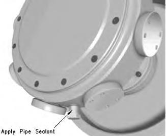
Illustration 2 g00563726
Typical location of the oil drain plug
1. Rotate the hub until the oil drain plug is facing downward.
Illustration 3
2. Remove oil filler plug (3) and oil level plug (4) .
3. Remove the oil drain plug and allow the oil to drain into a suitable container.
g00920279
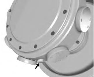
Illustration 4
Typical oil drain plug
4. Apply 6V-6640 Sealant to the threads of the oil drain plug and replace the plug.
5. Verify that oil filler plug (3) is facing upward.
6. Fill the hub with new oil. Refer to Operation and Maintenance Manual, "Lubricant Viscosities and Refill Capacities" for additional information.
7. Add oil until oil begins to drip from oil level hole (4) .
8. Apply 6V-6640 Sealant to the threads of oil level plug (4) and oil filler plug (3). Reinstall the plugs.
9. Check for any leaks and make any necessary repairs before operating the fan.
Changing the Oil on the Hub of the FX 4000 and FX 5000 Hydraulic Actuated Fan
Illustration 5
Typical location of the oil drain plug
g00563726
1. Rotate the hub until the oil drain plug is facing downward.
Illustration 6
g00920284
2. Remove oil filler plug (5) and oil level plug (6) .
3. Remove the oil drain plug and allow the oil to drain into a suitable container.
Illustration 7
Typical oil drain plug
4. Apply 6V-6640 Sealant to the threads of the oil drain plug and replace the plug.
5. Verify that oil filler plug (5) is facing upward.
6. Fill the hub with new oil. Refer to Operation and Maintenance Manual, "Lubricant Viscosities and Refill Capacities" for additional information.
7. Add oil until oil begins to drip from oil level hole (6) .
8. Apply 6V-6640 Sealant to the threads of the oil level plug and the oil filler plug. Reinstall the plugs.
9. Check for any leaks and make any necessary repairs before operating the fan.
Copyright 1993 - 2023 Caterpillar Inc. All Rights Reserved. Private Network For SIS Licensees. Thu Apr 13 16:14:17 UTC+0530 2023
Product: EXCAVATOR
Model: 345B II EXCAVATOR CCC
Configuration: 345B Series II Excavator CCC00001-UP (MACHINE) POWERED BY 3176C Engine
Operation and Maintenance Manual
Flexxaire Fan
Hub Oil Level - Check
SMCS - 1356-040
i01753894
Note: Before you proceed, ensure that you know the correct model of the hydraulic actuated fan. Refer to Operation and Maintenance Manual, "Model View Illustrations" in order to identify the model of the fan.
Perform the following procedure in order to check the oil level in the fan hub.
Checking the Oil Level on the Hub of the FX 2000 Hydraulic Actuated Fan
Illustration 1 g00920295
1. Rotate the hub until one of the oil drain plugs (1) is facing upward.
2. Remove oil drain plug (1) .
3. Insert an appropriate dipstick into the hub. Use the dipstick to measure distance (A). Distance (A) should be between 82.55 mm (3.25 inch) and 85.72 mm (3.375 inch). Add oil, if necessary. Refer to Operation and Maintenance Manual, "Hub Oil - Add" for the proper procedure to add oil.
4. Apply 6V-6640 Sealant to the threads of oil drain plug (1). Reinstall oil drain plug (1) .
5. Check for leaks. A low oil level may indicate that a leak is present. Check the oil level of the hub more often, if the oil level is consistently low.
Checking the Oil Level on the Hub of the FX 3000 Hydraulic Actuated Fan
Illustration 3
1. Rotate the hub until oil filler plug (3) is facing upward.
2. Remove oil level plug (4) .
3. Rotate the hub until oil begins to drip from the oil level hole. If the hub can be rotated more than 45° in either direction and no oil drips from the oil level hole, oil must be added. Refer to Operation and Maintenance Manual, "Hub Oil - Add" for the proper procedure.
4. Check for leaks. A low oil level may indicate that a leak is present. Check the oil level of the hub more often, if the oil level is consistently low.
Checking the Oil Level on the Hub of the FX 4000 and FX 5000 Hydraulic Actuated Fan
Illustration 4
Perform the following procedure in order to check the oil level in the fan hub.
1. Rotate the hub until oil filler plug (5) is facing upward.
2. Remove oil level plug (6) .
3. Rotate the hub until oil begins to drip from the oil level hole. If the hub can be rotated more than 45° in either direction and no oil drips from the oil level hole, oil must be added. Refer to Operation and Maintenance Manual, "Hub Oil - Add" for the proper procedure.
4. Check for leaks. A low oil level may indicate that a leak is present. Check the oil level of the hub more often, if the oil level is consistently low. Copyright 1993 - 2023 Caterpillar Inc.
Network For SIS Licensees. Thu Apr 13 16:14:43 UTC+0530 2023
This is the sample of the manual Click on the download link for complete Manual