Maintenance
The maintenance section is a guide to equipment care.
Copyright 1993 - 2024 Caterpillar Inc. All Rights Reserved. Private Network For SIS Licensees. Thu Jul 11 10:32:04 UTC+0530 2024
Product: EXCAVATOR
Model: 330F L EXCAVATOR MBX
Configuration: 330F L Excavator MBX00001-UP (MACHINE) POWERED BY C7.1 Engine
Operation and Maintenance Manual
Cat Grade Control for 2D and 3D Excavators
Media Number -M0077726-01 Publication Date -01/12/2017 Date Updated -19/12/2017
Safety Messages
SMCS - 7405
Do not operate or work on this machine unless you have read and understand the instructions and warnings in the Operation and Maintenance Manuals. Failure to follow the instructions or heed the warnings could result in injury or death. Contact your Cat dealer for replacement manuals. Proper care is your responsibility.
Failure to use an approved access system during installation and removal of components could result in slipping and falling which could result in personal injury or death. To prevent injury or death, use an approved access system to reach the appropriate mounting locations of the components. Do not climb on the machine. Maintain three-points of contact and/or use a safety harness.
Unexpected blade movement may occur when the blade control system is in automatic mode. Unexpected blade movements that occur while mounting or dismounting the machine may result in injury or death.
i06858456
Before dismounting the machine, always place the automatic blade control system into manual mode and follow the machine parking procedures specified in the machine Operation Manual.
Crushing Prevention and Cutting Prevention
Support the equipment properly when you work beneath the equipment. Do not depend on the hydraulic cylinders to hold up the equipment. An attachment can fall if a control is moved, or if a hydraulic line breaks.
Unless you are instructed otherwise, never attempt adjustments while the machine is moving. Also, never attempt adjustments while the engine is running.
Whenever there are attachment control linkages, the clearance in the linkage area will increase or the clearance in the linkage area will decrease with movement of the attachment. Stay clear of all rotating and moving parts.
Keep objects away from moving fan blades. The fan blade will throw objects or cut objects. Do not use a kinked wire cable or a frayed wire cable.
Wear gloves when you handle wire cable. When you strike a retainer pin with force, the retainer pin can fly out. The loose retainer pin can injure personnel. Make sure that the area is clear of people when you strike a retainer pin.
In order to avoid injury to your eyes, Wear protective glasses when you strike a retainer pin.
Chips or other debris can fly off objects when you strike the objects. Make sure that no one can be injured by flying debris before striking any object.
Operation
Clear all personnel from the machine and from the area.
Clear all obstacles from the path of the machine. Beware of hazards (wires, ditches, and so on).
Be sure that all windows are clean.
Secure the doors and the windows in the open position or in the shut position.
Adjust the rear mirrors (if equipped) for the best visibility close to the machine.
Make sure that the horn, the travel alarm (if equipped), and all other warning devices are working properly.
Fasten the seat belt securely.
Warm up the engine and the hydraulic oil before operating the machine.
Only operate the machine while you are in a seat. The seat belt must be fastened while you operate the machine. Only operate the controls while the engine is running.
While you operate the machine slowly in an open area, check for proper operation of all controls and all protective devices. Before you move the machine, make sure that no one will be endangered.
Do not allow riders on the machine unless the machine has the following equipment:
• Additional seat
• Additional seat belt
• Rollover Protective Structure (ROPS)
Note any needed repairs during machine operation. Report any needed repairs.
Avoid any conditions that can lead to tipping the machine. The machine can tip when you work on hills, on banks and on slopes. Also, the machine can tip when you cross ditches, ridges, or other unexpected obstructions.
Avoid operating the machine across the slope. When possible, operate the machine up the slopes and down the slopes.
Maintain control of the machine.
Do not overload the machine beyond the machine capacity.
Be sure that the hitches and the towing devices are adequate.
Never straddle a wire cable. Never allow other personnel to straddle a wire cable.
Before you maneuver the machine, make sure that no personnel are between the machine and the trailing equipment.
Always keep the Rollover Protective Structure (ROPS) installed during machine operation.
Monitor the location of components that are mounted to the blade. Ensure that the components do not come into contact with other parts of the machine during operation.
Copyright 1993 - 2024 Caterpillar Inc. All Rights Reserved. Private Network For SIS Licensees. Thu Jul 11 10:32:34 UTC+0530 2024
This is the sample of the manual Click on the download link for complete Manual
Product: EXCAVATOR
Model: 330F L EXCAVATOR MBX
Configuration: 330F L Excavator MBX00001-UP (MACHINE) POWERED BY C7.1 Engine
Operation and Maintenance Manual
Cat Grade Control for 2D and 3D Excavators
Media Number -M0077726-01
Publication Date -01/12/2017
Date Updated -19/12/2017
i07231229
Display Description
SMCS - 7490
Machine Display
Introduction
The Machine display is mounted on the right-hand side of the cab. The Machine display provides useful machine information to assist the operator in operation of the machine. The Machine Display also provides a user interface for both machine operation and for 2D Grade system usage. For 3D Grade system usage, refer to Section "TD520 Grade Display" .
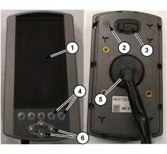
Working with the Display Illustration 1
(1) LCD display
(2) Beeper
(3) USB port
(4) Softkey buttons
(5) Main connector
(6) Arrow buttons Table 1
1 LCD display
2 Beeper
3 USB port
4 Softkey buttons
5 Main connector
6 Arrow buttons
The LCD display (1) shows the information from the machine and 2D Grade system needed by the operator.
The Beeper (2) allows the display to provide audible indication of certain functions by the system and the display.
The USB port (3) can be used to offload a limited amount of data from the display such as the work tool list.
The Softkey buttons (4) allow the operator to select the function indicated by the icon in the space directly above the button.
The Main connector port (5) connects the display to the machine and provides power to the display.
The Arrow buttons (6) allow the operator to navigate menus, scroll settings, and adjust numerical values.
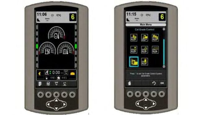
Navigation and Selection
The Machine Monitor provides the user interface for the operation and configuration of the system. To operate and configure the Grade system, navigating the Machine Monitor menus and screens as well as selecting and configuring settings is essential.
Operations can be activated or set using the softkeys (4) shown at the bottom of the LCD display (1) The softkey button operation is indicated by the icon directly above the button.
To navigate the system, the Arrow buttons (6) may be used to adjust values and settings or to move the highlighted selection through the menu structure. Once menu items or values are highlighted using the Arrow buttons (6), the highlighted item may be confirmed with the "OK" softkey button.
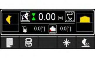
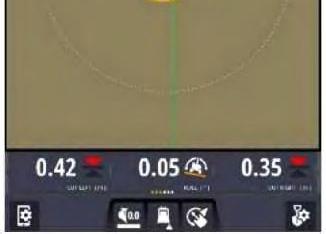
Grade Information on the Machine Display
The Grade information on the Machine Monitor is shown in the footer of the main screen.
3
g06181332
The Grade information on the Machine Monitor shows critical Grade information such as the Depth to Grade, Bucket Slope Angle, Bench Mode, Linkage Elevation Monitor System limits, and Bucket Focus. There are multiple patterns of softkey buttons that can be changed by using the Pattern Change softkey on this main screen. Refer to The Operation for Machine Monitor section for more details.
TD520 Grade Display
Introduction
The Grade Display is a computer that is used to interface with the Cat® Grade Control system. This section describes the operation of the display.
Working with the Display
Illustration
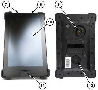
Illustration 4
(7) Suspend/resume (power) button
(8) Volume rocker
(9) Main connector port
(10) LCD display
(11) USB port
(12) Speaker
Table 2 Item Feature Function
7 Suspend/Resume (power) button
8 Volume rocker
9 Main connector port
10 LCD display
11 USB port
12 Speaker
Gestures
The Suspend/Resume (power) button (7) is used to power the display up and power it down.
The Volume Rocker (8) is used to turn the display volume up or down.
The Main Connector Port (9) connects the display to the machine sensors and provides power to the display.
The LCD display (10) shows the machine views and design plans.
The USB port (11) is primarily used for moving data files to and from the display.
The Speaker (12) is the display audio output device.
The display recognizes universal touch gestures to enable an operator to interact with the system.
Gestures Used to Interact with the Display
Tap: - briefly touch the display screen with fingertip.
Double tap: - tap the display screen two times in quick succession with fingertip.
Touch: - place fingertip on display screen surface as if pressing a physical button.
Double touch: - quickly tap display screen two times and briefly press on the second tap.
Touch and hold: - place finger on display screen and do not remove.
Drag: - touch a target on the display screen and move fingertip across the display screen without losing contact.
Touch, hold, and drag: - Touch a target and hold briefly to "grab" the target and then drag.
Swipe: - quickly brush fingertip on display screen surface.
Pinch: - touch two fingers to display screen a distance apart and bring the same two fingers closer together while still touching the screen.
Spread: - touch two fingers to display screen close together and move the same two fingers further apart while still touching the screen.
5
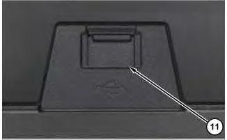
(11) USB port
g06151230
USB port (11) allows the user to perform the following tasks:
• Load design data from the USB to the system.
• Save design data from the system to the USB.
USB Port and Display Memory
Files and data are stored on the display in system memory. To access the files, the files need to be transferred from the display onto a USB flash drive. The files and data on the USB flash drive can then be directly accessed from a laptop, desktop computer, or SiteVision Office software.
Note: When a USB flash drive is inserted into the display, system operation is temporarily disabled. System operation resumes when the USB flash drive is removed.
6
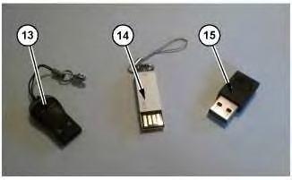
(13) Plastic covered connector
(14) Unprotected connector
(15) Metal covered connector
g06152068
Illustration
Illustration
Note: Only use a USB flash drive with a metal covered connector (15). When using a USB flash drive with plastic surrounding the connector (13), the display may fail to recognize the drive. When using a USB flash drive with no metal surround on the connector (14), the drive can be inserted upside down or contact can be broken interrupting the file transfer.
Note: The system only supports USB flash drives formatted as FAT32
Working With Display Information
When working with the display, a mix of menus, dialogs, and screens are used. The availability of some user interface features may be limited by the absence or presence of particular sensors on the machine.
Working with TD520 Grade Display Screens
TD520 Grade Display screens display a mix of text and graphics that provide information such as the slope or elevation of the cutting edge or the position of the machine. Depending on the configuration of the system, varying numbers of TD520 Grade Display screens can be viewed, such as:
• Plan view
• Terrain
• Cut/Fill
• Cross-section view
• Profile view
• Level (bubble) view
Work Screen Features
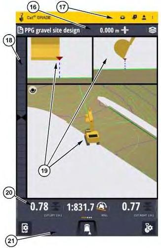
Illustration 7
(16) Guidance bar
(17) Action bar
(18) Light bar
(19) View stage
(20) Text item ribbon (21) Setting bar
Table 3
Contextual
Help Floating Icon
The Contextual Help Floating Icon is a movable button that appears on every screen. The Contextual Help Floating Icon can be relocated by touching and dragging the icon to a new location on the screen. Tapping the Contextual Help Floating Icon will activate a dialogue that describes the current screen or provides basic instructions for using the screen it is activated on.
Lightbar
Refer to Section "On-Screen Lightbars".
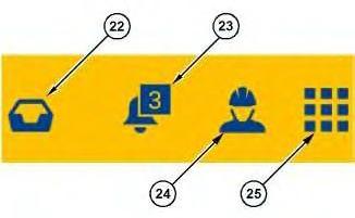
Action Bar
Illustration 8
(22) System messages (23) Messages (24) Operator Menu (25) Overflow menu
g06155234
The action bar is always visible. The information in the action bar is present on all screens except the Splash Screen and the Login Screen.
Table 4
Item Feature Description
22 System messages The inbox for messages, user prompts, and requests to the operator.
23 Alarms and alerts Messages that highlight Problems.
24 Operator menu Displays a banner with the username of the currently logged in operator and a Logout button.
25 Overflow menu Opens a menu for Help, About, zSnap, and other linked applications.
Guidance Bar
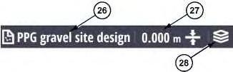
Illustration 9
(26) File name (when in design mode)
(27) Elevation offset (28) Design overlays
The Guidance bar contains design measurement definitions.
Table 5
Item Feature Description
26 File name (when in design mode) Displays the name of the design file
27 Elevation offset
28 Design overlays
View Stage
Refer to "Views" Section.
Text Item Ribbon
May display both mainfall slope and cross slope or only mainfall slope (Illustration 9 is displaying Elevation Offset only).
Opens the dialog to turn on/off the visualization of the machine, the focus point, points, mapping, linework, etc.
10
The Text Item Ribbon provides a row of live feed numerical gauge views. The number of gauges can exceed the visible width of the ribbon. In those cases the other gauge views can be seen by swiping left or right on the ribbon with one finger (refer to Section "Gestures" for swiping instruction).
Settings Bar
g06155236
Illustration
g06155237
Illustration 11
g06155238
The settings bar contains buttons an operator can press to open screens for changing settings, to activate features, or set benchmarks.
Views
Plan View
Illustration 12
Plan view
g06241705
Plan view shows the machine in a top-down view on the design. When the plan view is set to rotate, both the linework and the machine icon rotate to keep the machine pointing toward the top of the screen.
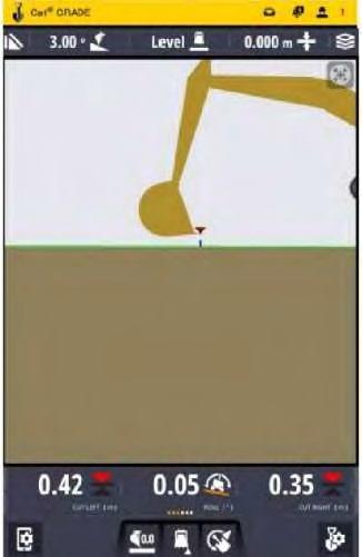
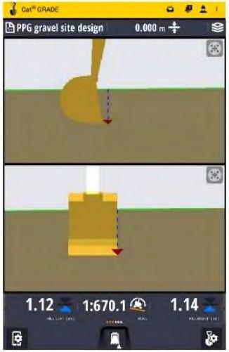
Cross-section View
13
Cross-section view, left orientation
g06241706
The cross-section view displays a cross-section representation of the design surface. Cross-section view shows the cutting edge relative to the guidance surface. The cross-section view is useful for monitoring the height of the cutting edge relative to the design surface, and the distance of the implement from the horizontal alignment.
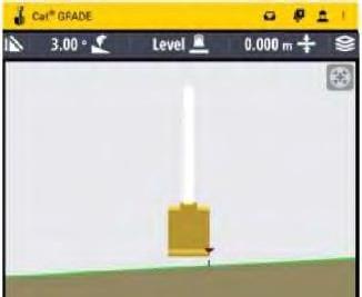
Profile View
Illustration
Illustration 14 g06241710
Profile view
Profile view shows the machine as a side-on-view to the design. Profile view provides a representation of the machine relative to the guidance surface. If a 3D guidance method is chosen and a design is loaded, then the profile view shows a long section of the design surface. As the body of the machine rotates, the design surface representation updates accordingly.
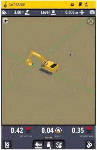
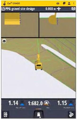
3D View
Illustration 15 g06241712
3D view shows the machine and the surroundings of the plan as a three dimensionally rendered object. 3D view provides a representation of the machine situated within the terrain the machine is working. 3D view delivers a tool to increase situational awareness relative to the excavation plan.
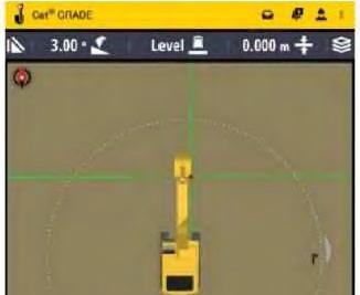
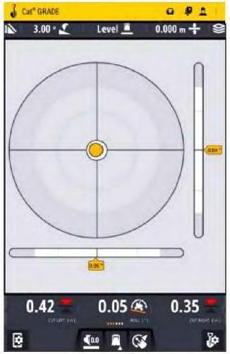
Level (bubble) View
3D view
Illustration 16
Level (bubble) view
g06241714
Level view displays the current pitch and roll of an excavator, and is useful for helping to level the machine. Level view displays a level bubble, horizontal and vertical level bars, and an angle measurement. The level bubble provides a visual representation of the current pitch and roll information coming from the pitch and roll sensors. The pitch and roll text items appear in Level view by default, and are the only text items available.
The outer ring represents 45 degrees, the inner ring represents 22.5 degrees, and where the horizontal and vertical lines intersect represents 0 degrees. The bubble, the horizontal and vertical level bars, and the text items all update as the machine moves and the pitch and roll readings change.
Layouts
The different layout formats are given below:
• one view
• two views
• three views
Illustration 17 g06241716
One view
One view is a single view perspective that takes up the entire viewing stage of the display.
Illustration 18 g06241721
Two views
Two views split the viewing stage equally in half horizontally which provides two separate views, each half of the total vertical viewing stage.
Illustration 19 g06241725
Three views
Three views split the viewing stage horizontally into an upper section that is one third of the total vertical viewing stage and a lower section that is two thirds. The upper section, the one that is one third of the vertical viewing stage is split equally in half. This provides two viewing panels in the top section and one in the lower section.
View Manipulation
Zooming the View
Any view panel can be zoomed in or zoomed out to enable an operator to see more of a view or greater detail in a view.
20 g06241727
When zoomed in more detail can be seen on the screen. Zoomed in, less of the design and linework are visible.
• Use the pinch gesture to zoom in. Refer to Illustration 20.
Illustration
Illustration 21
g06241728
When zoomed out less detail is visible on the screen. Zoom out, more of the design and linework are visible.
• Use Spread gesture to zoom out. Refer to Illustration 21.
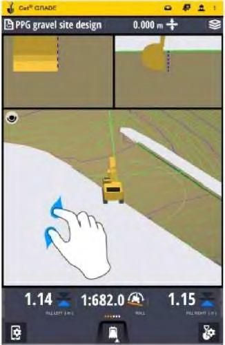
Panning Views
Any view panel image can be moved up, down, left, or right. This is "Panning".
To pan a view in any direction, the operator uses the drag gesture sliding the finger of the operator in any direction to pull the view panel image in that direction. Refer to Illustration 23. Refer to Section "Gestures" for more details.
Note: Illustration 23 is used to show view manipulation for the 3D View. However, the principle of that manipulation is the same for any view.
Centering a view
Any view can be panned and almost any view can be zoomed. If an operator has intentionally or accidentally panned and/or zoomed a view and needs to reset that view, the "Centering" button can be
used. The "Centering" button will recenter the view and set the view back to its default zoom (magnification). The "Centering" button will appear in the upper right corner of a viewing panel. The "Centering" button will only appear if the view in a viewing panel has been panned or zoomed. If a view has not been panned or zoomed, the Centering button will not be visible.
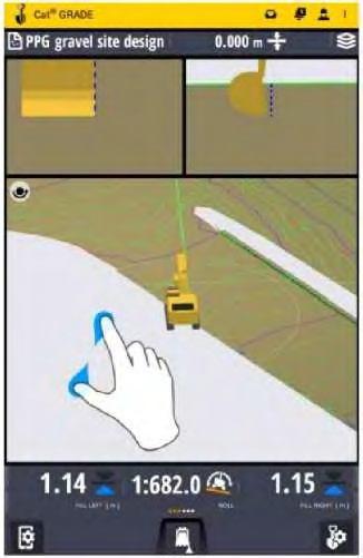
Panning and Rotating the 3D View
Rotate configuration
Pan configuration
The 3D view can rotate, pan, and zoom. By default the 3D View issetto be rotated. This is indicated by the"Rotate/Pan toggle" button in the upper left corner of the 3d View. To switch between rotate and pan, tap the "Rotate/Pan toggle" button. It will switch from the rotate configuration (Illustration 18) to the pan configuration (Illustration 19). Tapping the "Rotate/Pan toggle" button again will return it to the rotate configuration.
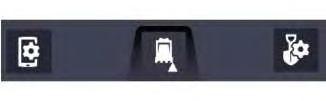
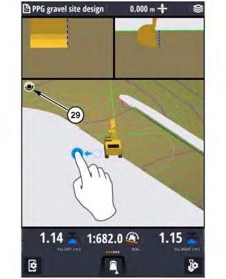
Illustration 22
g06241729 (29) "Rotate/Pan toggle" button in the Pan configuration
To rotate the 3D image, use the drag gesture. Refer to Section "Gestures" for more details.
This is the sample of the manual Click on the download link for complete Manual