
This is the sample of the manual
Click on the download link for complete Manual

Product: EXCAVATOR
Model: 330D2 L EXCAVATOR SZK
Configuration: 330D2 L Excavator SZK00001-UP (MACHINE) POWERED BY C7.1 Engine
Disassembly and Assembly C7.1 Engines
i05292093
Accessory Drive - Remove and Install - Accessory Drive SAE "A"
SMCS - 1207-010
Removal Procedure Table 1 Required Tools
Keep all partsclean from contaminants.
Contaminants may cause rapid wear and shortenedcomponent life. NOTICE
Care must be taken to ensure that fluids are containedduring performance of inspection, maintenance, testing, adjusting and repair of the product. Be prepared to collect the fluid with suitable containers
before opening any compartment or disassembling any component containing fluids.
Dispose of all fluids according to local regulations and mandates.
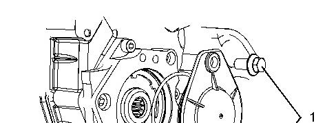

1
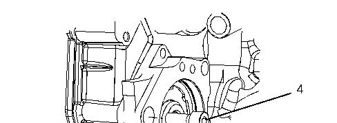
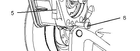

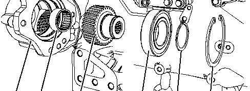
Illustration 2 g03360848
1. If necessary, remove Original Equipment Manufactures (OEM) driven equipment from auxiliary drive (5). Refer to the OEM for the correct procedure.
2. If the OEM driven equipment was not installed onto auxiliary drive (5). Remove cover plate (3) and remove O-ring seal (2).
3. Remove allen head screws (4) and allen head screw(6) from accessory drive housing (5).
4. Remove accessory drive housing (5) from the front housing.
5. Remove gasket (7) from accessory drive housing (5).
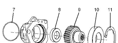
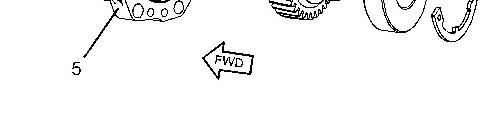
6. If necessary, followStep 6.a through Step 6.d in order to disassemble the accessory drive.
a. Remove circlip (11) from accessory drive housing (5).
b. Place accessory drive housing (5) onto a suitable support. Press the assembly of gear (9), bearing (10) and bearing (8) out of accessory drive housing (5).
c. Use Tooling (A) in order to remove bearing (10) from gear (9).
d. Use Tooling (A) in order to remove bearing (8) from gear (9).
Installation Procedure Table 2
Keep all parts
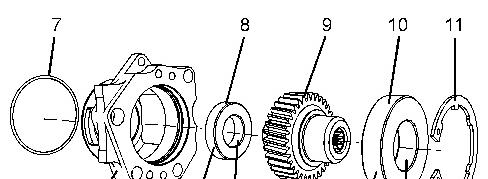
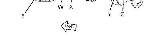
Illustration 4 g03431617
1. If necessary, followStep 1.a through Step 1.e in order to assemble the accessory drive.
a. Inspect the condition of the teeth and the splinesof gear (9) for wear and damage. Inspect bearing (10), bearing (8), and circlip (11). Inspect accessory drive housing (5) for wear and damage. Replace any componentsthat are worn or damaged.
b. Apply a small continuousbead of Tooling (B) to inner Surface (X) of bearing (8). Place the inner race of bearing (8) onto a suitable support. Press the shaft of gear (9) into bearing (8) until the shoulder of the gear isagainst the bearing. Remove any excess compound.
c. Apply a small continuousbead of Tooling (B) to inner Surface (Z) of bearing (10). Place the inner race of bearing (10) onto a suitable support. Press the shaft of gear (9) into bearing (10) until the shoulder of the gear isagainst the bearing. Remove any excess compound.
d. Apply a small continuousbead of Tooling (B) to the outer Surface (W) and the outer Surface (Y) of bearing (8) and bearing (10). Place accessory drive housing (5) on a suitable support. Press the assembly of gear (9) into the accessory drive housing. Ensure that bearing (10) and bearing (8) are against the front face of the recesses in accessory drive housing (5). Remove any excesscompound.
e. Install circlip (11) into the groove in accessory drive housing (5). Ensure that circlip (11) is correctly positioned in the groove.
2. Inspect the bore in the front housing for damage. If necessary, replace the front housing. Refer to Disassembly and Assembly, "Housing (Front) - Remove" and Disassembly and Assembly, "Housing (Front) - Install" for the correct procedure.
3. Position a new gasket (7) to accessory drive housing (5).
4. Lightly lubricate bearing (10), bearing (8), and gear (9) with clean engine lubricating oil. Install the assembly of the accessory drive to the front housing. Ensure that the flange on the accessory drive housing is flush with the front housing.

Illustration 5
g03360848
5. Install newM8 allen head screws (4) to accessory drive housing (5).
6. Install newM10 allen head screw (6) to accessory drive housing (5).
7. Tighten M8 allen head screws (4) to a torque of 22 N·m (195 lb in).
8. Tighten M10 allen head screw(6) to a torque of 44 N·m (32 lb ft).
9. Repeat Step 7 to ensure correct torque of M8 allen head screws (4).
10. Ensure that there is tactile backlash between the idler gear and the accessory drive gear.
Illustration 6 g03360847
11. If necessary, install the OEM driven equipment to auxiliary drive (5). Refer to the OEM for the correct procedure.
12. If the OEM driven equipment is not being installed to the auxiliary drive. Use Tooling (C) in order to lubricate a new O-ring seal (2). Install O-ring seal (3) (not shown) to cover plate (3) install the cover assembly to the auxiliary drive and install bolts (1).
13. Tighten bolts (1) to a torque of 16 N·m (142 lb in).
Product: EXCAVATOR
Model: 330D2 L EXCAVATOR SZK
Configuration: 330D2 L Excavator SZK00001-UP (MACHINE) POWERED BY C7.1 Engine
Disassembly and Assembly C7.1 Engines
i05292096
Accessory Drive - Remove and Install - Accessory Drive SAE
"B"
SMCS - 1207-010
Removal Procedure Table 1 Required Tools
Keep all partsclean from contaminants.
Contaminants may cause rapid wear and shortenedcomponent life. NOTICE
Care must be taken to ensure that fluids are containedduring performance of inspection, maintenance, testing, adjusting and repair of the product. Be prepared to collect the fluid with suitable containers
before opening any compartment or disassembling any component containing fluids.
Dispose of all fluids according to local regulations and mandates.
1. Remove the auxiliary equipment from the accessory drive housing. Refer to the Original Equipment Manufactures (OEM) for the correct procedure.
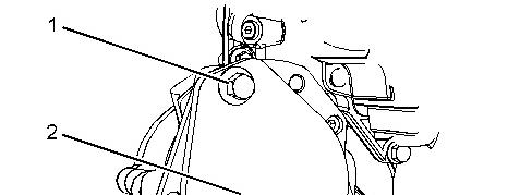
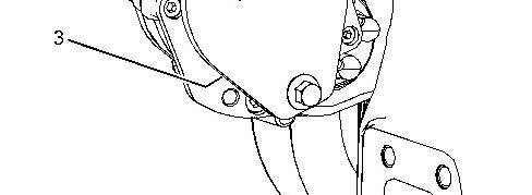

Illustration 1 g03360850
2. If the OEM driven equipment has not been installed to the auxiliary drive, remove bolts(1). Remove cover plate (2) and remove O-ring seal (3) (not shown).

2
3. Remove circlip (9) from housing (4).
4. Remove gear assembly (6) from housing (4).
5. If necessary, followStep 5.a through Step 5.c in order to disassemble gear assembly (6).
a. Remove circlip (8) from gear assembly (6).
b. Use Tooling (A) in order to remove bearing (7) from gear (6).
c. Use a suitable tool in order to remove bearing (5) from housing (4).
Installation Procedure
Keep all partsclean from contaminants.
Contaminants may cause rapid wear and shortenedcomponent life.
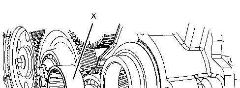
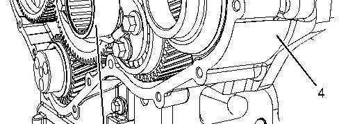

Illustration 3 g03431639
1. Apply a small continuousbead of Tooling (B) to outer Surface (X) of bearing (5).
2. Use a suitable tool in order to install bearing (5) to housing (4). Remove any excess bearing mount compound.


Illustration 4 g03431658
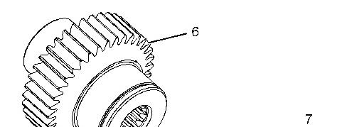
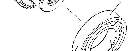

Illustration 5 g03431659
3. If necessary, followStep 3.a through Step 3.g in order to assemble bearing (7) onto gear (6).
a. Inspect the condition of the teeth and the splinesof gear (6) for wear and damage. Inspect bearing (7) circlip (8) and circlip (9).
b. Inspect the bore in housing (4) for damage. If necessary, replace the front housing. Refer to Disassembly and Assembly, "Housing (Front) - Remove" and Disassembly and Assembly, "Housing (Front) - Install" for the correct procedure.
c. Apply a small continuousbead of Tooling (B) to inner Surface (Y) of bearing (7). Place the inner race of bearing (7) onto a suitable support. Press the shaft of gear (6) into bearing (7) until the shoulder of the gear isagainst the bearing. Remove any excess bearing mount compound.
d. Install circlip (8) into the groove in gear (6).
e. Apply a small continuousbead of Tooling (B) to the outer Surface (Z) of bearing (7)
f. Install gear assembly (6) to housing (4). Ensure that the shaft of gear (6) is correctly aligned with the bearing in housing (4). Remove any excess bearing mount compound.
g. Install circlip (9) into the groove in accessory drive housing (4). Ensure that circlip (9) is correctly positioned in the groove.
4. Ensure that there is tactile backlash between the idler gear and the accessory drive gear.

Illustration 6 g03360850
5. Install the auxiliary equipment to the accessory drive housing. Refer to the OEM for the correct procedure.
6. If the OEM driven equipment is not being installed to the auxiliary drive. Install a newOring seal (3) (not shown) and cover plate (2). Install bolts (1) and tighten the boltsto a torque of 44 N·m (33 lb ft).
Copyright 1993 - 2021 Caterpillar Inc. All Rights Reserved. Private Network For SIS Licensees. Fri Feb 26 15:14:20 UTC+0530 2021
Product: EXCAVATOR
Model: 330D2 L EXCAVATOR SZK
Configuration: 330D2 L Excavator SZK00001-UP (MACHINE) POWERED BY C7.1 Engine
Disassembly and Assembly
C7.1 Engines
i07111287
Air Compressor - Remove and Install - Single Cylinder Air Compressor
SMCS - 1803-010
Removal Procedure
Table 1 RequiredTools
(1) The Crankshaft Turning Tool is usedon the front pulley. (2) This Tool is usedin theaperture for the electricstarting motor.
Note: Either Tooling (A) can be used. Use the Tooling that is most suitable.
NOTICE
Care must be taken to ensure that fluids are containedduring performance of inspection, maintenance, testing, adjusting and repair of the product. Be prepared to collect the fluid with suitable containers
before opening any compartment or disassembling any component containing fluids.
Dispose of all fluids according to local regulations and mandates.
NOTICE
Keep all partsclean from contaminants.
Contaminants may cause rapid wear and shortenedcomponent life.
Note: Put identification marks on all hoses, on all hose assembliesand on all tube assembliesfor installation purposes. Plug all hose assembliesand tube assemblies. Plugging all hose assemblies and tube assemblieshelps to prevent fluid lossand also helpsto keep contaminants from entering the system.
Do not disconnect the air lines until the air pressure in the system is at zero. If hose is disconnected under pressure itcancause personal injury.
1. Release the pressure from the air system. Refer to the Original Equipment Manufactures (OEM) for the correct procedure.
2. Drain the coolant from the cooling system into a suitable container for storage or for disposal. Refer to Operation and Maintenance Manual, "Cooling System Coolant - Change" for the correct draining procedure.
3. If the engine is equipped with a hydraulic pump on the rear of the air compressor, remove the hydraulic pump. Refer to the OEM for the correct procedure.
4. Use Tooling (A) to rotate the crankshaft so that number one piston is at the top center position on the compression stroke. Refer to Systems Operation, Testing and Adjusting, "Finding Top Center Position for No.1 Piston" for the correct procedure.
Note: The air compressor must be timed with the engine to minimize engine vibration.
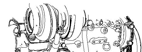
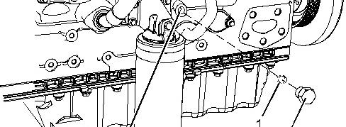

Illustration 1 g01966313
Typicalexample
5. Remove plug (2) from the cylinder block. Remove O-ring seal (1) from the plug.
6. Install Tooling (B) into Hole (X) in the cylinder block. Use Tooling (B) to lock the crankshaft in the correct position.
Note: Do not use excessive force to install Tooling (B). Do not use Tooling (B) to hold the crankshaft during repairs.

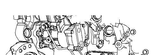
2 g03360856
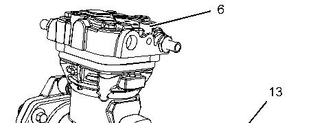
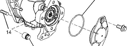

Illustration 3 g01965121
Typicalexample
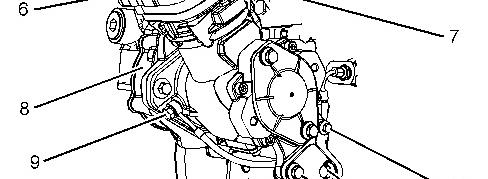
7. Slide hose clamps along coolant hose (3) and coolant hose (4). Disconnect coolant hose (3) and coolant hose (4) from air compressor (6).
8. Disconnect the air linesfrom port (5) (not shown) and air linesfrom port (7). Refer to the OEM for the correct procedure.
9. Remove banjo bolt (9) and sealing washers from air compressor (6).
10. Remove bolt (10) and bolt (12) from support bracket (11) and remove the support bracket.
11. Support air compressor (6) and remove nuts (15). Remove the air compressor from front housing (8).
12. If necessary, remove studs (14) from front housing (8).
13. If necessary, remove bolts(17) and remove plate (16). Remove O-ring seal (13) from plate (16).
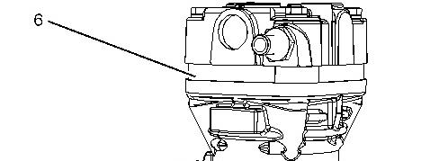
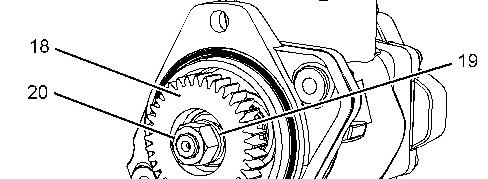

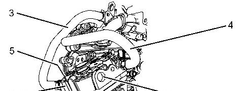
Illustration 4 g01964860
Typicalexample
14. Remove O-ring seal (21) from air compressor (6).
15. If necessary, followStep 15.a through Step 15.b to remove gear (18) from the crankshaft of the air compressor.
a. Use a suitable tool to prevent the shaft of the compressor from rotating. Remove nut (20) and remove spring washer (19).
b. Use Tooling (C) to remove gear (18) from the crankshaft of the air compressor.
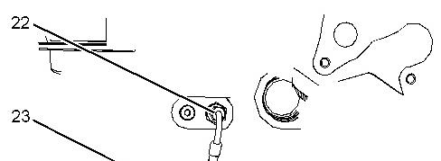
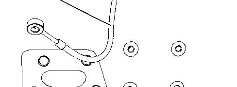
Illustration 5 g03360857
16. If necessary, followStep 16.a through Step 16.b to remove the hose assembly.
a. Make a temporary mark to identify the position of hose assembly (23).
b. Disconnect nut (22) and remove hose assembly (23).
Installation Procedure
Table 2 Required Tools
(1) The Crankshaft Turning Tool is usedon the front pulley.
(2) This Tool is usedin theaperture for the electricstarting motor.
Note: Either Tooling (A) can be used. Use the Tooling that is most suitable.
NOTICE
Keep all partsclean from contaminants.
Contaminants may cause rapid wear and shortenedcomponent life.
NOTICE
Care must be taken to ensure that fluids are containedduring performance of inspection, maintenance, testing, adjusting and repair of the product. Be prepared to collect the fluid with suitable containers before opening any compartment or disassembling any component containing fluids.
Dispose of all fluids according to local regulations and mandates.
6 g03360857
This is the sample of the manual
Click on the download link for complete Manual