

Product: MINI HYD EXCAVATOR
Model: 308D MINI HYD EXCAVATOR GBT
Configuration: 308D Mini Hydraulic Excavator GBT00001-UP (MACHINE) POWERED BY 4M40 Engine
Disassembly and Assembly 4M40 DIESEL ENGINE SHOP MANUAL
Media Number -KENR5078-00
General
SMCS - 7555-012
Information Location
Publication Date -01/11/2007
Date Updated -01/12/2014
KENR50780012
This shop manual is published for the information and guidance of personnel responsible for maintenance of Mitsubishi 4M40 series diesel engine, and includes procedures for adjustment and maintenance services. We earnestly look forward to seeing that this manual is made full use of in order to perform correct services with no wastage.
Disassembly and Assembly information is located under General Service Information.
Copyright 1993 - 2020 Caterpillar Inc. All Rights Reserved. Private Network For SIS Licensees.
Thu Dec 17 12:50:45 UTC+0530 2020
Product: MINI HYD EXCAVATOR
Model: 308D MINI HYD EXCAVATOR GBT
Configuration: 308D Mini Hydraulic Excavator GBT00001-UP (MACHINE) POWERED BY 4M40 Engine
Disassembly and Assembly
308D CR Excavator Engine Supplement
i02947850
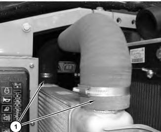
Aftercooler - Remove and Install
SMCS - 1063-010
Removal Procedure
Start By:
A. Remove the engine hood. Refer to Disassembly and Assembly, "Hood - Remove and Install".
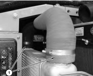
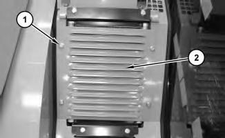
1. Disconnect two hoses (1) .

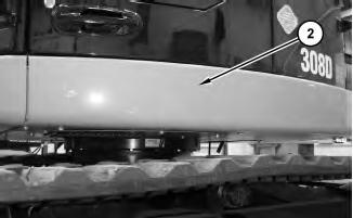
Illustration 2
2. Remove panel (2) .
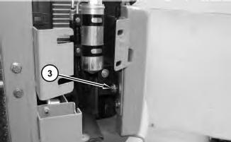
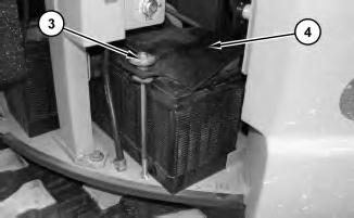
Illustration 3
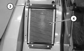
3. Remove bolt (3) .

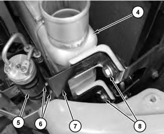
4
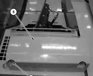
4. Remove bolts (6) and place refrigerant receiver-dryer (5) to the side. Remove bolts (8) and bracket assembly (7). Remove the bolts from the rear of aftercooler (4). Remove aftercooler (4) .
Installation Procedure
5 g01461889
1. Position aftercooler (4). Install bracket assembly (7) and bolts (8). Install the bolts for the rear of aftercooler (4). Position refrigerant receiver-dryer (5) and install bolts (6) .
6
2. Install bolt (3) .
7
Install panel (2) .
This is the sample of the manual
Click on the download link for complete Manual
4. Connect two hoses (1) .
End By: Install the engine hood. Refer to Disassembly and Assembly, "Hood - Remove and Install".
1993 - 2020 Caterpillar Inc.
Rights Reserved.
Network For SIS Licensees. Thu Dec 17 12:39:05 UTC+0530 2020
Product: MINI HYD EXCAVATOR
Model: 308D MINI HYD EXCAVATOR GBT
Configuration: 308D Mini Hydraulic Excavator GBT00001-UP (MACHINE) POWERED BY 4M40 Engine
Disassembly and Assembly
308D CR Excavator Engine Supplement
i02942935
Air Cleaner - Remove and Install
SMCS - 1051-010; 1054-010
Removal Procedure
1. Open the engine hood.
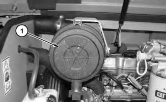
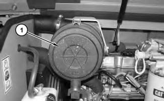
Illustration 1 g01458643
2. Remove cover (1) .
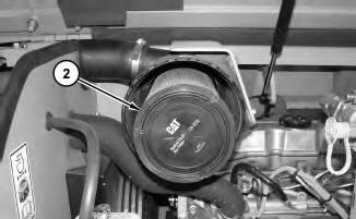
2
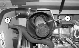
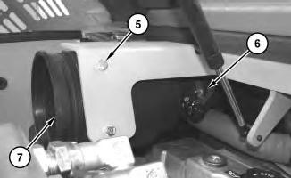
Illustration 4
g01458649
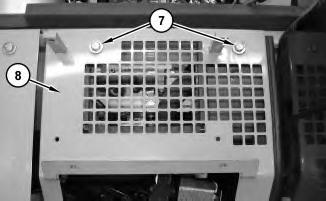
5. Disconnect hose (6). Remove bolts (5) and air cleaner housing (7) .
Installation Procedure
Illustration 5
g01458649
1. Position air cleaner housing (7) and install bolts (5). Connect hose (6) .
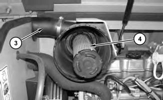
Illustration 6
g01458647
2. Install hose (3). Install secondary filter (4) .
Install primary filter (2) .
8
4. Install cover (1) .
5. Close the engine hood.
Copyright 1993 - 2020 Caterpillar Inc. All Rights Reserved. Private Network For SIS Licensees. Thu Dec 17 12:38:50 UTC+0530 2020
Product: MINI HYD EXCAVATOR
Model: 308D MINI HYD EXCAVATOR GBT
Configuration: 308D Mini Hydraulic Excavator GBT00001-UP (MACHINE) POWERED BY 4M40 Engine
Disassembly and Assembly
308D CR Excavator Engine Supplement
i02952459
Alternator - Install
SMCS - 1405-012
Installation Procedure
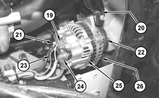
Illustration 1
g01467127
1. Install alternator (25). Install bolts (20) and (26) .
2. Install belts (22) on alternator (25). Refer to Operation and Maintenance Manual, "BeltsInspect/Adjust/Replace".
3. Connect harness assemblies (19), (21), (23), and (24) .
2
3
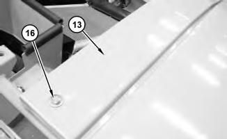
Illustration 4
g01467568
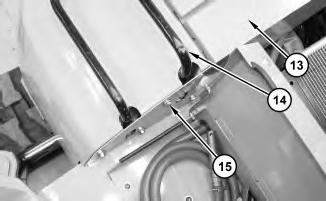
Illustration 5
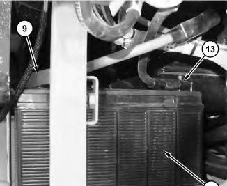
6. Install panel (13) and bolt (16) .
g01467578
7. Install four bolts (15) in panel (13). Install bolt (14) in panel (13) .
6
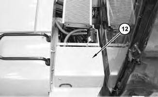
8. Close door (12) .
7
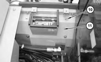
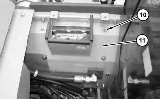
9. Install six bolts (10) in panel (11) .
8
9
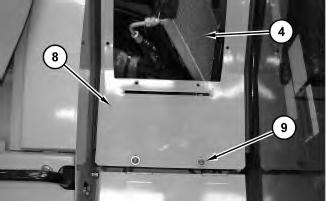
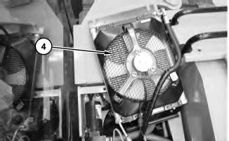
10. Position refrigerant condenser (4), as shown.
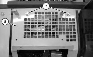
11. Install cover (8). Install bolts (9) and (7) .
10
12. Install cover (5) and bolts (6) .
13. Position refrigerant condenser (4), as shown.
14. Install bolts (3) .
15. Install panel (2) and bolts (1) .
16. Turn the battery disconnect switch to the ON position.
End By: Install the engine hood. Refer to Disassembly and Assembly, "Hood - Remove and Install".
Product: MINI HYD EXCAVATOR
Model: 308D MINI HYD EXCAVATOR GBT
Configuration: 308D Mini Hydraulic Excavator GBT00001-UP (MACHINE) POWERED BY 4M40 Engine
Disassembly and Assembly
308D CR Excavator Engine Supplement
i02950608
Alternator - Remove
SMCS - 1405-011
Removal Procedure
Start By:
A. Remove the engine hood. Refer to Disassembly and Assembly, "Hood - Remove and Install".
1. Turn the battery disconnect switch to the OFF position.
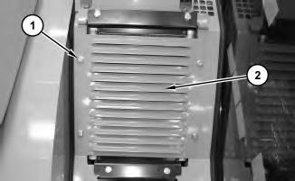
Illustration 1
2. Remove bolts (1) and panel (2) .
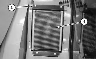
Illustration 2
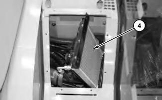
Illustration 3
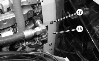
3. Remove bolts (3). Position refrigerant condenser (4), as shown.
Illustration 4
.
5
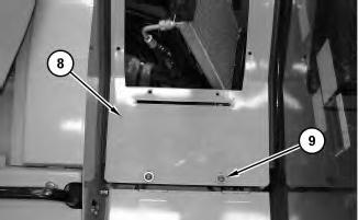
5. Remove bolts (7) and (9). Remove cover (8) .
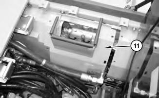
6. Remove six bolts (10) from panel (11) .

Illustration 8
7. Open door (12) .
Illustration 9
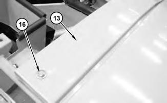
Illustration 10
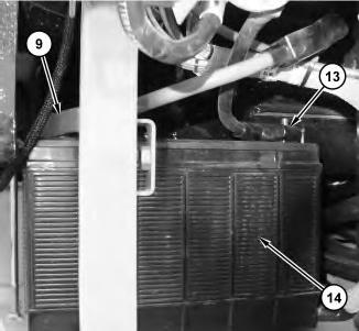
8. Remove bolt (14) from panel (13). Remove four bolts (15) from panel (13) .
9. Remove bolt (16) and panel (13) .
11
10. Place refrigerant condenser (4) aside, as shown.
12
11. Remove panel (11) .

Illustration 13
12. Remove bolts (17) and panel (18) .
Illustration 14 g01467127
13. Remove belts (22) from alternator (25). Refer to Operation and Maintenance Manual, "BeltsInspect/Adjust/Replace".
14. Disconnect harness assemblies (19), (21), (23), and (24) .
15. Remove bolts (20) and (26). Remove alternator (25) . Copyright 1993 - 2020 Caterpillar Inc. All Rights Reserved. Private Network For SIS Licensees.
Product: MINI HYD EXCAVATOR
Model: 308D MINI HYD EXCAVATOR GBT
Configuration: 308D Mini Hydraulic Excavator GBT00001-UP (MACHINE) POWERED BY 4M40 Engine
Disassembly and Assembly
308D CR Excavator Engine Supplement
i02947578
Battery - Remove and Install
SMCS - 1401-010
Removal Procedure
1. Turn the battery disconnect switch to the OFF position.
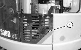
Illustration 1 g01460234
2. Remove panel (1) on the left side of the machine.
2
3. Remove guard (2) .
3
4. Remove nut (3), the washer, and the spacer. Repeat for the other two hold-downs. Remove cover (4) .
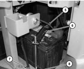
Illustration 4
g01461140
5. Remove bolt (5). Remove hold-down clamp (6). Remove the other hold-down clamp.
6. Disconnect cable assembly (7). Remove stud (8) .
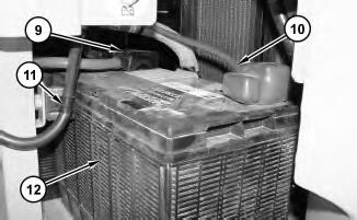
Illustration 5
7. Disconnect negative battery cable (9) .
g01461143
8. Disconnect positive battery cable (10). Remove clamp (11). Remove battery (12) .
This is the sample of the manual
Click on the download link for complete Manual
6
Installation Procedure
1. Position battery (14). Connect battery cable (13). Connect battery cable (9) .