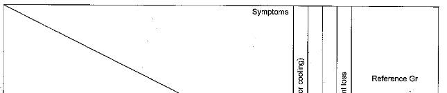
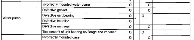
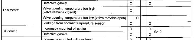
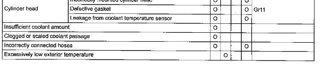
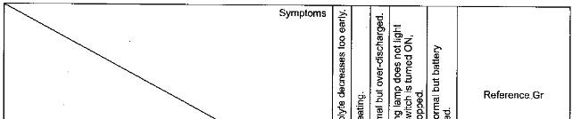
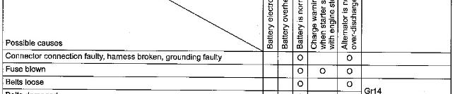
Troubleshooting
General Inspection And Adjustment
Inspection And Adjustment Of Belt
Tension
https://127.0.0.1/sisweb/sisweb/techdoc/techdoc_print_page.jsp?returnurl=/sisweb/sisweb/
This is the sample of the manual
Click on the download link for complete Manual
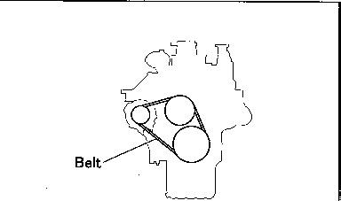
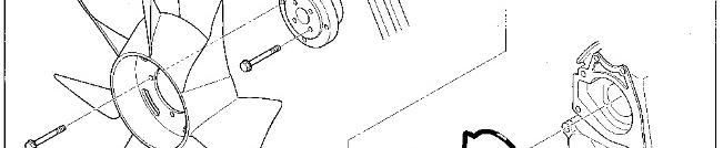
* Make sure that there is no oil or grease on the belts. Belts soiled with oil or grease may easily slip, resulting in deteriorated performance of the cooling system.
* The water pump pulley is driven by two belts. Always replace the two belts simultaneously to ensure that both belts have the same tension.
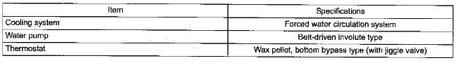
Service Standards (Unit: mm)
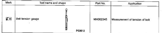
Special Tools
Inspection and Cleaning Procedure
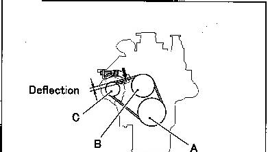
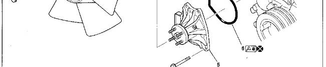
Inspection: Tension of belts
https://127.0.0.1/sisweb/sisweb/techdoc/techdoc_print_page.jsp?returnurl=/sisweb/sisweb/
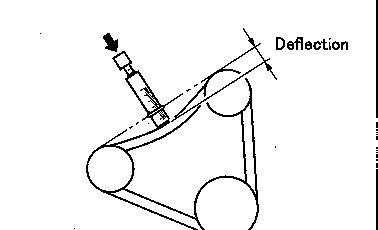
* Press each belt at a central portion between pulleys with a force of approximately 98 N {10 kgf} as shown in the illustration and measure the amount of deflection of the belt.
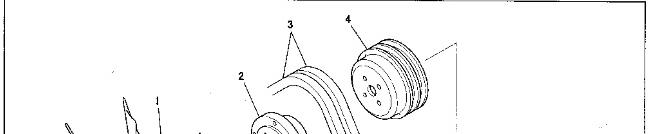
A: Crankshaft pulley
B: Water pump pulley
C: Alternator pulley
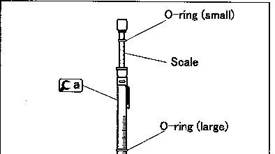
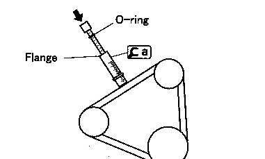
* Place the small O-ring on
at the scale mark corresponding to 98N {10 kgf} (press force).
* Place the large O-ring on
at the scale mark corresponding to the maximum permissible deflection value specified for the belt.
* Place at a central portion between pulleys of the belt and push the handle (indicated by the arrow in the illustration) until the O-ring touches the flange.
https://127.0.0.1/sisweb/sisweb/techdoc/techdoc_print_page.jsp?returnurl=/sisweb/sisweb/
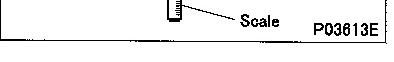
*Measure the amount of deflection of the belt.
* If the measured value deviates from the standard value range, adjust the tension of the belt as follows.
Adjustment of belts
https://127.0.0.1/sisweb/sisweb/techdoc/techdoc_print_page.jsp?returnurl=/sisweb/sisweb/
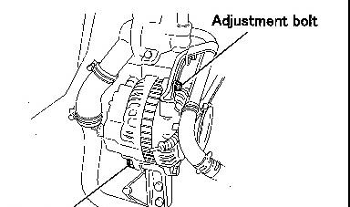
* Loosen the alternator mounting bolt, and adjust the tension of the belt by moving the alternator as required.
* After the adjustment is completed, retighten the mounting bolt firmly.
* Excessive tension in the belt may damage not only the belt itself but also the bearings of the related components.
https://127.0.0.1/sisweb/sisweb/techdoc/techdoc_print_page.jsp?returnurl=/sisweb/sisweb/
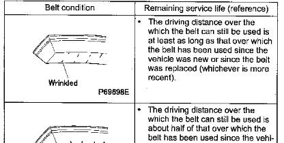
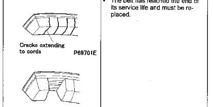
Inspection of Belts
* Visually check the belts for possible cracks and damage. Belt replacement time varies depending on the severity of cracks and damage that may be found through the check. Study the table given below for the applicable replacement time.
Coolant Replacement and Cleaning of Cooling System
Tightening Torque (Unit: N·m {kgf·m})
https://127.0.0.1/sisweb/sisweb/techdoc/techdoc_print_page.jsp?returnurl=/sisweb/sisweb/
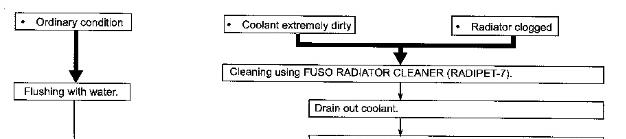
* Using the radiator for extended periods of time without cleaning can increase chance of rust and scale formation, which may cause engine overheating. The cooling system must be cleaned periodically.
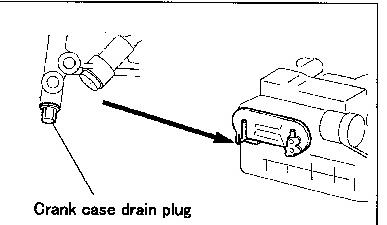
Draining of Coolant
* Opening the pressure cap while the coolant temperature is still high can cause hot coolant to spray out. Cover the pressure cap with a cloth, and loosen it slowly to let the pressure out before opening it fully.
* Drain the coolant only after it has cooled sufficiently to avoid getting scalded.
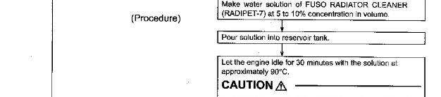
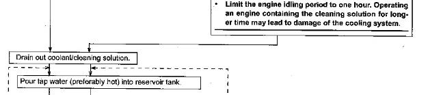
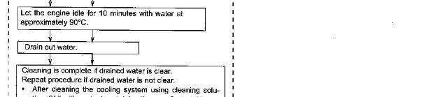
Cleaning Procedure
* Keep the coolant temperature at approximately 90°C so that the thermostat valve remains open and the coolant continues to circulate in the radiator.
* For the sake of convenience you can raise the coolant temperature quickly by covering the front of the radiator with corrugated cardboard or something similar.
https://127.0.0.1/sisweb/sisweb/techdoc/techdoc_print_page.jsp?returnurl=/sisweb/sisweb/
* Set the temperature adjusting lever of the heat controller at maximum so that the coolant can circulate freely in the heater piping area.
* In cases where a great amount of rust has accumulated it often happens that as a result of cleaning the radiator starts leaking. Conduct a thorough check for leakage after cleaning.
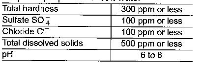
* Soft water to be used should have the following properties.
* Do not use hard water as it causes scale and rust.
* Select an appropriate cleaning method according to the condition of the cooling system as shown below.
https://127.0.0.1/sisweb/sisweb/techdoc/techdoc_print_page.jsp?returnurl=/sisweb/sisweb/
https://127.0.0.1/sisweb/sisweb/techdoc/techdoc_print_page.jsp?returnurl=/sisweb/sisweb/
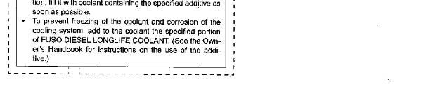
* FUSO DIESEL LONGLIFE COOLANT is flammable. Keep them away from heat and flames.
* If you accidentally splash FUSO DIESEL LONGLIFE COOLANT, FUSO ANTIFREEZE, OR RADIATOR ANTIRUST (RADIPET 9) in your eyes, wash it out immediately with water and seek medical attention.
Air Bleeding of Cooling System
* With the pressure cap removed and the coolant temperature at 90°C, let the engine idle in order to bleed air completely out of the cooling system.
* After air bleeding is completed, refill the reservoir tank with coolant as needed.
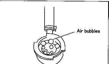
Air/Gas Leakage Test
* Presence of air or exhaust gas in coolant accelerates corrosion of the cooling system components. To prevent this, carry out air/gas leakage tests in accordance with the following procedure.
* Remove the pressure cap.
https://127.0.0.1/sisweb/sisweb/techdoc/techdoc_print_page.jsp?returnurl=/sisweb/sisweb/
* If the engine is hot, boiling coolant may spurt out from the filler port when the pressure cap is loosened. To avoid being scold, make sure to remove the pressure cap only when the coolant is cold.
* Run the engine until the coolant temperature rises to approximately 90°C.
* If air bubbles appear continuously through the filler port, there is air or exhaust gas penetrating into the cooling system.
* Presence of air in coolant can be an indication of loose cylinder head bolts, loose water pump mounting bolts, loose hose connections, and/or a damaged hose.
* Presence of exhaust gas in coolant can be an indication of a damaged cylinder head gasket and/or cracks in the cylinder head.
Inspection of Coolant Leak
* With the engine idling, check the coolant passage (radiator hose, water hose, etc.) for coolant leak.
* If any leak is found, check the installation condition of each part and retighten the loose part to the specified torque.
If any crack or damage is found on a pipe or hose, replace it to a new one.
https://127.0.0.1/sisweb/sisweb/techdoc/techdoc_print_page.jsp?returnurl=/sisweb/sisweb/
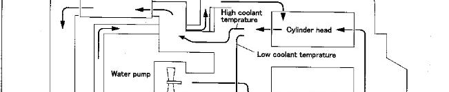
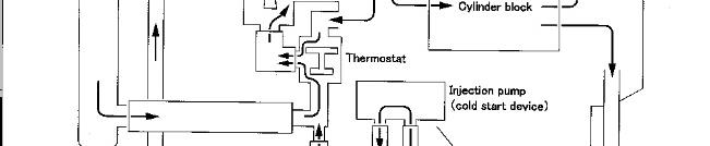
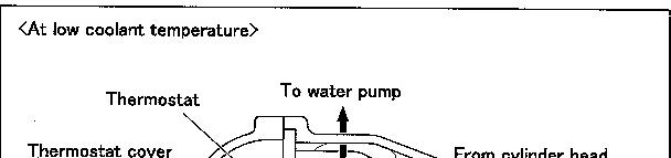
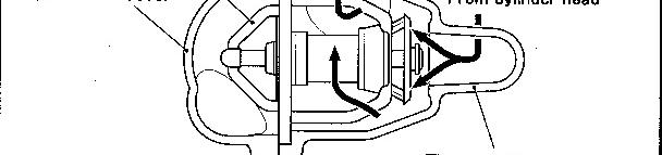
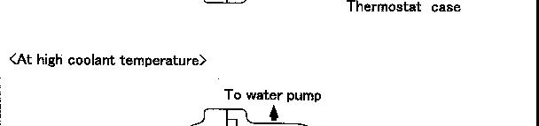
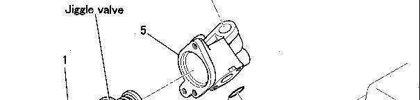
Thermostat
Disassembly Sequence
1 Thermostat cover
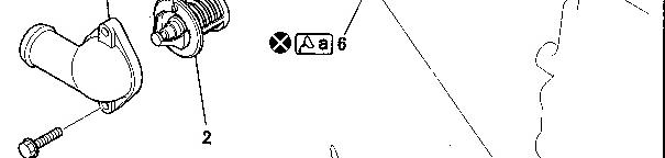
2 Thermostat
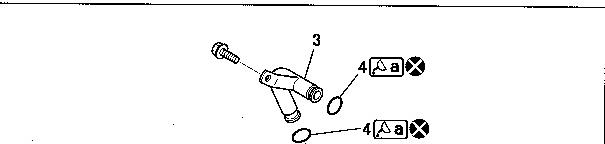
3 Bypass Pipe
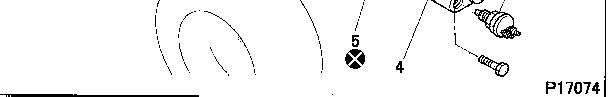
4 O-ring
5 Thermostat case
6: O-ring
X: Non-reusable parts
Assembly Sequence
Follow the disassembly sequence in reverse.
https://127.0.0.1/sisweb/sisweb/techdoc/techdoc_print_page.jsp?returnurl=/sisweb/sisweb/
* Keep the O-ring free of engine oil. Engine oil will make the Oring swell, which may cause leakage.
* Install the thermostat with the jiggle valve on the top.
Service standards (Unit: mm)
Lubricant and/or sealant
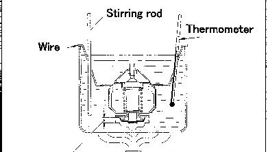
Inspection Procedure
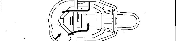
Inspection: Thermostat
* Stir the water using a stirring rod to maintain an even water temperature in the container, then conduct the tests indicated below.
* If the measured values deviate from the standard value ranges, replace the thermostat.
https://127.0.0.1/sisweb/sisweb/techdoc/techdoc_print_page.jsp?returnurl=/sisweb/sisweb/
(1) Valve opening temperature
* Hold the thermostat with wire to keep it away from the heat source.
* Heat the water gradually to the valve opening temperature.
* Maintain this temperature for five minutes and make sure that the valve is completely open.
* Make sure that the valve closes completely when the water temperature drops below 65°C.
(2) Valve lift
* Heat the water to a temperature slightly higher than the valve operating temperature. Maintain this temperature for five minutes and measure the valve lift.
1993 - 2018 Caterpillar Inc.
https://127.0.0.1/sisweb/sisweb/techdoc/techdoc_print_page.jsp?returnurl=/sisweb/sisweb/
Previous Screen
Product: NO EQUIPMENT SELECTED
Model: NO EQUIPMENT SELECTED
Configuration: NO EQUIPMENT SELECTED
General Service Information
4M40 DIESEL ENGINE SHOP MANUAL
MediaNumber-KENR5078-00
PublicationDate-01/11/2007
DateUpdated-01/12/2014
Electrical
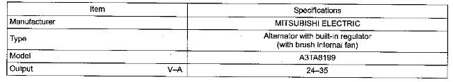
Specifications
Alternator
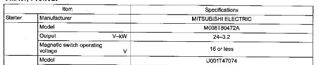
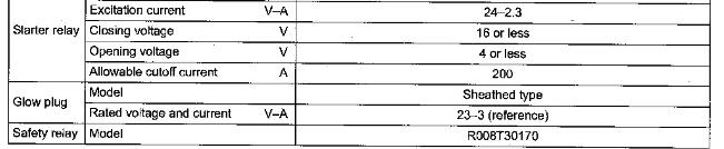
Starter, Preheat
https://127.0.0.1/sisweb/sisweb/techdoc/techdoc_print_page.jsp?returnurl=/sisweb/sisweb/
KENR50780008
Structure And Operation
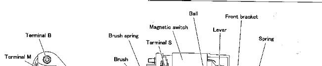
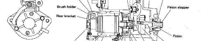
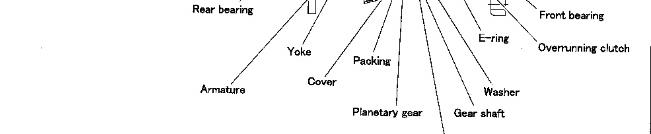
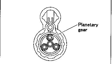
Starter
* This starter uses planetary gears as its reduction gearing mechanism.
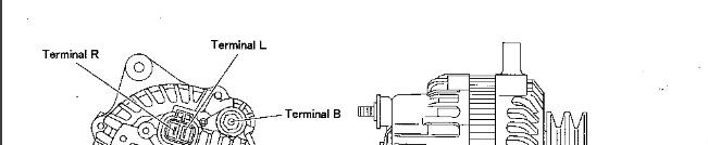
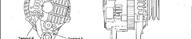
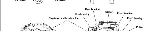
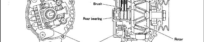
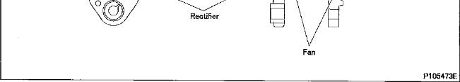
Alternator
<24V-35A>
https://127.0.0.1/sisweb/sisweb/techdoc/techdoc_print_page.jsp?returnurl=/sisweb/sisweb/
https://127.0.0.1/sisweb/sisweb/techdoc/techdoc_print_page.jsp?returnurl=/sisweb/sisweb/
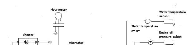
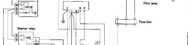
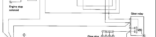
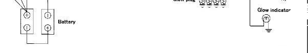
Circuit Diagram
Troubleshooting
https://127.0.0.1/sisweb/sisweb/techdoc/techdoc_print_page.jsp?returnurl=/sisweb/sisweb/
This is the sample of the manual
Click on the download link for complete Manual
https://127.0.0.1/sisweb/sisweb/techdoc/techdoc_print_page.jsp?returnurl=/sisweb/sisweb/