

PreviousScreen
Product: MINI HYD EXCAVATOR
Model: 307C MINI HYD EXCAVATOR BCM
Configuration: 307C & 307C SB Excavators BCM00001-UP (MACHINE) POWERED BY 4M40 Engine
Disassembly and Assembly
307C Excavator Machine Systems
Media Number -RENR4029-02
Publication Date -01/03/2005 Date Updated -29/03/2005
Accumulator (Hydraulic Pilot) - Remove and Install
SMCS - 5077-011-PS; 5077-012-PS
Removal Procedure
NOTICE
Care must be taken to ensure that fluids are contained during performance of inspection, maintenance, testing, adjusting and repair of the product. Be prepared to collect the fluid with suitable containers before opening any compartment or disassembling any component containing fluids.
Refer to Special Publication, NENG2500, "Caterpillar Tools andShop ProductsGuide" for tools and suppliessuitable to collect and contain fluidson Caterpillar products.
Dispose of all fluids according to local regulations and mandates.
Personal injury can result from hydraulic oil pressure and hot oil.
Hydraulic oil pressure can remain in the hydraulic system after the engine has been stopped. Serious injury can be caused if this pressure is not released before any service is done on the hydraulic system.
Make sure all of the attachments have been lowered, oil is cool before removing any components or lines. Remove the oil filler cap only when
the engine is stopped, and the filler cap is cool enough to touchwith your bare hand.
1. Release the hydraulic system pressure. Refer to Disassembly and Assembly, "Hydraulic System Pressure - Release".
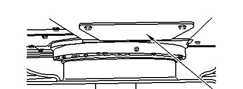
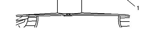
Illustration 1 g00889074
Bottomguard (1) is locatedon therearside of the swing gear.
2. Remove bottom guard (1) in order to gain access to the accumulator.
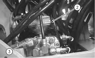
Illustration 2 g00888344
The above graphic is taken from the underside of the machine.
3. Loosen nut (3) and remove accumulator (2) .
Installation Procedure
Table 1
Required Tools
Tool Part Number
A 7S-5437 Nitrogen Charging Group 1
Note: Check the O-ring seal. If the O-ring seal is damaged or worn, use a new part for replacement.
NOTICE
Care must be taken to ensure that fluids are contained during performance of inspection, maintenance, testing, adjusting and repair of the product. Be prepared to collect the fluid with suitable containers before opening any compartment or disassembling any component containing fluids.
Refer to Special Publication, NENG2500, "Caterpillar Tools andShop ProductsGuide" for tools and suppliessuitable to collect and contain fluidson Caterpillar products.
Dispose of all fluids according to local regulations and mandates.
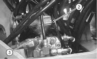
Illustration 3
g00888344
The above graphic is taken from the underside of the machine.
1. Position accumulator (2) for installation and tighten nut (3) .
2. Use Tooling (A) to charge the hydraulic accumulator.
Note: Refer to Tool Operating Manual, NEHS0598, " 9U-6740 Accumulator Charging Group Tool Operating Manual" for information on charging the accumulator.
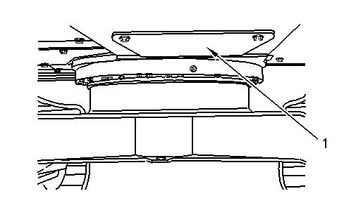
Illustration 4 g00889074
Bottomguard (1) is locatedon therearside of the swing gear.
3. Install bottom guard (1) .
4. Check the oil level in the hydraulic oil tank. Add hydraulic oil, if necessary. Refer to Operation and Maintenance Manual, SEBU7421, "Hydraulic System Oil Level - Check" for the correct procedure.
Copyright 1993 - 2020 Caterpillar Inc. All Rights Reserved. Private Network For SIS Licensees. Fri Mar 13 10:28:14 UTC+0530 2020
PreviousScreen
Product: MINI HYD EXCAVATOR
Model: 307C MINI HYD EXCAVATOR BCM
Configuration: 307C & 307C SB Excavators BCM00001-UP (MACHINE) POWERED BY 4M40 Engine
Disassembly and Assembly
307C Excavator Machine Systems
Media Number -RENR4029-02
Publication Date -01/03/2005 Date Updated -29/03/2005 i01734142
Actuator Motor (Damper Assembly) - Remove and Install
SMCS - 7304-010-MQ; 7309-010-MQ; 7320-010-MQ
Removal Procedure
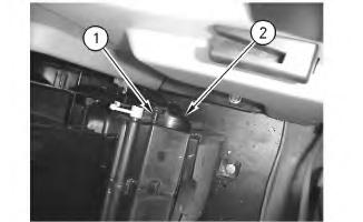
1 g00889190
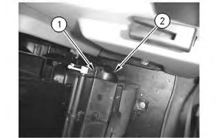
1. Slide the seat forward.
2. Remove screw(1) in order to remove cover (2) .
2
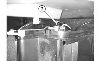
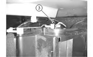
3. Disconnect harnessassembly (3) .
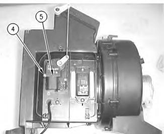
Illustration 3
Note: The unit wasremoved from the machine for photo purposes.
4. Remove screw(4) .
5. Remove actuator motor (5) .
Installation Procedure
This is the sample of the manual
Click on the download link for complete Manual
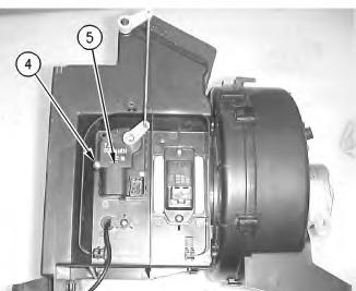
Illustration 4
Note: The unit wasremoved from the machine for photo purposes.
1. Install actuator motor (5) .
2. Install screw(4) .
5
3. Connect harness assembly (3) .
Install cover (2) . 5. Install screw(1) .
PreviousScreen
Product: MINI HYD EXCAVATOR
Model: 307C MINI HYD EXCAVATOR BCM
Configuration: 307C & 307C SB Excavators BCM00001-UP (MACHINE) POWERED BY 4M40 Engine
Disassembly and Assembly
307C Excavator Machine Systems
Media Number -RENR4029-02
Auxiliary Hydraulic Pump - Assemble - Blade
SMCS - 5073-AX
Assembly Procedure Table 1
Failure to properly assemble parts or failure to follow established procedures can lead to damage of the parts and assembly.
To avoid damage to parts, always identify andmarkthe parts so that they can be installed in the same location. Ensure that gear surfaces align. Never force parts during assembly.
1. Thoroughly clean all parts of the auxiliary pump prior to assembly. Put clean hydraulic oil on the parts during assembly. Check the condition of all parts of the pump assembly. If any of the parts are worn or damaged, use new partsfor replacement.
1
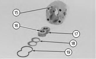
2. Ensure that dowels (15) are installed in the center case.
3. Use Tooling (A) to install bushings (16) in thrust plate (17). Install each bushing even with the outside of the thrust plate. Install thrust plate (17), plate (18) and square ring (19) in the correct positions in the center case.
2
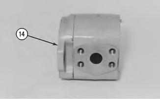
4. Install end frame (14) on the center case.
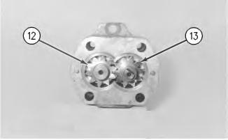
Illustration 3
g00535974
5. Install idler gear (12) and drive gear (13) in the center case.

Illustration 4
g00535976
6. Use Tooling (A) to install the bushings in thrust plate (11). Install each bushing even with the outside of the thrust plate. Install thrust plate (11) in the center case.
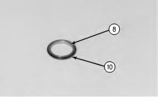
Illustration 5
7. Install O-ring seals (10) on guides (8).
g00535997
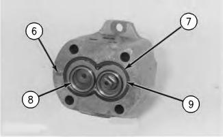
Illustration 6
g00535999
8. Install plate (9) and square ring (7) in the center case. Install guides (8).
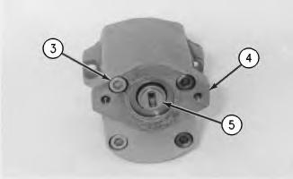
Illustration 7
g00536002
9. Position end plate (4) on the center case. Install bolts(3). Tighten the bolts to a torque of 62 ± 7 N·m (45 ± 5 lb ft).
10. Install coupling (5) on the drive gear of the pump.
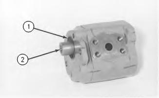
11. Install O-ring seal (1) in the end frame.
12. Install coupling (2) on the drive gear.
End By: Install the auxiliary hydraulic pump. Refer to Disassembly and Assembly, "Auxiliary Hydraulic Pump - Install".
1993 - 2020 Caterpillar Inc.
PreviousScreen
Product: MINI HYD EXCAVATOR
Model: 307C MINI HYD EXCAVATOR BCM
Configuration: 307C & 307C SB Excavators
BCM00001-UP (MACHINE) POWERED BY 4M40 Engine
Disassembly and Assembly
307C Excavator Machine Systems
Media Number -RENR4029-02
Publication Date -01/03/2005 Date Updated -29/03/2005
Auxiliary Hydraulic Pump - Disassemble - Blade
SMCS - 5073-AX
Disassembly Procedure
Start By:
i01787934
A. Remove auxiliary hydraulic pump assembly. Refer to Disassembly and Assembly, "Auxiliary Hydraulic Pump - Remove".
NOTICE
Failure to properly assemble parts or failure to follow established procedures can lead to damage of the parts and assembly.
To avoid damage to parts, always identify andmarkthe parts so that they can be installed in the same location. Ensure that gear surfaces align. Never force parts during assembly.
1. Thoroughly clean the outside of the auxiliary hydraulic pump.
Illustration 1
2. Remove coupling (2) from the drive gear. Remove O-ring seal (1) from the end frame.
Illustration 2
g00536002
3. Remove coupling (5) from the drive gear of the pump.
4. Remove bolts (3) and separate end plate (4) from the center case.

Illustration 3
g00535999
5. Remove guides (8) from the center case.
Note: Note the position of plate (9) in the center case. The plate must be reinstalled in the plate's original position.
6. Remove square ring (7) and plate (9) from the center case.
7. If necessary, remove dowels (6) from the center case.

Illustration 4
g00535997
8. Remove O-ring seal (10) from each guide (8).
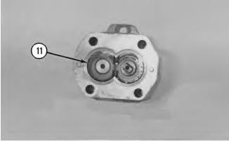
Illustration 5
g00535976
9. Remove thrust plate (11) from the center case. Remove the bushingsfrom thrust plate (11).
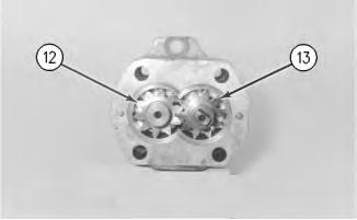
Illustration 6
10. Remove idler gear (12) and drive gear (13).
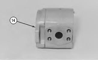
Illustration 7
g00535972
11. Remove end frame (14) from the center case.

Illustration 8
g00535971
Note: Note the position of plate (18) and thrust plate (17) from the center case. The plate and the thrust plate must be installed in the original positions in the center case.
12. Remove square ring (19), plate (18) and thrust plate (17) from the center case. Remove bushings (16) from thrust plate (17).
13. If necessary, remove dowels (15) from the center case.
PreviousScreen
Product: MINI HYD EXCAVATOR
Model: 307C MINI HYD EXCAVATOR BCM
Configuration: 307C & 307C SB Excavators BCM00001-UP (MACHINE) POWERED BY 4M40 Engine
Disassembly and Assembly
307C Excavator Machine Systems
Media Number -RENR4029-02
Publication Date -01/03/2005 Date Updated -29/03/2005
Auxiliary Hydraulic Pump - Install - Blade
SMCS - 5073-AX
Installation Procedure
NOTICE
Care must be taken to ensure that fluids are contained during performance of inspection, maintenance, testing, adjusting and repair of the product. Be prepared to collect the fluid with suitable containers before opening any compartment or disassembling any component containing fluids.
Refer to Special Publication, NENG2500, "Caterpillar Tools andShop ProductsGuide" for tools and suppliessuitable to collect and contain fluidson Caterpillar products.
Dispose of all fluids according to local regulations and mandates.
Note: Check the O-ring seals for wear or for damage. Replace the components, if necessary.
i01787939

Illustration 1
1. Install O-ring seal (9) and bushing (10) in the frame of the pump assembly.
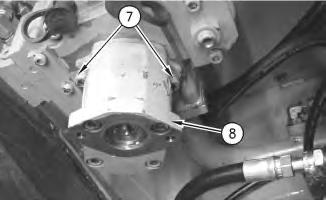
Illustration 2
g00884321
2. Position auxiliary hydraulic pump (8) and install bolts (7). Tighten the boltsto a torque of 62 ±7 N·m (45 ± 5 lb ft).
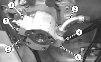
Illustration 3
3. Position block (6) and install bolts(4). Tighten the bolts to a torque of 80 ± 7 N·m (60 ± 5 lb ft).
4. Position block (1) and install bolts(3). Tighten the bolts to a torque of 80 ± 7 N·m (60 ± 5 lb ft).
5. Connect hose assemblies(5) and (2).
End By: Install the gear pump (pilot). Refer to Disassembly and Assembly, "Gear Pump (Pilot) - Install".
PreviousScreen
Product: MINI HYD EXCAVATOR
Model: 307C MINI HYD EXCAVATOR BCM
Configuration: 307C & 307C SB Excavators
BCM00001-UP (MACHINE) POWERED BY 4M40 Engine
Disassembly and Assembly
307C Excavator Machine Systems
Media Number -RENR4029-02
Publication Date -01/03/2005 Date Updated -29/03/2005 i01787925
Auxiliary Hydraulic Pump - Remove - Blade
SMCS - 5073-AX
Removal Procedure
Start By:
A. Remove the gear pump (pilot). Refer to Disassembly and Assembly, "Gear Pump (Pilot) - Remove and Install".
NOTICE
Care must be taken to ensure that fluids are contained during performance of inspection, maintenance, testing, adjusting and repair of the product. Be prepared to collect the fluid with suitable containers before opening any compartment or disassembling any component containing fluids.
Refer to Special Publication, NENG2500, "Caterpillar Tools andShop ProductsGuide" for tools and suppliessuitable to collect and contain fluidson Caterpillar products.
Dispose of all fluids according to local regulations and mandates.
Note: Put identification marks on all hose assemblies for installation purposes. Plug all hose assemblies. This helps to prevent fluid loss, and thishelps to keep contaminants from entering the system.
1
1. Disconnect hose assemblies (2) and (5).
2. Remove bolts (3) and block (1) .
3. Remove bolts (4) and block (6).
2
4. Remove bolts (7) and remove auxiliary hydraulic pump (8) from the main hydraulic pump.
5. Remove O-ring seal (9) and bushing (10) from the auxiliary hydraulic pump.
Copyright 1993 - 2020 Caterpillar Inc. All Rights Reserved. Private Network For SIS Licensees. Fri Mar 13 10:30:57 UTC+0530 2020
PreviousScreen
Product: MINI HYD EXCAVATOR
Model: 307C MINI HYD EXCAVATOR BCM
Configuration: 307C & 307C SB Excavators
BCM00001-UP (MACHINE) POWERED BY 4M40 Engine
Disassembly and Assembly
307C Excavator Machine Systems
Media Number -RENR4029-02
Publication Date -01/03/2005 Date Updated -29/03/2005
Blade - Remove and Install
SMCS - 6060-010
Removal Procedure
Start By:
A. Remove the blade cylinder. Refer to Disassembly and Assembly, "Blade Cylinder - Remove".
1. Put wood blocksunder the arms of the blade in order to support the blade.
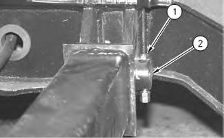
Illustration 1 g00555026
2. Remove the nuts and retaining bolt (1), and remove pin assembly (2). Repeat this procedure for the remaining blade arm.
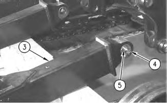
2
3. Start the machine and carefully move the machine away from blade arms(3). The weight of the blade assembly is approximately 172 kg (380 lb).
4. Remove four lip seals(4), and remove sleeve bearings(5) from the blade arms.
Installation Procedure
1. Thoroughly clean all mating surfaces before assembly.
2. Lower the temperature of the sleeve bearings. Position the sleeve bearings in the pin bore of the blade arms. Use Tooling (A) to install sleeve bearings(5) until the sleeve bearings are centered in the bores.
Illustration 3
3. Use Tooling (A) to install four lip seals(4) in the arms of the blade. Install the sealswith the lip toward the outside of the blade. Install the seals until the seals make contact with the sleeve bearings.
4
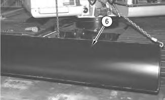
4. Attach a suitable lifting device to blade (6). Position the blade on the undercarriage frame.

Illustration 5
This is the sample of the manual
Click on the download link for complete Manual
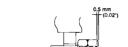

Illustration 6 g00356648
5. Install two pin assemblies (2) that secure the blade assembly to the frame. Install retaining bolts (1) and the nuts. Tighten the outside nut until the nut is 0.5 mm (0.02 inch) above the end of the retaining bolt. Tighten the inside nut to a torque of 70 ± 15 N·m (50 ±10 lb ft).
6. Lubricate mounting pins(2) with 5P-0960 Molybdenum Grease .
End By: Install the blade cylinder. Refer to Disassembly and Assembly, "Blade Cylinder - Install". Copyright 1993 - 2020 Caterpillar Inc. All Rights Reserved. Private Network For SIS Licensees. Fri Mar 13 10:04:05 UTC+0530 2020