

Product: MINI HYD EXCAVATOR
Model: 307B MINI HYD EXCAVATOR 7DZ
Configuration: 307B TRACK-TYPE EXCAVATOR /SWING BOOM ARRANGEME/ 7DZ00001-UP (MACHINE) POWERED BY 4M40 ENGINE
Disassembly and Assembly 4M40 DIESEL ENGINE SHOP MANUAL
Media Number -KENR5078-00
General
SMCS - 7555-012
Information Location
Publication Date -01/11/2007
Date Updated -01/12/2014
KENR50780012
This shop manual is published for the information and guidance of personnel responsible for maintenance of Mitsubishi 4M40 series diesel engine, and includes procedures for adjustment and maintenance services. We earnestly look forward to seeing that this manual is made full use of in order to perform correct services with no wastage.
Disassembly and Assembly information is located under General Service Information.
Copyright 1993 - 2020 Caterpillar Inc. All Rights Reserved. Private Network For SIS Licensees. Wed Dec 2 11:03:54 UTC+0530 2020
Product: MINI HYD EXCAVATOR
Model: 307B MINI HYD EXCAVATOR 7DZ
Configuration: 307B TRACK-TYPE EXCAVATOR /SWING BOOM ARRANGEME/ 7DZ00001-UP (MACHINE) POWERED BY 4M40 ENGINE
Disassembly and Assembly 307B Excavator Machine Systems
Media Number -RENR1091-02 Publication Date -01/09/2000 Date Updated -28/11/2001
Accumulator (Hydraulic Pilot) - Remove and Install
SMCS - 5077-011-PS; 5077-012-PS
Removal Procedure
Table 1
Required Tools
Tool Part Number Part Description Qty (A) 7S-5437 Nitrogen Charging Group 1
i01027516
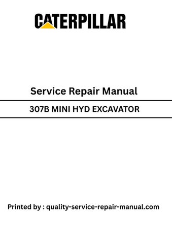
Note: The hydraulic accumulator is installed in the pilot manifold that is located behind the right rear access door.
At operating temperature the implement hydraulic oil tank is hot and under pressure. Hot oil can cause burns.
To prevent possible injury, release the pressure in the implement hydraulic system before hydraulic lines or components are disconnected or removed.
1. Release the pressure in the hydraulic system.
ReferenceRefer to Disassembly and Assembly, "Hydraulic System Pressure - Release".
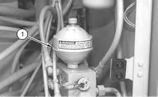
Illustration 1
g00530693
Note: Do not release the nitrogen from the hydraulic accumulator unless the unit will be disassembled.
2. Remove hydraulic accumulator (1) by turning the nut on the bottom. Remove the O-ring seal from the accumulator.
Installation Procedure
Note: Prior to installing the accumulator, check the condition of the O-ring seal. If the seal is damaged, use new parts for replacement.
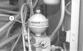
Illustration 2
g00530693
1. Install the O-ring seal in the accumulator. Install hydraulic accumulator (1) by tightening the nut on the bottom.
Note: Tighten the cap on the accumulator to a torque of 3.0 ± 0.3 N·m (27 ± 3 lb in).
2. Use Tool (A) to charge the hydraulic accumulator.
3. Check the oil level in the hydraulic oil tank. Refer to Operation and Maintenance Manual, "Hydraulic System Oil Level - Check".
4. Fill the hydraulic oil tank to the correct level. Refer to Operation and Maintenance Manual, "Hydraulic System Oil - Change" and Operation and Maintenance Manual, "Refill Capacities".
Product: MINI HYD EXCAVATOR
Model: 307B MINI HYD EXCAVATOR 7DZ
Configuration: 307B TRACK-TYPE EXCAVATOR /SWING BOOM ARRANGEME/ 7DZ00001-UP (MACHINE) POWERED BY 4M40 ENGINE
Disassembly and Assembly 307B Excavator Machine Systems
Media Number -RENR1091-02 Publication Date -01/09/2000 Date Updated -28/11/2001
i01787938
Auxiliary Hydraulic Pump - Assemble - Blade
SMCS - 5073-AX
Assembly Procedure
Table 1 Required Tools
A 1P-0510 Driver Group 1
Failure to properly assemble parts or failure to follow established procedures can lead to damage of the parts and assembly.
To avoid damage to parts, always identify and mark the parts so that they can be installed in the same location. Ensure that gear surfaces align. Never force parts during assembly.
1. Thoroughly clean all parts of the auxiliary pump prior to assembly. Put clean hydraulic oil on the parts during assembly. Check the condition of all parts of the pump assembly. If any of the parts are worn or damaged, use new parts for replacement.
This is the sample of the manual
Click on the download link for complete Manual
Illustration 1
2. Ensure that dowels (15) are installed in the center case.
3. Use Tooling (A) to install bushings (16) in thrust plate (17). Install each bushing even with the outside of the thrust plate. Install thrust plate (17), plate (18) and square ring (19) in the correct positions in the center case.
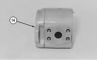
Illustration 2
4. Install end frame (14) on the center case.
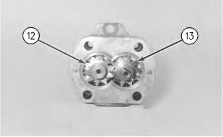
Illustration 3
5. Install idler gear (12) and drive gear (13) in the center case.

Illustration 4
g00535976
6. Use Tooling (A) to install the bushings in thrust plate (11). Install each bushing even with the outside of the thrust plate. Install thrust plate (11) in the center case.
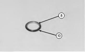
Illustration 5
7. Install O-ring seals (10) on guides (8).
g00535997
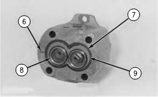
Illustration 6
g00535999
8. Install plate (9) and square ring (7) in the center case. Install guides (8).
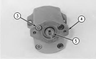
Illustration 7
g00536002
9. Position end plate (4) on the center case. Install bolts (3). Tighten the bolts to a torque of 62 ± 7 N·m (45 ± 5 lb ft).
10. Install coupling (5) on the drive gear of the pump.
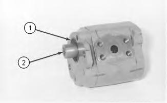
Illustration 8
11. Install O-ring seal (1) in the end frame.
12. Install coupling (2) on the drive gear.
End By: Install the auxiliary hydraulic pump. Refer to Disassembly and Assembly, "Auxiliary Hydraulic Pump - Install".
Copyright 1993 - 2020 Caterpillar Inc. All Rights Reserved. Private Network For SIS Licensees.
Product: MINI HYD EXCAVATOR
Model: 307B MINI HYD EXCAVATOR 7DZ
Configuration: 307B TRACK-TYPE EXCAVATOR /SWING BOOM ARRANGEME/ 7DZ00001-UP (MACHINE) POWERED BY 4M40 ENGINE
Disassembly and Assembly 307B Excavator Machine Systems
Media Number -RENR1091-02 Publication Date -01/09/2000 Date Updated -28/11/2001
Auxiliary Hydraulic Pump - Disassemble - Blade
SMCS - 5073-AX
Disassembly Procedure
Start By:
i01787934
A. Remove auxiliary hydraulic pump assembly. Refer to Disassembly and Assembly, "Auxiliary Hydraulic Pump - Remove".
NOTICE
Failure to properly assemble parts or failure to follow established procedures can lead to damage of the parts and assembly.
To avoid damage to parts, always identify and mark the parts so that they can be installed in the same location. Ensure that gear surfaces align. Never force parts during assembly.
1. Thoroughly clean the outside of the auxiliary hydraulic pump.
Illustration 1
2. Remove coupling (2) from the drive gear. Remove O-ring seal (1) from the end frame.
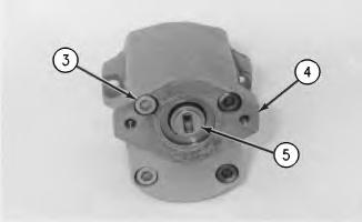
Illustration 2
g00536002
3. Remove coupling (5) from the drive gear of the pump.
4. Remove bolts (3) and separate end plate (4) from the center case.
Illustration 3
5. Remove guides (8) from the center case.
g00535999
Note: Note the position of plate (9) in the center case. The plate must be reinstalled in the plate's original position.
6. Remove square ring (7) and plate (9) from the center case.
7. If necessary, remove dowels (6) from the center case.
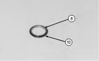
Illustration 4
g00535997
8. Remove O-ring seal (10) from each guide (8).
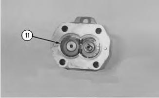
Illustration 5
g00535976
9. Remove thrust plate (11) from the center case. Remove the bushings from thrust plate (11).
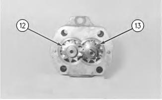
Illustration 6
g00535974
10. Remove idler gear (12) and drive gear (13).
Illustration 7
g00535972
11. Remove end frame (14) from the center case.

Illustration 8 g00535971
Note: Note the position of plate (18) and thrust plate (17) from the center case. The plate and the thrust plate must be installed in the original positions in the center case.
12. Remove square ring (19), plate (18) and thrust plate (17) from the center case. Remove bushings (16) from thrust plate (17).
13. If necessary, remove dowels (15) from the center case.
Product: MINI HYD EXCAVATOR
Model: 307B MINI HYD EXCAVATOR 7DZ
Configuration: 307B TRACK-TYPE EXCAVATOR /SWING BOOM ARRANGEME/ 7DZ00001-UP (MACHINE) POWERED BY 4M40 ENGINE
Disassembly and Assembly 307B Excavator Machine Systems
Media Number -RENR1091-02
Publication Date -01/09/2000
Auxiliary Hydraulic Pump - Install
SMCS - 5073-AX
Pump Assembly (Blade or Swing Boom)
NOTICE
Date Updated -28/11/2001
i01027486
Care must be taken to ensure that fluids are contained during performance of inspection, maintenance, testing, adjusting and repair of the product. Be prepared to collect the fluid with suitable containers before opening any compartment or disassembling any component containing fluids.
Refer to Special Publication, NENG2500, "Caterpillar Tools and Shop Products Guide" for tools and supplies suitable to collect and contain fluids on Caterpillar products.
Dispose of all fluids according to local regulations and mandates.
1. Check the condition of the O-ring seals that are used in the ends of the hose assemblies that connect to the pump assembly. Check the condition of the O-ring seal that is used in the frame of the auxiliary hydraulic pump assembly. If the seals are damaged, use new parts for replacement.
1
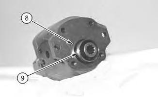
2. Install O-ring seal (8) in the frame of the pump assembly. Install bushing (9) in the frame of the pump assembly.
2
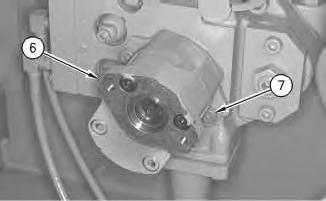
3. Put clean hydraulic oil on O-ring seal (8). Put the auxiliary hydraulic pump assembly (6) in position on the main hydraulic pump. Install two socket head bolts (7) that hold the pump assembly in place. Tighten the socket head bolts to a torque of 62 ± 7 N·m (45 ± 5 lb ft).
3
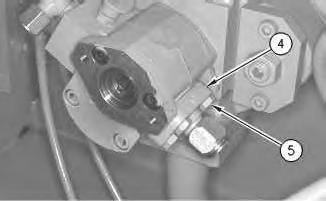
4. Put the O-ring seal and connecting block (4) in position on the pump assembly. Install four bolts (5). Tighten the four bolts to a torque of 80 ± 7 N·m (60 ± 5 lb ft).
4
5. Put the O-ring seal and the connecting block (3) in position on the pump assembly. Install the four socket head bolts (2). Tighten the four socket head bolts to a torque of 80 ± 7 N·m (60 ± 5 lb ft).
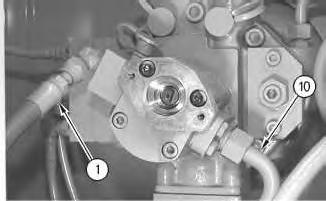
6. Connect hose assemblies (1) and (10) to the auxiliary hydraulic pump assembly. Tighten hose assembly (1) to a torque of 80 ± 7 N·m (59 ± 5 lb ft). Tighten hose assembly (10) to a torque of 110 ± 10 N·m (81 ± 7 lb ft).
End By: Install the pilot pump. Refer to Disassembly and Assembly, "Gear Pump (Pilot) - Install" in this manual.
Copyright 1993 - 2020 Caterpillar Inc. All Rights Reserved. Private Network For SIS Licensees.
Product: MINI HYD EXCAVATOR
Model: 307B MINI HYD EXCAVATOR 7DZ
Configuration: 307B TRACK-TYPE EXCAVATOR /SWING BOOM ARRANGEME/ 7DZ00001-UP (MACHINE) POWERED BY 4M40 ENGINE
Disassembly and Assembly 307B Excavator Machine Systems
Media Number -RENR1091-02
Publication Date -01/09/2000
Auxiliary Hydraulic Pump - Remove
SMCS - 5073-AX
Removal Procedure
Start By:
Date Updated -28/11/2001
i01027485
A. Remove the pilot pump. Refer to Disassembly and Assembly, "Gear Pump (Pilot) - Remove and Install" in this manual.
NOTICE
Care must be taken to ensure that fluids are contained during performance of inspection, maintenance, testing, adjusting and repair of the product. Be prepared to collect the fluid with suitable containers before opening any compartment or disassembling any component containing fluids.
Refer to Special Publication, NENG2500, "Caterpillar Tools and Shop Products Guide" for tools and supplies suitable to collect and contain fluids on Caterpillar products.
Dispose of all fluids according to local regulations and mandates.
1
1. Disconnect two hose assemblies (1) and (10) from the auxiliary pump assembly.
Note: Put plugs in the ends of the hoses in order to keep dirt and debris out of the hydraulic system. Put identification marks on all of the hoses and lines for assembly purposes.
2
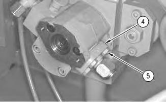
Illustration 3 g00536202
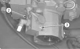
2. Remove four socket head bolts (2), the connecting block (3) and the O-ring seal from the pump assembly.
3. Remove four bolts (5), the connecting block (4) and the O-ring seal from the pump assembly.
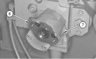
Illustration 4
g00536203
4. Remove two socket head bolts (7) and auxiliary pump assembly (6) from the main hydraulic oil pump.
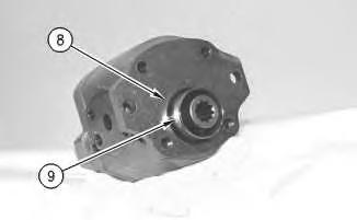
Illustration 5
g00536204
5. Remove O-ring seal (8) and bushing (9) from the pump assembly. Bushing (9) is a slip fit.
This is the sample of the manual
Click on the download link for complete Manual
Product: MINI HYD EXCAVATOR
Model: 307B MINI HYD EXCAVATOR 7DZ
Configuration: 307B TRACK-TYPE EXCAVATOR /SWING BOOM ARRANGEME/ 7DZ00001-UP (MACHINE) POWERED BY 4M40 ENGINE
Disassembly and Assembly 307B Excavator Machine Systems
Media Number -RENR1091-02
Publication Date -01/09/2000
Blade - Remove and Install
SMCS - 6060-010
Removal Procedure
Start By:
Date Updated -28/11/2001
A. Remove the blade cylinder. Refer to Disassembly and Assembly, "Blade Cylinder - Remove".
1. Put wood blocks under the arms of the blade in order to support the blade.
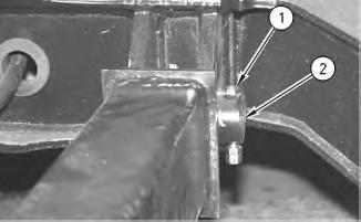
Illustration 1
2. Remove the nuts and retaining bolt (1), and remove pin assembly (2). Repeat this procedure for the remaining blade arm.